EP3627005A1 - Control apparatus for linear solenoid - Google Patents
Control apparatus for linear solenoid Download PDFInfo
- Publication number
- EP3627005A1 EP3627005A1 EP19185417.3A EP19185417A EP3627005A1 EP 3627005 A1 EP3627005 A1 EP 3627005A1 EP 19185417 A EP19185417 A EP 19185417A EP 3627005 A1 EP3627005 A1 EP 3627005A1
- Authority
- EP
- European Patent Office
- Prior art keywords
- equation
- driving current
- linear solenoid
- sslt
- control unit
- Prior art date
- Legal status (The legal status is an assumption and is not a legal conclusion. Google has not performed a legal analysis and makes no representation as to the accuracy of the status listed.)
- Granted
Links
- 238000000034 method Methods 0.000 claims abstract description 73
- 238000012546 transfer Methods 0.000 claims abstract description 66
- 238000013461 design Methods 0.000 claims abstract description 48
- 230000005540 biological transmission Effects 0.000 claims description 37
- 230000007246 mechanism Effects 0.000 claims description 16
- 239000012530 fluid Substances 0.000 description 94
- 230000006870 function Effects 0.000 description 82
- 239000011159 matrix material Substances 0.000 description 66
- 238000004088 simulation Methods 0.000 description 46
- 238000010586 diagram Methods 0.000 description 36
- 230000008859 change Effects 0.000 description 34
- 230000004043 responsiveness Effects 0.000 description 33
- 230000004044 response Effects 0.000 description 32
- 230000001276 controlling effect Effects 0.000 description 26
- 230000008569 process Effects 0.000 description 26
- 238000010276 construction Methods 0.000 description 17
- 230000000052 comparative effect Effects 0.000 description 16
- 238000004364 calculation method Methods 0.000 description 13
- 238000004891 communication Methods 0.000 description 12
- 238000012937 correction Methods 0.000 description 10
- 238000001514 detection method Methods 0.000 description 10
- 238000009795 derivation Methods 0.000 description 9
- 238000012938 design process Methods 0.000 description 8
- 238000004519 manufacturing process Methods 0.000 description 8
- 230000033001 locomotion Effects 0.000 description 7
- 239000000203 mixture Substances 0.000 description 7
- 230000009471 action Effects 0.000 description 6
- 238000009472 formulation Methods 0.000 description 6
- 230000032683 aging Effects 0.000 description 5
- 230000004048 modification Effects 0.000 description 5
- 238000012986 modification Methods 0.000 description 5
- 238000003825 pressing Methods 0.000 description 5
- 230000001105 regulatory effect Effects 0.000 description 5
- 230000002441 reversible effect Effects 0.000 description 5
- 230000003068 static effect Effects 0.000 description 5
- 230000003578 releasing effect Effects 0.000 description 4
- 230000003111 delayed effect Effects 0.000 description 3
- 230000001419 dependent effect Effects 0.000 description 3
- 238000011156 evaluation Methods 0.000 description 3
- 230000002401 inhibitory effect Effects 0.000 description 3
- 230000007935 neutral effect Effects 0.000 description 3
- 230000009467 reduction Effects 0.000 description 3
- 238000004378 air conditioning Methods 0.000 description 2
- 238000013473 artificial intelligence Methods 0.000 description 2
- 238000011960 computer-aided design Methods 0.000 description 2
- 238000013500 data storage Methods 0.000 description 2
- 230000007423 decrease Effects 0.000 description 2
- 238000007689 inspection Methods 0.000 description 2
- 230000002829 reductive effect Effects 0.000 description 2
- 230000001131 transforming effect Effects 0.000 description 2
- XEEYBQQBJWHFJM-UHFFFAOYSA-N Iron Chemical group [Fe] XEEYBQQBJWHFJM-UHFFFAOYSA-N 0.000 description 1
- 238000006243 chemical reaction Methods 0.000 description 1
- 238000007906 compression Methods 0.000 description 1
- 230000006835 compression Effects 0.000 description 1
- 230000006866 deterioration Effects 0.000 description 1
- 238000007599 discharging Methods 0.000 description 1
- 238000004880 explosion Methods 0.000 description 1
- 230000006872 improvement Effects 0.000 description 1
- 230000036961 partial effect Effects 0.000 description 1
- 238000007789 sealing Methods 0.000 description 1
- 230000009466 transformation Effects 0.000 description 1
Images


Classifications
-
- G—PHYSICS
- G05—CONTROLLING; REGULATING
- G05D—SYSTEMS FOR CONTROLLING OR REGULATING NON-ELECTRIC VARIABLES
- G05D16/00—Control of fluid pressure
- G05D16/20—Control of fluid pressure characterised by the use of electric means
- G05D16/2006—Control of fluid pressure characterised by the use of electric means with direct action of electric energy on controlling means
- G05D16/2013—Control of fluid pressure characterised by the use of electric means with direct action of electric energy on controlling means using throttling means as controlling means
- G05D16/2022—Control of fluid pressure characterised by the use of electric means with direct action of electric energy on controlling means using throttling means as controlling means actuated by a proportional solenoid
-
- F—MECHANICAL ENGINEERING; LIGHTING; HEATING; WEAPONS; BLASTING
- F16—ENGINEERING ELEMENTS AND UNITS; GENERAL MEASURES FOR PRODUCING AND MAINTAINING EFFECTIVE FUNCTIONING OF MACHINES OR INSTALLATIONS; THERMAL INSULATION IN GENERAL
- F16H—GEARING
- F16H61/00—Control functions within control units of change-speed- or reversing-gearings for conveying rotary motion ; Control of exclusively fluid gearing, friction gearing, gearings with endless flexible members or other particular types of gearing
- F16H61/0003—Arrangement or mounting of elements of the control apparatus, e.g. valve assemblies or snapfittings of valves; Arrangements of the control unit on or in the transmission gearbox
- F16H61/0009—Hydraulic control units for transmission control, e.g. assembly of valve plates or valve units
-
- F—MECHANICAL ENGINEERING; LIGHTING; HEATING; WEAPONS; BLASTING
- F01—MACHINES OR ENGINES IN GENERAL; ENGINE PLANTS IN GENERAL; STEAM ENGINES
- F01L—CYCLICALLY OPERATING VALVES FOR MACHINES OR ENGINES
- F01L9/00—Valve-gear or valve arrangements actuated non-mechanically
- F01L9/10—Valve-gear or valve arrangements actuated non-mechanically by fluid means, e.g. hydraulic
-
- F—MECHANICAL ENGINEERING; LIGHTING; HEATING; WEAPONS; BLASTING
- F01—MACHINES OR ENGINES IN GENERAL; ENGINE PLANTS IN GENERAL; STEAM ENGINES
- F01L—CYCLICALLY OPERATING VALVES FOR MACHINES OR ENGINES
- F01L9/00—Valve-gear or valve arrangements actuated non-mechanically
- F01L9/20—Valve-gear or valve arrangements actuated non-mechanically by electric means
- F01L9/26—Driving circuits therefor
-
- F—MECHANICAL ENGINEERING; LIGHTING; HEATING; WEAPONS; BLASTING
- F02—COMBUSTION ENGINES; HOT-GAS OR COMBUSTION-PRODUCT ENGINE PLANTS
- F02D—CONTROLLING COMBUSTION ENGINES
- F02D41/00—Electrical control of supply of combustible mixture or its constituents
- F02D41/0002—Controlling intake air
-
- F—MECHANICAL ENGINEERING; LIGHTING; HEATING; WEAPONS; BLASTING
- F02—COMBUSTION ENGINES; HOT-GAS OR COMBUSTION-PRODUCT ENGINE PLANTS
- F02D—CONTROLLING COMBUSTION ENGINES
- F02D41/00—Electrical control of supply of combustible mixture or its constituents
- F02D41/02—Circuit arrangements for generating control signals
- F02D41/14—Introducing closed-loop corrections
-
- F—MECHANICAL ENGINEERING; LIGHTING; HEATING; WEAPONS; BLASTING
- F02—COMBUSTION ENGINES; HOT-GAS OR COMBUSTION-PRODUCT ENGINE PLANTS
- F02D—CONTROLLING COMBUSTION ENGINES
- F02D45/00—Electrical control not provided for in groups F02D41/00 - F02D43/00
-
- F—MECHANICAL ENGINEERING; LIGHTING; HEATING; WEAPONS; BLASTING
- F16—ENGINEERING ELEMENTS AND UNITS; GENERAL MEASURES FOR PRODUCING AND MAINTAINING EFFECTIVE FUNCTIONING OF MACHINES OR INSTALLATIONS; THERMAL INSULATION IN GENERAL
- F16H—GEARING
- F16H61/00—Control functions within control units of change-speed- or reversing-gearings for conveying rotary motion ; Control of exclusively fluid gearing, friction gearing, gearings with endless flexible members or other particular types of gearing
- F16H61/02—Control functions within control units of change-speed- or reversing-gearings for conveying rotary motion ; Control of exclusively fluid gearing, friction gearing, gearings with endless flexible members or other particular types of gearing characterised by the signals used
- F16H61/0202—Control functions within control units of change-speed- or reversing-gearings for conveying rotary motion ; Control of exclusively fluid gearing, friction gearing, gearings with endless flexible members or other particular types of gearing characterised by the signals used the signals being electric
- F16H61/0251—Elements specially adapted for electric control units, e.g. valves for converting electrical signals to fluid signals
-
- F—MECHANICAL ENGINEERING; LIGHTING; HEATING; WEAPONS; BLASTING
- F16—ENGINEERING ELEMENTS AND UNITS; GENERAL MEASURES FOR PRODUCING AND MAINTAINING EFFECTIVE FUNCTIONING OF MACHINES OR INSTALLATIONS; THERMAL INSULATION IN GENERAL
- F16H—GEARING
- F16H61/00—Control functions within control units of change-speed- or reversing-gearings for conveying rotary motion ; Control of exclusively fluid gearing, friction gearing, gearings with endless flexible members or other particular types of gearing
- F16H61/02—Control functions within control units of change-speed- or reversing-gearings for conveying rotary motion ; Control of exclusively fluid gearing, friction gearing, gearings with endless flexible members or other particular types of gearing characterised by the signals used
- F16H61/0262—Control functions within control units of change-speed- or reversing-gearings for conveying rotary motion ; Control of exclusively fluid gearing, friction gearing, gearings with endless flexible members or other particular types of gearing characterised by the signals used the signals being hydraulic
- F16H61/0265—Control functions within control units of change-speed- or reversing-gearings for conveying rotary motion ; Control of exclusively fluid gearing, friction gearing, gearings with endless flexible members or other particular types of gearing characterised by the signals used the signals being hydraulic for gearshift control, e.g. control functions for performing shifting or generation of shift signals
- F16H61/0267—Layout of hydraulic control circuits, e.g. arrangement of valves
-
- F—MECHANICAL ENGINEERING; LIGHTING; HEATING; WEAPONS; BLASTING
- F16—ENGINEERING ELEMENTS AND UNITS; GENERAL MEASURES FOR PRODUCING AND MAINTAINING EFFECTIVE FUNCTIONING OF MACHINES OR INSTALLATIONS; THERMAL INSULATION IN GENERAL
- F16H—GEARING
- F16H61/00—Control functions within control units of change-speed- or reversing-gearings for conveying rotary motion ; Control of exclusively fluid gearing, friction gearing, gearings with endless flexible members or other particular types of gearing
- F16H61/02—Control functions within control units of change-speed- or reversing-gearings for conveying rotary motion ; Control of exclusively fluid gearing, friction gearing, gearings with endless flexible members or other particular types of gearing characterised by the signals used
- F16H61/0262—Control functions within control units of change-speed- or reversing-gearings for conveying rotary motion ; Control of exclusively fluid gearing, friction gearing, gearings with endless flexible members or other particular types of gearing characterised by the signals used the signals being hydraulic
- F16H61/0276—Elements specially adapted for hydraulic control units, e.g. valves
-
- F—MECHANICAL ENGINEERING; LIGHTING; HEATING; WEAPONS; BLASTING
- F16—ENGINEERING ELEMENTS AND UNITS; GENERAL MEASURES FOR PRODUCING AND MAINTAINING EFFECTIVE FUNCTIONING OF MACHINES OR INSTALLATIONS; THERMAL INSULATION IN GENERAL
- F16H—GEARING
- F16H61/00—Control functions within control units of change-speed- or reversing-gearings for conveying rotary motion ; Control of exclusively fluid gearing, friction gearing, gearings with endless flexible members or other particular types of gearing
- F16H61/38—Control of exclusively fluid gearing
- F16H61/40—Control of exclusively fluid gearing hydrostatic
- F16H61/4069—Valves related to the control of neutral, e.g. shut off valves
-
- F—MECHANICAL ENGINEERING; LIGHTING; HEATING; WEAPONS; BLASTING
- F16—ENGINEERING ELEMENTS AND UNITS; GENERAL MEASURES FOR PRODUCING AND MAINTAINING EFFECTIVE FUNCTIONING OF MACHINES OR INSTALLATIONS; THERMAL INSULATION IN GENERAL
- F16K—VALVES; TAPS; COCKS; ACTUATING-FLOATS; DEVICES FOR VENTING OR AERATING
- F16K31/00—Actuating devices; Operating means; Releasing devices
- F16K31/02—Actuating devices; Operating means; Releasing devices electric; magnetic
- F16K31/06—Actuating devices; Operating means; Releasing devices electric; magnetic using a magnet, e.g. diaphragm valves, cutting off by means of a liquid
- F16K31/0675—Electromagnet aspects, e.g. electric supply therefor
-
- F—MECHANICAL ENGINEERING; LIGHTING; HEATING; WEAPONS; BLASTING
- F16—ENGINEERING ELEMENTS AND UNITS; GENERAL MEASURES FOR PRODUCING AND MAINTAINING EFFECTIVE FUNCTIONING OF MACHINES OR INSTALLATIONS; THERMAL INSULATION IN GENERAL
- F16K—VALVES; TAPS; COCKS; ACTUATING-FLOATS; DEVICES FOR VENTING OR AERATING
- F16K31/00—Actuating devices; Operating means; Releasing devices
- F16K31/12—Actuating devices; Operating means; Releasing devices actuated by fluid
- F16K31/36—Actuating devices; Operating means; Releasing devices actuated by fluid in which fluid from the circuit is constantly supplied to the fluid motor
-
- G—PHYSICS
- G05—CONTROLLING; REGULATING
- G05B—CONTROL OR REGULATING SYSTEMS IN GENERAL; FUNCTIONAL ELEMENTS OF SUCH SYSTEMS; MONITORING OR TESTING ARRANGEMENTS FOR SUCH SYSTEMS OR ELEMENTS
- G05B13/00—Adaptive control systems, i.e. systems automatically adjusting themselves to have a performance which is optimum according to some preassigned criterion
- G05B13/02—Adaptive control systems, i.e. systems automatically adjusting themselves to have a performance which is optimum according to some preassigned criterion electric
- G05B13/04—Adaptive control systems, i.e. systems automatically adjusting themselves to have a performance which is optimum according to some preassigned criterion electric involving the use of models or simulators
-
- H—ELECTRICITY
- H01—ELECTRIC ELEMENTS
- H01F—MAGNETS; INDUCTANCES; TRANSFORMERS; SELECTION OF MATERIALS FOR THEIR MAGNETIC PROPERTIES
- H01F7/00—Magnets
- H01F7/06—Electromagnets; Actuators including electromagnets
- H01F7/064—Circuit arrangements for actuating electromagnets
-
- H—ELECTRICITY
- H01—ELECTRIC ELEMENTS
- H01F—MAGNETS; INDUCTANCES; TRANSFORMERS; SELECTION OF MATERIALS FOR THEIR MAGNETIC PROPERTIES
- H01F7/00—Magnets
- H01F7/06—Electromagnets; Actuators including electromagnets
- H01F7/08—Electromagnets; Actuators including electromagnets with armatures
- H01F7/18—Circuit arrangements for obtaining desired operating characteristics, e.g. for slow operation, for sequential energisation of windings, for high-speed energisation of windings
- H01F7/1844—Monitoring or fail-safe circuits
-
- F—MECHANICAL ENGINEERING; LIGHTING; HEATING; WEAPONS; BLASTING
- F02—COMBUSTION ENGINES; HOT-GAS OR COMBUSTION-PRODUCT ENGINE PLANTS
- F02D—CONTROLLING COMBUSTION ENGINES
- F02D41/00—Electrical control of supply of combustible mixture or its constituents
- F02D41/0002—Controlling intake air
- F02D2041/001—Controlling intake air for engines with variable valve actuation
-
- F—MECHANICAL ENGINEERING; LIGHTING; HEATING; WEAPONS; BLASTING
- F16—ENGINEERING ELEMENTS AND UNITS; GENERAL MEASURES FOR PRODUCING AND MAINTAINING EFFECTIVE FUNCTIONING OF MACHINES OR INSTALLATIONS; THERMAL INSULATION IN GENERAL
- F16H—GEARING
- F16H61/00—Control functions within control units of change-speed- or reversing-gearings for conveying rotary motion ; Control of exclusively fluid gearing, friction gearing, gearings with endless flexible members or other particular types of gearing
- F16H2061/0075—Control functions within control units of change-speed- or reversing-gearings for conveying rotary motion ; Control of exclusively fluid gearing, friction gearing, gearings with endless flexible members or other particular types of gearing characterised by a particular control method
- F16H2061/0078—Linear control, e.g. PID, state feedback or Kalman
-
- F—MECHANICAL ENGINEERING; LIGHTING; HEATING; WEAPONS; BLASTING
- F16—ENGINEERING ELEMENTS AND UNITS; GENERAL MEASURES FOR PRODUCING AND MAINTAINING EFFECTIVE FUNCTIONING OF MACHINES OR INSTALLATIONS; THERMAL INSULATION IN GENERAL
- F16H—GEARING
- F16H61/00—Control functions within control units of change-speed- or reversing-gearings for conveying rotary motion ; Control of exclusively fluid gearing, friction gearing, gearings with endless flexible members or other particular types of gearing
- F16H61/02—Control functions within control units of change-speed- or reversing-gearings for conveying rotary motion ; Control of exclusively fluid gearing, friction gearing, gearings with endless flexible members or other particular types of gearing characterised by the signals used
- F16H61/0202—Control functions within control units of change-speed- or reversing-gearings for conveying rotary motion ; Control of exclusively fluid gearing, friction gearing, gearings with endless flexible members or other particular types of gearing characterised by the signals used the signals being electric
- F16H61/0251—Elements specially adapted for electric control units, e.g. valves for converting electrical signals to fluid signals
- F16H2061/0255—Solenoid valve using PWM or duty-cycle control
-
- F—MECHANICAL ENGINEERING; LIGHTING; HEATING; WEAPONS; BLASTING
- F16—ENGINEERING ELEMENTS AND UNITS; GENERAL MEASURES FOR PRODUCING AND MAINTAINING EFFECTIVE FUNCTIONING OF MACHINES OR INSTALLATIONS; THERMAL INSULATION IN GENERAL
- F16H—GEARING
- F16H61/00—Control functions within control units of change-speed- or reversing-gearings for conveying rotary motion ; Control of exclusively fluid gearing, friction gearing, gearings with endless flexible members or other particular types of gearing
- F16H61/02—Control functions within control units of change-speed- or reversing-gearings for conveying rotary motion ; Control of exclusively fluid gearing, friction gearing, gearings with endless flexible members or other particular types of gearing characterised by the signals used
- F16H61/0202—Control functions within control units of change-speed- or reversing-gearings for conveying rotary motion ; Control of exclusively fluid gearing, friction gearing, gearings with endless flexible members or other particular types of gearing characterised by the signals used the signals being electric
- F16H61/0251—Elements specially adapted for electric control units, e.g. valves for converting electrical signals to fluid signals
- F16H2061/0258—Proportional solenoid valve
-
- F—MECHANICAL ENGINEERING; LIGHTING; HEATING; WEAPONS; BLASTING
- F16—ENGINEERING ELEMENTS AND UNITS; GENERAL MEASURES FOR PRODUCING AND MAINTAINING EFFECTIVE FUNCTIONING OF MACHINES OR INSTALLATIONS; THERMAL INSULATION IN GENERAL
- F16H—GEARING
- F16H61/00—Control functions within control units of change-speed- or reversing-gearings for conveying rotary motion ; Control of exclusively fluid gearing, friction gearing, gearings with endless flexible members or other particular types of gearing
- F16H61/02—Control functions within control units of change-speed- or reversing-gearings for conveying rotary motion ; Control of exclusively fluid gearing, friction gearing, gearings with endless flexible members or other particular types of gearing characterised by the signals used
- F16H61/0262—Control functions within control units of change-speed- or reversing-gearings for conveying rotary motion ; Control of exclusively fluid gearing, friction gearing, gearings with endless flexible members or other particular types of gearing characterised by the signals used the signals being hydraulic
- F16H61/0276—Elements specially adapted for hydraulic control units, e.g. valves
- F16H2061/0279—Details of hydraulic valves, e.g. lands, ports, spools or springs
-
- F—MECHANICAL ENGINEERING; LIGHTING; HEATING; WEAPONS; BLASTING
- F16—ENGINEERING ELEMENTS AND UNITS; GENERAL MEASURES FOR PRODUCING AND MAINTAINING EFFECTIVE FUNCTIONING OF MACHINES OR INSTALLATIONS; THERMAL INSULATION IN GENERAL
- F16H—GEARING
- F16H2200/00—Transmissions for multiple ratios
- F16H2200/20—Transmissions using gears with orbital motion
- F16H2200/203—Transmissions using gears with orbital motion characterised by the engaging friction means not of the freewheel type, e.g. friction clutches or brakes
- F16H2200/2046—Transmissions using gears with orbital motion characterised by the engaging friction means not of the freewheel type, e.g. friction clutches or brakes with six engaging means
-
- F—MECHANICAL ENGINEERING; LIGHTING; HEATING; WEAPONS; BLASTING
- F16—ENGINEERING ELEMENTS AND UNITS; GENERAL MEASURES FOR PRODUCING AND MAINTAINING EFFECTIVE FUNCTIONING OF MACHINES OR INSTALLATIONS; THERMAL INSULATION IN GENERAL
- F16H—GEARING
- F16H2200/00—Transmissions for multiple ratios
- F16H2200/20—Transmissions using gears with orbital motion
- F16H2200/203—Transmissions using gears with orbital motion characterised by the engaging friction means not of the freewheel type, e.g. friction clutches or brakes
- F16H2200/2069—Transmissions using gears with orbital motion characterised by the engaging friction means not of the freewheel type, e.g. friction clutches or brakes using two freewheel mechanism
-
- F—MECHANICAL ENGINEERING; LIGHTING; HEATING; WEAPONS; BLASTING
- F16—ENGINEERING ELEMENTS AND UNITS; GENERAL MEASURES FOR PRODUCING AND MAINTAINING EFFECTIVE FUNCTIONING OF MACHINES OR INSTALLATIONS; THERMAL INSULATION IN GENERAL
- F16H—GEARING
- F16H59/00—Control inputs to control units of change-speed-, or reversing-gearings for conveying rotary motion
- F16H59/14—Inputs being a function of torque or torque demand
- F16H59/24—Inputs being a function of torque or torque demand dependent on the throttle opening
-
- F—MECHANICAL ENGINEERING; LIGHTING; HEATING; WEAPONS; BLASTING
- F16—ENGINEERING ELEMENTS AND UNITS; GENERAL MEASURES FOR PRODUCING AND MAINTAINING EFFECTIVE FUNCTIONING OF MACHINES OR INSTALLATIONS; THERMAL INSULATION IN GENERAL
- F16H—GEARING
- F16H59/00—Control inputs to control units of change-speed-, or reversing-gearings for conveying rotary motion
- F16H59/36—Inputs being a function of speed
-
- F—MECHANICAL ENGINEERING; LIGHTING; HEATING; WEAPONS; BLASTING
- F16—ENGINEERING ELEMENTS AND UNITS; GENERAL MEASURES FOR PRODUCING AND MAINTAINING EFFECTIVE FUNCTIONING OF MACHINES OR INSTALLATIONS; THERMAL INSULATION IN GENERAL
- F16H—GEARING
- F16H59/00—Control inputs to control units of change-speed-, or reversing-gearings for conveying rotary motion
- F16H59/68—Inputs being a function of gearing status
-
- H—ELECTRICITY
- H01—ELECTRIC ELEMENTS
- H01F—MAGNETS; INDUCTANCES; TRANSFORMERS; SELECTION OF MATERIALS FOR THEIR MAGNETIC PROPERTIES
- H01F7/00—Magnets
- H01F7/06—Electromagnets; Actuators including electromagnets
- H01F7/08—Electromagnets; Actuators including electromagnets with armatures
- H01F7/18—Circuit arrangements for obtaining desired operating characteristics, e.g. for slow operation, for sequential energisation of windings, for high-speed energisation of windings
- H01F7/1844—Monitoring or fail-safe circuits
- H01F2007/1861—Monitoring or fail-safe circuits using derivative of measured variable
-
- H—ELECTRICITY
- H01—ELECTRIC ELEMENTS
- H01F—MAGNETS; INDUCTANCES; TRANSFORMERS; SELECTION OF MATERIALS FOR THEIR MAGNETIC PROPERTIES
- H01F7/00—Magnets
- H01F7/06—Electromagnets; Actuators including electromagnets
- H01F7/08—Electromagnets; Actuators including electromagnets with armatures
- H01F7/18—Circuit arrangements for obtaining desired operating characteristics, e.g. for slow operation, for sequential energisation of windings, for high-speed energisation of windings
- H01F7/1844—Monitoring or fail-safe circuits
- H01F2007/1866—Monitoring or fail-safe circuits with regulation loop
-
- H—ELECTRICITY
- H01—ELECTRIC ELEMENTS
- H01F—MAGNETS; INDUCTANCES; TRANSFORMERS; SELECTION OF MATERIALS FOR THEIR MAGNETIC PROPERTIES
- H01F7/00—Magnets
- H01F7/06—Electromagnets; Actuators including electromagnets
- H01F7/08—Electromagnets; Actuators including electromagnets with armatures
- H01F7/18—Circuit arrangements for obtaining desired operating characteristics, e.g. for slow operation, for sequential energisation of windings, for high-speed energisation of windings
- H01F2007/1888—Circuit arrangements for obtaining desired operating characteristics, e.g. for slow operation, for sequential energisation of windings, for high-speed energisation of windings using pulse width modulation
Definitions
- the present invention relates to a control apparatus for a linear solenoid, and is more particularly concerned with techniques for reducing adapting steps of adapting parameters of a feedback control system for controlling the linear solenoid.
- ECU electronice control unit
- parameters of a feedback control system for a linear solenoid which is used in a linear solenoid valve or the like, for example, are determined for each of various levels of a state value such as a power supply voltage, which is a responsiveness factor, and the determined parameters are stored in a ROM included in the electronic control unit, so that a constant responsiveness is realized in any level of the state value such as the power supply voltage.
- a control apparatus for a linear solenoid is disclosed in Patent Document 1.
- the present invention was made in view of the background art described above. It is therefore an object of the present invention to provide a control apparatus for a linear solenoid, which is capable of reducing adapting steps for adapting the parameters that are applied in a feedback control system of the control apparatus. This object is achieved according to the following aspects of the present invention.
- a control apparatus for controlling a linear solenoid by controlling a driving current supplied to the linear solenoid, through a feedback control, wherein the feedback control is executed with a feedback control system having parameters that are determined in accordance with an ILQ design method, and wherein a gain of a transfer function, which represents a ratio of an output to a disturbance in the feedback control system, is lower than 0[dB] throughout all frequency ranges.
- the control apparatus may include: an electric circuit approximating portion configured to approximate an electric circuit of the linear solenoid, through which the driving current flows, by a series circuit of a resistance and an inductance; a first formulating portion configured to formulate a circuit equation related to an instantaneous value of the driving current flowing through the series circuit; a second formulating portion configured to formulate an equation related to a controlled variable for controlling the driving current; a recurrence-equation deriving portion configured to derive a recurrence equation from the equation related to the controlled variable; a recurrence-equation solving portion configured to solve the recurrence equation; a linearizing portion configured to linearize the solved recurrence equation is linearized by an approximation equation; and a transfer-function deriving
- the linear solenoid is provided in a linear solenoid valve, wherein the linear solenoid valve is configured to output a signal pressure whose magnitude corresponds to the driving current that is determined through the feedback control.
- the linear solenoid valve in a hydraulic control unit of an vehicle automatic transmission, is configured to supply the signal pressure to a line-pressure regulator valve for controlling a line pressure generated by the line-pressure regulator valve.
- the linear solenoid valve in a hydraulic control unit of an vehicle automatic transmission, is configured to supply the signal pressure to hydraulic friction engagement devices for controlling the hydraulic friction engagement devices that are operated to establish gear positions in the vehicle automatic transmission.
- the linear solenoid is provided in an actuator, wherein, in a hydraulic control unit for controlling a variable valve-timing mechanism configured to adjust opening/closing timing of valves of a vehicle engine, the actuator is configured to supply, to the variable valve-timing mechanism, a signal pressure whose magnitude corresponds to the driving current that is determined through the feedback control, for generating hydraulic pressure for adjusting the opening/closing timing.
- the driving current supplied to the linear solenoid is controlled by an input voltage that is obtained by causing a battery voltage to be subjected to an ON-OFF control based on a PWM signal, wherein an electric circuit of the linear solenoid, through which the driving current flows, is approximated by a series circuit of a resistance and an inductance, wherein a circuit equation related to an instantaneous value of the driving current flowing through the series circuit is formulated, wherein an equation related to a controlled variable for controlling the driving current is formulated, wherein the equation related to the controlled variable is derived as a recurrence equation, wherein the recurrence equation is solved, and the solved recurrence equation is linearized by an approximation equation, and wherein the transfer function of the feedback control is derived from the linearized equation related to the controlled variable, and the derived transfer function is used to determine the controlled variable.
- the circuit equation is formulated as equation (1)
- the equation related to the controlled variable that is an average value of the driving current in an n-th period (n: natural number)
- the recurrence equation is formulated as equation (3)
- the approximation equation is formulated as equation (4), where "t[s]” represents a time, " ⁇ [s]” represents each driving period of the PWM signal, “ ⁇ 1 [s]” represents an ON time that is a length of time for which the driving current (i(t)) is supplied to the linear solenoid in each driving period, "Pb[V]” represents the battery voltage, and "L(H)” represents the inductance.
- the driving current supplied to the linear solenoid is controlled by an input voltage that is obtained by causing a battery voltage to be subjected to an ON-OFF control based on a PWM signal, wherein a resistance Rz[ ⁇ ] of an electric circuit of the linear solenoid, through which the driving current flows, is calculated in accordance with equation (5), and an inductance L[H] of the electric circuit is calculated in accordance with equation (6), where " ⁇ [s]" represents each driving period of the PWM signal, “ ⁇ 1 [s]” represents an ON time that is a length of time for which the driving current is supplied to the linear solenoid in each driving period, “ ⁇ 2 [s]” represents an OFF time that is a length of time for which the driving current is not supplied to the linear solenoid in each driving period, "Pb[V]” represents the battery voltage, “Iavec[A]” represents an average value of the driving current in a converged state,
- the feedback control is executed with a feedback control system having parameters that are determined in accordance with the ILQ design method, wherein the gain of the transfer function, which represents the ratio of the output to the disturbance in the feedback control system, is lower than 0[dB] throughout all frequency ranges.
- the feedback control system having the parameters determined in accordance with the ILQ design method it is possible to reduce the adapting steps of adapting the parameters for each of various levels of the state value such as the power supply voltage, which is the responsiveness factor.
- the driving current is controlled such that the driving current is converged to a control target value (corresponding to a control command value) at a high responsiveness with respect to step change of the control target value and step change of a battery voltage of the drive circuit of the linear solenoid, without causing the control system to be vibrated and without causing coupled vibration in the linear solenoid.
- the linear solenoid is provided in the linear solenoid valve, wherein the linear solenoid valve is configured to output the signal pressure whose magnitude corresponds to the driving current that is determined through the feedback control.
- the driving current of the linear solenoid is converged to the control target value at a high responsiveness without the driving current being fluctuated, whereby the signal pressure outputted from the linear solenoid valve can be controlled to provide a high responsiveness without its fluctuation.
- the linear solenoid valve in the hydraulic control unit of the vehicle automatic transmission, is configured to supply the signal pressure to the line-pressure regulator valve for controlling the line pressure generated by the line-pressure regulator valve.
- the signal pressure which is for controlling the line pressure generated by the line-pressure regulator valve provided in the vehicle automatic transmission, can be controlled to provide a high responsiveness without its fluctuation, whereby the line pressure generated by the line-pressure regulator valve can be also controlled to provide a high responsiveness without its fluctuation.
- the linear solenoid valve is configured to supply the signal pressure to the hydraulic friction engagement devices for controlling the hydraulic friction engagement devices that are operated to establish the gear positions in the vehicle automatic transmission.
- the signal pressure which is for controlling the hydraulic friction engagement devices provided in the vehicle automatic transmission, can be controlled to provide a high responsiveness without its fluctuation, whereby engaging and releasing actions of each of the hydraulic friction engagement devices can be also controlled to provide a high responsiveness without its vibration.
- the linear solenoid is provided in the actuator, wherein, in the hydraulic control unit for controlling the variable valve-timing mechanism configured to adjust the opening/closing timing of the valves of the vehicle engine, the actuator is configured to supply, to the variable valve-timing mechanism, the signal pressure whose magnitude corresponds to the driving current that is determined through the feedback control, for generating the hydraulic pressure for adjusting the opening/closing timing.
- the signal pressure which is supplied to the variable valve-timing mechanism configured to adjust the opening/closing timing of the valves of the vehicle engine, can be controlled to provide a high responsiveness without its fluctuation, whereby the adjustment of the opening/closing timing by the variable valve-timing mechanism can be also controlled to provide a high responsiveness without its vibration.
- the driving current supplied to the linear solenoid is controlled by the input voltage that is obtained by causing the battery voltage to be subjected to an ON-OFF control based on the PWM signal, wherein the electric circuit of the linear solenoid, through which the driving current flows, is approximated by the series circuit of the resistance and the inductance, wherein the circuit equation related to the instantaneous value of the driving current flowing through the series circuit is formulated, wherein the equation related to the controlled variable for controlling the driving current is formulated, wherein the equation related to the controlled variable is derived as the recurrence equation, wherein the recurrence equation is solved, and the solved recurrence equation is linearized by the approximation equation, and wherein the transfer function of the feedback control is derived from the linearized equation related to the controlled variable, and the derived transfer function is used to determine the controlled variable.
- the transfer function which is accurately linearized and approximated, is derived whereby the controlled variable is determined by calculations, so that it is possible to reduce the adapting steps of adapting the parameters for each of various levels of the state value such as the power supply voltage, which is the responsiveness factor.
- the circuit equation is formulated as the equation (1), the equation related to the controlled variable that is the average value of the driving current in an n-th period (n: natural number) is formulated as the equation (2), the recurrence equation is formulated as the equation (3), and the approximation equation is formulated as the equation (4), where "t[s]” represents the time, " ⁇ [s]” represents each driving period of the PWM signal, “ ⁇ 1 [s]” represents the ON time that is a length of time for which the driving current (i(t)) is supplied to the linear solenoid in each driving period, "Pb[V]” represents the battery voltage, and "L(H)” represents the inductance.
- the transfer function which is accurately linearized and approximated, is derived by the equations (3), (4) whereby the controlled variable is determined by calculations, so that it is possible to reduce the adapting steps.
- the driving current supplied to the linear solenoid is controlled by the input voltage that is obtained by causing the battery voltage to be subjected to an ON-OFF control based on the PWM signal, wherein the resistance Rz[ ⁇ ] of the electric circuit of the linear solenoid, through which the driving current flows, is calculated in accordance with equation (5), and the inductance L[H] of the electric circuit is calculated in accordance with equation (6), where " ⁇ [s]” represents each driving period of the PWM signal, “ ⁇ 1 [s]” represents the ON time that is a length of time for which the driving current is supplied to the linear solenoid in each driving period, “ ⁇ 2 [s]” represents an OFF time that is a length of time for which the driving current is not supplied to the linear solenoid in each driving period, "Pb[V]” represents the battery voltage, “Iavec[A]” represents the average value of the driving current in the converged state, and "Iminc[A]” represents the minimum instant
- a suffix "-1" on right upper side of a matrix means an inverse matrix that is inverse to the matrix
- a suffix "T” on right upper side of a matrix means a transposed matrix that is transposed to the matrix
- a matrix I means an identity matrix
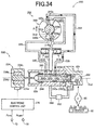
- FIG. 1 is a view schematically showing a construction of a vehicle drive-force transmitting apparatus 20 which is to be provided in a vehicle and which includes an electronic control unit 170 according to an embodiment of the invention.
- FIG. 1 shows also a construction of a hydraulic variable valve-timing apparatus 200 including an electronic control unit 270 according to another embodiment of the invention.
- the drive-force transmitting apparatus 20 includes a torque converter 12 connected to a vehicle engine 10, a vehicle automatic transmission 14, a differential gear device 16 and a hydraulic control unit 18 configured to control shifting actions of the automatic transmission 14, in addition to the electronic control unit 170 configured to control the hydraulic control unit 18.
- a drive force outputted from the engine 10 is transmitted to drive wheels (not shown) of the vehicle via, for example, the torque converter 12, the automatic transmission 14, the differential gear device 16 and right and left axles 22.
- the torque converter 12 includes a pump impeller 28 connected to a crank shaft 26 of the engine 10, a turbine impeller 32 which is connected to an input shaft 30 of the automatic transmission 14 and to which the drive force is transmitted via a fluid under pressure, a stator impeller 38 connected through a one-way clutch 34 to a housing 36 as a non-rotary member, and a lock-up clutch 40 configured to directly connect the pump impeller 28 and the turbine impeller 32 through a damper (not shown).
- the automatic transmission 14 is a multi-speed transmission configured to establish four forward gear positions and one reverse gear position.
- the automatic transmission 14 includes, in addition to the input shaft 30, a planetary gear unit 44 of Ravignawx type, a ring gear 48 that is to be rotated together with a ring gear 46 of the planetary gear unit 44, and a counter shaft 50 serving as an output shaft configured to transmit the drive force between the ring gear 48 and the differential gear device 16.
- the planetary gear unit 44 consists of a planetary gear device 52 of single pinion type and a planetary gear device 54 of double pinion type, wherein a carrier 56 and the ring gear 46 are rotary elements common to the planetary gear devices 52, 54.
- the planetary gear device 52 includes rotary elements in the form of a sun gear 58, planetary gears 60 attached to the carrier 56, and the ring gear 46.
- the planetary gear device 54 includes rotary elements in the form of a sun gear 62 and first and second pinions 64 66, such that the first and second pinions 64, 66 are connected integrally to each other and are rotatably held by the carrier 56.
- the vehicle drive-force transmitting apparatus 20 is constructed substantially symmetrically about the axis CL1 (corresponding to an axis of the input shaft 30), except the torque converter 12 and the counter shaft 50 of the automatic transmission 14, so that a lower side of the axis CL1 is not shown in FIG. 1 .
- Each of the clutches C1, C2, C3 and the brakes B1, B2, B3 as the hydraulic friction engagement devices is constituted by, for example, a multiple-disc clutch or a band brake including one band or two bands that wound in respective opposite directions.
- FIG. 2 is a table explaining a combination of each of gear positions of the automatic transmission 14 shown in FIG. 1 and a corresponding one or ones of the hydraulic friction engagement devices of the automatic transmission 14, which are to be engaged to establish the each of the gear positions in the automatic transmission 14.
- "O" indicates an operated or engaged state of the engagement devices
- blank indicates a non-operated or released state of the engagement devices.
- a shift-up action from the second gear position to the third gear position in the drive range is executed by causing the clutch C2 to be placed in the engaged state and maintaining the engaged state of the clutch C1.
- a shift-down action from the fourth gear position to the third gear position is executed by causing the clutch C1 to be placed in the engaged state and causing the brake B1 to be placed in the released state, such that the engaging action of the clutch C1 and the releasing action of the brake B1 are executed by a so-called "clutch-to-clutch shifting", namely, executed in an overlap state or an underlap state.
- the hydraulic control unit 18 incudes first and second electromagnetic opening/closing valves SV1, SV2 that are to be controlled to establish the gear positions in the automatic transmission 14, two linear solenoid valves SLT, SLU and an oil temperature sensor 88.
- the linear solenoid valve SLT is configured to generate a control hydraulic pressure PS[MPa] whose magnitude corresponds to an engine load, i.e., a throttle opening degree TA[%] detected by a throttle opening-degree sensor 76.
- the linear solenoid valve SLU is configured to generate a hydraulic pressure for controlling, for example, an operation state of the lock-up clutch 40, namely, for establishing a frictional engagement of the clutch 40, releasing the frictional engagement and controlling a slipping amount of the clutch 40.
- the oil temperature sensor 88 serves as a working-fluid temperature detecting device configured to detect a working-fluid temperature Thoil[°C] in the hydraulic control unit 18. It is noted that the control hydraulic pressure PS corresponds to "signal pressure" recited in the appended claims.
- the electronic control unit (ECU) 170 includes a so-called microcomputer incorporating a CPU, a ROM, a RAM and an input-output interface (not shown).
- the electronic control unit 170 is configured to control the hydraulic friction engagement devices (such as the clutches C1, C2, C3 and the brakes B1, B2, B3) and the lock-up clutch 40 that are included in the drive-force transmitting apparatus 20, by causing the CPU to process various input signals, according to control programs stored in the ROM, while utilizing a temporary data-storage function of the RAM.
- the electronic control unit 170 corresponds to "control apparatus" recited in the appended claims.
- the electronic control unit 170 receives various input signals from various sensors provided in the vehicle, such as: an output signal of the above-described throttle opening-degree sensor 76 configured to detect the throttle opening degree TA in an intake pipe (not shown) of the engine 10; an output signal of an engine speed sensor 78 configured to detect an engine rotational speed Ne[rpm]; an output signal of an input-shaft speed sensor 80 configured to detect an input-shaft rotational speed Nin[rpm]; an output signal of a running speed sensor 82 configured to detect a counter-shaft rotational speed Nc[rpm], i.e., a vehicle running speed Vc[km/h]; an output signal of a shift position sensor 86 configured to detect an operation position Pst of the above-described shift lever 84, namely, detect in which one of the parking range, the reverse range, the neutral range, the drive range, the second speed range and the low speed range the shift lever 84 is placed; an output signal of the above-described oil temperature sensor 88 configured to detect the temperature Thoil
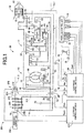
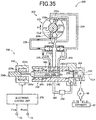
- FIG. 3 a block diagram schematically showing a main construction of the hydraulic control unit 18 configured to control the automatic transmission 14 shown in FIG. 1 .
- a hydraulic pump 90 is to be driven or operated by the engine 10 so as to suck the working fluid returned trough a strainer 92 and to supply the working fluid to a line-pressure generating device 100.
- the line-pressure generating device 100 regulates the working fluid supplied from the hydraulic pump 90, to a line pressure PL[MPa] that corresponds to the engine load, and then outputs the regulated line pressure PL as an original pressure of each of the hydraulic friction engagement devices in the form of the clutches C1, C2, C3 and the brakes B1, B2, B3, to a shift valve device 102.
- a manual valve 104 is mechanically connected to the shift lever 104, and selects a destination to which the line pressure PL is to be supplied, such that the selected destination is dependent on the operation position Pst of the shift lever 84.
- the hydraulic pressure corresponding to the operation position Pst of the shift lever 84 e.g., a reverse-range pressure, a drive-range pressure, a second-range pressure or a low-range pressure is outputted to the shift valve device 102.
- Each of the first electromagnetic opening/closing valve SV1 and the second electromagnetic opening/closing valve SV2 outputs an output pressure that is controlled by the electronic control unit 170 to select one of the gear positions, and the output pressure is supplied to the shift valve device 102.
- the shift valve device 102 includes a 1-2 shift valve, a 2-3 shift valve and a 3-4 shift valve (not sown) that are to be switched for a shifting action, based on the hydraulic pressure corresponding to the operation position Pst of the shift lever 84 and supplied from the manual valve 104 and also the output pressure supplied from each of the first and second electromagnetic opening/closing valve SV1, SV2.
- the shift valve device 102 supplies an engaging pressure to each of a corresponding one or ones of the hydraulic friction engagement devices in the form of the clutches C1, C2, C3 and the brakes B1, B2, B3, in accordance with the corresponding combination indicated in FIG. 2 .
- the clutches C1, C2, C3 and the brakes B1, B2 are connected to a C1 accumulator AC1, a C2 accumulator AC2, a C3 accumulator AC3, a B1 accumulator AB1 and a B2 accumulator AB2, respectively, such that an increase of the supplied engaging pressure, i.e., an engaging torque in each of these hydraulic friction engagement devices is alleviated.
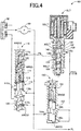
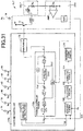
- FIG. 4 is a hydraulic circuit diagram showing the line-pressure generating device 100 shown in FIG. 3 .
- a line-pressure regulator valve 110 includes: a plunger 112; a spool valve body 114 which is in contact with the plunger 112 and which is axially movable so as to selectively allow and inhibit communication between an input port 110b and an output port 110d; and a spring 118 that constantly forces or biases the spool valve body 114 through a spring receiver plate 116 in a connection inhibiting direction that causes the spool valve body 114 to inhibit the communication between the input port 110b and the output port 110d.
- the line-pressure regulator valve 110 regulates the working fluid supplied from the hydraulic pump 90 through the input port 110b, based on the control hydraulic pressure PS supplied from the linear solenoid valve SLT through an input port 110a, such that the working fluid is regulated to the line pressure PL that corresponds to a load of the engine 10.
- the hydraulic pressure which is supplied through the input port 110b, is supplied as a feedback hydraulic pressure.
- the line pressure PL is expressed by equation (7) given below, wherein "WREG[N]” represents a biasing force of the spring 118, “AREG1[mm 2 ]” represents a annular-shaped pressure-receiving area of a land 120 of the spool valve body 114, and “AREG2[mm 2 ]” represents a pressure receiving area of the plunger 112 on which the hydraulic pressure forcing the spool valve body 114 in the above-described connection inhibiting direction acts.
- the equation (7) indicates that the line pressure PL is generated in proportion with the control hydraulic pressure PS.
- the line pressure PL is regulated to have a magnitude corresponding to the engine load.
- the linear solenoid valve SLT includes: a spool valve body 132 configured to selectively allow and inhibit communication between an input port 130a and an output port 130b; and a spring 134 that constantly forces or biases the spool valve body 132 in a connection allowing direction that causes the spool valve body 132 to allow the communication between the input port 130a and the output port 130b.
- a constant hydraulic pressure PSOL[MPa] is supplied through the input port 130a, and the supplied constant hydraulic pressure PSOL is regulated to the control hydraulic pressure PS corresponding to a driving current i(t)[A] of the linear solenoid SSLT which is controlled by the electronic control unit 170, so that the regulated control hydraulic pressure PS is outputted through the output port 130b.
- the control hydraulic pressure PS (or a change characteristic with respect to a thrust FI) is expressed by equation (8) given below, wherein “FI[N]” represents a thrust, as a driving signal SD1 corresponding to the driving current i(t) of the linear solenoid SSLT, which forces the spool valve body 132 in a connection inhibiting direction that causes the spool valve body 132 to inhibit the communication between the input port 130a and the output port 130b, “WSLT[N]” represents a biasing force of the spring 134, and “ASLT[mm 2 ]” represents an annular-shaped pressure-receiving area of a land 136 of the spool valve body 132.
- a feedback fluid chamber 140 defined between the land 136 and a land 138 is in communication with the output port 130b via a fluid passage 142, so that a hydraulic pressure acting on the annular-shaped pressure-receiving area of the land 136 corresponds to the control hydraulic pressure PS.
- the thrust FI has a magnitude that is proportional with the driving current i(t) of the linear solenoid SSLT.
- PS WSLT / ASLT ⁇ FI / ASLT
- a pressure reducing valve 150 includes a spool valve body 152 configured to selectively allow and inhibit communication between an input port 150a and an output port 150b; and a spring 154 that constantly forces or biases the spool valve body 152 in a connection allowing direction that causes the spool valve body 152 to allow the communication between the input port 150a and the output port 150b.
- the pressure reducing valve 150 regulates the line pressure PL supplied thereto through the input port 150a, to the constant hydraulic pressure PSOL, and outputs the constant hydraulic pressure PSOL through the output port 150b.
- the constant hydraulic pressure PSOL outputted through the output port 150b is supplied to the linear solenoid valve SLT and the linear solenoid valve SLU.
- the constant hydraulic pressure PSOL is expressed by equation (9) given below, wherein "AMOD[mm 2 ]” represents an area of a pressure-receiving portion of the spool valve body 152, which is in communication with the input port 150c, and "WMOD[N]” represents a biasing force of the spring 154.
- PSOL WMOD / AMOD
- FIG. 5 is a functional block diagram showing an equivalent circuit of the linear solenoid SSLT shown in FIG. 4 , a drive circuit DRV of the linear solenoid SSLT and the electronic control unit 170a for the linear solenoid SSLT, which is constructed according to an arrangement of the embodiment of the invention.
- a portion of a feedback controller portion 176a, which is to be subjected to a control is surrounded by one-dot chain line, and the portion subjected to the control has a construction without a feedthrough term.
- FIG. 6 is a functional block diagram showing the equivalent circuit of the linear solenoid SSLT shown in FIG.
- FIG. 6 a portion of a feedback controller portion 176b, which is to be subjected to a control, is surrounded by one-dot chain line, and the portion subjected to the control has a construction with a feedthrough term.
- the functional block diagrams shown in FIGS. 5 and 6 are identical with each other except the feedback controller portion 176a shown in FIG. 5 and the feedback controller portion 176b shown in FIG. 6 that are different from each other.
- the electronic control unit 170a and the electronic control unit 170b are examples of the electronic control unit 170, and the feedback control system of the electronic control unit 170 is designed in accordance with ILQ design method.
- the term "feedback control system” is interpreted to mean a construction configured to execute an automatic control by a feedback control, and is represented by, for example, a control block diagram shown in the feedback controller portion 176a in FIG. 5 and a control block diagram shown in the feedback controller portion 176b in FIG. 6 .
- the linear solenoid SSLT has electrical characteristics that are represented by a RL series circuit of an equivalent inductance Ls[H] and an equivalent resistance Rs[ ⁇ ]. It is noted that an ON resistance of a drive transistor Tr (described below) is included in the equivalent resistance Rs.
- the drive circuit DRV for the linear solenoid SSLT includes: a terminal Bt through which a battery voltage Pb[V] is supplied as a power supply voltage; a drive transistor Tr; a detection resistance Rd[ ⁇ ]; an operational amplifier AMP and an A/D converter ADC.
- the driving current i(t) is caused to flow through the linear solenoid SSLT by the battery voltage Pb.
- the detection resistance Rd[ ⁇ ] is connected in series with the linear solenoid SSLT, so that the driving current i(t) flowing through the linear solenoid SSLT is taken as a voltage difference between opposite ends of the detection resistance Rd.
- the taken voltage difference is amplified by the operational amplifier AMP, and is then converted into a digitized signal in the form of a current signal Iact representing the actual driving current i(t).
- the current signal Iact is inputted to the electronic control unit 170b.
- the electronic control unit 170b includes, in addition to the feedback controller portion 176b, a command-value setting portion 172, a parameter storing portion 174 and a PWM portion 178.
- the command-value setting portion 172 sets a current command value r(t) representing a control target value in the form of an average value of the driving current i(t) of the linear solenoid SSLT, in accordance with a predetermined running map, based on the signal indicative of the throttle opening degree TA, the signal indicative of the engine rotational speed Ne, the signal indicative of the input-shaft rotational speed Nin, the signal indicative of the counter-shaft rotational speed Nc, i.e., the vehicle running speed Vc and the signal indicative of the operation position Pst of the shift lever 84.
- the command-value setting portion 172 outputs the current command value r(t) that is supplied to the feedback controller portion 176b.
- Parameters which are applied to the feedback control system as described below, are stored in the parameter storing portion 174 in a stage of production of the parameter storing portion 174.
- the feedback controller portion 176b causes the current command value r(t) supplied from the command-value setting portion 172, to be subjected to the feedback control using the current signal Iact representing the actual driving current i(t), and outputs, as an output y, the current command value r(t) subjected to the feedback control.
- the output y is outputted to the PWM portion 178.
- the output y is a signal representing a duty ratio dependent on an average driving current i(n ⁇ ) as a controlled variable that is described below.
- the PWM portion 178 generates a PWM (pulse width modulation) signal based on the output y supplied from the feedback controller portion 176b.
- the PWM portion 178 outputs the generated PWM signal to a gate electrode of the drive transistor Tr, and executes the ON-OFF control of the drive transistor Tr.
- An input voltage vin(t)[V] inputted to the linear solenoid SSLT through a side of the drive transistor Tr is controlled by the duty ratio of the ON-OFF control of the drive transistor Tr, whereby the driving current i (t) of the linear solenoid SLT is controlled.
- the nominal value is an average value of each of the characteristic values of the resistances and inductance.
- the actual characteristic value (hereinafter referred to as an actual value) varies depending on production variation and temperature change.
- the battery voltage Pb is 15[V]
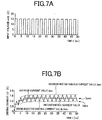
- FIGS. 7A and 7B are views explaining change of an instantaneous value of the driving current i(t) where the drive transistor Tr shown in FIG. 6 is subjected to the ON-OFF control with supply of the PWM signal, and also change of an average lave of the instantaneous value of the driving current i(t) in each driving period ⁇ .
- FIGS. 7A and 7B show a case in which the PWM signal whose duty ratio is 50% starts to be inputted to the drive transistor Tr at a point 0[s] of time.
- the drive transistor Tr is ON in a fist half (50%) of each driving period ⁇ , and is OFF in a second half (50%) of each driving period ⁇ .
- FIG. 7A shows change of the input voltage vin(t) with respect to time
- FIG. 7B shows change of the driving current i(t) with respect to time.
- the input of 15[V] and the input of 0[V] are alternately made to the linear solenoid SSLT as the input voltage vin(t) in every half (about 1.67[ms]) of each driving period ⁇ .
- one of two broken lines is a line that connects minimum instantaneous current values Imin appearing in the respective driving periods ⁇
- the other of the two boken lines is a line that connects maximum instantaneous current values Imax appearing in the respective driving periods ⁇ .
- the instantaneous value of the driving current i(t), which flows through the linear solenoid SSLT, is fluctuated between the minimum instantaneous current value Imin and the maximum instantaneous current value Imax in each driving period ⁇ , and is gradually increased with each of the minimum instantaneous current value Imin and the maximum instantaneous current value Imax being converged to a constant value after a certain length of time elapses.
- the average lave of the instantaneous value of the driving current i(t) is also gradually increased with the increases of each of the minimum instantaneous current value Imin and the maximum instantaneous current value Imax, and is converged to a constant value after a certain length of time elapses.
- the average Iavec is an average of the instantaneous value of the driving current i(t) in the converged state.
- the minimum instantaneous current values Imin is a minimum of the instantaneous value of the driving current i(t) in the converged state. It is noted that the "converged state” is interpreted to mean a state in which the minimum instantaneous current value Imin and the average lave of the instantaneous value of the driving current i(t) become constant or substantially constant without change or substantial change.
- FIG. 8 is a functional block diagram showing a design process 190 of the feedback control system in the electronic control unit shown 170b shown in FIG. 6 .
- the design process 190 includes steps of "electric circuit approximation 190a”, “first formulation 190b", “second formulation 190c”, “recurrence equation derivation 190d”, “recurrence equation solution 190e”, “linearization by approximation equation 190f', “transfer function derivation by ILQ design method 190g” and "parameter input 190h”.
- steps of these steps may be implemented by either a human operator or an electronic computer such as AI (Artificial Intelligence).
- the electronic computer constitutes portions configured to implement the respective steps.
- the electronic control unit shown 170b may be interpreted to include an electric circuit approximating portion 190a, a first formulating portion 190b, a second formulating portion 190c, a recurrence-equation deriving portion 190d, a recurrence-equation solving portion 190e, a linearizing portion 190f, a transfer-function deriving portion 190g and a parameter inputting portion 190h, which are configured to implement the respective steps.
- the step of the "electric circuit approximation 190a”, which is implemented first, is a step of approximating a series circuit including a resistance Rz[ ⁇ ] and an inductance L[H], to the electric circuit of the linear solenoid SSLT through which the driving current i(t) flows, wherein the resistance Rz is a sum of the equivalent resistance Rs of the linear solenoid SSLT and the detection resistance Rd, and the inductance L is synonymous with the equivalent inductance Ls of the linear solenoid SSLT.
- the step of the "first formulation 190b", which is implemented next, is a step of formulating a circuit equation related to the instantaneous value of the driving current i(t) that flows in the approximated series circuit.
- the step of the "second formulation 190c”, which is implemented next, is a step of formulating an equation related to the controlled variable in control of the driving current i(t).
- the step of the "recurrence equation derivation 190d”, which is implemented next, is a step of deriving a recurrence equation from the equation related to the controlled variable.
- the step of the "recurrence equation solution 190e”, which is implemented next, is a step of obtaining a solution of the recurrence equation, by solving the recurrence equation.
- the step of "linearization by approximation equation 190f', which is implemented next, is a step of linearizing the solved recurrence equation by an approximation equation.
- the step of "transfer function derivation by ILQ design method 190g” which is implemented next, is a step of deriving a transfer function by using the recurrence equation that has been linearized and solved.
- the "parameter input 190h”, which is implemented next, is a step of writing or inputting parameters, which are to be applied to the derived transfer function, into the parameter storing portion 174 of the electronic control unit 170. Specific contents of these steps will be described below.
- FIG. 9 is a flow chart showing the design process of the feedback control system in the electronic control unit 170b shown in FIG. 6 .
- steps of the design process each of the steps except step S70 is started to be implemented and is implemented once in a stage of design process.
- Step S70 is implemented once when the parameters are stored into the electronic control unit 170b provided in the drive-force transmitting apparatus 20 of each of vehicles.
- step S10 corresponding to the step of the "electric circuit approximation 190a"
- the electric circuit of the linear solenoid SSLT, through which the driving current i(t) flows is approximated by the series circuit of the resistance Rz and the inductance Ls.
- Step S10 is followed by step S20.
- equation (10) in the form of a differential equation is formulated as the circuit equation related to the electric circuit which is constituted by the linear solenoid SSLT and the drive circuit DRV and though which the driving current i(t) flows, wherein the input voltage inputted to the linear solenoid SSLT through the side of the drive transistor Tr is represented by "vin(t)". It is noted that equation (10) is identical with the above-described equation (1). Step S20 is followed by step S30.
- Equation (15) related to the driving current i(t) is established by obtaining a step response of the driving current i(t) in response to a step input of the input voltage vin(t) at a point 0[s] of time in the above transfer function G p (s), wherein "Pb” represents the battery voltage as described above.
- Equation (16) related to the average driving current i( ⁇ ) in the first period is established in accordance with superposition principle, wherein ⁇ 1 / ⁇ * 100[%] corresponds to the duty ratio.
- Equation (17) related to the average driving current i( ⁇ ) is obtained by transforming the equation (16). It is noted that an ON time ⁇ 1 [s] represents a length of time for which the drive transistor Tr is controlled to be ON, and an OFF time ⁇ 2 [s] represents a length of time for which the drive transistor Tr is controlled to be OFF. The OFF time ⁇ 2 is obtained by subtracting the ON time ⁇ 1 from the driving period ⁇ .
- equation (18) related to the average driving current i(2 ⁇ ) in the second period is established. Since equation (19) is established, equation (20) related to the average driving current i(2 ⁇ ) is established. Further, by substantially the same equation transform as the derivation of the average driving current i( ⁇ ) and average driving current i(2 ⁇ ), equation (21) in the form of a recurrence equation is derived. It is noted that the equation (21) is identical with the above-described equation (3). Step S40 is followed by step S50.
- step S50 corresponding to the step of the "recurrence equation solution 190e"
- the recurrence equation is solved so that the solution related to the controlled variable is obtained.
- FIG. 10 is a result of simulation in which the duty ratio is changed from 0% to 50% at a point 0[s] of time, and shows time response as the result of the simulation, which is in accordance with the equation (28).
- X marks indicate the time response of the driving current i(t) which is in accordance with the equation (28), and broken line indicates a converged value of the driving current i(t).
- the converged value after a sufficient length of time has elapsed, namely, the converged driving current a ⁇ with n ⁇ in the equation (28) is represented as in equation (29).
- equation (30) related to the converged driving current a ⁇ is established.
- the converged driving current a ⁇ after the sufficient length of time has elapsed corresponds to "duty ratio * battery voltage Pb / resistance Rz", as indicated in the above-described equation (30), so that it is understood that the converged driving current a ⁇ has a linear relationship with respect to the duty ratio.
- Step S50 is followed by step S60.
- step S60 corresponding to steps of the "linearization by approximation equation 190f' and "transfer function derivation by ILQ design method 190g", the solved recurrence equation is linearized by the approximation equation, and the transfer function is derived.
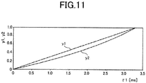
- FIG. 11 is a view showing a relationship between the output y1 and ON time ⁇ 1 and a relationship between the output y2 and the ON time ⁇ 1 , wherein the output y1 has a linear relationship with respect to possible values of the ON time ⁇ 1 while the output y2 has a non-linear relationship with respect to the possible values of the ON time ⁇ 1 . From the result shown in FIG.
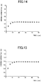
- FIGS. 12-16 The step response of the average driving current a n in response to the step input of the input voltage vin(t) at the point 0[s] is shown in FIGS. 12-16 in which X marks indicate the average driving current a n in accordance with the equation (28) that is a non-linear model equation, black circle marks indicate the average driving current a n in accordance with the equation (34) that is a linear model equation, and broken line indicates converged value of the average driving current a n .
- FIG. 12-16 The step response of the average driving current a n in response to the step input of the input voltage vin(t) at the point 0[s] is shown in FIGS. 12-16 in which X marks indicate the average driving current a n in accordance with the equation (28) that is a non-linear model equation, black circle marks indicate the average driving current a n in accordance with the equation (34) that is a linear model equation, and broken line indicates converged value of the average driving current a n
- FIG. 12 is a result of simulation in which the duty ratio is set to 5%, and shows the step response as the result of the simulation in case of the non-linear model equation and also in case of the linear model equation.
- FIG. 13 is a result of simulation in which the duty ratio is set to 10%, and shows the step response as the result of the simulation in case of the non-linear model equation and also in case of the linear model equation.
- FIG. 14 is a result of simulation in which the duty ratio is set to 20%, and shows the step response as the result of the simulation in case of the non-linear model equation and also in case of the linear model equation.
- FIG. 15 is a result of simulation in which the duty ratio is set to 30%, and shows the step response as the result of the simulation in case of the non-linear model equation and also in case of the linear model equation.
- FIG. 16 is a result of simulation in which the duty ratio is set to 50%, and shows the step response as the result of the simulation in case of the non-linear model equation and also in case of the linear model equation.
- the equation (33) as the approximation equation provides a satisfactory approximation also in the step response.
- Equation (34) a transfer function G(s) (continuous time model) of the system is obtained.
- G(s) continuous time model
- Equation (36) is obtained by applying Laplace transform to both sides of the equation (35).
- the transfer function G 1 (s) is represented by equation (37).
- equation (34), (35), equations (38), (39), (40) By comparing coefficients in the equations (34), (35), equations (38), (39), (40) are established.
- a coefficient "(A-B)T" of "s" constituting a numerator of a right side of the equation (37) corresponds to equation (41), so that the transfer function G(s) is represented by equation (42).
- the transfer function G(s) is represented by equation (43), which is obtained by applying the above-described specification values into the equation (42).
- FIG. 17 is a result of simulation in which the duty ratio is set to 50%, and shows the step response as the result of the simulation in case of the equation (42) as a continuous model equation and also in case of the equation (28) as a discrete model equation.
- solid line indicates the driving current i(t) in accordance with from the continuous model equation
- X marks indicate the driving current i(t) in accordance with the discrete model equation
- broken line indicates the converged value of the driving current i(t).
- the values calculated by the equation (28) as the discrete model equation are the same as those sampled from the step response calculated by the equation (42) as the continuous model equation in the respective driving periods ⁇ .
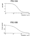
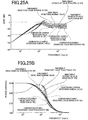
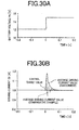
- FIGS. 18A and 18B show Bode diagram of the transfer function G(s) of the continuous model equation.
- FIG. 18A shows frequency characteristic of a gain of the transfer function G(s).
- FIG. 18B shows frequency characteristic of a phase of the transfer function G(s). From a transmission representation of the transfer function G(s) of the equation (42), it is understood that the transfer function G(s) is formed by a parallel combination of a primary delay block and a gain block that has no dynamics.
- Equation (45) The transfer function G(s), which is equation (45), is represented by a state space representation (controllability canonical form) in the form of equations (44). With a steady-state gain of the input and output being taken into consideration, equations (46), (47) using a state variable x1 are established.
- E ⁇ 0.285263703450086 ⁇
- step S70 is implemented.
- step S70 corresponding to the step of "parameter input 190h"
- the parameters of the feedback control system are written or inputted into the parameter storing portion 174 of the electronic control unit 170b.
- the input of the parameters into the parameter storing portion 174 is made in process of production of each vehicle.
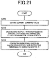
- the process of determining the parameters of the feedback control system will be described below.
- the control target value of the driving current i(t) of the linear solenoid SSLT is determined by using the transfer function that can be represented by a mathematical expression.
- the process shown in the flow chart of FIG. 9 is completed with the implementation of step S70.
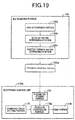
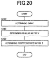
- FIG. 19 is a functional block diagram showing a process of determining the parameters of the feedback control system in accordance with ILQ design method in the electronic control unit 170b shown in FIG. 6 .
- An ILQ designing portion 192 is used at the step of "transfer function derivation by ILQ design method 190g" shown in FIG. 8 .
- the ILQ designing portion 192 is a computer aided design system (CAD: Computer Aided Design) as a design tool for executing calculations in the ILQ design method (Inverse Linear Quadratic design method), and includes a gain determining portion 192a, a regular-matrix determining portion 192b, a positive-definite-matrix determining portion 192c, a parameter storing portion 192d and a parameter inputting portion 192e.
- the ILQ design method which is referred also to as an inverse-linear quadratic equation optimal control system design method, is an optimal servo system design method to which a result of an inverse problem of an optimal regulator problem (LQ problem) based on a modern control theory is skillfully applied.
- the solution of the LQ problem can be derived by a simple pole assignment without weighting.
- the ILQ design method is disclosed in details in a plurality of documents (e.g., title: Robust Control; authors: Hidenori Kimura, Takao Fujii, Takehiro Mori; published by Korona-sha in 1994; see pages 141-153 ).
- the gain determining portion 192a determines a gain K in the feedback control system. The determination of the gain K in accordance with the ILQ design method will be described specifically below. After having determined the gain K, the gain determining portion 192a outputs a command signal to the regular-matrix determining portion 192b. It is noted that the gain K corresponds to one of "parameters" recited in the appended claims.
- the regular-matrix determining portion 192b determines a regular matrix V in the feedback control system. The determination of the regular matrix V in accordance with the ILQ design method will be specifically described below. After having determined the regular matrix V, the regular-matrix determining portion 192b outputs a command signal to the positive-definite-matrix determining portion 192c.
- the positive-definite-matrix determining portion 192c determines a positive definite matrix ⁇ in the feedback control system.
- the determination of the positive definite matrix ⁇ in accordance with the ILQ design method will be de described specifically below.
- the positive-definite-matrix determining portion 192c outputs the parameters such as the gain K, regular matrix V and positive definite matrix ⁇ , to the step of "parameter input 190h" shown in FIG. 8 . It is noted that the positive definite matrix ⁇ corresponds to one of "parameters" recited in the appended claims.
- the parameters such as the gain K, regular matrix V and positive definite matrix ⁇ are written or inputted into the parameter storing portion 174 of the electronic control unit 170b.
- R (n-m) ⁇ (n-m) represents a set of real number matrixes of (n-m) ⁇ (n-m) order
- R (n-m) ⁇ m represents a set of real number matrixes of (n-m) ⁇ m order
- R m ⁇ (n-m) " represents a set of real number matrixes of m ⁇ (n-m) order.
- R m ⁇ m represents a set of real number matrixes of m ⁇ m order.
- the regular matrix V is determined.
- the regular matrix V is constituted by an identity matrix, since the regular matrix V is not particularly restricted as long as it is a regular matrix.
- the positive definite matrix ⁇ is determined based on equation (55) that is a linear matrix inequality. Specifically, a matrix, which is not smaller than ⁇ min , is selected as the positive definite matrix ⁇ , wherein ⁇ min is a minimum positive definite matrix that makes a positive definite matrix Y 1 (> 0) feasible in the equation (55).
- controllable means capable of moving a controlled object desirably by a current input.
- observable means capable of estimating a value of a state variable in a system through only an input and an output of a currently installed sensor.
- Equation (61) represents an extended deviation system of an input v expressed by equation (59) and an output y e expressed by equation (60), while an evaluation function J is expressed by equation (62).
- the control block diagram is realized by a structure of the feedback controller portion 176a shown in FIG. 5 described above.
- the results from the above-described equations (48)-(55) can be applied substantially directly to an extended system constituted by A e , B e , C e . Therefore, the optimal control rule K e for the extended system is parameterized as equation (65). With the equation (65) being applied to the equation (64), the optimal control rule K e is expressed by equation (66).
- the control block diagram corresponds to a structure of the feedback controller portion 176b shown in FIG. 6 described above. However, the calculation is simplified since each system matrix of the extended system has a partial zero matrix.
- K e V ⁇ 1 ⁇ V KI
- K e V ⁇ 1 ⁇ V K F 0 K I 0
- the regular matrix V is determined.
- the regular matrix V is constituted by an identity matrix, for example, for simplification.
- the positive definite matrix ⁇ is determined based on equation (69) that is a linear matrix inequality. Specifically, a matrix, which is not smaller than ⁇ min , is selected as the positive definite matrix ⁇ , wherein ⁇ min is a minimum positive definite matrix that makes a positive definite matrix Y (> 0) feasible in the equation (69).
- ⁇ min is a minimum positive definite matrix that makes a positive definite matrix Y (> 0) feasible in the equation (69).
- the gain K is obtained by pole assignment, and a positive definite matrix ⁇ ( ⁇ ) is set to a positive-definite diagonal matrix that is larger than a certain lower limit.
- a assigned pole when ⁇ is set to -1/0.0282*3, for the purpose of causing the control target value to follow a value dulled or moderated by a time constant Tf of 28.2[ms].
- the gains K F , K I (see FIG. 5 ), which are equivalently transformed to an integral-type servo system, are obtained in equation (72). It is noted that A e , B e , C e are expressed by equations (73).
- An optimality-assuring lower-limit ⁇ min is obtained as a minimum positive definite matrix ⁇ min (> 0) that makes a positive definite matrix Y 1 (> 0) feasible in the equation (75) in which "Ak”, “Bv”, “Kv” are expressed by equations (74), and the optimality-assuring lower-limit ⁇ min is expressed by equation (76).
- Equations (77), (78) are established as is understood from FIG. 6 that shows the control block diagram of the feedback controller portion 176b that is designed in accordance with ILQ design method in the present embodiment. Equation (79) is obtained by applying the equation (78) to the equation (77). However, the equation (78) is transformed to equations (81) in view of equation (80). Equation (82) is obtained by applying the equations (81) to the equation (79).
- Equation (82) is transformed to equation (83), by solving "Y(s)".
- the transfer function G yd (s) of the feedback controller portion 176b according to the present embodiment, which is shown in FIG. 6 is expressed by equation (84).
- FIG. 20 is a flow chart showing a process of determining the parameters of the feedback control system in the electronic control unit 170b shown in FIG. 6 , in accordance with the ILQ design method.
- the process shown by the flow chart in FIG. 20 is started to be executed and is executed once in a stage of design process of the feedback control system.
- step S100 corresponding to function of the gain determining portion 192a, the gain K is calculated and determined. Then, step S100 is followed by step S110.
- step S110 corresponding to function of the regular-matrix determining portion 192b, the regular matrix V is calculated and determined. Then, step S110 is followed by step S120.
- step S120 corresponding to function of the positive-definite-matrix determining portion 192c, the positive definite matrix ⁇ is calculated and determined.
- the process shown in the flow chart of FIG. 20 is completed with the implementation of step S120.
- the feedback controller portion 176b calculates the output y, by applying a value obtained by subtracting the current signal Iact (that is supplied from the A/D converter ADC) from the current command value r(t) (that is supplied from the command-value setting portion 172), into the feedback control system in which the parameters such as the gain K and the positive definite matrix ⁇ , which are stored in the parameter storing portion 174, are applied. Then, the feedback controller portion 176b outputs the calculated output y to the PWM portion 178.
- FIG. 21 is a flow chart showing a process of determining the controlled variable in the feedback control system in the electronic control unit 170. For example, a change of an operation state of the vehicle triggers a start of the process shown in the flow chart of FIG. 21 .
- step S200 corresponding to function of the command-value setting portion 172, the current command value r(t) representing the control target value in the form of the average value of the driving current i(t) of the linear solenoid SSLT is set. Then, step S200 is followed by step S210.
- step S210 corresponding to functions of the parameter storing portion 174 and the feedback controller portion 176b, a deviation e of the current signal Iact of the current signal Iact as an observed value of the output y is subjected to a calculation made by the feedback control system represented by the control block diagram described in the feedback controller portion 176b shown in FIG. 6 , whereby the output y is calculated. Then, step S210 is followed by step S220.
- step S220 corresponding to function of the PWM portion 178, the PWM signal is generated based on the output y, and is outputted to the gate electrode of the drive transistor Tr.
- the process shown in the flow chart of FIG. 21 is completed with the implementation of step S220.
- FIG. 22 is a functional block diagram showing the equivalent circuit of the linear solenoid SSLT, the drive circuit DRV of the linear solenoid SSLT and an electronic control unit 370 of the linear solenoid SSLT.
- the electronic control unit 370 which is according to a conventional example, is designed by a two-degree-of-freedom control system.
- the electronic control unit 370 according to the comparative example is substantially the same as the electronic control unit 170 according to the above-described first embodiment.
- the electronic control unit 370 and the electronic control unit 170 are different from each other in that its feedback controller portion 376 is designed by the two-degree-of-freedom control system in the comparative example while each of the feedback controller portions 170a, 170b has a construction designed by the ILQ design method in the first embodiment. Therefore, the differences will be mainly described, and the same reference signs as used in the above-described first embodiment will be used to identify the functionally corresponding elements, with descriptions thereof being omitted as needed.
- the electronic control unit 370 includes the above-described command-value setting portion 172, parameter storing portion 174, PWM portion 178 and feedback controller portion 376.
- the feedback control system In the parameter storing portion 174, parameters, which are applied to the feedback control system as described above, are stored in a stage of production of the parameter storing portion 174. It is noted that "the feedback control system" according to the comparative example is represented by a control block diagram described in the feedback controller portion 376 shown in FIG. 22 .
- the feedback controller portion 376 causes the current command value r(t) supplied from the command-value setting portion 172 to be subjected to the feedback control using the current signal Iact representing the actual driving current i(t), and outputs, as the output y, the current command value r(t) subjected to the feedback control.
- the output y is outputted to the PWM portion 178.
- the output y is a signal representing the duty ratio dependent on the average driving current i(n ⁇ ) as a controlled variable that is described below.
- the final manipulated variable is subjected to a calculation of the transfer function G p (s), whereby the average driving current i(n ⁇ ) as the output y, i.e., the controlled variable is determined.
- d represents a disturbance caused when the spool valve body 132 is moved by a hydraulic vibration or the like.
- the disturbance d is constituted by, for example, a counter electromotive force that is generated in the linear solenoid SSLT by movement of an iron core within a coil as the linear solenoid SSLT, which is made by movement of the spool valve body 132.
- the feedforward gain K ff is set to 50, it is preferable that the feedforward gain K ff is set based on the battery voltage Pb and the resistance Rz (that is a sum of the equivalent resistance Rs and the detection resistance Rd), for example, such that the feedforward gain K ff is set to [1/ ⁇ (Pb)/(Rs+Rd) ⁇ ], which is derived from the above-described equation (30). It is considered that, in the feedback controller portion 376, there could be caused coupled vibration of the vibration of the spool valve body 132 (that is caused by the hydraulic vibration) and vibration of the driving current i(t).
- the coupled vibration is likely to be generated, by analyzing characteristic of the transfer function G yd (s) that represents a ratio of the output y to the disturbance d in FIG. 22 . It is noted that the coupled vibration is complicated vibration caused by two or more vibration systems that act or influence on each other. In coupled vibration, movement of vibrational state between a vibration system and another vibration system is seen. The coupled vibration could be a factor worsening convergence and responsiveness in controlling the vibration system to a certain control target value.
- the parameters of the feedback controller portion 376 and characteristic change of the system will be described.
- the transfer function G yu (s) representing a ratio of the output y to the manipulated variable u is expressed by equation (87).
- the numerical solution of the transfer function G yu (s) is obtained by using specification values, and the transfer function G yu (s) is expressed by equation (88).
- FIGS. 24A and 24B show Bode diagram of the transfer function G yd (s) representing a ratio of the output y to the disturbance d in the feedback controller portion 376 shown in FIG. 22 , and a result of a simulation in which the parameter T c is changed.
- FIGS. 24A and 24B show Bode diagram of the transfer function G yu (s) representing a ratio of the output y to the manipulated variable u in the feedback controller portion 376 shown in FIG. 22 , and a result of a simulation in which the parameter T c is changed.
- the feedback controller portion 176b designed in accordance with the ILQ design method according to the present embodiment and the feedback controller portion 376 designed by the two-degree-of-freedom control system according to the comparative example are compared in terms of characteristics.
- FIGS. 25A and 25B show Bode diagram of the transfer function G yd (s) and a result of a simulation in which the resistance Rz is changed, wherein solid lines represent the result in the feedback controller portion 176b expressed by equation (84) according to the present embodiment while broken lines represent the result in the feedback controller portion 376 expressed by equation (86) according to the comparative example.
- FIG. 25A represents the frequency characteristic of the gain of the transfer function G yd (s).
- FIG. 25B represents the frequency characteristic of a phase of the transfer function G yd (s).
- FIG. 25A indicates, in the feedback controller portion 376 according to the comparative example, a resonance frequency range is changed with respect to change of the resistance Rz, which is caused by change of the equivalent resistance Rs that constitutes a part of the resistance Rz wherein the change of the equivalent resistance Rs is changed with change of temperature of the linear solenoid SSLT.
- the feedback controller portion 376 according to the comparative example there is a resonance frequency range with the gain exceeding 0[dB], at about 300[rad/s].
- the closed-loop system of the feedback controller portion 176b according to the present embodiment although the gain characteristic is changed, there is no a range in which the gain exceeds 0[dB], throughout all frequency ranges, so that it is understood that the coupled vibration is unlikely to occur.
- the feedback controller portion 176b according to the present embodiment provides a higher robustness against change of the resistance Rz.
- FIG. 26 shows a simulation result regarding the static current accuracy (absolute error and relative error) in the feedback controller portion 176b according to the present embodiment.
- FIG. 26 shows also a simulation result regarding the static current accuracy (absolute error and relative error) in the feedback controller portion 376 according to the comparative example, for reference.
- the feedback controller portion 376 according to the comparative example since the driving current i(t) is converged to a vicinity of the control target value by increasing the feedback gain, the error is increased (the error ratio is substantially constant) with increase of the current command value r(t) corresponding to the control target value.
- the feedback controller portion 176b which is a servo system of type 1, although the deviation is theoretically 0[A], the error of about 0.1[mA] is seen in any level of the current command value r(t) corresponding to the control target value, due to a discretization error or the like, in the simulation.
- FIGS. 27A and 27B show Bode diagram of the transfer function G(s) that represents a ratio of the output y to the current command value r in the feedback controller portion 176b according to the present embodiment, and a simulation result. From the Bode diagram of FIGS. 27A and 27B , it is understood that the control system according to the present embodiment, which is designed by the ILQ design method, exhibits a gain characteristic of a monotonic decrease of a closed loop system and is constituted by a closed loop characteristic without resonance mode.
- FIG. 28 is a view explaining a deviation and a feedback correction amount in the step response in the feedback controller portion 176b according to the present embodiment.
- the current command value r(t) corresponding to the control target value is changed in step from 0[A] to 1.0[A] at a point 0[s] of time, before the current command value r(t) is dulled or moderated.
- the current command value r(t) corresponding to the control target value is moderated with the time constant Tf being 28.2[ms], wherein the positive definite matrix ⁇ as the parameter for tuning is set to 300.
- Tf time constant
- FIGS. 29A and 29B show a simulation result of a response to a step change (reduction) of the battery voltage Pb in the feedback controller portion 176b according to the present embodiment.
- FIGS. 29A and 29B show also a simulation result of a response to a step change (reduction) of the battery voltage Pb in the feedback controller portion 376 according to the comparative example, for reference.
- FIG. 29A shows change of the battery voltage Pb with respect to time. At a point 0[s] of time, the battery voltage Pb which had been 15[V] is reduced at step to 12[V].
- FIG. 29B shows a change of the average lave of the driving current i(t) when the battery voltage Pb is changed at step as shown in FIG. 29A .
- FIGS. 30A and 30B show a simulation result of a response to a step change (increase) of the battery voltage Pb in the feedback controller portion 176b according to the present embodiment.
- FIGS. 30A and 30B show also a simulation result of a response to a step change (increase) of the battery voltage Pb in the feedback controller portion 376 according to the comparative example, for reference.
- FIG. 30A shows change of the battery voltage Pb with respect to time. At a point 0[s] of time, the battery voltage Pb which had been 12[V] is increased at step to 15[V].
- FIG. 30B shows a change of the average lave of the driving current i(t) when the battery voltage Pb is changed at step as shown in FIG. 30A .
- the battery voltage Pb is used also as a power supply voltage for an air-conditioning equipment (such as air conditioner) and an audio equipment (such as radio), so that the battery voltage Pb could be changed in step upon switching on/off of the air-conditioning equipment and/or the audio equipment.
- an air-conditioning equipment such as air conditioner
- an audio equipment such as radio
- the feedback control is executed with the feedback control system having the parameters that are determined in accordance with the ILQ design method, wherein the gain of the transfer function G yd (s), which represents the ratio of the output y to the disturbance d in the feedback control system, is lower than 0[dB] throughout all frequency ranges.
- G yd (s) which represents the ratio of the output y to the disturbance d in the feedback control system
- the driving current i(t) is controlled such that the driving current i(t) is converged to the control target value (corresponding to a control command value) at a high responsiveness with respect to step change of the control target value and step change of the battery voltage Pb of the drive circuit DRV of the linear solenoid SSLT, without causing the control system to be vibrated and without causing coupled vibration in the linear solenoid SSLT.
- the linear solenoid SSLT is provided in the linear solenoid valve SLT that is configured to supply the control hydraulic pressure PS to the line-pressure regulator valve 110 for controlling the line pressure PL generated by the line-pressure regulator valve 110 in the hydraulic control unit 18 of the vehicle automatic transmission 14.
- the control hydraulic pressure PS which is for controlling the line pressure PL generated by the line-pressure regulator valve 110 provided in the vehicle automatic transmission 14, is controlled to provide a high responsiveness without its vibration, whereby the line pressure PL generated by the line-pressure regulator valve 110 is also controlled to a high response without its vibration.
- the driving current i(t) supplied to the linear solenoid SSLT is controlled by the input voltage vin(t) that is obtained by causing the battery voltage Pb to be subjected to the ON-OFF control based on the PWM signal, wherein the electric circuit of the linear solenoid SSLT, through which the driving current i(t) flows, is approximated by the series circuit of the resistance Rz and the inductance L, wherein the circuit equation related to the instantaneous value of the driving current i(t) flowing through the series circuit is formulated, wherein the equation related to the average driving current i(n ⁇ ) as the controlled variable for controlling the driving current i(t) is formulated, wherein the equation related to the average driving current i(n ⁇ ) is derived as the recurrence equation, wherein the recurrence equation is solved, and the solved recurrence equation is linearized by the approximation equation, and wherein the transfer function of the feedback control is derived from
- the transfer function which is accurately linearized and approximated, is derived whereby the average driving current i(n ⁇ ) as the controlled variable is determined by calculations, so that it is possible to reduce the adapting steps of adapting the parameters for each of various levels of the state value such as the power supply voltage, which is the responsiveness factor. For example, it is possible to reduce the adapting steps for adapting the parameters for change of the battery voltage Pb that corresponds to the power supply voltage of the linear solenoid SSLT and change of the control target value of the driving current i(t) of the linear solenoid SSLT.
- the circuit equation is formulated as the equation (1), the equation related to the controlled variable that is the average value of the driving current i(t) in an n-th period (n: natural number) is formulated as the equation (2), the recurrence equation is formulated as the equation (3), and the approximation equation is formulated as the equation (4), where "t[s]” represents the time, " ⁇ [s]” represents each driving period of the PWM signal, “ ⁇ 1 [s]” represents the ON time that is a length of time for which the driving current (i(t)) is supplied to the linear solenoid SSLT in each driving period, "Pb[V]” represents the battery voltage, and "L(H)” represents the inductance.
- the transfer function which is accurately linearized and approximated, is derived by the equations (3), (4) whereby the controlled variable is determined by calculations, so that it is possible to reduce the adapting steps.
- FIG. 31 is a functional block diagram showing the equivalent circuit of the linear solenoid SSLT and the drive circuit DRV of the linear solenoid SSLT, which are shown in FIG. 4 , and an electronic control unit 170c for the linear solenoid SSLT, which is designed in accordance with the ILQ design method and is constructed according to this second embodiment of the invention, for controlling parameter correction.
- the electronic control unit 170c according to the second embodiment is substantially identical with the electronic control unit 170b according to the above-described first embodiment in terms of construction, the electronic control unit 170c is different from the electronic control unit 170b in that the parameters of the feedback control system are corrected depending on actual values of the resistance Rz and the inductance L of the electric circuit of the linear solenoid SSLT through which the driving current i(t) flows. Therefore, the differences will be mainly described, and the same reference signs as used in the above-described first embodiment will be used to identify the functionally corresponding elements, with descriptions thereof being omitted as needed. It is noted that the equivalent circuit of the linear solenoid SSLT and the drive circuit DRV of the linear solenoid SSLT, which are shown in FIG. 31 , have been described with reference to FIG. 6 , and descriptions thereof will not be provided.
- the electronic control unit 170c includes, in addition to the above-described command-value setting portion 172, parameter storing portion 174, feedback controller portion 176c and PWM portion 178, a measuring portion 180, a calculating portion 182 and a correcting portion 184 that are provided for controlling the parameter correction.
- the electronic control unit 170c calculates actual values of the resistance Rz and the inductance L of the electric circuit of the linear solenoid SSLT through which the driving current i(t) flows, and corrects the parameters related to the feedback control.
- the electronic control unit 170c receives various input signals from various sensors provided in the vehicle, such as: the above-described output signal indicative of the throttle opening degree TA; output signal indicative of the engine rotational speed Ne; output signal indicative of the input-shaft rotational speed Nin; output signal indicative of the counter-shaft rotational speed Nc, i.e., the vehicle running speed Vc; output signal indicative of the operation position Pst of the shift lever 84; output signal indicative of the temperature Thoil of the working fluid in the hydraulic control unit 18; and an output signal which is supplied from a voltage sensor 74 configured to detect a battery voltage Pb at the terminal Bt and which is indicative of the battery voltage Pb.
- various sensors such as: the above-described output signal indicative of the throttle opening degree TA; output signal indicative of the engine rotational speed Ne; output signal indicative of the input-shaft rotational speed Nin; output signal indicative of the counter-shaft rotational speed Nc, i.e., the vehicle running speed Vc; output signal indicative of the operation position Pst of
- the command-value setting portion 172 sets the current command value r(t) that represents the control target value in the form of the average value of the driving current i(t) of the linear solenoid SSLT, as described above. In control of correction of the parameters, the command-value setting portion 172 keeps outputting, to the feedback controller portion 176c, the current command value r(t) in the form of a certain current command value Rpd[A] for at least a given length Tpd[s] of time. It is preferable that the certain current command value Rpd is a value higher than a normal value of the current command value r(t) so that the resistance Rz and the inductance L can be accurately calculated.
- the command-value setting portion 172 outputs, to the measuring portion 180, a timer signal TM as an output start signal indicative of start of output of the current command value r(t). Further, when the given length Tpd[s] of time has elapsed after the start of output of the current command value Rpd, the command-value setting portion 172 outputs the timer signal TM as an output stop signal to the measuring portion 180.
- the certain current command value Rpd is a value which is obtained by experimentation or determined by an appropriate design theory such that the driving current i(t) of the linear solenoid SSLT is converged when the given length Tpd of time elapses.
- the given length Tpd of time is a length of time within which the instantaneous value of the driving current i(t) is converged in case of the certain current command value Rpd, and is obtained by experimentation or determined by an appropriate design theory, from the nominal values of the battery voltage Pb, resistance Rz, inductance L and the designed values of the driving period ⁇ and ON time ⁇ 1 of the drive transistor Tr, such that the driving current i(t) is converged within the given length Tpd of time even if actual values are changed from the above nominal value and designed values within expected ranges due to aging for years or under unusual temperature condition.
- the parameter storing portion 174, feedback controller portion 176c and PWM portion 178 have the functions as described above with reference to FIG. 6 .
- the measuring portion 180 When the output start signal in the form of the timer signal TM is supplied from the command-value setting portion 172 to the measuring portion 180, the measuring portion 180 obtains the battery voltage Pb from the voltage sensor 74, and obtains the current signal Iact from the A/D converter ADC. The measuring portion 180 measures the average lave and minimum instantaneous current values Imin of the current signal Iact, from the obtained current signal Iact. The average lave of the current signal Iact is measured, for example, by calculating a moving average of the current signal Iact for a length of time corresponding to the period ⁇ [s] that represents each driving period ⁇ of the PWM signal. The measured average lave is updated.
- the minimum instantaneous current values Imin of the current signal Iact is measured, for example, by calculating a minimum value of the current signal Iact in each driving period ⁇ of the PWM signal.
- the calculated minimum instantaneous current values Imin is updated.
- the measuring portion 180 obtains the ON time ⁇ 1 , OFF time ⁇ 2 and driving period ⁇ of the drive transistor Tr, for example, from the output y calculated by the feedback controller portion 176c and command values such as the PWM signal generated by the PWM portion 178.
- the measuring portion 180 determines the average lave and the minimum instantaneous current values Imin, which the measuring portion 180 have measured and updated, as an average Iavec and a minimum instantaneous current value Iminc in the converged state, respectively. After having determined the average Iavec and the minimum instantaneous current value Iminc in the converged state, the measuring portion 180 outputs a command signal to the calculating portion 182.
- the calculating portion 182 calculates the resistance Rz in accordance with the above-described equation (5) and calculates the inductance L in accordance with the above-described equation (6). After calculating the resistance Rz and the inductance L, the calculating portion 182 outputs a command signal to the correcting portion 184.
- the converged driving current a ⁇ which is expressed by the above-described equation (30), is the average Iavec in the converged state, so that the equation (5) is derived by transforming the equation (30) to an equation regarding the resistance Rz.
- Equation (90) regarding the minimum instantaneous current value Iminc in the converged state is established from the above-described equation (15) and a superposition principle.
- the equation (90) is transformed to equation (91) that is identical with the equation (6).
- FIG. 32 is a view showing a relationship between the inductance L of the electric circuit through which the driving current i(t) flows, and the minimum instantaneous current value Iminc in the converged state.
- the minimum instantaneous current value Iminc is a monotonically increasing function of the inductance L. Therefore, the inductance L can be obtained through a convergence calculation using an iterative method such as Newton's method and binary search method.
- the correcting portion 184 corrects the parameters used in the feedback controller portion 176c, depending on the calculated resistance Rz and inductance L.
- the correcting portion 184 updates the parameters stored in the parameter storing portion 174, by rewriting them into the corrected ones, so that the feedback control is executed based on the corrected parameters in the feedback controller portion 176c.
- FIG. 33 is a flow chart showing a process for control of correction of the parameters in the electronic control unit 170c shown in FIG. 31 .
- this process shown in the flow chart of FIG. 33 is started, for example, upon an inspection made during a process of manufacturing the hydraulic control unit 18 that is provided to control the automatic transmission 14.
- the process may be started, for example, when an inspection is made when the hydraulic control unit 18 including the linear solenoid SSLT is attached to the vehicle after having being repaired, when a total traveled distance of the vehicle exceeds a certain distance (e.g. 10,000km) for checking aging, or when an unusual condition such as low or high temperature comes up. Since the process shown in the flow chart of FIG.
- the process is executed during a running state of the vehicle when the total traveled distance of the vehicle exceeds the certain distance, for example, such that the running is not affected even by supply of the driving current i(t) to the linear solenoid SSLT.
- the unusual condition is detected, for example, through the output signal which is supplied from the oil temperature sensor 88 which is indicative of the working-fluid temperature Thoil, for example, when the engine 10 is started after having been stropped for a large length of time in a cold area, or when the linear solenoid SSLT is heated to a high temperature by an increase of the working fluid which is caused by running of the vehicle on an uphill for a larger length of time.
- step S300 corresponding to function of the command-value setting portion 172, which is implemented to output the certain current command value Rpd as the current command value r(t) for at least a given length Tpd of time.
- step S310 is followed by step S310.
- Step S310 corresponding to function of the measuring portion 180, the battery voltage Pb, the average Iavec in the converged state, the minimum instantaneous current value Iminc in the converged state and the driving period ⁇ , ON time ⁇ 1 and OFF time ⁇ 2 of the drive transistor Tr are obtained or measured. Step S310 is followed by step S320.
- step S320 corresponding to function of the calculating portion 182, the resistance Rz is calculated in accordance with the equation (5). Step S320 is followed by step S330.
- step S330 corresponding to function of the calculating portion 182, the inductance L is calculated in accordance with the equation (6). Step S330 is followed by step S340.
- step S340 corresponding to function of the correcting portion 184, the parameters used in the feedback controller portion 176c are corrected based on the calculated resistance Rz and inductance L.
- the process shown in the flow chart of FIG. 33 is completed with the implementation of step S340.
- the driving current i(t) supplied to the linear solenoid SSLT is controlled by the battery voltage Pb and the ON time ⁇ 1 and OFF time ⁇ 2 of the driving period ⁇ , wherein the resistance Rz[ ⁇ ] of the electric circuit of the linear solenoid SSLT, through which the driving current i(t) flows, is calculated in accordance with equation (5), and the inductance L[H] of the electric circuit is calculated in accordance with equation (6), where "Iavec[A]” represents the average value of the driving current i(t) in the converged state, and "Iminc[A]” represents the minimum instantaneous current value of the driving current i(t) in the converged state, and wherein the parameters are corrected depending on the resistance Rz[ ⁇ ] and the inductance L[H] that are calculated in accordance with the respective equations (5) and (6).
- the actual values of the resistance Rz and the inductance L even after aging for years after production of the vehicle or even under unusual condition such as low or high temperature can be calculated by the equations (5) and (6).
- the feedback control of the linear solenoid SSLT can be executed such that the driving current i(t) is controlled to provide a high responsiveness without its fluctuation, without causing coupled vibration in the linear solenoid SSLT.
- FIG. 1 shows also the construction of the hydraulic variable valve-timing apparatus 200 including the electronic control unit 270 according to this third embodiment of the invention.
- the present invention is applied to the electronic control unit 170 of the linear solenoid SSLT of the hydraulic control unit 18 configured to control shifting actions of the automatic transmission 14.
- the invention is applied to the hydraulic variable valve-timing apparatus 200.
- the same reference signs as used in the above-described first and second embodiments will be used to identify the functionally corresponding elements, and descriptions thereof are omitted as needed.
- the variable valve-timing apparatus 200 includes an intake cam shaft 204, a variable valve-timing mechanism 202 (VVT-i: Variable Valve Timing-intelligent), a hydraulic control unit 232 and the above-described electronic control unit 270.
- VVT-i Variable Valve Timing-intelligent
- VVT-i Variable Valve Timing-intelligent
- the engine 10 includes intake valves 208 that are to be opened and closed at suitable timing with respective cams 206 being driven, so that a fuel-air mixture is drawn into respective cylinders of the engine 10 at given timing.
- Each of the cams 206 has, in its cross section, a generally egg shape that is defined by a circle having a smoothly protruded part. A rotary motion of each cam 206 is converted into a reciprocating motion of the corresponding intake valve 208, whereby the intake valve 208 is opened and closed.
- the intake cam shaft 204 is provided with the plurality of cams 206.
- a rotation of the crank shaft 26 is transmitted to a sprocket 220 that is rotatably held at an axis CL2, for example, via a sprocket 24 provided on the crank shaft 26 and a timing chain 212.
- a rotary member 210 is provided to be rotated at the same rotational speed as the sprocket 220. As described below, a rotational position or phase of the rotary member 210 relative to the sprocket 220 is adjustable.
- the intake cam shaft 204 and the rotary member 210 are fixed to each other, and are rotatably held at the axis CL2.
- each cam 206 is rotated once and the crank shaft 26 is rotated twice during four strokes (i.e., intake stroke, compression stroke, explosion stroke and exhaust stroke) of the engine 10, so that the sprocket 220 has a diameter twice as large as a dimeter of the sprocket 24.
- the variable valve-timing mechanism 202 includes the rotary member 210 fixed to an end portion of the intake cam shaft 204, and the sprocket 220 rotatably held in the end portion of the intake cam shaft 204. As described below, the variable valve-timing mechanism 202 is configured to adjust the rotational phase of the intake cam shaft 204 by a hydraulic pressure supplied from the hydraulic control unit 232, whereby opening/closing timing of the intake valves 208 of the engine 10 is adjusted.
- FIGS. 34-36 is a view showing constructions of main portions of the variable valve-timing apparatus 200 including the electronic control unit 270 according to the third embodiment.
- a cross section of each of the sprocket 220 and the rotary member 210 as seen in a direction of the axis CL2 is shown, and a cross section of each of the intake cam shaft 204, a valve unit 238 (described below) and an actuator 234 (described below) as seen in the direction of the axis CL2 is also shown.
- FIG. 34 shows a case in which the rotational phase of the intake cam shaft 204 is adjusted to be delayed or retarded.
- the rotary member 210 which is fixed to the intake cam shaft 204, includes a pair of vane portions 210a, 210b that protrude radially outwardly from an outer circumferential surface of a cylindrical main body portion of the rotary member 210.
- the rotary member 210 is received inside a cylindrical core potion of the sprocket 220 in which an advance-side fluid chamber 220a, a retard-side fluid chamber 220b and fluid chambers 220c, 220d are defined.
- the advance-side fluid chamber 220a and the fluid chamber 220c are located in respective opposite sides of the vane portion 210a in a circumferential direction of the sprocket 220 such that the advance-side fluid chamber 220a is located on a rear side of the fluid chamber 220c in a rotation direction Fr of the sprocket 220.
- the retard-side fluid chamber 220b and the fluid chamber 220d are located in respective opposite sides of the vane portion 210b in the circumferential direction such that the retard-side fluid chamber 220b is located on a front side of the fluid chamber 220d in the rotation direction Fr.
- Each of the advance-side fluid chamber 220a, retard-side fluid chamber 220b and fluid chambers 220c, 220d is sealed by a sealing member so that a hydraulic pressure therein is maintained.
- the hydraulic pressure in each of these chambers 220a-220d is controlled by the hydraulic control unit 232, as described below.
- the hydraulic control unit 232 includes, in addition to the above-described actuator 234 and valve unit 238, check valves 214, 216, a fluid supply passage 222, a fluid supply sub-passages 224, 226 and fluid discharge passages 228, 230.
- the actuator 234 includes a linear solenoid 234a, a pressing portion 234b, a solenoid housing 234c and a drive circuit portion 234d.
- the driving current i(t) of the linear solenoid 234a is controlled by the PWM signal supplied from the electronic control unit 270 to the drive circuit portion 234d, and the pressing portion 234b disposed in the solenoid housing 234c is moved, by a thrust based on a driving signal SD2 corresponding to the driving current i(t), in a direction of the axis CL2.
- the valve unit 238 includes a cylindrical main body 240, a spool valve body 242, a spring 244 and a bottom end portion 246.
- the spool valve body 242 is received in a through-hole 240d which is formed in the cylindrical main body 240 and which extends in the direction of the axis CL2, such that the spool valve body 242 is movable in the direction of the axis CL2.
- the spring 244 is held in the spool valve body 242 by means of a snap ring that is fixedly disposed on the spool valve body 242, such that the spool valve body 242 is constantly forced or biased by the spring 244 in a direction toward the actuator 234. With movement of the pressing portion 234b of the actuator 234 in the direction of the axis CL2, the spool valve body 242, which is disposed in the cylindrical main body 240, is moved in the direction of the axis CL2.
- the working fluid is selectively supplied and discharged through the fluid supply passage 222, fluid supply sub-passages 224, 226 and fluid discharge passages 228, 230.
- an output pressure PW1 which is to be supplied from the valve unit 238 to the fluid supply passage 222
- an output pressure PW2 which is to be supplied from the valve unit 238 to the fluid discharge passage 228,
- an output pressure PW3, which is to be supplied from the valve unit 238 to the fluid discharge passage 230
- the working fluid is supplied to or discharged from the advance-side fluid chamber 220a, retard-side fluid chamber 220b and fluid chambers 220c, 220d.
- each of the output pressures PW1, PW2, PW3 corresponds to "signal pressure" which is recited in the appended claims, and which serves as a high pressure by which the working fluid or as a discharging pressure by which the working fluid is discharged.
- the electronic control unit 270 includes a so-called microcomputer, and is configured to control the variable valve-timing apparatus 200, by causing the CPU to process various input signals, according to control programs stored in the ROM, while utilizing a temporary data-storage function of the RAM.
- the electronic control unit 270 corresponds to "control apparatus" recited in the appended claims.
- the electronic control unit 270 receives an output signal which is supplied from a crank position sensor 70 configured to detect a rotation angle of the crank shaft 26 and which is indicative of a crank-shaft rotation angle Pcra[rad] corresponding to the rotation angle of the crank shaft 26, and an output signal which is supplied from a cam position sensor 72 configured to detect a rotation angle of the intake cam shaft 204 and which is indicative of a cam rotation angle Pcam[rad] corresponding to the rotation angle of the intake cam shaft 204.
- the electronic control unit 270 outputs the PWM signal to the drive circuit portion 234d of the actuator 234, as described above.
- the electronic control unit 270 has substantially the same control functions as those of the electronic control unit 170b according to the above-described first embodiment, which is described with reference to the functional block diagram of FIG. 6 .
- the linear solenoid 234a of the actuator 234 has an equivalent circuit which is identical with that of the linear solenoid SSLT in the first embodiment and which is expressed by the RL series circuit constituted by the equivalent inductance Ls and the equivalent resistance Rs.
- the drive circuit portion 234d of the actuator 234 has an equivalent circuit which is identical with the drive circuit DRV in the first embodiment and which is constituted by the terminal Bt (to which the battery voltage Pb is supplied), drive transistor Tr, detection resistance Rd, operational amplifier AMP and A/D converter ADC.
- arrow Fr indicates a direction of rotation of the sprocket 220, which is to be made when rotation of the crank shaft 26 is transmitted to the sprocket 220 via the sprocket 24 and the timing chain 212.
- the driving current i(t) flowing through the linear solenoid 234a is controlled by the PWM signal outputted from the electronic control unit 270, whereby the pressing portion 234b of the actuator 234 is moved against a biasing force of the spring 244 so as to be positioned in such a positon that brings a discharge hole 242a into communication with a fluid hole 240c.
- the working fluid from the advance-side fluid chamber 220a of the sprocket 220 is caused to flow in a direction indicated by arrows through the fluid supply sub-passage 224, fluid discharge passage 228, fluid hole 240c and discharge hole 242a, and is discharged to a fluid passage 242b which is formed in the spool valve body 242 and which extends in the direction of the direction of the axis CL2.
- the working fluid in the advance-side fluid chamber 220a is discharged by the vane portion 210a, and the working fluid in the fluid chamber 220d is caused to flow into the fluid chamber 220c via a groove 210c, thereby causing the rotary member 210 to be rotated in a direction opposite to the direction of arrow Fr. Consequently, the rotational phase of the intake cam shaft 204 connected to the rotary member 210 is delayed or retarded relative to the rotational phase of the sprocket 220 that is mechanically associated with the crank shaft 26, whereby the opening/closing timing of the intake valves 208 is delayed or retarded.
- FIG. 35 is a view showing the construction of the main portions of the variable valve-timing apparatus 200 including the electronic control unit 270, in a case in which the rotational phase of the intake cam shaft 204 is adjusted to be advanced.
- the supply of the PWM signal from the electronic control unit 270 to the drive circuit portion 234d is stopped whereby the actuator 234 is controlled such that the driving current i(t) is not supplied to the linear solenoid 234a.
- the spool valve body 242 disposed in the cylindrical main body 240 is moved, by the biasing force of the spring 244, in the direction of the direction of the axis CL2 in the valve unit 238.
- the spool valve body 242 is positioned in such a position that brings the discharge hole 242a of the spool valve body 242 into communication with a fluid hole 240a.
- the working fluid from the retard-side fluid chamber 220b of the sprocket 220 is caused to flow in a direction indicated by arrows through the fluid supply sub-passage 226, fluid discharge passage 230, fluid hole 240a and discharge hole 242a, and is discharged to the fluid passage 242b.
- the working fluid in the retard-side fluid chamber 220b is discharged by the vane portion 210b, and the working fluid in the fluid chamber 220c is caused to flow into the fluid chamber 220d via the groove 210c, thereby causing the rotary member 210 to be rotated in the direction of arrow Fr. Consequently, the rotational phase of the intake cam shaft 204 connected to the rotary member 210 is advanced relative to the rotational phase of the sprocket 220 that is mechanically associated with the crank shaft 26, whereby the opening/closing timing of the intake valves 208 is advanced.
- FIG. 36 is a view showing the construction of the main portions of the variable valve-timing apparatus 200 including the electronic control unit 270, in a case in which the rotational phase of the intake cam shaft 204 is adjusted to be maintained.
- the cam rotation angle Pcam becomes a target angle
- the spool valve body 242 is moved by movement of the pressing portion 234b of the actuator 234 which is made by the PWM signal outputted to the drive circuit portion 234d from the electronic control unit 270, and the spool valve body 242 is positioned in such a position that brings the discharge hole 242a of the spool valve body 242 into communication with a fluid hole 240b, while isolating the discharge hole 242a from the fluid holes 240a, 240c, so that the working fluid is not discharged from the fluid discharge passages 228, 230 to the fluid passage 242b.
- the working fluid in the advance-side fluid chamber 220a and the working fluid in the retard-side fluid chamber 220b are not discharged since the fluid holes 240a, 240c are closed by the spool valve body 242, while the fluid chambers 220c, 220d are filled with the working fluid that is supplied to the fluid chambers 220c, 220d through the fluid supply passage 222. Further, the working fluid in the fluid supply passage 222 is supplied to the advance-side fluid chamber 220a and the retard-side fluid chamber 220b, through the check valves 214, 216 and the fluid supply sub-passage 224, 226.
- the working fluid is supplied to the fluid supply passage 222 from the hydraulic pump 90 via a fluid hole 258, a fluid chamber 256 that is provided in an end portion of the intake cam shaft 204, a fluid hole 262, a check valve 252, a fluid passage 260 and the above-described fluid hole 240b.
- the feedback control which is executed by the electronic control unit 270 for the drive circuit portion 234d is substantially the same as the feedback control executed by the electronic control unit 170b for the drive circuit DRV in the above-described first embodiment. That is, the PWM signal corresponding to the current command value r(t) is supplied from the electronic control unit 270 to the drive circuit portion 234d, and the current signal Iact representing the driving current i(t) actually supplied from the drive circuit portion 234d to the linear solenoid 234a, is received by the electronic control unit 270.
- the electronic control unit 270 executes the feedback control with use of the feedback control system having the parameters that are determined in substantially the same manner as in the above-described first embodiment.
- the linear solenoid 234a is provided in the actuator 234, wherein, in the hydraulic control unit 232 for controlling the variable valve-timing mechanism 202 configured to adjust the opening/closing timing of the intake valves 208 of the engine 10, the valve unit 238 of the hydraulic control unit 232 is caused to supply, to the variable valve-timing mechanism 202, the output pressures PW1, PW2, PW3 each of which corresponds to the signal pressure whose magnitude corresponds to the driving current i(t) that is determined through the feedback control, for generating the hydraulic pressure for adjusting the opening/closing timing.
- the signal pressure which is supplied from the valve unit 238 to the variable valve-timing mechanism 202, can be controlled to provide a high responsiveness without its fluctuation, whereby the adjustment of the opening/closing timing by the variable valve-timing mechanism 202 can be also controlled to provide a high responsiveness without its vibration.
- the parameters of the feedback control system are corrected only based on the calculated resistance Rz and inductance L of the electric circuit through which the driving current i(t) flows.
- the parameters of the feedback control system may be corrected based on the calculated values of the resistance Rz and the inductance L and also the nominal values of the resistance Rz and the inductance L.
- a weighting may be given to the nominal value and the calculated value, for example, such that a weighting ratio of 7:3 is given to the nominal value and the calculated value whereby the parameters of the feedback control system is corrected based on a value corresponding to (0.7* nominal value + 0.3* calculated value) of the resistance Rz and a value corresponding to (0.7* nominal value + 0.3* calculated value) of the inductance L.
- the nominal value that is given the higher weighting is reflected largely on the correction of the parameters, so that the feedback control is satisfactorily executed.
- the correction of the parameters of the feedback control system may be made based on the actual values of the resistance Rz and the inductance L of the electric circuit through which the driving current i(t) flows, as in the second embodiment.
- the linear solenoid SSLT which is controlled in accordance with the principle of the present invention, is provided for the linear solenoid valve SLT configured to supply the control hydraulic pressure PS as the signal pressure to the line-pressure regulator valve 110 for controlling the line pressure PL generated by the line-pressure regulator valve 110 in the hydraulic control unit 18 of the automatic transmission 14.
- the linear solenoid which is to be controlled by the principle of the present invention, may be, for example, a linear solenoid provided for each of the first electromagnetic opening/closing valve SV1 and second electromagnetic opening/closing valve SV2 that are linear solenoid valves configured to control the clutches C1, C2, C3 and brakes B1, B2, B3 of the hydraulic control unit 18 as the hydraulic friction engagement devices operated to establish the gear positions in the automatic transmission 14.
- each of the first and second electromagnetic opening/closing valves SV1, SV2 has substantially the same construction as the linear solenoid valve SLT in the above-described first embodiment, so that output pressures PV1, PV2 whose magnitudes correspond to the driving current i(t) flowing through the linear solenoid provided for each of the first and second electromagnetic opening/closing valves SV1, SV2, are outputted from the respective first and second electromagnetic opening/closing valves SV1, SV2.
- each of the output pressures PV1, PV2 of the respective first and second electromagnetic opening/closing valves SV1, SV2 corresponds to "signal pressure" recited in the appended claims.
- the output pressures PV1, PV2 of the first and second electromagnetic opening/closing valves SV1, SV2 is controlled to provide a high responsiveness without vibration thereof, whereby engaging and releasing actions of each of the hydraulic friction engagement devices can be also controlled to provide a high responsiveness without its vibration.
- the opening/closing timing of the intake valves 208 is controlled by controlling the linear solenoid 234a by the electronic control unit 270.
- exhaust valves of the engine 10 may be controlled
- the ILQ design method is used for reducing the adapting steps, reducing the coupled vibration and establishing a high responsiveness.
- the feedback controller portion may be designed in accordance with, in place of the ILQ design method, other design method or control theory such as the method according to the above-describe comparative example, a LQ design method (Linear Quadratic Design method), a SPR (Strictly Positive Real) controller, a sliding mode control and a PID control.
- the transfer function which is accurately linearized and approximated, is derived so that it is possible to reduce the adapting steps of adapting the parameters for each of various levels of the state value such as the power supply voltage, which is the responsiveness factor.
Abstract
Description
- The present invention relates to a control apparatus for a linear solenoid, and is more particularly concerned with techniques for reducing adapting steps of adapting parameters of a feedback control system for controlling the linear solenoid.
- There is known an electronic control unit (ECU) in which parameters of a feedback control system for a linear solenoid, which is used in a linear solenoid valve or the like, for example, are determined for each of various levels of a state value such as a power supply voltage, which is a responsiveness factor, and the determined parameters are stored in a ROM included in the electronic control unit, so that a constant responsiveness is realized in any level of the state value such as the power supply voltage. As an example of such as an electronic control unit, a control apparatus for a linear solenoid is disclosed in
Patent Document 1. -
- Patent Document 1:
JP-2003-67006A - Patent Document 2:
JP-2009-14118A - Patent Document 3:
JP-2004-212182A - In the control apparatus for the linear solenoid disclosed in the above-identified
Patent Document 1, it is necessary to obtain a responsiveness in each of various levels of the state value as the responsiveness factor, so as to appropriately determine the parameters of the feedback control system for the various levels of the state value, for the purpose of obtaining a high responsiveness without vibration being generated in the feedback control system. Thus, a considerably large number of adapting steps, i.e., steps for adapting the parameters for each of various levels of the state value, are required. - The present invention was made in view of the background art described above. It is therefore an object of the present invention to provide a control apparatus for a linear solenoid, which is capable of reducing adapting steps for adapting the parameters that are applied in a feedback control system of the control apparatus. This object is achieved according to the following aspects of the present invention.
- According to a first aspect of the invention, there is provided a control apparatus for controlling a linear solenoid by controlling a driving current supplied to the linear solenoid, through a feedback control, wherein the feedback control is executed with a feedback control system having parameters that are determined in accordance with an ILQ design method, and wherein a gain of a transfer function, which represents a ratio of an output to a disturbance in the feedback control system, is lower than 0[dB] throughout all frequency ranges. It is noted that, for example, where the driving current supplied to the linear solenoid is controlled by an input voltage that is obtained by causing a battery voltage to be subjected to an ON-OFF control based on a PWM signal, the control apparatus may include: an electric circuit approximating portion configured to approximate an electric circuit of the linear solenoid, through which the driving current flows, by a series circuit of a resistance and an inductance; a first formulating portion configured to formulate a circuit equation related to an instantaneous value of the driving current flowing through the series circuit; a second formulating portion configured to formulate an equation related to a controlled variable for controlling the driving current; a recurrence-equation deriving portion configured to derive a recurrence equation from the equation related to the controlled variable; a recurrence-equation solving portion configured to solve the recurrence equation; a linearizing portion configured to linearize the solved recurrence equation is linearized by an approximation equation; and a transfer-function deriving portion configured to derive, from the linearized equation related to the controlled variable, a transfer function of the feedback control, which is to be used to determine the controlled variable.
- According to a second aspect of the invention, in the control apparatus according to the first aspect of the invention, the linear solenoid is provided in a linear solenoid valve, wherein the linear solenoid valve is configured to output a signal pressure whose magnitude corresponds to the driving current that is determined through the feedback control.
- According to a third aspect of the invention, in the control apparatus according to the second aspect of the invention, in a hydraulic control unit of an vehicle automatic transmission, the linear solenoid valve is configured to supply the signal pressure to a line-pressure regulator valve for controlling a line pressure generated by the line-pressure regulator valve.
- According to a fourth aspect of the invention, in the control apparatus according to the second aspect of the invention, in a hydraulic control unit of an vehicle automatic transmission, the linear solenoid valve is configured to supply the signal pressure to hydraulic friction engagement devices for controlling the hydraulic friction engagement devices that are operated to establish gear positions in the vehicle automatic transmission.
- According to a fifth aspect of the invention, in the control apparatus according to the first aspect of the invention, the linear solenoid is provided in an actuator, wherein, in a hydraulic control unit for controlling a variable valve-timing mechanism configured to adjust opening/closing timing of valves of a vehicle engine, the actuator is configured to supply, to the variable valve-timing mechanism, a signal pressure whose magnitude corresponds to the driving current that is determined through the feedback control, for generating hydraulic pressure for adjusting the opening/closing timing.
- According to a sixth aspect of the invention, in the control apparatus according to the first aspect of the invention, the driving current supplied to the linear solenoid is controlled by an input voltage that is obtained by causing a battery voltage to be subjected to an ON-OFF control based on a PWM signal, wherein an electric circuit of the linear solenoid, through which the driving current flows, is approximated by a series circuit of a resistance and an inductance, wherein a circuit equation related to an instantaneous value of the driving current flowing through the series circuit is formulated, wherein an equation related to a controlled variable for controlling the driving current is formulated, wherein the equation related to the controlled variable is derived as a recurrence equation, wherein the recurrence equation is solved, and the solved recurrence equation is linearized by an approximation equation, and wherein the transfer function of the feedback control is derived from the linearized equation related to the controlled variable, and the derived transfer function is used to determine the controlled variable.
- According to a seventh aspect of the invention, in the control apparatus according to the sixth aspect of the invention, wherein the circuit equation is formulated as equation (1), the equation related to the controlled variable that is an average value of the driving current in an n-th period (n: natural number) is formulated as equation (2), the recurrence equation is formulated as equation (3), and the approximation equation is formulated as equation (4), where "t[s]" represents a time, "τ[s]" represents each driving period of the PWM signal, "τ1[s]" represents an ON time that is a length of time for which the driving current (i(t)) is supplied to the linear solenoid in each driving period, "Pb[V]" represents the battery voltage, and "L(H)" represents the inductance.
[Formulas 1]


- According to an eighth aspect of the invention, in the control apparatus according to the first aspect of the invention, the driving current supplied to the linear solenoid is controlled by an input voltage that is obtained by causing a battery voltage to be subjected to an ON-OFF control based on a PWM signal, wherein a resistance Rz[Ω] of an electric circuit of the linear solenoid, through which the driving current flows, is calculated in accordance with equation (5), and an inductance L[H] of the electric circuit is calculated in accordance with equation (6), where "τ[s]" represents each driving period of the PWM signal, "τ1[s]" represents an ON time that is a length of time for which the driving current is supplied to the linear solenoid in each driving period, "τ2[s]" represents an OFF time that is a length of time for which the driving current is not supplied to the linear solenoid in each driving period, "Pb[V]" represents the battery voltage, "Iavec[A]" represents an average value of the driving current in a converged state, and "Iminc[A]" represents a minimum instantaneous current value of the driving current in the converged state, wherein the parameters are corrected depending on the resistance Rz[Ω] and the inductance L[H] that are calculated in accordance with the respective equations (5) and (6).
[Formulas 2]
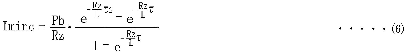
- In the control apparatus according to the first aspect of the invention, the feedback control is executed with a feedback control system having parameters that are determined in accordance with the ILQ design method, wherein the gain of the transfer function, which represents the ratio of the output to the disturbance in the feedback control system, is lower than 0[dB] throughout all frequency ranges. With use of the feedback control system having the parameters determined in accordance with the ILQ design method, it is possible to reduce the adapting steps of adapting the parameters for each of various levels of the state value such as the power supply voltage, which is the responsiveness factor. Further, in the execution of the feedback control with the feedback control system, the driving current is controlled such that the driving current is converged to a control target value (corresponding to a control command value) at a high responsiveness with respect to step change of the control target value and step change of a battery voltage of the drive circuit of the linear solenoid, without causing the control system to be vibrated and without causing coupled vibration in the linear solenoid.
- In the control apparatus according to the second aspect of the invention, the linear solenoid is provided in the linear solenoid valve, wherein the linear solenoid valve is configured to output the signal pressure whose magnitude corresponds to the driving current that is determined through the feedback control. Owing to this arrangement, the driving current of the linear solenoid is converged to the control target value at a high responsiveness without the driving current being fluctuated, whereby the signal pressure outputted from the linear solenoid valve can be controlled to provide a high responsiveness without its fluctuation.
- In the control apparatus according to the third aspect of the invention, in the hydraulic control unit of the vehicle automatic transmission, the linear solenoid valve is configured to supply the signal pressure to the line-pressure regulator valve for controlling the line pressure generated by the line-pressure regulator valve. Owing to this arrangement, the signal pressure, which is for controlling the line pressure generated by the line-pressure regulator valve provided in the vehicle automatic transmission, can be controlled to provide a high responsiveness without its fluctuation, whereby the line pressure generated by the line-pressure regulator valve can be also controlled to provide a high responsiveness without its fluctuation.
- In the control apparatus according to the fourth aspect of the invention, in the hydraulic control unit of the vehicle automatic transmission, the linear solenoid valve is configured to supply the signal pressure to the hydraulic friction engagement devices for controlling the hydraulic friction engagement devices that are operated to establish the gear positions in the vehicle automatic transmission. Owing to this arrangement, the signal pressure, which is for controlling the hydraulic friction engagement devices provided in the vehicle automatic transmission, can be controlled to provide a high responsiveness without its fluctuation, whereby engaging and releasing actions of each of the hydraulic friction engagement devices can be also controlled to provide a high responsiveness without its vibration.
- In the control apparatus according to the fifth aspect of the invention, the linear solenoid is provided in the actuator, wherein, in the hydraulic control unit for controlling the variable valve-timing mechanism configured to adjust the opening/closing timing of the valves of the vehicle engine, the actuator is configured to supply, to the variable valve-timing mechanism, the signal pressure whose magnitude corresponds to the driving current that is determined through the feedback control, for generating the hydraulic pressure for adjusting the opening/closing timing. Owing to this arrangement, the signal pressure, which is supplied to the variable valve-timing mechanism configured to adjust the opening/closing timing of the valves of the vehicle engine, can be controlled to provide a high responsiveness without its fluctuation, whereby the adjustment of the opening/closing timing by the variable valve-timing mechanism can be also controlled to provide a high responsiveness without its vibration.
- In the control apparatus according to the sixth aspect of the invention, the driving current supplied to the linear solenoid is controlled by the input voltage that is obtained by causing the battery voltage to be subjected to an ON-OFF control based on the PWM signal, wherein the electric circuit of the linear solenoid, through which the driving current flows, is approximated by the series circuit of the resistance and the inductance, wherein the circuit equation related to the instantaneous value of the driving current flowing through the series circuit is formulated, wherein the equation related to the controlled variable for controlling the driving current is formulated, wherein the equation related to the controlled variable is derived as the recurrence equation, wherein the recurrence equation is solved, and the solved recurrence equation is linearized by the approximation equation, and wherein the transfer function of the feedback control is derived from the linearized equation related to the controlled variable, and the derived transfer function is used to determine the controlled variable. Thus, the transfer function, which is accurately linearized and approximated, is derived whereby the controlled variable is determined by calculations, so that it is possible to reduce the adapting steps of adapting the parameters for each of various levels of the state value such as the power supply voltage, which is the responsiveness factor.
- In the control apparatus according to the seventh aspect of the invention, the circuit equation is formulated as the equation (1), the equation related to the controlled variable that is the average value of the driving current in an n-th period (n: natural number) is formulated as the equation (2), the recurrence equation is formulated as the equation (3), and the approximation equation is formulated as the equation (4), where "t[s]" represents the time, "τ[s]" represents each driving period of the PWM signal, "τ1[s]" represents the ON time that is a length of time for which the driving current (i(t)) is supplied to the linear solenoid in each driving period, "Pb[V]" represents the battery voltage, and "L(H)" represents the inductance. Thus, the transfer function, which is accurately linearized and approximated, is derived by the equations (3), (4) whereby the controlled variable is determined by calculations, so that it is possible to reduce the adapting steps.
- In the control apparatus according to the eighth aspect of the invention, the driving current supplied to the linear solenoid is controlled by the input voltage that is obtained by causing the battery voltage to be subjected to an ON-OFF control based on the PWM signal, wherein the resistance Rz[Ω] of the electric circuit of the linear solenoid, through which the driving current flows, is calculated in accordance with equation (5), and the inductance L[H] of the electric circuit is calculated in accordance with equation (6), where "τ[s]" represents each driving period of the PWM signal, "τ1[s]" represents the ON time that is a length of time for which the driving current is supplied to the linear solenoid in each driving period, "τ2[s]" represents an OFF time that is a length of time for which the driving current is not supplied to the linear solenoid in each driving period, "Pb[V]" represents the battery voltage, "Iavec[A]" represents the average value of the driving current in the converged state, and "Iminc[A]" represents the minimum instantaneous current value of the driving current in the converged state, and wherein the parameters are corrected depending on the resistance Rz[Ω] and the inductance L[H] that are calculated in accordance with the respective equations (5) and (6). Thus, actual values of the resistance Rz and the inductance L even after aging for years after production of the vehicle or even under unusual condition such as low or high temperature can be calculated by the equations (5) and (6). Thus, the parameters of the feedback control system are corrected depending on the actual values of the resistance Rz and the inductance L that are calculated as described above, so that it is possible to reduce deterioration of dynamic control characteristics in control of the linear solenoid.
-
-
FIG. 1 is a view schematically showing a construction of a vehicle drive-force transmitting apparatus including an electronic control unit to which the present invention is applied; -
FIG. 2 is a table explaining a combination of each of gear positions of an automatic transmission shown inFIG. 1 and a corresponding one or ones of hydraulic friction engagement devices of the automatic transmission, which are to be engaged to establish the each of the gear positions in the automatic transmission; -
FIG. 3 a block diagram schematically showing a main construction of a hydraulic control unit configured to control the automatic transmission shown inFIG. 1 ; -
FIG. 4 is a hydraulic circuit diagram showing a line-pressure generating device shown inFIG. 3 ; -
FIG. 5 is a functional block diagram showing, by way of examples, an equivalent circuit of a linear solenoid SSLT shown inFIG. 4 , a drive circuit DRV of the linear solenoid SSLT and the electronic control unit for the linear solenoid SSLT, wherein the electronic control unit is designed in accordance with an ILQ design method according to an embodiment of the invention; -
FIG. 6 is a functional block diagram showing, by way of other examples, an equivalent circuit of the linear solenoid SSLT shown inFIG. 4 , a drive circuit DRV of the linear solenoid SSLT and the electronic control unit for the linear solenoid SSLT, wherein the electronic control unit is designed in accordance with the ILQ design method according to the embodiment of the invention; -
FIGS. 7A and 7B are views explaining change of an instantaneous value of a driving current where a drive transistor shown inFIG. 6 is subjected to an ON-OFF control with supply of PWM signal, and also change of an average of the instantaneous value of the driving current in each driving period; -
FIG. 8 is a functional block diagram showing a design process of the feedback control system in the electronic control unit shown inFIG. 6 ; -
FIG. 9 is a flow chart showing the design process of the feedback control system in the electronic control unit shown inFIG. 6 and also determination of a controlled variable in the designed feedback control system; -
FIG. 10 is a result of simulation in which a duty ratio is changed from 0% to 50% at a point 0[s] of time, and shows time response as the result of the simulation, -
FIG. 11 is a view showing a relationship between an output y1 and ON time τ1 and a relationship between an output y2 and the ON time τ1, wherein the output y1 has a linear relationship with respect to possible values of the ON time τ1 while the output y2 has a non-linear relationship with respect to the possible values of the ON time τ1; -
FIG. 12 is a result of simulation in which the duty ratio is set to 5%, and shows the step response as the result of the simulation in case of the non-linear model equation and also in case of the linear model equation; -
FIG. 13 is a result of simulation in which the duty ratio is set to 10%, and shows the step response as the result of the simulation in case of the non-linear model equation and also in case of the linear model equation; -
FIG. 14 is a result of simulation in which the duty ratio is set to 20%, and shows the step response as the result of the simulation in case of the non-linear model equation and also in case of the linear model equation; -
FIG. 15 is a result of simulation in which the duty ratio is set to 30%, and shows the step response as the result of the simulation in case of the non-linear model equation and also in case of the linear model equation; -
FIG. 16 is a result of simulation in which the duty ratio is set to 50%, and shows the step response as the result of the simulation in case of the non-linear model equation and also in case of the linear model equation; -
FIG. 17 is a result of simulation in which the duty ratio is set to 50%, and shows the step response as the result of the simulation in case of a continuous model equation and also in case of a discrete model equation; -
FIGS. 18A and 18B show Bode diagram of a transfer function of a continuous model equation; -
FIG. 19 is a functional block diagram showing a process of determining parameters of the feedback control system in accordance with the ILQ design method in the electronic control unit shown inFIG. 6 ; -
FIG. 20 is a flow chart showing a process of determining the parameters of the feedback control system in accordance with the ILQ design method in the electronic control unit shown inFIG. 6 ; -
FIG. 21 is a flow chart showing a process of determining the controlled variable in the feedback control system in the electronic control unit; -
FIG. 22 is a functional block diagram showing the equivalent circuit of the linear solenoid and the drive circuit of the linear solenoid, which are shown inFIG. 4 and also an electronic control unit of the linear solenoid designed by a two-degree-of-freedom control system according to a comparative example; -
FIGS. 23A and 23B show Bode diagram of the transfer function representing a ratio of an output y to a disturbance d in a feedback controller portion shown inFIG. 22 , and a result of a simulation in which a parameter Tc is changed; -
FIGS. 24A and 24B show Bode diagram of the transfer function representing a ratio of the output y to a manipulated variable u in the feedback controller portion shown inFIG. 22 , and a result of a simulation in which the parameter Tc is changed; -
FIGS. 25A and 25B show Bode diagram of the transfer function Gyd(s) in the feedback controller portion shown inFIG. 6 and a simulation result; -
FIG. 26 shows a simulation result regarding a static current accuracy (absolute error and relative error) in the feedback controller portion shown inFIG. 6 ; -
FIGS. 27A and 27B show Bode diagram of the transfer function G(s) in the feedback controller portion shown inFIG. 6 and a simulation result; -
FIG. 28 is a view explaining a deviation and a feedback correction amount in step response in the feedback controller portion shown inFIG. 6 ; -
FIGS. 29A and 29B show a simulation result of a response to a step change (reduction) of the battery voltage in the feedback controller portion shown inFIG. 6 ; -
FIGS. 30A and 30B show a simulation result of a response to a step change (increase) of the battery voltage in the feedback controller portion shown inFIG. 6 ; -
FIG. 31 is a functional block diagram showing the equivalent circuit of the linear solenoid and the drive circuit of the linear solenoid, which are shown inFIG. 4 , and an electronic control unit for a linear solenoid, which is designed in accordance with the ILQ design method and is constructed according to an embodiment of the invention, for controlling parameter correction; -
FIG. 32 is a view showing a relationship between an inductance of the electric circuit through which the driving current flows, and a minimum instantaneous current value; -
FIG. 33 is a flow chart showing a process for control of correction of the parameters in the electronic control unit shown inFIG. 31 ; and -
FIGS. 34-36 are views showing constructions of main portions of a variable valve-timing apparatus including an electronic control unit constructed according to another embodiment of the invention. - In the present specification, there are descriptions related to various matrixes, wherein a suffix "-1" on right upper side of a matrix means an inverse matrix that is inverse to the matrix, a suffix "T" on right upper side of a matrix means a transposed matrix that is transposed to the matrix, and a matrix I means an identity matrix.
- Hereinafter, some preferred embodiments of the invention will be described in detail with reference to the accompanying drawings.
-
FIG. 1 is a view schematically showing a construction of a vehicle drive-force transmitting apparatus 20 which is to be provided in a vehicle and which includes anelectronic control unit 170 according to an embodiment of the invention.FIG. 1 shows also a construction of a hydraulic variable valve-timing apparatus 200 including anelectronic control unit 270 according to another embodiment of the invention. The drive-force transmitting apparatus 20 includes atorque converter 12 connected to avehicle engine 10, a vehicleautomatic transmission 14, adifferential gear device 16 and ahydraulic control unit 18 configured to control shifting actions of theautomatic transmission 14, in addition to theelectronic control unit 170 configured to control thehydraulic control unit 18. A drive force outputted from theengine 10 is transmitted to drive wheels (not shown) of the vehicle via, for example, thetorque converter 12, theautomatic transmission 14, thedifferential gear device 16 and right and leftaxles 22. - The
torque converter 12 includes apump impeller 28 connected to a crankshaft 26 of theengine 10, aturbine impeller 32 which is connected to aninput shaft 30 of theautomatic transmission 14 and to which the drive force is transmitted via a fluid under pressure, astator impeller 38 connected through a one-way clutch 34 to ahousing 36 as a non-rotary member, and a lock-up clutch 40 configured to directly connect thepump impeller 28 and theturbine impeller 32 through a damper (not shown). - The
automatic transmission 14 is a multi-speed transmission configured to establish four forward gear positions and one reverse gear position. Theautomatic transmission 14 includes, in addition to theinput shaft 30, aplanetary gear unit 44 of Ravignawx type, aring gear 48 that is to be rotated together with aring gear 46 of theplanetary gear unit 44, and acounter shaft 50 serving as an output shaft configured to transmit the drive force between thering gear 48 and thedifferential gear device 16. - The
planetary gear unit 44 consists of aplanetary gear device 52 of single pinion type and aplanetary gear device 54 of double pinion type, wherein acarrier 56 and thering gear 46 are rotary elements common to theplanetary gear devices planetary gear device 52 includes rotary elements in the form of asun gear 58,planetary gears 60 attached to thecarrier 56, and thering gear 46. Theplanetary gear device 54 includes rotary elements in the form of asun gear 62 and first andsecond pinions 64 66, such that the first andsecond pinions carrier 56. - Some of the rotary elements of the
planetary gear devices housing 36 through three brakes B1, B2, B3, and some of the rotary elements are engaged to thehousing 36 through two one-way clutches FC1, FC2 depending on their rotation directions. It is noted that the vehicle drive-force transmitting apparatus 20 is constructed substantially symmetrically about the axis CL1 (corresponding to an axis of the input shaft 30), except thetorque converter 12 and thecounter shaft 50 of theautomatic transmission 14, so that a lower side of the axis CL1 is not shown inFIG. 1 . - Each of the clutches C1, C2, C3 and the brakes B1, B2, B3 as the hydraulic friction engagement devices is constituted by, for example, a multiple-disc clutch or a band brake including one band or two bands that wound in respective opposite directions. Each of the clutches C1, C2, C3 and the brakes B1, B2, B3 is controlled by the
hydraulic control unit 18 that is operated in accordance with commands supplied from theelectronic control unit 170, so as to be placed in its engaged state, slipping state or released state, whereby theautomatic transmission 14 can establish four forward gear positions and one rear gear position that are different in a gear ratio γ (= rotational speed ofinput shaft 30 / rotational speed of counter shaft 50), as shown inFIG. 2 in which "1ST", "2ND", "3RD", "4TH" represent the respective four forward gears positions, i.e., first, second, third and fourth gear positions, respectively. The gear ratio γ decreases in a direction from the first gear position toward the four gear position. Further, inFIG. 2 , "P", "R", "N", "D", "2", "L" represent a parking range, a reverse range, a neutral range, a drive range, a second range and a low range, respectively, which are selectively selected by a manual operation of theshift lever 84. Each of the parking range and the neutral range is a non-driving range that is to be selected when the vehicle is not driven to run. The reverse range is a driving range that is to be selected when the vehicle is driven to run in reverse direction. Each of the drive range, the second range and the low range is a driving range that is to be selected when the vehicle is driven to run in forward direction. -
FIG. 2 is a table explaining a combination of each of gear positions of theautomatic transmission 14 shown inFIG. 1 and a corresponding one or ones of the hydraulic friction engagement devices of theautomatic transmission 14, which are to be engaged to establish the each of the gear positions in theautomatic transmission 14. In the table ofFIG. 2 , "O" indicates an operated or engaged state of the engagement devices, and blank indicates a non-operated or released state of the engagement devices. For example, a shift-up action from the second gear position to the third gear position in the drive range is executed by causing the clutch C2 to be placed in the engaged state and maintaining the engaged state of the clutch C1. Further, a shift-down action from the fourth gear position to the third gear position is executed by causing the clutch C1 to be placed in the engaged state and causing the brake B1 to be placed in the released state, such that the engaging action of the clutch C1 and the releasing action of the brake B1 are executed by a so-called "clutch-to-clutch shifting", namely, executed in an overlap state or an underlap state. - The
hydraulic control unit 18 incudes first and second electromagnetic opening/closing valves SV1, SV2 that are to be controlled to establish the gear positions in theautomatic transmission 14, two linear solenoid valves SLT, SLU and anoil temperature sensor 88. The linear solenoid valve SLT is configured to generate a control hydraulic pressure PS[MPa] whose magnitude corresponds to an engine load, i.e., a throttle opening degree TA[%] detected by a throttle opening-degree sensor 76. The linear solenoid valve SLU is configured to generate a hydraulic pressure for controlling, for example, an operation state of the lock-up clutch 40, namely, for establishing a frictional engagement of the clutch 40, releasing the frictional engagement and controlling a slipping amount of the clutch 40. Theoil temperature sensor 88 serves as a working-fluid temperature detecting device configured to detect a working-fluid temperature Thoil[°C] in thehydraulic control unit 18. It is noted that the control hydraulic pressure PS corresponds to "signal pressure" recited in the appended claims. - The electronic control unit (ECU) 170 includes a so-called microcomputer incorporating a CPU, a ROM, a RAM and an input-output interface (not shown). The
electronic control unit 170 is configured to control the hydraulic friction engagement devices (such as the clutches C1, C2, C3 and the brakes B1, B2, B3) and the lock-up clutch 40 that are included in the drive-force transmitting apparatus 20, by causing the CPU to process various input signals, according to control programs stored in the ROM, while utilizing a temporary data-storage function of the RAM. Theelectronic control unit 170 corresponds to "control apparatus" recited in the appended claims. - The
electronic control unit 170 receives various input signals from various sensors provided in the vehicle, such as: an output signal of the above-described throttle opening-degree sensor 76 configured to detect the throttle opening degree TA in an intake pipe (not shown) of theengine 10; an output signal of anengine speed sensor 78 configured to detect an engine rotational speed Ne[rpm]; an output signal of an input-shaft speed sensor 80 configured to detect an input-shaft rotational speed Nin[rpm]; an output signal of arunning speed sensor 82 configured to detect a counter-shaft rotational speed Nc[rpm], i.e., a vehicle running speed Vc[km/h]; an output signal of ashift position sensor 86 configured to detect an operation position Pst of the above-describedshift lever 84, namely, detect in which one of the parking range, the reverse range, the neutral range, the drive range, the second speed range and the low speed range theshift lever 84 is placed; an output signal of the above-describedoil temperature sensor 88 configured to detect the temperature Thoil of a working fluid (working oil) in thehydraulic control unit 18. -
FIG. 3 a block diagram schematically showing a main construction of thehydraulic control unit 18 configured to control theautomatic transmission 14 shown inFIG. 1 . Ahydraulic pump 90 is to be driven or operated by theengine 10 so as to suck the working fluid returned trough astrainer 92 and to supply the working fluid to a line-pressure generating device 100. The line-pressure generating device 100 regulates the working fluid supplied from thehydraulic pump 90, to a line pressure PL[MPa] that corresponds to the engine load, and then outputs the regulated line pressure PL as an original pressure of each of the hydraulic friction engagement devices in the form of the clutches C1, C2, C3 and the brakes B1, B2, B3, to ashift valve device 102. Amanual valve 104 is mechanically connected to theshift lever 104, and selects a destination to which the line pressure PL is to be supplied, such that the selected destination is dependent on the operation position Pst of theshift lever 84. By the selection, the hydraulic pressure corresponding to the operation position Pst of theshift lever 84, e.g., a reverse-range pressure, a drive-range pressure, a second-range pressure or a low-range pressure is outputted to theshift valve device 102. Each of the first electromagnetic opening/closing valve SV1 and the second electromagnetic opening/closing valve SV2 outputs an output pressure that is controlled by theelectronic control unit 170 to select one of the gear positions, and the output pressure is supplied to theshift valve device 102. - The
shift valve device 102 includes a 1-2 shift valve, a 2-3 shift valve and a 3-4 shift valve (not sown) that are to be switched for a shifting action, based on the hydraulic pressure corresponding to the operation position Pst of theshift lever 84 and supplied from themanual valve 104 and also the output pressure supplied from each of the first and second electromagnetic opening/closing valve SV1, SV2. Theshift valve device 102 supplies an engaging pressure to each of a corresponding one or ones of the hydraulic friction engagement devices in the form of the clutches C1, C2, C3 and the brakes B1, B2, B3, in accordance with the corresponding combination indicated inFIG. 2 . The clutches C1, C2, C3 and the brakes B1, B2 are connected to a C1 accumulator AC1, a C2 accumulator AC2, a C3 accumulator AC3, a B1 accumulator AB1 and a B2 accumulator AB2, respectively, such that an increase of the supplied engaging pressure, i.e., an engaging torque in each of these hydraulic friction engagement devices is alleviated. -
FIG. 4 is a hydraulic circuit diagram showing the line-pressure generating device 100 shown inFIG. 3 . A line-pressure regulator valve 110 includes: aplunger 112; aspool valve body 114 which is in contact with theplunger 112 and which is axially movable so as to selectively allow and inhibit communication between aninput port 110b and anoutput port 110d; and aspring 118 that constantly forces or biases thespool valve body 114 through aspring receiver plate 116 in a connection inhibiting direction that causes thespool valve body 114 to inhibit the communication between theinput port 110b and theoutput port 110d. The line-pressure regulator valve 110 regulates the working fluid supplied from thehydraulic pump 90 through theinput port 110b, based on the control hydraulic pressure PS supplied from the linear solenoid valve SLT through aninput port 110a, such that the working fluid is regulated to the line pressure PL that corresponds to a load of theengine 10. Through aninput port 110c, the hydraulic pressure, which is supplied through theinput port 110b, is supplied as a feedback hydraulic pressure. The line pressure PL is expressed by equation (7) given below, wherein "WREG[N]" represents a biasing force of thespring 118, "AREG1[mm2]" represents a annular-shaped pressure-receiving area of aland 120 of thespool valve body 114, and "AREG2[mm2]" represents a pressure receiving area of theplunger 112 on which the hydraulic pressure forcing thespool valve body 114 in the above-described connection inhibiting direction acts. The equation (7) indicates that the line pressure PL is generated in proportion with the control hydraulic pressure PS. Thus, since the magnitude of the control hydraulic pressure PS is made correspond to the engine load, the line pressure PL is regulated to have a magnitude corresponding to the engine load.
- The linear solenoid valve SLT includes: a
spool valve body 132 configured to selectively allow and inhibit communication between aninput port 130a and anoutput port 130b; and aspring 134 that constantly forces or biases thespool valve body 132 in a connection allowing direction that causes thespool valve body 132 to allow the communication between theinput port 130a and theoutput port 130b. To the linear solenoid valve SLT, a constant hydraulic pressure PSOL[MPa] is supplied through theinput port 130a, and the supplied constant hydraulic pressure PSOL is regulated to the control hydraulic pressure PS corresponding to a driving current i(t)[A] of the linear solenoid SSLT which is controlled by theelectronic control unit 170, so that the regulated control hydraulic pressure PS is outputted through theoutput port 130b. The control hydraulic pressure PS (or a change characteristic with respect to a thrust FI) is expressed by equation (8) given below, wherein "FI[N]" represents a thrust, as a driving signal SD1 corresponding to the driving current i(t) of the linear solenoid SSLT, which forces thespool valve body 132 in a connection inhibiting direction that causes thespool valve body 132 to inhibit the communication between theinput port 130a and theoutput port 130b, "WSLT[N]" represents a biasing force of thespring 134, and "ASLT[mm2]" represents an annular-shaped pressure-receiving area of aland 136 of thespool valve body 132. Afeedback fluid chamber 140 defined between theland 136 and aland 138 is in communication with theoutput port 130b via afluid passage 142, so that a hydraulic pressure acting on the annular-shaped pressure-receiving area of theland 136 corresponds to the control hydraulic pressure PS. The thrust FI has a magnitude that is proportional with the driving current i(t) of the linear solenoid SSLT.
- A
pressure reducing valve 150 includes aspool valve body 152 configured to selectively allow and inhibit communication between aninput port 150a and anoutput port 150b; and aspring 154 that constantly forces or biases thespool valve body 152 in a connection allowing direction that causes thespool valve body 152 to allow the communication between theinput port 150a and theoutput port 150b. Thepressure reducing valve 150 regulates the line pressure PL supplied thereto through theinput port 150a, to the constant hydraulic pressure PSOL, and outputs the constant hydraulic pressure PSOL through theoutput port 150b. The constant hydraulic pressure PSOL outputted through theoutput port 150b is supplied to the linear solenoid valve SLT and the linear solenoid valve SLU. To aninput port 150c of thepressure reducing valve 150, the hydraulic pressure outputted through theoutput port 150b is supplied as the feedback hydraulic pressure. The constant hydraulic pressure PSOL is expressed by equation (9) given below, wherein "AMOD[mm2]" represents an area of a pressure-receiving portion of thespool valve body 152, which is in communication with theinput port 150c, and "WMOD[N]" represents a biasing force of thespring 154.
-
FIG. 5 is a functional block diagram showing an equivalent circuit of the linear solenoid SSLT shown inFIG. 4 , a drive circuit DRV of the linear solenoid SSLT and theelectronic control unit 170a for the linear solenoid SSLT, which is constructed according to an arrangement of the embodiment of the invention. InFIG. 5 , a portion of afeedback controller portion 176a, which is to be subjected to a control, is surrounded by one-dot chain line, and the portion subjected to the control has a construction without a feedthrough term.FIG. 6 is a functional block diagram showing the equivalent circuit of the linear solenoid SSLT shown inFIG. 4 , the drive circuit DRV of the linear solenoid SSLT and theelectronic control unit 170b for the linear solenoid SSLT, which is constructed according to another arrangement of the embodiment of the invention. InFIG. 6 , a portion of afeedback controller portion 176b, which is to be subjected to a control, is surrounded by one-dot chain line, and the portion subjected to the control has a construction with a feedthrough term. The functional block diagrams shown inFIGS. 5 and6 are identical with each other except thefeedback controller portion 176a shown inFIG. 5 and thefeedback controller portion 176b shown inFIG. 6 that are different from each other. It is noted that theelectronic control unit 170a and theelectronic control unit 170b are examples of theelectronic control unit 170, and the feedback control system of theelectronic control unit 170 is designed in accordance with ILQ design method. The term "feedback control system" is interpreted to mean a construction configured to execute an automatic control by a feedback control, and is represented by, for example, a control block diagram shown in thefeedback controller portion 176a inFIG. 5 and a control block diagram shown in thefeedback controller portion 176b inFIG. 6 . - There will be described functions of the
electronic control unit 170, with reference toFIG. 6 that shows theelectronic control unit 170b. The linear solenoid SSLT has electrical characteristics that are represented by a RL series circuit of an equivalent inductance Ls[H] and an equivalent resistance Rs[Ω]. It is noted that an ON resistance of a drive transistor Tr (described below) is included in the equivalent resistance Rs. The drive circuit DRV for the linear solenoid SSLT includes: a terminal Bt through which a battery voltage Pb[V] is supplied as a power supply voltage; a drive transistor Tr; a detection resistance Rd[Ω]; an operational amplifier AMP and an A/D converter ADC. With the drive transistor Tr being ON, the driving current i(t) is caused to flow through the linear solenoid SSLT by the battery voltage Pb. The detection resistance Rd[Ω] is connected in series with the linear solenoid SSLT, so that the driving current i(t) flowing through the linear solenoid SSLT is taken as a voltage difference between opposite ends of the detection resistance Rd. The taken voltage difference is amplified by the operational amplifier AMP, and is then converted into a digitized signal in the form of a current signal Iact representing the actual driving current i(t). The current signal Iact is inputted to theelectronic control unit 170b. - The
electronic control unit 170b includes, in addition to thefeedback controller portion 176b, a command-value setting portion 172, aparameter storing portion 174 and aPWM portion 178. - The command-
value setting portion 172 sets a current command value r(t) representing a control target value in the form of an average value of the driving current i(t) of the linear solenoid SSLT, in accordance with a predetermined running map, based on the signal indicative of the throttle opening degree TA, the signal indicative of the engine rotational speed Ne, the signal indicative of the input-shaft rotational speed Nin, the signal indicative of the counter-shaft rotational speed Nc, i.e., the vehicle running speed Vc and the signal indicative of the operation position Pst of theshift lever 84. The command-value setting portion 172 outputs the current command value r(t) that is supplied to thefeedback controller portion 176b. - Parameters, which are applied to the feedback control system as described below, are stored in the
parameter storing portion 174 in a stage of production of theparameter storing portion 174. - The
feedback controller portion 176b causes the current command value r(t) supplied from the command-value setting portion 172, to be subjected to the feedback control using the current signal Iact representing the actual driving current i(t), and outputs, as an output y, the current command value r(t) subjected to the feedback control. The output y is outputted to thePWM portion 178. The output y is a signal representing a duty ratio dependent on an average driving current i(nτ) as a controlled variable that is described below. - The
PWM portion 178 generates a PWM (pulse width modulation) signal based on the output y supplied from thefeedback controller portion 176b. ThePWM portion 178 outputs the generated PWM signal to a gate electrode of the drive transistor Tr, and executes the ON-OFF control of the drive transistor Tr. An input voltage vin(t)[V] inputted to the linear solenoid SSLT through a side of the drive transistor Tr is controlled by the duty ratio of the ON-OFF control of the drive transistor Tr, whereby the driving current i (t) of the linear solenoid SLT is controlled. - Regarding specification values of various elements in the present embodiment, for example, characteristic values of the resistances and inductance are represented by the equivalent resistance Rs = 5.3[Ω], the detection resistance Rd = 0.5[Ω] and the equivalent inductance Ls = 20 * 10-3[H] in nominal values. The nominal value is an average value of each of the characteristic values of the resistances and inductance. The actual characteristic value (hereinafter referred to as an actual value) varies depending on production variation and temperature change. Further, the battery voltage Pb is 15[V], and a drive frequency fd of the PWM signal is 1/3.324 * 103[Hz]. Therefore, each driving period τ is 1/3 * 10-2[s] (= 1/fd).
-
FIGS. 7A and 7B are views explaining change of an instantaneous value of the driving current i(t) where the drive transistor Tr shown inFIG. 6 is subjected to the ON-OFF control with supply of the PWM signal, and also change of an average lave of the instantaneous value of the driving current i(t) in each driving period τ.FIGS. 7A and 7B show a case in which the PWM signal whose duty ratio is 50% starts to be inputted to the drive transistor Tr at a point 0[s] of time. The drive transistor Tr is ON in a fist half (50%) of each driving period τ, and is OFF in a second half (50%) of each driving period τ.FIG. 7A shows change of the input voltage vin(t) with respect to time, whileFIG. 7B shows change of the driving current i(t) with respect to time. As shown inFIG. 7A , the input of 15[V] and the input of 0[V] are alternately made to the linear solenoid SSLT as the input voltage vin(t) in every half (about 1.67[ms]) of each driving period τ. InFIG. 7B , one of two broken lines is a line that connects minimum instantaneous current values Imin appearing in the respective driving periods τ, and the other of the two boken lines is a line that connects maximum instantaneous current values Imax appearing in the respective driving periods τ. As shown inFIG. 7B , the instantaneous value of the driving current i(t), which flows through the linear solenoid SSLT, is fluctuated between the minimum instantaneous current value Imin and the maximum instantaneous current value Imax in each driving period τ, and is gradually increased with each of the minimum instantaneous current value Imin and the maximum instantaneous current value Imax being converged to a constant value after a certain length of time elapses. The average lave of the instantaneous value of the driving current i(t) is also gradually increased with the increases of each of the minimum instantaneous current value Imin and the maximum instantaneous current value Imax, and is converged to a constant value after a certain length of time elapses. The average Iavec is an average of the instantaneous value of the driving current i(t) in the converged state. The minimum instantaneous current values Imin is a minimum of the instantaneous value of the driving current i(t) in the converged state. It is noted that the "converged state" is interpreted to mean a state in which the minimum instantaneous current value Imin and the average lave of the instantaneous value of the driving current i(t) become constant or substantially constat without change or substantial change. -
FIG. 8 is a functional block diagram showing adesign process 190 of the feedback control system in the electronic control unit shown 170b shown inFIG. 6 . As shown inFIG. 8 , thedesign process 190 includes steps of "electric circuit approximation 190a", "first formulation 190b", "second formulation 190c", "recurrence equation derivation 190d", "recurrence equation solution 190e", "linearization byapproximation equation 190f', "transfer function derivation byILQ design method 190g" and "parameter input 190h". Each of these steps may be implemented by either a human operator or an electronic computer such as AI (Artificial Intelligence). Where the steps are implemented by the electronic computer, the electronic computer constitutes portions configured to implement the respective steps. It is noted that the electronic control unit shown 170b may be interpreted to include an electriccircuit approximating portion 190a, afirst formulating portion 190b, asecond formulating portion 190c, a recurrence-equation deriving portion 190d, a recurrence-equation solving portion 190e, a linearizingportion 190f, a transfer-function deriving portion 190g and aparameter inputting portion 190h, which are configured to implement the respective steps. - The step of the "
electric circuit approximation 190a", which is implemented first, is a step of approximating a series circuit including a resistance Rz[Ω] and an inductance L[H], to the electric circuit of the linear solenoid SSLT through which the driving current i(t) flows, wherein the resistance Rz is a sum of the equivalent resistance Rs of the linear solenoid SSLT and the detection resistance Rd, and the inductance L is synonymous with the equivalent inductance Ls of the linear solenoid SSLT. The step of the "first formulation 190b", which is implemented next, is a step of formulating a circuit equation related to the instantaneous value of the driving current i(t) that flows in the approximated series circuit. The step of the "second formulation 190c", which is implemented next, is a step of formulating an equation related to the controlled variable in control of the driving current i(t). The step of the "recurrence equation derivation 190d", which is implemented next, is a step of deriving a recurrence equation from the equation related to the controlled variable. The step of the "recurrence equation solution 190e", which is implemented next, is a step of obtaining a solution of the recurrence equation, by solving the recurrence equation. The step of "linearization byapproximation equation 190f', which is implemented next, is a step of linearizing the solved recurrence equation by an approximation equation. The step of "transfer function derivation byILQ design method 190g ", which is implemented next, is a step of deriving a transfer function by using the recurrence equation that has been linearized and solved. The "parameter input 190h", which is implemented next, is a step of writing or inputting parameters, which are to be applied to the derived transfer function, into theparameter storing portion 174 of theelectronic control unit 170. Specific contents of these steps will be described below. -
FIG. 9 is a flow chart showing the design process of the feedback control system in theelectronic control unit 170b shown inFIG. 6 . Among steps of the design process, each of the steps except step S70 is started to be implemented and is implemented once in a stage of design process. Step S70 is implemented once when the parameters are stored into theelectronic control unit 170b provided in the drive-force transmitting apparatus 20 of each of vehicles. - At step S10 corresponding to the step of the "
electric circuit approximation 190a", the electric circuit of the linear solenoid SSLT, through which the driving current i(t) flows, is approximated by the series circuit of the resistance Rz and the inductance Ls. Step S10 is followed by step S20. - At step S20 corresponding to the step of the "
first formulation 190b", equation (10) in the form of a differential equation is formulated as the circuit equation related to the electric circuit which is constituted by the linear solenoid SSLT and the drive circuit DRV and though which the driving current i(t) flows, wherein the input voltage inputted to the linear solenoid SSLT through the side of the drive transistor Tr is represented by "vin(t)". It is noted that equation (10) is identical with the above-described equation (1). Step S20 is followed by step S30. - At step S30 corresponding to the step of the "
second formulation 190c", equation (11) is formulated as the equation related to the controlled variable, which is constituted by an average driving current i(nτ) that is the average of the instantaneous value of the driving current i(t) in the n-th period (n: natural number), when the driving current i(t) is to be controlled. It is noted that the equation (11) is identical with the above-described equation (2). Step S30 is followed by step S40.
[Formulas 3]

- At step S40 corresponding to the step of the "
recurrence equation derivation 190d", an equation related to the average driving current i(nτ) as the controlled variable is derived as the recurrence equation. Equation (12) is obtained by applying Laplace transform to both sides of the above-described equation (10), and is transformed into equation (13). Further, the transfer function Gp(s), which is of primary delay, is represented by equation (14).
[Formulas 4]


- Equation (15) related to the driving current i(t) is established by obtaining a step response of the driving current i(t) in response to a step input of the input voltage vin(t) at a point 0[s] of time in the above transfer function Gp(s), wherein "Pb" represents the battery voltage as described above.
[Formula 5]
- Equation (16) related to the average driving current i(τ) in the first period is established in accordance with superposition principle, wherein τ1/τ * 100[%] corresponds to the duty ratio. Equation (17) related to the average driving current i(τ) is obtained by transforming the equation (16). It is noted that an ON time τ1[s] represents a length of time for which the drive transistor Tr is controlled to be ON, and an OFF time τ2[s] represents a length of time for which the drive transistor Tr is controlled to be OFF. The OFF time τ2 is obtained by subtracting the ON time τ1 from the driving period τ.
[Formulas 6]

- Similarly, equation (18) related to the average driving current i(2τ) in the second period is established. Since equation (19) is established, equation (20) related to the average driving current i(2τ) is established. Further, by substantially the same equation transform as the derivation of the average driving current i(τ) and average driving current i(2τ), equation (21) in the form of a recurrence equation is derived. It is noted that the equation (21) is identical with the above-described equation (3). Step S40 is followed by step S50.
[Formula 7]
[Formula 8]
[Formulas 9]

- At step S50 corresponding to the step of the "
recurrence equation solution 190e", the recurrence equation is solved so that the solution related to the controlled variable is obtained. - Where the average driving current an and variables α, β are defined as respective equations (22), (23), (24), the above-described equation (21) is rewritten into equation (25). Therefore, the average driving current an is expressed by equation (26) using a calculation related to a sum of geometric series.
[Formulas 10]


- Since the variables α, β are defined by the respective equations (23), (24), equation (27) related to α*β is established. Further, since the average driving current a1 is calculated as the average driving current i(τ) in the above-described equation (17), the above-described equation (26) is rewritten to equation (28). Thus, the solution related to the controlled variable in the form of the average driving current an (= average driving current i(nτ)) is obtained through the equation (28).
[Formula 11]
[Formula 12]
-
FIG. 10 is a result of simulation in which the duty ratio is changed from 0% to 50% at a point 0[s] of time, and shows time response as the result of the simulation, which is in accordance with the equation (28). InFIG. 10 , X marks indicate the time response of the driving current i(t) which is in accordance with the equation (28), and broken line indicates a converged value of the driving current i(t). The converged value after a sufficient length of time has elapsed, namely, the converged driving current a∞ with n→∞ in the equation (28) is represented as in equation (29). Thus, since the variable β defined in the above-described equation (24) is β < 1, equation (30) related to the converged driving current a∞ is established.
[Formulas 13]

- Thus, the converged driving current a∞ after the sufficient length of time has elapsed corresponds to "duty ratio * battery voltage Pb / resistance Rz", as indicated in the above-described equation (30), so that it is understood that the converged driving current a∞ has a linear relationship with respect to the duty ratio. Step S50 is followed by step S60.
- At step S60 corresponding to steps of the "linearization by
approximation equation 190f' and "transfer function derivation byILQ design method 190g", the solved recurrence equation is linearized by the approximation equation, and the transfer function is derived. - In the above-described equation (28), the average driving current an as the controlled variable has a non-linear relationship with respect to the duty ratio. Thus, the recurrence equation is linearized for facilitating designing of the
feedback controller portion 176b. Outputs y1, y2 are defined by equations (31), (32), respectively.FIG. 11 is a view showing a relationship between the output y1 and ON time τ1 and a relationship between the output y2 and the ON time τ1, wherein the output y1 has a linear relationship with respect to possible values of the ON time τ1 while the output y2 has a non-linear relationship with respect to the possible values of the ON time τ1. From the result shown inFIG. 11 , it is possible to regard that the outputs y1, y2 are substantially equal to each other, so that it is possible to regard that a left side of equation (33), which has a non-linear relationship with respect to the ON time τ1 is substantially equal to a right side of the equation (33), which has a linear relationship with respect to the ON time τ1. Thus, by applying the equation (33) to the equation (28), the average driving current an as the controlled variable is represented by equation (34) that is linearized by the approximation equation, so as to have a linear relationship with respect to the duty ratio. That is, the equation (33) is the approximation equation by which the equation (28) related to the controlled variable is linearized. It is noted that the equation (33) is identical with the above-described equation (4).
[Formulas 14]

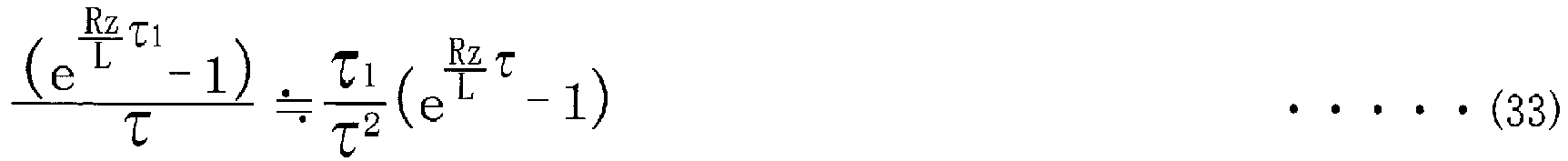
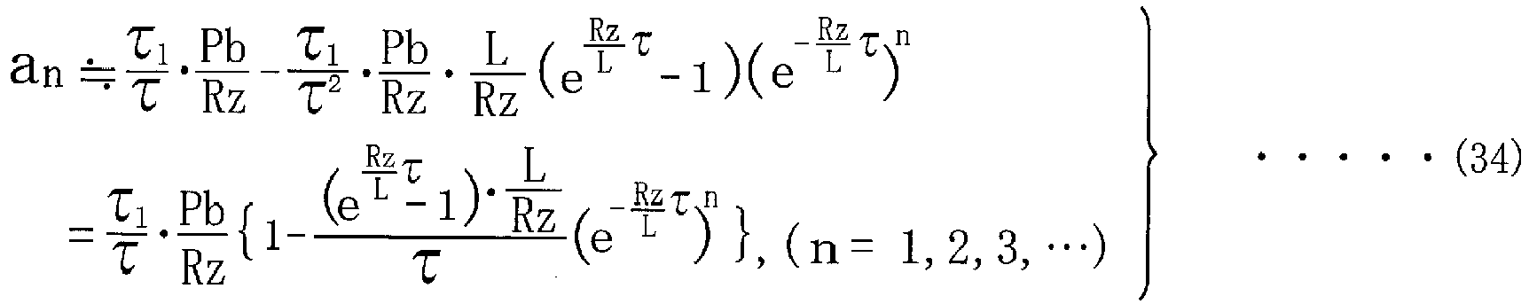
- There will be described influence to the time response of the average driving current an as the controlled variable where the average driving current an is given a linear relationship with respect to the duty ratio as represented by equation (34). The step response of the average driving current an in response to the step input of the input voltage vin(t) at the point 0[s] is shown in
FIGS. 12-16 in which X marks indicate the average driving current an in accordance with the equation (28) that is a non-linear model equation, black circle marks indicate the average driving current an in accordance with the equation (34) that is a linear model equation, and broken line indicates converged value of the average driving current an.FIG. 12 is a result of simulation in which the duty ratio is set to 5%, and shows the step response as the result of the simulation in case of the non-linear model equation and also in case of the linear model equation.FIG. 13 is a result of simulation in which the duty ratio is set to 10%, and shows the step response as the result of the simulation in case of the non-linear model equation and also in case of the linear model equation.FIG. 14 is a result of simulation in which the duty ratio is set to 20%, and shows the step response as the result of the simulation in case of the non-linear model equation and also in case of the linear model equation.FIG. 15 is a result of simulation in which the duty ratio is set to 30%, and shows the step response as the result of the simulation in case of the non-linear model equation and also in case of the linear model equation.FIG. 16 is a result of simulation in which the duty ratio is set to 50%, and shows the step response as the result of the simulation in case of the non-linear model equation and also in case of the linear model equation. As is obvious fromFIGS. 12-16 , the equation (33) as the approximation equation provides a satisfactory approximation also in the step response. - From the equation (34), a transfer function G(s) (continuous time model) of the system is obtained. There will be described a transfer function G1(s) of the system in which a time function of the step response is represented by equation (35). Equation (36) is obtained by applying Laplace transform to both sides of the equation (35). Thus, the transfer function G1(s) is represented by equation (37).
[Formulas 15]


- By comparing coefficients in the equations (34), (35), equations (38), (39), (40) are established. A coefficient "(A-B)T" of "s" constituting a numerator of a right side of the equation (37) corresponds to equation (41), so that the transfer function G(s) is represented by equation (42). The transfer function G(s) is represented by equation (43), which is obtained by applying the above-described specification values into the equation (42).
[Formulas 16]


-
FIG. 17 is a result of simulation in which the duty ratio is set to 50%, and shows the step response as the result of the simulation in case of the equation (42) as a continuous model equation and also in case of the equation (28) as a discrete model equation. InFIG. 17 , solid line indicates the driving current i(t) in accordance with from the continuous model equation, X marks indicate the driving current i(t) in accordance with the discrete model equation, and broken line indicates the converged value of the driving current i(t). The values calculated by the equation (28) as the discrete model equation are the same as those sampled from the step response calculated by the equation (42) as the continuous model equation in the respective driving periods τ. -
FIGS. 18A and 18B show Bode diagram of the transfer function G(s) of the continuous model equation.FIG. 18A shows frequency characteristic of a gain of the transfer function G(s).FIG. 18B shows frequency characteristic of a phase of the transfer function G(s). From a transmission representation of the transfer function G(s) of the equation (42), it is understood that the transfer function G(s) is formed by a parallel combination of a primary delay block and a gain block that has no dynamics. - There will be described a derivation of a state-space representation model.
- The transfer function G(s), which is equation (45), is represented by a state space representation (controllability canonical form) in the form of equations (44). With a steady-state gain of the input and output being taken into consideration, equations (46), (47) using a state variable x1 are established.
[Formulas 17]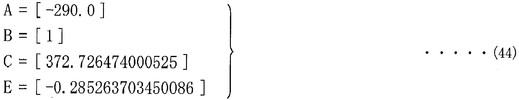


- After the transfer function G(s) has been derived as described above, step S70 is implemented.
- At step S70 corresponding to the step of "
parameter input 190h", the parameters of the feedback control system are written or inputted into theparameter storing portion 174 of theelectronic control unit 170b. The input of the parameters into theparameter storing portion 174 is made in process of production of each vehicle. The process of determining the parameters of the feedback control system will be described below. Thus, the control target value of the driving current i(t) of the linear solenoid SSLT is determined by using the transfer function that can be represented by a mathematical expression. The process shown in the flow chart ofFIG. 9 is completed with the implementation of step S70. -
FIG. 19 is a functional block diagram showing a process of determining the parameters of the feedback control system in accordance with ILQ design method in theelectronic control unit 170b shown inFIG. 6 . AnILQ designing portion 192 is used at the step of "transfer function derivation byILQ design method 190g" shown inFIG. 8 . TheILQ designing portion 192 is a computer aided design system (CAD: Computer Aided Design) as a design tool for executing calculations in the ILQ design method (Inverse Linear Quadratic design method), and includes again determining portion 192a, a regular-matrix determining portion 192b, a positive-definite-matrix determining portion 192c, a parameter storing portion 192d and aparameter inputting portion 192e. The ILQ design method, which is referred also to as an inverse-linear quadratic equation optimal control system design method, is an optimal servo system design method to which a result of an inverse problem of an optimal regulator problem (LQ problem) based on a modern control theory is skillfully applied. In the ILQ design method, the solution of the LQ problem can be derived by a simple pole assignment without weighting. The ILQ design method is disclosed in details in a plurality of documents (e.g., title: Robust Control; authors: Hidenori Kimura, Takao Fujii, Takehiro Mori; published by Korona-sha in 1994; see pages 141-153). - The
gain determining portion 192a determines a gain K in the feedback control system. The determination of the gain K in accordance with the ILQ design method will be described specifically below. After having determined the gain K, thegain determining portion 192a outputs a command signal to the regular-matrix determining portion 192b. It is noted that the gain K corresponds to one of "parameters" recited in the appended claims. - When receiving the command signal supplied from the
gain determining portion 192a, the regular-matrix determining portion 192b determines a regular matrix V in the feedback control system. The determination of the regular matrix V in accordance with the ILQ design method will be specifically described below. After having determined the regular matrix V, the regular-matrix determining portion 192b outputs a command signal to the positive-definite-matrix determining portion 192c. - When receiving the command signal supplied from the regular-
matrix determining portion 192b, the positive-definite-matrix determining portion 192c determines a positive definite matrix ∑ in the feedback control system. The determination of the positive definite matrix ∑ in accordance with the ILQ design method will be de described specifically below. After having determined the positive definite matrix ∑, the positive-definite-matrix determining portion 192c outputs the parameters such as the gain K, regular matrix V and positive definite matrix ∑, to the step of "parameter input 190h" shown inFIG. 8 . It is noted that the positive definite matrix ∑ corresponds to one of "parameters" recited in the appended claims. - As described above, at the step of "
parameter input 190h", the parameters such as the gain K, regular matrix V and positive definite matrix ∑ are written or inputted into theparameter storing portion 174 of theelectronic control unit 170b. - There will be described in detail a process of the determination of the parameters of the feedback control system in accordance with the ILQ design method. In the ILQ design method, when a state feedback gain K is given, necessary and sufficient conditions required to minimize an evaluation function for some weighting matrixes Q, R and the parameterization are necessarily given. That is, in a gain structure that is assuredly optimal for the weighting matrixes Q, R as a consequence, a pole assignment of a closed-loop system and a control rule establishing a frequency characteristic of a transfer function are required.
- There will be first described the necessary and sufficient conditions of the control rule that is optimum for some weighting matrixes Q, R. The following description will be made by using system matrixes converted as equations (49), (50), which are obtained by applying a base conversion to system matrixes A, B that satisfy a condition of equation (48), without loss of generality, for the purpose of improving prospects of calculation. In the equation (48), "Rn×n" represents a set of real number matrixes of n×n order, and "Rn×m" represents a set of real number matrixes of n×m order. In the equation (49), "R(n-m)×(n-m)" represents a set of real number matrixes of (n-m)×(n-m) order, "R(n-m)×m" represents a set of real number matrixes of (n-m)×m order and "Rm×(n-m)" represents a set of real number matrixes of m × (n-m) order. In the equation (50), "Rm×m" represents a set of real number matrixes of m×m order.
[Formulas 18]

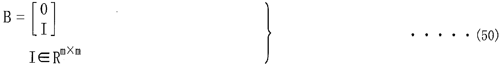
- An optimal regulator gain K is parameterized as equation (51). Further, a weighting matrix R is represented by equation (52). It is noted that "V" represents a regular matrix and "∑" represents a positive definite matrix.


- First, a matrix F1 is determined. From a point of view of a target responsiveness, a vector gi is set such that ti is mutually independent with respect to assigned poles s1...... sn-m in equation (53). Then, a matrix F1 is obtained in equation (54).
[Formulas 19]

- Next, the regular matrix V is determined. For simplification, for example, the regular matrix V is constituted by an identity matrix, since the regular matrix V is not particularly restricted as long as it is a regular matrix.
- Next, the positive definite matrix ∑ is determined based on equation (55) that is a linear matrix inequality. Specifically, a matrix, which is not smaller than ∑min, is selected as the positive definite matrix ∑, wherein ∑min is a minimum positive definite matrix that makes a positive definite matrix Y1 (> 0) feasible in the equation (55).
[Formula 20]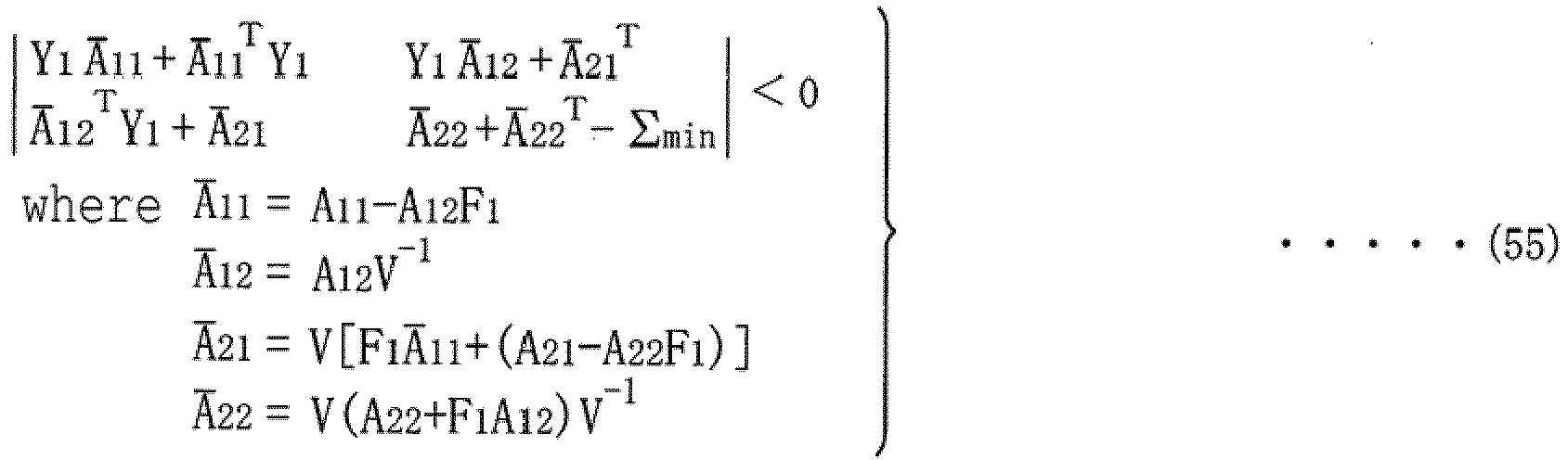
- There will be next described a design problem of an optimal servo system that enables an output y(t) of n-dimensional m-input m-output linear system, which is represented by equations (56), (57) and which is controllable and observable, to follow a current command value r(t) that is changed in steps. The term "controllable" means capable of moving a controlled object desirably by a current input. The term "observable" means capable of estimating a value of a state variable in a system through only an input and an output of a currently installed sensor. A state Xe is expressed by equation (58) wherein "r" represents a current command value, "x" represents a state after input of the current command value r, "u" represents an input, "x (with overline)" represents a steady state value of the state x, and "u (with overline)" represents a steady state value of the input u. Equation (61) represents an extended deviation system of an input v expressed by equation (59) and an output ye expressed by equation (60), while an evaluation function J is expressed by equation (62). The above-described design problem results in the optimal regulator problem that minimizes the evaluation function J. The optimal servo system is expressed by using equation (64) based on the solution v=-Ke * xe and equation (63). The control block diagram is realized by a structure of the
feedback controller portion 176a shown inFIG. 5 described above.
[Formulas 21]


- In the design of the optimal servo system in accordance with the ILQ design method, the results from the above-described equations (48)-(55) can be applied substantially directly to an extended system constituted by Ae, Be, Ce. Therefore, the optimal control rule Ke for the extended system is parameterized as equation (65). With the equation (65) being applied to the equation (64), the optimal control rule Ke is expressed by equation (66). The control block diagram corresponds to a structure of the
feedback controller portion 176b shown inFIG. 6 described above. However, the calculation is simplified since each system matrix of the extended system has a partial zero matrix.

- There will be described a process of determining parameters of the equation (65).
- First, a gain K is determined. From a point of view of a target responsiveness, a vector gi is set such that ti is mutually independent with respect to assigned poles s1......sn-m in equation (67). Then, the gain K is obtained in equation (68).
[Formulas 22]
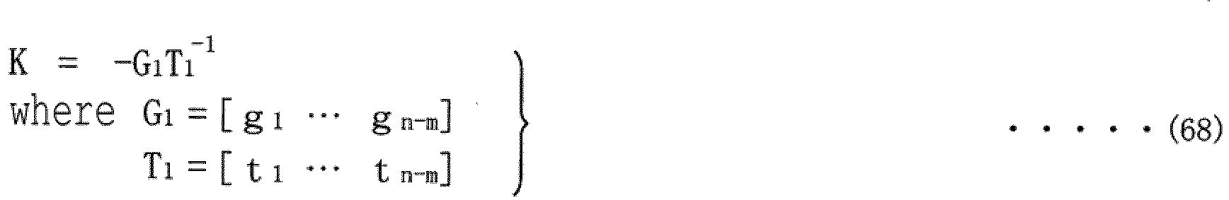
- Next, the regular matrix V is determined. As described above, the regular matrix V is constituted by an identity matrix, for example, for simplification.
- Next, the positive definite matrix ∑ is determined based on equation (69) that is a linear matrix inequality. Specifically, a matrix, which is not smaller than ∑min, is selected as the positive definite matrix ∑, wherein ∑min is a minimum positive definite matrix that makes a positive definite matrix Y (> 0) feasible in the equation (69).
[Formula 23]
- There will be described a calculation of the optimal control rule Ke with respect to the extended system (Ae, Be, Ce) expressed in equation (70). In the calculation, equation transform is made in a simplified manner in view of equation (71).
[Formulas 24]

- The gain K is obtained by pole assignment, and a positive definite matrix ∑(σ) is set to a positive-definite diagonal matrix that is larger than a certain lower limit. In the present embodiment, a assigned pole when σ→∞ is set to -1/0.0282*3, for the purpose of causing the control target value to follow a value dulled or moderated by a time constant Tf of 28.2[ms]. Further, the gains KF, KI (see
FIG. 5 ), which are equivalently transformed to an integral-type servo system, are obtained in equation (72). It is noted that Ae, Be, Ce are expressed by equations (73).
[Formulas 25]

- An optimality-assuring lower-limit ∑min is obtained as a minimum positive definite matrix ∑min (> 0) that makes a positive definite matrix Y1 (> 0) feasible in the equation (75) in which "Ak", "Bv", "Kv" are expressed by equations (74), and the optimality-assuring lower-limit ∑min is expressed by equation (76).
[Formulas 26]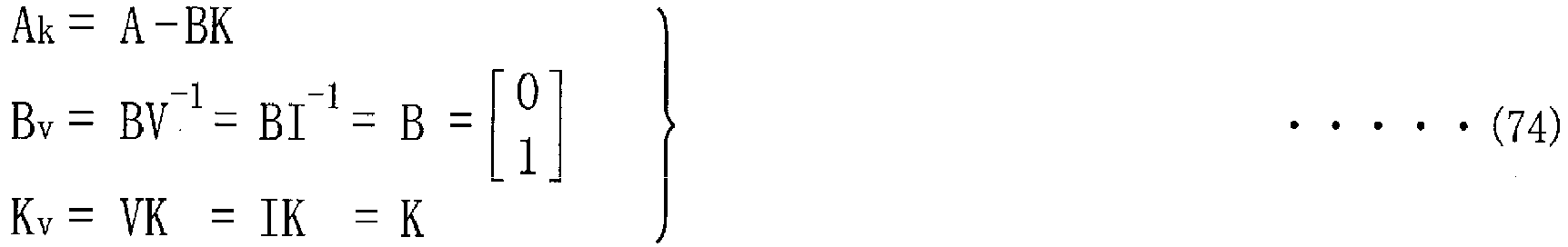


- Equations (77), (78) are established as is understood from
FIG. 6 that shows the control block diagram of thefeedback controller portion 176b that is designed in accordance with ILQ design method in the present embodiment. Equation (79) is obtained by applying the equation (78) to the equation (77). However, the equation (78) is transformed to equations (81) in view of equation (80). Equation (82) is obtained by applying the equations (81) to the equation (79).
[Formulas 27]


- The equation (82) is transformed to equation (83), by solving "Y(s)". Thus, the transfer function Gyd(s) of the
feedback controller portion 176b according to the present embodiment, which is shown inFIG. 6 , is expressed by equation (84).
[Formulas 28]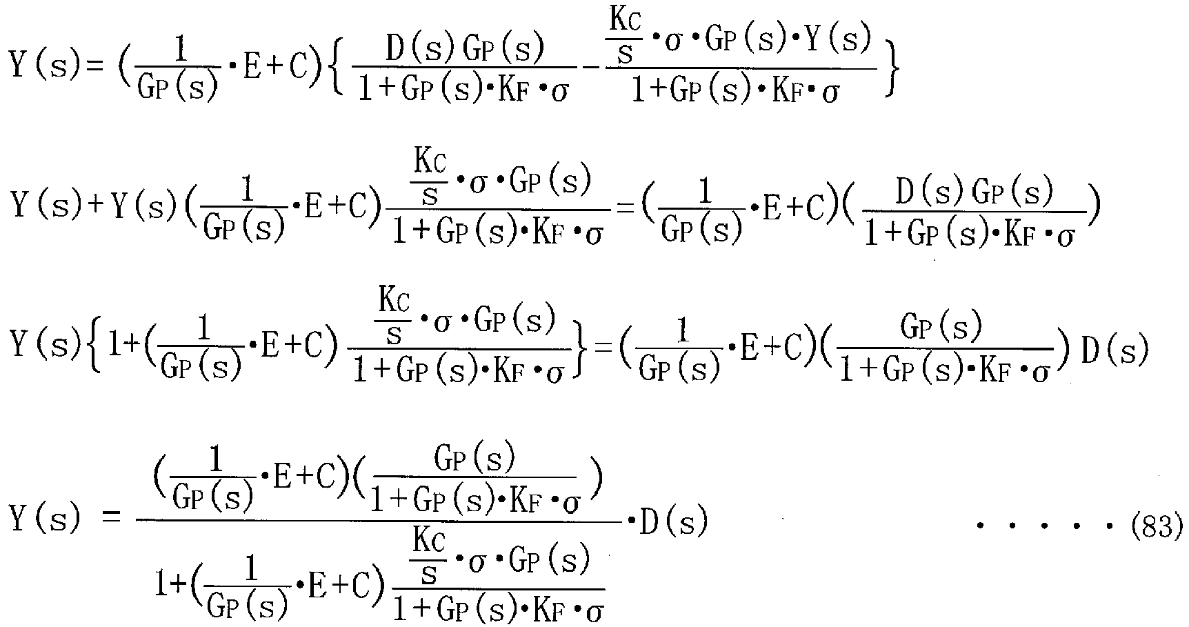

-
FIG. 20 is a flow chart showing a process of determining the parameters of the feedback control system in theelectronic control unit 170b shown inFIG. 6 , in accordance with the ILQ design method. The process shown by the flow chart inFIG. 20 is started to be executed and is executed once in a stage of design process of the feedback control system. - First, at step S100 corresponding to function of the
gain determining portion 192a, the gain K is calculated and determined. Then, step S100 is followed by step S110. - At step S110 corresponding to function of the regular-
matrix determining portion 192b, the regular matrix V is calculated and determined. Then, step S110 is followed by step S120. - At step S120 corresponding to function of the positive-definite-
matrix determining portion 192c, the positive definite matrix ∑ is calculated and determined. The process shown in the flow chart ofFIG. 20 is completed with the implementation of step S120. - The
feedback controller portion 176b calculates the output y, by applying a value obtained by subtracting the current signal Iact (that is supplied from the A/D converter ADC) from the current command value r(t) (that is supplied from the command-value setting portion 172), into the feedback control system in which the parameters such as the gain K and the positive definite matrix ∑, which are stored in theparameter storing portion 174, are applied. Then, thefeedback controller portion 176b outputs the calculated output y to thePWM portion 178. -
FIG. 21 is a flow chart showing a process of determining the controlled variable in the feedback control system in theelectronic control unit 170. For example, a change of an operation state of the vehicle triggers a start of the process shown in the flow chart ofFIG. 21 . - First, at step S200 corresponding to function of the command-
value setting portion 172, the current command value r(t) representing the control target value in the form of the average value of the driving current i(t) of the linear solenoid SSLT is set. Then, step S200 is followed by step S210. - At step S210 corresponding to functions of the
parameter storing portion 174 and thefeedback controller portion 176b, a deviation e of the current signal Iact of the current signal Iact as an observed value of the output y is subjected to a calculation made by the feedback control system represented by the control block diagram described in thefeedback controller portion 176b shown inFIG. 6 , whereby the output y is calculated. Then, step S210 is followed by step S220. - At step S220 corresponding to function of the
PWM portion 178, the PWM signal is generated based on the output y, and is outputted to the gate electrode of the drive transistor Tr. The process shown in the flow chart ofFIG. 21 is completed with the implementation of step S220. -
FIG. 22 is a functional block diagram showing the equivalent circuit of the linear solenoid SSLT, the drive circuit DRV of the linear solenoid SSLT and anelectronic control unit 370 of the linear solenoid SSLT. Theelectronic control unit 370, which is according to a conventional example, is designed by a two-degree-of-freedom control system. Theelectronic control unit 370 according to the comparative example is substantially the same as theelectronic control unit 170 according to the above-described first embodiment. However, theelectronic control unit 370 and theelectronic control unit 170 are different from each other in that itsfeedback controller portion 376 is designed by the two-degree-of-freedom control system in the comparative example while each of thefeedback controller portions - The
electronic control unit 370 includes the above-described command-value setting portion 172,parameter storing portion 174,PWM portion 178 andfeedback controller portion 376. - In the
parameter storing portion 174, parameters, which are applied to the feedback control system as described above, are stored in a stage of production of theparameter storing portion 174. It is noted that "the feedback control system" according to the comparative example is represented by a control block diagram described in thefeedback controller portion 376 shown inFIG. 22 . - The
feedback controller portion 376 causes the current command value r(t) supplied from the command-value setting portion 172 to be subjected to the feedback control using the current signal Iact representing the actual driving current i(t), and outputs, as the output y, the current command value r(t) subjected to the feedback control. The output y is outputted to thePWM portion 178. The output y is a signal representing the duty ratio dependent on the average driving current i(nτ) as a controlled variable that is described below. - As described above, the
feedback controller portion 376 shown inFIG. 22 has a construction of the feedback control that is constituted by the two-degree-of-freedom control system. Specifically, thefeedback controller portion 376 is constituted by a feedforward portion and a feedback portion. The feedforward portion multiplies a manipulated variable u by a transformation coefficient (feedforward gain Kff=50) for converting the manipulated variable u into the target duty ratio, wherein the manipulated variable u is obtained by applying a primary low-pass filter of a time constant Tf = 28.2[ms] to the current command value r(t). The feedback portion applies a deviation e of the current signal Iact (that is an observed value of the output y) from the manipulated variable u, to the transfer function GC(s) = Kfb/(TC*s+1). A value that is a sum of the manipulated variables calculated by the respective feedforward and feedback portions constitutes a final manipulated variable (parameter Kfb = 60, parameter TC= 0.150). The final manipulated variable is subjected to a calculation of the transfer function Gp(s), whereby the average driving current i(nτ) as the output y, i.e., the controlled variable is determined. - By the way, in
FIG. 22 , "d" represents a disturbance caused when thespool valve body 132 is moved by a hydraulic vibration or the like. The disturbance d is constituted by, for example, a counter electromotive force that is generated in the linear solenoid SSLT by movement of an iron core within a coil as the linear solenoid SSLT, which is made by movement of thespool valve body 132. Further, although the feedforward gain Kff is set to 50, it is preferable that the feedforward gain Kff is set based on the battery voltage Pb and the resistance Rz (that is a sum of the equivalent resistance Rs and the detection resistance Rd), for example, such that the feedforward gain Kff is set to [1/{(Pb)/(Rs+Rd)}], which is derived from the above-described equation (30). It is considered that, in thefeedback controller portion 376, there could be caused coupled vibration of the vibration of the spool valve body 132 (that is caused by the hydraulic vibration) and vibration of the driving current i(t). It is understood that the coupled vibration is likely to be generated, by analyzing characteristic of the transfer function Gyd(s) that represents a ratio of the output y to the disturbance d inFIG. 22 . It is noted that the coupled vibration is complicated vibration caused by two or more vibration systems that act or influence on each other. In coupled vibration, movement of vibrational state between a vibration system and another vibration system is seen. The coupled vibration could be a factor worsening convergence and responsiveness in controlling the vibration system to a certain control target value. - The transfer function Gyd(s) of the
feedback controller portion 376 shown inFIG. 22 is expressed by equation (85). Where the values of the above-described transfer function Gp(s) are used, a specific numerical solution of the transfer function Gyd(s) is expressed by equation (86).
[Formulas 29]

- The parameters of the
feedback controller portion 376 and characteristic change of the system will be described. The transfer function Gyu(s) representing a ratio of the output y to the manipulated variable u is expressed by equation (87). The numerical solution of the transfer function Gyu(s) is obtained by using specification values, and the transfer function Gyu(s) is expressed by equation (88). The numerical solution after a sufficient time has elapsed to the step input is expressed by equation (89). Therefore, since a static current accuracy is influenced by change of the parameter Kfb (= 60) of thefeedback controller portion 376, another parameter Tc of thefeedback controller portion 376 is changed.FIGS. 23A and 23B show Bode diagram of the transfer function Gyd(s) representing a ratio of the output y to the disturbance d in thefeedback controller portion 376 shown inFIG. 22 , and a result of a simulation in which the parameter Tc is changed.FIGS. 24A and 24B show Bode diagram of the transfer function Gyu(s) representing a ratio of the output y to the manipulated variable u in thefeedback controller portion 376 shown inFIG. 22 , and a result of a simulation in which the parameter Tc is changed. Thus, when the coupled vibration of hydraulic pressure is problematic, the responsiveness is worsened, but resonance can be avoided without the static current accuracy being sacrificed, by adjustment of the parameter Tc.
[Formula 30]


- Hereinafter, the
feedback controller portion 176b designed in accordance with the ILQ design method according to the present embodiment and thefeedback controller portion 376 designed by the two-degree-of-freedom control system according to the comparative example are compared in terms of characteristics. -
FIGS. 25A and 25B show Bode diagram of the transfer function Gyd(s) and a result of a simulation in which the resistance Rz is changed, wherein solid lines represent the result in thefeedback controller portion 176b expressed by equation (84) according to the present embodiment while broken lines represent the result in thefeedback controller portion 376 expressed by equation (86) according to the comparative example.FIG. 25A represents the frequency characteristic of the gain of the transfer function Gyd(s).FIG. 25B represents the frequency characteristic of a phase of the transfer function Gyd(s). -
FIG. 25A indicates, in thefeedback controller portion 376 according to the comparative example, a resonance frequency range is changed with respect to change of the resistance Rz, which is caused by change of the equivalent resistance Rs that constitutes a part of the resistance Rz wherein the change of the equivalent resistance Rs is changed with change of temperature of the linear solenoid SSLT. In thefeedback controller portion 376 according to the comparative example, there is a resonance frequency range with the gain exceeding 0[dB], at about 300[rad/s]. On the other hand, in the closed-loop system of thefeedback controller portion 176b according to the present embodiment, although the gain characteristic is changed, there is no a range in which the gain exceeds 0[dB], throughout all frequency ranges, so that it is understood that the coupled vibration is unlikely to occur. Thus, as compared with thefeedback controller portion 376 according to the comparative example, thefeedback controller portion 176b according to the present embodiment provides a higher robustness against change of the resistance Rz. -
FIG. 26 shows a simulation result regarding the static current accuracy (absolute error and relative error) in thefeedback controller portion 176b according to the present embodiment.FIG. 26 shows also a simulation result regarding the static current accuracy (absolute error and relative error) in thefeedback controller portion 376 according to the comparative example, for reference. In thefeedback controller portion 376 according to the comparative example, since the driving current i(t) is converged to a vicinity of the control target value by increasing the feedback gain, the error is increased (the error ratio is substantially constant) with increase of the current command value r(t) corresponding to the control target value. On the other hand, in thefeedback controller portion 176b according to the present embodiment, which is a servo system oftype 1, although the deviation is theoretically 0[A], the error of about 0.1[mA] is seen in any level of the current command value r(t) corresponding to the control target value, due to a discretization error or the like, in the simulation. -
FIGS. 27A and 27B show Bode diagram of the transfer function G(s) that represents a ratio of the output y to the current command value r in thefeedback controller portion 176b according to the present embodiment, and a simulation result. From the Bode diagram ofFIGS. 27A and 27B , it is understood that the control system according to the present embodiment, which is designed by the ILQ design method, exhibits a gain characteristic of a monotonic decrease of a closed loop system and is constituted by a closed loop characteristic without resonance mode. -
FIG. 28 is a view explaining a deviation and a feedback correction amount in the step response in thefeedback controller portion 176b according to the present embodiment. As shown inFIG. 28 , the current command value r(t) corresponding to the control target value is changed in step from 0[A] to 1.0[A] at a point 0[s] of time, before the current command value r(t) is dulled or moderated. On the other hand, after being moderated, the current command value r(t) corresponding to the control target value is moderated with the time constant Tf being 28.2[ms], wherein the positive definite matrix ∑ as the parameter for tuning is set to 300. As is understood fromFIG. 28 , a sufficiently high responsiveness to the current command value r(t) (after the moderation) is performed without overshooting. -
FIGS. 29A and 29B show a simulation result of a response to a step change (reduction) of the battery voltage Pb in thefeedback controller portion 176b according to the present embodiment.FIGS. 29A and 29B show also a simulation result of a response to a step change (reduction) of the battery voltage Pb in thefeedback controller portion 376 according to the comparative example, for reference.FIG. 29A shows change of the battery voltage Pb with respect to time. At a point 0[s] of time, the battery voltage Pb which had been 15[V] is reduced at step to 12[V].FIG. 29B shows a change of the average lave of the driving current i(t) when the battery voltage Pb is changed at step as shown inFIG. 29A .FIGS. 30A and 30B show a simulation result of a response to a step change (increase) of the battery voltage Pb in thefeedback controller portion 176b according to the present embodiment.FIGS. 30A and 30B show also a simulation result of a response to a step change (increase) of the battery voltage Pb in thefeedback controller portion 376 according to the comparative example, for reference.FIG. 30A shows change of the battery voltage Pb with respect to time. At a point 0[s] of time, the battery voltage Pb which had been 12[V] is increased at step to 15[V].FIG. 30B shows a change of the average lave of the driving current i(t) when the battery voltage Pb is changed at step as shown inFIG. 30A . The battery voltage Pb is used also as a power supply voltage for an air-conditioning equipment (such as air conditioner) and an audio equipment (such as radio), so that the battery voltage Pb could be changed in step upon switching on/off of the air-conditioning equipment and/or the audio equipment. As is estimated from the transfer function Gyd(s) representing the ratio of the output y to the disturbance d, the driving current i(t) is converged while being fluctuated in thefeedback controller portion 376 according to the comparative example, while the deviation is smoothly reduced to zero in thefeedback controller portion 176b according to the present embodiment. - In the
electronic control unit 170b according to the present embodiment, the feedback control is executed with the feedback control system having the parameters that are determined in accordance with the ILQ design method, wherein the gain of the transfer function Gyd(s), which represents the ratio of the output y to the disturbance d in the feedback control system, is lower than 0[dB] throughout all frequency ranges. With use of the feedback control system having the parameters determined in accordance with the ILQ design method, it is possible to reduce the adapting steps of adapting the parameters for each of various levels of the state value such as the power supply voltage, which is the responsiveness factor. Further, in the execution of the feedback control with the feedback control system, the driving current i(t) is controlled such that the driving current i(t) is converged to the control target value (corresponding to a control command value) at a high responsiveness with respect to step change of the control target value and step change of the battery voltage Pb of the drive circuit DRV of the linear solenoid SSLT, without causing the control system to be vibrated and without causing coupled vibration in the linear solenoid SSLT. - In the
electronic control unit 170b according to the present embodiment, the linear solenoid SSLT is provided in the linear solenoid valve SLT that is configured to supply the control hydraulic pressure PS to the line-pressure regulator valve 110 for controlling the line pressure PL generated by the line-pressure regulator valve 110 in thehydraulic control unit 18 of the vehicleautomatic transmission 14. Owing to this arrangement, the control hydraulic pressure PS, which is for controlling the line pressure PL generated by the line-pressure regulator valve 110 provided in the vehicleautomatic transmission 14, is controlled to provide a high responsiveness without its vibration, whereby the line pressure PL generated by the line-pressure regulator valve 110 is also controlled to a high response without its vibration. - In the
electronic control unit 170b according to the present embodiment, the driving current i(t) supplied to the linear solenoid SSLT is controlled by the input voltage vin(t) that is obtained by causing the battery voltage Pb to be subjected to the ON-OFF control based on the PWM signal, wherein the electric circuit of the linear solenoid SSLT, through which the driving current i(t) flows, is approximated by the series circuit of the resistance Rz and the inductance L, wherein the circuit equation related to the instantaneous value of the driving current i(t) flowing through the series circuit is formulated, wherein the equation related to the average driving current i(nτ) as the controlled variable for controlling the driving current i(t) is formulated, wherein the equation related to the average driving current i(nτ) is derived as the recurrence equation, wherein the recurrence equation is solved, and the solved recurrence equation is linearized by the approximation equation, and wherein the transfer function of the feedback control is derived from the linearized equation related to the controlled variable, and the derived transfer function is used to determine the average driving current i(nτ). Thus, the transfer function, which is accurately linearized and approximated, is derived whereby the average driving current i(nτ) as the controlled variable is determined by calculations, so that it is possible to reduce the adapting steps of adapting the parameters for each of various levels of the state value such as the power supply voltage, which is the responsiveness factor. For example, it is possible to reduce the adapting steps for adapting the parameters for change of the battery voltage Pb that corresponds to the power supply voltage of the linear solenoid SSLT and change of the control target value of the driving current i(t) of the linear solenoid SSLT. - In the
electronic control unit 170b according to the present embodiment, the circuit equation is formulated as the equation (1), the equation related to the controlled variable that is the average value of the driving current i(t) in an n-th period (n: natural number) is formulated as the equation (2), the recurrence equation is formulated as the equation (3), and the approximation equation is formulated as the equation (4), where "t[s]" represents the time, "τ[s]" represents each driving period of the PWM signal, "τ1[s]" represents the ON time that is a length of time for which the driving current (i(t)) is supplied to the linear solenoid SSLT in each driving period, "Pb[V]" represents the battery voltage, and "L(H)" represents the inductance. Thus, the transfer function, which is accurately linearized and approximated, is derived by the equations (3), (4) whereby the controlled variable is determined by calculations, so that it is possible to reduce the adapting steps. -
FIG. 31 is a functional block diagram showing the equivalent circuit of the linear solenoid SSLT and the drive circuit DRV of the linear solenoid SSLT, which are shown inFIG. 4 , and anelectronic control unit 170c for the linear solenoid SSLT, which is designed in accordance with the ILQ design method and is constructed according to this second embodiment of the invention, for controlling parameter correction. Although theelectronic control unit 170c according to the second embodiment is substantially identical with theelectronic control unit 170b according to the above-described first embodiment in terms of construction, theelectronic control unit 170c is different from theelectronic control unit 170b in that the parameters of the feedback control system are corrected depending on actual values of the resistance Rz and the inductance L of the electric circuit of the linear solenoid SSLT through which the driving current i(t) flows. Therefore, the differences will be mainly described, and the same reference signs as used in the above-described first embodiment will be used to identify the functionally corresponding elements, with descriptions thereof being omitted as needed. It is noted that the equivalent circuit of the linear solenoid SSLT and the drive circuit DRV of the linear solenoid SSLT, which are shown inFIG. 31 , have been described with reference toFIG. 6 , and descriptions thereof will not be provided. - The
electronic control unit 170c includes, in addition to the above-described command-value setting portion 172,parameter storing portion 174,feedback controller portion 176c andPWM portion 178, a measuringportion 180, a calculatingportion 182 and a correctingportion 184 that are provided for controlling the parameter correction. Theelectronic control unit 170c calculates actual values of the resistance Rz and the inductance L of the electric circuit of the linear solenoid SSLT through which the driving current i(t) flows, and corrects the parameters related to the feedback control. Theelectronic control unit 170c receives various input signals from various sensors provided in the vehicle, such as: the above-described output signal indicative of the throttle opening degree TA; output signal indicative of the engine rotational speed Ne; output signal indicative of the input-shaft rotational speed Nin; output signal indicative of the counter-shaft rotational speed Nc, i.e., the vehicle running speed Vc; output signal indicative of the operation position Pst of theshift lever 84; output signal indicative of the temperature Thoil of the working fluid in thehydraulic control unit 18; and an output signal which is supplied from avoltage sensor 74 configured to detect a battery voltage Pb at the terminal Bt and which is indicative of the battery voltage Pb. - The command-
value setting portion 172 sets the current command value r(t) that represents the control target value in the form of the average value of the driving current i(t) of the linear solenoid SSLT, as described above. In control of correction of the parameters, the command-value setting portion 172 keeps outputting, to thefeedback controller portion 176c, the current command value r(t) in the form of a certain current command value Rpd[A] for at least a given length Tpd[s] of time. It is preferable that the certain current command value Rpd is a value higher than a normal value of the current command value r(t) so that the resistance Rz and the inductance L can be accurately calculated. The command-value setting portion 172 outputs, to the measuringportion 180, a timer signal TM as an output start signal indicative of start of output of the current command value r(t). Further, when the given length Tpd[s] of time has elapsed after the start of output of the current command value Rpd, the command-value setting portion 172 outputs the timer signal TM as an output stop signal to the measuringportion 180. It is noted that the certain current command value Rpd is a value which is obtained by experimentation or determined by an appropriate design theory such that the driving current i(t) of the linear solenoid SSLT is converged when the given length Tpd of time elapses. Further, the given length Tpd of time is a length of time within which the instantaneous value of the driving current i(t) is converged in case of the certain current command value Rpd, and is obtained by experimentation or determined by an appropriate design theory, from the nominal values of the battery voltage Pb, resistance Rz, inductance L and the designed values of the driving period τ and ON time τ1 of the drive transistor Tr, such that the driving current i(t) is converged within the given length Tpd of time even if actual values are changed from the above nominal value and designed values within expected ranges due to aging for years or under unusual temperature condition. - The
parameter storing portion 174,feedback controller portion 176c andPWM portion 178 have the functions as described above with reference toFIG. 6 . - When the output start signal in the form of the timer signal TM is supplied from the command-
value setting portion 172 to the measuringportion 180, the measuringportion 180 obtains the battery voltage Pb from thevoltage sensor 74, and obtains the current signal Iact from the A/D converter ADC. The measuringportion 180 measures the average lave and minimum instantaneous current values Imin of the current signal Iact, from the obtained current signal Iact. The average lave of the current signal Iact is measured, for example, by calculating a moving average of the current signal Iact for a length of time corresponding to the period τ[s] that represents each driving period τ of the PWM signal. The measured average lave is updated. The minimum instantaneous current values Imin of the current signal Iact is measured, for example, by calculating a minimum value of the current signal Iact in each driving period τ of the PWM signal. The calculated minimum instantaneous current values Imin is updated. The measuringportion 180 obtains the ON time τ1, OFF time τ2 and driving period τ of the drive transistor Tr, for example, from the output y calculated by thefeedback controller portion 176c and command values such as the PWM signal generated by thePWM portion 178. When the output stop signal in the form of the timer signal TM is supplied from the command-value setting portion 172 to the measuringportion 180, the measuringportion 180 determines the average lave and the minimum instantaneous current values Imin, which the measuringportion 180 have measured and updated, as an average Iavec and a minimum instantaneous current value Iminc in the converged state, respectively. After having determined the average Iavec and the minimum instantaneous current value Iminc in the converged state, the measuringportion 180 outputs a command signal to the calculatingportion 182. - When the command value is supplied from the measuring
portion 180 to the calculatingportion 182, the calculatingportion 182 calculates the resistance Rz in accordance with the above-described equation (5) and calculates the inductance L in accordance with the above-described equation (6). After calculating the resistance Rz and the inductance L, the calculatingportion 182 outputs a command signal to the correctingportion 184. - There will be described reasons why the resistance Rz is calculated in accordance with the equation (5) and the inductance L is calculated in accordance with the equation (6).
- The converged driving current a∞, which is expressed by the above-described equation (30), is the average Iavec in the converged state, so that the equation (5) is derived by transforming the equation (30) to an equation regarding the resistance Rz.
- Equation (90) regarding the minimum instantaneous current value Iminc in the converged state is established from the above-described equation (15) and a superposition principle. The equation (90) is transformed to equation (91) that is identical with the equation (6).
[Formulas 31]

- By the way, the equation (6) is not formulated to an equation in which the inductance L is solved.
FIG. 32 is a view showing a relationship between the inductance L of the electric circuit through which the driving current i(t) flows, and the minimum instantaneous current value Iminc in the converged state.FIG. 32 shows the relationship between the inductance L and the minimum instantaneous current value Iminc when the inductance L is in a range of 0-0.1[H], wherein the specification values are the battery voltage Pb = 15[V], the resistance Rz = 5.8[Ω] {= 5.3[Ω] (equivalent resistance Rs) + 0.5[Ω] (detection resistance Rd)}, the driving period τ = 1/3*10-2[s] and the OFF time τ2=τ/2[s]. As is understood fromFIG. 32 , the minimum instantaneous current value Iminc is a monotonically increasing function of the inductance L. Therefore, the inductance L can be obtained through a convergence calculation using an iterative method such as Newton's method and binary search method. - When the output signal is supplied from the calculating
portion 182 to the correctingportion 184, the correctingportion 184 corrects the parameters used in thefeedback controller portion 176c, depending on the calculated resistance Rz and inductance L. The correctingportion 184 updates the parameters stored in theparameter storing portion 174, by rewriting them into the corrected ones, so that the feedback control is executed based on the corrected parameters in thefeedback controller portion 176c. -
FIG. 33 is a flow chart showing a process for control of correction of the parameters in theelectronic control unit 170c shown inFIG. 31 . In the present embodiment, this process shown in the flow chart ofFIG. 33 is started, for example, upon an inspection made during a process of manufacturing thehydraulic control unit 18 that is provided to control theautomatic transmission 14. However, the process may be started, for example, when an inspection is made when thehydraulic control unit 18 including the linear solenoid SSLT is attached to the vehicle after having being repaired, when a total traveled distance of the vehicle exceeds a certain distance (e.g. 10,000km) for checking aging, or when an unusual condition such as low or high temperature comes up. Since the process shown in the flow chart ofFIG. 33 is completed in a short length of time such as 0.1[s], the process is executed during a running state of the vehicle when the total traveled distance of the vehicle exceeds the certain distance, for example, such that the running is not affected even by supply of the driving current i(t) to the linear solenoid SSLT. The unusual condition is detected, for example, through the output signal which is supplied from theoil temperature sensor 88 which is indicative of the working-fluid temperature Thoil, for example, when theengine 10 is started after having been stropped for a large length of time in a cold area, or when the linear solenoid SSLT is heated to a high temperature by an increase of the working fluid which is caused by running of the vehicle on an uphill for a larger length of time. - The process is initiated with step S300 corresponding to function of the command-
value setting portion 172, which is implemented to output the certain current command value Rpd as the current command value r(t) for at least a given length Tpd of time. Step S300 is followed by step S310. - At step S310 corresponding to function of the measuring
portion 180, the battery voltage Pb, the average Iavec in the converged state, the minimum instantaneous current value Iminc in the converged state and the driving period τ, ON time τ1 and OFF time τ2 of the drive transistor Tr are obtained or measured. Step S310 is followed by step S320. - At step S320 corresponding to function of the calculating
portion 182, the resistance Rz is calculated in accordance with the equation (5). Step S320 is followed by step S330. - At step S330 corresponding to function of the calculating
portion 182, the inductance L is calculated in accordance with the equation (6). Step S330 is followed by step S340. - At step S340 corresponding to function of the correcting
portion 184, the parameters used in thefeedback controller portion 176c are corrected based on the calculated resistance Rz and inductance L. The process shown in the flow chart ofFIG. 33 is completed with the implementation of step S340. - In the
electronic control unit 170b according to the second embodiment, the driving current i(t) supplied to the linear solenoid SSLT is controlled by the battery voltage Pb and the ON time τ1 and OFF time τ2 of the driving period τ, wherein the resistance Rz[Ω] of the electric circuit of the linear solenoid SSLT, through which the driving current i(t) flows, is calculated in accordance with equation (5), and the inductance L[H] of the electric circuit is calculated in accordance with equation (6), where "Iavec[A]" represents the average value of the driving current i(t) in the converged state, and "Iminc[A]" represents the minimum instantaneous current value of the driving current i(t) in the converged state, and wherein the parameters are corrected depending on the resistance Rz[Ω] and the inductance L[H] that are calculated in accordance with the respective equations (5) and (6). Thus, the actual values of the resistance Rz and the inductance L even after aging for years after production of the vehicle or even under unusual condition such as low or high temperature can be calculated by the equations (5) and (6). Thus, even where the equivalent resistance Rs and the equivalent inductance Ls of the linear solenoid SSLT and the detection resistance Rd of the drive circuit DRV have been changed with aging for years after production of the vehicle or even where the equivalent resistance Rs, equivalent inductance Ls and detection resistance Rd are considerably different, under unusual condition such as low or high temperature, from in a normal condition, the feedback control of the linear solenoid SSLT can be executed such that the driving current i(t) is controlled to provide a high responsiveness without its fluctuation, without causing coupled vibration in the linear solenoid SSLT. - As described above,
FIG. 1 shows also the construction of the hydraulic variable valve-timing apparatus 200 including theelectronic control unit 270 according to this third embodiment of the invention. In the above-described first and second embodiments, the present invention is applied to theelectronic control unit 170 of the linear solenoid SSLT of thehydraulic control unit 18 configured to control shifting actions of theautomatic transmission 14. Unlike in the first and second embodiments, in the third embodiment, the invention is applied to the hydraulic variable valve-timing apparatus 200. The same reference signs as used in the above-described first and second embodiments will be used to identify the functionally corresponding elements, and descriptions thereof are omitted as needed. - The variable valve-
timing apparatus 200 includes anintake cam shaft 204, a variable valve-timing mechanism 202 (VVT-i: Variable Valve Timing-intelligent), ahydraulic control unit 232 and the above-describedelectronic control unit 270. - The
engine 10 includesintake valves 208 that are to be opened and closed at suitable timing withrespective cams 206 being driven, so that a fuel-air mixture is drawn into respective cylinders of theengine 10 at given timing. Each of thecams 206 has, in its cross section, a generally egg shape that is defined by a circle having a smoothly protruded part. A rotary motion of eachcam 206 is converted into a reciprocating motion of thecorresponding intake valve 208, whereby theintake valve 208 is opened and closed. Where theengine 10 includes a plurality of cylinders, theintake cam shaft 204 is provided with the plurality ofcams 206. A rotation of thecrank shaft 26 is transmitted to asprocket 220 that is rotatably held at an axis CL2, for example, via asprocket 24 provided on thecrank shaft 26 and atiming chain 212. Arotary member 210 is provided to be rotated at the same rotational speed as thesprocket 220. As described below, a rotational position or phase of therotary member 210 relative to thesprocket 220 is adjustable. Theintake cam shaft 204 and therotary member 210 are fixed to each other, and are rotatably held at the axis CL2. Where theengine 10 is a four-cycle engine, eachcam 206 is rotated once and thecrank shaft 26 is rotated twice during four strokes (i.e., intake stroke, compression stroke, explosion stroke and exhaust stroke) of theengine 10, so that thesprocket 220 has a diameter twice as large as a dimeter of thesprocket 24. - The variable valve-
timing mechanism 202 includes therotary member 210 fixed to an end portion of theintake cam shaft 204, and thesprocket 220 rotatably held in the end portion of theintake cam shaft 204. As described below, the variable valve-timing mechanism 202 is configured to adjust the rotational phase of theintake cam shaft 204 by a hydraulic pressure supplied from thehydraulic control unit 232, whereby opening/closing timing of theintake valves 208 of theengine 10 is adjusted. - Each of
FIGS. 34-36 is a view showing constructions of main portions of the variable valve-timing apparatus 200 including theelectronic control unit 270 according to the third embodiment. InFIG. 34 , a cross section of each of thesprocket 220 and therotary member 210 as seen in a direction of the axis CL2 is shown, and a cross section of each of theintake cam shaft 204, a valve unit 238 (described below) and an actuator 234 (described below) as seen in the direction of the axis CL2 is also shown.FIG. 34 shows a case in which the rotational phase of theintake cam shaft 204 is adjusted to be delayed or retarded. Therotary member 210, which is fixed to theintake cam shaft 204, includes a pair ofvane portions rotary member 210. Therotary member 210 is received inside a cylindrical core potion of thesprocket 220 in which an advance-side fluid chamber 220a, a retard-side fluid chamber 220b andfluid chambers side fluid chamber 220a and thefluid chamber 220c are located in respective opposite sides of thevane portion 210a in a circumferential direction of thesprocket 220 such that the advance-side fluid chamber 220a is located on a rear side of thefluid chamber 220c in a rotation direction Fr of thesprocket 220. The retard-side fluid chamber 220b and thefluid chamber 220d are located in respective opposite sides of thevane portion 210b in the circumferential direction such that the retard-side fluid chamber 220b is located on a front side of thefluid chamber 220d in the rotation direction Fr. Each of the advance-side fluid chamber 220a, retard-side fluid chamber 220b andfluid chambers chambers 220a-220d is controlled by thehydraulic control unit 232, as described below. - The
hydraulic control unit 232 includes, in addition to the above-describedactuator 234 andvalve unit 238,check valves fluid supply passage 222, afluid supply sub-passages fluid discharge passages actuator 234 includes alinear solenoid 234a, apressing portion 234b, asolenoid housing 234c and adrive circuit portion 234d. In theactuator 234, the driving current i(t) of thelinear solenoid 234a is controlled by the PWM signal supplied from theelectronic control unit 270 to thedrive circuit portion 234d, and thepressing portion 234b disposed in thesolenoid housing 234c is moved, by a thrust based on a driving signal SD2 corresponding to the driving current i(t), in a direction of the axis CL2. Thevalve unit 238 includes a cylindricalmain body 240, aspool valve body 242, aspring 244 and abottom end portion 246. Thespool valve body 242 is received in a through-hole 240d which is formed in the cylindricalmain body 240 and which extends in the direction of the axis CL2, such that thespool valve body 242 is movable in the direction of the axis CL2. Thespring 244 is held in thespool valve body 242 by means of a snap ring that is fixedly disposed on thespool valve body 242, such that thespool valve body 242 is constantly forced or biased by thespring 244 in a direction toward theactuator 234. With movement of thepressing portion 234b of theactuator 234 in the direction of the axis CL2, thespool valve body 242, which is disposed in the cylindricalmain body 240, is moved in the direction of the axis CL2. Depending on a position of thespool valve body 242 relative to the cylindricalmain body 240 in the direction of the axis CL2, the working fluid is selectively supplied and discharged through thefluid supply passage 222,fluid supply sub-passages fluid discharge passages valve unit 238 to thefluid supply passage 222, an output pressure PW2, which is to be supplied from thevalve unit 238 to thefluid discharge passage 228, and an output pressure PW3, which is to be supplied from thevalve unit 238 to thefluid discharge passage 230, are controlled, whereby the working fluid is supplied to or discharged from the advance-side fluid chamber 220a, retard-side fluid chamber 220b andfluid chambers - Like the
electronic control unit 170 according to the above-described first embodiment, theelectronic control unit 270 includes a so-called microcomputer, and is configured to control the variable valve-timing apparatus 200, by causing the CPU to process various input signals, according to control programs stored in the ROM, while utilizing a temporary data-storage function of the RAM. Theelectronic control unit 270 corresponds to "control apparatus" recited in the appended claims. - The
electronic control unit 270 receives an output signal which is supplied from a crankposition sensor 70 configured to detect a rotation angle of thecrank shaft 26 and which is indicative of a crank-shaft rotation angle Pcra[rad] corresponding to the rotation angle of thecrank shaft 26, and an output signal which is supplied from acam position sensor 72 configured to detect a rotation angle of theintake cam shaft 204 and which is indicative of a cam rotation angle Pcam[rad] corresponding to the rotation angle of theintake cam shaft 204. Theelectronic control unit 270 outputs the PWM signal to thedrive circuit portion 234d of theactuator 234, as described above. - The
electronic control unit 270 has substantially the same control functions as those of theelectronic control unit 170b according to the above-described first embodiment, which is described with reference to the functional block diagram ofFIG. 6 . Thelinear solenoid 234a of theactuator 234 has an equivalent circuit which is identical with that of the linear solenoid SSLT in the first embodiment and which is expressed by the RL series circuit constituted by the equivalent inductance Ls and the equivalent resistance Rs. Thedrive circuit portion 234d of theactuator 234 has an equivalent circuit which is identical with the drive circuit DRV in the first embodiment and which is constituted by the terminal Bt (to which the battery voltage Pb is supplied), drive transistor Tr, detection resistance Rd, operational amplifier AMP and A/D converter ADC. - In
FIG. 34 , arrow Fr indicates a direction of rotation of thesprocket 220, which is to be made when rotation of thecrank shaft 26 is transmitted to thesprocket 220 via thesprocket 24 and thetiming chain 212. The driving current i(t) flowing through thelinear solenoid 234a is controlled by the PWM signal outputted from theelectronic control unit 270, whereby thepressing portion 234b of theactuator 234 is moved against a biasing force of thespring 244 so as to be positioned in such a positon that brings adischarge hole 242a into communication with afluid hole 240c. In this instance, the working fluid from the advance-side fluid chamber 220a of thesprocket 220 is caused to flow in a direction indicated by arrows through thefluid supply sub-passage 224,fluid discharge passage 228,fluid hole 240c anddischarge hole 242a, and is discharged to afluid passage 242b which is formed in thespool valve body 242 and which extends in the direction of the direction of the axis CL2. - Thus, with the
sprocket 220 being forced to be rotated in the direction of arrow Fr, the working fluid in the advance-side fluid chamber 220a is discharged by thevane portion 210a, and the working fluid in thefluid chamber 220d is caused to flow into thefluid chamber 220c via agroove 210c, thereby causing therotary member 210 to be rotated in a direction opposite to the direction of arrow Fr. Consequently, the rotational phase of theintake cam shaft 204 connected to therotary member 210 is delayed or retarded relative to the rotational phase of thesprocket 220 that is mechanically associated with thecrank shaft 26, whereby the opening/closing timing of theintake valves 208 is delayed or retarded. -
FIG. 35 is a view showing the construction of the main portions of the variable valve-timing apparatus 200 including theelectronic control unit 270, in a case in which the rotational phase of theintake cam shaft 204 is adjusted to be advanced. The supply of the PWM signal from theelectronic control unit 270 to thedrive circuit portion 234d is stopped whereby theactuator 234 is controlled such that the driving current i(t) is not supplied to thelinear solenoid 234a. With the driving current i(t) being not supplied to thelinear solenoid 234a, thespool valve body 242 disposed in the cylindricalmain body 240 is moved, by the biasing force of thespring 244, in the direction of the direction of the axis CL2 in thevalve unit 238. Thus, thespool valve body 242 is positioned in such a position that brings thedischarge hole 242a of thespool valve body 242 into communication with afluid hole 240a. In this instance, the working fluid from the retard-side fluid chamber 220b of thesprocket 220 is caused to flow in a direction indicated by arrows through thefluid supply sub-passage 226,fluid discharge passage 230,fluid hole 240a anddischarge hole 242a, and is discharged to thefluid passage 242b. - Thus, with the
sprocket 220 being forced to be rotated in a direction opposite to the direction of arrow Fr, the working fluid in the retard-side fluid chamber 220b is discharged by thevane portion 210b, and the working fluid in thefluid chamber 220c is caused to flow into thefluid chamber 220d via thegroove 210c, thereby causing therotary member 210 to be rotated in the direction of arrow Fr. Consequently, the rotational phase of theintake cam shaft 204 connected to therotary member 210 is advanced relative to the rotational phase of thesprocket 220 that is mechanically associated with thecrank shaft 26, whereby the opening/closing timing of theintake valves 208 is advanced. -
FIG. 36 is a view showing the construction of the main portions of the variable valve-timing apparatus 200 including theelectronic control unit 270, in a case in which the rotational phase of theintake cam shaft 204 is adjusted to be maintained. When the cam rotation angle Pcam becomes a target angle, thespool valve body 242 is moved by movement of thepressing portion 234b of theactuator 234 which is made by the PWM signal outputted to thedrive circuit portion 234d from theelectronic control unit 270, and thespool valve body 242 is positioned in such a position that brings thedischarge hole 242a of thespool valve body 242 into communication with afluid hole 240b, while isolating thedischarge hole 242a from thefluid holes fluid discharge passages fluid passage 242b. In this instance, the working fluid in the advance-side fluid chamber 220a and the working fluid in the retard-side fluid chamber 220b are not discharged since thefluid holes spool valve body 242, while thefluid chambers fluid chambers fluid supply passage 222. Further, the working fluid in thefluid supply passage 222 is supplied to the advance-side fluid chamber 220a and the retard-side fluid chamber 220b, through thecheck valves fluid supply sub-passage intake cam shaft 204 connected to therotary member 210 relative to the rotational phase of thesprocket 220 that is mechanically associated with thecrank shaft 26, whereby the opening/closing timing of theintake valves 208 is determined. It is noted that the working fluid is supplied to thefluid supply passage 222 from thehydraulic pump 90 via afluid hole 258, afluid chamber 256 that is provided in an end portion of theintake cam shaft 204, afluid hole 262, acheck valve 252, afluid passage 260 and the above-describedfluid hole 240b. - The feedback control, which is executed by the
electronic control unit 270 for thedrive circuit portion 234d is substantially the same as the feedback control executed by theelectronic control unit 170b for the drive circuit DRV in the above-described first embodiment. That is, the PWM signal corresponding to the current command value r(t) is supplied from theelectronic control unit 270 to thedrive circuit portion 234d, and the current signal Iact representing the driving current i(t) actually supplied from thedrive circuit portion 234d to thelinear solenoid 234a, is received by theelectronic control unit 270. Theelectronic control unit 270 executes the feedback control with use of the feedback control system having the parameters that are determined in substantially the same manner as in the above-described first embodiment. - In the
electronic control unit 270 according to the third embodiment, thelinear solenoid 234a is provided in theactuator 234, wherein, in thehydraulic control unit 232 for controlling the variable valve-timing mechanism 202 configured to adjust the opening/closing timing of theintake valves 208 of theengine 10, thevalve unit 238 of thehydraulic control unit 232 is caused to supply, to the variable valve-timing mechanism 202, the output pressures PW1, PW2, PW3 each of which corresponds to the signal pressure whose magnitude corresponds to the driving current i(t) that is determined through the feedback control, for generating the hydraulic pressure for adjusting the opening/closing timing. Owing to this arrangement, the signal pressure, which is supplied from thevalve unit 238 to the variable valve-timing mechanism 202, can be controlled to provide a high responsiveness without its fluctuation, whereby the adjustment of the opening/closing timing by the variable valve-timing mechanism 202 can be also controlled to provide a high responsiveness without its vibration. - While the preferred embodiments of this invention have been described in detail by reference to the drawings, it is to be understood that the invention may be otherwise embodied.
- In the above-described second embodiment, the parameters of the feedback control system are corrected only based on the calculated resistance Rz and inductance L of the electric circuit through which the driving current i(t) flows. For example, the parameters of the feedback control system may be corrected based on the calculated values of the resistance Rz and the inductance L and also the nominal values of the resistance Rz and the inductance L. In this modification, a weighting may be given to the nominal value and the calculated value, for example, such that a weighting ratio of 7:3 is given to the nominal value and the calculated value whereby the parameters of the feedback control system is corrected based on a value corresponding to (0.7* nominal value + 0.3* calculated value) of the resistance Rz and a value corresponding to (0.7* nominal value + 0.3* calculated value) of the inductance L. In this modification, even if the calculated value is erroneously deviated from the actual value, the nominal value that is given the higher weighting is reflected largely on the correction of the parameters, so that the feedback control is satisfactorily executed. Further, in the
electronic control unit 270 according to the above-described third embodiment, too, the correction of the parameters of the feedback control system may be made based on the actual values of the resistance Rz and the inductance L of the electric circuit through which the driving current i(t) flows, as in the second embodiment. - In the above-described first and second embodiments, the linear solenoid SSLT, which is controlled in accordance with the principle of the present invention, is provided for the linear solenoid valve SLT configured to supply the control hydraulic pressure PS as the signal pressure to the line-
pressure regulator valve 110 for controlling the line pressure PL generated by the line-pressure regulator valve 110 in thehydraulic control unit 18 of theautomatic transmission 14. However, the linear solenoid, which is to be controlled by the principle of the present invention, may be, for example, a linear solenoid provided for each of the first electromagnetic opening/closing valve SV1 and second electromagnetic opening/closing valve SV2 that are linear solenoid valves configured to control the clutches C1, C2, C3 and brakes B1, B2, B3 of thehydraulic control unit 18 as the hydraulic friction engagement devices operated to establish the gear positions in theautomatic transmission 14. For example, each of the first and second electromagnetic opening/closing valves SV1, SV2 has substantially the same construction as the linear solenoid valve SLT in the above-described first embodiment, so that output pressures PV1, PV2 whose magnitudes correspond to the driving current i(t) flowing through the linear solenoid provided for each of the first and second electromagnetic opening/closing valves SV1, SV2, are outputted from the respective first and second electromagnetic opening/closing valves SV1, SV2. In this modification, each of the output pressures PV1, PV2 of the respective first and second electromagnetic opening/closing valves SV1, SV2 corresponds to "signal pressure" recited in the appended claims. In this modification, the output pressures PV1, PV2 of the first and second electromagnetic opening/closing valves SV1, SV2 is controlled to provide a high responsiveness without vibration thereof, whereby engaging and releasing actions of each of the hydraulic friction engagement devices can be also controlled to provide a high responsiveness without its vibration. - In the above-described third embodiment, the opening/closing timing of the
intake valves 208 is controlled by controlling thelinear solenoid 234a by theelectronic control unit 270. However, in place of or in addition to theintake valves 208, exhaust valves of theengine 10 may be controlled - In the above-described embodiments, the ILQ design method is used for reducing the adapting steps, reducing the coupled vibration and establishing a high responsiveness. However, as long as a high priority is not necessarily given to the establishment of a high responsiveness, the feedback controller portion may be designed in accordance with, in place of the ILQ design method, other design method or control theory such as the method according to the above-describe comparative example, a LQ design method (Linear Quadratic Design method), a SPR (Strictly Positive Real) controller, a sliding mode control and a PID control. In this case, too, the transfer function, which is accurately linearized and approximated, is derived so that it is possible to reduce the adapting steps of adapting the parameters for each of various levels of the state value such as the power supply voltage, which is the responsiveness factor.
- It is to be understood that the embodiments described above are given for illustrative purpose only, and that the present invention may be embodied with various modifications and improvements which may occur to those skilled in the art.
-
- 10: vehicle engine
- 14: vehicle automatic transmission
- 18: hydraulic control unit
- 110: line-pressure regulator valve
- 170: 170a, 170b, 170c: electronic control unit (control apparatus)
- 202: variable valve-timing mechanism
- 208: intake valve (valve)
- 232: hydraulic control unit
- 234: actuator
- 234a: linear solenoid
- 270: electronic control unit (control apparatus)
- B1-B3: brakes (hydraulic friction engagement devices)
- C1-C3: clutches (hydraulic friction engagement devices)
- d: disturbance
- Gyd(s): transfer function
- i(t): driving current
- i(nτ), lave, Iavec: average driving current (controlled variable)
- Iminc: minimum instantaneous current values
- K: gain (parameter)
- L: inductance
- Pb: battery voltage
- PL: line pressure
- PS: control hydraulic pressure (signal pressure)
- PV1, PV2: output pressure (signal pressure)
- PW1, PW2, PW3: output pressure (signal pressure)
- Rz: resistance
- SLT, SV1, SV2: linear solenoid valve
- SSLT: linear solenoid
- t: time
- vin(t): input voltage
- y: output
- ∑: positive definite matrix (parameter)
- τ: driving period
- τ1: ON time
- τ2: OFF time
Claims (9)
- A control apparatus (170; 270) for controlling a linear solenoid (SSLT; 234a) by controlling a driving current (i(t)) supplied to the linear solenoid (SSLT; 234a), through a feedback control,
wherein the feedback control is executed with a feedback control system (176a, 176b) having parameters (K, ∑) that are determined in accordance with an ILQ design method, and
wherein a gain of a transfer function (Gyd(s)), which represents a ratio of an output (y) to a disturbance (d) in the feedback control system (176a, 176b), is lower than 0[dB] throughout all frequency ranges. - The control apparatus (170) according to claim 1,
wherein the linear solenoid (SSLT) is provided in a linear solenoid valve (SLT, SV1, SV2), and
wherein the linear solenoid valve (SLT, SV1, SV2) is configured to output a signal pressure (PS, PV1, PV2) whose magnitude corresponds to the driving current (i(t)) that is determined through the feedback control. - The control apparatus (170) according to claim 2,
wherein, in a hydraulic control unit (18) of an vehicle automatic transmission (14), the linear solenoid valve (SLT) is configured to supply the signal pressure (PS) to a line-pressure regulator valve (110) for controlling a line pressure (PL) generated by the line-pressure regulator valve (110). - The control apparatus (170) according to claim 2,
wherein, in a hydraulic control unit (18) of an vehicle automatic transmission (14), the linear solenoid valve (SV1, SV2) is configured to supply the signal pressure (PV1, PV2) to hydraulic friction engagement devices (C1-C3, B1-B3) for controlling the hydraulic friction engagement devices (C1-C3, B1-B3) that are operated to establish gear positions in the vehicle automatic transmission (14). - The control apparatus (270) according to claim 1,
wherein the linear solenoid (234a) is provided in an actuator (234), and
wherein, in a hydraulic control unit (232) for controlling a variable valve-timing mechanism (202) configured to adjust opening/closing timing of valves (208) of a vehicle engine (10), the actuator (234) is configured to supply, to the variable valve-timing mechanism (202), a signal pressure (PW1, PW2, PW3) whose magnitude corresponds to the driving current (i(t)) that is determined through the feedback control, for generating hydraulic pressure for adjusting the opening/closing timing. - The control apparatus (170; 270) according to any one of claims 1-5,
wherein the driving current (i(t)) supplied to the linear solenoid (SSLT; 234a) is controlled by an input voltage (vin(t)) that is obtained by causing a battery voltage (Pb) to be subjected to an ON-OFF control based on a PWM signal,
wherein an electric circuit of the linear solenoid (SSLT; 234a), through which the driving current (i(t)) flows, is approximated by a series circuit of a resistance (Rz) and an inductance (Ls),
wherein a circuit equation related to an instantaneous value of the driving current (i(t)) flowing through the series circuit is formulated,
wherein an equation related to a controlled variable (i(nτ)) for controlling the driving current (i(t)) is formulated,
wherein the equation related to the controlled variable (i(nτ)) is derived as a recurrence equation,
wherein the recurrence equation is solved, and the solved recurrence equation is linearized by an approximation equation, and
wherein the transfer function of the feedback control is derived from the linearized equation related to the controlled variable (i(nτ)), and the derived transfer function is used to determine the controlled variable (i(nτ)). - The control apparatus (170; 270) according to claim 6,
wherein the circuit equation is formulated as equation (92), the equation related to the controlled variable (i(nτ)) that is an average value (i(nτ)) of the driving current (i(t)) in an n-th period (n: natural number) is formulated as equation (93), the recurrence equation is formulated as equation (94), and the approximation equation is formulated as equation (95), where "t[s]" represents a time, "τ[s]" represents each driving period of the PWM signal, "τ1[s]" represents an ON time that is a length of time for which the driving current (i(t)) is supplied to the linear solenoid (SSLT; 234a) in each driving period, "Pb[V]" represents the battery voltage (Pb), and "L(H)" represents the inductance (Ls).
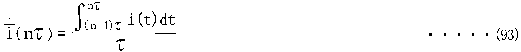


- The control apparatus (170; 270) according to any one of claims 1-7,
wherein the driving current (i(t)) supplied to the linear solenoid (SSLT; 234a) is controlled by an input voltage (vin(t)) that is obtained by causing a battery voltage (Pb) to be subjected to an ON-OFF control based on a PWM signal,
wherein a resistance Rz[Ω] of an electric circuit of the linear solenoid (SSLT; 234a), through which the driving current (i(t)) flows, is calculated in accordance with equation (96), and an inductance L[H] of the electric circuit is calculated in accordance with equation (97), where "τ[s]" represents each driving period of the PWM signal, "τ1[s]" represents an ON time that is a length of time for which the driving current (i(t)) is supplied to the linear solenoid (SSLT; 234a) in each driving period, "τ2[s]" represents an OFF time that is a length of time for which the driving current (i(t)) is not supplied to the linear solenoid (SSLT; 234a) in each driving period, "Pb[V]" represents the battery voltage (Pb), "Iavec[A]" represents an average value of the driving current (i(t)) in a converged state, and "Iminc[A]" represents a minimum instantaneous current value of the driving current (i(t)) in the converged state, and
wherein the parameters (K, ∑) are corrected depending on the resistance Rz[Ω] and the inductance L[H] that are calculated in accordance with the respective equations (96) and (97).

- The control apparatus (170; 270) according to any one of claims 1-5,
wherein the driving current (i(t)) supplied to the linear solenoid (SSLT; 234a) is controlled by an input voltage (vin(t)) that is obtained by causing a battery voltage (Pb) to be subjected to an ON-OFF control based on a PWM signal,
the control apparatus (170; 270) comprises:an electric circuit approximating portion (190a) configured to approximate an electric circuit of the linear solenoid (SSLT; 234a), through which the driving current (i(t)) flows, by a series circuit of a resistance (Rz) and an inductance (Ls);a first formulating portion (190b) configured to formulate a circuit equation related to an instantaneous value of the driving current (i(t)) flowing through the series circuit;a second formulating portion (190c) configured to formulate an equation related to a controlled variable (i(nτ)) for controlling the driving current (i(t));a recurrence-equation deriving portion (190d) configured to derive a recurrence equation from the equation related to the controlled variable (i(nτ));a recurrence-equation solving portion (190e) configured to solve the recurrence equation;a linearizing portion (190f) configured to linearize the solved recurrence equation is linearized by an approximation equation; anda transfer-function deriving portion (190g) configured to derive, from the linearized equation related to the controlled variable (i(nτ)), a transfer function (G(s)) of the feedback control, which is to be used to determine the controlled variable (i(nτ)).
Applications Claiming Priority (1)
| Application Number | Priority Date | Filing Date | Title |
|---|---|---|---|
| JP2018131133A JP7159657B2 (en) | 2018-07-10 | 2018-07-10 | linear solenoid controller |
Publications (2)
| Publication Number | Publication Date |
|---|---|
| EP3627005A1 true EP3627005A1 (en) | 2020-03-25 |
| EP3627005B1 EP3627005B1 (en) | 2021-08-25 |
Family
ID=67226106
Family Applications (1)
| Application Number | Title | Priority Date | Filing Date |
|---|---|---|---|
| EP19185417.3A Active EP3627005B1 (en) | 2018-07-10 | 2019-07-10 | Control apparatus for linear solenoid |
Country Status (7)
| Country | Link |
|---|---|
| US (1) | US11237575B2 (en) |
| EP (1) | EP3627005B1 (en) |
| JP (1) | JP7159657B2 (en) |
| KR (1) | KR102142842B1 (en) |
| CN (1) | CN110701296B (en) |
| BR (1) | BR102019013501A2 (en) |
| RU (1) | RU2719336C1 (en) |
Families Citing this family (4)
| Publication number | Priority date | Publication date | Assignee | Title |
|---|---|---|---|---|
| US11726757B2 (en) * | 2019-08-14 | 2023-08-15 | Nvidia Corporation | Processor for performing dynamic programming according to an instruction, and a method for configuring a processor for dynamic programming via an instruction |
| CN112196991B (en) * | 2020-09-30 | 2021-08-06 | 安徽江淮汽车集团股份有限公司 | Electromagnet gear shifting actuator current detection method, device, storage medium and device |
| JP7468324B2 (en) | 2020-12-08 | 2024-04-16 | トヨタ自動車株式会社 | Linear solenoid valve control device |
| CN113063024B (en) * | 2021-03-22 | 2022-06-14 | 南昌智能新能源汽车研究院 | Closed-loop control method of electromagnetic valve pressure and controller design method thereof |
Citations (8)
| Publication number | Priority date | Publication date | Assignee | Title |
|---|---|---|---|---|
| US5479803A (en) * | 1992-06-19 | 1996-01-02 | Kabushiki Kaisha Toshiba | Control apparatus for a continuous hot rolling mill |
| JP2003067006A (en) | 2001-08-29 | 2003-03-07 | Denso Corp | On-vehicle controller |
| JP2004212182A (en) | 2002-12-27 | 2004-07-29 | Aisin Aw Co Ltd | Inspection system for power train, power train inspected by the inspection system, and controller for the power train |
| JP2009014118A (en) | 2007-07-05 | 2009-01-22 | Mitsubishi Electric Corp | Control device for transmission |
| US20090183677A1 (en) * | 2008-01-22 | 2009-07-23 | Tokyo Electron Limited | Temperature control device and processing apparatus using the same |
| US20100163360A1 (en) * | 2008-12-25 | 2010-07-01 | Aisin Aw Co., Ltd. | Solenoid valve |
| US20110029220A1 (en) * | 2009-07-31 | 2011-02-03 | Transtron Inc. | Intake system control device and method |
| US20120138415A1 (en) * | 2009-08-21 | 2012-06-07 | Honda Motor Co., Ltd. | Hydraulic control device |
Family Cites Families (20)
| Publication number | Priority date | Publication date | Assignee | Title |
|---|---|---|---|---|
| US4724939A (en) * | 1986-07-17 | 1988-02-16 | General Motors Corporation | Closed loop clutch slip control system with turbine roughness control |
| JP2594060B2 (en) * | 1987-09-05 | 1997-03-26 | 株式会社堀場製作所 | Decoupling control system for engine bench test equipment. |
| JP3208869B2 (en) * | 1992-10-20 | 2001-09-17 | 株式会社デンソー | Closed loop correction device for air-fuel ratio control value |
| JP3293283B2 (en) * | 1993-11-26 | 2002-06-17 | 隆雄 藤井 | Hydraulic drive type speaker |
| JP3399062B2 (en) * | 1993-12-22 | 2003-04-21 | トヨタ自動車株式会社 | Failure detection device for automatic transmission for vehicles |
| JP3267836B2 (en) | 1995-06-05 | 2002-03-25 | トヨタ自動車株式会社 | Control device and its design method, and clutch slip control device and its design method |
| GB2337090A (en) * | 1998-05-08 | 1999-11-10 | Torotrak Dev Ltd | Hydraulic control circuit for a continuously-variable ratio transmission |
| JP3591422B2 (en) * | 1999-08-25 | 2004-11-17 | 住友金属工業株式会社 | Level control method and level control device for continuous casting machine |
| US6565064B2 (en) * | 2001-03-21 | 2003-05-20 | Delphi Technologies, Inc. | Model-based position control for a solenoid actuated valve |
| US20090222179A1 (en) * | 2008-03-03 | 2009-09-03 | Quan Zheng | Dynamic learning of solenoid p-i curves for closed loop pressure controls |
| JP4858600B2 (en) * | 2009-11-20 | 2012-01-18 | トヨタ自動車株式会社 | Control device for steering transmission ratio variable device |
| JP5333324B2 (en) * | 2010-04-06 | 2013-11-06 | トヨタ自動車株式会社 | Hydraulic control device for vehicle |
| JP5430535B2 (en) | 2010-10-25 | 2014-03-05 | 本田技研工業株式会社 | Plant control equipment |
| JP5149974B2 (en) * | 2011-02-17 | 2013-02-20 | アイシン・エィ・ダブリュ株式会社 | Vehicle drive device |
| JP5590428B2 (en) * | 2011-03-25 | 2014-09-17 | アイシン・エィ・ダブリュ株式会社 | Control device |
| JP5496259B2 (en) * | 2012-06-12 | 2014-05-21 | 三菱電機株式会社 | Transmission control device and output characteristic adjustment method of transmission control device |
| JP6465432B2 (en) * | 2014-12-26 | 2019-02-06 | 太平洋マテリアル株式会社 | High strength shotcrete |
| JP2017174218A (en) * | 2016-03-24 | 2017-09-28 | 株式会社豊田自動織機 | Current control device |
| KR101918532B1 (en) | 2016-12-28 | 2018-11-15 | 주식회사 유니크 | Solenoid valve |
| JP7154899B2 (en) | 2018-09-07 | 2022-10-18 | 三菱重工機械システム株式会社 | Vehicle protection system for mechanical parking device, vehicle protection method thereof, vehicle protection program, and mechanical parking device |
-
2018
- 2018-07-10 JP JP2018131133A patent/JP7159657B2/en active Active
-
2019
- 2019-06-28 BR BR102019013501A patent/BR102019013501A2/en not_active Application Discontinuation
- 2019-07-03 RU RU2019120691A patent/RU2719336C1/en active
- 2019-07-05 KR KR1020190081505A patent/KR102142842B1/en active IP Right Grant
- 2019-07-08 CN CN201910610688.8A patent/CN110701296B/en active Active
- 2019-07-09 US US16/506,036 patent/US11237575B2/en active Active
- 2019-07-10 EP EP19185417.3A patent/EP3627005B1/en active Active
Patent Citations (8)
| Publication number | Priority date | Publication date | Assignee | Title |
|---|---|---|---|---|
| US5479803A (en) * | 1992-06-19 | 1996-01-02 | Kabushiki Kaisha Toshiba | Control apparatus for a continuous hot rolling mill |
| JP2003067006A (en) | 2001-08-29 | 2003-03-07 | Denso Corp | On-vehicle controller |
| JP2004212182A (en) | 2002-12-27 | 2004-07-29 | Aisin Aw Co Ltd | Inspection system for power train, power train inspected by the inspection system, and controller for the power train |
| JP2009014118A (en) | 2007-07-05 | 2009-01-22 | Mitsubishi Electric Corp | Control device for transmission |
| US20090183677A1 (en) * | 2008-01-22 | 2009-07-23 | Tokyo Electron Limited | Temperature control device and processing apparatus using the same |
| US20100163360A1 (en) * | 2008-12-25 | 2010-07-01 | Aisin Aw Co., Ltd. | Solenoid valve |
| US20110029220A1 (en) * | 2009-07-31 | 2011-02-03 | Transtron Inc. | Intake system control device and method |
| US20120138415A1 (en) * | 2009-08-21 | 2012-06-07 | Honda Motor Co., Ltd. | Hydraulic control device |
Non-Patent Citations (1)
| Title |
|---|
| HIDENORI KIMURATAKAO FUJIITAKEHIRO MORI: "Robust Control", 1994, KORONA-SHA, pages: 141 - 153 |
Also Published As
| Publication number | Publication date |
|---|---|
| KR102142842B1 (en) | 2020-08-10 |
| US20200019196A1 (en) | 2020-01-16 |
| RU2719336C1 (en) | 2020-04-17 |
| CN110701296A (en) | 2020-01-17 |
| CN110701296B (en) | 2021-02-05 |
| BR102019013501A2 (en) | 2020-02-04 |
| KR20200006496A (en) | 2020-01-20 |
| JP2020009275A (en) | 2020-01-16 |
| EP3627005B1 (en) | 2021-08-25 |
| JP7159657B2 (en) | 2022-10-25 |
| US11237575B2 (en) | 2022-02-01 |
Similar Documents
| Publication | Publication Date | Title |
|---|---|---|
| EP3627005B1 (en) | Control apparatus for linear solenoid | |
| US7212898B2 (en) | Method and apparatus for adaptive control of power-on skip through neutral downshifts | |
| US6813551B2 (en) | Control apparatus for continuously variable transmission | |
| US8831843B2 (en) | Hydraulic pressure controller | |
| US20060089775A1 (en) | Method and apparatus for adaptive control of power-on downshifts in an automatic transmission | |
| JP2672063B2 (en) | Control device for automatic transmission | |
| Meng et al. | Smooth shift control of an automatic transmission for heavy-duty vehicles | |
| Liu et al. | Robust clutch slip controller design for automatic transmission | |
| US20160017995A1 (en) | Control device for automatic transmission | |
| EP2105634A2 (en) | Automatic transmission controller and automatic transmission control method | |
| EP0800124B1 (en) | Fuzzy logic adaptive shift control | |
| US20050096823A1 (en) | Auxiliary gearset shift progression command generator for a swap-shift automatic transmission | |
| US9683656B2 (en) | Diagnostics for clutch torque estimation | |
| US6962552B2 (en) | Vehicle shift control device and control method therefor | |
| Watechagit | Modeling and estimation for stepped automatic transmission with clutch-to-clutch shift technology | |
| US6428440B2 (en) | Apparatus and a method for controlling an automatic transmission | |
| US9933069B2 (en) | Dynamic compensation for clutch control during shift | |
| US6262556B1 (en) | Force motor current control for an electronically controlled automatic transmission | |
| JP3395561B2 (en) | Transmission control device for automatic transmission | |
| US11414081B1 (en) | Predictive-based control for transmission shifting | |
| JP3816710B2 (en) | Control device for automatic transmission | |
| Mishra et al. | Robust nonlinear estimation and control of clutch-to-clutch shifts | |
| JPH1122814A (en) | Gear shift transient control device for automatic transmission | |
| JP2927534B2 (en) | Hydraulic control device for automatic transmission | |
| JP6830189B2 (en) | Control method of continuously variable transmission and continuously variable transmission |
Legal Events
| Date | Code | Title | Description |
|---|---|---|---|
| PUAI | Public reference made under article 153(3) epc to a published international application that has entered the european phase |
Free format text: ORIGINAL CODE: 0009012 |
|
| STAA | Information on the status of an ep patent application or granted ep patent |
Free format text: STATUS: REQUEST FOR EXAMINATION WAS MADE |
|
| 17P | Request for examination filed |
Effective date: 20190710 |
|
| AK | Designated contracting states |
Kind code of ref document: A1 Designated state(s): AL AT BE BG CH CY CZ DE DK EE ES FI FR GB GR HR HU IE IS IT LI LT LU LV MC MK MT NL NO PL PT RO RS SE SI SK SM TR |
|
| AX | Request for extension of the european patent |
Extension state: BA ME |
|
| STAA | Information on the status of an ep patent application or granted ep patent |
Free format text: STATUS: EXAMINATION IS IN PROGRESS |
|
| 17Q | First examination report despatched |
Effective date: 20201015 |
|
| STAA | Information on the status of an ep patent application or granted ep patent |
Free format text: STATUS: EXAMINATION IS IN PROGRESS |
|
| GRAP | Despatch of communication of intention to grant a patent |
Free format text: ORIGINAL CODE: EPIDOSNIGR1 |
|
| STAA | Information on the status of an ep patent application or granted ep patent |
Free format text: STATUS: GRANT OF PATENT IS INTENDED |
|
| INTG | Intention to grant announced |
Effective date: 20210311 |
|
| GRAS | Grant fee paid |
Free format text: ORIGINAL CODE: EPIDOSNIGR3 |
|
| GRAA | (expected) grant |
Free format text: ORIGINAL CODE: 0009210 |
|
| STAA | Information on the status of an ep patent application or granted ep patent |
Free format text: STATUS: THE PATENT HAS BEEN GRANTED |
|
| AK | Designated contracting states |
Kind code of ref document: B1 Designated state(s): AL AT BE BG CH CY CZ DE DK EE ES FI FR GB GR HR HU IE IS IT LI LT LU LV MC MK MT NL NO PL PT RO RS SE SI SK SM TR |
|
| REG | Reference to a national code |
Ref country code: CH Ref legal event code: EP |
|
| REG | Reference to a national code |
Ref country code: DE Ref legal event code: R096 Ref document number: 602019007104 Country of ref document: DE |
|
| REG | Reference to a national code |
Ref country code: IE Ref legal event code: FG4D Ref country code: AT Ref legal event code: REF Ref document number: 1424119 Country of ref document: AT Kind code of ref document: T Effective date: 20210915 |
|
| REG | Reference to a national code |
Ref country code: LT Ref legal event code: MG9D |
|
| REG | Reference to a national code |
Ref country code: NL Ref legal event code: MP Effective date: 20210825 |
|
| REG | Reference to a national code |
Ref country code: AT Ref legal event code: MK05 Ref document number: 1424119 Country of ref document: AT Kind code of ref document: T Effective date: 20210825 |
|
| PG25 | Lapsed in a contracting state [announced via postgrant information from national office to epo] |
Ref country code: LT Free format text: LAPSE BECAUSE OF FAILURE TO SUBMIT A TRANSLATION OF THE DESCRIPTION OR TO PAY THE FEE WITHIN THE PRESCRIBED TIME-LIMIT Effective date: 20210825 Ref country code: AT Free format text: LAPSE BECAUSE OF FAILURE TO SUBMIT A TRANSLATION OF THE DESCRIPTION OR TO PAY THE FEE WITHIN THE PRESCRIBED TIME-LIMIT Effective date: 20210825 Ref country code: BG Free format text: LAPSE BECAUSE OF FAILURE TO SUBMIT A TRANSLATION OF THE DESCRIPTION OR TO PAY THE FEE WITHIN THE PRESCRIBED TIME-LIMIT Effective date: 20211125 Ref country code: HR Free format text: LAPSE BECAUSE OF FAILURE TO SUBMIT A TRANSLATION OF THE DESCRIPTION OR TO PAY THE FEE WITHIN THE PRESCRIBED TIME-LIMIT Effective date: 20210825 Ref country code: NO Free format text: LAPSE BECAUSE OF FAILURE TO SUBMIT A TRANSLATION OF THE DESCRIPTION OR TO PAY THE FEE WITHIN THE PRESCRIBED TIME-LIMIT Effective date: 20211125 Ref country code: PT Free format text: LAPSE BECAUSE OF FAILURE TO SUBMIT A TRANSLATION OF THE DESCRIPTION OR TO PAY THE FEE WITHIN THE PRESCRIBED TIME-LIMIT Effective date: 20211227 Ref country code: SE Free format text: LAPSE BECAUSE OF FAILURE TO SUBMIT A TRANSLATION OF THE DESCRIPTION OR TO PAY THE FEE WITHIN THE PRESCRIBED TIME-LIMIT Effective date: 20210825 Ref country code: RS Free format text: LAPSE BECAUSE OF FAILURE TO SUBMIT A TRANSLATION OF THE DESCRIPTION OR TO PAY THE FEE WITHIN THE PRESCRIBED TIME-LIMIT Effective date: 20210825 Ref country code: ES Free format text: LAPSE BECAUSE OF FAILURE TO SUBMIT A TRANSLATION OF THE DESCRIPTION OR TO PAY THE FEE WITHIN THE PRESCRIBED TIME-LIMIT Effective date: 20210825 Ref country code: FI Free format text: LAPSE BECAUSE OF FAILURE TO SUBMIT A TRANSLATION OF THE DESCRIPTION OR TO PAY THE FEE WITHIN THE PRESCRIBED TIME-LIMIT Effective date: 20210825 |
|
| PG25 | Lapsed in a contracting state [announced via postgrant information from national office to epo] |
Ref country code: PL Free format text: LAPSE BECAUSE OF FAILURE TO SUBMIT A TRANSLATION OF THE DESCRIPTION OR TO PAY THE FEE WITHIN THE PRESCRIBED TIME-LIMIT Effective date: 20210825 Ref country code: LV Free format text: LAPSE BECAUSE OF FAILURE TO SUBMIT A TRANSLATION OF THE DESCRIPTION OR TO PAY THE FEE WITHIN THE PRESCRIBED TIME-LIMIT Effective date: 20210825 Ref country code: GR Free format text: LAPSE BECAUSE OF FAILURE TO SUBMIT A TRANSLATION OF THE DESCRIPTION OR TO PAY THE FEE WITHIN THE PRESCRIBED TIME-LIMIT Effective date: 20211126 |
|
| PG25 | Lapsed in a contracting state [announced via postgrant information from national office to epo] |
Ref country code: NL Free format text: LAPSE BECAUSE OF FAILURE TO SUBMIT A TRANSLATION OF THE DESCRIPTION OR TO PAY THE FEE WITHIN THE PRESCRIBED TIME-LIMIT Effective date: 20210825 |
|
| PG25 | Lapsed in a contracting state [announced via postgrant information from national office to epo] |
Ref country code: DK Free format text: LAPSE BECAUSE OF FAILURE TO SUBMIT A TRANSLATION OF THE DESCRIPTION OR TO PAY THE FEE WITHIN THE PRESCRIBED TIME-LIMIT Effective date: 20210825 |
|
| REG | Reference to a national code |
Ref country code: DE Ref legal event code: R097 Ref document number: 602019007104 Country of ref document: DE |
|
| PG25 | Lapsed in a contracting state [announced via postgrant information from national office to epo] |
Ref country code: SM Free format text: LAPSE BECAUSE OF FAILURE TO SUBMIT A TRANSLATION OF THE DESCRIPTION OR TO PAY THE FEE WITHIN THE PRESCRIBED TIME-LIMIT Effective date: 20210825 Ref country code: SK Free format text: LAPSE BECAUSE OF FAILURE TO SUBMIT A TRANSLATION OF THE DESCRIPTION OR TO PAY THE FEE WITHIN THE PRESCRIBED TIME-LIMIT Effective date: 20210825 Ref country code: RO Free format text: LAPSE BECAUSE OF FAILURE TO SUBMIT A TRANSLATION OF THE DESCRIPTION OR TO PAY THE FEE WITHIN THE PRESCRIBED TIME-LIMIT Effective date: 20210825 Ref country code: EE Free format text: LAPSE BECAUSE OF FAILURE TO SUBMIT A TRANSLATION OF THE DESCRIPTION OR TO PAY THE FEE WITHIN THE PRESCRIBED TIME-LIMIT Effective date: 20210825 Ref country code: CZ Free format text: LAPSE BECAUSE OF FAILURE TO SUBMIT A TRANSLATION OF THE DESCRIPTION OR TO PAY THE FEE WITHIN THE PRESCRIBED TIME-LIMIT Effective date: 20210825 Ref country code: AL Free format text: LAPSE BECAUSE OF FAILURE TO SUBMIT A TRANSLATION OF THE DESCRIPTION OR TO PAY THE FEE WITHIN THE PRESCRIBED TIME-LIMIT Effective date: 20210825 |
|
| PLBE | No opposition filed within time limit |
Free format text: ORIGINAL CODE: 0009261 |
|
| STAA | Information on the status of an ep patent application or granted ep patent |
Free format text: STATUS: NO OPPOSITION FILED WITHIN TIME LIMIT |
|
| PG25 | Lapsed in a contracting state [announced via postgrant information from national office to epo] |
Ref country code: IT Free format text: LAPSE BECAUSE OF FAILURE TO SUBMIT A TRANSLATION OF THE DESCRIPTION OR TO PAY THE FEE WITHIN THE PRESCRIBED TIME-LIMIT Effective date: 20210825 |
|
| PGFP | Annual fee paid to national office [announced via postgrant information from national office to epo] |
Ref country code: FR Payment date: 20220510 Year of fee payment: 4 |
|
| 26N | No opposition filed |
Effective date: 20220527 |
|
| PG25 | Lapsed in a contracting state [announced via postgrant information from national office to epo] |
Ref country code: SI Free format text: LAPSE BECAUSE OF FAILURE TO SUBMIT A TRANSLATION OF THE DESCRIPTION OR TO PAY THE FEE WITHIN THE PRESCRIBED TIME-LIMIT Effective date: 20210825 |
|
| PGFP | Annual fee paid to national office [announced via postgrant information from national office to epo] |
Ref country code: DE Payment date: 20220517 Year of fee payment: 4 |
|
| PG25 | Lapsed in a contracting state [announced via postgrant information from national office to epo] |
Ref country code: MC Free format text: LAPSE BECAUSE OF FAILURE TO SUBMIT A TRANSLATION OF THE DESCRIPTION OR TO PAY THE FEE WITHIN THE PRESCRIBED TIME-LIMIT Effective date: 20210825 |
|
| REG | Reference to a national code |
Ref country code: CH Ref legal event code: PL |
|
| REG | Reference to a national code |
Ref country code: BE Ref legal event code: MM Effective date: 20220731 |
|
| PG25 | Lapsed in a contracting state [announced via postgrant information from national office to epo] |
Ref country code: LU Free format text: LAPSE BECAUSE OF NON-PAYMENT OF DUE FEES Effective date: 20220710 Ref country code: LI Free format text: LAPSE BECAUSE OF NON-PAYMENT OF DUE FEES Effective date: 20220731 Ref country code: CH Free format text: LAPSE BECAUSE OF NON-PAYMENT OF DUE FEES Effective date: 20220731 |
|
| PG25 | Lapsed in a contracting state [announced via postgrant information from national office to epo] |
Ref country code: BE Free format text: LAPSE BECAUSE OF NON-PAYMENT OF DUE FEES Effective date: 20220731 |
|
| P01 | Opt-out of the competence of the unified patent court (upc) registered |
Effective date: 20230427 |
|
| PG25 | Lapsed in a contracting state [announced via postgrant information from national office to epo] |
Ref country code: IE Free format text: LAPSE BECAUSE OF NON-PAYMENT OF DUE FEES Effective date: 20220710 |
|
| REG | Reference to a national code |
Ref country code: DE Ref legal event code: R119 Ref document number: 602019007104 Country of ref document: DE |
|
| GBPC | Gb: european patent ceased through non-payment of renewal fee |
Effective date: 20230710 |
|
| PG25 | Lapsed in a contracting state [announced via postgrant information from national office to epo] |
Ref country code: HU Free format text: LAPSE BECAUSE OF FAILURE TO SUBMIT A TRANSLATION OF THE DESCRIPTION OR TO PAY THE FEE WITHIN THE PRESCRIBED TIME-LIMIT; INVALID AB INITIO Effective date: 20190710 |