EP3626982B1 - Self-piercing rivet - Google Patents
Self-piercing rivet Download PDFInfo
- Publication number
- EP3626982B1 EP3626982B1 EP18195850.5A EP18195850A EP3626982B1 EP 3626982 B1 EP3626982 B1 EP 3626982B1 EP 18195850 A EP18195850 A EP 18195850A EP 3626982 B1 EP3626982 B1 EP 3626982B1
- Authority
- EP
- European Patent Office
- Prior art keywords
- shank
- rivet
- self
- piercing
- radius
- Prior art date
- Legal status (The legal status is an assumption and is not a legal conclusion. Google has not performed a legal analysis and makes no representation as to the accuracy of the status listed.)
- Active
Links
- 239000000463 material Substances 0.000 claims description 32
- 238000005304 joining Methods 0.000 claims description 16
- 230000007704 transition Effects 0.000 claims description 12
- 229910052782 aluminium Inorganic materials 0.000 description 11
- XAGFODPZIPBFFR-UHFFFAOYSA-N aluminium Chemical compound [Al] XAGFODPZIPBFFR-UHFFFAOYSA-N 0.000 description 11
- 238000004519 manufacturing process Methods 0.000 description 9
- 239000004411 aluminium Substances 0.000 description 8
- 238000000034 method Methods 0.000 description 5
- 229910000838 Al alloy Inorganic materials 0.000 description 4
- 229910000831 Steel Inorganic materials 0.000 description 4
- 239000010959 steel Substances 0.000 description 4
- FYYHWMGAXLPEAU-UHFFFAOYSA-N Magnesium Chemical compound [Mg] FYYHWMGAXLPEAU-UHFFFAOYSA-N 0.000 description 3
- 239000003562 lightweight material Substances 0.000 description 3
- 239000011777 magnesium Substances 0.000 description 3
- 230000035515 penetration Effects 0.000 description 3
- 239000004918 carbon fiber reinforced polymer Substances 0.000 description 2
- 229910052749 magnesium Inorganic materials 0.000 description 2
- 229910001092 metal group alloy Inorganic materials 0.000 description 2
- 239000004033 plastic Substances 0.000 description 2
- 229920003023 plastic Polymers 0.000 description 2
- 238000004080 punching Methods 0.000 description 2
- 239000007787 solid Substances 0.000 description 2
- 229910000861 Mg alloy Inorganic materials 0.000 description 1
- 230000001154 acute effect Effects 0.000 description 1
- 239000011248 coating agent Substances 0.000 description 1
- 238000000576 coating method Methods 0.000 description 1
- 230000000052 comparative effect Effects 0.000 description 1
- 238000010276 construction Methods 0.000 description 1
- 238000005520 cutting process Methods 0.000 description 1
- 238000005553 drilling Methods 0.000 description 1
- 239000000428 dust Substances 0.000 description 1
- 238000005265 energy consumption Methods 0.000 description 1
- 238000005516 engineering process Methods 0.000 description 1
- 238000003780 insertion Methods 0.000 description 1
- 230000037431 insertion Effects 0.000 description 1
- 239000000314 lubricant Substances 0.000 description 1
- 238000002844 melting Methods 0.000 description 1
- 230000008018 melting Effects 0.000 description 1
- 230000000007 visual effect Effects 0.000 description 1
- 239000013585 weight reducing agent Substances 0.000 description 1
Images

Classifications
-
- F—MECHANICAL ENGINEERING; LIGHTING; HEATING; WEAPONS; BLASTING
- F16—ENGINEERING ELEMENTS AND UNITS; GENERAL MEASURES FOR PRODUCING AND MAINTAINING EFFECTIVE FUNCTIONING OF MACHINES OR INSTALLATIONS; THERMAL INSULATION IN GENERAL
- F16B—DEVICES FOR FASTENING OR SECURING CONSTRUCTIONAL ELEMENTS OR MACHINE PARTS TOGETHER, e.g. NAILS, BOLTS, CIRCLIPS, CLAMPS, CLIPS OR WEDGES; JOINTS OR JOINTING
- F16B19/00—Bolts without screw-thread; Pins, including deformable elements; Rivets
- F16B19/04—Rivets; Spigots or the like fastened by riveting
- F16B19/08—Hollow rivets; Multi-part rivets
- F16B19/086—Self-piercing rivets
Definitions
- the present disclosure relates to a self-piercing rivet, in particular a semi-hollow self-piercing rivet, for the production of a joining connection between at least two components, and notably between three components.
- the self-piercing rivet is used in particular to produce a joining connection between components or layers made of light-weight materials.
- a self-piercing rivet is partially hollow with a head and a cylindrical shank that terminates in an annular edge. As the rivet is driven into at least two overlapping sheets of material over a suitably shaped die, the shank is caused to flare outwardly. The sheets of material are caused to deform around the shank, creating an annulus that encapsulates the shank. The shank and edge of the rivet remain embedded in the sheet material after the rivet has been set. Self-piercing riveting enables sheet material to be joined without the requirement for the pre-drilling or pre-punching of a hole in the material.
- the punch riveting as a joining method is widely used in the industry. Especially in the manufacturing of automobiles where light-weight materials, such as aluminium or high-strength steel, magnesium sheets, plastic, carbon fiber reinforced plastic and similar materials, have been adopted for vehicle body panels in the interests of weight reduction and therefore reduced energy consumption. Aluminium is notably difficult or not feasible to spot weld, particularly to steel, owing to its high thermal conductivity, low melting range and propensity to form oxide surface film. Therefore, always new demands are being placed on punch-rivet connections.
- EP1387093 discloses a self-piercing rivet adapted to obtain sufficient undercut for the fixation of the rivet in the workpiece.
- DE102015101950 is directed to a self-piercing rivet for high-strength workpieces having an angled shank end face.
- WO2014013232 discloses a method for forming a joint in a stack of at least two sheets of light metal alloy, using a self- piercing rivet that is fully hollow.
- the rivet is coated at least along a portion of its bore by a lubricant and pierces the upper surface thereof and such that the shank deforms outwardly to interlock with the material but without penetration to the die side of the material.
- the outside diameter of the shank of the rivet is 5.4mm or less.
- the die has a volume that is less than 60% or 70% of the effective solid volume of the rivet.
- US9316243 describes a self-piercing rivet comprising a head and a substantially cylindrical shank that is at least partially hollow so as to define a bore that extends along at least part of its length, wherein the outside diameter of the shank is at least 6 mm, the effective length of the rivet is at least 1.3 times the diameter of the shank and the bore has a volume that is at least 38% of the effective solid volume of the rivet.
- Such rivet is suitable for use with thick stack, high strength light metal alloys such as magnesium and aluminium alloys.
- US2017009794 is directed to a self-piercing rivet, in particular a semi-hollow self-piercing rivet, for the production of a joining connection between at least two components, in particular for the production of a joining connection between a component made of high-strength steel and a component made of a thick-walled aluminum sheet or cast aluminum, as well as a method therefor.
- the self-piercing rivet comprises a rivet head and a rivet shank having a central shank bore, wherein the rivet head has an upper side having a predetermined head diameter.
- the rivet shank comprises a cylindrical shank outer surface and a shank inner surface limiting the central shank bore.
- the shank outer surface and the shank inner surface are connected at the axial end of the rivet shank facing away from the rivet head by a flat shank end face and a shank end radius, and the shank end radius transitions tangentially into the shank inner surface, is at least twice as great as the maximum radial width of the rivet shank.
- the plane shank end face is connected to the shank outer surface by a cutting edge, and a ratio of maximum radial width of the rivet shank to the radial shank end surface width is in the range of 1.5 to 2.5. Due to the specific geometry of the rivet shank, the self-piercing rivet is given sufficient axial stability for punching through a high-strength top layer. At the same time, the construction of the rivet base provides a sufficiently blunt geometry to penetrate the high-strength top layer with a sufficiently sharp or acute geometry for entering a softer further material layer compared to the high-strength top layer.
- the self-piercing rivet for producing a joining connection between at least two or three components comprises a rivet head and a rivet shank.
- the rivet shank has a central bore comprising a base, a cylindrical shank outer surface and a shank inner surface limiting the central shank bore.
- An annular piercing end is provided on the rivet shank away from the rivet head.
- the shank outer surface has a first diameter, the shank bore comprises a bore depth between the base of the central shank bore and the annular piercing end. The ratio of the first diameter to the bore depth is in the range of 0.50 to 0.67.
- the formed self-piercing rivet is characterized by its special geometry of its rivet shank which allows a lower insertion force and a lower die volume. It was known from the state of the art to manufacture self-piercing rivets with geometries complying with special bore depth or rivet length, or special ratios between the rivet length and the rivet diameter. However, several tests have surprisingly shown that a self-piercing rivet geometry having a ratio of the shank outer surface diameter to the bore depth between 0.5 and 0.67 allows to perform a rivet having good joining qualities, notably for brittle materials such as aluminium alloys and stack of three components. Such ratio is particularly advantageous, since it allows a reduction of the rivet volume. The rivet volume being reduced, the weight of the rivet is lower than usual.
- the reduction of the rivet volume leads to a reduction of the die volume.
- the lower die volume allows the connection of brittle materials which can be arranged on the die side for the joining connection.
- a ratio of the first diameter to the bore depth smaller than 0,5 does not provide adequate results since this would be a complete hollow rivet or a rivet with a very thin head thickness. If the rivet is completely hollow all the "dust" (e.g. coating material that is wiped of the rivet and the sheets during the setting process) would come out at the top of the joint which could causes problems in the later car production and due to visual requirements car manufacturers prefer a flat joint appearance. If the head thickness is very thin it cannot be produced in a robust way by a cold-forming process (indeed, the cold forming forces would be too high).
- the ratio of the first diameter Ds to the bore depth T is in the range of 0.58 ⁇ Ds/T ⁇ 0.67, and more particularly of 0.58 ⁇ Ds/T ⁇ 0.63. Tests performed by the inventors have established that such ratio provides an even better joining quality.
- the base is conical or frustroconical with an arcuate transition of radius R2 between the periphery of the base and the shank inner surface.
- the base can be rounded. The self-piercing rivet manufacturing is thus simplified.
- the radius R2 is between 0.35 and 0.4 mm. Such radius simplifies the manufacturing.
- the shank outer surface and the shank inner surface are connected at the annular piercing end by a shank end face and a shank end radius R3.
- the shank end radius is comprised between 1.2 and 1.4 mm.
- the shank end radius is of 1.3 mm.
- Such shank end radius allows a good penetration of the self-piercing rivet into the material and improve the material flow.
- a conical taper surface is arranged between the shank end radius and the shank end face, and wherein the conical taper surface has an inclusive angle of 90 degrees. A conical entrance is thus performed.
- the shank end face is arcuate, and wherein the arcuate shank end face comprises a radius of curvature between 0.15 and 0.3 mm.
- the shank end face is flat. A self-piercing rivet with a flat shank end face is more robust and does not collapse.
- the head has an upper portion and a transition region defined between the upper portion and the shank, the transition region having a radius of curvature in the range 2.1 to 2.3 mm, and in particular of 2.2 mm.
- the stress in the material is thus reduced.
- the feeding technology remains unchanged with regard to prior rivets.
- the transition region may have a radius of curvature in the range of 0.5 to 2.3 mm. A low radius of curvature allows to minimize the setting forces.
- the head has an upper surface opposite the base and the thickness between the base and the upper surface is comprised between 1.5 and 3.5 mm.
- the rivet head comprises an upper portion having a height h along a longitudinal axis between 0.2 mm and 0.6 mm, and in particular of 3 mm.
- the bore depth T is between 8 mm and 9 mm.
- the rivet shank extends along a longitudinal axis, and wherein the annular piercing end has a length along the longitudinal axis of less than 0.3 mm.
- the self-piercing rivet is suitable for forming a joining connection in a stack of three components.
- the self-piercing rivet is used in a system comprising a punch, a die and a stack of materials.
- the material facing the die can be a brittle material.
- the material may have an elongation smaller than 15% or in particular smaller than 12%.
- cast aluminium, aluminium sheets or profiles may be implemented.
- Other materials such as high-strength steel, magnesium sheets, plastic, carbon fiber reinforced plastic and similar materials can also be used.
- the volume of the die corresponds to 100% to 120% of the self-piercing rivet volume.
- Fig. 1 and Fig. 3 show a self-piercing rivet 10 comprising a rivet head 12 and a rivet shank 14 extending along a longitudinal axis.
- the self-piercing rivet 10 is suitable for producing a joining connection between at least two components, and notably between three components C1, C2, C3, such as aluminium components or sheets of aluminium, as shown on Fig. 4B .
- the rivet shank 14 comprises a central shank bore 16 having a base 17.
- the rivet shank 14 further comprises a cylindrical shank outer surface 18 and a shank inner surface 20 limiting the central shank bore.
- the shank outer surface has a first diameter Ds.
- the shank inner surface 20 has a second diameter Di.
- the rivet shank 14 further comprises an annular piercing end 22 facing away from the rivet head 12.
- the central shank bore comprises a bore depth T between the base of the central shank bore and the annular piercing end. More particularly the bore depth T is the greatest distance along the longitudinal axis between the base 17 and the annular piercing end 22. For instance, the bore depth T is the distance between the most upper point of the surface of the base (in other words the point of the base situated the nearest of the upper surface of the head) and the most lower point of the annular piercing end 22.
- the geometry of the self-piercing rivet is such that a ratio of the first diameter Ds to the bore depth T is in the range of 0.50 ⁇ Ds/T ⁇ 0.67. More particularly, the ratio can be in the range of 0.58 or 0,59 to 0.67 or to 0.66.
- the geometry of the rivet is defined through the ratio outside diameter bore depth and not through other parameters like the rivet length L.
- the rivet head 12 extends radially outward from the rivet shank 14.
- the rivet head 12 has an upper portion 24 and a transition region defined between the upper portion 24 and the rivet shank 14.
- the transition region has a radius of curvature R1 in the range 2.1 to 2.3 mm, and in particular of 2.2 mm.
- the upper portion 24 has an upper surface 26 opposite the base 17.
- the thickness tbu between the base 17 and the upper surface 26 is comprised between 1.5 and 3.5 mm.
- the upper portion 24 of the rivet head 12 has a height h along the longitudinal axis.
- the base 17 can be conical or frustroconical.
- the base can also be rounded.
- the base can be provided with an arcuate transition of radius R2 between the periphery of the base and the shank inner surface.
- the radius R2 is between 0.35 and 0.4 mm.
- the shank inner surface 20 extends parallel to the longitudinal axis from the base until the annular piercing end 22.
- the shank outer surface 18 and the shank inner surface 20 are connected at the annular piercing end by a shank end face 28 and a shank end radius R3, as illustrated in Fig. 2 and Fig. 3 .
- the shank end radius R3 is between 1.2 and 1.4 millimeters (mm).
- the shank end radius is of 1.3 mm.
- the shank end face can be a flat shank end face, as depicted on Fig. 3 , which is not covered by the claimsed invention.
- the flat shank end face has a width w along an axis perpendicular to the longitudinal axis.
- the shank end face in accordance with the claimed invention is an arcuate shank end face with a radius R4, as illustrated in Fig. 1 .
- the radius R4 is between 0.15 and 0.3 mm.
- a conical taper surface is arranged between the shank end radius R3 and the shank end face.
- the conical taper surface has an inclusive angle ⁇ of 90 degrees.
- the annular piercing end has a length Lap along the longitudinal axis of less than 0.3 mm.
- the self-piercing rivet has an arcuate shank end face with a radius of curvature R4.
- the self-piercing rivet according to the first embodiment has the following dimensions: Ds 5.3 mm Di 3.2 mm ⁇ 90 Deg. T 9 mm h 0.3 mm tbu 2 mm R1 2.20 mm R2 0.35 mm R3 1.25 mm R4 0.3 mm
- the self-piercing rivet according to the first embodiment has the following dimensions: Ds 5.3 mm Di 3.2 mm ⁇ 90 Deg. T 9 mm h 0.3 mm tbu 2 mm R1 2.2 mm R2 0.4 mm R3 1.3 mm R4 0.15-0.3 mm
- the self-piercing rivet according to the first embodiment has the following dimensions: Ds 5.3 mm Di 3.26 mm ⁇ 90 Deg. T 8.5 mm h 0.3 mm tbu 2.5 mm R1 2.2 mm R2 0.35 mm R3 1.25 mm R4 0.15 mm
- the self-piercing rivet has a flat shank end face.
- the self-piercing rivet according to the second embodiment has the following dimensions: Ds 5.3 Di 3.3 ⁇ 90 Deg. T 8.5 mm h 0.3 mm tbu 2.5 mm R1 2.2 mm R2 0.4 mm R3 1.3 mm w 0.3 mm
- the self-piercing rivet according to the second embodiment has the following dimensions: Ds 5.3 Di 3.3 ⁇ 90 Deg. T 8.5 mm h 0.3 mm tbu 3.5 mm R1 2.2 mm R2 0.4 mm R3 1.3 mm w 0.3 mm
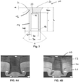
- FIG. 4A represents a joint formed in a stack of three sheets of brittle aluminium alloy by a self-piercing rivet.
- Fig. 4A represents a joint formed in a stack of three sheets of aluminium by a self-piercing rivet of the prior art.
- Fig. 4B represents a joint formed in a stack of three sheets of aluminium by a self-piercing rivet according to the present invention.
- the prior art self-piercing rivet has a first diameter to the bore depth ratio higher than 0.7.
- the joint section in fig. 4A reveals that such a structure with new relatively brittle aluminum alloys cannot be jointed with self-piercing riveting with rivets from the state of the art. Indeed, with such rivets, the remaining bottom sheet material thickness is too thin which causes cracks in a serial production environment. Additionally, the setting force is very high and exceeds the upper force tolerance of currently known und used self-piercing riveting equipment, and without this high force the interlock would be too small.
- Fig. 4B The self-piercing rivet of Fig. 4B is according to the present invention.
- Fig. 4B shows a well-performed joint.
- the remaining material thickness is significantly higher (no risks of cracks) and the setting forces are significantly lower. This allows reducing the die volume and thus reducing the deformation in the lower sheet material (also even less ductile materials can be jointed).
- the self-piercing rivet according to the invention allows the self-piercing riveting assembly range to be increased.
Description
- The present disclosure relates to a self-piercing rivet, in particular a semi-hollow self-piercing rivet, for the production of a joining connection between at least two components, and notably between three components. The self-piercing rivet is used in particular to produce a joining connection between components or layers made of light-weight materials.
- A self-piercing rivet is partially hollow with a head and a cylindrical shank that terminates in an annular edge. As the rivet is driven into at least two overlapping sheets of material over a suitably shaped die, the shank is caused to flare outwardly. The sheets of material are caused to deform around the shank, creating an annulus that encapsulates the shank. The shank and edge of the rivet remain embedded in the sheet material after the rivet has been set. Self-piercing riveting enables sheet material to be joined without the requirement for the pre-drilling or pre-punching of a hole in the material.
- The punch riveting as a joining method is widely used in the industry. Especially in the manufacturing of automobiles where light-weight materials, such as aluminium or high-strength steel, magnesium sheets, plastic, carbon fiber reinforced plastic and similar materials, have been adopted for vehicle body panels in the interests of weight reduction and therefore reduced energy consumption. Aluminium is notably difficult or not feasible to spot weld, particularly to steel, owing to its high thermal conductivity, low melting range and propensity to form oxide surface film. Therefore, always new demands are being placed on punch-rivet connections.
EP1387093 discloses a self-piercing rivet adapted to obtain sufficient undercut for the fixation of the rivet in the workpiece.DE102015101950 is directed to a self-piercing rivet for high-strength workpieces having an angled shank end face. - Numerous documents describe a self-piercing rivet particularly suitable for joining light-weight materials.
-
WO2014013232 discloses a method for forming a joint in a stack of at least two sheets of light metal alloy, using a self- piercing rivet that is fully hollow. The rivet is coated at least along a portion of its bore by a lubricant and pierces the upper surface thereof and such that the shank deforms outwardly to interlock with the material but without penetration to the die side of the material. The outside diameter of the shank of the rivet is 5.4mm or less. The die has a volume that is less than 60% or 70% of the effective solid volume of the rivet. -
US9316243 -
US2017009794 is directed to a self-piercing rivet, in particular a semi-hollow self-piercing rivet, for the production of a joining connection between at least two components, in particular for the production of a joining connection between a component made of high-strength steel and a component made of a thick-walled aluminum sheet or cast aluminum, as well as a method therefor. The self-piercing rivet comprises a rivet head and a rivet shank having a central shank bore, wherein the rivet head has an upper side having a predetermined head diameter. The rivet shank comprises a cylindrical shank outer surface and a shank inner surface limiting the central shank bore. The shank outer surface and the shank inner surface are connected at the axial end of the rivet shank facing away from the rivet head by a flat shank end face and a shank end radius, and the shank end radius transitions tangentially into the shank inner surface, is at least twice as great as the maximum radial width of the rivet shank. The plane shank end face is connected to the shank outer surface by a cutting edge, and a ratio of maximum radial width of the rivet shank to the radial shank end surface width is in the range of 1.5 to 2.5. Due to the specific geometry of the rivet shank, the self-piercing rivet is given sufficient axial stability for punching through a high-strength top layer. At the same time, the construction of the rivet base provides a sufficiently blunt geometry to penetrate the high-strength top layer with a sufficiently sharp or acute geometry for entering a softer further material layer compared to the high-strength top layer. - The above described geometries of self-piercing rivets are adapted to the joining connections in high-strength components or aluminum components. However, a need still exists to increase the joining quality and to develop a self-piercing rivet adapted to form a joining connection between new materials, and notably brittle materials or stack of more than two components. More particularly a brittle material shows a very low elongation because it does not (or very little) plastically deform. For instance, materials to be joined may present an elongation lower than 15% or even lower than 12%.
- The above-mentioned object is achieved by the self-piercing rivet defined in independent patent claim 1.
- The self-piercing rivet for producing a joining connection between at least two or three components comprises a rivet head and a rivet shank. The rivet shank has a central bore comprising a base, a cylindrical shank outer surface and a shank inner surface limiting the central shank bore. An annular piercing end is provided on the rivet shank away from the rivet head. The shank outer surface has a first diameter, the shank bore comprises a bore depth between the base of the central shank bore and the annular piercing end. The ratio of the first diameter to the bore depth is in the range of 0.50 to 0.67.
- The formed self-piercing rivet is characterized by its special geometry of its rivet shank which allows a lower insertion force and a lower die volume. It was known from the state of the art to manufacture self-piercing rivets with geometries complying with special bore depth or rivet length, or special ratios between the rivet length and the rivet diameter. However, several tests have surprisingly shown that a self-piercing rivet geometry having a ratio of the shank outer surface diameter to the bore depth between 0.5 and 0.67 allows to perform a rivet having good joining qualities, notably for brittle materials such as aluminium alloys and stack of three components. Such ratio is particularly advantageous, since it allows a reduction of the rivet volume. The rivet volume being reduced, the weight of the rivet is lower than usual. Besides, the reduction of the rivet volume leads to a reduction of the die volume. The lower die volume allows the connection of brittle materials which can be arranged on the die side for the joining connection. A ratio of the first diameter to the bore depth smaller than 0,5 does not provide adequate results since this would be a complete hollow rivet or a rivet with a very thin head thickness. If the rivet is completely hollow all the "dust" (e.g. coating material that is wiped of the rivet and the sheets during the setting process) would come out at the top of the joint which could causes problems in the later car production and due to visual requirements car manufacturers prefer a flat joint appearance. If the head thickness is very thin it cannot be produced in a robust way by a cold-forming process (indeed, the cold forming forces would be too high).
- In one embodiment, the ratio of the first diameter Ds to the bore depth T is in the range of 0.58≦Ds/T≦0.67, and more particularly of 0.58≦Ds/T≦0.63. Tests performed by the inventors have established that such ratio provides an even better joining quality.
- In one embodiment, the first diameter is of 5,3 mm. Self-piercing rivets with such diameters have a reduced weight and the force required to insert the rivet is low.
- In one embodiment, the base is conical or frustroconical with an arcuate transition of radius R2 between the periphery of the base and the shank inner surface. In another embodiment, the base can be rounded. The self-piercing rivet manufacturing is thus simplified.
- In one embodiment, the radius R2 is between 0.35 and 0.4 mm. Such radius simplifies the manufacturing.
- According to the invention, the shank outer surface and the shank inner surface are connected at the annular piercing end by a shank end face and a shank end radius R3.
- In one embodiment, the shank end radius is comprised between 1.2 and 1.4 mm. Notably, the shank end radius is of 1.3 mm. Such shank end radius allows a good penetration of the self-piercing rivet into the material and improve the material flow.
- In one embodiment, a conical taper surface is arranged between the shank end radius and the shank end face, and wherein the conical taper surface has an inclusive angle of 90 degrees. A conical entrance is thus performed.
- According to the invention, the shank end face is arcuate, and wherein the arcuate shank end face comprises a radius of curvature between 0.15 and 0.3 mm. Such arcuate shank end allows a good material penetration. In an example, which is not covered by the claimed invention, the shank end face is flat. A self-piercing rivet with a flat shank end face is more robust and does not collapse.
- In one embodiment, the head has an upper portion and a transition region defined between the upper portion and the shank, the transition region having a radius of curvature in the range 2.1 to 2.3 mm, and in particular of 2.2 mm. The stress in the material is thus reduced. Besides, the feeding technology remains unchanged with regard to prior rivets. In another embodiment, the transition region may have a radius of curvature in the range of 0.5 to 2.3 mm. A low radius of curvature allows to minimize the setting forces.
- In one embodiment, the head has an upper surface opposite the base and the thickness between the base and the upper surface is comprised between 1.5 and 3.5 mm. The smaller the radius of curvature in the transition region is, the greater the thickness tends to be. Besides, the rivet head comprises an upper portion having a height h along a longitudinal axis between 0.2 mm and 0.6 mm, and in particular of 3 mm.
- In one embodiment, the bore depth T is between 8 mm and 9 mm.
- In one embodiment, the rivet shank extends along a longitudinal axis, and wherein the annular piercing end has a length along the longitudinal axis of less than 0.3 mm.
- The self-piercing rivet is suitable for forming a joining connection in a stack of three components.
- The present invention is also directed to a self-piercing rivet joint with an upper workpiece and a lower workpiece, wherein the lower workpiece is formed from a brittle material, and with a self-piercing rivet as described above.
- The self-piercing rivet is used in a system comprising a punch, a die and a stack of materials. The material facing the die can be a brittle material. For instance, the material may have an elongation smaller than 15% or in particular smaller than 12%. For example, cast aluminium, aluminium sheets or profiles may be implemented. Other materials such as high-strength steel, magnesium sheets, plastic, carbon fiber reinforced plastic and similar materials can also be used. The volume of the die corresponds to 100% to 120% of the self-piercing rivet volume.
- Specific embodiments of the present invention will now be described, by way of example only, with reference to the accompanying drawings in which:
-
Figure 1 shows a sectioned view of a first embodiment of a self-piercing rivet according to the present invention; -
Figure 2 is a close-up view of the area of the rivet labelled II infigure 1 ; -
Figure 3 shows a sectioned view of an example, which is not covered by the claimed invention, of a self-piercing rivet according to the present invention; -
Figure 4A and Figure 4B show sectioned views through two riveted joints prepared for comparative purposes: one using a prior art self-piercing rivet (Fig. 4A ) and the other using a self-piercing rivet in accordance with the present invention (Fig. 4B ). - On the different figures, the same reference signs designate identical or similar elements.
-
Fig. 1 andFig. 3 show a self-piercingrivet 10 comprising arivet head 12 and arivet shank 14 extending along a longitudinal axis. The self-piercingrivet 10 is suitable for producing a joining connection between at least two components, and notably between three components C1, C2, C3, such as aluminium components or sheets of aluminium, as shown onFig. 4B . - The
rivet shank 14 comprises a central shank bore 16 having abase 17. Therivet shank 14 further comprises a cylindrical shankouter surface 18 and a shankinner surface 20 limiting the central shank bore. The shank outer surface has a first diameter Ds. The shankinner surface 20 has a second diameter Di. Therivet shank 14 further comprises an annular piercingend 22 facing away from therivet head 12. The central shank bore comprises a bore depth T between the base of the central shank bore and the annular piercing end. More particularly the bore depth T is the greatest distance along the longitudinal axis between the base 17 and the annular piercingend 22. For instance, the bore depth T is the distance between the most upper point of the surface of the base (in other words the point of the base situated the nearest of the upper surface of the head) and the most lower point of the annular piercingend 22. - The geometry of the self-piercing rivet is such that a ratio of the first diameter Ds to the bore depth T is in the range of 0.50≦Ds/T≦0.67. More particularly, the ratio can be in the range of 0.58 or 0,59 to 0.67 or to 0.66. Thus, the geometry of the rivet is defined through the ratio outside diameter bore depth and not through other parameters like the rivet length L.
- The
rivet head 12 extends radially outward from therivet shank 14. Therivet head 12 has anupper portion 24 and a transition region defined between theupper portion 24 and therivet shank 14. The transition region has a radius of curvature R1 in the range 2.1 to 2.3 mm, and in particular of 2.2 mm. Theupper portion 24 has anupper surface 26 opposite thebase 17. The thickness tbu between the base 17 and theupper surface 26 is comprised between 1.5 and 3.5 mm. Theupper portion 24 of therivet head 12 has a height h along the longitudinal axis. - As illustrated in the drawings, the
base 17 can be conical or frustroconical. The base can also be rounded. The base can be provided with an arcuate transition of radius R2 between the periphery of the base and the shank inner surface. The radius R2 is between 0.35 and 0.4 mm. - The shank
inner surface 20 extends parallel to the longitudinal axis from the base until the annular piercingend 22. The shankouter surface 18 and the shankinner surface 20 are connected at the annular piercing end by a shank end face 28 and a shank end radius R3, as illustrated inFig. 2 andFig. 3 . The shank end radius R3 is between 1.2 and 1.4 millimeters (mm). For example, the shank end radius is of 1.3 mm. - The shank end face can be a flat shank end face, as depicted on
Fig. 3 , which is not covered by the claimsed invention. The flat shank end face has a width w along an axis perpendicular to the longitudinal axis. The shank end face in accordance with the claimed invention is an arcuate shank end face with a radius R4, as illustrated inFig. 1 . The radius R4 is between 0.15 and 0.3 mm. A conical taper surface is arranged between the shank end radius R3 and the shank end face. The conical taper surface has an inclusive angle α of 90 degrees. - The annular piercing end has a length Lap along the longitudinal axis of less than 0.3 mm.
- As described above, in the first embodiment represented in
Fig. 1 and Fig. 2 , the self-piercing rivet has an arcuate shank end face with a radius of curvature R4. - In a first alternative, the self-piercing rivet according to the first embodiment has the following dimensions:
Ds 5.3 mm Di 3.2 mm α 90 Deg. T 9 mm h 0.3 mm tbu 2 mm R1 2.20 mm R2 0.35 mm R3 1.25 mm R4 0.3 mm - In a second alternative, the self-piercing rivet according to the first embodiment has the following dimensions:
Ds 5.3 mm Di 3.2 mm α 90 Deg. T 9 mm h 0.3 mm tbu 2 mm R1 2.2 mm R2 0.4 mm R3 1.3 mm R4 0.15-0.3 mm - In an example, which is not covered by the claimed invention, the self-piercing rivet according to the first embodiment has the following dimensions:
Ds 5.3 mm Di 3.26 mm α 90 Deg. T 8.5 mm h 0.3 mm tbu 2.5 mm R1 2.2 mm R2 0.35 mm R3 1.25 mm R4 0.15 mm - In the example, which is not covered by the claimed invention, represented in
Fig. 3 , the self-piercing rivet has a flat shank end face. - In a further example, which is not covered by the claimed invention, the self-piercing rivet according to the second embodiment has the following dimensions:
Ds 5.3 Di 3.3 α 90 Deg. T 8.5 mm h 0.3 mm tbu 2.5 mm R1 2.2 mm R2 0.4 mm R3 1.3 mm w 0.3 mm - In a further example, which is not covered by the claimed invention, the self-piercing rivet according to the second embodiment has the following dimensions:
Ds 5.3 Di 3.3 α 90 Deg. T 8.5 mm h 0.3 mm tbu 3.5 mm R1 2.2 mm R2 0.4 mm R3 1.3 mm w 0.3 mm - Referring now to
Fig. 4A and Fig. 4B of the drawings, there is shown a joint formed in a stack of three sheets of brittle aluminium alloy by a self-piercing rivet.Fig. 4A represents a joint formed in a stack of three sheets of aluminium by a self-piercing rivet of the prior art.Fig. 4B represents a joint formed in a stack of three sheets of aluminium by a self-piercing rivet according to the present invention. - On
Fig. 4A , the prior art self-piercing rivet has a first diameter to the bore depth ratio higher than 0.7. The joint section infig. 4A reveals that such a structure with new relatively brittle aluminum alloys cannot be jointed with self-piercing riveting with rivets from the state of the art. Indeed, with such rivets, the remaining bottom sheet material thickness is too thin which causes cracks in a serial production environment. Additionally, the setting force is very high and exceeds the upper force tolerance of currently known und used self-piercing riveting equipment, and without this high force the interlock would be too small. - The self-piercing rivet of
Fig. 4B is according to the present invention. In contrast toFig. 4A, Fig. 4B shows a well-performed joint. Through the shaft diameter to the bore depth ratio according the present invention, the remaining material thickness is significantly higher (no risks of cracks) and the setting forces are significantly lower. This allows reducing the die volume and thus reducing the deformation in the lower sheet material (also even less ductile materials can be jointed). - Thus, the self-piercing rivet according to the invention allows the self-piercing riveting assembly range to be increased.
Claims (12)
- Self-piercing rivet (10) for producing a joining connection between at least two components (C1, C2, C3) comprising:a. a rivet head (12) and a rivet shank (14) having a central shank bore comprising a base,b. the rivet shank (14) comprises a cylindrical shank outer surface and a shank inner surface limiting the central shank bore, the rivet shank (14) comprises an annular piercing end (22) facing away from the rivet head (12),c. the shank outer surface has a first diameter (Ds), the central shank bore comprises a bore depth (T) between the base (17) of the central shank bore and the annular piercing end (22),characterized in that a ratio of the first diameter (Ds) to the bore depth (T) is in the range of 0.50≦Ds/T≦0.67, wherein the shank outer surface and the shank inner surface are connected at the annular piercing end (22) by a shank end face and a shank end radius, wherein the shank end face is arcuate, and wherein the arcuate shank end face comprises a radius of curvature (R4) between 0.15 and 0.3 mm .
- Self-piercing rivet (10) according to claim 1, wherein the ratio of the first diameter (Ds) to the bore depth (T) is in the range of 0.58≦Ds/T≦0.63.
- Self-piercing rivet (10) according to claim 1 or 2, wherein the first diameter (D1) is of 5,3 mm.
- Self-piercing rivet (10) according to any of claims 1 to 3, wherein the base is conical or frustroconical with an arcuate transition of radius (R2) between the periphery of the base and the shank inner surface.
- Self-piercing rivet (10) according to claim 4, wherein the radius (R2) is between 0.35 and 0.4 mm.
- Self-piercing rivet (10) according to any of claims 1 to 5, wherein the shank end radius (R3) is comprised between 1.2 and 1.4 mm.
- Self-piercing rivet (10) according to claim 6, wherein the shank end radius (R3) is of 1.3 mm.
- Self-piercing rivet (10) according to any of claims 1 to 7, wherein a conical taper surface is arranged between the shank end radius and the shank end face, and wherein the conical taper surface has an inclusive angle (α) of 90 degrees.
- Self-piercing rivet (10) according to any of the preceding claim, wherein the head has an upper portion and a transition region defined between the upper portion and the shank, the transition region having a radius of curvature in the range 2.1 to 2.3 mm, and in particular of 2.2 mm.
- Self-piercing rivet (10) according to any of the preceding claim, wherein the head (12) has an upper surface opposite the base and the thickness (tbu) between the base and the upper surface is comprised between 1.5 and 3.5 mm.
- Self-piercing rivet (10) according to any of the preceding claim, wherein the rivet shank (14) extends along a longitudinal axis, and wherein the annular piercing end (22) has a length along the longitudinal axis of less than 0.3 mm.
- Self-piercing rivet joint with an upper workpiece and a lower workpiece, wherein the lower workpiece is formed from a brittle material, and with a self-piercing rivet according to any of claims 1 to 11.
Priority Applications (4)
| Application Number | Priority Date | Filing Date | Title |
|---|---|---|---|
| EP18195850.5A EP3626982B1 (en) | 2018-09-21 | 2018-09-21 | Self-piercing rivet |
| PCT/EP2019/070632 WO2020057835A1 (en) | 2018-09-21 | 2019-07-31 | Self-piercing rivet |
| JP2021515008A JP2022500605A (en) | 2018-09-21 | 2019-07-31 | Self piercing rivets |
| US17/206,209 US20210207638A1 (en) | 2018-09-21 | 2021-03-19 | Self-piercing rivet |
Applications Claiming Priority (1)
| Application Number | Priority Date | Filing Date | Title |
|---|---|---|---|
| EP18195850.5A EP3626982B1 (en) | 2018-09-21 | 2018-09-21 | Self-piercing rivet |
Publications (2)
| Publication Number | Publication Date |
|---|---|
| EP3626982A1 EP3626982A1 (en) | 2020-03-25 |
| EP3626982B1 true EP3626982B1 (en) | 2022-02-16 |
Family
ID=63678432
Family Applications (1)
| Application Number | Title | Priority Date | Filing Date |
|---|---|---|---|
| EP18195850.5A Active EP3626982B1 (en) | 2018-09-21 | 2018-09-21 | Self-piercing rivet |
Country Status (4)
| Country | Link |
|---|---|
| US (1) | US20210207638A1 (en) |
| EP (1) | EP3626982B1 (en) |
| JP (1) | JP2022500605A (en) |
| WO (1) | WO2020057835A1 (en) |
Families Citing this family (2)
| Publication number | Priority date | Publication date | Assignee | Title |
|---|---|---|---|---|
| GB202114261D0 (en) * | 2021-10-05 | 2021-11-17 | Atlas Copco Ias Uk Ltd | Self-piercing rivet |
| DE102021133544A1 (en) | 2021-12-16 | 2023-06-22 | Böllhoff Verbindungstechnik GmbH | Semi-tubular punch rivet with deep shank bore |
Family Cites Families (36)
| Publication number | Priority date | Publication date | Assignee | Title |
|---|---|---|---|---|
| US1503859A (en) * | 1920-11-01 | 1924-08-05 | Stimpson Edwin B Co | Tubular rivet and the like article |
| DE4333052C2 (en) * | 1993-09-29 | 2002-01-24 | Audi Ag | Self-punching fastening device |
| US6325584B1 (en) * | 1999-03-30 | 2001-12-04 | Richard Bergner Gmbh | Self-piercing rivet |
| GB0020907D0 (en) * | 2000-08-25 | 2000-10-11 | Henrob Ltd | Self-piercing rivet |
| KR100901840B1 (en) * | 2000-12-29 | 2009-06-09 | 프로필 페르빈둥스테크닉 게엠베하 운트 컴파니 카게 | Bolt element comprising a shaft part and a spherical head |
| WO2002073045A2 (en) * | 2001-03-09 | 2002-09-19 | Newfrey Llc | Self-punching rivet, method and device for setting a rivet element and the use thereof |
| CN1607983A (en) * | 2001-12-27 | 2005-04-20 | 纽飞利有限公司 | Self-piercing rivet fastening device and die used by the fastening device |
| US7284319B2 (en) * | 2002-02-08 | 2007-10-23 | Newfrey Llc | Self-piercing rivet setting die and apparatus |
| JP2004001045A (en) * | 2002-05-31 | 2004-01-08 | Nippon Pop Rivets & Fasteners Ltd | Apparatus for automatically drilling and riveting |
| JP2004060855A (en) * | 2002-07-31 | 2004-02-26 | Nippon Pop Rivets & Fasteners Ltd | Self piercing rivet |
| US7425111B2 (en) * | 2002-10-16 | 2008-09-16 | Whitesell International Corporation | Torque resistant fastening element |
| JP2004358523A (en) * | 2003-06-05 | 2004-12-24 | Nippon Pop Rivets & Fasteners Ltd | Device for repairing fastened self-piercing type rivet, removing it, and fastening solid rivet |
| US7032296B2 (en) * | 2003-11-21 | 2006-04-25 | Newfrey Llc | Self-piercing fastening system |
| JP2006021220A (en) * | 2004-07-07 | 2006-01-26 | Nippon Pop Rivets & Fasteners Ltd | Self-boring type rivet fastening apparatus |
| JP4669706B2 (en) * | 2005-02-15 | 2011-04-13 | 株式会社ロブテックス | Self-drilling rivet and plate fastening structure using the same |
| DE102005052360B4 (en) * | 2005-11-02 | 2008-07-24 | Böllhoff Verbindungstechnik GmbH | Punch rivet |
| US7380326B2 (en) * | 2005-11-02 | 2008-06-03 | Whitesell International Corporation | Method of attaching a self-attaching fastener to a panel |
| US20110170980A1 (en) * | 2006-01-10 | 2011-07-14 | Mcgrade Stephen L | Ballistic Resistant Fastener |
| GB0609580D0 (en) * | 2006-05-13 | 2006-06-21 | Henrob Ltd | Self-piercing riveting |
| DE102006028537B3 (en) * | 2006-06-21 | 2007-05-10 | Singh, Sumanjit, Dr. | Self-punching rivet has head outer face and shank outer face connected by conical or slightly curved chamfer below head and radius below head which merges tangentially both into chamfer and also into shank outer face |
| FR2914966B1 (en) * | 2007-04-12 | 2010-09-10 | Eris | METHOD FOR MANUFACTURING RIVET AND RIVET OBTAINED ACCORDING TO THIS PROCESS |
| DE102008004299A1 (en) * | 2008-01-15 | 2009-07-16 | Bayerische Motoren Werke Aktiengesellschaft | rivet |
| DE102009039936A1 (en) * | 2009-08-24 | 2011-04-07 | Newfrey Llc, Newark | Punch rivet, method of producing a punched rivet joint and workpiece assembly |
| GB2482162B (en) * | 2010-07-22 | 2012-08-01 | Avdel Uk Ltd | Externally splined fastener |
| GB201019021D0 (en) | 2010-11-11 | 2010-12-22 | Henrob Ltd | A rivet |
| DE102012003819A1 (en) * | 2012-02-27 | 2013-08-29 | Profil Verbindungstechnik Gmbh & Co. Kg | Functional element for fluid-tight attachment to a sheet metal part, assembly part and method |
| DE102012102860A1 (en) * | 2012-04-02 | 2013-10-10 | Böllhoff Verbindungstechnik GmbH | Punch rivet with a pre-punched flat element, manufacturing method and joining method therefor |
| US8739388B2 (en) * | 2012-04-17 | 2014-06-03 | Ford Global Technologies, Llc | Method of fastening parts to a composite part |
| CN104684664A (en) | 2012-07-16 | 2015-06-03 | 亨罗布有限公司 | A method for forming a joint using a self-piercing rivet |
| TW201441492A (en) * | 2013-04-22 | 2014-11-01 | Wistron Corp | Riveting element |
| DE102014201976A1 (en) * | 2014-02-04 | 2015-08-06 | Böllhoff Verbindungstechnik GmbH | rivet |
| US9573186B2 (en) * | 2014-06-27 | 2017-02-21 | Ford Global Technologies, Llc | Method of fastening vehicle parts |
| DE102014011599A1 (en) * | 2014-08-02 | 2016-02-04 | Audi Ag | Method for joining at least two components |
| DE102015101950A1 (en) * | 2015-02-11 | 2016-08-11 | Newfrey Llc | Punch rivet and method of making a riveted joint |
| JP6436143B2 (en) * | 2016-10-14 | 2018-12-12 | トヨタ自動車株式会社 | Fastener |
| KR20180077492A (en) * | 2016-12-29 | 2018-07-09 | 현대자동차주식회사 | Welding method for ultra high-tensile steel and non-steel material employing tailored softening heat-treatment using laser |
-
2018
- 2018-09-21 EP EP18195850.5A patent/EP3626982B1/en active Active
-
2019
- 2019-07-31 WO PCT/EP2019/070632 patent/WO2020057835A1/en active Application Filing
- 2019-07-31 JP JP2021515008A patent/JP2022500605A/en active Pending
-
2021
- 2021-03-19 US US17/206,209 patent/US20210207638A1/en active Pending
Also Published As
| Publication number | Publication date |
|---|---|
| JP2022500605A (en) | 2022-01-04 |
| US20210207638A1 (en) | 2021-07-08 |
| EP3626982A1 (en) | 2020-03-25 |
| WO2020057835A1 (en) | 2020-03-26 |
Similar Documents
| Publication | Publication Date | Title |
|---|---|---|
| US8070406B2 (en) | Self-piercing riveting | |
| US10751787B2 (en) | Method for forming a joint using a self-piercing rivet | |
| US8763233B2 (en) | Punch rivet, method for producing a punch rivet connection, and workpiece arrangement | |
| US20040068854A1 (en) | Self-piercing rivet | |
| US9316243B2 (en) | Method for forming a joint in a stack of light metal alloy sheets | |
| KR20090023718A (en) | Punch rivet and die | |
| US20210207638A1 (en) | Self-piercing rivet | |
| US10683884B2 (en) | Semi-tubular self-piercing rivet for thin sheet metal joints, method for producing said semi-tubular self-piercing rivet, and method for producing a joint | |
| US8529177B2 (en) | Integrated pin/sleeve blind fastener | |
| EP3633215B1 (en) | Self-piercing rivet | |
| US20220090619A1 (en) | Grooved self piercing rivet | |
| EP3748171B1 (en) | Self-piercing rivet | |
| EP4060197A1 (en) | Self-piercing rivet and self-piercing riveted joint | |
| EP4253771A1 (en) | Fastening element and method for joining at least two components without a pre-formed hole | |
| CN112324780B (en) | Combined tubular self-punching rivet and method for connecting plates based on same |
Legal Events
| Date | Code | Title | Description |
|---|---|---|---|
| PUAI | Public reference made under article 153(3) epc to a published international application that has entered the european phase |
Free format text: ORIGINAL CODE: 0009012 |
|
| STAA | Information on the status of an ep patent application or granted ep patent |
Free format text: STATUS: THE APPLICATION HAS BEEN PUBLISHED |
|
| AK | Designated contracting states |
Kind code of ref document: A1 Designated state(s): AL AT BE BG CH CY CZ DE DK EE ES FI FR GB GR HR HU IE IS IT LI LT LU LV MC MK MT NL NO PL PT RO RS SE SI SK SM TR |
|
| AX | Request for extension of the european patent |
Extension state: BA ME |
|
| STAA | Information on the status of an ep patent application or granted ep patent |
Free format text: STATUS: REQUEST FOR EXAMINATION WAS MADE |
|
| 17P | Request for examination filed |
Effective date: 20200923 |
|
| RBV | Designated contracting states (corrected) |
Designated state(s): AL AT BE BG CH CY CZ DE DK EE ES FI FR GB GR HR HU IE IS IT LI LT LU LV MC MK MT NL NO PL PT RO RS SE SI SK SM TR |
|
| GRAP | Despatch of communication of intention to grant a patent |
Free format text: ORIGINAL CODE: EPIDOSNIGR1 |
|
| STAA | Information on the status of an ep patent application or granted ep patent |
Free format text: STATUS: GRANT OF PATENT IS INTENDED |
|
| INTG | Intention to grant announced |
Effective date: 20210909 |
|
| GRAS | Grant fee paid |
Free format text: ORIGINAL CODE: EPIDOSNIGR3 |
|
| GRAA | (expected) grant |
Free format text: ORIGINAL CODE: 0009210 |
|
| STAA | Information on the status of an ep patent application or granted ep patent |
Free format text: STATUS: THE PATENT HAS BEEN GRANTED |
|
| AK | Designated contracting states |
Kind code of ref document: B1 Designated state(s): AL AT BE BG CH CY CZ DE DK EE ES FI FR GB GR HR HU IE IS IT LI LT LU LV MC MK MT NL NO PL PT RO RS SE SI SK SM TR |
|
| REG | Reference to a national code |
Ref country code: GB Ref legal event code: FG4D |
|
| REG | Reference to a national code |
Ref country code: CH Ref legal event code: EP |
|
| REG | Reference to a national code |
Ref country code: DE Ref legal event code: R096 Ref document number: 602018030845 Country of ref document: DE |
|
| REG | Reference to a national code |
Ref country code: AT Ref legal event code: REF Ref document number: 1469051 Country of ref document: AT Kind code of ref document: T Effective date: 20220315 |
|
| REG | Reference to a national code |
Ref country code: IE Ref legal event code: FG4D |
|
| REG | Reference to a national code |
Ref country code: LT Ref legal event code: MG9D |
|
| REG | Reference to a national code |
Ref country code: NL Ref legal event code: MP Effective date: 20220216 |
|
| REG | Reference to a national code |
Ref country code: AT Ref legal event code: MK05 Ref document number: 1469051 Country of ref document: AT Kind code of ref document: T Effective date: 20220216 |
|
| PG25 | Lapsed in a contracting state [announced via postgrant information from national office to epo] |
Ref country code: SE Free format text: LAPSE BECAUSE OF FAILURE TO SUBMIT A TRANSLATION OF THE DESCRIPTION OR TO PAY THE FEE WITHIN THE PRESCRIBED TIME-LIMIT Effective date: 20220216 Ref country code: RS Free format text: LAPSE BECAUSE OF FAILURE TO SUBMIT A TRANSLATION OF THE DESCRIPTION OR TO PAY THE FEE WITHIN THE PRESCRIBED TIME-LIMIT Effective date: 20220216 Ref country code: PT Free format text: LAPSE BECAUSE OF FAILURE TO SUBMIT A TRANSLATION OF THE DESCRIPTION OR TO PAY THE FEE WITHIN THE PRESCRIBED TIME-LIMIT Effective date: 20220616 Ref country code: NO Free format text: LAPSE BECAUSE OF FAILURE TO SUBMIT A TRANSLATION OF THE DESCRIPTION OR TO PAY THE FEE WITHIN THE PRESCRIBED TIME-LIMIT Effective date: 20220516 Ref country code: NL Free format text: LAPSE BECAUSE OF FAILURE TO SUBMIT A TRANSLATION OF THE DESCRIPTION OR TO PAY THE FEE WITHIN THE PRESCRIBED TIME-LIMIT Effective date: 20220216 Ref country code: LT Free format text: LAPSE BECAUSE OF FAILURE TO SUBMIT A TRANSLATION OF THE DESCRIPTION OR TO PAY THE FEE WITHIN THE PRESCRIBED TIME-LIMIT Effective date: 20220216 Ref country code: HR Free format text: LAPSE BECAUSE OF FAILURE TO SUBMIT A TRANSLATION OF THE DESCRIPTION OR TO PAY THE FEE WITHIN THE PRESCRIBED TIME-LIMIT Effective date: 20220216 Ref country code: ES Free format text: LAPSE BECAUSE OF FAILURE TO SUBMIT A TRANSLATION OF THE DESCRIPTION OR TO PAY THE FEE WITHIN THE PRESCRIBED TIME-LIMIT Effective date: 20220216 Ref country code: BG Free format text: LAPSE BECAUSE OF FAILURE TO SUBMIT A TRANSLATION OF THE DESCRIPTION OR TO PAY THE FEE WITHIN THE PRESCRIBED TIME-LIMIT Effective date: 20220516 |
|
| PG25 | Lapsed in a contracting state [announced via postgrant information from national office to epo] |
Ref country code: PL Free format text: LAPSE BECAUSE OF FAILURE TO SUBMIT A TRANSLATION OF THE DESCRIPTION OR TO PAY THE FEE WITHIN THE PRESCRIBED TIME-LIMIT Effective date: 20220216 Ref country code: LV Free format text: LAPSE BECAUSE OF FAILURE TO SUBMIT A TRANSLATION OF THE DESCRIPTION OR TO PAY THE FEE WITHIN THE PRESCRIBED TIME-LIMIT Effective date: 20220216 Ref country code: GR Free format text: LAPSE BECAUSE OF FAILURE TO SUBMIT A TRANSLATION OF THE DESCRIPTION OR TO PAY THE FEE WITHIN THE PRESCRIBED TIME-LIMIT Effective date: 20220517 Ref country code: FI Free format text: LAPSE BECAUSE OF FAILURE TO SUBMIT A TRANSLATION OF THE DESCRIPTION OR TO PAY THE FEE WITHIN THE PRESCRIBED TIME-LIMIT Effective date: 20220216 Ref country code: AT Free format text: LAPSE BECAUSE OF FAILURE TO SUBMIT A TRANSLATION OF THE DESCRIPTION OR TO PAY THE FEE WITHIN THE PRESCRIBED TIME-LIMIT Effective date: 20220216 |
|
| PG25 | Lapsed in a contracting state [announced via postgrant information from national office to epo] |
Ref country code: IS Free format text: LAPSE BECAUSE OF FAILURE TO SUBMIT A TRANSLATION OF THE DESCRIPTION OR TO PAY THE FEE WITHIN THE PRESCRIBED TIME-LIMIT Effective date: 20220617 |
|
| PG25 | Lapsed in a contracting state [announced via postgrant information from national office to epo] |
Ref country code: SM Free format text: LAPSE BECAUSE OF FAILURE TO SUBMIT A TRANSLATION OF THE DESCRIPTION OR TO PAY THE FEE WITHIN THE PRESCRIBED TIME-LIMIT Effective date: 20220216 Ref country code: SK Free format text: LAPSE BECAUSE OF FAILURE TO SUBMIT A TRANSLATION OF THE DESCRIPTION OR TO PAY THE FEE WITHIN THE PRESCRIBED TIME-LIMIT Effective date: 20220216 Ref country code: RO Free format text: LAPSE BECAUSE OF FAILURE TO SUBMIT A TRANSLATION OF THE DESCRIPTION OR TO PAY THE FEE WITHIN THE PRESCRIBED TIME-LIMIT Effective date: 20220216 Ref country code: EE Free format text: LAPSE BECAUSE OF FAILURE TO SUBMIT A TRANSLATION OF THE DESCRIPTION OR TO PAY THE FEE WITHIN THE PRESCRIBED TIME-LIMIT Effective date: 20220216 Ref country code: DK Free format text: LAPSE BECAUSE OF FAILURE TO SUBMIT A TRANSLATION OF THE DESCRIPTION OR TO PAY THE FEE WITHIN THE PRESCRIBED TIME-LIMIT Effective date: 20220216 Ref country code: CZ Free format text: LAPSE BECAUSE OF FAILURE TO SUBMIT A TRANSLATION OF THE DESCRIPTION OR TO PAY THE FEE WITHIN THE PRESCRIBED TIME-LIMIT Effective date: 20220216 |
|
| REG | Reference to a national code |
Ref country code: DE Ref legal event code: R097 Ref document number: 602018030845 Country of ref document: DE |
|
| PG25 | Lapsed in a contracting state [announced via postgrant information from national office to epo] |
Ref country code: AL Free format text: LAPSE BECAUSE OF FAILURE TO SUBMIT A TRANSLATION OF THE DESCRIPTION OR TO PAY THE FEE WITHIN THE PRESCRIBED TIME-LIMIT Effective date: 20220216 |
|
| PLBE | No opposition filed within time limit |
Free format text: ORIGINAL CODE: 0009261 |
|
| STAA | Information on the status of an ep patent application or granted ep patent |
Free format text: STATUS: NO OPPOSITION FILED WITHIN TIME LIMIT |
|
| 26N | No opposition filed |
Effective date: 20221117 |
|
| PG25 | Lapsed in a contracting state [announced via postgrant information from national office to epo] |
Ref country code: SI Free format text: LAPSE BECAUSE OF FAILURE TO SUBMIT A TRANSLATION OF THE DESCRIPTION OR TO PAY THE FEE WITHIN THE PRESCRIBED TIME-LIMIT Effective date: 20220216 |
|
| PG25 | Lapsed in a contracting state [announced via postgrant information from national office to epo] |
Ref country code: MC Free format text: LAPSE BECAUSE OF FAILURE TO SUBMIT A TRANSLATION OF THE DESCRIPTION OR TO PAY THE FEE WITHIN THE PRESCRIBED TIME-LIMIT Effective date: 20220216 |
|
| REG | Reference to a national code |
Ref country code: CH Ref legal event code: PL |
|
| REG | Reference to a national code |
Ref country code: BE Ref legal event code: MM Effective date: 20220930 |
|
| PG25 | Lapsed in a contracting state [announced via postgrant information from national office to epo] |
Ref country code: LU Free format text: LAPSE BECAUSE OF NON-PAYMENT OF DUE FEES Effective date: 20220921 |
|
| PG25 | Lapsed in a contracting state [announced via postgrant information from national office to epo] |
Ref country code: LI Free format text: LAPSE BECAUSE OF NON-PAYMENT OF DUE FEES Effective date: 20220930 Ref country code: IT Free format text: LAPSE BECAUSE OF FAILURE TO SUBMIT A TRANSLATION OF THE DESCRIPTION OR TO PAY THE FEE WITHIN THE PRESCRIBED TIME-LIMIT Effective date: 20220216 Ref country code: IE Free format text: LAPSE BECAUSE OF NON-PAYMENT OF DUE FEES Effective date: 20220921 Ref country code: FR Free format text: LAPSE BECAUSE OF NON-PAYMENT OF DUE FEES Effective date: 20220930 Ref country code: CH Free format text: LAPSE BECAUSE OF NON-PAYMENT OF DUE FEES Effective date: 20220930 |
|
| PG25 | Lapsed in a contracting state [announced via postgrant information from national office to epo] |
Ref country code: BE Free format text: LAPSE BECAUSE OF NON-PAYMENT OF DUE FEES Effective date: 20220930 |
|
| PGFP | Annual fee paid to national office [announced via postgrant information from national office to epo] |
Ref country code: GB Payment date: 20230803 Year of fee payment: 6 |
|
| PGFP | Annual fee paid to national office [announced via postgrant information from national office to epo] |
Ref country code: DE Payment date: 20230726 Year of fee payment: 6 |
|
| PG25 | Lapsed in a contracting state [announced via postgrant information from national office to epo] |
Ref country code: HU Free format text: LAPSE BECAUSE OF FAILURE TO SUBMIT A TRANSLATION OF THE DESCRIPTION OR TO PAY THE FEE WITHIN THE PRESCRIBED TIME-LIMIT; INVALID AB INITIO Effective date: 20180921 |