EP3626614A1 - Tire having replaceable discrete traction elements - Google Patents
Tire having replaceable discrete traction elements Download PDFInfo
- Publication number
- EP3626614A1 EP3626614A1 EP19197811.3A EP19197811A EP3626614A1 EP 3626614 A1 EP3626614 A1 EP 3626614A1 EP 19197811 A EP19197811 A EP 19197811A EP 3626614 A1 EP3626614 A1 EP 3626614A1
- Authority
- EP
- European Patent Office
- Prior art keywords
- tire
- traction element
- hub
- backing plate
- elastomeric material
- Prior art date
- Legal status (The legal status is an assumption and is not a legal conclusion. Google has not performed a legal analysis and makes no representation as to the accuracy of the status listed.)
- Granted
Links
Images




Classifications
-
- B—PERFORMING OPERATIONS; TRANSPORTING
- B60—VEHICLES IN GENERAL
- B60C—VEHICLE TYRES; TYRE INFLATION; TYRE CHANGING; CONNECTING VALVES TO INFLATABLE ELASTIC BODIES IN GENERAL; DEVICES OR ARRANGEMENTS RELATED TO TYRES
- B60C7/00—Non-inflatable or solid tyres
- B60C7/08—Non-inflatable or solid tyres built-up from a plurality of arcuate parts
-
- B—PERFORMING OPERATIONS; TRANSPORTING
- B60—VEHICLES IN GENERAL
- B60C—VEHICLE TYRES; TYRE INFLATION; TYRE CHANGING; CONNECTING VALVES TO INFLATABLE ELASTIC BODIES IN GENERAL; DEVICES OR ARRANGEMENTS RELATED TO TYRES
- B60C11/00—Tyre tread bands; Tread patterns; Anti-skid inserts
- B60C11/0041—Tyre tread bands; Tread patterns; Anti-skid inserts comprising different tread rubber layers
-
- B—PERFORMING OPERATIONS; TRANSPORTING
- B60—VEHICLES IN GENERAL
- B60C—VEHICLE TYRES; TYRE INFLATION; TYRE CHANGING; CONNECTING VALVES TO INFLATABLE ELASTIC BODIES IN GENERAL; DEVICES OR ARRANGEMENTS RELATED TO TYRES
- B60C11/00—Tyre tread bands; Tread patterns; Anti-skid inserts
- B60C11/02—Replaceable treads
-
- B—PERFORMING OPERATIONS; TRANSPORTING
- B60—VEHICLES IN GENERAL
- B60C—VEHICLE TYRES; TYRE INFLATION; TYRE CHANGING; CONNECTING VALVES TO INFLATABLE ELASTIC BODIES IN GENERAL; DEVICES OR ARRANGEMENTS RELATED TO TYRES
- B60C11/00—Tyre tread bands; Tread patterns; Anti-skid inserts
- B60C11/03—Tread patterns
- B60C11/0306—Patterns comprising block rows or discontinuous ribs
-
- B—PERFORMING OPERATIONS; TRANSPORTING
- B60—VEHICLES IN GENERAL
- B60C—VEHICLE TYRES; TYRE INFLATION; TYRE CHANGING; CONNECTING VALVES TO INFLATABLE ELASTIC BODIES IN GENERAL; DEVICES OR ARRANGEMENTS RELATED TO TYRES
- B60C11/00—Tyre tread bands; Tread patterns; Anti-skid inserts
- B60C11/03—Tread patterns
- B60C11/0311—Patterns comprising tread lugs arranged parallel or oblique to the axis of rotation
-
- B—PERFORMING OPERATIONS; TRANSPORTING
- B60—VEHICLES IN GENERAL
- B60C—VEHICLE TYRES; TYRE INFLATION; TYRE CHANGING; CONNECTING VALVES TO INFLATABLE ELASTIC BODIES IN GENERAL; DEVICES OR ARRANGEMENTS RELATED TO TYRES
- B60C11/00—Tyre tread bands; Tread patterns; Anti-skid inserts
- B60C11/03—Tread patterns
- B60C11/11—Tread patterns in which the raised area of the pattern consists only of isolated elements, e.g. blocks
-
- B—PERFORMING OPERATIONS; TRANSPORTING
- B60—VEHICLES IN GENERAL
- B60C—VEHICLE TYRES; TYRE INFLATION; TYRE CHANGING; CONNECTING VALVES TO INFLATABLE ELASTIC BODIES IN GENERAL; DEVICES OR ARRANGEMENTS RELATED TO TYRES
- B60C7/00—Non-inflatable or solid tyres
- B60C7/10—Non-inflatable or solid tyres characterised by means for increasing resiliency
- B60C7/102—Tyres built-up with separate rubber parts
-
- B—PERFORMING OPERATIONS; TRANSPORTING
- B60—VEHICLES IN GENERAL
- B60C—VEHICLE TYRES; TYRE INFLATION; TYRE CHANGING; CONNECTING VALVES TO INFLATABLE ELASTIC BODIES IN GENERAL; DEVICES OR ARRANGEMENTS RELATED TO TYRES
- B60C7/00—Non-inflatable or solid tyres
- B60C7/24—Non-inflatable or solid tyres characterised by means for securing tyres on rim or wheel body
-
- B—PERFORMING OPERATIONS; TRANSPORTING
- B60—VEHICLES IN GENERAL
- B60C—VEHICLE TYRES; TYRE INFLATION; TYRE CHANGING; CONNECTING VALVES TO INFLATABLE ELASTIC BODIES IN GENERAL; DEVICES OR ARRANGEMENTS RELATED TO TYRES
- B60C7/00—Non-inflatable or solid tyres
- B60C7/24—Non-inflatable or solid tyres characterised by means for securing tyres on rim or wheel body
- B60C7/26—Non-inflatable or solid tyres characterised by means for securing tyres on rim or wheel body using bolts
-
- B—PERFORMING OPERATIONS; TRANSPORTING
- B64—AIRCRAFT; AVIATION; COSMONAUTICS
- B64D—EQUIPMENT FOR FITTING IN OR TO AIRCRAFT; FLIGHT SUITS; PARACHUTES; ARRANGEMENT OR MOUNTING OF POWER PLANTS OR PROPULSION TRANSMISSIONS IN AIRCRAFT
- B64D9/00—Equipment for handling freight; Equipment for facilitating passenger embarkation or the like
-
- B—PERFORMING OPERATIONS; TRANSPORTING
- B65—CONVEYING; PACKING; STORING; HANDLING THIN OR FILAMENTARY MATERIAL
- B65G—TRANSPORT OR STORAGE DEVICES, e.g. CONVEYORS FOR LOADING OR TIPPING, SHOP CONVEYOR SYSTEMS OR PNEUMATIC TUBE CONVEYORS
- B65G13/00—Roller-ways
- B65G13/02—Roller-ways having driven rollers
- B65G13/04—Roller-ways having driven rollers all rollers driven
-
- B—PERFORMING OPERATIONS; TRANSPORTING
- B65—CONVEYING; PACKING; STORING; HANDLING THIN OR FILAMENTARY MATERIAL
- B65G—TRANSPORT OR STORAGE DEVICES, e.g. CONVEYORS FOR LOADING OR TIPPING, SHOP CONVEYOR SYSTEMS OR PNEUMATIC TUBE CONVEYORS
- B65G13/00—Roller-ways
- B65G13/02—Roller-ways having driven rollers
- B65G13/06—Roller driving means
-
- B—PERFORMING OPERATIONS; TRANSPORTING
- B65—CONVEYING; PACKING; STORING; HANDLING THIN OR FILAMENTARY MATERIAL
- B65G—TRANSPORT OR STORAGE DEVICES, e.g. CONVEYORS FOR LOADING OR TIPPING, SHOP CONVEYOR SYSTEMS OR PNEUMATIC TUBE CONVEYORS
- B65G23/00—Driving gear for endless conveyors; Belt- or chain-tensioning arrangements
- B65G23/02—Belt- or chain-engaging elements
- B65G23/04—Drums, rollers, or wheels
- B65G23/08—Drums, rollers, or wheels with self-contained driving mechanisms, e.g. motors and associated gearing
-
- B—PERFORMING OPERATIONS; TRANSPORTING
- B65—CONVEYING; PACKING; STORING; HANDLING THIN OR FILAMENTARY MATERIAL
- B65G—TRANSPORT OR STORAGE DEVICES, e.g. CONVEYORS FOR LOADING OR TIPPING, SHOP CONVEYOR SYSTEMS OR PNEUMATIC TUBE CONVEYORS
- B65G39/00—Rollers, e.g. drive rollers, or arrangements thereof incorporated in roller-ways or other types of mechanical conveyors
- B65G39/02—Adaptations of individual rollers and supports therefor
- B65G39/07—Other adaptations of sleeves
-
- B—PERFORMING OPERATIONS; TRANSPORTING
- B64—AIRCRAFT; AVIATION; COSMONAUTICS
- B64D—EQUIPMENT FOR FITTING IN OR TO AIRCRAFT; FLIGHT SUITS; PARACHUTES; ARRANGEMENT OR MOUNTING OF POWER PLANTS OR PROPULSION TRANSMISSIONS IN AIRCRAFT
- B64D9/00—Equipment for handling freight; Equipment for facilitating passenger embarkation or the like
- B64D2009/006—Rollers or drives for pallets of freight containers, e.g. PDU
Definitions
- the present disclosure relates to tires, and more specifically, to tires having discrete traction elements.
- PDUs power drive units
- a train and/or series of PDUs may serve to assist pallets and containers of desired dimensions traveling from fore to aft, from aft to fore, and into and out of the cargo hold of an aircraft.
- PDUs comprise a tire to provide motive force to a Unit Load Device (ULD).
- ULD Unit Load Device
- Current tires consist of a solid hub with a traction material bonded around the exterior diameter of the hub. Wear and/or damage to the traction material may necessitate replacement of tire. Tire replacement can involve significant time and effort, as the entire tire (i.e., the hub and the traction material) may need to be removed and replaced.
- the tire may comprise a hub, a first traction element coupled to the hub, and a second traction element coupled to the hub.
- the second traction element may be discrete from the first traction element.
- the first traction element may comprise a first backing plate and a first elastomeric material bonded to the first backing plate
- the second traction element may comprise a second backing plate and a second elastomeric material bonded to the second backing plate
- the first traction element may axially overlap the second traction element.
- an axially extending edge of the first traction element may be oriented at at least one of an acute angle or an obtuse angle with respect to a circumferentially extending edge of the first traction element.
- the first backing plate may define an aperture configured to receive a protrusion extending from the hub.
- a first fastener may couple the first traction element to the hub, and a second fastener may couple the second traction element to the hub.
- a first pattern defined by the first elastomeric material may be different from a second groove pattern defined by the second elastomeric material. In various embodiments, the first elastomeric material is different from the second elastomeric material.
- the second traction element may be adjacent to the first traction element.
- the first backing plate may define a first aperture configured to receive a first protrusion extending from the hub.
- the second backing plate may define a second aperture configured to receive a second protrusion extending from the hub.
- a power drive unit comprising a tire, as disclosed in any of the embodiments described herein, and a drive motor configured to drive a rotation of the tire.
- a power drive unit comprising a tire and a drive motor configured to drive a rotation of the tire.
- the tire may include a hub and a plurality of traction elements coupled to the hub.
- the plurality of traction elements may comprise a first traction element and a second traction element.
- the second traction element may be discrete from the first traction element.
- a first traction element of the plurality of traction elements may comprise a first backing plate and a first elastomeric material bonded to the first backing plate.
- a second traction element of the plurality of traction elements may comprise a second backing plate and a second elastomeric material bonded to the second backing plate.
- the first backing plate may define an aperture configured to receive a protrusion extending from the hub.
- the first traction element may axially overlap the second traction element.
- a gear may be located within a volume defined by a radially inward surface of the hub.
- a first fastener may couple the first traction element to the hub, and a second fastener may couple the second traction element to the hub.
- the first elastomeric material may be different from the second elastomeric material.
- an axle may be rotationally coupled to the hub.
- the axle may comprise a single unibody piece extending between opposing axial ends of the tire.
- an axially extending edge of the first traction element may be oriented at at least one of an acute angle or an obtuse angle with respect to a circumferentially extending edge of the first traction element.
- a tire for a power drive unit may comprise a first traction element and a second traction element adjacent to the first traction element.
- the first traction element may comprise a first backing plate and a first elastomeric material bonded to the first backing plate.
- the second traction element may comprise a second backing plate and a second elastomeric material bonded to the second backing plate.
- the second traction element may be discrete from the first traction element.
- the first traction element may axially overlap the second traction element.
- the tire may further comprise a hub.
- the first traction element and the second traction element may be coupled to the hub.
- the first backing plate may define a first aperture configured to receive a first protrusion extending from the hub.
- the second backing plate may define a second aperture configured to receive a second protrusion extending from the hub.
- an axially extending edge of the first traction element may be oriented at at least one of an acute angle or an obtuse angle with respect to a circumferentially extending edge of the first traction element.
- a first fastener may couple the first traction element to the hub, and a second fastener may couple the second traction element to the hub.
- a first pattern defined by the first elastomeric material may be different from a second groove pattern defined by the second elastomeric material. In various embodiments, the first elastomeric material is different from the second elastomeric material.
- the second traction element may be adjacent to the first traction element.
- any reference to singular includes plural embodiments, and any reference to more than one component or step may include a singular embodiment or step.
- any reference to attached, fixed, connected or the like may include permanent, removable, temporary, partial, full and/or any other possible attachment option.
- any reference to without contact (or similar phrases) may also include reduced contact or minimal contact.
- Cargo compartment 102 may include a number of raised roller elements 104. Raised roller elements 104, in various embodiments, may be part of elongated roller trays 108 that extend longitudinally along a length of cargo compartment 102. The ULDs sit atop raised roller elements 104, which facilitate rolling movement of the ULDs within cargo compartment 102.
- cargo compartment 102 may be equipped with one or more power drive units (PDUs) 110.
- PDUs power drive units
- PDUs 110 may comprise a tire that can be selectively raised, and selectively energized to propel a ULD across cargo compartment 102 in a desired direction.
- the tire may include a number of discrete traction elements.
- the discrete traction elements are coupled to a hub of the tire independently from one another. The traction elements may thus be removed and/or replaced individually.
- the traction elements may be removed from the tire, without having to remove the tire from the PDU.
- PDU 110 includes a mounting ring 122, which supports a rotatable frame or pivot plate 124.
- Pivot plate 124 may incorporate a removable cover 126, which includes an opening 128 that permits a tire 130 to extend upwardly to a raised active position (e.g., tire 130 extends from a retracted position within a deck of an aircraft cargo compartment toward the ceiling of the aircraft, such that at least a portion of tire 130 protrudes through the deck of the aircraft cargo compartment.
- Tire 130 may rotate about an axis of rotation A-A'.
- "axial" and refers to a direction parallel to axis A-A'.
- skid plates 140 may be located at opposing axial ends of tire 130.
- a gear housing 146 may be located adjacent skid plate 140.
- Gear housing 146 is located around (i.e., houses) a gear 148, with momentary reference to FIG. 2C .
- gear 148 may be configured to transfer rotational motion, or torque, to tire 130.
- PDU 110 also includes a drive motor 132 and a lift actuator 134.
- Drive motor 132 is configured to drive rotation of tire 130 in either direction (e.g., forward or reverse) and lift actuator 134 raises and lowers tire 130 with respect to the removable cover 126.
- an electrical conduit 152 may be electrically coupled to drive motor 132. Electrical conduit 152 may carry various power inputs from a power supply and control module that are configured to power drive motor 132 and lift actuator 134.
- Drive motor 132 may be operationally coupled to one or more gear trains 154.
- gear trains 154 may be located between drive motor 132 and gear 148.
- Gear trains 154 include one or more gears rotationally coupled to drive motor 132 and gear 148.
- Gear trains 154 are configured to transfer rotational motion from drive motor 132 to gear 148.
- gear 148 may be rotationally coupled to an axle 160.
- Axle 160 is rotationally coupled to a hub 180 of tire 130, and configured to transfer torque to hub 180.
- Gear 148 may transfer torque to, and drive a rotation of, axle 160, which in turn drives a rotation of tire 130.
- axle 160 may comprise two discrete portions (e.g., first portion 160a and second portion 160b).
- First discrete portion 160a may be attached to second discrete portion 160b by a fastener 162.
- First and second discrete portions 160a, 160b may allow tire 130 to be removed from PDU 110, without having to remove PDU 110 from cargo compartment 102 of FIG. 1 .
- Tire 130 includes hub 180 and a plurality of traction elements 182 coupled to hub 180. Traction elements 182 are discrete from one another, such that a single traction element 182 can be removed from hub 180, without removing any of the other traction elements 182.
- circumferentially adjacent traction elements 182 may axially overlap.
- first traction element 182a axially overlaps (i.e., is axially adjacent to) circumferentially adjacent second traction element 182b
- second traction element 182b axially overlaps circumferentially adjacent third traction element 182c.
- traction elements 182 are axially overlapped such that at least two traction elements 182 of tire 130 will contact a ULD or other load being translated by tire 130.
- first traction element 182a extends circumferentially to, at least, where third traction element 182c beings to axially overlap second traction element 182b.
- each traction element 182 extends from a first axial end 192 of tire 130 to a second axial end 194 of tire 130. Second axial end 194 is axially opposite first axial end 192.
- Each traction element 182 comprises a first axially extend edge 196a and a second axially extending edge 196b. Second axially extending edge 196b is generally circumferentially opposite first axially extending edge 196a.
- First and second axially extending edges 196a, 196b extend from first axial end 192 of tire 130 to second axial end 194.
- each traction element 182 is circumferentially adjacent to the second axially extending edge 196b of the adjacent traction element 182.
- Each traction element 182 further comprises a first circumferentially extending edge 198a and a second circumferentially extending edge 198b.
- Second circumferentially extending edge 198b is axially opposite first circumferentially extending edge 198a.
- First and second circumferentially extending edges 198a, 198b extend from first axially extending edge 196a to second axially extending edge 196b.
- first axially extending edge 196a may be oriented at an acute angle theta ( ⁇ ) with respect to first circumferentially extending edge 198a, and at an obtuse angle beta ( ⁇ ) with respect to second circumferentially extending edge 198b.
- Second axially extending edge 196b may be oriented an acute angle theta ( ⁇ ) with respect to second circumferentially extending edge 198b, and an obtuse angle beta ( ⁇ ) with respect to first circumferentially extending edge 198a.
- First and second axially extending edges 196a, 196b may be configured to be non-parallel with axis of rotation A-A'.
- each traction element 182 of tire 130 includes a backing plate 184 and an elastomeric material 186 bonded to backing plate 184.
- Backing plate 184 may comprise a rigid material.
- backing plate 184 may be made from a metal or metal alloy, such as, for example, aluminum, titanium stainless steel, etc.
- Backing plate 184 may also be made from polyvinyl chloride, ceramic, wood, or any other suitably rigid structure.
- backing plate 184 may define an aperture 200.
- Aperture 200 is configured to receive a protrusion 202 extending from a radially outward surface 216 of hub 180. Locating protrusion 202 within aperture 200 may facilitate transmission of torque from hub 180 to traction element 182. While each traction element 182 is illustrated as including one aperture 200 having a generally rectangular shape, it is further contemplated and understood that each backing plate 184 may define any number of apertures 200, having any desired geometry with each aperture configured to receive a protrusion of a corresponding geometry extending from radially outward surface 216 of hub 180.
- back plate 184 may include a protrusion and radially outward surface 216 of hub 180 may define an aperture configured to receive the protrusion.
- Each traction element 182 may be coupled to hub 180 via one or more fasteners 204.
- Fasteners 204 may comprise a screw, rivet, clip, nut and bolt, or other suitable securement device.
- Hub 180 may include orifices 206 configured to receive fasteners 204.
- Fasteners 204 may be located through apertures 190 defined by traction elements 182.
- elastomeric material 186 may define one or more slots, or grooves, 210.
- Grooves 210 are configured to extend partially through elastomeric material 186 in the radial direction, such that at least a portion of elastomeric material 186 remains between a radially inward surface of groove 210 and backing plate 184.
- Elastomeric material 186 may be configured to have a desired spring constant.
- Elastomeric material 186 may comprise nitrile rubber, carboxylated nitrile rubber, hydrogenated nitrile butadiene rubber, polyether polyurethane, or other elastomeric material.
- a hardness of elastomeric material 186 may be greater proximate first and second circumferentially extending edges 198a, 198b, as compared to an area 195 between first and second circumferentially extending edges 198a, 198b. Locating harder elastomeric material 186 at first and second axial ends 192, 194 of tire 130 may better protect tire 130 from being damaged by loads moving axially across tire 130.
- the material properties (e.g., hardness, elasticity, etc.) of elastomeric material 186 may vary between circumferentially adjacent traction elements 182.
- elastomeric material 186a of first traction element 182a may be different from elastomeric material 186b of second traction element 182b.
- traction elements 182 of tire 130 can be replaced without having to remove hub 180 from PDU 110. This reduces time and effort associated with removing the entire tire 130 as well as the cost of replacing hub 180 and each time a traction portion of tire 130 needs replacing.
- tire 130 has been disclosed herein as being compatible with use on aircraft systems, such as PDUs, other uses are contemplated, such as for providing motive force in factories, package delivery centers, luggage transportation, tractors, automobiles, and/or other systems and articles where it may be desirable to replace tire tractions elements without removing the entire tire.
- PDU 220 similar to PDU 110 in FIGs. 2A and 2B , is illustrated, in accordance with various embodiments.
- PDU 220 includes a mounting ring 222, a pivot plate 224, a removable cover 226, a tire 230, and skid plates 240 located at opposing axial ends of tire 230.
- Tire 230 is similar to tire 130 in FIG. 3A , and includes a plurality of discrete traction elements 282.
- Traction elements 282 each include a backing plate 284 and an elastomeric material 286 bonded to the backing plate 284. Traction elements 282 are configured to axially overlap (e.g., first traction element 282a is axially adjacent second traction element 282b).
- PDU 220 may also include a drive motor and lift actuator, similar to PDU 110.
- the drive motor may be operationally coupled to one or more gear trains 254.
- Gear trains 254 may be located between the drive motor and a gear 248 housed within a gear housing 246. Gear trains 254 are configured to transfer rotational motion from the drive motor to gear 248.
- Gear 248 may be rotationally coupled to an axle 260.
- Axle 260 is rotationally coupled to a hub 280 of tire 230.
- Gear 248 may transfer torque to, and drive a rotation of, axle 260, which in turn drives a rotation of tire 230.
- Axle 260 may comprise of a single, unibody structure, extending between axial ends of tire 230, as traction elements 282 of tire 230 can be replaced without having to remove hub 280 from PDU 220.
- tire 330 having discrete traction elements 382 is illustrated, in accordance with various embodiments.
- tire 330 may be designed to include a mixed configuration of tread patterns, durometers, studs, etc.
- the elastomeric material 386 of traction elements 382 may be customized to build up a unique configuration of hardness and elasticity across tire 330.
- tire 330 may include a set of first traction elements 382a designed for increased traction, or "grip,", between tire 330 and a pallet or other load being translated by tire 330 and a set of second traction elements 382b designed for increased life (i.e., decreased wear).
- elastomeric material 386a of first traction elements 382a may be more elastic and/or more easily compressed as compared to elastomeric material 386b of second traction elements 382b.
- the increased elasticity may generate increased friction between first traction elements 382a a load being moved by tire 330, while the increased hardness may increase the wear life of second traction elements 382b.
- a tread pattern of first traction elements 382a may from a tread pattern of second traction elements 382b.
- elastomeric material 386a may define grooves 390a and elastomeric material 386b may define grooves 390b.
- the geometry, depth, and/or number of grooves 390a in first traction elements 382a may differ from the may geometry, depth, and/or number of grooves 390b in second traction elements 382b.
- grooves 390a may be oriented in as an "X," while grooves 390b may be single linear strips.
- the geometry, depth, and/or number of grooves 390a may increase the friction between first traction elements 382a and a load being moved by tire 330, while the geometry, depth, and/or number of grooves 390a may increase the wear life of second traction elements 382b.
- a radial thickness of elastomeric material 386a may be different from a radial thickness of elastomeric material 386b.
- a geometry of first traction elements 382a may differ from a geometry of second traction elements 382b.
- a shape of the backing plates 384a of first traction elements 382a may be different from the shape of the backing plates 384b of second traction elements 382b. While tire 330 is illustrated as includes two sets of discrete traction elements, it is further contemplate and understood that tire 330 may include any number and combination of unique traction elements.
- Traction elements 382 are coupled to a hub 380 of tire 330.
- a diameter D1 of hub 380 at radially inward surface 381 may be greater than a diameter D2 of tire 130, with momentary reference to FIG. 4 , to accommodate components (e.g., gears) of PDU.
- PDU 320 including tire 330 is illustrated, in accordance with various embodiments.
- PDU 320 may be similar to PDU 110 in FIGs. 2A and 2B .
- PDU 320 includes a mounting ring 322, a pivot plate 324, a removable cover 326, a tire 330, and skid plates 340 located at opposing axial ends of tire 330.
- PDU 220 may also include a drive motor and a lift actuator, similar to PDU 110.
- the drive motor may be operationally coupled to one or more gear trains 354.
- Gear trains 354 may be located between the drive motor and a gear 348 housed within a gear housing 346. Gear trains 354 are configured to transfer rotational motion from the drive motor to gear 348.
- Gear 348 may be rotationally coupled to hub 380 via gear trains 352 and 350. For example, teeth on radially inward surface 381 of hub 380 may engage (i.e. mesh with) a gear of gear train 350.
- Gear 348 may transfer torque to, and drive a rotation of, gear train 352, which drives a rotation of gear train 350, which drives a rotation of tire 230.
- Portions of gear trains 350, 352 may be located within a volume 383 defined by radially inward surface 381 of hub 380, as traction elements 382 can be replaced without removing hub 380 from PDU 320. Locating components of PDU 320 within volume 383 may allow a size of PDU 320 to be decreased.
- references to "various embodiments”, “one embodiment”, “an embodiment”, “an example embodiment”, etc. indicate that the embodiment described may include a particular feature, structure, or characteristic, but every embodiment may not necessarily include the particular feature, structure, or characteristic. Moreover, such phrases are not necessarily referring to the same embodiment. Further, when a particular feature, structure, or characteristic is described in connection with an embodiment, it is submitted that it is within the knowledge of one skilled in the art to affect such feature, structure, or characteristic in connection with other embodiments whether or not explicitly described. After reading the description, it will be apparent to one skilled in the relevant art(s) how to implement the disclosure in alternative embodiments.
Landscapes
- Engineering & Computer Science (AREA)
- Mechanical Engineering (AREA)
- Aviation & Aerospace Engineering (AREA)
- Tires In General (AREA)
Abstract
Description
- The present disclosure relates to tires, and more specifically, to tires having discrete traction elements.
- Typically large aircraft utilize powered cargo loading systems comprising a plurality of power drive units (PDUs) to assist the loading of cargo and equipment into the aircraft. A train and/or series of PDUs may serve to assist pallets and containers of desired dimensions traveling from fore to aft, from aft to fore, and into and out of the cargo hold of an aircraft. Conventionally, PDUs comprise a tire to provide motive force to a Unit Load Device (ULD). Current tires consist of a solid hub with a traction material bonded around the exterior diameter of the hub. Wear and/or damage to the traction material may necessitate replacement of tire. Tire replacement can involve significant time and effort, as the entire tire (i.e., the hub and the traction material) may need to be removed and replaced.
- Disclosed herein, in accordance with various embodiments, is a tire. The tire may comprise a hub, a first traction element coupled to the hub, and a second traction element coupled to the hub. The second traction element may be discrete from the first traction element.
- In various embodiments, the first traction element may comprise a first backing plate and a first elastomeric material bonded to the first backing plate, and the second traction element may comprise a second backing plate and a second elastomeric material bonded to the second backing plate.
- In various embodiments, the first traction element may axially overlap the second traction element. In various embodiments, an axially extending edge of the first traction element may be oriented at at least one of an acute angle or an obtuse angle with respect to a circumferentially extending edge of the first traction element.
- In various embodiments, the first backing plate may define an aperture configured to receive a protrusion extending from the hub. A first fastener may couple the first traction element to the hub, and a second fastener may couple the second traction element to the hub.
- In various embodiments, a first pattern defined by the first elastomeric material may be different from a second groove pattern defined by the second elastomeric material. In various embodiments, the first elastomeric material is different from the second elastomeric material.
- In various embodiments, the second traction element may be adjacent to the first traction element.
- In various embodiments, the first backing plate may define a first aperture configured to receive a first protrusion extending from the hub. The second backing plate may define a second aperture configured to receive a second protrusion extending from the hub.
- Also discloser herein, in accordance with various embodiments, is a power drive unit comprising a tire, as disclosed in any of the embodiments described herein, and a drive motor configured to drive a rotation of the tire.
- Also discloser herein, in accordance with various embodiments, is a power drive unit comprising a tire and a drive motor configured to drive a rotation of the tire. The tire may include a hub and a plurality of traction elements coupled to the hub.
- In various embodiments, the plurality of traction elements may comprise a first traction element and a second traction element. The second traction element may be discrete from the first traction element.
- In various embodiments, a first traction element of the plurality of traction elements may comprise a first backing plate and a first elastomeric material bonded to the first backing plate. A second traction element of the plurality of traction elements may comprise a second backing plate and a second elastomeric material bonded to the second backing plate.
- In various embodiments, the first backing plate may define an aperture configured to receive a protrusion extending from the hub. In various embodiments, the first traction element may axially overlap the second traction element.
- In various embodiments, a gear may be located within a volume defined by a radially inward surface of the hub. In various embodiments, a first fastener may couple the first traction element to the hub, and a second fastener may couple the second traction element to the hub.
- In various embodiments, the first elastomeric material may be different from the second elastomeric material. In various embodiments, an axle may be rotationally coupled to the hub. The axle may comprise a single unibody piece extending between opposing axial ends of the tire.
- In various embodiments, an axially extending edge of the first traction element may be oriented at at least one of an acute angle or an obtuse angle with respect to a circumferentially extending edge of the first traction element.
- Also disclosed herein, in accordance with various embodiments, is a tire for a power drive unit. The tire may comprise a first traction element and a second traction element adjacent to the first traction element. The first traction element may comprise a first backing plate and a first elastomeric material bonded to the first backing plate. The second traction element may comprise a second backing plate and a second elastomeric material bonded to the second backing plate.
- In various embodiments, the second traction element may be discrete from the first traction element.
- In various embodiments, the first traction element may axially overlap the second traction element.
- In various embodiments, the tire may further comprise a hub. The first traction element and the second traction element may be coupled to the hub. The first backing plate may define a first aperture configured to receive a first protrusion extending from the hub. The second backing plate may define a second aperture configured to receive a second protrusion extending from the hub.
- In various embodiments, an axially extending edge of the first traction element may be oriented at at least one of an acute angle or an obtuse angle with respect to a circumferentially extending edge of the first traction element.
- In various embodiments, a first fastener may couple the first traction element to the hub, and a second fastener may couple the second traction element to the hub.
- In various embodiments, a first pattern defined by the first elastomeric material may be different from a second groove pattern defined by the second elastomeric material. In various embodiments, the first elastomeric material is different from the second elastomeric material.
- In various embodiments, the second traction element may be adjacent to the first traction element.
- The subject matter of the present disclosure is particularly pointed out and distinctly claimed in the concluding portion of the specification. A more complete understanding of the present disclosure, however, may best be obtained by referring to the detailed description and claims when considered in connection with the drawing figures, wherein like numerals denote like elements.
-
FIG. 1 illustrates a perspective view of an aircraft cargo bay, in accordance with various embodiments. -
FIGs. 2A and 2B illustrate a perspective top view and a perspective bottom view, respectively, of a power drive unit (PDU) having a tire with discrete traction elements, in accordance with various embodiments; -
FIG. 2C illustrates a cross section view of the PDU ofFIG. 2A taken along theline 2C-2C inFIG. 2A , in accordance with various embodiments; -
FIGs. 3A and 3B illustrate perspective views of a tire having discrete traction elements, in accordance with various embodiments; -
FIG. 4 illustrates an assembly view of a tire having discrete traction elements, in accordance with various embodiments; -
FIG. 5 illustrates a perspective view of a traction element for a tire, in accordance with various embodiments; -
FIG. 6 illustrates a cross section view of a PDU having a tire with discrete traction elements, in accordance with various embodiments; -
FIG. 7 illustrates perspective view of a tire having discrete traction elements, in accordance with various embodiments; and -
FIG. 8 illustrates a cross section view of a PDU having a tire with discrete traction elements, in accordance with various embodiments. - The detailed description of exemplary embodiments herein makes reference to the accompanying drawings, which show exemplary embodiments by way of illustration. While these exemplary embodiments are described in sufficient detail to enable those skilled in the art to practice the exemplary embodiments of the disclosure, it should be understood that other embodiments may be realized and that logical changes and adaptations in design and construction may be made in accordance with this disclosure and the teachings herein. Thus, the detailed description herein is presented for purposes of illustration only and not limitation. The steps recited in any of the method or process descriptions may be executed in any order and are not necessarily limited to the order presented.
- Furthermore, any reference to singular includes plural embodiments, and any reference to more than one component or step may include a singular embodiment or step. Also, any reference to attached, fixed, connected or the like may include permanent, removable, temporary, partial, full and/or any other possible attachment option. Additionally, any reference to without contact (or similar phrases) may also include reduced contact or minimal contact.
- Cross hatching lines may be used throughout the figures to denote different parts but not necessarily to denote the same or different materials. Throughout the present disclosure, like reference numbers denote like elements. Accordingly, elements with like element numbering may be shown in the figures, but may not necessarily be repeated herein for the sake of clarity.
- With reference to
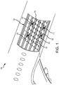
FIG. 1 , anaircraft 100 is illustrated having acargo compartment 102. Acargo door 106 provides access tocargo compartment 102 fromoutside aircraft 100. To facilitate movement of a ULD withincargo compartment 102, as the ULD is loaded, stowed, and unloaded.Cargo compartment 102 may include a number of raisedroller elements 104. Raisedroller elements 104, in various embodiments, may be part ofelongated roller trays 108 that extend longitudinally along a length ofcargo compartment 102. The ULDs sit atop raisedroller elements 104, which facilitate rolling movement of the ULDs withincargo compartment 102. In various embodiments,cargo compartment 102 may be equipped with one or more power drive units (PDUs) 110.PDUs 110 may comprise a tire that can be selectively raised, and selectively energized to propel a ULD acrosscargo compartment 102 in a desired direction. As disclosed herein, the tire may include a number of discrete traction elements. The discrete traction elements are coupled to a hub of the tire independently from one another. The traction elements may thus be removed and/or replaced individually. In accordance with various embodiments, the traction elements may be removed from the tire, without having to remove the tire from the PDU. - Referring now to
FIG. 2A , aPDU 110 is illustrated, in accordance with various embodiments. In various embodiments,PDU 110 includes a mountingring 122, which supports a rotatable frame orpivot plate 124.Pivot plate 124 may incorporate aremovable cover 126, which includes anopening 128 that permits atire 130 to extend upwardly to a raised active position (e.g.,tire 130 extends from a retracted position within a deck of an aircraft cargo compartment toward the ceiling of the aircraft, such that at least a portion oftire 130 protrudes through the deck of the aircraft cargo compartment.Tire 130 may rotate about an axis of rotation A-A'. As used herein, "axial" and refers to a direction parallel to axis A-A'. As used herein, "radial" refers to a direction orthogonal to axis of rotation A-A'. As used herein, "circumferential" and refers to a direction about axis of rotation A-A'. In various embodiments, one ormore skid plates 140 may be located at opposing axial ends oftire 130. Agear housing 146 may be locatedadjacent skid plate 140.Gear housing 146 is located around (i.e., houses) agear 148, with momentary reference toFIG. 2C . As described in further detail below,gear 148 may be configured to transfer rotational motion, or torque, to tire 130. - Referring now to
FIG. 2B ,PDU 110 also includes adrive motor 132 and alift actuator 134.Drive motor 132 is configured to drive rotation oftire 130 in either direction (e.g., forward or reverse) andlift actuator 134 raises and lowerstire 130 with respect to theremovable cover 126. In various embodiments, anelectrical conduit 152 may be electrically coupled to drivemotor 132.Electrical conduit 152 may carry various power inputs from a power supply and control module that are configured topower drive motor 132 andlift actuator 134.Drive motor 132 may be operationally coupled to one ormore gear trains 154. - With combined reference to
FIG. 2B and2C , in various embodiments,gear trains 154 may be located betweendrive motor 132 andgear 148. Gear trains 154 include one or more gears rotationally coupled to drivemotor 132 andgear 148. Gear trains 154 are configured to transfer rotational motion fromdrive motor 132 togear 148. - Referring now to
FIG. 2C , in various embodiments,gear 148 may be rotationally coupled to anaxle 160.Axle 160 is rotationally coupled to ahub 180 oftire 130, and configured to transfer torque tohub 180.Gear 148 may transfer torque to, and drive a rotation of,axle 160, which in turn drives a rotation oftire 130. In various embodiments,axle 160 may comprise two discrete portions (e.g.,first portion 160a andsecond portion 160b). Firstdiscrete portion 160a may be attached to seconddiscrete portion 160b by afastener 162. First and seconddiscrete portions tire 130 to be removed fromPDU 110, without having to removePDU 110 fromcargo compartment 102 ofFIG. 1 . - Referring now to
FIGs. 3A and 3B ,tire 130 is illustrated in accordance with various embodiments.Tire 130 includeshub 180 and a plurality oftraction elements 182 coupled tohub 180.Traction elements 182 are discrete from one another, such that asingle traction element 182 can be removed fromhub 180, without removing any of theother traction elements 182. In various embodiments, circumferentiallyadjacent traction elements 182 may axially overlap. For example,first traction element 182a axially overlaps (i.e., is axially adjacent to) circumferentially adjacentsecond traction element 182b, andsecond traction element 182b axially overlaps circumferentially adjacentthird traction element 182c. In various embodiments,traction elements 182 are axially overlapped such that at least twotraction elements 182 oftire 130 will contact a ULD or other load being translated bytire 130. For example, in various embodiments,first traction element 182a extends circumferentially to, at least, wherethird traction element 182c beings to axially overlapsecond traction element 182b. - In various embodiments, each
traction element 182 extends from a firstaxial end 192 oftire 130 to a secondaxial end 194 oftire 130. Secondaxial end 194 is axially opposite firstaxial end 192. Eachtraction element 182 comprises a first axially extendedge 196a and a secondaxially extending edge 196b. Second axially extendingedge 196b is generally circumferentially opposite first axially extendingedge 196a. First and second axially extendingedges axial end 192 oftire 130 to secondaxial end 194. The first axially extendingedge 196a of eachtraction element 182 is circumferentially adjacent to the secondaxially extending edge 196b of theadjacent traction element 182. Eachtraction element 182 further comprises a firstcircumferentially extending edge 198a and a secondcircumferentially extending edge 198b. Second circumferentially extendingedge 198b is axially opposite first circumferentially extendingedge 198a. First and second circumferentially extendingedges edge 196a to second axially extendingedge 196b. In various embodiments, first axially extendingedge 196a may be oriented at an acute angle theta (θ) with respect to first circumferentially extendingedge 198a, and at an obtuse angle beta (β) with respect to second circumferentially extendingedge 198b. Second axially extendingedge 196b may be oriented an acute angle theta (θ) with respect to second circumferentially extendingedge 198b, and an obtuse angle beta (β) with respect to first circumferentially extendingedge 198a. First and second axially extendingedges - With reference to
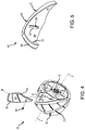
FIG. 4 and FIG. 5 , eachtraction element 182 oftire 130 includes abacking plate 184 and anelastomeric material 186 bonded tobacking plate 184. Backingplate 184 may comprise a rigid material. In various embodiments, backingplate 184 may be made from a metal or metal alloy, such as, for example, aluminum, titanium stainless steel, etc. Backingplate 184 may also be made from polyvinyl chloride, ceramic, wood, or any other suitably rigid structure. - In various embodiments, backing
plate 184 may define anaperture 200.Aperture 200 is configured to receive aprotrusion 202 extending from a radiallyoutward surface 216 ofhub 180. Locatingprotrusion 202 withinaperture 200 may facilitate transmission of torque fromhub 180 totraction element 182. While eachtraction element 182 is illustrated as including oneaperture 200 having a generally rectangular shape, it is further contemplated and understood that eachbacking plate 184 may define any number ofapertures 200, having any desired geometry with each aperture configured to receive a protrusion of a corresponding geometry extending from radially outward surface 216 ofhub 180. In various embodiments, backplate 184 may include a protrusion and radiallyoutward surface 216 ofhub 180 may define an aperture configured to receive the protrusion. - Each
traction element 182 may be coupled tohub 180 via one ormore fasteners 204.Fasteners 204 may comprise a screw, rivet, clip, nut and bolt, or other suitable securement device.Hub 180 may includeorifices 206 configured to receivefasteners 204.Fasteners 204 may be located throughapertures 190 defined bytraction elements 182. - In various embodiments,
elastomeric material 186 may define one or more slots, or grooves, 210.Grooves 210 are configured to extend partially throughelastomeric material 186 in the radial direction, such that at least a portion ofelastomeric material 186 remains between a radially inward surface ofgroove 210 andbacking plate 184. -
Elastomeric material 186 may be configured to have a desired spring constant.Elastomeric material 186 may comprise nitrile rubber, carboxylated nitrile rubber, hydrogenated nitrile butadiene rubber, polyether polyurethane, or other elastomeric material. In various embodiments, a hardness ofelastomeric material 186 may be greater proximate first and second circumferentially extendingedges area 195 between first and second circumferentially extendingedges elastomeric material 186 at first and second axial ends 192, 194 oftire 130 may better protecttire 130 from being damaged by loads moving axially acrosstire 130. In various embodiments, the material properties (e.g., hardness, elasticity, etc.) ofelastomeric material 186 may vary between circumferentiallyadjacent traction elements 182. For example, with momentary reference toFIG. 3A ,elastomeric material 186a offirst traction element 182a may be different fromelastomeric material 186b ofsecond traction element 182b. - Returning to
FIG. 2C ,traction elements 182 oftire 130 can be replaced without having to removehub 180 fromPDU 110. This reduces time and effort associated with removing theentire tire 130 as well as the cost of replacinghub 180 and each time a traction portion oftire 130 needs replacing. - Though
tire 130 has been disclosed herein as being compatible with use on aircraft systems, such as PDUs, other uses are contemplated, such as for providing motive force in factories, package delivery centers, luggage transportation, tractors, automobiles, and/or other systems and articles where it may be desirable to replace tire tractions elements without removing the entire tire. - In various embodiments, and with reference to
FIG. 6 , a PDU 220, similar toPDU 110 inFIGs. 2A and 2B , is illustrated, in accordance with various embodiments. PDU 220 includes a mountingring 222, apivot plate 224, aremovable cover 226, atire 230, andskid plates 240 located at opposing axial ends oftire 230.Tire 230 is similar totire 130 inFIG. 3A , and includes a plurality ofdiscrete traction elements 282.Traction elements 282 each include abacking plate 284 and anelastomeric material 286 bonded to thebacking plate 284.Traction elements 282 are configured to axially overlap (e.g.,first traction element 282a is axially adjacentsecond traction element 282b). - PDU 220 may also include a drive motor and lift actuator, similar to
PDU 110. The drive motor may be operationally coupled to one ormore gear trains 254. Gear trains 254 may be located between the drive motor and agear 248 housed within agear housing 246. Gear trains 254 are configured to transfer rotational motion from the drive motor to gear 248.Gear 248 may be rotationally coupled to anaxle 260.Axle 260 is rotationally coupled to ahub 280 oftire 230.Gear 248 may transfer torque to, and drive a rotation of,axle 260, which in turn drives a rotation oftire 230.Axle 260 may comprise of a single, unibody structure, extending between axial ends oftire 230, astraction elements 282 oftire 230 can be replaced without having to removehub 280 from PDU 220. - Referring to
FIG. 7 , atire 330 having discrete traction elements 382 is illustrated, in accordance with various embodiments. In various embodiments,tire 330 may be designed to include a mixed configuration of tread patterns, durometers, studs, etc. For example, the elastomeric material 386 of traction elements 382 may be customized to build up a unique configuration of hardness and elasticity acrosstire 330. In various embodiments,tire 330 may include a set offirst traction elements 382a designed for increased traction, or "grip,", betweentire 330 and a pallet or other load being translated bytire 330 and a set ofsecond traction elements 382b designed for increased life (i.e., decreased wear). - In various embodiments,
elastomeric material 386a offirst traction elements 382a may be more elastic and/or more easily compressed as compared toelastomeric material 386b ofsecond traction elements 382b. The increased elasticity may generate increased friction betweenfirst traction elements 382a a load being moved bytire 330, while the increased hardness may increase the wear life ofsecond traction elements 382b. - In various embodiments, a tread pattern of
first traction elements 382a may from a tread pattern ofsecond traction elements 382b. For example,elastomeric material 386a may definegrooves 390a andelastomeric material 386b may definegrooves 390b. The geometry, depth, and/or number ofgrooves 390a infirst traction elements 382a may differ from the may geometry, depth, and/or number ofgrooves 390b insecond traction elements 382b. For example,grooves 390a may be oriented in as an "X," whilegrooves 390b may be single linear strips. The geometry, depth, and/or number ofgrooves 390a may increase the friction betweenfirst traction elements 382a and a load being moved bytire 330, while the geometry, depth, and/or number ofgrooves 390a may increase the wear life ofsecond traction elements 382b. - In various embodiments, a radial thickness of
elastomeric material 386a may be different from a radial thickness ofelastomeric material 386b. In various, a geometry offirst traction elements 382a may differ from a geometry ofsecond traction elements 382b. For example, a shape of thebacking plates 384a offirst traction elements 382a may be different from the shape of thebacking plates 384b ofsecond traction elements 382b. Whiletire 330 is illustrated as includes two sets of discrete traction elements, it is further contemplate and understood thattire 330 may include any number and combination of unique traction elements. - Traction elements 382 are coupled to a
hub 380 oftire 330. As discussed in further detail below, a diameter D1 ofhub 380 at radiallyinward surface 381 may be greater than a diameter D2 oftire 130, with momentary reference toFIG. 4 , to accommodate components (e.g., gears) of PDU. - In various embodiments, and with reference to
FIG. 8 , aPDU 320 includingtire 330 is illustrated, in accordance with various embodiments.PDU 320 may be similar toPDU 110 inFIGs. 2A and 2B .PDU 320 includes a mountingring 322, apivot plate 324, aremovable cover 326, atire 330, andskid plates 340 located at opposing axial ends oftire 330. - PDU 220 may also include a drive motor and a lift actuator, similar to
PDU 110. The drive motor may be operationally coupled to one ormore gear trains 354. Gear trains 354 may be located between the drive motor and agear 348 housed within agear housing 346. Gear trains 354 are configured to transfer rotational motion from the drive motor to gear 348.Gear 348 may be rotationally coupled tohub 380 viagear trains inward surface 381 ofhub 380 may engage (i.e. mesh with) a gear ofgear train 350.Gear 348 may transfer torque to, and drive a rotation of,gear train 352, which drives a rotation ofgear train 350, which drives a rotation oftire 230. Portions ofgear trains volume 383 defined by radiallyinward surface 381 ofhub 380, as traction elements 382 can be replaced without removinghub 380 fromPDU 320. Locating components ofPDU 320 withinvolume 383 may allow a size ofPDU 320 to be decreased. - Benefits, other advantages, and solutions to problems have been described herein with regard to specific embodiments. Furthermore, the connecting lines shown in the various figures contained herein are intended to represent exemplary functional relationships and/or physical couplings between the various elements. It should be noted that many alternative or additional functional relationships or physical connections may be present in a practical system. However, the benefits, advantages, solutions to problems, and any elements that may cause any benefit, advantage, or solution to occur or become more pronounced are not to be construed as critical, required, or essential features or elements of the inventions. The scope of the inventions is accordingly to be limited by nothing other than the appended claims, in which reference to an element in the singular is not intended to mean "one and only one" unless explicitly so stated, but rather "one or more." Moreover, where a phrase similar to "at least one of A, B, or C" is used in the claims, it is intended that the phrase be interpreted to mean that A alone may be present in an embodiment, B alone may be present in an embodiment, C alone may be present in an embodiment, or that any combination of the elements A, B and C may be present in a single embodiment; for example, A and B, A and C, B and C, or A and B and C.
- Systems, methods and apparatus are provided herein. In the detailed description herein, references to "various embodiments", "one embodiment", "an embodiment", "an example embodiment", etc., indicate that the embodiment described may include a particular feature, structure, or characteristic, but every embodiment may not necessarily include the particular feature, structure, or characteristic. Moreover, such phrases are not necessarily referring to the same embodiment. Further, when a particular feature, structure, or characteristic is described in connection with an embodiment, it is submitted that it is within the knowledge of one skilled in the art to affect such feature, structure, or characteristic in connection with other embodiments whether or not explicitly described. After reading the description, it will be apparent to one skilled in the relevant art(s) how to implement the disclosure in alternative embodiments.
- Furthermore, no element, component, or method step in the present disclosure is intended to be dedicated to the public regardless of whether the element, component, or method step is explicitly recited in the claims. No claim element is intended to invoke 35 U.S.C. 112(f) unless the element is expressly recited using the phrase "means for." As used herein, the terms "comprises", "comprising", or any other variation thereof, are intended to cover a non-exclusive inclusion, such that a process, method, article, or apparatus that comprises a list of elements does not include only those elements but may include other elements not expressly listed or inherent to such process, method, article, or apparatus.
Claims (15)
- A tire, comprising:
a hub;a first traction element coupled to the hub; anda second traction element coupled to the hub, wherein the second traction element is discrete from the first traction element. - The tire of claim 1, wherein the first traction element comprises a first backing plate and a first elastomeric material bonded to the first backing plate, and wherein the second traction element comprises a second backing plate and a second elastomeric material bonded to the second backing plate.
- The tire of claim 2, wherein the first backing plate defines an aperture configured to receive a protrusion extending from the hub.
- The tire of claim 2 or 3, wherein a first groove pattern defined by the first elastomeric material is different from a second groove pattern define by the second elastomeric material.
- The tire of any of claims 2 to 4, wherein the first elastomeric material is different from the second elastomeric material.
- The tire of any of the preceding claims, wherein the first traction element axially overlaps the second traction element.
- The tire of any of the preceding claims, wherein an axially extending edge of the first traction element is oriented at at least one of an acute angle or an obtuse angle with respect to a circumferentially extending edge of the first traction element.
- The tire of any of the preceding claims, further comprising:a first fastener coupling the first traction element to the hub; anda second fastener coupling the second traction element to the hub.
- A power drive unit, comprising:a tire according to any of the preceding claims; anda drive motor configured to drive a rotation of the tire.
- The power drive unit of claim 9, further comprising a gear located within a volume defined by a radially inward surface of the hub.
- The power drive unit of claim 9 or 10, further comprising an axle rotationally coupled to the hub, wherein the axle comprises a single unibody piece extending between opposing axial ends of the tire.
- A tire for a power drive unit, comprising:a first traction element comprising a first backing plate and a first elastomeric material bonded to the first backing plate; anda second traction element adjacent to the first traction element and comprising a second backing plate and a second elastomeric material bonded to the second backing plate.
- The tire of claim 12, wherein the first traction element axially overlaps the second traction element.
- The tire of claim 12 or 13, further comprising a hub, wherein the first traction element and the second traction element are coupled to the hub.
- The tire of claim 14, wherein the first backing plate defines a first aperture configured to receive a first protrusion extending from the hub, and wherein the second backing plate defines a second aperture configured to receive a second protrusion extending from the hub.
Applications Claiming Priority (1)
| Application Number | Priority Date | Filing Date | Title |
|---|---|---|---|
| US16/135,798 US11331949B2 (en) | 2018-09-19 | 2018-09-19 | Tire having replaceable discrete traction elements |
Publications (2)
| Publication Number | Publication Date |
|---|---|
| EP3626614A1 true EP3626614A1 (en) | 2020-03-25 |
| EP3626614B1 EP3626614B1 (en) | 2023-06-07 |
Family
ID=67997369
Family Applications (1)
| Application Number | Title | Priority Date | Filing Date |
|---|---|---|---|
| EP19197811.3A Active EP3626614B1 (en) | 2018-09-19 | 2019-09-17 | Tire having replaceable discrete traction elements |
Country Status (2)
| Country | Link |
|---|---|
| US (1) | US11331949B2 (en) |
| EP (1) | EP3626614B1 (en) |
Families Citing this family (3)
| Publication number | Priority date | Publication date | Assignee | Title |
|---|---|---|---|---|
| US12522022B2 (en) | 2021-11-17 | 2026-01-13 | Goodrich Corporation | Composite PDU tire in an aircraft cargo handling system |
| US20230249493A1 (en) * | 2022-02-04 | 2023-08-10 | Goodrich Corporation | Modular pdu wheel assembly |
| USD1078594S1 (en) | 2024-07-30 | 2025-06-10 | Ironwood Designs, Llc | Wheel segment of a segmented wheel |
Citations (3)
| Publication number | Priority date | Publication date | Assignee | Title |
|---|---|---|---|---|
| FR363386A (en) * | 1906-02-17 | 1906-07-30 | William Baker Hartridge | Improvements to wheels and elastic tires for road vehicles |
| US7717252B2 (en) * | 2007-11-14 | 2010-05-18 | Goodrich Corporation | Cargo power drive unit with uniform bi-directional drive traction |
| EP2918496A2 (en) * | 2014-03-10 | 2015-09-16 | Goodrich Corporation | Compliant tire |
Family Cites Families (13)
| Publication number | Priority date | Publication date | Assignee | Title |
|---|---|---|---|---|
| US2886091A (en) | 1957-10-04 | 1959-05-12 | William R Hines | Wheel traction device |
| US4086947A (en) | 1976-01-05 | 1978-05-02 | The Goodyear Tire & Rubber Company | Traction shoe seal |
| US4589542A (en) * | 1983-12-19 | 1986-05-20 | The Boeing Company | Cargo drive unit |
| DE4224818C2 (en) * | 1992-07-27 | 1995-06-08 | Telair Int Cargo Sys Gmbh | Roller drive unit |
| CA2204053A1 (en) | 1997-04-30 | 1998-10-30 | Louis Beauchemin | Removable tire traction device |
| WO2007107812A1 (en) | 2006-03-20 | 2007-09-27 | Cumberlege, John, Pear | Conveyor belt roller or pulley with renewable contact surface |
| IL222208A (en) | 2012-09-27 | 2017-02-28 | Israel Aerospace Ind Ltd | Cargo handling system, method and apparatus |
| KR101908254B1 (en) * | 2015-03-31 | 2018-10-15 | 혼다 기켄 고교 가부시키가이샤 | Separator for fuel cells and method for producing same |
| JP6443508B1 (en) | 2017-07-25 | 2018-12-26 | 横浜ゴム株式会社 | Pneumatic tire |
| WO2019023514A1 (en) * | 2017-07-26 | 2019-01-31 | gowheels, Inc. | Cart wheel assembly with replaceable tire |
| US11279170B2 (en) * | 2018-07-19 | 2022-03-22 | Gacw Incorporated | Wheel assembly including flexible inboard seal and related methods |
| US10800527B2 (en) * | 2018-08-17 | 2020-10-13 | Goodrich Corporation | Omni directional turntable assembly |
| US11148468B1 (en) * | 2021-05-03 | 2021-10-19 | Abraham Ballena | Non-pneumatic tire with individual tire modules |
-
2018
- 2018-09-19 US US16/135,798 patent/US11331949B2/en active Active
-
2019
- 2019-09-17 EP EP19197811.3A patent/EP3626614B1/en active Active
Patent Citations (3)
| Publication number | Priority date | Publication date | Assignee | Title |
|---|---|---|---|---|
| FR363386A (en) * | 1906-02-17 | 1906-07-30 | William Baker Hartridge | Improvements to wheels and elastic tires for road vehicles |
| US7717252B2 (en) * | 2007-11-14 | 2010-05-18 | Goodrich Corporation | Cargo power drive unit with uniform bi-directional drive traction |
| EP2918496A2 (en) * | 2014-03-10 | 2015-09-16 | Goodrich Corporation | Compliant tire |
Also Published As
| Publication number | Publication date |
|---|---|
| US20200086689A1 (en) | 2020-03-19 |
| EP3626614B1 (en) | 2023-06-07 |
| US11331949B2 (en) | 2022-05-17 |
Similar Documents
| Publication | Publication Date | Title |
|---|---|---|
| EP3626614B1 (en) | Tire having replaceable discrete traction elements | |
| US12078236B2 (en) | Electric drive unit with gear shaft, rotor shaft and three bearings | |
| US7950428B2 (en) | Non-pneumatic tire | |
| US11479107B2 (en) | Selectively attachable and detachable axial hub motor | |
| US6315109B1 (en) | Split roller wheel and method of assembly | |
| US10220940B2 (en) | Aircraft steering system | |
| KR20220147671A (en) | wheel | |
| CN111846196B (en) | Removable battery compression device | |
| EP3616940B1 (en) | Omnidirectional wheel | |
| US11535359B2 (en) | Flexible and simple turnaround cargo handling assemblies | |
| JP6608385B2 (en) | Roller gear for drive system | |
| US20160101846A1 (en) | Powered aircraft wheel design | |
| EP2918496B1 (en) | Compliant tire | |
| US10259312B2 (en) | Space-maximizing clutch arrangement for vehicle drive wheel | |
| US9688096B2 (en) | Disk wheel | |
| US9493033B2 (en) | Aircraft wheel bearing arrangement | |
| WO1996017771A1 (en) | Landing gear axle steering without walking beam | |
| US3154126A (en) | Wide base wheel tire assembly | |
| US20230116108A1 (en) | De-lamination resistant and integrated visual wear indicator tire hub | |
| US20230249493A1 (en) | Modular pdu wheel assembly | |
| EP3415429A1 (en) | Lift roller for power drive unit | |
| US12522022B2 (en) | Composite PDU tire in an aircraft cargo handling system |
Legal Events
| Date | Code | Title | Description |
|---|---|---|---|
| PUAI | Public reference made under article 153(3) epc to a published international application that has entered the european phase |
Free format text: ORIGINAL CODE: 0009012 |
|
| STAA | Information on the status of an ep patent application or granted ep patent |
Free format text: STATUS: THE APPLICATION HAS BEEN PUBLISHED |
|
| AK | Designated contracting states |
Kind code of ref document: A1 Designated state(s): AL AT BE BG CH CY CZ DE DK EE ES FI FR GB GR HR HU IE IS IT LI LT LU LV MC MK MT NL NO PL PT RO RS SE SI SK SM TR |
|
| AX | Request for extension of the european patent |
Extension state: BA ME |
|
| STAA | Information on the status of an ep patent application or granted ep patent |
Free format text: STATUS: REQUEST FOR EXAMINATION WAS MADE |
|
| 17P | Request for examination filed |
Effective date: 20200924 |
|
| RBV | Designated contracting states (corrected) |
Designated state(s): AL AT BE BG CH CY CZ DE DK EE ES FI FR GB GR HR HU IE IS IT LI LT LU LV MC MK MT NL NO PL PT RO RS SE SI SK SM TR |
|
| STAA | Information on the status of an ep patent application or granted ep patent |
Free format text: STATUS: EXAMINATION IS IN PROGRESS |
|
| 17Q | First examination report despatched |
Effective date: 20210701 |
|
| GRAP | Despatch of communication of intention to grant a patent |
Free format text: ORIGINAL CODE: EPIDOSNIGR1 |
|
| STAA | Information on the status of an ep patent application or granted ep patent |
Free format text: STATUS: GRANT OF PATENT IS INTENDED |
|
| INTG | Intention to grant announced |
Effective date: 20221209 |
|
| GRAS | Grant fee paid |
Free format text: ORIGINAL CODE: EPIDOSNIGR3 |
|
| GRAA | (expected) grant |
Free format text: ORIGINAL CODE: 0009210 |
|
| STAA | Information on the status of an ep patent application or granted ep patent |
Free format text: STATUS: THE PATENT HAS BEEN GRANTED |
|
| AK | Designated contracting states |
Kind code of ref document: B1 Designated state(s): AL AT BE BG CH CY CZ DE DK EE ES FI FR GB GR HR HU IE IS IT LI LT LU LV MC MK MT NL NO PL PT RO RS SE SI SK SM TR |
|
| REG | Reference to a national code |
Ref country code: GB Ref legal event code: FG4D |
|
| REG | Reference to a national code |
Ref country code: CH Ref legal event code: EP Ref country code: AT Ref legal event code: REF Ref document number: 1574284 Country of ref document: AT Kind code of ref document: T Effective date: 20230615 |
|
| REG | Reference to a national code |
Ref country code: DE Ref legal event code: R096 Ref document number: 602019029867 Country of ref document: DE |
|
| P01 | Opt-out of the competence of the unified patent court (upc) registered |
Effective date: 20230606 |
|
| REG | Reference to a national code |
Ref country code: LT Ref legal event code: MG9D |
|
| REG | Reference to a national code |
Ref country code: NL Ref legal event code: MP Effective date: 20230607 |
|
| PG25 | Lapsed in a contracting state [announced via postgrant information from national office to epo] |
Ref country code: SE Free format text: LAPSE BECAUSE OF FAILURE TO SUBMIT A TRANSLATION OF THE DESCRIPTION OR TO PAY THE FEE WITHIN THE PRESCRIBED TIME-LIMIT Effective date: 20230607 Ref country code: NO Free format text: LAPSE BECAUSE OF FAILURE TO SUBMIT A TRANSLATION OF THE DESCRIPTION OR TO PAY THE FEE WITHIN THE PRESCRIBED TIME-LIMIT Effective date: 20230907 Ref country code: ES Free format text: LAPSE BECAUSE OF FAILURE TO SUBMIT A TRANSLATION OF THE DESCRIPTION OR TO PAY THE FEE WITHIN THE PRESCRIBED TIME-LIMIT Effective date: 20230607 |
|
| REG | Reference to a national code |
Ref country code: AT Ref legal event code: MK05 Ref document number: 1574284 Country of ref document: AT Kind code of ref document: T Effective date: 20230607 |
|
| PG25 | Lapsed in a contracting state [announced via postgrant information from national office to epo] |
Ref country code: RS Free format text: LAPSE BECAUSE OF FAILURE TO SUBMIT A TRANSLATION OF THE DESCRIPTION OR TO PAY THE FEE WITHIN THE PRESCRIBED TIME-LIMIT Effective date: 20230607 Ref country code: NL Free format text: LAPSE BECAUSE OF FAILURE TO SUBMIT A TRANSLATION OF THE DESCRIPTION OR TO PAY THE FEE WITHIN THE PRESCRIBED TIME-LIMIT Effective date: 20230607 Ref country code: LV Free format text: LAPSE BECAUSE OF FAILURE TO SUBMIT A TRANSLATION OF THE DESCRIPTION OR TO PAY THE FEE WITHIN THE PRESCRIBED TIME-LIMIT Effective date: 20230607 Ref country code: LT Free format text: LAPSE BECAUSE OF FAILURE TO SUBMIT A TRANSLATION OF THE DESCRIPTION OR TO PAY THE FEE WITHIN THE PRESCRIBED TIME-LIMIT Effective date: 20230607 Ref country code: HR Free format text: LAPSE BECAUSE OF FAILURE TO SUBMIT A TRANSLATION OF THE DESCRIPTION OR TO PAY THE FEE WITHIN THE PRESCRIBED TIME-LIMIT Effective date: 20230607 Ref country code: GR Free format text: LAPSE BECAUSE OF FAILURE TO SUBMIT A TRANSLATION OF THE DESCRIPTION OR TO PAY THE FEE WITHIN THE PRESCRIBED TIME-LIMIT Effective date: 20230908 |
|
| PG25 | Lapsed in a contracting state [announced via postgrant information from national office to epo] |
Ref country code: FI Free format text: LAPSE BECAUSE OF FAILURE TO SUBMIT A TRANSLATION OF THE DESCRIPTION OR TO PAY THE FEE WITHIN THE PRESCRIBED TIME-LIMIT Effective date: 20230607 |
|
| PG25 | Lapsed in a contracting state [announced via postgrant information from national office to epo] |
Ref country code: SK Free format text: LAPSE BECAUSE OF FAILURE TO SUBMIT A TRANSLATION OF THE DESCRIPTION OR TO PAY THE FEE WITHIN THE PRESCRIBED TIME-LIMIT Effective date: 20230607 |
|
| PG25 | Lapsed in a contracting state [announced via postgrant information from national office to epo] |
Ref country code: IS Free format text: LAPSE BECAUSE OF FAILURE TO SUBMIT A TRANSLATION OF THE DESCRIPTION OR TO PAY THE FEE WITHIN THE PRESCRIBED TIME-LIMIT Effective date: 20231007 |
|
| PG25 | Lapsed in a contracting state [announced via postgrant information from national office to epo] |
Ref country code: SM Free format text: LAPSE BECAUSE OF FAILURE TO SUBMIT A TRANSLATION OF THE DESCRIPTION OR TO PAY THE FEE WITHIN THE PRESCRIBED TIME-LIMIT Effective date: 20230607 Ref country code: SK Free format text: LAPSE BECAUSE OF FAILURE TO SUBMIT A TRANSLATION OF THE DESCRIPTION OR TO PAY THE FEE WITHIN THE PRESCRIBED TIME-LIMIT Effective date: 20230607 Ref country code: RO Free format text: LAPSE BECAUSE OF FAILURE TO SUBMIT A TRANSLATION OF THE DESCRIPTION OR TO PAY THE FEE WITHIN THE PRESCRIBED TIME-LIMIT Effective date: 20230607 Ref country code: PT Free format text: LAPSE BECAUSE OF FAILURE TO SUBMIT A TRANSLATION OF THE DESCRIPTION OR TO PAY THE FEE WITHIN THE PRESCRIBED TIME-LIMIT Effective date: 20231009 Ref country code: IS Free format text: LAPSE BECAUSE OF FAILURE TO SUBMIT A TRANSLATION OF THE DESCRIPTION OR TO PAY THE FEE WITHIN THE PRESCRIBED TIME-LIMIT Effective date: 20231007 Ref country code: EE Free format text: LAPSE BECAUSE OF FAILURE TO SUBMIT A TRANSLATION OF THE DESCRIPTION OR TO PAY THE FEE WITHIN THE PRESCRIBED TIME-LIMIT Effective date: 20230607 Ref country code: CZ Free format text: LAPSE BECAUSE OF FAILURE TO SUBMIT A TRANSLATION OF THE DESCRIPTION OR TO PAY THE FEE WITHIN THE PRESCRIBED TIME-LIMIT Effective date: 20230607 Ref country code: AT Free format text: LAPSE BECAUSE OF FAILURE TO SUBMIT A TRANSLATION OF THE DESCRIPTION OR TO PAY THE FEE WITHIN THE PRESCRIBED TIME-LIMIT Effective date: 20230607 |
|
| PG25 | Lapsed in a contracting state [announced via postgrant information from national office to epo] |
Ref country code: PL Free format text: LAPSE BECAUSE OF FAILURE TO SUBMIT A TRANSLATION OF THE DESCRIPTION OR TO PAY THE FEE WITHIN THE PRESCRIBED TIME-LIMIT Effective date: 20230607 |
|
| REG | Reference to a national code |
Ref country code: DE Ref legal event code: R097 Ref document number: 602019029867 Country of ref document: DE |
|
| PLBE | No opposition filed within time limit |
Free format text: ORIGINAL CODE: 0009261 |
|
| STAA | Information on the status of an ep patent application or granted ep patent |
Free format text: STATUS: NO OPPOSITION FILED WITHIN TIME LIMIT |
|
| PG25 | Lapsed in a contracting state [announced via postgrant information from national office to epo] |
Ref country code: DK Free format text: LAPSE BECAUSE OF FAILURE TO SUBMIT A TRANSLATION OF THE DESCRIPTION OR TO PAY THE FEE WITHIN THE PRESCRIBED TIME-LIMIT Effective date: 20230607 |
|
| REG | Reference to a national code |
Ref country code: CH Ref legal event code: PL |
|
| PG25 | Lapsed in a contracting state [announced via postgrant information from national office to epo] |
Ref country code: SI Free format text: LAPSE BECAUSE OF FAILURE TO SUBMIT A TRANSLATION OF THE DESCRIPTION OR TO PAY THE FEE WITHIN THE PRESCRIBED TIME-LIMIT Effective date: 20230607 |
|
| 26N | No opposition filed |
Effective date: 20240308 |
|
| PG25 | Lapsed in a contracting state [announced via postgrant information from national office to epo] |
Ref country code: LU Free format text: LAPSE BECAUSE OF NON-PAYMENT OF DUE FEES Effective date: 20230917 |
|
| REG | Reference to a national code |
Ref country code: BE Ref legal event code: MM Effective date: 20230930 |
|
| PG25 | Lapsed in a contracting state [announced via postgrant information from national office to epo] |
Ref country code: SI Free format text: LAPSE BECAUSE OF FAILURE TO SUBMIT A TRANSLATION OF THE DESCRIPTION OR TO PAY THE FEE WITHIN THE PRESCRIBED TIME-LIMIT Effective date: 20230607 Ref country code: LU Free format text: LAPSE BECAUSE OF NON-PAYMENT OF DUE FEES Effective date: 20230917 Ref country code: IT Free format text: LAPSE BECAUSE OF FAILURE TO SUBMIT A TRANSLATION OF THE DESCRIPTION OR TO PAY THE FEE WITHIN THE PRESCRIBED TIME-LIMIT Effective date: 20230607 Ref country code: MC Free format text: LAPSE BECAUSE OF FAILURE TO SUBMIT A TRANSLATION OF THE DESCRIPTION OR TO PAY THE FEE WITHIN THE PRESCRIBED TIME-LIMIT Effective date: 20230607 |
|
| REG | Reference to a national code |
Ref country code: IE Ref legal event code: MM4A |
|
| PG25 | Lapsed in a contracting state [announced via postgrant information from national office to epo] |
Ref country code: IE Free format text: LAPSE BECAUSE OF NON-PAYMENT OF DUE FEES Effective date: 20230917 |
|
| PG25 | Lapsed in a contracting state [announced via postgrant information from national office to epo] |
Ref country code: CH Free format text: LAPSE BECAUSE OF NON-PAYMENT OF DUE FEES Effective date: 20230930 |
|
| PG25 | Lapsed in a contracting state [announced via postgrant information from national office to epo] |
Ref country code: IE Free format text: LAPSE BECAUSE OF NON-PAYMENT OF DUE FEES Effective date: 20230917 Ref country code: CH Free format text: LAPSE BECAUSE OF NON-PAYMENT OF DUE FEES Effective date: 20230930 |
|
| PG25 | Lapsed in a contracting state [announced via postgrant information from national office to epo] |
Ref country code: BE Free format text: LAPSE BECAUSE OF NON-PAYMENT OF DUE FEES Effective date: 20230930 |
|
| PG25 | Lapsed in a contracting state [announced via postgrant information from national office to epo] |
Ref country code: BG Free format text: LAPSE BECAUSE OF FAILURE TO SUBMIT A TRANSLATION OF THE DESCRIPTION OR TO PAY THE FEE WITHIN THE PRESCRIBED TIME-LIMIT Effective date: 20230607 |
|
| PG25 | Lapsed in a contracting state [announced via postgrant information from national office to epo] |
Ref country code: BG Free format text: LAPSE BECAUSE OF FAILURE TO SUBMIT A TRANSLATION OF THE DESCRIPTION OR TO PAY THE FEE WITHIN THE PRESCRIBED TIME-LIMIT Effective date: 20230607 |
|
| PG25 | Lapsed in a contracting state [announced via postgrant information from national office to epo] |
Ref country code: CY Free format text: LAPSE BECAUSE OF FAILURE TO SUBMIT A TRANSLATION OF THE DESCRIPTION OR TO PAY THE FEE WITHIN THE PRESCRIBED TIME-LIMIT; INVALID AB INITIO Effective date: 20190917 |
|
| PG25 | Lapsed in a contracting state [announced via postgrant information from national office to epo] |
Ref country code: HU Free format text: LAPSE BECAUSE OF FAILURE TO SUBMIT A TRANSLATION OF THE DESCRIPTION OR TO PAY THE FEE WITHIN THE PRESCRIBED TIME-LIMIT; INVALID AB INITIO Effective date: 20190917 |
|
| PGFP | Annual fee paid to national office [announced via postgrant information from national office to epo] |
Ref country code: DE Payment date: 20250820 Year of fee payment: 7 |
|
| PGFP | Annual fee paid to national office [announced via postgrant information from national office to epo] |
Ref country code: GB Payment date: 20250820 Year of fee payment: 7 |
|
| PGFP | Annual fee paid to national office [announced via postgrant information from national office to epo] |
Ref country code: FR Payment date: 20250820 Year of fee payment: 7 |
|
| PG25 | Lapsed in a contracting state [announced via postgrant information from national office to epo] |
Ref country code: TR Free format text: LAPSE BECAUSE OF FAILURE TO SUBMIT A TRANSLATION OF THE DESCRIPTION OR TO PAY THE FEE WITHIN THE PRESCRIBED TIME-LIMIT Effective date: 20230607 |