EP3626608B1 - A wing tip device - Google Patents
A wing tip device Download PDFInfo
- Publication number
- EP3626608B1 EP3626608B1 EP19196614.2A EP19196614A EP3626608B1 EP 3626608 B1 EP3626608 B1 EP 3626608B1 EP 19196614 A EP19196614 A EP 19196614A EP 3626608 B1 EP3626608 B1 EP 3626608B1
- Authority
- EP
- European Patent Office
- Prior art keywords
- wing tip
- tip device
- wing
- device element
- outboard
- Prior art date
- Legal status (The legal status is an assumption and is not a legal conclusion. Google has not performed a legal analysis and makes no representation as to the accuracy of the status listed.)
- Active
Links
- 238000000034 method Methods 0.000 claims description 6
- 238000009420 retrofitting Methods 0.000 claims description 4
- 230000007423 decrease Effects 0.000 description 2
- 230000007704 transition Effects 0.000 description 2
- RZVHIXYEVGDQDX-UHFFFAOYSA-N 9,10-anthraquinone Chemical compound C1=CC=C2C(=O)C3=CC=CC=C3C(=O)C2=C1 RZVHIXYEVGDQDX-UHFFFAOYSA-N 0.000 description 1
- 230000009286 beneficial effect Effects 0.000 description 1
- 230000000295 complement effect Effects 0.000 description 1
- 238000010276 construction Methods 0.000 description 1
- 238000012986 modification Methods 0.000 description 1
- 230000004048 modification Effects 0.000 description 1
- 230000003019 stabilising effect Effects 0.000 description 1
Images


Classifications
-
- B—PERFORMING OPERATIONS; TRANSPORTING
- B64—AIRCRAFT; AVIATION; COSMONAUTICS
- B64C—AEROPLANES; HELICOPTERS
- B64C3/00—Wings
- B64C3/38—Adjustment of complete wings or parts thereof
-
- B—PERFORMING OPERATIONS; TRANSPORTING
- B64—AIRCRAFT; AVIATION; COSMONAUTICS
- B64C—AEROPLANES; HELICOPTERS
- B64C1/00—Fuselages; Constructional features common to fuselages, wings, stabilising surfaces or the like
- B64C1/26—Attaching the wing or tail units or stabilising surfaces
-
- B—PERFORMING OPERATIONS; TRANSPORTING
- B64—AIRCRAFT; AVIATION; COSMONAUTICS
- B64C—AEROPLANES; HELICOPTERS
- B64C23/00—Influencing air flow over aircraft surfaces, not otherwise provided for
- B64C23/06—Influencing air flow over aircraft surfaces, not otherwise provided for by generating vortices
- B64C23/065—Influencing air flow over aircraft surfaces, not otherwise provided for by generating vortices at the wing tips
- B64C23/069—Influencing air flow over aircraft surfaces, not otherwise provided for by generating vortices at the wing tips using one or more wing tip airfoil devices, e.g. winglets, splines, wing tip fences or raked wingtips
-
- B—PERFORMING OPERATIONS; TRANSPORTING
- B64—AIRCRAFT; AVIATION; COSMONAUTICS
- B64C—AEROPLANES; HELICOPTERS
- B64C3/00—Wings
- B64C3/36—Structures adapted to reduce effects of aerodynamic or other external heating
-
- B—PERFORMING OPERATIONS; TRANSPORTING
- B64—AIRCRAFT; AVIATION; COSMONAUTICS
- B64C—AEROPLANES; HELICOPTERS
- B64C3/00—Wings
- B64C3/58—Wings provided with fences or spoilers
-
- B—PERFORMING OPERATIONS; TRANSPORTING
- B64—AIRCRAFT; AVIATION; COSMONAUTICS
- B64C—AEROPLANES; HELICOPTERS
- B64C5/00—Stabilising surfaces
- B64C5/08—Stabilising surfaces mounted on, or supported by, wings
-
- Y—GENERAL TAGGING OF NEW TECHNOLOGICAL DEVELOPMENTS; GENERAL TAGGING OF CROSS-SECTIONAL TECHNOLOGIES SPANNING OVER SEVERAL SECTIONS OF THE IPC; TECHNICAL SUBJECTS COVERED BY FORMER USPC CROSS-REFERENCE ART COLLECTIONS [XRACs] AND DIGESTS
- Y02—TECHNOLOGIES OR APPLICATIONS FOR MITIGATION OR ADAPTATION AGAINST CLIMATE CHANGE
- Y02T—CLIMATE CHANGE MITIGATION TECHNOLOGIES RELATED TO TRANSPORTATION
- Y02T50/00—Aeronautics or air transport
- Y02T50/10—Drag reduction
Definitions
- the present invention relates to a wing tip device, an aircraft wing including the wing tip device and a method of fitting, or retro-fitting, a wing tip device to an aircraft wing.
- wing tip devices such as winglets, wing tip fences and raked wing tips
- increasing the effective wing span without significantly increasing the wing span can improve aerodynamic performance, for example by controlling the development of wing tip vortices and reducing induced drag (i.e. drag due to the development of lift).
- wing tip vortices Due to twist of a wing tip device, the wing tip vortices may be located inboard of the outboard-most extent of the wing tip device. This can cause an increase in induced drag. It would be beneficial to locate the wing tip vortices as far outboard as possible with due regard to the wing span and winglet size.
- WO2013/007396 A1 describes ancillary wing parts arranged on a wingtip device so as to reduce the aerodynamic drag of the overall wing tip device and reduce the loads acting on the overall wingtip device.
- DE3800110 A1 describes a method of reducing the induced drag on the wing tips of aircraft, each wing tip comprising an inboard and an outboard portion.
- US7644892 B1 describes a winglet comprising a helical portion.
- RU2264328 C1 describes a wing tip with an outboard extending portion.
- US2011/024573 A1 describes a winglet having an inboard extending portion.
- EP3296202 A1 describes a tilt-rotor aircraft having wing extensions with winglets having various protrusions.
- US6474604 B1 describes a continuous wing design.
- a wing tip device for attaching to an aircraft.
- the wing tip device comprising a first wing tip device element having a root end and a tip end, a second wing tip device element coupled to the tip end of the first wing tip device element, wherein the second wing tip device element has an inboard portion extending inboard from the tip end of the first wing tip device element and/or an outboard portion extending outboard from the tip end of the first wing tip device element, when viewed in the wing planform direction.
- the first wing tip device element includes an outboard spanwise extent, when viewed in the wing planform direction, wherein at least a trailing edge of the tip end of the first wing tip device element is inboard of the outboard spanwise extent.
- the outboard portion of the second wing tip device extends up to the outboard spanwise extent.
- the wing planform direction is the direction normal to the plane of the wing.
- the wing tip vortices can be better controlled and induced drag can be reduced.
- the outboard extending portion of the second wing tip device element can move the tip vortex outboard, thereby reducing induced drag.
- the inboard extending portion of the second wing tip device element provides a counter-rotating lifting surface, about the tip of the first wing tip device element, which can cancel out a portion of the wing loading.
- the induced drag can be reduced with little increase in tip loading and no increase in wingspan.
- an aircraft wing comprising a wing root end and a wing tip and, and a wing tip device according to the first aspect attached to the wing tip end.
- a fixed wing aircraft comprising a wing according to the second aspect.
- a method of fitting, or retro fitting, a wing tip device to an aircraft wing comprising fixing a wing tip device in accordance with the first aspect of the invention to the tip end of a wing.
- the wing tip device may have a first vertex between the first wing tip device element and the inboard portion of the second wing tip device element.
- the wing tip device may have a second vertex between the first wing tip device element and the outboard portion of the second wing tip device element.
- the second wing tip device element may be substantially planar.
- the plane of the second wing tip device element may be oriented approximately normal to a cant angle of the tip end of the first wing tip device element.
- the first wing tip device element may be twisted between the root end of the first wing tip device element and the tip end of the first wing tip device element.
- the first wing tip device element may be twisted about an axis parallel to the wing planform direction so that the first wing tip device has a toe-out angle or a toe-in angle.
- the wetted area of the second wing tip device element may be less than 40% of the wetted area of the first wingtip device element, and may be less than 20% of the wetted area of the first wing tip device element.
- the wetted area of a device portion is the area of that device portion that is exposed to the external airflow.
- the wetted area of the inboard portion may be greater than the wetted area of the outboard portion.
- the second wing tip device element may extend aft, when viewed in the wing planform direction, of the tip of the first wing tip device element.
- the trailing edge of the second wing tip device element may be positioned at the outboard spanwise extent of the wing tip device.
- the inboard portion may have an aft swept region.
- the outboard portion may have an aft swept region.
- the tip end of the first wing tip device element may have a cant angle of at least 20 degrees.
- the first wing tip device element may be a non-planar wing tip extension, a winglet, a winglet having a substantially planar portion and a non-planar wing tip extension, a blended winglet, a split winglet having an uplet and a downlet, a downlet, or a raked wing tip.
- a non-planar wing tip extension is a tip extension that extends out of the plane of the wing to which it is attached.
- a winglet is a wing-like element that extends from the wing tip.
- a winglet may extend upwardly or downwardly from the wing tip.
- a winglet may be considered to be a particular example of a non-planar wing tip extension.
- a winglet may include a substantially planar portion joined to the wing tip by a non-planar wing tip extension portion, the non-planar wing tip extension portion having an increasing curvature of local dihedral in the outboard direction.
- a blended winglet is a type of winglet that included a substantially planar portion joined to the wing tip by a curved transition portion, the transition portion having a constant radius of curvature.
- a raked wing tip device is a substantially planar wing tip extension which does not extend substantially out of the plane of the wing but has a higher sweep angle at the tip.
- a split winglet includes a wing-like lifting surface projecting upwardly (an 'uplet') from the wing, and a wing-like lifting surface projecting downwardly (a 'downlet') from the wing.
- a winglet is a wing-like lifting surface projecting upwardly (an 'uplet') or downwardly (a 'downlet') from the wing.
- the first wing tip element may include both an uplet and a downlet, e.g. a split winglet.
- the first wing tip device may include an uplet and a downlet wherein the second wingtip device element is coupled to a tip end of the uplet or downlet or a plurality of the second wing tip device elements are coupled to the uplet and downlet respectively.
- a tip of the uplet and the tip of the downlet may be located at substantially the same spanwise location, when viewed in the wing planform direction.
- the spanwise extent of the wing of the third aspect of the invention in the ground shape is substantially equal to an airport compatibility gate limit.
- Figure 1 shows an existing aircraft 1 with port and starboard fixed wings 2,3, engines 9, a fuselage 4 with a nose end 5 and a tail end 6, the tail end 6 including horizontal and vertical stabilising surfaces 7, 8.
- the aircraft 1 is a typical jet passenger transonic transport aircraft but the invention is applicable to a wide variety of fixed wing aircraft types, including commercial, military, passenger, cargo, jet, propeller, general aviation, etc. with any number of engines attached to the wings or fuselage.
- Each wing 2,3 of the aircraft 1 has a cantilevered structure with a length extending in a spanwise direction from a root to a tip, the root being joined to the aircraft fuselage 4.
- At the tip end of each wing 2. 3 is a wing tip device 10 outboard of a main wing portion of the wing 3.
- the wings 2, 3 are aft swept and have a number of flight control surfaces.
- wings 2, 3 are similar in construction, only the wing tip device 10 of the starboard wing 3 will be described in detail with reference to figures 2 to 5 .
- the wing tip device 10 includes an upwardly extending winglet 13 extending between a root end 11, attached to a main wing portion of a wing 3, and a tip end 12 of the upwardly extended winglet 13.
- the wing tip device 10 is a split winglet, such that a downwardly extending winglet 17, extending from a root end 18 to a tip end 16, is attached to the upwardly extending winglet between the root end 11 of the upwardly extending winglet 13 and a tip end 12 of the upwardly extending winglet 13.
- a second wing tip device element 20 which in this embodiment is similar in shape to a wing tip fence, is attached to the tip 12 of the first wing tip device element 13.
- the second wing tip device element 20 has an inboard portion 21 extending inboard from the tip end 12 of the first wing tip device 13.
- the inboard portion 21 has a leading edge 31, a trailing edge 32, and an inboard extent 33 between leading edge 31 and the trailing edge 32.
- the second wing tip device element 20 has an outboard portion 22 extending outboard from the tip end 12 of the first wing tip device element 13.
- the outboard portion 22 has a leading edge 41, a trailing edge 42, and an outboard extent 43 between the leading edge 41 and the trailing 42.
- the inboard extent 33 and outboard extent 43 are planar sides of the second wing tip device element 20.
- the leading edge 31 and trailing edge 32 of the inboard portion 21 may meet to form a cusp, or smoothly contoured projection that forms the inboard extent
- the leading edge 41 and trailing edge 42 of the outboard portion 22 may meet to form a cusp, or smoothly contoured projection that forms the outboard extent.
- leading edge 31 and trailing edge 32 of the inboard portion 21, and leading edge 41 and trailing edge 42 of the outboard portion 22 are each swept aft relative to the longitudinal direction of the aircraft.
- the aircraft longitudinal direction is the direction along an axis between the nose end and tail end of the aircraft fuselage.
- the leading edge 31 of the inboard portion has a sweep angle of approximately 35 degrees, although may preferably have a sweep angle between 20 degrees and 60 degrees.
- the leading edge 41 of the outboard portion has a sweep angle of approximately 60 degrees, although may preferably have a sweep angle of between 30 degrees and 50 degrees.
- the leading edges 31, 41 may be straight or curved.
- the sweep angle of the trailing edges 32, 42 of the inboard and outboard portions 21, 22 are less than the respective sweep angles of the leading edges 31, 41, such that the chord length of the inboard portion decreases as it extends inboard from the tip end 12 of the first wing tip device 13, and the chord length of the outboard portion decreases as it extends outboard from the tip end 12 of the first wing tip device 13.
- the trailing edges 32, 42 meet at a juncture aft of the tip end 12 of the first wing tip device 13. The juncture is smoothly contoured although alternatively the trailing edges 31, 41 could meet to form a vertex.
- the tip end 12 of the first wing tip device element 13 projects upwardly, with respect to the plane of the wing 3, above the second wing tip device 20 and is contoured into the upper aerodynamic surfaces 37,47 of the inboard and outboard portions 21,22.
- the leading edge of the first wing tip device element 13 is located forward of the leading edges 31, 41 of the second wing tip device element 20.
- the wetted area of the inboard portion 21 is approximately 3 times greater than the wetted area of the outboard portion 22, and is preferably between 0.7 and 5 times greater than the wetted area of the outboard portion 22.
- the first wing tip device element twists from its root end 11 to its tip end 12, such that the tip end 12 of the first wing tip device 13 is inboard of an outboard spanwise extent 50 of the first wing tip device element 13 shown in figure 4 .
- the outboard extent 43 of the outboard portion 22 can be extended up to the spanwise location of the outboard spanwise extent 50 of the first wing tip device element 13, without increasing the spanwise extent 55 of the wing 3.
- the inboard portion 21 and first wing tip device element 13 define a first vertex 35 between the lower aerodynamic surface 36 of the inboard portion 21 and the upper aerodynamic surface 14 of the first wing tip device element 13.
- a second vertex 45 is defined between the outboard portion 22 and the first wing tip device element 13, between the lower aerodynamic surface 46 of the outboard portion 22 and the lower aerodynamic surface 15 of the first wing tip device element 13.
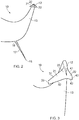
- FIG. 6 A second example, which does not form part of the invention, is shown in figure 6 , in which the first wing tip device element 13 is not twisted. Similar reference numerals are used to denote similar parts but numbered in the 100 series.
- the first wing tip device 110 has an inboard portion 121 with an inboard extent 133, and a first vertex 135 defined between the lower aerodynamic surface 136 of the inboard portion 121 and the upper aerodynamic surface 114 of the first wing tip device element 113.
- the first wing tip device 110 has an outboard portion 122 with an outboard extent 143, and a second vertex 145 defined between the lower aerodynamic surface 146 of the outboard portion 122 and the lower aerodynamic surface 115 of the first wing tip device element 113.
- the tip end 112 of the first wing tip device element 113 is the outermost spanwise extent of the first wing tip device element 113, such that the spanwise extent 55 of the wing is outboard of the first wing tip device element 113 and at the outboard extent 143 of the outboard portion 122.
- Figure 7 shows a third example in which similar reference numerals are used to denote similar parts but numbered in the 200 series.
- the second wing tip device element 220 is not planar and the first vertex 235 and second vertex 245 have angles of approximately 120 degrees, such that the first vertex 235 and the second vertex 245 are not complementary angles.
- the first wing tip device element includes an uplet 313 attached to a wing at a root end 311, and a downlet 317 attached at a root end 316 between the root end 311 of the uplet 313 and tip end 312 of the uplet 313.
- a second wing tip device element 320 having an inboard portion 321 and an outboard portion 322, is attached to the tip end 312 of the uplet 313.
- the second wing tip device 320 is substantially the same as in previous examples, having an inboard portion 321 with an inboard extent 333, and an outboard portion 322 with an outboard extent 343.
- a first vertex 335 is defined between the lower aerodynamic surface 336 of the inboard portion 321 and the upper aerodynamic surface 314 of the uplet 313, and a second vertex 345 is defined between the lower aerodynamic surface 346 of the outboard portion 322 and the lower aerodynamic surface 315 of the uplet 313.
- a second wing tip device element 360 is also coupled to the tip end 318 of the downlet 317 of the first wing tip device element 310.
- the additional second wing tip device element 360 is substantially the same as in previous examples, having an inboard portion 361 extending inboard from the tip end 318 of the downlet 317, and an outboard portion 362 extending outboard from the tip end 318 of the downlet of the first wing tip device element.
- the first vertex 375 is defined between the lower aerodynamic surface 352 of the downlet 317 and the lower aerodynamic surface 376 of the inboard portion 361 of the second wing tip device element 360
- the second vertex 385 is defined between the upper aerodynamic surface 351 of the downlet 317 and the lower aerodynamic surface 386 of the outboard portion 362 of the second wing tip device element 360.
- Figure 9 shows a fifth example, which does not form part of the invention, of the wing tip device 10 in which similar reference numerals are used to denote similar parts but numbered in the 400 series.
- the first wing tip device element is a split wing tip having an uplet 413 and downlet 417 as in the fourth example, however the wing tip device 410 only includes one second wing tip device element, which is attached to the tip end 418 of the downlet 417.
- the second wing tip device element 460 has an inboard portion 461 extending from the tip end 418 of the downlet 417 to an inboard extent 473, and an outboard portion 462 extending from the tip end 418 of the downlet 417 to an outboard extent 483.
- the inboard portion 461 has an upper aerodynamic surface 477 a lower aerodynamic surface 476 and a first vertex 475 defined between the lower aerodynamic surface 476 of the inboard portion 461 and the lower aerodynamic surface 452 of the downlet 417.
- the outboard portion 462 has an upper aerodynamic surface 487, a lower aerodynamic surface 486, and a second vertex 485 defined between the lower aerodynamic surface 486 of the outboard portion 462 and the upper aerodynamic surface 451 of the downlet 417.
- Figure 10 shows a sixth example, which does not form part of the invention, of the wing tip device 10 in which similar reference numerals are used to denote similar parts but numbered in the 500 series.
- the first wing tip device element 513 is a winglet having a substantially planar portion attached to a non-planar wing tip extension.
- the first wing tip device element 513 has a second wing tip device element attached to the tip end 512 of the first wing tip device element.
- the second wing tip device element has an inboard portion 521 and an outboard portion 522, as in previous examples.
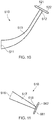
- Figure 11 shows a seventh example, which does not form part of the invention, of the wing tip device 10 in which similar reference numerals are used to denote similar parts but numbered in the 600 series.
- the wing tip device 613 is a downlet for attaching to the uplet of a split winglet.
- the first wing tip device element 613 has an inboard portion 621 and an outboard portion 622, as in previous examples.
- Figure 12 shows an eighth example, which does not form part of the invention, of the wing tip device 10 in which similar reference numerals are used to denote similar parts but numbered in the 700 series.
- the first wing tip device element 713 is a winglet having a substantially planar portion attached to a non-planar wing tip extension.
- the first wing tip device element 713 has a the second wing tip device element with only an inboard portion 721 attached to the tip end 712 of the first wing tip device element 713.
- the inboard portion 721 functions similarly to inboard portions described in relation to previous examples, and it will be clear to the skilled person that the second wing tip device could be appropriately combined with many other types of first wing tip device elements, such as those mentioned in the previous examples.
- Figure 13 shows a ninth example, which does not form part of the invention, of the wing tip device 10 in which similar reference numerals are used to denote similar parts but numbered in the 800 series.
- the second wing tip device element of the wing tip device 810 only has an outboard portion 822 attached to the tip end 812 of the first wing tip device element 813.
- the outboard portion 822 functions similarly to outboard portions described in relation to previous examples, and it will be clear to the skilled person that the second wing tip device could be appropriately combined with many other types of first wing tip device elements, such as those mentioned in the previous examples.
- figures 2 to 5 show an example in which the first wing tip device is twisted, although any of the described examples may include a twisted first wing tip device element.
- Figure 7 shows an example in which the second wing tip device element 220 is not planar, such that the inboard portion 221 and outboard portion 222 do not form a complimentary angle. It will be understood that this may appropriately apply to any of the other examples.
- wing tip devices described in each of the above examples may be fitted, or retro-fitted, to the outboard end of an aircraft having either no wing tip device (in the case of 'fitting') or as a replacement for an existing wing tip device (in the case of 'retro-fitting').
- the wing tip device may be fitted, or retro-fitted, to another wing tip device, for instance in the case of a downlet fitted to the lower aerodynamic surface of an uplet.
Landscapes
- Engineering & Computer Science (AREA)
- Aviation & Aerospace Engineering (AREA)
- Mechanical Engineering (AREA)
- Physics & Mathematics (AREA)
- Fluid Mechanics (AREA)
- Structures Of Non-Positive Displacement Pumps (AREA)
- Toys (AREA)
Description
- The present invention relates to a wing tip device, an aircraft wing including the wing tip device and a method of fitting, or retro-fitting, a wing tip device to an aircraft wing.
- It is well-known that increasing the wing span of an aircraft, or including wing tip devices, such as winglets, wing tip fences and raked wing tips, that increase the effective wing span without significantly increasing the wing span, can improve aerodynamic performance, for example by controlling the development of wing tip vortices and reducing induced drag (i.e. drag due to the development of lift).
- Due to twist of a wing tip device, the wing tip vortices may be located inboard of the outboard-most extent of the wing tip device. This can cause an increase in induced drag. It would be beneficial to locate the wing tip vortices as far outboard as possible with due regard to the wing span and winglet size.
WO2013/007396 A1 describes ancillary wing parts arranged on a wingtip device so as to reduce the aerodynamic drag of the overall wing tip device and reduce the loads acting on the overall wingtip device.DE3800110 A1 describes a method of reducing the induced drag on the wing tips of aircraft, each wing tip comprising an inboard and an outboard portion.US7644892 B1 describes a winglet comprising a helical portion.RU2264328 C1 US2011/024573 A1 describes a winglet having an inboard extending portion.EP3296202 A1 describes a tilt-rotor aircraft having wing extensions with winglets having various protrusions.US6474604 B1 describes a continuous wing design. - According to an aspect of the invention, there is provided a wing tip device for attaching to an aircraft. The wing tip device comprising a first wing tip device element having a root end and a tip end, a second wing tip device element coupled to the tip end of the first wing tip device element, wherein the second wing tip device element has an inboard portion extending inboard from the tip end of the first wing tip device element and/or an outboard portion extending outboard from the tip end of the first wing tip device element, when viewed in the wing planform direction. The first wing tip device element includes an outboard spanwise extent, when viewed in the wing planform direction, wherein at least a trailing edge of the tip end of the first wing tip device element is inboard of the outboard spanwise extent. The outboard portion of the second wing tip device extends up to the outboard spanwise extent.
- The wing planform direction is the direction normal to the plane of the wing.
- By providing the second wing tip device element having the outboard portion at the tip end of the first wing tip device element, the wing tip vortices can be better controlled and induced drag can be reduced. The outboard extending portion of the second wing tip device element can move the tip vortex outboard, thereby reducing induced drag. The inboard extending portion of the second wing tip device element provides a counter-rotating lifting surface, about the tip of the first wing tip device element, which can cancel out a portion of the wing loading.
- By extending the outboard portion up to the outboard spanwise extent, the induced drag can be reduced with little increase in tip loading and no increase in wingspan.
- According to a second aspect of the invention, there is provided an aircraft wing comprising a wing root end and a wing tip and, and a wing tip device according to the first aspect attached to the wing tip end.
- According to a third aspect, there is provided a fixed wing aircraft, comprising a wing according to the second aspect.
- According to a further aspect, there is provided a method of fitting, or retro fitting, a wing tip device to an aircraft wing, the method comprising fixing a wing tip device in accordance with the first aspect of the invention to the tip end of a wing.
- The wing tip device may have a first vertex between the first wing tip device element and the inboard portion of the second wing tip device element.
- The wing tip device may have a second vertex between the first wing tip device element and the outboard portion of the second wing tip device element.
- The second wing tip device element may be substantially planar.
- The plane of the second wing tip device element may be oriented approximately normal to a cant angle of the tip end of the first wing tip device element.
- The first wing tip device element may be twisted between the root end of the first wing tip device element and the tip end of the first wing tip device element. The first wing tip device element may be twisted about an axis parallel to the wing planform direction so that the first wing tip device has a toe-out angle or a toe-in angle.
- The wetted area of the second wing tip device element may be less than 40% of the wetted area of the first wingtip device element, and may be less than 20% of the wetted area of the first wing tip device element.
- The wetted area of a device portion is the area of that device portion that is exposed to the external airflow.
- The wetted area of the inboard portion may be greater than the wetted area of the outboard portion.
- The second wing tip device element may extend aft, when viewed in the wing planform direction, of the tip of the first wing tip device element.
- In order to maximise the reduction in induced drag, the trailing edge of the second wing tip device element may be positioned at the outboard spanwise extent of the wing tip device.
- The inboard portion may have an aft swept region.
- The outboard portion may have an aft swept region.
- The tip end of the first wing tip device element may have a cant angle of at least 20 degrees.
- The first wing tip device element may be a non-planar wing tip extension, a winglet, a winglet having a substantially planar portion and a non-planar wing tip extension, a blended winglet, a split winglet having an uplet and a downlet, a downlet, or a raked wing tip.
- A non-planar wing tip extension is a tip extension that extends out of the plane of the wing to which it is attached. A winglet is a wing-like element that extends from the wing tip. A winglet may extend upwardly or downwardly from the wing tip. A winglet may be considered to be a particular example of a non-planar wing tip extension. A winglet may include a substantially planar portion joined to the wing tip by a non-planar wing tip extension portion, the non-planar wing tip extension portion having an increasing curvature of local dihedral in the outboard direction. A blended winglet is a type of winglet that included a substantially planar portion joined to the wing tip by a curved transition portion, the transition portion having a constant radius of curvature. A raked wing tip device is a substantially planar wing tip extension which does not extend substantially out of the plane of the wing but has a higher sweep angle at the tip. A split winglet includes a wing-like lifting surface projecting upwardly (an 'uplet') from the wing, and a wing-like lifting surface projecting downwardly (a 'downlet') from the wing.
- A winglet is a wing-like lifting surface projecting upwardly (an 'uplet') or downwardly (a 'downlet') from the wing. The first wing tip element may include both an uplet and a downlet, e.g. a split winglet.
- The first wing tip device may include an uplet and a downlet wherein the second wingtip device element is coupled to a tip end of the uplet or downlet or a plurality of the second wing tip device elements are coupled to the uplet and downlet respectively.
- A tip of the uplet and the tip of the downlet may be located at substantially the same spanwise location, when viewed in the wing planform direction.
- The spanwise extent of the wing of the third aspect of the invention in the ground shape is substantially equal to an airport compatibility gate limit.
- Embodiments of the invention will now be described with reference to the accompanying drawings, in which:
-
Figure 1 is a plan view of an aircraft; -
Figure 2 shows a perspective view of a wing tip device according to a first aspect of the invention; -
Figure 3 shows a planform view of the second wing tip device element attached to the first wing tip device element; -
Figure 4 shows a perspective view of the second wing tip device element attached to the first wing tip device element, in accordance with the present invention; -
Figure 5 shows a view along the longitudinal axis of the wing tip device according to the first example, in accordance with the present invention; -
Figure 6 shows a second example of the wing tip device, which does not form part of the invention; -
Figure 7 shows a third example of the wing tip device, which does not form part of the invention; -
Figure 8 shows a fourth example of the wing tip device, which does not form part of the invention, including a two second wing tip device elements coupled to respective uplets and downlets of a split winglet; -
Figure 9 shows a fifth example of the wing tip device, which does not form part of the invention, showing the second wing tip device element coupled to the downlet of a split winglet; -
Figure 10 shows a sixth example of the wing tip device, which does not form part of the invention, that is a winglet having a substantially planar portion and a non-planar wing tip extension; and -
Figure 11 shows a seventh example of a wing tip device, which does not form part of the invention, that is a downlet; -
Figure 12 shows an eighth example of a wing tip device, which does not form part of the invention, having a second wing tip device element having only an inboard portion; -
Figure 13 shows a ninth example of a wing tip device, which does not form part of the invention, having a second wing tip device element having only an outboard portion. -
Figure 1 shows an existing aircraft 1 with port and starboard fixedwings engines 9, afuselage 4 with anose end 5 and atail end 6, thetail end 6 including horizontal and vertical stabilising surfaces 7, 8. The aircraft 1 is a typical jet passenger transonic transport aircraft but the invention is applicable to a wide variety of fixed wing aircraft types, including commercial, military, passenger, cargo, jet, propeller, general aviation, etc. with any number of engines attached to the wings or fuselage. - Each
wing aircraft fuselage 4. At the tip end of eachwing 2. 3 is awing tip device 10 outboard of a main wing portion of thewing 3. Thewings - As the
wings wing tip device 10 of thestarboard wing 3 will be described in detail with reference tofigures 2 to 5 . - The
wing tip device 10 includes an upwardly extendingwinglet 13 extending between a root end 11, attached to a main wing portion of awing 3, and atip end 12 of the upwardlyextended winglet 13. Thewing tip device 10 is a split winglet, such that a downwardly extendingwinglet 17, extending from aroot end 18 to atip end 16, is attached to the upwardly extending winglet between the root end 11 of the upwardly extendingwinglet 13 and atip end 12 of the upwardly extendingwinglet 13. - In order to increase the effectiveness of the wing tip device, for example by controlling the development of wing tip vortices and reducing induced drag without significantly increasing the wing span, a second wing
tip device element 20, which in this embodiment is similar in shape to a wing tip fence, is attached to thetip 12 of the first wingtip device element 13. - The second wing
tip device element 20 has aninboard portion 21 extending inboard from thetip end 12 of the firstwing tip device 13. Theinboard portion 21 has aleading edge 31, a trailingedge 32, and aninboard extent 33 between leadingedge 31 and the trailingedge 32. - The second wing
tip device element 20 has anoutboard portion 22 extending outboard from thetip end 12 of the first wingtip device element 13. Theoutboard portion 22 has aleading edge 41, a trailingedge 42, and anoutboard extent 43 between theleading edge 41 and the trailing 42. - In the example shown in
figures 2 to 5 , theinboard extent 33 andoutboard extent 43 are planar sides of the second wingtip device element 20. Alternatively the leadingedge 31 and trailingedge 32 of theinboard portion 21 may meet to form a cusp, or smoothly contoured projection that forms the inboard extent, and the leadingedge 41 and trailingedge 42 of theoutboard portion 22 may meet to form a cusp, or smoothly contoured projection that forms the outboard extent. - The leading
edge 31 and trailingedge 32 of theinboard portion 21, and leadingedge 41 and trailingedge 42 of theoutboard portion 22 are each swept aft relative to the longitudinal direction of the aircraft. The aircraft longitudinal direction is the direction along an axis between the nose end and tail end of the aircraft fuselage. - The leading
edge 31 of the inboard portion has a sweep angle of approximately 35 degrees, although may preferably have a sweep angle between 20 degrees and 60 degrees. The leadingedge 41 of the outboard portion has a sweep angle of approximately 60 degrees, although may preferably have a sweep angle of between 30 degrees and 50 degrees. The leadingedges - The sweep angle of the trailing
edges outboard portions leading edges tip end 12 of the firstwing tip device 13, and the chord length of the outboard portion decreases as it extends outboard from thetip end 12 of the firstwing tip device 13. The trailingedges tip end 12 of the firstwing tip device 13. The juncture is smoothly contoured although alternatively the trailingedges - The
tip end 12 of the first wingtip device element 13 projects upwardly, with respect to the plane of thewing 3, above the secondwing tip device 20 and is contoured into the upperaerodynamic surfaces outboard portions tip device element 13 is located forward of theleading edges tip device element 20. - The wetted area of the
inboard portion 21 is approximately 3 times greater than the wetted area of theoutboard portion 22, and is preferably between 0.7 and 5 times greater than the wetted area of theoutboard portion 22. - The first wing tip device element twists from its root end 11 to its
tip end 12, such that thetip end 12 of the firstwing tip device 13 is inboard of an outboardspanwise extent 50 of the first wingtip device element 13 shown infigure 4 . As a result, theoutboard extent 43 of theoutboard portion 22 can be extended up to the spanwise location of the outboardspanwise extent 50 of the first wingtip device element 13, without increasing thespanwise extent 55 of thewing 3. - As shown in
figure 5 , theinboard portion 21 and first wingtip device element 13 define afirst vertex 35 between the loweraerodynamic surface 36 of theinboard portion 21 and the upperaerodynamic surface 14 of the first wingtip device element 13. Asecond vertex 45 is defined between theoutboard portion 22 and the first wingtip device element 13, between the loweraerodynamic surface 46 of theoutboard portion 22 and the loweraerodynamic surface 15 of the first wingtip device element 13. - A second example, which does not form part of the invention, is shown in
figure 6 , in which the first wingtip device element 13 is not twisted. Similar reference numerals are used to denote similar parts but numbered in the 100 series. - The first
wing tip device 110 has aninboard portion 121 with aninboard extent 133, and afirst vertex 135 defined between the loweraerodynamic surface 136 of theinboard portion 121 and the upperaerodynamic surface 114 of the first wingtip device element 113. The firstwing tip device 110 has anoutboard portion 122 with anoutboard extent 143, and asecond vertex 145 defined between the loweraerodynamic surface 146 of theoutboard portion 122 and the loweraerodynamic surface 115 of the first wingtip device element 113. In this example, thetip end 112 of the first wingtip device element 113 is the outermost spanwise extent of the first wingtip device element 113, such that thespanwise extent 55 of the wing is outboard of the first wingtip device element 113 and at theoutboard extent 143 of theoutboard portion 122. -
Figure 7 shows a third example in which similar reference numerals are used to denote similar parts but numbered in the 200 series. - In this third example, which does not form part of the invention, the second wing tip device element 220 is not planar and the
first vertex 235 andsecond vertex 245 have angles of approximately 120 degrees, such that thefirst vertex 235 and thesecond vertex 245 are not complementary angles. - In a fourth example, which does not form part of the invention, shown in
figure 8 similar reference numerals are used to denote similar parts but numbered in the 300 series. - The first wing tip device element includes an
uplet 313 attached to a wing at aroot end 311, and adownlet 317 attached at aroot end 316 between theroot end 311 of theuplet 313 and tip end 312 of theuplet 313. A second wing tip device element 320, having aninboard portion 321 and anoutboard portion 322, is attached to thetip end 312 of theuplet 313. - The second wing tip device 320 is substantially the same as in previous examples, having an
inboard portion 321 with aninboard extent 333, and anoutboard portion 322 with anoutboard extent 343. A first vertex 335 is defined between the lower aerodynamic surface 336 of theinboard portion 321 and the upperaerodynamic surface 314 of theuplet 313, and a second vertex 345 is defined between the lower aerodynamic surface 346 of theoutboard portion 322 and the loweraerodynamic surface 315 of theuplet 313. - A second wing tip device element 360 is also coupled to the
tip end 318 of thedownlet 317 of the first wingtip device element 310. The additional second wing tip device element 360 is substantially the same as in previous examples, having aninboard portion 361 extending inboard from thetip end 318 of thedownlet 317, and anoutboard portion 362 extending outboard from thetip end 318 of the downlet of the first wing tip device element. Thefirst vertex 375 is defined between the loweraerodynamic surface 352 of thedownlet 317 and the loweraerodynamic surface 376 of theinboard portion 361 of the second wing tip device element 360, and thesecond vertex 385 is defined between the upperaerodynamic surface 351 of thedownlet 317 and the loweraerodynamic surface 386 of theoutboard portion 362 of the second wing tip device element 360. -
Figure 9 shows a fifth example, which does not form part of the invention, of thewing tip device 10 in which similar reference numerals are used to denote similar parts but numbered in the 400 series. - In this fifth example, the first wing tip device element is a split wing tip having an
uplet 413 anddownlet 417 as in the fourth example, however the wing tip device 410 only includes one second wing tip device element, which is attached to thetip end 418 of thedownlet 417. The second wing tip device element 460 has aninboard portion 461 extending from thetip end 418 of thedownlet 417 to aninboard extent 473, and anoutboard portion 462 extending from thetip end 418 of thedownlet 417 to anoutboard extent 483. Theinboard portion 461 has an upper aerodynamic surface 477 a loweraerodynamic surface 476 and a first vertex 475 defined between the loweraerodynamic surface 476 of theinboard portion 461 and the loweraerodynamic surface 452 of thedownlet 417. Theoutboard portion 462 has an upperaerodynamic surface 487, a loweraerodynamic surface 486, and a second vertex 485 defined between the loweraerodynamic surface 486 of theoutboard portion 462 and the upperaerodynamic surface 451 of thedownlet 417. -
Figure 10 shows a sixth example, which does not form part of the invention, of thewing tip device 10 in which similar reference numerals are used to denote similar parts but numbered in the 500 series. - In this sixth example, the first wing
tip device element 513 is a winglet having a substantially planar portion attached to a non-planar wing tip extension. The first wingtip device element 513 has a second wing tip device element attached to thetip end 512 of the first wing tip device element. The second wing tip device element has aninboard portion 521 and anoutboard portion 522, as in previous examples. -
Figure 11 shows a seventh example, which does not form part of the invention, of thewing tip device 10 in which similar reference numerals are used to denote similar parts but numbered in the 600 series. - In this seventh example, the wing tip device 613 is a downlet for attaching to the uplet of a split winglet. The first wing tip device element 613 has an inboard portion 621 and an outboard portion 622, as in previous examples.
-
Figure 12 shows an eighth example, which does not form part of the invention, of thewing tip device 10 in which similar reference numerals are used to denote similar parts but numbered in the 700 series. - In this eighth example, the first wing
tip device element 713 is a winglet having a substantially planar portion attached to a non-planar wing tip extension. The first wingtip device element 713 has a the second wing tip device element with only aninboard portion 721 attached to thetip end 712 of the first wingtip device element 713. Theinboard portion 721 functions similarly to inboard portions described in relation to previous examples, and it will be clear to the skilled person that the second wing tip device could be appropriately combined with many other types of first wing tip device elements, such as those mentioned in the previous examples. -
Figure 13 shows a ninth example, which does not form part of the invention, of thewing tip device 10 in which similar reference numerals are used to denote similar parts but numbered in the 800 series. - In this ninth example, the second wing tip device element of the
wing tip device 810 only has anoutboard portion 822 attached to thetip end 812 of the first wingtip device element 813. Theoutboard portion 822 functions similarly to outboard portions described in relation to previous examples, and it will be clear to the skilled person that the second wing tip device could be appropriately combined with many other types of first wing tip device elements, such as those mentioned in the previous examples. - It will be clear to the skilled person that many of the features described in relation to each example can be appropriately combined with the features of other examples.
- For instance,
figures 2 to 5 show an example in which the first wing tip device is twisted, although any of the described examples may include a twisted first wing tip device element. -
Figure 7 shows an example in which the second wing tip device element 220 is not planar, such that theinboard portion 221 andoutboard portion 222 do not form a complimentary angle. It will be understood that this may appropriately apply to any of the other examples. - The wing tip devices described in each of the above examples may be fitted, or retro-fitted, to the outboard end of an aircraft having either no wing tip device (in the case of 'fitting') or as a replacement for an existing wing tip device (in the case of 'retro-fitting'). In some cases it will be clear that the wing tip device may be fitted, or retro-fitted, to another wing tip device, for instance in the case of a downlet fitted to the lower aerodynamic surface of an uplet.
- Where the word 'or' appears this is to be construed to mean 'and/or' such that items referred to are not necessarily mutually exclusive and may be used in any appropriate combination.
- Although the invention has been described above with reference to one or more preferred embodiments, it will be appreciated that various changes or modifications may be made without departing from the scope of the invention as defined in the appended claims.
Claims (15)
- A wing tip device (10) for attaching to an aircraft wing (2, 3) comprising:a first wing tip device element (13) having a root end and a tip end (12);a second wing tip device element (20) coupled to the tip end (12) of the first wing tip device element (13);wherein the second wing tip device element (20) has an inboard portion (21) andan outboard portion (22), wherein the inboard portion (21) extends inboard from the tip end (12) of the first wing tip device element (13) and the outboard portion (22) extends outboard from the tip end (12) of the first wing tip device element (13), when viewed in the wing planform direction,wherein the first wing tip device element (13) includes an outboard spanwise extent (55), when viewed in the wing planform direction, wherein at least a trailing edge portion of the tip end (12) of the first wing tip device element (13) is inboard of the outboard spanwise extent (55); and characterised in that the outboard portion (22) of the second wing tip device element (20) extends up to the outboard spanwise extent (55).
- A wing tip device (10) according to claim 1, wherein the wing tip device (10) has a first vertex between the first wing tip device element (13) and the inboard portion (21) of the second wing tip device element (20).
- A wing tip device (10) according to claim 1 or claim 2, wherein the wing tip device (10) has a second vertex between the first wing tip device element (13) and the outboard portion (22) of the second wing tip device element (20).
- A wing tip device (10) according to any preceding claim, wherein the second wing tip device element is substantially planar.
- A wing tip device (10) according to claim 4, wherein the plane of the second wing tip device element (20) is oriented approximately normal to a cant angle at the tip end (12) of the first wing tip device element (13).
- A wing tip device (10) according to any preceding claim, wherein the first wing tip device element (13) is twisted between the root end (11) of the first wing tip device element (13) and the tip end (12) of the first wing tip device element (13);
preferably wherein the first wing tip device element is twisted about an axis parallel to the wing planform direction so that the first wing tip device has a toe-out angle. - A wing tip device (10) according to any preceding claim, wherein the wetted area of the second wing tip device element (20) is less than 40% of the wetted area of the first wing tip device element (13), and preferably less than 20% of the wetted area of the first wing tip device element (13).
- A wing tip device (10) according to any preceding claim, wherein the wetted area of the inboard portion (21) is greater than the wetted area of the outboard portion (22).
- A wing tip device (10) according to any preceding claim, wherein the second wing tip device element (20) extends aft, when viewed in the wing planform direction, of the tip of the first wing tip device element (13).
- A wing tip device (10) according to any preceding claim, wherein the outboard portion (22) and/or the inboard portion (21) has an aft swept region.
- A wing tip device (10) according to any preceding claim, wherein the tip end (12) of the first wing tip device element (13) has a cant angle of at least 20 degrees.
- A wing tip device (10) according to any preceding claim, wherein the first wing tip device element (13) is a non-planar wing tip extension, a winglet, a winglet having a substantially planar portion and a non-planar wing tip extension, a blended winglet, a split winglet having an uplet and a downlet, a downlet, or a raked wingtip.
- A wing tip device (10) according to any preceding claim, wherein the first wing tip device element (13) includes an uplet and a downlet, wherein the second wing tip device element (20) is coupled to a tip end of the uplet or downlet, or a plurality of the second wing tip device elements are coupled to the uplet and downlet respectively; preferably wherein a tip of the uplet and a tip of the downlet are located at substantially the same spanwise location, when viewed in the wing planform direction.
- An aircraft wing (2, 3) comprising a wing root end and a wing tip end, and a wing tip device according to any preceding claim attached to the wing tip end.
- A method of fitting, or retro-fitting, a wing tip device (10) to an aircraft wing, the method comprising fixing a wing tip device (10) in accordance with any one of claims 1 to 13 to the tip end of a wing (2, 3).
Applications Claiming Priority (1)
| Application Number | Priority Date | Filing Date | Title |
|---|---|---|---|
| GB1815386.6A GB2577303A (en) | 2018-09-21 | 2018-09-21 | A wing tip device |
Publications (2)
| Publication Number | Publication Date |
|---|---|
| EP3626608A1 EP3626608A1 (en) | 2020-03-25 |
| EP3626608B1 true EP3626608B1 (en) | 2021-10-27 |
Family
ID=64024082
Family Applications (1)
| Application Number | Title | Priority Date | Filing Date |
|---|---|---|---|
| EP19196614.2A Active EP3626608B1 (en) | 2018-09-21 | 2019-09-11 | A wing tip device |
Country Status (4)
| Country | Link |
|---|---|
| US (1) | US11345461B2 (en) |
| EP (1) | EP3626608B1 (en) |
| CN (1) | CN110937103A (en) |
| GB (1) | GB2577303A (en) |
Families Citing this family (1)
| Publication number | Priority date | Publication date | Assignee | Title |
|---|---|---|---|---|
| CN112829922B (en) * | 2021-02-08 | 2022-01-07 | 北京北航天宇长鹰无人机科技有限公司 | Unmanned plane |
Family Cites Families (16)
| Publication number | Priority date | Publication date | Assignee | Title |
|---|---|---|---|---|
| US2576981A (en) * | 1949-02-08 | 1951-12-04 | Vogt Richard | Twisted wing tip fin for airplanes |
| US3231038A (en) * | 1964-01-29 | 1966-01-25 | Douglas Aircraft Co Inc | Fixed wing ground effect craft |
| DE3800110A1 (en) * | 1988-01-05 | 1989-07-20 | Dieter Schmidt | Method for reducing the induced drag on aircraft |
| US5102068A (en) | 1991-02-25 | 1992-04-07 | Gratzer Louis B | Spiroid-tipped wing |
| USD363696S (en) * | 1993-06-23 | 1995-10-31 | The Boeing Company | Large airplane with nonplanar wing |
| US6474604B1 (en) | 1999-04-12 | 2002-11-05 | Jerry E. Carlow | Mobius-like joining structure for fluid dynamic foils |
| RU2264328C1 (en) * | 2004-04-27 | 2005-11-20 | Открытое акционерное общество "Туполев" (ОАО "Туполев") | Flying vehicle wing tip |
| GB0518755D0 (en) | 2005-09-14 | 2005-10-19 | Airbus Uk Ltd | Wing tip device |
| US7644892B1 (en) | 2006-07-06 | 2010-01-12 | Alford Jr Lionel D | Blended winglet |
| GB0711942D0 (en) * | 2007-06-21 | 2007-08-01 | Airbus Uk Ltd | Winglet |
| US20110024573A1 (en) * | 2009-05-06 | 2011-02-03 | Quiet Wing Technologies, Inc. | Extended winglet with load balancing characteristics |
| GB0913602D0 (en) * | 2009-08-05 | 2009-09-16 | Qinetiq Ltd | Aircraft |
| GB201011843D0 (en) * | 2010-07-14 | 2010-09-01 | Airbus Operations Ltd | Wing tip device |
| DE102011107251A1 (en) | 2011-07-14 | 2013-01-17 | Airbus Operations Gmbh | Wing tail of a wing and a wing with such wing tail |
| DE102014112827B3 (en) * | 2014-09-05 | 2016-02-11 | Airbus Defence and Space GmbH | Aircraft with C-shaped wings and movable top surfaces |
| US10266252B2 (en) | 2016-09-19 | 2019-04-23 | Bell Helicopter Textron Inc. | Wing extension winglets for tiltrotor aircraft |
-
2018
- 2018-09-21 GB GB1815386.6A patent/GB2577303A/en not_active Withdrawn
-
2019
- 2019-09-05 US US16/561,227 patent/US11345461B2/en active Active
- 2019-09-11 EP EP19196614.2A patent/EP3626608B1/en active Active
- 2019-09-19 CN CN201910884878.9A patent/CN110937103A/en active Pending
Also Published As
| Publication number | Publication date |
|---|---|
| CN110937103A (en) | 2020-03-31 |
| GB201815386D0 (en) | 2018-11-07 |
| US11345461B2 (en) | 2022-05-31 |
| US20200094940A1 (en) | 2020-03-26 |
| EP3626608A1 (en) | 2020-03-25 |
| GB2577303A (en) | 2020-03-25 |
Similar Documents
| Publication | Publication Date | Title |
|---|---|---|
| US9637226B2 (en) | Split winglet system | |
| EP1493660B2 (en) | Efficient wing tip devices and methods for incorporating such devices into existing wing designs | |
| EP2303685B1 (en) | Curved wing tip | |
| EP2610169B1 (en) | Wing tip device | |
| CA2291275C (en) | Blunt-leading-edge raked wingtips | |
| US7988100B2 (en) | Wing tip device | |
| US10625847B2 (en) | Split winglet | |
| US10933970B2 (en) | Aircraft with strut-braced wing system | |
| US20070262205A1 (en) | Retractable multiple winglet | |
| EP3626609B1 (en) | A wing tip device | |
| EP3626608B1 (en) | A wing tip device | |
| KR102669013B1 (en) | An aircraft wing and wing tip device |
Legal Events
| Date | Code | Title | Description |
|---|---|---|---|
| PUAI | Public reference made under article 153(3) epc to a published international application that has entered the european phase |
Free format text: ORIGINAL CODE: 0009012 |
|
| STAA | Information on the status of an ep patent application or granted ep patent |
Free format text: STATUS: THE APPLICATION HAS BEEN PUBLISHED |
|
| AK | Designated contracting states |
Kind code of ref document: A1 Designated state(s): AL AT BE BG CH CY CZ DE DK EE ES FI FR GB GR HR HU IE IS IT LI LT LU LV MC MK MT NL NO PL PT RO RS SE SI SK SM TR |
|
| AX | Request for extension of the european patent |
Extension state: BA ME |
|
| STAA | Information on the status of an ep patent application or granted ep patent |
Free format text: STATUS: REQUEST FOR EXAMINATION WAS MADE |
|
| 17P | Request for examination filed |
Effective date: 20200922 |
|
| RBV | Designated contracting states (corrected) |
Designated state(s): AL AT BE BG CH CY CZ DE DK EE ES FI FR GB GR HR HU IE IS IT LI LT LU LV MC MK MT NL NO PL PT RO RS SE SI SK SM TR |
|
| GRAP | Despatch of communication of intention to grant a patent |
Free format text: ORIGINAL CODE: EPIDOSNIGR1 |
|
| STAA | Information on the status of an ep patent application or granted ep patent |
Free format text: STATUS: GRANT OF PATENT IS INTENDED |
|
| INTG | Intention to grant announced |
Effective date: 20210112 |
|
| GRAJ | Information related to disapproval of communication of intention to grant by the applicant or resumption of examination proceedings by the epo deleted |
Free format text: ORIGINAL CODE: EPIDOSDIGR1 |
|
| STAA | Information on the status of an ep patent application or granted ep patent |
Free format text: STATUS: REQUEST FOR EXAMINATION WAS MADE |
|
| GRAP | Despatch of communication of intention to grant a patent |
Free format text: ORIGINAL CODE: EPIDOSNIGR1 |
|
| STAA | Information on the status of an ep patent application or granted ep patent |
Free format text: STATUS: GRANT OF PATENT IS INTENDED |
|
| INTC | Intention to grant announced (deleted) | ||
| INTG | Intention to grant announced |
Effective date: 20210419 |
|
| GRAS | Grant fee paid |
Free format text: ORIGINAL CODE: EPIDOSNIGR3 |
|
| GRAA | (expected) grant |
Free format text: ORIGINAL CODE: 0009210 |
|
| STAA | Information on the status of an ep patent application or granted ep patent |
Free format text: STATUS: THE PATENT HAS BEEN GRANTED |
|
| AK | Designated contracting states |
Kind code of ref document: B1 Designated state(s): AL AT BE BG CH CY CZ DE DK EE ES FI FR GB GR HR HU IE IS IT LI LT LU LV MC MK MT NL NO PL PT RO RS SE SI SK SM TR |
|
| REG | Reference to a national code |
Ref country code: GB Ref legal event code: FG4D |
|
| REG | Reference to a national code |
Ref country code: CH Ref legal event code: EP |
|
| REG | Reference to a national code |
Ref country code: AT Ref legal event code: REF Ref document number: 1441563 Country of ref document: AT Kind code of ref document: T Effective date: 20211115 |
|
| REG | Reference to a national code |
Ref country code: DE Ref legal event code: R096 Ref document number: 602019008653 Country of ref document: DE |
|
| REG | Reference to a national code |
Ref country code: IE Ref legal event code: FG4D |
|
| REG | Reference to a national code |
Ref country code: LT Ref legal event code: MG9D |
|
| REG | Reference to a national code |
Ref country code: NL Ref legal event code: MP Effective date: 20211027 |
|
| REG | Reference to a national code |
Ref country code: AT Ref legal event code: MK05 Ref document number: 1441563 Country of ref document: AT Kind code of ref document: T Effective date: 20211027 |
|
| PG25 | Lapsed in a contracting state [announced via postgrant information from national office to epo] |
Ref country code: RS Free format text: LAPSE BECAUSE OF FAILURE TO SUBMIT A TRANSLATION OF THE DESCRIPTION OR TO PAY THE FEE WITHIN THE PRESCRIBED TIME-LIMIT Effective date: 20211027 Ref country code: LT Free format text: LAPSE BECAUSE OF FAILURE TO SUBMIT A TRANSLATION OF THE DESCRIPTION OR TO PAY THE FEE WITHIN THE PRESCRIBED TIME-LIMIT Effective date: 20211027 Ref country code: FI Free format text: LAPSE BECAUSE OF FAILURE TO SUBMIT A TRANSLATION OF THE DESCRIPTION OR TO PAY THE FEE WITHIN THE PRESCRIBED TIME-LIMIT Effective date: 20211027 Ref country code: BG Free format text: LAPSE BECAUSE OF FAILURE TO SUBMIT A TRANSLATION OF THE DESCRIPTION OR TO PAY THE FEE WITHIN THE PRESCRIBED TIME-LIMIT Effective date: 20220127 Ref country code: AT Free format text: LAPSE BECAUSE OF FAILURE TO SUBMIT A TRANSLATION OF THE DESCRIPTION OR TO PAY THE FEE WITHIN THE PRESCRIBED TIME-LIMIT Effective date: 20211027 |
|
| PG25 | Lapsed in a contracting state [announced via postgrant information from national office to epo] |
Ref country code: IS Free format text: LAPSE BECAUSE OF FAILURE TO SUBMIT A TRANSLATION OF THE DESCRIPTION OR TO PAY THE FEE WITHIN THE PRESCRIBED TIME-LIMIT Effective date: 20220227 Ref country code: SE Free format text: LAPSE BECAUSE OF FAILURE TO SUBMIT A TRANSLATION OF THE DESCRIPTION OR TO PAY THE FEE WITHIN THE PRESCRIBED TIME-LIMIT Effective date: 20211027 Ref country code: PT Free format text: LAPSE BECAUSE OF FAILURE TO SUBMIT A TRANSLATION OF THE DESCRIPTION OR TO PAY THE FEE WITHIN THE PRESCRIBED TIME-LIMIT Effective date: 20220228 Ref country code: PL Free format text: LAPSE BECAUSE OF FAILURE TO SUBMIT A TRANSLATION OF THE DESCRIPTION OR TO PAY THE FEE WITHIN THE PRESCRIBED TIME-LIMIT Effective date: 20211027 Ref country code: NO Free format text: LAPSE BECAUSE OF FAILURE TO SUBMIT A TRANSLATION OF THE DESCRIPTION OR TO PAY THE FEE WITHIN THE PRESCRIBED TIME-LIMIT Effective date: 20220127 Ref country code: NL Free format text: LAPSE BECAUSE OF FAILURE TO SUBMIT A TRANSLATION OF THE DESCRIPTION OR TO PAY THE FEE WITHIN THE PRESCRIBED TIME-LIMIT Effective date: 20211027 Ref country code: LV Free format text: LAPSE BECAUSE OF FAILURE TO SUBMIT A TRANSLATION OF THE DESCRIPTION OR TO PAY THE FEE WITHIN THE PRESCRIBED TIME-LIMIT Effective date: 20211027 Ref country code: HR Free format text: LAPSE BECAUSE OF FAILURE TO SUBMIT A TRANSLATION OF THE DESCRIPTION OR TO PAY THE FEE WITHIN THE PRESCRIBED TIME-LIMIT Effective date: 20211027 Ref country code: GR Free format text: LAPSE BECAUSE OF FAILURE TO SUBMIT A TRANSLATION OF THE DESCRIPTION OR TO PAY THE FEE WITHIN THE PRESCRIBED TIME-LIMIT Effective date: 20220128 Ref country code: ES Free format text: LAPSE BECAUSE OF FAILURE TO SUBMIT A TRANSLATION OF THE DESCRIPTION OR TO PAY THE FEE WITHIN THE PRESCRIBED TIME-LIMIT Effective date: 20211027 |
|
| REG | Reference to a national code |
Ref country code: DE Ref legal event code: R097 Ref document number: 602019008653 Country of ref document: DE |
|
| PG25 | Lapsed in a contracting state [announced via postgrant information from national office to epo] |
Ref country code: SM Free format text: LAPSE BECAUSE OF FAILURE TO SUBMIT A TRANSLATION OF THE DESCRIPTION OR TO PAY THE FEE WITHIN THE PRESCRIBED TIME-LIMIT Effective date: 20211027 Ref country code: SK Free format text: LAPSE BECAUSE OF FAILURE TO SUBMIT A TRANSLATION OF THE DESCRIPTION OR TO PAY THE FEE WITHIN THE PRESCRIBED TIME-LIMIT Effective date: 20211027 Ref country code: RO Free format text: LAPSE BECAUSE OF FAILURE TO SUBMIT A TRANSLATION OF THE DESCRIPTION OR TO PAY THE FEE WITHIN THE PRESCRIBED TIME-LIMIT Effective date: 20211027 Ref country code: EE Free format text: LAPSE BECAUSE OF FAILURE TO SUBMIT A TRANSLATION OF THE DESCRIPTION OR TO PAY THE FEE WITHIN THE PRESCRIBED TIME-LIMIT Effective date: 20211027 Ref country code: DK Free format text: LAPSE BECAUSE OF FAILURE TO SUBMIT A TRANSLATION OF THE DESCRIPTION OR TO PAY THE FEE WITHIN THE PRESCRIBED TIME-LIMIT Effective date: 20211027 Ref country code: CZ Free format text: LAPSE BECAUSE OF FAILURE TO SUBMIT A TRANSLATION OF THE DESCRIPTION OR TO PAY THE FEE WITHIN THE PRESCRIBED TIME-LIMIT Effective date: 20211027 |
|
| PLBE | No opposition filed within time limit |
Free format text: ORIGINAL CODE: 0009261 |
|
| STAA | Information on the status of an ep patent application or granted ep patent |
Free format text: STATUS: NO OPPOSITION FILED WITHIN TIME LIMIT |
|
| 26N | No opposition filed |
Effective date: 20220728 |
|
| PG25 | Lapsed in a contracting state [announced via postgrant information from national office to epo] |
Ref country code: AL Free format text: LAPSE BECAUSE OF FAILURE TO SUBMIT A TRANSLATION OF THE DESCRIPTION OR TO PAY THE FEE WITHIN THE PRESCRIBED TIME-LIMIT Effective date: 20211027 |
|
| PG25 | Lapsed in a contracting state [announced via postgrant information from national office to epo] |
Ref country code: SI Free format text: LAPSE BECAUSE OF FAILURE TO SUBMIT A TRANSLATION OF THE DESCRIPTION OR TO PAY THE FEE WITHIN THE PRESCRIBED TIME-LIMIT Effective date: 20211027 |
|
| PG25 | Lapsed in a contracting state [announced via postgrant information from national office to epo] |
Ref country code: MC Free format text: LAPSE BECAUSE OF FAILURE TO SUBMIT A TRANSLATION OF THE DESCRIPTION OR TO PAY THE FEE WITHIN THE PRESCRIBED TIME-LIMIT Effective date: 20211027 |
|
| REG | Reference to a national code |
Ref country code: CH Ref legal event code: PL |
|
| REG | Reference to a national code |
Ref country code: BE Ref legal event code: MM Effective date: 20220930 |
|
| PG25 | Lapsed in a contracting state [announced via postgrant information from national office to epo] |
Ref country code: IT Free format text: LAPSE BECAUSE OF FAILURE TO SUBMIT A TRANSLATION OF THE DESCRIPTION OR TO PAY THE FEE WITHIN THE PRESCRIBED TIME-LIMIT Effective date: 20211027 |
|
| PG25 | Lapsed in a contracting state [announced via postgrant information from national office to epo] |
Ref country code: LU Free format text: LAPSE BECAUSE OF NON-PAYMENT OF DUE FEES Effective date: 20220911 |
|
| PG25 | Lapsed in a contracting state [announced via postgrant information from national office to epo] |
Ref country code: LI Free format text: LAPSE BECAUSE OF NON-PAYMENT OF DUE FEES Effective date: 20220930 Ref country code: IE Free format text: LAPSE BECAUSE OF NON-PAYMENT OF DUE FEES Effective date: 20220911 Ref country code: CH Free format text: LAPSE BECAUSE OF NON-PAYMENT OF DUE FEES Effective date: 20220930 |
|
| PG25 | Lapsed in a contracting state [announced via postgrant information from national office to epo] |
Ref country code: BE Free format text: LAPSE BECAUSE OF NON-PAYMENT OF DUE FEES Effective date: 20220930 |
|
| PGFP | Annual fee paid to national office [announced via postgrant information from national office to epo] |
Ref country code: GB Payment date: 20230920 Year of fee payment: 5 |
|
| PGFP | Annual fee paid to national office [announced via postgrant information from national office to epo] |
Ref country code: FR Payment date: 20230928 Year of fee payment: 5 Ref country code: DE Payment date: 20230920 Year of fee payment: 5 |
|
| PG25 | Lapsed in a contracting state [announced via postgrant information from national office to epo] |
Ref country code: HU Free format text: LAPSE BECAUSE OF FAILURE TO SUBMIT A TRANSLATION OF THE DESCRIPTION OR TO PAY THE FEE WITHIN THE PRESCRIBED TIME-LIMIT; INVALID AB INITIO Effective date: 20190911 |
|
| PG25 | Lapsed in a contracting state [announced via postgrant information from national office to epo] |
Ref country code: CY Free format text: LAPSE BECAUSE OF FAILURE TO SUBMIT A TRANSLATION OF THE DESCRIPTION OR TO PAY THE FEE WITHIN THE PRESCRIBED TIME-LIMIT Effective date: 20211027 |
|
| PG25 | Lapsed in a contracting state [announced via postgrant information from national office to epo] |
Ref country code: MK Free format text: LAPSE BECAUSE OF FAILURE TO SUBMIT A TRANSLATION OF THE DESCRIPTION OR TO PAY THE FEE WITHIN THE PRESCRIBED TIME-LIMIT Effective date: 20211027 |