EP3626528A1 - Vehicle provided with an improved table - Google Patents
Vehicle provided with an improved table Download PDFInfo
- Publication number
- EP3626528A1 EP3626528A1 EP19198792.4A EP19198792A EP3626528A1 EP 3626528 A1 EP3626528 A1 EP 3626528A1 EP 19198792 A EP19198792 A EP 19198792A EP 3626528 A1 EP3626528 A1 EP 3626528A1
- Authority
- EP
- European Patent Office
- Prior art keywords
- wall
- dashboard
- side walls
- housing
- vehicle according
- Prior art date
- Legal status (The legal status is an assumption and is not a legal conclusion. Google has not performed a legal analysis and makes no representation as to the accuracy of the status listed.)
- Granted
Links
- 230000003068 static effect Effects 0.000 claims description 3
- 230000007246 mechanism Effects 0.000 description 6
- 238000000605 extraction Methods 0.000 description 2
- 238000005452 bending Methods 0.000 description 1
- 238000006243 chemical reaction Methods 0.000 description 1
- 230000000295 complement effect Effects 0.000 description 1
- 230000008878 coupling Effects 0.000 description 1
- 238000010168 coupling process Methods 0.000 description 1
- 238000005859 coupling reaction Methods 0.000 description 1
- 230000003247 decreasing effect Effects 0.000 description 1
- 230000000670 limiting effect Effects 0.000 description 1
- 230000000284 resting effect Effects 0.000 description 1
- 230000002441 reversible effect Effects 0.000 description 1
Images


Classifications
-
- B—PERFORMING OPERATIONS; TRANSPORTING
- B60—VEHICLES IN GENERAL
- B60N—SEATS SPECIALLY ADAPTED FOR VEHICLES; VEHICLE PASSENGER ACCOMMODATION NOT OTHERWISE PROVIDED FOR
- B60N3/00—Arrangements or adaptations of other passenger fittings, not otherwise provided for
- B60N3/001—Arrangements or adaptations of other passenger fittings, not otherwise provided for of tables or trays
- B60N3/002—Arrangements or adaptations of other passenger fittings, not otherwise provided for of tables or trays of trays
Definitions
- the invention relates to a vehicle, more in particular to a heavy vehicle, such as a truck, provided with an improved table.
- Heavy vehicles such as for example trucks, usually comprise support surfaces designed to allow the driver of the vehicle, when on a brake, to eat and/or lay use elements, such as a laptop.
- Said support planes are normally designed, in order to decrease the space taken up inside the cabin, as foldable tables housed in the dashboard and/or inside elements that are integral to the seat.
- these foldable tables comprise a first and a second half planes, which are connected to one another in a foldable manner and are arranged inside the dashboard over their entire extension along the side parallel to the extraction direction.
- the object of the invention is to fulfil the needs discussed above.
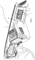
- Figure 1 shows the inside 1 of a vehicle (not shown) basically comprising a dashboard 2 configured to support and/or house a plurality of known elements and provided with an outer wall 2a with any shape, in the example shown herein a concave shape towards the inside 1 of the cabin of the vehicle.
- the dashboard 2 further comprises a housing 4 configured to house, on the inside, a table 3 according to the invention.
- the housing 4 can be defined by a pair of side walls 5 and 6, by a lower wall 7, by an upper wall 8 and by a bottom wall 9.
- Said walls 5, 6, 7, 8 and 9 are preferably manufactured as one single piece and, more preferably, they are manufactured as one single piece together with the outer wall 2a of the dashboard 2.
- the depth of the lower wall 7 inside the dashboard 2 preferably is greater than the depth of the upper wall 8 and the bottom wall 9 is inclined, preferably curved, in order to join the rear edges of said walls 7, 8. Furthermore, the housing 4 is open in the direction of the driver of the vehicle, at the front relative to the bottom wall 9.
- the bottom wall 9 extends inside the dashboard 2 with a depth of less than 100 mm.
- the table 3 comprises a first upper half plane 11 and a second lower half plane 12, each comprising a support wall 11a, 12a, a lower wall 11b, 12b, which is opposite the respective support wall 11a, 12a, and a pair of side walls 11c, 11d, 12c, 12d, which laterally join the support walls 11a, 12a and the lower walls 11b 12b.
- the support walls 11a, 12a, the lower walls 11b, 12b and the side walls 11c, 11d, 12c, 12d are preferably made of a plastic material and manufactured as one single piece.
- the half planes 11, 12 are connected to one another so as to define a first operating condition, in which the respective support walls 11a, 12a of the half planes 11, 12 face one another ( figures 2 to 11 ), and a second position, in which the support surfaces 11a, 12a are adjacent to one another ( figures 12 and 13 ) defining a support plane 10 that can be used by the user of the vehicle.
- This connection is advantageously obtained by means of a mechanical coupling, which is configured to allow the half planes 11, 12 to move relative to one another between the two operating conditions described above.
- This mechanical connection can preferably comprise a hinge 13 joining the two half planes 11, 12 along a transverse edge thereof so that the upper half plane 11 can rotate along a transverse edge of the lower half plane 12.
- one of the lower walls 11b, 12b of the two half planes 11, 12 has the same shape as the outer wall 2a of the dashboard 2 so that, when the table 3 is folded inside the housing 4, there is continuity between the lower wall 11b, 12b of the table 3 and the outer wall 2a of the dashboard 2.
- the lower wall 12b of the lower half plane 12 defines a shape that is complementary to the one of the outer wall 2a of the dashboard 2, whereas the lower wall 11b has a substantially flat shape.
- one of the two half planes 11, 12 is connected to the side walls 5 and 6 defining the housing 4 by means of respective cam connections 15, 16 arranged between the side walls 5 and 6 and the side walls 11c, 11d , 12c, 12d of one of the two half lanes 11, 12.
- the side walls 12c, 12d of the lower half-plane 12 are connected, by means of cam connections 15, 16, to the side walls 5 and 6 of the housing 4.
- the cam mechanism 15 comprises a first cam arrangement 17 configured to guide the movements of the half plane 12 so as to shift from a folded configuration to an open configuration - or vice versa - of the table 3.
- the cam arrangement 17 comprising a pin 18 carried by the lower half plane 12 and configured to slide in a guide 19 obtained in the side wall 6.
- the guide 19 defines the following path, from the bottom left corner to the top right corner of the side wall 6, comprising:
- first intermediate point 21a which can be reached by the pin 18 during its stroke inside the guide 19
- the intersection between the first curved portion 19b and the second straight portion 19c defines a second intermediate point 21b
- the intersection between the second curved portion 19c and the second straight portion 19d defines a third intermediate point 21c.
- the cam mechanism 15 further comprises a second cam arrangement 23 configured to define a static constraint between the half plane 12 and the side walls 5,6 when the table 3 is in an open configuration.
- the second cam arrangement 23 can comprise a pin 24 carried by the side wall 6 and a guide 25 obtained on the side wall 12c of the lower half plane 12.
- the horizontal guide 25 has a length such that and is positioned in such a way that, in combination with the cam arrangement 17, it allows the lower half plane 12 to be moved.
- the guide 25 defines a left end of stroke 25a and a right end of strike 25b.
- the cam connection 16 between the side wall 12d of the half plane 12 and the side wall 6 defining the housing 4 is mirror-like and equal to the cam connection 15 described above; therefore, it is not described for the sake of brevity.
- the table 3 works as follows.
- a first operating condition of the table 3 namely a folded condition, according to figures 2 and 3
- the half planes 11 and 12 are folded relative to one another, with the support walls 11a, 12a facing one another, and they are housed inside the housing 4 so that the lower wall 12b of the lower half plane 12 is a continuation of the outer wall 2a of the dashboard 2.
- the pin 18 is at the lower end of stroke 20a and the pin 24 is at the right end of stroke 25b.
- the driver of the vehicle can exert a force upon a lower portion of the wall 12b of the half plane 12, i.e. under the pin 24, so that the half planes 11, 12 rotate around the hinge created by the pin 24 and the pin 18 moves from the lower end of stroke 20a to the first intermediate position 21a along the first curved portion 19a.
- a third moving phase of the table 3 the driver of the vehicle can exert a force upon a lower portion of the wall 12b of the half plane 12, always under the pin 24, so that the half planes 11, 12 rotate around the hinge created by the pin 24 and the pin 18 moves from the second intermediate position 21b to the third intermediate position 21c along the second curved portion 19c.
- a fourth moving phase of the table 3 according to figures 10 and 11 , the driver of the vehicle applies a horizontal force aimed at pushing the half planes 11, 12 towards the inside of the housing 4.
- the pin 24 slides in the guide 25 from the right end of stroke 25b to an intermediate position between the latter and the left end of stroke and the pin 18 moves from the third intermediate position 21c to the upper end of stroke 20b along the second straight portion 19d.
- a fifth moving phase which is shown in figure 13
- the driver of the vehicle can overturn the half plane 11 relative to the half plane 12, causing it to rotate around the hinge 13 so that the support portions 11a, 12a define the support plane 10, as shown in figure 12 , which shows the second operating condition, namely the open condition, of the table 3.
- a weight applied on the support plane 10 is balanced by the reactions in the pins 18 and 24 relative to the respective guides.
- the table 3 creates a support plane 10 having an adequate extension with a minimum space taken up, in the table extraction direction, inside the dashboard 2.
- the space taken up inside the dashboard is less than 100 mm, whereas the length of the support plane 10, in the opening direction of the table 3, is approximately 350 mm.
- the cam mechanism 15, 16 described above does not require the support arms present in the prior art and, hence, has smaller dimensions and is more economic.
- the path optimized by the guides 19 and 25 allows the half planes 11, 12 to be pulled out of the housing 4, though taking up a minimum space inside the dashboard 2.
- the shape of the outer wall 2a of the dashboard 2 and, similarly, the shape of the lower wall 12b of the half plane 12 can be changed according to the needs.
- cam mechanisms 15, 16 can clearly be designed in a different manner, just like the cam arrangements 17 and 23 can be different or the pins can be carried by the walls now defining the guides and vice versa.
- the lower wall 11b of the upper half plane 11 could be, in the folded configuration, a continuation of the outer wall 2a of the dashboard 2 and the lower half plane 12 could be connected, as a consequence, to the upper half plane 11.
- the walls 7 and 8 could be absent and there could be one single bottom wall 9 or the hinge 13 could be replaced by a different device allowing the half planes 11, 12 to be folded as described above.
Landscapes
- Engineering & Computer Science (AREA)
- Transportation (AREA)
- Mechanical Engineering (AREA)
- Vehicle Step Arrangements And Article Storage (AREA)
- Passenger Equipment (AREA)
Abstract
Description
- This patent application claims priority from Italian patent application no.
102018000008807 filed on 21/09/2018 - The invention relates to a vehicle, more in particular to a heavy vehicle, such as a truck, provided with an improved table.
- Heavy vehicles, such as for example trucks, usually comprise support surfaces designed to allow the driver of the vehicle, when on a brake, to eat and/or lay use elements, such as a laptop.
- Said support planes are normally designed, in order to decrease the space taken up inside the cabin, as foldable tables housed in the dashboard and/or inside elements that are integral to the seat.
- Examples of known foldable tables are described in patents
EP2586655 A1 ,EP2586656 A1 orEP2465377 A1 . These patents disclose foldable tables that take up a lot of space inside the dashboard, thus increasing the dimensions thereof. - In particular, these foldable tables comprise a first and a second half planes, which are connected to one another in a foldable manner and are arranged inside the dashboard over their entire extension along the side parallel to the extraction direction.
- These dimensions can be decreased by reducing the size of the table, though jeopardizing the capacity thereof and the easiness with which the driver of the vehicle can use it.
- Therefore, there is a strong need for vehicles comprising foldable tables capable of offering an adequate support surface, though without taking up too much space inside the dashboard.
- The object of the invention is to fulfil the needs discussed above.
- The aforesaid object is reached by a means of a vehicle comprising a foldable table according to the appended claims.
- The invention will be best understood upon perusal of the following detailed description of a preferred embodiment, which is provided by way of non-limiting example, with reference to the accompanying drawings, wherein:
-
figure 1 shows a perspective view of a dashboard of a vehicle comprising a table according to the invention; -
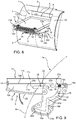
figure 2 and figure 3 show a perspective view and a side view, respectively, with parts removed for greater clarity, of the dashboard provided with table offigure 1 in a first operating condition; -
figures 4 and 5 ,6 and7 ,8 and9 ,10 and 11 show respective perspective and side views, with parts removed for greater clarity, of different moving phases of the table offigures 2 and 3 in order to move it from a first to a second operating condition; and -
figures 12 and 13 show a perspective view and a side view, respectively, with parts removed for greater clarity, of the dashboard provided with table offigure 2 in a second operating condition. -
Figure 1 shows the inside 1 of a vehicle (not shown) basically comprising adashboard 2 configured to support and/or house a plurality of known elements and provided with anouter wall 2a with any shape, in the example shown herein a concave shape towards the inside 1 of the cabin of the vehicle. Thedashboard 2 further comprises ahousing 4 configured to house, on the inside, a table 3 according to the invention. - According to
figures 6 ,8 and10 , thehousing 4 can be defined by a pair ofside walls lower wall 7, by anupper wall 8 and by abottom wall 9. Saidwalls outer wall 2a of thedashboard 2. - The depth of the
lower wall 7 inside thedashboard 2 preferably is greater than the depth of theupper wall 8 and thebottom wall 9 is inclined, preferably curved, in order to join the rear edges ofsaid walls housing 4 is open in the direction of the driver of the vehicle, at the front relative to thebottom wall 9. - The
bottom wall 9 extends inside thedashboard 2 with a depth of less than 100 mm. The table 3 comprises a firstupper half plane 11 and a secondlower half plane 12, each comprising asupport wall lower wall respective support wall side walls support walls lower walls 11bsupport walls lower walls side walls - The
half planes respective support walls half planes figures 2 to 11 ), and a second position, in which thesupport surfaces figures 12 and 13 ) defining a support plane 10 that can be used by the user of the vehicle. - This connection is advantageously obtained by means of a mechanical coupling, which is configured to allow the
half planes hinge 13 joining the twohalf planes upper half plane 11 can rotate along a transverse edge of thelower half plane 12. - According to the invention, one of the
lower walls half planes outer wall 2a of thedashboard 2 so that, when the table 3 is folded inside thehousing 4, there is continuity between thelower wall outer wall 2a of thedashboard 2. According to the embodiment described herein, thelower wall 12b of thelower half plane 12 defines a shape that is complementary to the one of theouter wall 2a of thedashboard 2, whereas thelower wall 11b has a substantially flat shape. - According to the invention, one of the two
half planes side walls housing 4 by means ofrespective cam connections side walls side walls half lanes side walls plane 12 are connected, by means ofcam connections side walls housing 4. - According to
figures 3 ,5 ,7 ,9 ,11 or13 , with reference, for the sake of simplicity, to the soleright side wall 12c, thecam mechanism 15 comprises afirst cam arrangement 17 configured to guide the movements of thehalf plane 12 so as to shift from a folded configuration to an open configuration - or vice versa - of the table 3. - According to the embodiment shown herein, the
cam arrangement 17 comprising apin 18 carried by thelower half plane 12 and configured to slide in aguide 19 obtained in theside wall 6. - According to the kinematic mechanism shown herein, the
guide 19 defines the following path, from the bottom left corner to the top right corner of theside wall 6, comprising: - a first
curved portion 19a concave in an upwards direction (namely, towards theouter wall 2a of the dashboard 2) and defining a lower end ofstroke 20a for thepin 18; - a first
straight portion 19b, vertical and extending in a continuous manner from a rear end of the firstcurved portion 19a; - a second
curved portion 19c concave in an upwards direction, with a greater bending than the firstcurved portion 19a and extending in a continuous manner from an upper end of thefirst portion 19b; and - a second
straight portion 19d, horizontal and extending in a continuous manner from a top end of the secondcurved portion 19c and further defining an upper end ofstroke 20b for thepin 18. - The intersection between the first
straight portion 19a and the firstcurved portion 19b defines a firstintermediate point 21a, which can be reached by thepin 18 during its stroke inside theguide 19, the intersection between the firstcurved portion 19b and the secondstraight portion 19c defines a secondintermediate point 21b and the intersection between the secondcurved portion 19c and the secondstraight portion 19d defines a thirdintermediate point 21c. - The
cam mechanism 15 further comprises asecond cam arrangement 23 configured to define a static constraint between thehalf plane 12 and theside walls - The
second cam arrangement 23 can comprise apin 24 carried by theside wall 6 and aguide 25 obtained on theside wall 12c of thelower half plane 12. Thehorizontal guide 25 has a length such that and is positioned in such a way that, in combination with thecam arrangement 17, it allows thelower half plane 12 to be moved. Theguide 25 defines a left end ofstroke 25a and a right end ofstrike 25b. - The
cam connection 16 between theside wall 12d of thehalf plane 12 and theside wall 6 defining thehousing 4 is mirror-like and equal to thecam connection 15 described above; therefore, it is not described for the sake of brevity. - The table 3 works as follows.
- In a first operating condition of the table 3, namely a folded condition, according to
figures 2 and 3 , thehalf planes support walls housing 4 so that thelower wall 12b of thelower half plane 12 is a continuation of theouter wall 2a of thedashboard 2. In this configuration, thepin 18 is at the lower end ofstroke 20a and thepin 24 is at the right end ofstroke 25b. - In a first moving phase of the table 3, according to
figures 4 and 5 , the driver of the vehicle can exert a force upon a lower portion of thewall 12b of thehalf plane 12, i.e. under thepin 24, so that thehalf planes pin 24 and thepin 18 moves from the lower end ofstroke 20a to the firstintermediate position 21a along the firstcurved portion 19a. - In a second moving phase of the table 3, according to
figures 6 and 7 , the driver of the vehicle applies a vertical force aimed at lifting thehalf planes housing 4. In this way, thepin 24 slides in theguide 25 from the left end ofstroke 25a to the right end ofstroke 25b and thepin 18 moves from the firstintermediate position 21a to the secondintermediate position 21b along the firststraight portion 19b. - In a third moving phase of the table 3, according to
figures 8 and 9 , the driver of the vehicle can exert a force upon a lower portion of thewall 12b of thehalf plane 12, always under thepin 24, so that thehalf planes pin 24 and thepin 18 moves from the secondintermediate position 21b to the thirdintermediate position 21c along the secondcurved portion 19c. - In a fourth moving phase of the table 3, according to
figures 10 and 11 , the driver of the vehicle applies a horizontal force aimed at pushing thehalf planes housing 4. In this way, thepin 24 slides in theguide 25 from the right end ofstroke 25b to an intermediate position between the latter and the left end of stroke and thepin 18 moves from the thirdintermediate position 21c to the upper end ofstroke 20b along the secondstraight portion 19d. - In a fifth moving phase, which is shown in
figure 13 , the driver of the vehicle can overturn thehalf plane 11 relative to thehalf plane 12, causing it to rotate around thehinge 13 so that thesupport portions figure 12 , which shows the second operating condition, namely the open condition, of the table 3. In this configuration, thanks to the position of thepins pins - The closing of the table carries out, in reverse order and in an opposite direction, the preceding phases and, hence, is not described for the sake of brevity.
- Owing to the above, the advantages of a vehicle provided with a table 3 according to the invention are evident.
- Thanks to the particular arrangement of the half planes 11, 12 and of the moving mechanism to move them relative to the
housing 4, the table 3 creates a support plane 10 having an adequate extension with a minimum space taken up, in the table extraction direction, inside thedashboard 2. - In particular, thanks to the fact that the
lower wall 12b is a continuation of theouter wall 2a of thedashboard 3, i.e. creates part thereof, the space taken up inside the dashboard is less than 100 mm, whereas the length of the support plane 10, in the opening direction of the table 3, is approximately 350 mm. - The use of a pair of
cam arrangements - Furthermore, the
cam mechanism guides housing 4, though taking up a minimum space inside thedashboard 2. - Finally, the vehicle provided with a table 3 according to the invention can be subjected to changes and variants, which, though, do not go beyond the scope of protection set forth in the appended claims.
- For example, the shape of the
outer wall 2a of thedashboard 2 and, similarly, the shape of thelower wall 12b of thehalf plane 12 can be changed according to the needs. - Or the
cam mechanisms cam arrangements - Furthermore, the
lower wall 11b of theupper half plane 11 could be, in the folded configuration, a continuation of theouter wall 2a of thedashboard 2 and thelower half plane 12 could be connected, as a consequence, to theupper half plane 11. - Moreover, the
walls single bottom wall 9 or thehinge 13 could be replaced by a different device allowing the half planes 11, 12 to be folded as described above.
Claims (9)
- A vehicle defining an inner space (1) comprising a dashboard (2) provided with an outer wall (2a) and defining a housing (4), said vehicle comprising a table (3) which can be housed in said housing (4) and comprising a first half plane (11) and a second-half plane (12) connected to each other in a foldable manner and each comprising a support wall (11a, 12a), a pair of side walls (11c, 11d, 12c, 12d) and a lower wall (11b, 12b) opposite to said support wall (11a, 12a), when said table (3) is folded inside said housing (4), said lower wall (11b, 12b) of either said first or second half plane (11, 12) being placed in continuation with said outer wall (2a) of said dashboard (2).
- The vehicle according to claim 1, wherein said housing (4) is defined inside said dashboard (2) at least a pair of side walls (5, 6) and a bottom wall (9) connected to each other, said side walls (11c, 11d, 12c, 12d) of either said first or second half planes (11, 12) being connected to said side walls (5, 6) defining said housing (4) through respective cam connections (15, 16).
- The vehicle according to claim 2, wherein said cam connections (15, 16) comprises a first cam arrangement (17) configured to guide the movements of said first and second half planes (11, 12) from said first folded position to an unfolded position of the table (3).
- The vehicle according to claim 3, wherein each of said cam connections (15, 16) comprises a second cam arrangement (23) configured to define a static constraint between one of either said first and second half planes (11, 12) and said side walls (5, 6) when said table (3) is in an open position, said static constraint preventing said one of either said first and second half planes (11, 12) from rotating in respect to said first cam arrangement (17) .
- The vehicle according to one of the claims 3 or 4, wherein said cam arrangement (17, 23) comprises a pin (18, 24), carried by one of either said first or second half planes (11, 12) and said side walls (5, 6), configured to slide along a guide (19, 25), carried by the other of said first or second half planes (11, 12) and said side walls (5, 6).
- The vehicle according to one of the claims 3 to 5, wherein said guide (19) of said first cam arrangement (17) comprises:• a first curved portion (19a) concave in an upwards direction and defining a lower end of stroke (20a) for said pin (18);• a first straight portion (19b), vertical and extending in a continuous manner from a rear end of the first curved portion (19a);• a second curved portion (19c) concave in an upwards direction and extending in a continuous manner from an upper end of said first portion (19b); and• a second straight portion (19d) horizontal and extending in a continuous manner from a top end of said second curved portion (19c) and further defining an upper end of stroke (20b) for said pin (18).
- The vehicle according to one of the claims 4 to 6, wherein said guide (25) of said second cam arrangement (23) comprises a single horizontal section defining a first and a second end of stroke (25a, 25b).
- The vehicle according to one of the preceding claims, wherein said foldable connection between said first and second half planes (11, 12) comprises a hinge (13).
- The vehicle according to one of the preceding claims, wherein said bottom wall (9) has a depth of less than 100 mm in respect to said outer wall (2a) of said dashboard (2).
Applications Claiming Priority (1)
| Application Number | Priority Date | Filing Date | Title |
|---|---|---|---|
| IT201800008807 | 2018-09-21 |
Publications (2)
| Publication Number | Publication Date |
|---|---|
| EP3626528A1 true EP3626528A1 (en) | 2020-03-25 |
| EP3626528B1 EP3626528B1 (en) | 2021-05-26 |
Family
ID=64607108
Family Applications (1)
| Application Number | Title | Priority Date | Filing Date |
|---|---|---|---|
| EP19198792.4A Active EP3626528B1 (en) | 2018-09-21 | 2019-09-20 | Vehicle provided with an improved table |
Country Status (2)
| Country | Link |
|---|---|
| EP (1) | EP3626528B1 (en) |
| ES (1) | ES2886485T3 (en) |
Cited By (1)
| Publication number | Priority date | Publication date | Assignee | Title |
|---|---|---|---|---|
| CN115230555A (en) * | 2022-08-19 | 2022-10-25 | 浙江吉利控股集团有限公司 | Instrument board and car |
Citations (5)
| Publication number | Priority date | Publication date | Assignee | Title |
|---|---|---|---|---|
| US2789861A (en) * | 1954-04-20 | 1957-04-23 | Randolph W Hudson | Glove compartment door service tray for vehicles |
| DE4327869C1 (en) * | 1993-08-19 | 1994-08-18 | Daimler Benz Ag | Parcel shelf with closing flap and folding table arranged thereon |
| EP2465377A1 (en) | 2010-12-17 | 2012-06-20 | Iveco S.p.A. | Vehicle table and corresponding housing in vehicle dashbord, in particular for industrial or commercial vehicles |
| EP2586655A1 (en) | 2011-10-25 | 2013-05-01 | IVECO S.p.A. | Foldaway table, especially for an industrial or commercial vehicle |
| EP2586656A1 (en) | 2011-10-25 | 2013-05-01 | Iveco S.p.A. | Support system of a vehicular foldaway table, in particular for industrial or commercial vehicles |
-
2019
- 2019-09-20 EP EP19198792.4A patent/EP3626528B1/en active Active
- 2019-09-20 ES ES19198792T patent/ES2886485T3/en active Active
Patent Citations (5)
| Publication number | Priority date | Publication date | Assignee | Title |
|---|---|---|---|---|
| US2789861A (en) * | 1954-04-20 | 1957-04-23 | Randolph W Hudson | Glove compartment door service tray for vehicles |
| DE4327869C1 (en) * | 1993-08-19 | 1994-08-18 | Daimler Benz Ag | Parcel shelf with closing flap and folding table arranged thereon |
| EP2465377A1 (en) | 2010-12-17 | 2012-06-20 | Iveco S.p.A. | Vehicle table and corresponding housing in vehicle dashbord, in particular for industrial or commercial vehicles |
| EP2586655A1 (en) | 2011-10-25 | 2013-05-01 | IVECO S.p.A. | Foldaway table, especially for an industrial or commercial vehicle |
| EP2586656A1 (en) | 2011-10-25 | 2013-05-01 | Iveco S.p.A. | Support system of a vehicular foldaway table, in particular for industrial or commercial vehicles |
Cited By (2)
| Publication number | Priority date | Publication date | Assignee | Title |
|---|---|---|---|---|
| CN115230555A (en) * | 2022-08-19 | 2022-10-25 | 浙江吉利控股集团有限公司 | Instrument board and car |
| CN115230555B (en) * | 2022-08-19 | 2024-02-27 | 浙江吉利控股集团有限公司 | Instrument board and car |
Also Published As
| Publication number | Publication date |
|---|---|
| ES2886485T3 (en) | 2021-12-20 |
| EP3626528B1 (en) | 2021-05-26 |
Similar Documents
| Publication | Publication Date | Title |
|---|---|---|
| CN107618445A (en) | Storage cabin separator with the dividing plate be hinged intussusception part | |
| US20150054299A1 (en) | Luggage board movement mechanism | |
| EP3500488B1 (en) | Aircraft storage bin bucket with space efficient corner joint | |
| CN104349939A (en) | Vehicle storage compartment assembly | |
| EP3626528B1 (en) | Vehicle provided with an improved table | |
| JP2017521116A (en) | Furniture support frame | |
| EP3515791B1 (en) | Reconfigurable cabin for industrial vehicle | |
| AU2015320026A1 (en) | Deformable and movable rear spoiler device for a vehicle | |
| EP2105352B1 (en) | Moveable cargo tray for the trunk of a motor vehicle | |
| CN110214112A (en) | Hinge component | |
| CN105433616B (en) | Sliding rail assembly | |
| EP2457774A1 (en) | A loading shelf for a vehicle luggage compartment | |
| CN108248474A (en) | For the extensible top of vehicle central console | |
| CN214617475U (en) | Hinge assembly | |
| EP2980318B1 (en) | Working vehicle | |
| CN101420833A (en) | Portable electronic device, and sliding/rotation opening/closing module and parts thereof for the device | |
| JP6969277B2 (en) | Rear door structure | |
| CN104097580A (en) | Adaptable bin with folding secondary bin | |
| DK2899132T3 (en) | Container with lockable cargo opening | |
| JP4261499B2 (en) | Vehicle table structure | |
| EP3205240B1 (en) | Basic structure for a display stand, display stand and method of erecting said display stand | |
| JP5375718B2 (en) | Moving body receiving device | |
| CN111356612B (en) | Internal assembly for supporting a load arranged in an upper internal part of a vehicle | |
| JP2007230268A (en) | Vehicle skeleton member | |
| JP6544011B2 (en) | Sunroof device |
Legal Events
| Date | Code | Title | Description |
|---|---|---|---|
| PUAI | Public reference made under article 153(3) epc to a published international application that has entered the european phase |
Free format text: ORIGINAL CODE: 0009012 |
|
| STAA | Information on the status of an ep patent application or granted ep patent |
Free format text: STATUS: THE APPLICATION HAS BEEN PUBLISHED |
|
| AK | Designated contracting states |
Kind code of ref document: A1 Designated state(s): AL AT BE BG CH CY CZ DE DK EE ES FI FR GB GR HR HU IE IS IT LI LT LU LV MC MK MT NL NO PL PT RO RS SE SI SK SM TR |
|
| AX | Request for extension of the european patent |
Extension state: BA ME |
|
| STAA | Information on the status of an ep patent application or granted ep patent |
Free format text: STATUS: REQUEST FOR EXAMINATION WAS MADE |
|
| 17P | Request for examination filed |
Effective date: 20200916 |
|
| RBV | Designated contracting states (corrected) |
Designated state(s): AL AT BE BG CH CY CZ DE DK EE ES FI FR GB GR HR HU IE IS IT LI LT LU LV MC MK MT NL NO PL PT RO RS SE SI SK SM TR |
|
| GRAP | Despatch of communication of intention to grant a patent |
Free format text: ORIGINAL CODE: EPIDOSNIGR1 |
|
| STAA | Information on the status of an ep patent application or granted ep patent |
Free format text: STATUS: GRANT OF PATENT IS INTENDED |
|
| INTG | Intention to grant announced |
Effective date: 20201223 |
|
| GRAS | Grant fee paid |
Free format text: ORIGINAL CODE: EPIDOSNIGR3 |
|
| GRAA | (expected) grant |
Free format text: ORIGINAL CODE: 0009210 |
|
| STAA | Information on the status of an ep patent application or granted ep patent |
Free format text: STATUS: THE PATENT HAS BEEN GRANTED |
|
| AK | Designated contracting states |
Kind code of ref document: B1 Designated state(s): AL AT BE BG CH CY CZ DE DK EE ES FI FR GB GR HR HU IE IS IT LI LT LU LV MC MK MT NL NO PL PT RO RS SE SI SK SM TR |
|
| REG | Reference to a national code |
Ref country code: GB Ref legal event code: FG4D |
|
| REG | Reference to a national code |
Ref country code: CH Ref legal event code: EP |
|
| REG | Reference to a national code |
Ref country code: DE Ref legal event code: R096 Ref document number: 602019004885 Country of ref document: DE |
|
| REG | Reference to a national code |
Ref country code: AT Ref legal event code: REF Ref document number: 1395906 Country of ref document: AT Kind code of ref document: T Effective date: 20210615 |
|
| REG | Reference to a national code |
Ref country code: IE Ref legal event code: FG4D |
|
| REG | Reference to a national code |
Ref country code: LT Ref legal event code: MG9D |
|
| REG | Reference to a national code |
Ref country code: AT Ref legal event code: MK05 Ref document number: 1395906 Country of ref document: AT Kind code of ref document: T Effective date: 20210526 |
|
| PG25 | Lapsed in a contracting state [announced via postgrant information from national office to epo] |
Ref country code: AT Free format text: LAPSE BECAUSE OF FAILURE TO SUBMIT A TRANSLATION OF THE DESCRIPTION OR TO PAY THE FEE WITHIN THE PRESCRIBED TIME-LIMIT Effective date: 20210526 Ref country code: BG Free format text: LAPSE BECAUSE OF FAILURE TO SUBMIT A TRANSLATION OF THE DESCRIPTION OR TO PAY THE FEE WITHIN THE PRESCRIBED TIME-LIMIT Effective date: 20210826 Ref country code: FI Free format text: LAPSE BECAUSE OF FAILURE TO SUBMIT A TRANSLATION OF THE DESCRIPTION OR TO PAY THE FEE WITHIN THE PRESCRIBED TIME-LIMIT Effective date: 20210526 Ref country code: LT Free format text: LAPSE BECAUSE OF FAILURE TO SUBMIT A TRANSLATION OF THE DESCRIPTION OR TO PAY THE FEE WITHIN THE PRESCRIBED TIME-LIMIT Effective date: 20210526 Ref country code: HR Free format text: LAPSE BECAUSE OF FAILURE TO SUBMIT A TRANSLATION OF THE DESCRIPTION OR TO PAY THE FEE WITHIN THE PRESCRIBED TIME-LIMIT Effective date: 20210526 |
|
| REG | Reference to a national code |
Ref country code: NL Ref legal event code: MP Effective date: 20210526 |
|
| PG25 | Lapsed in a contracting state [announced via postgrant information from national office to epo] |
Ref country code: GR Free format text: LAPSE BECAUSE OF FAILURE TO SUBMIT A TRANSLATION OF THE DESCRIPTION OR TO PAY THE FEE WITHIN THE PRESCRIBED TIME-LIMIT Effective date: 20210827 Ref country code: IS Free format text: LAPSE BECAUSE OF FAILURE TO SUBMIT A TRANSLATION OF THE DESCRIPTION OR TO PAY THE FEE WITHIN THE PRESCRIBED TIME-LIMIT Effective date: 20210926 Ref country code: LV Free format text: LAPSE BECAUSE OF FAILURE TO SUBMIT A TRANSLATION OF THE DESCRIPTION OR TO PAY THE FEE WITHIN THE PRESCRIBED TIME-LIMIT Effective date: 20210526 Ref country code: NO Free format text: LAPSE BECAUSE OF FAILURE TO SUBMIT A TRANSLATION OF THE DESCRIPTION OR TO PAY THE FEE WITHIN THE PRESCRIBED TIME-LIMIT Effective date: 20210826 Ref country code: PL Free format text: LAPSE BECAUSE OF FAILURE TO SUBMIT A TRANSLATION OF THE DESCRIPTION OR TO PAY THE FEE WITHIN THE PRESCRIBED TIME-LIMIT Effective date: 20210526 Ref country code: RS Free format text: LAPSE BECAUSE OF FAILURE TO SUBMIT A TRANSLATION OF THE DESCRIPTION OR TO PAY THE FEE WITHIN THE PRESCRIBED TIME-LIMIT Effective date: 20210526 Ref country code: SE Free format text: LAPSE BECAUSE OF FAILURE TO SUBMIT A TRANSLATION OF THE DESCRIPTION OR TO PAY THE FEE WITHIN THE PRESCRIBED TIME-LIMIT Effective date: 20210526 Ref country code: PT Free format text: LAPSE BECAUSE OF FAILURE TO SUBMIT A TRANSLATION OF THE DESCRIPTION OR TO PAY THE FEE WITHIN THE PRESCRIBED TIME-LIMIT Effective date: 20210927 |
|
| REG | Reference to a national code |
Ref country code: ES Ref legal event code: FG2A Ref document number: 2886485 Country of ref document: ES Kind code of ref document: T3 Effective date: 20211220 |
|
| PG25 | Lapsed in a contracting state [announced via postgrant information from national office to epo] |
Ref country code: NL Free format text: LAPSE BECAUSE OF FAILURE TO SUBMIT A TRANSLATION OF THE DESCRIPTION OR TO PAY THE FEE WITHIN THE PRESCRIBED TIME-LIMIT Effective date: 20210526 |
|
| PG25 | Lapsed in a contracting state [announced via postgrant information from national office to epo] |
Ref country code: SK Free format text: LAPSE BECAUSE OF FAILURE TO SUBMIT A TRANSLATION OF THE DESCRIPTION OR TO PAY THE FEE WITHIN THE PRESCRIBED TIME-LIMIT Effective date: 20210526 Ref country code: EE Free format text: LAPSE BECAUSE OF FAILURE TO SUBMIT A TRANSLATION OF THE DESCRIPTION OR TO PAY THE FEE WITHIN THE PRESCRIBED TIME-LIMIT Effective date: 20210526 Ref country code: SM Free format text: LAPSE BECAUSE OF FAILURE TO SUBMIT A TRANSLATION OF THE DESCRIPTION OR TO PAY THE FEE WITHIN THE PRESCRIBED TIME-LIMIT Effective date: 20210526 Ref country code: RO Free format text: LAPSE BECAUSE OF FAILURE TO SUBMIT A TRANSLATION OF THE DESCRIPTION OR TO PAY THE FEE WITHIN THE PRESCRIBED TIME-LIMIT Effective date: 20210526 Ref country code: DK Free format text: LAPSE BECAUSE OF FAILURE TO SUBMIT A TRANSLATION OF THE DESCRIPTION OR TO PAY THE FEE WITHIN THE PRESCRIBED TIME-LIMIT Effective date: 20210526 Ref country code: CZ Free format text: LAPSE BECAUSE OF FAILURE TO SUBMIT A TRANSLATION OF THE DESCRIPTION OR TO PAY THE FEE WITHIN THE PRESCRIBED TIME-LIMIT Effective date: 20210526 |
|
| REG | Reference to a national code |
Ref country code: DE Ref legal event code: R097 Ref document number: 602019004885 Country of ref document: DE |
|
| PLBE | No opposition filed within time limit |
Free format text: ORIGINAL CODE: 0009261 |
|
| STAA | Information on the status of an ep patent application or granted ep patent |
Free format text: STATUS: NO OPPOSITION FILED WITHIN TIME LIMIT |
|
| 26N | No opposition filed |
Effective date: 20220301 |
|
| REG | Reference to a national code |
Ref country code: BE Ref legal event code: MM Effective date: 20210930 |
|
| PG25 | Lapsed in a contracting state [announced via postgrant information from national office to epo] |
Ref country code: IS Free format text: LAPSE BECAUSE OF FAILURE TO SUBMIT A TRANSLATION OF THE DESCRIPTION OR TO PAY THE FEE WITHIN THE PRESCRIBED TIME-LIMIT Effective date: 20210926 Ref country code: MC Free format text: LAPSE BECAUSE OF FAILURE TO SUBMIT A TRANSLATION OF THE DESCRIPTION OR TO PAY THE FEE WITHIN THE PRESCRIBED TIME-LIMIT Effective date: 20210526 Ref country code: AL Free format text: LAPSE BECAUSE OF FAILURE TO SUBMIT A TRANSLATION OF THE DESCRIPTION OR TO PAY THE FEE WITHIN THE PRESCRIBED TIME-LIMIT Effective date: 20210526 |
|
| PG25 | Lapsed in a contracting state [announced via postgrant information from national office to epo] |
Ref country code: LU Free format text: LAPSE BECAUSE OF NON-PAYMENT OF DUE FEES Effective date: 20210920 Ref country code: IE Free format text: LAPSE BECAUSE OF NON-PAYMENT OF DUE FEES Effective date: 20210920 Ref country code: BE Free format text: LAPSE BECAUSE OF NON-PAYMENT OF DUE FEES Effective date: 20210930 |
|
| REG | Reference to a national code |
Ref country code: CH Ref legal event code: PL |
|
| P01 | Opt-out of the competence of the unified patent court (upc) registered |
Effective date: 20230523 |
|
| PG25 | Lapsed in a contracting state [announced via postgrant information from national office to epo] |
Ref country code: CY Free format text: LAPSE BECAUSE OF FAILURE TO SUBMIT A TRANSLATION OF THE DESCRIPTION OR TO PAY THE FEE WITHIN THE PRESCRIBED TIME-LIMIT Effective date: 20210526 |
|
| PG25 | Lapsed in a contracting state [announced via postgrant information from national office to epo] |
Ref country code: LI Free format text: LAPSE BECAUSE OF NON-PAYMENT OF DUE FEES Effective date: 20220930 Ref country code: HU Free format text: LAPSE BECAUSE OF FAILURE TO SUBMIT A TRANSLATION OF THE DESCRIPTION OR TO PAY THE FEE WITHIN THE PRESCRIBED TIME-LIMIT; INVALID AB INITIO Effective date: 20190920 Ref country code: CH Free format text: LAPSE BECAUSE OF NON-PAYMENT OF DUE FEES Effective date: 20220930 |
|
| PGFP | Annual fee paid to national office [announced via postgrant information from national office to epo] |
Ref country code: IT Payment date: 20230913 Year of fee payment: 5 |
|
| PGFP | Annual fee paid to national office [announced via postgrant information from national office to epo] |
Ref country code: ES Payment date: 20231017 Year of fee payment: 5 |
|
| PG25 | Lapsed in a contracting state [announced via postgrant information from national office to epo] |
Ref country code: MK Free format text: LAPSE BECAUSE OF FAILURE TO SUBMIT A TRANSLATION OF THE DESCRIPTION OR TO PAY THE FEE WITHIN THE PRESCRIBED TIME-LIMIT Effective date: 20210526 |
|
| PG25 | Lapsed in a contracting state [announced via postgrant information from national office to epo] |
Ref country code: MT Free format text: LAPSE BECAUSE OF FAILURE TO SUBMIT A TRANSLATION OF THE DESCRIPTION OR TO PAY THE FEE WITHIN THE PRESCRIBED TIME-LIMIT Effective date: 20210526 |
|
| PGFP | Annual fee paid to national office [announced via postgrant information from national office to epo] |
Ref country code: DE Payment date: 20240926 Year of fee payment: 6 |
|
| PGFP | Annual fee paid to national office [announced via postgrant information from national office to epo] |
Ref country code: GB Payment date: 20240924 Year of fee payment: 6 |
|
| PGFP | Annual fee paid to national office [announced via postgrant information from national office to epo] |
Ref country code: FR Payment date: 20240925 Year of fee payment: 6 |