EP3626495B1 - Window assembly for use in a vehicle - Google Patents
Window assembly for use in a vehicle Download PDFInfo
- Publication number
- EP3626495B1 EP3626495B1 EP19198362.6A EP19198362A EP3626495B1 EP 3626495 B1 EP3626495 B1 EP 3626495B1 EP 19198362 A EP19198362 A EP 19198362A EP 3626495 B1 EP3626495 B1 EP 3626495B1
- Authority
- EP
- European Patent Office
- Prior art keywords
- shade
- opaque
- transparent
- tab
- window
- Prior art date
- Legal status (The legal status is an assumption and is not a legal conclusion. Google has not performed a legal analysis and makes no representation as to the accuracy of the status listed.)
- Active
Links
- 230000010354 integration Effects 0.000 claims description 8
- 230000001419 dependent effect Effects 0.000 description 8
- 230000009977 dual effect Effects 0.000 description 3
- 230000000712 assembly Effects 0.000 description 2
- 238000000429 assembly Methods 0.000 description 2
- 238000000034 method Methods 0.000 description 2
- 238000002834 transmittance Methods 0.000 description 2
- 238000001914 filtration Methods 0.000 description 1
- 230000003760 hair shine Effects 0.000 description 1
- 238000000465 moulding Methods 0.000 description 1
Images


Classifications
-
- E—FIXED CONSTRUCTIONS
- E06—DOORS, WINDOWS, SHUTTERS, OR ROLLER BLINDS IN GENERAL; LADDERS
- E06B—FIXED OR MOVABLE CLOSURES FOR OPENINGS IN BUILDINGS, VEHICLES, FENCES OR LIKE ENCLOSURES IN GENERAL, e.g. DOORS, WINDOWS, BLINDS, GATES
- E06B3/00—Window sashes, door leaves, or like elements for closing wall or like openings; Layout of fixed or moving closures, e.g. windows in wall or like openings; Features of rigidly-mounted outer frames relating to the mounting of wing frames
- E06B3/32—Arrangements of wings characterised by the manner of movement; Arrangements of movable wings in openings; Features of wings or frames relating solely to the manner of movement of the wing
- E06B3/34—Arrangements of wings characterised by the manner of movement; Arrangements of movable wings in openings; Features of wings or frames relating solely to the manner of movement of the wing with only one kind of movement
- E06B3/42—Sliding wings; Details of frames with respect to guiding
- E06B3/44—Vertically-sliding wings
- E06B3/4423—Vertically-sliding wings disappearing in a wall pocket; Pockets therefor
-
- B—PERFORMING OPERATIONS; TRANSPORTING
- B64—AIRCRAFT; AVIATION; COSMONAUTICS
- B64C—AEROPLANES; HELICOPTERS
- B64C1/00—Fuselages; Constructional features common to fuselages, wings, stabilising surfaces or the like
- B64C1/14—Windows; Doors; Hatch covers or access panels; Surrounding frame structures; Canopies; Windscreens accessories therefor, e.g. pressure sensors, water deflectors, hinges, seals, handles, latches, windscreen wipers
- B64C1/1476—Canopies; Windscreens or similar transparent elements
- B64C1/1484—Windows
-
- E—FIXED CONSTRUCTIONS
- E06—DOORS, WINDOWS, SHUTTERS, OR ROLLER BLINDS IN GENERAL; LADDERS
- E06B—FIXED OR MOVABLE CLOSURES FOR OPENINGS IN BUILDINGS, VEHICLES, FENCES OR LIKE ENCLOSURES IN GENERAL, e.g. DOORS, WINDOWS, BLINDS, GATES
- E06B9/00—Screening or protective devices for wall or similar openings, with or without operating or securing mechanisms; Closures of similar construction
- E06B9/24—Screens or other constructions affording protection against light, especially against sunshine; Similar screens for privacy or appearance; Slat blinds
-
- B—PERFORMING OPERATIONS; TRANSPORTING
- B60—VEHICLES IN GENERAL
- B60J—WINDOWS, WINDSCREENS, NON-FIXED ROOFS, DOORS, OR SIMILAR DEVICES FOR VEHICLES; REMOVABLE EXTERNAL PROTECTIVE COVERINGS SPECIALLY ADAPTED FOR VEHICLES
- B60J1/00—Windows; Windscreens; Accessories therefor
- B60J1/20—Accessories, e.g. wind deflectors, blinds
- B60J1/2011—Blinds; curtains or screens reducing heat or light intensity
-
- B—PERFORMING OPERATIONS; TRANSPORTING
- B64—AIRCRAFT; AVIATION; COSMONAUTICS
- B64C—AEROPLANES; HELICOPTERS
- B64C1/00—Fuselages; Constructional features common to fuselages, wings, stabilising surfaces or the like
- B64C1/14—Windows; Doors; Hatch covers or access panels; Surrounding frame structures; Canopies; Windscreens accessories therefor, e.g. pressure sensors, water deflectors, hinges, seals, handles, latches, windscreen wipers
- B64C1/1476—Canopies; Windscreens or similar transparent elements
- B64C1/1492—Structure and mounting of the transparent elements in the window or windscreen
-
- E—FIXED CONSTRUCTIONS
- E06—DOORS, WINDOWS, SHUTTERS, OR ROLLER BLINDS IN GENERAL; LADDERS
- E06B—FIXED OR MOVABLE CLOSURES FOR OPENINGS IN BUILDINGS, VEHICLES, FENCES OR LIKE ENCLOSURES IN GENERAL, e.g. DOORS, WINDOWS, BLINDS, GATES
- E06B3/00—Window sashes, door leaves, or like elements for closing wall or like openings; Layout of fixed or moving closures, e.g. windows in wall or like openings; Features of rigidly-mounted outer frames relating to the mounting of wing frames
- E06B3/32—Arrangements of wings characterised by the manner of movement; Arrangements of movable wings in openings; Features of wings or frames relating solely to the manner of movement of the wing
- E06B3/34—Arrangements of wings characterised by the manner of movement; Arrangements of movable wings in openings; Features of wings or frames relating solely to the manner of movement of the wing with only one kind of movement
- E06B3/42—Sliding wings; Details of frames with respect to guiding
- E06B3/44—Vertically-sliding wings
- E06B2003/4438—Vertically-sliding wings characterised by the material used for the frames
- E06B2003/4461—Plastics
-
- E—FIXED CONSTRUCTIONS
- E06—DOORS, WINDOWS, SHUTTERS, OR ROLLER BLINDS IN GENERAL; LADDERS
- E06B—FIXED OR MOVABLE CLOSURES FOR OPENINGS IN BUILDINGS, VEHICLES, FENCES OR LIKE ENCLOSURES IN GENERAL, e.g. DOORS, WINDOWS, BLINDS, GATES
- E06B3/00—Window sashes, door leaves, or like elements for closing wall or like openings; Layout of fixed or moving closures, e.g. windows in wall or like openings; Features of rigidly-mounted outer frames relating to the mounting of wing frames
- E06B3/32—Arrangements of wings characterised by the manner of movement; Arrangements of movable wings in openings; Features of wings or frames relating solely to the manner of movement of the wing
- E06B3/34—Arrangements of wings characterised by the manner of movement; Arrangements of movable wings in openings; Features of wings or frames relating solely to the manner of movement of the wing with only one kind of movement
- E06B3/42—Sliding wings; Details of frames with respect to guiding
- E06B3/44—Vertically-sliding wings
- E06B2003/4492—Vertically-sliding wings provided with screens
Definitions
- the field of the present disclosure relates generally to window shades in a vehicle and, more specifically, to a dual retractable window shade assembly.
- a passenger has the ability to manually alter the amount of light that shines through a window in the vehicle.
- the windows on at least some known passenger aircraft include a plastic shade that is slidable relative to the window for selectively covering a window opening.
- the plastic shade is typically opaque such that the passage of light through the window opening and into a passenger compartment of the aircraft is blocked when the shade is fully drawn.
- retracting the shade from the fully drawn position may result in the passenger compartment being suddenly flooded with light, which may be undesirable from a passenger perspective.
- At least some known vehicles have dual retractable window shades, where one window shade is a darker opaque shade than the other window shade.
- the darker shade generally blocks the passage of light therethrough, and the lighter shade allows some light to pass therethrough such that the passenger has the ability to select a desired level of brightness.
- the window shades are independently movable relative to each other, which enables the passenger compartment to be flooded with light if the lighter shade is retracted before the darker shade.
- US7510146B2 describes, in accordance with its abstract, a window shade system.
- This system has a series of individual window shade units, each having a multilayer shade configuration.
- Such multilayer shade configuration provides for a degree of control with regard to the amount of incidental light actually allowed to enter a passenger compartment.
- each individual window shade unit is fully automated and may be linked to an adjacent window shade unit in a daisy chain fashion.
- This system presents features in the window shade itself, within the electronic components that operate the window shade, and the relationship between the system and its operators.
- the present disclosure provides a window assembly for use in a vehicle, as defined in claim 1.
- a window assembly for use in a vehicle, as defined in claim 1.
- Optional features of aspects of the invention are set out in the dependent claims.
- the implementations described herein relate to a dual retractable window shade assembly. More specifically, the assembly described herein includes an opaque shade and a transparent shade that is tinted.
- the opaque shade and the transparent shade each include a tab formed at the bottom ends thereof.
- the tabs provide a structure for a passenger to grip such that the passenger can manually open and close the shades.
- the tabs are also designed for selectively integration with each other to enable dependent movement of the shades with each other, but also to enable independent movement of the shades relative to each other. For example, the tabs are separated from each other when the shades are in a fully retracted position, which enables the passenger to select which shade to draw over a window opening.
- the tab on the opaque shade engages the tab on the transparent shade such that both shades are drawn together.
- the transparent shade is already drawn when the passenger decides to retract the opaque shade, which facilitates automatically filtering the amount of light allowed to shine the window opening.
- the tabs are nested together in a manner that provides access to the tab on the opaque shade, but restricts access to the tab on the transparent shade.
- the passenger is restricted from retracting the transparent shade before the opaque shade, thereby limiting unintentional flooding of light through the window opening.
- the window shade assembly described herein provides an enhanced travel experience for passengers of a vehicle in a user-friendly manner.
- FIG. 1 is a side view illustration of a vehicle such as an aircraft 100.
- aircraft 100 includes a fuselage 102 defining a passenger compartment 104, and a wing 106 coupled to and extending from fuselage 102.
- Fuselage 102 also includes a plurality of window assemblies 108 extending along fuselage 102. Window assemblies 108 are selectively operable to provide passengers seated within passenger compartment 104 with a view exterior of aircraft 100.
- FIGS. 2-7 are illustrations of a window assembly 108 in various stages of operation.
- window assembly 108 includes a window frame 110, an opaque shade 112, and a transparent shade 114.
- Opaque shade 112 and transparent shade 114 are movable relative to window frame 110.
- Opaque shade 112 and transparent shade 114 are rigid parts that maintain their original shape when moved relative to window frame 110.
- Opaque shade 112 is positioned inward from transparent shade 114 relative to passenger compartment 104 (i.e., an interior) of aircraft 100 (both shown in FIG. 1 ).
- Opaque shade 112 has a visible light transmittance value of about 0 percent.
- Transparent shade 114 is tinted and has a visible light transmittance value greater than about 1 percent, greater than about 10 percent, or greater than about 25 percent.
- Window frame 110 has a first end 116 and a second end 118 opposite first end 116.
- Opaque shade 112 and transparent shade 114 are movable relative to window frame 110.
- opaque shade 112 and transparent shade 114 are both selectively retractable within, and selectively extendable from, first end 116 of window frame 110.
- opaque shade 112 includes a first tab 120 formed at a bottom end 122 thereof
- transparent shade 114 includes a second tab 124 formed at a bottom end 126 thereof.
- first tab 120 and second tab 124 provide passengers seated within passenger compartment 104 with the ability to manually locate opaque shade 112 and transparent shade 114 in a desired position.
- opaque shade 112 and transparent shade 114 are selectively integrated to enable dependent movement of opaque shade 112 and transparent shade 114 with each other, and to enable independent movement of opaque shade 112 and transparent shade 114 relative to each other.
- first tab 120 and second tab 124 are configured for selective integration to enable the dependent and independent movement of opaque shade 112 and transparent shade 114. The selective integration facilitates dependent retraction of opaque shade 112 with transparent shade 114, and facilitates dependent extension of transparent shade 114 with opaque shade 112.
- opaque shade 112 is dependently retractable with transparent shade 114 such that transparent shade 114 is not retractable past opaque shade when transparent shade 114 is moved towards first end 116, and transparent shade 114 is dependently extendable with opaque shade 112 such that opaque shade 112 is not extendable past transparent shade 114 when opaque shade 112 is moved from first end 116.
- the selective integration also facilitates independent retraction of opaque shade 112 relative to transparent shade 114, and facilitates independent extension of transparent shade 114 relative to opaque shade 112.
- opaque shade 112 and transparent shade 114 are both fully retracted within first end 116 of window frame 110.
- First tab 120 and second tab 124 are separated from each other when opaque shade 112 and transparent shade 114 are both in a fully retracted position.
- either opaque shade 112 or transparent shade 114 may be drawn based on a level of light passage into passenger compartment 104 (shown in FIG. 1 ) that is desired by a passenger.
- opaque shade 112 is extended from first end 116 of window frame 110 to an intermediate position between first end 116 and second end 118 (i.e., opaque shade 112 is partially drawn). Extending opaque shade 112 from first end 116 of window frame 110 facilitates integrating first tab 120 with second tab 124 (not shown in FIG. 3 ). When first tab 120 is integrated with second tab 124, transparent shade 114 is dependently extendable from first end 116 along with opaque shade 112. As such, as illustrated in FIG. 3 , transparent shade 114 is extended from first end 116 of window frame 110 to the intermediate position along with opaque shade 112. Thus, transparent shade 114 is automatically drawn and is positioned to reduce the passage of light into passenger compartment 104 if opaque shade 112 is retracted relative to transparent shade 114 from the intermediate position.
- first tab 120 and second tab 124 When first tab 120 and second tab 124 are integrated with each other, access to transparent shade 114 and to second tab 124 is at least partially restricted.
- first tab 120 and second tab 124 are nested with each other when opaque shade 112 and transparent shade 114 are coextensive and positioned at the same location between first end 116 and second end 118.
- first tab 120 and second tab 124 are nested with each other, only first tab 120 is accessible to a passenger seated within passenger compartment 104 (shown in FIG. 1 ). As such, the passenger only has the ability to grip first tab 120, and opaque shade 112 and transparent shade 114 are drawn automatically and simultaneously when opaque shade 112 is extended from first end 116.
- transparent shade 114 is at least partially obscured from view from within passenger compartment 104 when opaque shade 112 and transparent shade 114 are coextensive and positioned at the same location between first end 116 and second end 118. That is, transparent shade 114 is hidden behind opaque shade 112 and only a portion of bottom end 126 of transparent shade 114 is exposed when opaque shade 112 and transparent shade 114 are coextensive. As such, only opaque shade 112 is readily apparent to the passenger such that the passenger is encouraged to retract opaque shade 112 independently of transparent shade 114. However, the passenger also has the ability to grip bottom end 126 to facilitate independent extension of transparent shade 114 relative to opaque shade 112.
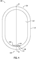
- opaque shade 112 and transparent shade 114 are both fully extended and in a closed position (i.e., opaque shade 112 and transparent shade 114 are both fully drawn). Although transparent shade 114 is not visible in FIG. 4 , opaque shade 112 and transparent shade 114 are selectively integrated to enable dependent movement of transparent shade 114 with opaque shade 112 when extended from first end 116.
- First tab 120 and second tab 124 are nested with each other when opaque shade 112 and transparent shade 114 are both in a fully extended position.
- first tab 120 and second tab 124 are nested with each other and when opaque shade 112 and transparent shade 114 are both in a fully extended position, access to transparent shade 114 and to second tab 124 is at least partially restricted.
- first tab 120 is visible to a passenger seated within passenger compartment 104 (shown in FIG. 1 ) when first tab 120 and second tab 124 are nested with each other.
- a gap 128 is defined between bottom end 122 of opaque shade 112 and second end 118 of window frame 110 when opaque shade 112 is in a fully extended position.
- Gap 128 is sized to restrict access to transparent shade 114 from passenger compartment 104. As such, the passenger is compelled to retract opaque shade 112 independently of transparent shade 114 when a decision is made to open window assembly 108.
- opaque shade 112 is partially retracted ( FIG. 5 ) or fully retracted ( FIG. 6 ), and transparent shade 114 is fully extended and in a closed position.
- Opaque shade 112 is independently movable relative to transparent shade 114.
- opaque shade 112 is retractable within first end 116 of window frame 110 while transparent shade 114 remains in the fully extended and closed position.
- Transparent shade 114 is held in a stationary position relative to opaque shade 112 to restrict inadvertent retraction of transparent shade 114 with opaque shade 112, as will be explained in more detail below.
- a passenger must make a conscious decision to retract transparent shade 114 and to potentially flood passenger compartment 104 (shown in FIG. 1 ) with light.
- opaque shade 112 is fully retracted and transparent shade 114 is retracted to an intermediate position between first end 116 and second end 118 (i.e., transparent shade 114 is partially drawn). Retracting opaque shade 112 relative to transparent shade 114 facilitates exposing, and facilitates providing a passenger access to, second tab 124. As such, the passenger has the ability to position transparent shade 114 at any desired location between first end 116 and second end 118.
- FIGS. 8-11 are cross-sectional views of window assembly 108.
- aircraft 100 includes an exterior skin 130 and an interior wall 132 spaced a distance from exterior skin 130.
- Exterior skin 130 includes a first window pane 134 coupled thereto, and window frame 110 is coupled to interior wall 132.
- Window frame 110 includes a window opening 136 and a second window pane 138 that extends across window opening 136.
- window assembly 108 includes a first frictional slide track 140 and a second frictional slide track 142 that are both positioned between exterior skin 130 and interior wall 132.
- Opaque shade 112 is movable within first frictional slide track 140
- transparent shade 114 is movable within second frictional slide track 142.
- First frictional slide track 140 and second frictional slide track 142 are vertically offset from window opening 136. As such, first frictional slide track 140 and second frictional slide track 142 are positioned such that opaque shade 112 and transparent shade 114 are both selectively retractable within, and selectively extendable from, first end 116 of window frame 110.
- first tab 120 and second tab 124 are separated from each other when opaque shade 112 and transparent shade 114 are both in a fully retracted position.
- a gap 144 is defined between first tab 120 and second tab 124 when opaque shade 112 and transparent shade 114 are both in the fully retracted position.
- first tab 120 and second tab 124 are both accessible to a passenger, and either shade may be drawn.
- First tab 120 and second tab 124 are configured for selective integration with each other.
- first tab 120 includes a first portion 146 and a second portion 148.
- First portion 146 extends from a first side 150 of opaque shade 112 towards an interior (i.e., the passenger compartment 104) of aircraft 100, and second portion 148 extends from a second side 152 of opaque shade 112 towards transparent shade 114.
- First portion 146 is formed at a bottom edge 154 of opaque shade 112, and second portion 148 is spaced a distance from bottom edge 154.
- second portion 148 defines a recess 156 in opaque shade 112 sized to receive second tab 124 therein.
- recess 156 has a depth substantially equal to a thickness of second tab 124, and a width of second tab 124 is less than a width of first tab 120.
- second tab 124 is nested within recess 156 to define the integration between first tab 120 and second tab 124.
- second portion 148 is positioned closer to first end 116 than second tab 124 to enable the dependent movement of transparent shade 114 with opaque shade 112 and to enable the independent movement of opaque shade 112 relative to transparent shade 114.
- opaque shade 112 and transparent shade 114 are in a fully extended and closed position.
- second tab 124 is spaced a distance from a bottom edge 158 of transparent shade 114, and window frame 110 includes a receiving slot 160 defined therein at second end 118.
- Receiving slot 160 is configured to receive bottom end 126 of transparent shade 114 such that transparent shade 114 is secured to window frame 110 when in the fully extended position.
- window frame 110 does not include a receiving slot for receiving bottom end 122 of opaque shade 112, and opaque shade 112 is secured in the fully extended position by virtue of the integration between first tab 120 and second tab 124.
- the distance defined between second tab 124 and bottom edge 158 is greater than a depth of receiving slot 160.
- gap 128 is defined between window frame 110 and second tab 124 when transparent shade 114 is in the fully extended position. Gap 128 is sized to enable a passenger's fingers to be inserted therein to facilitate removal of bottom end 126 from receiving slot 160 and lifting of transparent shade 114.
- first tab 120 and second tab 124 are designed to restrict inadvertent retraction of transparent shade 114 with opaque shade 112 when opaque shade 112 and transparent shade 114 are in the fully extended position.
- window frame 110 includes an interior edge 162 that defines a plane 164 of window opening 136.
- First tab 120 has a length such that first tab 120 extends beyond plane 164 defined by window frame 110.
- first tab 120 extends into passenger compartment 104 and is positioned for accessibility by a passenger seated therein.
- second tab 124 is oriented to extend towards an interior of the vehicle (i.e., passenger compartment 104 of aircraft 100), and second tab 124 has a length such that second tab 124 does not extend beyond plane 164 defined by window frame 110.
- second tab 124 is retracted relative to passenger compartment 104, which increases the difficulty to inadvertently access second tab 124 when attempting to lift opaque shade 112.
- FIG. 12 is a perspective view of an example frictional slide track assembly 166.
- frictional slide track assembly 166 includes first frictional slide track 140 and second frictional slide track 142.
- First frictional slide track 140 and second frictional slide track 142 may be either formed separately from each other and then coupled together, or may be formed as an integral, unitary, and monolithic structure, such as in a single molding process.
- first frictional slide track 140 is configured to hold opaque shade 112 at any location relative to window frame 110 (not shown in FIG. 12 )
- second frictional slide track 142 is configured to hold transparent shade 114 at any location relative to window frame 110.
- Opaque shade 112 and transparent shade 114 are positioned within their respective slide tracks with an interference fit. As such, the interference fit facilitates holding opaque shade 112 and transparent shade 114 in a particular location.
Landscapes
- Engineering & Computer Science (AREA)
- Structural Engineering (AREA)
- Mechanical Engineering (AREA)
- Aviation & Aerospace Engineering (AREA)
- Civil Engineering (AREA)
- Architecture (AREA)
- Window Of Vehicle (AREA)
- Operating, Guiding And Securing Of Roll- Type Closing Members (AREA)
Description
- The field of the present disclosure relates generally to window shades in a vehicle and, more specifically, to a dual retractable window shade assembly.
- In at least some known vehicles, such as passenger aircraft, a passenger has the ability to manually alter the amount of light that shines through a window in the vehicle. For example, the windows on at least some known passenger aircraft include a plastic shade that is slidable relative to the window for selectively covering a window opening. The plastic shade is typically opaque such that the passage of light through the window opening and into a passenger compartment of the aircraft is blocked when the shade is fully drawn. However, retracting the shade from the fully drawn position may result in the passenger compartment being suddenly flooded with light, which may be undesirable from a passenger perspective. At least some known vehicles have dual retractable window shades, where one window shade is a darker opaque shade than the other window shade. The darker shade generally blocks the passage of light therethrough, and the lighter shade allows some light to pass therethrough such that the passenger has the ability to select a desired level of brightness. However, the window shades are independently movable relative to each other, which enables the passenger compartment to be flooded with light if the lighter shade is retracted before the darker shade.
-
US7510146B2 describes, in accordance with its abstract, a window shade system. This system has a series of individual window shade units, each having a multilayer shade configuration. Such multilayer shade configuration provides for a degree of control with regard to the amount of incidental light actually allowed to enter a passenger compartment. Further, each individual window shade unit is fully automated and may be linked to an adjacent window shade unit in a daisy chain fashion. This system presents features in the window shade itself, within the electronic components that operate the window shade, and the relationship between the system and its operators. - According to the invention, the present disclosure provides a window assembly for use in a vehicle, as defined in claim 1. Optional features of aspects of the invention are set out in the dependent claims.
-
-
FIG. 1 is a side view illustration of an example aircraft. -
FIG. 2 is an illustration of a window assembly according to the invention having its shades retracted. -
FIG. 3 is an illustration of the window assembly shown inFIG. 2 having a first shade and a second shade partially drawn. -
FIG. 4 is an illustration of the window assembly shown inFIG. 2 having the first shade and the second shade fully drawn. -
FIG. 5 is an illustration of the window assembly shown inFIG. 2 having the first shade partially drawn and the second shade fully drawn. -
FIG. 6 is an illustration of the window assembly shown inFIG. 2 having the first shade fully retracted and the second shade fully drawn. -
FIG. 7 is an illustration of the window assembly shown inFIG. 2 having the first shade fully retracted and the second shade partially drawn. -
FIG. 8 is a cross-sectional view of the window assembly shown inFIG. 2 , taken along Line 8-8. -
FIG. 9 is an enlarged cross-sectional view of a portion of the window assembly shown inFIG. 8 . -
FIG. 10 is a cross-sectional view of the window assembly shown inFIG. 4 , taken along Line 10-10. -
FIG. 11 is an enlarged cross-sectional view of a portion of the window assembly shown inFIG. 10 . -
FIG. 12 is a perspective view of an example frictional slide track assembly that may be used in the window assembly shown inFIG. 8 . - The implementations described herein relate to a dual retractable window shade assembly. More specifically, the assembly described herein includes an opaque shade and a transparent shade that is tinted. The opaque shade and the transparent shade each include a tab formed at the bottom ends thereof. The tabs provide a structure for a passenger to grip such that the passenger can manually open and close the shades. The tabs are also designed for selectively integration with each other to enable dependent movement of the shades with each other, but also to enable independent movement of the shades relative to each other. For example, the tabs are separated from each other when the shades are in a fully retracted position, which enables the passenger to select which shade to draw over a window opening. If the passenger draws the opaque shade, the tab on the opaque shade engages the tab on the transparent shade such that both shades are drawn together. As such, the transparent shade is already drawn when the passenger decides to retract the opaque shade, which facilitates automatically filtering the amount of light allowed to shine the window opening. In addition, when the shades are fully drawn, the tabs are nested together in a manner that provides access to the tab on the opaque shade, but restricts access to the tab on the transparent shade. Thus, the passenger is restricted from retracting the transparent shade before the opaque shade, thereby limiting unintentional flooding of light through the window opening. As such, the window shade assembly described herein provides an enhanced travel experience for passengers of a vehicle in a user-friendly manner.
-
FIG. 1 is a side view illustration of a vehicle such as anaircraft 100. In the example implementation,aircraft 100 includes afuselage 102 defining apassenger compartment 104, and awing 106 coupled to and extending fromfuselage 102.Fuselage 102 also includes a plurality ofwindow assemblies 108 extending alongfuselage 102.Window assemblies 108 are selectively operable to provide passengers seated withinpassenger compartment 104 with a view exterior ofaircraft 100. -
FIGS. 2-7 are illustrations of awindow assembly 108 in various stages of operation. In the example implementation,window assembly 108 includes awindow frame 110, anopaque shade 112, and atransparent shade 114.Opaque shade 112 andtransparent shade 114 are movable relative towindow frame 110.Opaque shade 112 andtransparent shade 114 are rigid parts that maintain their original shape when moved relative towindow frame 110.Opaque shade 112 is positioned inward fromtransparent shade 114 relative to passenger compartment 104 (i.e., an interior) of aircraft 100 (both shown inFIG. 1 ).Opaque shade 112 has a visible light transmittance value of about 0 percent.Transparent shade 114 is tinted and has a visible light transmittance value greater than about 1 percent, greater than about 10 percent, or greater than about 25 percent. -
Window frame 110 has afirst end 116 and asecond end 118 oppositefirst end 116.Opaque shade 112 andtransparent shade 114 are movable relative towindow frame 110. For example,opaque shade 112 andtransparent shade 114 are both selectively retractable within, and selectively extendable from,first end 116 ofwindow frame 110. In the example implementation,opaque shade 112 includes afirst tab 120 formed at abottom end 122 thereof, andtransparent shade 114 includes asecond tab 124 formed at abottom end 126 thereof. Thus,first tab 120 andsecond tab 124 provide passengers seated withinpassenger compartment 104 with the ability to manually locateopaque shade 112 andtransparent shade 114 in a desired position. - In addition,
opaque shade 112 andtransparent shade 114 are selectively integrated to enable dependent movement ofopaque shade 112 andtransparent shade 114 with each other, and to enable independent movement ofopaque shade 112 andtransparent shade 114 relative to each other. For example, as will be explained in more detail below,first tab 120 andsecond tab 124 are configured for selective integration to enable the dependent and independent movement ofopaque shade 112 andtransparent shade 114. The selective integration facilitates dependent retraction ofopaque shade 112 withtransparent shade 114, and facilitates dependent extension oftransparent shade 114 withopaque shade 112. That is,opaque shade 112 is dependently retractable withtransparent shade 114 such thattransparent shade 114 is not retractable past opaque shade whentransparent shade 114 is moved towardsfirst end 116, andtransparent shade 114 is dependently extendable withopaque shade 112 such thatopaque shade 112 is not extendable pasttransparent shade 114 whenopaque shade 112 is moved fromfirst end 116. The selective integration also facilitates independent retraction ofopaque shade 112 relative totransparent shade 114, and facilitates independent extension oftransparent shade 114 relative toopaque shade 112. - For example, referring to
FIG. 2 ,opaque shade 112 andtransparent shade 114 are both fully retracted withinfirst end 116 ofwindow frame 110.First tab 120 andsecond tab 124 are separated from each other whenopaque shade 112 andtransparent shade 114 are both in a fully retracted position. As such, eitheropaque shade 112 ortransparent shade 114 may be drawn based on a level of light passage into passenger compartment 104 (shown inFIG. 1 ) that is desired by a passenger. - Referring to
FIG. 3 ,opaque shade 112 is extended fromfirst end 116 ofwindow frame 110 to an intermediate position betweenfirst end 116 and second end 118 (i.e.,opaque shade 112 is partially drawn). Extendingopaque shade 112 fromfirst end 116 ofwindow frame 110 facilitates integratingfirst tab 120 with second tab 124 (not shown inFIG. 3 ). Whenfirst tab 120 is integrated withsecond tab 124,transparent shade 114 is dependently extendable fromfirst end 116 along withopaque shade 112. As such, as illustrated inFIG. 3 ,transparent shade 114 is extended fromfirst end 116 ofwindow frame 110 to the intermediate position along withopaque shade 112. Thus,transparent shade 114 is automatically drawn and is positioned to reduce the passage of light intopassenger compartment 104 ifopaque shade 112 is retracted relative totransparent shade 114 from the intermediate position. - When
first tab 120 andsecond tab 124 are integrated with each other, access totransparent shade 114 and tosecond tab 124 is at least partially restricted. For example,first tab 120 andsecond tab 124 are nested with each other whenopaque shade 112 andtransparent shade 114 are coextensive and positioned at the same location betweenfirst end 116 andsecond end 118. Whenfirst tab 120 andsecond tab 124 are nested with each other, onlyfirst tab 120 is accessible to a passenger seated within passenger compartment 104 (shown inFIG. 1 ). As such, the passenger only has the ability to gripfirst tab 120, andopaque shade 112 andtransparent shade 114 are drawn automatically and simultaneously whenopaque shade 112 is extended fromfirst end 116. - In addition,
transparent shade 114 is at least partially obscured from view from withinpassenger compartment 104 whenopaque shade 112 andtransparent shade 114 are coextensive and positioned at the same location betweenfirst end 116 andsecond end 118. That is,transparent shade 114 is hidden behindopaque shade 112 and only a portion ofbottom end 126 oftransparent shade 114 is exposed whenopaque shade 112 andtransparent shade 114 are coextensive. As such, onlyopaque shade 112 is readily apparent to the passenger such that the passenger is encouraged to retractopaque shade 112 independently oftransparent shade 114. However, the passenger also has the ability to gripbottom end 126 to facilitate independent extension oftransparent shade 114 relative toopaque shade 112. - Referring to
FIG. 4 ,opaque shade 112 and transparent shade 114 (shown inFIG. 3 ) are both fully extended and in a closed position (i.e.,opaque shade 112 andtransparent shade 114 are both fully drawn). Althoughtransparent shade 114 is not visible inFIG. 4 ,opaque shade 112 andtransparent shade 114 are selectively integrated to enable dependent movement oftransparent shade 114 withopaque shade 112 when extended fromfirst end 116.First tab 120 and second tab 124 (not shown inFIG. 4 ) are nested with each other whenopaque shade 112 andtransparent shade 114 are both in a fully extended position. Whenfirst tab 120 andsecond tab 124 are nested with each other and whenopaque shade 112 andtransparent shade 114 are both in a fully extended position, access totransparent shade 114 and tosecond tab 124 is at least partially restricted. For example, onlyfirst tab 120 is visible to a passenger seated within passenger compartment 104 (shown inFIG. 1 ) whenfirst tab 120 andsecond tab 124 are nested with each other. In addition, agap 128 is defined betweenbottom end 122 ofopaque shade 112 andsecond end 118 ofwindow frame 110 whenopaque shade 112 is in a fully extended position.Gap 128 is sized to restrict access totransparent shade 114 frompassenger compartment 104. As such, the passenger is compelled to retractopaque shade 112 independently oftransparent shade 114 when a decision is made to openwindow assembly 108. - Referring to
FIGS. 5 and6 ,opaque shade 112 is partially retracted (FIG. 5 ) or fully retracted (FIG. 6 ), andtransparent shade 114 is fully extended and in a closed position.Opaque shade 112 is independently movable relative totransparent shade 114. As such,opaque shade 112 is retractable withinfirst end 116 ofwindow frame 110 whiletransparent shade 114 remains in the fully extended and closed position.Transparent shade 114 is held in a stationary position relative toopaque shade 112 to restrict inadvertent retraction oftransparent shade 114 withopaque shade 112, as will be explained in more detail below. As such, a passenger must make a conscious decision to retracttransparent shade 114 and to potentially flood passenger compartment 104 (shown inFIG. 1 ) with light. - Referring to
FIG. 7 ,opaque shade 112 is fully retracted andtransparent shade 114 is retracted to an intermediate position betweenfirst end 116 and second end 118 (i.e.,transparent shade 114 is partially drawn). Retractingopaque shade 112 relative totransparent shade 114 facilitates exposing, and facilitates providing a passenger access to,second tab 124. As such, the passenger has the ability to positiontransparent shade 114 at any desired location betweenfirst end 116 andsecond end 118. -
FIGS. 8-11 are cross-sectional views ofwindow assembly 108. In the example implementation,aircraft 100 includes anexterior skin 130 and aninterior wall 132 spaced a distance fromexterior skin 130.Exterior skin 130 includes afirst window pane 134 coupled thereto, andwindow frame 110 is coupled tointerior wall 132.Window frame 110 includes awindow opening 136 and asecond window pane 138 that extends acrosswindow opening 136. - In the example implementation,
window assembly 108 includes a firstfrictional slide track 140 and a secondfrictional slide track 142 that are both positioned betweenexterior skin 130 andinterior wall 132.Opaque shade 112 is movable within firstfrictional slide track 140, andtransparent shade 114 is movable within secondfrictional slide track 142. Firstfrictional slide track 140 and secondfrictional slide track 142 are vertically offset fromwindow opening 136. As such, firstfrictional slide track 140 and secondfrictional slide track 142 are positioned such thatopaque shade 112 andtransparent shade 114 are both selectively retractable within, and selectively extendable from,first end 116 ofwindow frame 110. - As noted above,
first tab 120 andsecond tab 124 are separated from each other whenopaque shade 112 andtransparent shade 114 are both in a fully retracted position. For example, referring toFIG. 9 , agap 144 is defined betweenfirst tab 120 andsecond tab 124 whenopaque shade 112 andtransparent shade 114 are both in the fully retracted position. As such,first tab 120 andsecond tab 124 are both accessible to a passenger, and either shade may be drawn. -
First tab 120 andsecond tab 124 are configured for selective integration with each other. For example,first tab 120 includes afirst portion 146 and asecond portion 148.First portion 146 extends from afirst side 150 ofopaque shade 112 towards an interior (i.e., the passenger compartment 104) ofaircraft 100, andsecond portion 148 extends from asecond side 152 ofopaque shade 112 towardstransparent shade 114.First portion 146 is formed at abottom edge 154 ofopaque shade 112, andsecond portion 148 is spaced a distance frombottom edge 154. As such,second portion 148 defines arecess 156 inopaque shade 112 sized to receivesecond tab 124 therein. For example,recess 156 has a depth substantially equal to a thickness ofsecond tab 124, and a width ofsecond tab 124 is less than a width offirst tab 120. Thus,second tab 124 is nested withinrecess 156 to define the integration betweenfirst tab 120 andsecond tab 124. In addition,second portion 148 is positioned closer tofirst end 116 thansecond tab 124 to enable the dependent movement oftransparent shade 114 withopaque shade 112 and to enable the independent movement ofopaque shade 112 relative totransparent shade 114. - Referring to
FIG. 10 ,opaque shade 112 andtransparent shade 114 are in a fully extended and closed position. Referring toFIG. 11 ,second tab 124 is spaced a distance from abottom edge 158 oftransparent shade 114, andwindow frame 110 includes a receivingslot 160 defined therein atsecond end 118. Receivingslot 160 is configured to receivebottom end 126 oftransparent shade 114 such thattransparent shade 114 is secured towindow frame 110 when in the fully extended position. In contrast,window frame 110 does not include a receiving slot for receivingbottom end 122 ofopaque shade 112, andopaque shade 112 is secured in the fully extended position by virtue of the integration betweenfirst tab 120 andsecond tab 124. The distance defined betweensecond tab 124 andbottom edge 158 is greater than a depth of receivingslot 160. As such,gap 128 is defined betweenwindow frame 110 andsecond tab 124 whentransparent shade 114 is in the fully extended position.Gap 128 is sized to enable a passenger's fingers to be inserted therein to facilitate removal ofbottom end 126 from receivingslot 160 and lifting oftransparent shade 114. - In the example implementation,
first tab 120 andsecond tab 124 are designed to restrict inadvertent retraction oftransparent shade 114 withopaque shade 112 whenopaque shade 112 andtransparent shade 114 are in the fully extended position. For example,window frame 110 includes aninterior edge 162 that defines aplane 164 ofwindow opening 136.First tab 120 has a length such thatfirst tab 120 extends beyondplane 164 defined bywindow frame 110. As such,first tab 120 extends intopassenger compartment 104 and is positioned for accessibility by a passenger seated therein. In contrast,second tab 124 is oriented to extend towards an interior of the vehicle (i.e.,passenger compartment 104 of aircraft 100), andsecond tab 124 has a length such thatsecond tab 124 does not extend beyondplane 164 defined bywindow frame 110. As such,second tab 124 is retracted relative topassenger compartment 104, which increases the difficulty to inadvertently accesssecond tab 124 when attempting to liftopaque shade 112. -
FIG. 12 is a perspective view of an example frictionalslide track assembly 166. In the example implementation, frictionalslide track assembly 166 includes firstfrictional slide track 140 and secondfrictional slide track 142. Firstfrictional slide track 140 and secondfrictional slide track 142 may be either formed separately from each other and then coupled together, or may be formed as an integral, unitary, and monolithic structure, such as in a single molding process. In operation, firstfrictional slide track 140 is configured to holdopaque shade 112 at any location relative to window frame 110 (not shown inFIG. 12 ), and secondfrictional slide track 142 is configured to holdtransparent shade 114 at any location relative towindow frame 110.Opaque shade 112 and transparent shade 114 (not shown inFIG. 12 ) are positioned within their respective slide tracks with an interference fit. As such, the interference fit facilitates holdingopaque shade 112 andtransparent shade 114 in a particular location. - This written description uses examples to disclose various implementations, including the best mode, and also to enable any person skilled in the art to practice the various implementations, including making and using any devices or systems and performing any incorporated methods. The patentable scope of the disclosure is defined by the claims, and may include other examples that occur to those skilled in the art. Such other examples are intended to be within the scope of the claims if they have structural elements that do not differ from the literal language of the claims.
Claims (15)
- A window assembly (108) for use in a vehicle, the window assembly (108) comprising:a window frame (110) comprising a first end (116) and a second end (118) opposite the first end (116);a first frictional slide track (140);a second frictional slide track (142);an opaque shade (112) selectively movable within the first frictional slide track (140); anda transparent shade (114) selectively movable within the second frictional slide track (142), wherein the first frictional slide track (140) and the second frictional slide track (142) are positioned such that the opaque shade (112) and the transparent shade (114) are both selectively retractable within, and selectively extendable from, the first end (116) of the window frame (110),wherein the opaque shade (112) and the transparent shade (114) are integrated such that the opaque shade (112) is dependently retractable with the transparent shade (114), and such that the transparent shade (114) is dependently extendable with the opaque shade (112).
- The window assembly (108) in accordance with Claim 1, wherein the opaque shade (112) is not extendable past the transparent shade (114) when the opaque shade (112) is moved from the first end (116).
- The window assembly (108) in accordance with Claim 2, wherein the transparent shade (114) is not retractable past the opaque shade (112) when the transparent shade (114) is moved towards the first end (116).
- The window assembly (108) in accordance with any of Claims 1-3, wherein retraction of the transparent shade (114) is restricted when the opaque shade (112) and the transparent shade (114) are both in a fully extended position.
- The window assembly (108) in accordance with any of Claims 1-4, wherein the opaque shade (112) is selectively retractable within the first end (116) of the window frame (110) independently of the transparent shade (114).
- The window assembly (108) in accordance with any of Claims 1-5, wherein the transparent shade (114) is selectively extendable from the first end (116) of the window frame (110) independently of the opaque shade (112).
- The window assembly (108) in accordance with any of Claims 1-6, wherein the opaque shade (112) is positioned inward from the transparent shade (114) relative to an interior of the vehicle.
- The window assembly in accordance with any of Claims 1-7, wherein the transparent shade is tinted.
- The window assembly (108) in accordance with any of Claims 1-8, wherein the window frame (110) comprises a window opening (136), the first frictional slide track (140) and the second frictional slide track (142) being vertically offset from the window opening (136).
- A vehicle comprising the window assembly of any preceding claim, wherein the vehicle comprises:an exterior skin (130);an interior wall (132) spaced a distance from the exterior skin (130); and wherein the window frame (110) is coupled to the interior wall (132);the first frictional slide track (140) is positioned between the exterior skin (130) and the interior wall (132);the second frictional slide track (142) is positioned between the exterior skin (130) and the interior wall (132).
- The vehicle in accordance with Claim 10, wherein the first frictional slide track (140) is configured to hold the opaque shade (112) at any location relative to the window frame (110), and the second frictional slide track (142) is configured to hold the transparent shade (114) at any location relative to the window frame (110).
- The window assembly (108) or vehicle in accordance with any preceding Claim, wherein the opaque shade (112) comprises a first tab (120) formed at a bottom end (122) of the opaque shade (112) and the transparent shade (114) comprises a second tab (124) formed at a bottom end (126) of the transparent shade (114), wherein the first tab (120) and the second tab (124) are configured for selective integration with each other.
- The window assembly (108) or vehicle in accordance with Claim 12, wherein the first tab (120) comprises a first portion (146) and a second portion (148), the first portion (146) extending from a first side (150) of the opaque shade (112), and the second portion (148) extending from a second side (152) of the opaque shade (112) towards the transparent shade (114), and
wherein the second portion (148) preferably comprises a recess (156) sized to receive the second tab (124) therein. - The window assembly or vehicle in accordance with Claim 13, wherein a depth of the recess (156) is substantially equal to a thickness of the second tab.
- The window assembly (108) or vehicle in accordance with any preceding Claim, wherein the vehicle is an aircraft.
Applications Claiming Priority (1)
| Application Number | Priority Date | Filing Date | Title |
|---|---|---|---|
| US16/135,324 US10988970B2 (en) | 2018-09-19 | 2018-09-19 | Window assembly for use in a vehicle |
Publications (2)
| Publication Number | Publication Date |
|---|---|
| EP3626495A1 EP3626495A1 (en) | 2020-03-25 |
| EP3626495B1 true EP3626495B1 (en) | 2021-12-15 |
Family
ID=67999587
Family Applications (1)
| Application Number | Title | Priority Date | Filing Date |
|---|---|---|---|
| EP19198362.6A Active EP3626495B1 (en) | 2018-09-19 | 2019-09-19 | Window assembly for use in a vehicle |
Country Status (5)
| Country | Link |
|---|---|
| US (1) | US10988970B2 (en) |
| EP (1) | EP3626495B1 (en) |
| JP (1) | JP7471066B2 (en) |
| CN (1) | CN110920856A (en) |
| CA (1) | CA3055640A1 (en) |
Families Citing this family (2)
| Publication number | Priority date | Publication date | Assignee | Title |
|---|---|---|---|---|
| US11040764B1 (en) * | 2020-03-11 | 2021-06-22 | The Boeing Company | Vehicle window assembly including a shade having an illumination |
| CN111186558B (en) * | 2020-04-12 | 2020-09-11 | 卓尔飞机制造(武汉)有限公司 | Small sliding window of general airplane |
Family Cites Families (16)
| Publication number | Priority date | Publication date | Assignee | Title |
|---|---|---|---|---|
| US3691686A (en) | 1971-03-30 | 1972-09-19 | Mc Donnell Douglas Corp | Window shade assembly |
| SE8602333L (en) * | 1986-05-22 | 1987-11-23 | Autopart Sweden Ab | SUNSHIELD FOR VEHICLE SIDE WINDOW |
| AT2252U1 (en) | 1997-07-25 | 1998-07-27 | Fischer Adv Components Gmbh | WINDOW UNIT FOR AIRCRAFT CABINS |
| US6523880B1 (en) * | 2001-06-27 | 2003-02-25 | Maher C. Yako | Car window and sunscreen assembly |
| US6915988B2 (en) | 2003-01-27 | 2005-07-12 | Msa Aircraft Products, Ltd. | Matrix window |
| US7137428B1 (en) * | 2004-09-09 | 2006-11-21 | Perry Alford | Car screen and window |
| US7510146B2 (en) | 2004-09-23 | 2009-03-31 | Robert Golden | Window shade system and method of use |
| DE102006037594A1 (en) * | 2006-08-10 | 2008-02-14 | Bos Gmbh & Co. Kg | Window roller blind with drive via the window regulator |
| US8123168B2 (en) * | 2006-08-24 | 2012-02-28 | The Boeing Company | Window assembly and method for a mobile platform |
| US7690414B2 (en) | 2006-12-26 | 2010-04-06 | Aerospace Technologies Group, Inc. | Motorized window shade |
| DE102007006540B4 (en) * | 2007-02-09 | 2012-11-22 | Airbus Operations Gmbh | Aircraft window darkening system |
| US20090314439A1 (en) | 2008-06-18 | 2009-12-24 | Steve Waters | Window shade |
| EP2236730A2 (en) | 2009-03-31 | 2010-10-06 | Vision Systems Aeronautics | Blind assembly, in particular for an aircraft window, including means for maintaining the tension thereof |
| US20140209746A1 (en) | 2013-01-29 | 2014-07-31 | The Boeing Company | Window shading assembly |
| US9592902B2 (en) * | 2014-02-17 | 2017-03-14 | The Boeing Company | Hatch assembly for use in a vehicle and method of assembling the same |
| WO2016201087A1 (en) * | 2015-06-09 | 2016-12-15 | Gentex Corporation | Retention of an electro-optic window assembly |
-
2018
- 2018-09-19 US US16/135,324 patent/US10988970B2/en active Active
-
2019
- 2019-09-13 CA CA3055640A patent/CA3055640A1/en active Pending
- 2019-09-19 EP EP19198362.6A patent/EP3626495B1/en active Active
- 2019-09-19 JP JP2019170288A patent/JP7471066B2/en active Active
- 2019-09-19 CN CN201910886107.3A patent/CN110920856A/en active Pending
Also Published As
| Publication number | Publication date |
|---|---|
| CA3055640A1 (en) | 2020-03-19 |
| US10988970B2 (en) | 2021-04-27 |
| US20200087978A1 (en) | 2020-03-19 |
| EP3626495A1 (en) | 2020-03-25 |
| JP2020075699A (en) | 2020-05-21 |
| JP7471066B2 (en) | 2024-04-19 |
| BR102019019325A2 (en) | 2020-05-26 |
| CN110920856A (en) | 2020-03-27 |
Similar Documents
| Publication | Publication Date | Title |
|---|---|---|
| EP3626495B1 (en) | Window assembly for use in a vehicle | |
| US8123165B2 (en) | Partition wall with integrated curtain rail flap | |
| DE102013001334A1 (en) | Method for operating a window pane of motor vehicle, involves detecting operating-contact gesture of occupant with respect to window pane, so as to adjust light transmittance using adjustment element | |
| EP2907745A1 (en) | Hatch assembly for use in a vehicle and method of assembling the same | |
| US4362330A (en) | See through automobile sun visor | |
| DE102014110361A1 (en) | Door frame for a vehicle | |
| US11059560B2 (en) | Window assembly for use in a vehicle | |
| US11524556B2 (en) | Light-reducing devices and methods of use | |
| US6315356B1 (en) | Sunshade/sunscreen combo | |
| CN210101276U (en) | Device for screening an occupant of a motor vehicle from the sun | |
| DE3930054C2 (en) | ||
| CN107662482B (en) | Double-area adjustable sun skylight shading plate | |
| BR102019019325B1 (en) | WINDOW ASSEMBLY FOR USE ON A VEHICLE, AND, VEHICLE | |
| CN105705352A (en) | Rolling device | |
| KR102634401B1 (en) | Door curtain assembly shading the light and operating method thereof | |
| US10442276B2 (en) | Door curtain mounting structure for vehicle | |
| DE102013005547A1 (en) | Triangle mirror for vehicle door of motor vehicle, has triangular-shaped base body and light source, particularly light-emitting diode, where light source is integrated in base body, and light guide is arranged in base body | |
| AT502062A1 (en) | DEPOSIT BZW. HOUSING FOR MOTOR VEHICLES | |
| DE102007011270A1 (en) | Sun protection system for side window in rear vehicle area i.e. rear B-column of motor vehicle, has roller blind hanging accommodated in housing, another roller blind hanging provided at roller shaft, and side window at rear vehicle door | |
| DE102013003064A1 (en) | Method for operating smart glazing of motor vehicle i.e. passenger car, involves detecting predeterminable gesture of occupant with respect to window pane by utilizing detecting unit and holding fingers of hand of occupant | |
| DE102015008927A1 (en) | Vehicle window for a motor vehicle and associated motor vehicle door | |
| DE2806462A1 (en) | Extensible sun visor for vehicle - has rear pocket contg. bottom and side pieces which can be pulled out as desired | |
| WO2022204361A1 (en) | Front storage and rear window gate retraction features | |
| DE102018200007B4 (en) | air guide element and motor vehicle | |
| DE102018129159A1 (en) | Window element with non-concealing cover, aircraft area and aircraft with window element |
Legal Events
| Date | Code | Title | Description |
|---|---|---|---|
| PUAI | Public reference made under article 153(3) epc to a published international application that has entered the european phase |
Free format text: ORIGINAL CODE: 0009012 |
|
| STAA | Information on the status of an ep patent application or granted ep patent |
Free format text: STATUS: THE APPLICATION HAS BEEN PUBLISHED |
|
| AK | Designated contracting states |
Kind code of ref document: A1 Designated state(s): AL AT BE BG CH CY CZ DE DK EE ES FI FR GB GR HR HU IE IS IT LI LT LU LV MC MK MT NL NO PL PT RO RS SE SI SK SM TR |
|
| AX | Request for extension of the european patent |
Extension state: BA ME |
|
| STAA | Information on the status of an ep patent application or granted ep patent |
Free format text: STATUS: REQUEST FOR EXAMINATION WAS MADE |
|
| 17P | Request for examination filed |
Effective date: 20200911 |
|
| RBV | Designated contracting states (corrected) |
Designated state(s): AL AT BE BG CH CY CZ DE DK EE ES FI FR GB GR HR HU IE IS IT LI LT LU LV MC MK MT NL NO PL PT RO RS SE SI SK SM TR |
|
| GRAP | Despatch of communication of intention to grant a patent |
Free format text: ORIGINAL CODE: EPIDOSNIGR1 |
|
| STAA | Information on the status of an ep patent application or granted ep patent |
Free format text: STATUS: GRANT OF PATENT IS INTENDED |
|
| INTG | Intention to grant announced |
Effective date: 20210610 |
|
| GRAS | Grant fee paid |
Free format text: ORIGINAL CODE: EPIDOSNIGR3 |
|
| GRAA | (expected) grant |
Free format text: ORIGINAL CODE: 0009210 |
|
| STAA | Information on the status of an ep patent application or granted ep patent |
Free format text: STATUS: THE PATENT HAS BEEN GRANTED |
|
| AK | Designated contracting states |
Kind code of ref document: B1 Designated state(s): AL AT BE BG CH CY CZ DE DK EE ES FI FR GB GR HR HU IE IS IT LI LT LU LV MC MK MT NL NO PL PT RO RS SE SI SK SM TR |
|
| REG | Reference to a national code |
Ref country code: GB Ref legal event code: FG4D Ref country code: CH Ref legal event code: EP |
|
| REG | Reference to a national code |
Ref country code: IE Ref legal event code: FG4D Ref country code: DE Ref legal event code: R096 Ref document number: 602019010053 Country of ref document: DE |
|
| REG | Reference to a national code |
Ref country code: AT Ref legal event code: REF Ref document number: 1455224 Country of ref document: AT Kind code of ref document: T Effective date: 20220115 |
|
| REG | Reference to a national code |
Ref country code: LT Ref legal event code: MG9D |
|
| REG | Reference to a national code |
Ref country code: NL Ref legal event code: MP Effective date: 20211215 |
|
| PG25 | Lapsed in a contracting state [announced via postgrant information from national office to epo] |
Ref country code: RS Free format text: LAPSE BECAUSE OF FAILURE TO SUBMIT A TRANSLATION OF THE DESCRIPTION OR TO PAY THE FEE WITHIN THE PRESCRIBED TIME-LIMIT Effective date: 20211215 Ref country code: LT Free format text: LAPSE BECAUSE OF FAILURE TO SUBMIT A TRANSLATION OF THE DESCRIPTION OR TO PAY THE FEE WITHIN THE PRESCRIBED TIME-LIMIT Effective date: 20211215 Ref country code: FI Free format text: LAPSE BECAUSE OF FAILURE TO SUBMIT A TRANSLATION OF THE DESCRIPTION OR TO PAY THE FEE WITHIN THE PRESCRIBED TIME-LIMIT Effective date: 20211215 Ref country code: BG Free format text: LAPSE BECAUSE OF FAILURE TO SUBMIT A TRANSLATION OF THE DESCRIPTION OR TO PAY THE FEE WITHIN THE PRESCRIBED TIME-LIMIT Effective date: 20220315 |
|
| REG | Reference to a national code |
Ref country code: AT Ref legal event code: MK05 Ref document number: 1455224 Country of ref document: AT Kind code of ref document: T Effective date: 20211215 |
|
| PG25 | Lapsed in a contracting state [announced via postgrant information from national office to epo] |
Ref country code: SE Free format text: LAPSE BECAUSE OF FAILURE TO SUBMIT A TRANSLATION OF THE DESCRIPTION OR TO PAY THE FEE WITHIN THE PRESCRIBED TIME-LIMIT Effective date: 20211215 Ref country code: NO Free format text: LAPSE BECAUSE OF FAILURE TO SUBMIT A TRANSLATION OF THE DESCRIPTION OR TO PAY THE FEE WITHIN THE PRESCRIBED TIME-LIMIT Effective date: 20220315 Ref country code: LV Free format text: LAPSE BECAUSE OF FAILURE TO SUBMIT A TRANSLATION OF THE DESCRIPTION OR TO PAY THE FEE WITHIN THE PRESCRIBED TIME-LIMIT Effective date: 20211215 Ref country code: HR Free format text: LAPSE BECAUSE OF FAILURE TO SUBMIT A TRANSLATION OF THE DESCRIPTION OR TO PAY THE FEE WITHIN THE PRESCRIBED TIME-LIMIT Effective date: 20211215 Ref country code: GR Free format text: LAPSE BECAUSE OF FAILURE TO SUBMIT A TRANSLATION OF THE DESCRIPTION OR TO PAY THE FEE WITHIN THE PRESCRIBED TIME-LIMIT Effective date: 20220316 |
|
| PG25 | Lapsed in a contracting state [announced via postgrant information from national office to epo] |
Ref country code: NL Free format text: LAPSE BECAUSE OF FAILURE TO SUBMIT A TRANSLATION OF THE DESCRIPTION OR TO PAY THE FEE WITHIN THE PRESCRIBED TIME-LIMIT Effective date: 20211215 |
|
| PG25 | Lapsed in a contracting state [announced via postgrant information from national office to epo] |
Ref country code: SM Free format text: LAPSE BECAUSE OF FAILURE TO SUBMIT A TRANSLATION OF THE DESCRIPTION OR TO PAY THE FEE WITHIN THE PRESCRIBED TIME-LIMIT Effective date: 20211215 Ref country code: SK Free format text: LAPSE BECAUSE OF FAILURE TO SUBMIT A TRANSLATION OF THE DESCRIPTION OR TO PAY THE FEE WITHIN THE PRESCRIBED TIME-LIMIT Effective date: 20211215 Ref country code: RO Free format text: LAPSE BECAUSE OF FAILURE TO SUBMIT A TRANSLATION OF THE DESCRIPTION OR TO PAY THE FEE WITHIN THE PRESCRIBED TIME-LIMIT Effective date: 20211215 Ref country code: PT Free format text: LAPSE BECAUSE OF FAILURE TO SUBMIT A TRANSLATION OF THE DESCRIPTION OR TO PAY THE FEE WITHIN THE PRESCRIBED TIME-LIMIT Effective date: 20220418 Ref country code: ES Free format text: LAPSE BECAUSE OF FAILURE TO SUBMIT A TRANSLATION OF THE DESCRIPTION OR TO PAY THE FEE WITHIN THE PRESCRIBED TIME-LIMIT Effective date: 20211215 Ref country code: EE Free format text: LAPSE BECAUSE OF FAILURE TO SUBMIT A TRANSLATION OF THE DESCRIPTION OR TO PAY THE FEE WITHIN THE PRESCRIBED TIME-LIMIT Effective date: 20211215 Ref country code: CZ Free format text: LAPSE BECAUSE OF FAILURE TO SUBMIT A TRANSLATION OF THE DESCRIPTION OR TO PAY THE FEE WITHIN THE PRESCRIBED TIME-LIMIT Effective date: 20211215 |
|
| PG25 | Lapsed in a contracting state [announced via postgrant information from national office to epo] |
Ref country code: PL Free format text: LAPSE BECAUSE OF FAILURE TO SUBMIT A TRANSLATION OF THE DESCRIPTION OR TO PAY THE FEE WITHIN THE PRESCRIBED TIME-LIMIT Effective date: 20211215 Ref country code: AT Free format text: LAPSE BECAUSE OF FAILURE TO SUBMIT A TRANSLATION OF THE DESCRIPTION OR TO PAY THE FEE WITHIN THE PRESCRIBED TIME-LIMIT Effective date: 20211215 |
|
| REG | Reference to a national code |
Ref country code: DE Ref legal event code: R097 Ref document number: 602019010053 Country of ref document: DE |
|
| PG25 | Lapsed in a contracting state [announced via postgrant information from national office to epo] |
Ref country code: IS Free format text: LAPSE BECAUSE OF FAILURE TO SUBMIT A TRANSLATION OF THE DESCRIPTION OR TO PAY THE FEE WITHIN THE PRESCRIBED TIME-LIMIT Effective date: 20220415 |
|
| PLBE | No opposition filed within time limit |
Free format text: ORIGINAL CODE: 0009261 |
|
| STAA | Information on the status of an ep patent application or granted ep patent |
Free format text: STATUS: NO OPPOSITION FILED WITHIN TIME LIMIT |
|
| PG25 | Lapsed in a contracting state [announced via postgrant information from national office to epo] |
Ref country code: DK Free format text: LAPSE BECAUSE OF FAILURE TO SUBMIT A TRANSLATION OF THE DESCRIPTION OR TO PAY THE FEE WITHIN THE PRESCRIBED TIME-LIMIT Effective date: 20211215 Ref country code: AL Free format text: LAPSE BECAUSE OF FAILURE TO SUBMIT A TRANSLATION OF THE DESCRIPTION OR TO PAY THE FEE WITHIN THE PRESCRIBED TIME-LIMIT Effective date: 20211215 |
|
| 26N | No opposition filed |
Effective date: 20220916 |
|
| PG25 | Lapsed in a contracting state [announced via postgrant information from national office to epo] |
Ref country code: SI Free format text: LAPSE BECAUSE OF FAILURE TO SUBMIT A TRANSLATION OF THE DESCRIPTION OR TO PAY THE FEE WITHIN THE PRESCRIBED TIME-LIMIT Effective date: 20211215 |
|
| PG25 | Lapsed in a contracting state [announced via postgrant information from national office to epo] |
Ref country code: MC Free format text: LAPSE BECAUSE OF FAILURE TO SUBMIT A TRANSLATION OF THE DESCRIPTION OR TO PAY THE FEE WITHIN THE PRESCRIBED TIME-LIMIT Effective date: 20211215 |
|
| REG | Reference to a national code |
Ref country code: CH Ref legal event code: PL |
|
| REG | Reference to a national code |
Ref country code: BE Ref legal event code: MM Effective date: 20220930 |
|
| PG25 | Lapsed in a contracting state [announced via postgrant information from national office to epo] |
Ref country code: IT Free format text: LAPSE BECAUSE OF FAILURE TO SUBMIT A TRANSLATION OF THE DESCRIPTION OR TO PAY THE FEE WITHIN THE PRESCRIBED TIME-LIMIT Effective date: 20211215 |
|
| P01 | Opt-out of the competence of the unified patent court (upc) registered |
Effective date: 20230516 |
|
| PG25 | Lapsed in a contracting state [announced via postgrant information from national office to epo] |
Ref country code: LU Free format text: LAPSE BECAUSE OF NON-PAYMENT OF DUE FEES Effective date: 20220919 |
|
| PG25 | Lapsed in a contracting state [announced via postgrant information from national office to epo] |
Ref country code: LI Free format text: LAPSE BECAUSE OF NON-PAYMENT OF DUE FEES Effective date: 20220930 Ref country code: IE Free format text: LAPSE BECAUSE OF NON-PAYMENT OF DUE FEES Effective date: 20220919 Ref country code: CH Free format text: LAPSE BECAUSE OF NON-PAYMENT OF DUE FEES Effective date: 20220930 |
|
| PG25 | Lapsed in a contracting state [announced via postgrant information from national office to epo] |
Ref country code: BE Free format text: LAPSE BECAUSE OF NON-PAYMENT OF DUE FEES Effective date: 20220930 |
|
| PGFP | Annual fee paid to national office [announced via postgrant information from national office to epo] |
Ref country code: GB Payment date: 20230927 Year of fee payment: 5 |
|
| PGFP | Annual fee paid to national office [announced via postgrant information from national office to epo] |
Ref country code: FR Payment date: 20230925 Year of fee payment: 5 Ref country code: DE Payment date: 20230927 Year of fee payment: 5 |
|
| PG25 | Lapsed in a contracting state [announced via postgrant information from national office to epo] |
Ref country code: HU Free format text: LAPSE BECAUSE OF FAILURE TO SUBMIT A TRANSLATION OF THE DESCRIPTION OR TO PAY THE FEE WITHIN THE PRESCRIBED TIME-LIMIT; INVALID AB INITIO Effective date: 20190919 |
|
| PG25 | Lapsed in a contracting state [announced via postgrant information from national office to epo] |
Ref country code: CY Free format text: LAPSE BECAUSE OF FAILURE TO SUBMIT A TRANSLATION OF THE DESCRIPTION OR TO PAY THE FEE WITHIN THE PRESCRIBED TIME-LIMIT Effective date: 20211215 |