EP3626468A1 - Method for printing calibration markers in inkjet printers - Google Patents
Method for printing calibration markers in inkjet printers Download PDFInfo
- Publication number
- EP3626468A1 EP3626468A1 EP18202598.1A EP18202598A EP3626468A1 EP 3626468 A1 EP3626468 A1 EP 3626468A1 EP 18202598 A EP18202598 A EP 18202598A EP 3626468 A1 EP3626468 A1 EP 3626468A1
- Authority
- EP
- European Patent Office
- Prior art keywords
- light
- printed
- contrast
- color
- recording medium
- Prior art date
- Legal status (The legal status is an assumption and is not a legal conclusion. Google has not performed a legal analysis and makes no representation as to the accuracy of the status listed.)
- Granted
Links
Images


Classifications
-
- B—PERFORMING OPERATIONS; TRANSPORTING
- B41—PRINTING; LINING MACHINES; TYPEWRITERS; STAMPS
- B41M—PRINTING, DUPLICATING, MARKING, OR COPYING PROCESSES; COLOUR PRINTING
- B41M7/00—After-treatment of prints, e.g. heating, irradiating, setting of the ink, protection of the printed stock
- B41M7/0081—After-treatment of prints, e.g. heating, irradiating, setting of the ink, protection of the printed stock using electromagnetic radiation or waves, e.g. ultraviolet radiation, electron beams
-
- B—PERFORMING OPERATIONS; TRANSPORTING
- B41—PRINTING; LINING MACHINES; TYPEWRITERS; STAMPS
- B41J—TYPEWRITERS; SELECTIVE PRINTING MECHANISMS, i.e. MECHANISMS PRINTING OTHERWISE THAN FROM A FORME; CORRECTION OF TYPOGRAPHICAL ERRORS
- B41J11/00—Devices or arrangements of selective printing mechanisms, e.g. ink-jet printers or thermal printers, for supporting or handling copy material in sheet or web form
- B41J11/0015—Devices or arrangements of selective printing mechanisms, e.g. ink-jet printers or thermal printers, for supporting or handling copy material in sheet or web form for treating before, during or after printing or for uniform coating or laminating the copy material before or after printing
- B41J11/002—Curing or drying the ink on the copy materials, e.g. by heating or irradiating
- B41J11/0021—Curing or drying the ink on the copy materials, e.g. by heating or irradiating using irradiation
- B41J11/00214—Curing or drying the ink on the copy materials, e.g. by heating or irradiating using irradiation using UV radiation
-
- B—PERFORMING OPERATIONS; TRANSPORTING
- B41—PRINTING; LINING MACHINES; TYPEWRITERS; STAMPS
- B41M—PRINTING, DUPLICATING, MARKING, OR COPYING PROCESSES; COLOUR PRINTING
- B41M3/00—Printing processes to produce particular kinds of printed work, e.g. patterns
- B41M3/008—Sequential or multiple printing, e.g. on previously printed background; Mirror printing; Recto-verso printing; using a combination of different printing techniques; Printing of patterns visible in reflection and by transparency; by superposing printed artifacts
-
- G—PHYSICS
- G06—COMPUTING OR CALCULATING; COUNTING
- G06K—GRAPHICAL DATA READING; PRESENTATION OF DATA; RECORD CARRIERS; HANDLING RECORD CARRIERS
- G06K15/00—Arrangements for producing a permanent visual presentation of the output data, e.g. computer output printers
- G06K15/02—Arrangements for producing a permanent visual presentation of the output data, e.g. computer output printers using printers
- G06K15/027—Test patterns and calibration
-
- H—ELECTRICITY
- H04—ELECTRIC COMMUNICATION TECHNIQUE
- H04N—PICTORIAL COMMUNICATION, e.g. TELEVISION
- H04N1/00—Scanning, transmission or reproduction of documents or the like, e.g. facsimile transmission; Details thereof
- H04N1/46—Colour picture communication systems
- H04N1/56—Processing of colour picture signals
- H04N1/60—Colour correction or control
- H04N1/603—Colour correction or control controlled by characteristics of the picture signal generator or the picture reproducer
- H04N1/6033—Colour correction or control controlled by characteristics of the picture signal generator or the picture reproducer using test pattern analysis
Definitions
- the present invention generally pertains to a method for printing calibration markers in an inkjet printer.
- Media calibration is a well-known process in the art. Such methods commonly comprise printing and scanning one or more calibration markers onto a recording medium, which are used to calibrate the average value of a media step. This media calibration process is essential in order to achieve high print quality, as it minimizes undesired light and dark stripes between consecutive swaths.
- a method for printing calibration markers in a scanning jet printer comprises a pinning lamp suitable for applying a ultraviolet, UV, light to a UV light-curable ink.
- the method comprises printing a contrast plane on the recording medium with UV light-curable ink of a first color.
- the method comprises at least partially curing the contrast plane printed on the recording medium by applying a ultraviolet, UV, light to the contrast plane with the pinning lamp.
- a full cure of the contrast plane is not needed.
- the contrast plane is usually only partially cured such that printing can be immediately performed onto the contrast plane without any detrimental effect. If deemed required, the contrast plane containing the marker can be post-cured.
- the use of the pinning lamp to cure the printed contrast plane allows immediately printing a calibration marker onto the contrast plane, which improves the readability of the calibration marker. In turn, this allows the present invention to more accurately calculate reliable media steps, based on the inkjet printer scanning the printed plurality of calibration markers.
- the droplets are pinned by irradiating the droplets with a radiation source, wherein the intensity of radiation provided to the ink by the radiation source is adjustable.
- Irradiation with a suitable source of radiation may be a suitable way to pin the radiation-curable phase change ink composition.
- suitable radiation are electron beam radiation or UV radiation.
- UV radiation may be suitably applied to cure UV curable ink.
- UV radiation sources are UV lamps, such as UV LED lamps and Hg bulbs. UV LEDs are preferred, because they are energy efficient and because the intensity of the radiation emitted by UV LEDs can be easily adjusted.
- the intensity of radiation provided to the ink may be adjustable. This may be done e.g. by changing the distance between the source of radiation and the recording medium provided with ink. Alternatively and/or additionally, the intensity of the radiation emitted by the source of radiation may be adjusted.
- the intensity of the radiation emitted onto the ink by the source of radiation may be in the range of 0.5 W/cm 2 - 8 W/cm 2 , preferably 1 W/cm 2 - 4 W/cm 2 . Intensities of radiation between 1 W/cm 2 - 4 W/cm 2 are considered in the art as low dosages of radiation which, with the typical applications times of pinning lamps (imposed by the speed of the carriage over the recording medium) do not fully cure the ink.
- the intensity of the radiation may be measured at the surface of the recording medium.
- the pinning may be ineffective and consequently, the ink may still penetrate the recording medium.
- the intensity of the radiation emitted onto the ink by the first source of radiation exceeds than 8 W/cm 2 , the degree of polymerization may be too high.
- the degree of polymerization induced by the first radiation is too high, then the ink may be considered cured instead of pinned. Curing the ink without pinning the ink may result in decrease of gloss of the ink.
- the application time is usually short, and depends on the speed with which the carriage travels over the recording medium.
- UV light is applied to the calibration marker with the pinning lamp.
- applying ultraviolet light causes the ink droplets to move to a higher viscosity state, yet said ink droplets stop short of full cure.
- the present invention further comprises comprising curing the calibration marker printed on the recording medium by applying ultraviolet, UV, light to the calibration marker with the pinning lamp.
- the present invention comprises a recording medium which is transparent or meshed.
- the inkjet printer of the present invention further comprises a scanner for scanning the calibration marker.
- the inkjet printer of the present invention is a scanning inkjet printer.
- the contrast ratio between the first color and the second color is at least 3, preferably at least 4.5.
- printing a contrast plane on the recording medium with UV light-curable ink of a first color comprises printing a plurality of contrast planes with UV light-curable ink of a first color, and wherein a calibration marker with UV light-curable is printed with ink of a second color onto each of the plurality of printed contrast planes such that each of the plurality of printed contrast planes forms a uniform background for one of the plurality of printed calibration markers.
- This embodiment allows printing a plurality of calibration markers for which a contrast plane acts as a uniform background, thereby improving the readability of said plurality of calibration markers. Further, it allows detecting and correcting misalignments of recording media.
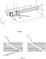
- a scanning-type inkjet printer comprises an inkjet print head 3 mounted on a print head carriage 2 arranged to move relative to a recording medium 4 along a first horizontal axis Y while being guided by a guiding structure 1.
- Scanning inkjet printers as that depicted in Fig. 1 are one of the types of printers on which the present invention may be applied.
- Either the guiding structure 1 or the recording medium 4 is movably arranged in order for the guiding structure 1 and the recording medium 4 to be moved relative to each other along a second horizontal axis X normal to the first horizontal axis Y.
- a swath of ink droplets is deposited onto the recording medium 4 by the print head 3 ejecting sequences of ink droplets towards the recording medium 4 while the print head carriage 2 is moving along the first horizontal axis Y, guided by the guiding structure 1.
- the guiding structure 1 and the recording medium 4 are moved relative to each other along the second horizontal axis X, so that multiple swaths of ink droplets deposited onto the recording medium 4 can form a complete printed image.
- the guiding structure 1 comprises an elongated main part 10, oriented to extend along the first horizontal axis Y.
- the guiding structure 1 further comprises a pair of primary guidance rails 20a, 20b, mounted above each other on a front face 11 of the main part 10 oriented orthogonally with respect to the second horizontal axis X.
- the primary guidance rails 20a, 20b extend in parallel to each other along the first horizontal axis Y, spaced apart along the vertical axis Z.
- Fig. 1 also shows two pinning lamps 5 attached to the carriage 2. Said pinning lamps are suitable for applying ultraviolet, UV, light onto ink previously deposited onto recording medium 4.
- the pinning lamp situated at the left of the carriage 2 in Fig.1 takes care of applying UV light to the ink deposited by printhead 3 while the print head carriage 2 displaces from right to left along the first horizontal axis Y, while the pinning lamp situated at the right of the carriage 2 in Fig.1 takes care of applying UV light to the ink deposited by printhead 3 while the print head carriage 2 displaces from left to right along the first horizontal axis Y.
- the present invention may be applied to scanning inkjet printers as the inkjet printer shown in Fig. 1 .
- a person skilled in the art would readily appreciate that the present invention may be however applied in any inkjet printer provided that said inkjet printer comprises at least one pinning lamp for applying ultraviolet, UV, light to a UV light-curable ink.
- Fig. 2a comprises a reference marker 21 and a test marker 22. It can be observed in Fig. 2a that the reference marker 21 and the test marker 22 are formed by a plurality of lines, wherein said lines include notches 23, understood as indentations, incisions, or discontinuities on an edge or line. Said notches are strategically placed such that the notches form a numbering system from which the different lines forming the reference marker 21 and a test marker 22 can be individually distinguished. The reference marker 21 and the test marker 22 are used to measure the calibration error.
- the reference marker 21 is printed with the first nozzles of a printhead, while the test marker 22 is printed with the last nozzles of said printhead once the media step has been performed.
- the relative error attributable to the movement of the recording medium can be reliably inferred.
- Fig. 2b shows a bit-based pattern in which the lines of a calibration marker shown in Fig. 2a are substituted by lines referred to as bits in the art, which have the characteristics of being extremely short. Said bits are formed by very short lines as indicated in Fig. 2b by the width 25 of one of the bit markers 26 of Fig. 2b .
- the marker shown in Fig. 2b uses a binary code to indicate the line number of each bit.
- element 27 is used as a binary code to indicate the line numbering.
- Fig. 2b it can be observed that the line numbering is incremented one unit for every line, the first line having a decimal value 0 and the last line having a decimal value 7, knowing that the most significant bit of element 27 is that at the left of element 27.
- Fig. 2b also indicates the distance 28 between the reference marker (left) and the test marker (right).
- the relative error attributable to the movement of the recording medium can be reliably inferred.
- FIG. 2c Another example of calibration markers used in the context of the present invention is presented. It can be observed that Fig. 2c is similar to Fig. 2a in that it displays a reference marker 21 and a test marker 22, wherein both markers contain a plurality of notches used to indicate the different line numberings.
- a plurality of see-through elements 24 can be observed, caused by the characteristics of the recording medium.
- see-through elements 24 are present whenever transparent or meshed recording media are used. Said see-through elements 24 highly increase the likelihood of misinterpretation of the calibration markers 21 and 22 by a scanner, even in the case in which there is appropriate color contrast between the markers and the recording medium.
- Fig. 2c it can be observed in Fig. 2c that the reference marker 21 and the test marker 22 lay on a non-uniform background.
- Said non-uniform background comprises the recording media onto which the reference marker 21 and the test marker 22 have been printed, as well as the background formed by see-through elements 24. This non-uniformity leads to inaccurate detection of the reference marker 21 and the test marker 22 even if a good color contrast exists between reference marker 21 and the test marker 22 and the recording medium, as explained in more detail below.
- step S1 of the method of the present invention comprises the inkjet printer printing a contrast plane on the recording medium with UV light-curable ink of a first color.
- the contrast plane printed on the recording medium in step S1 is cured in step S2 of the method of the present invention by applying ultraviolet, UV, light to the contrast plane with the pinning lamp.
- ultraviolet, UV, light to the contrast plane with the pinning lamp, the ink droplets move to a higher viscosity state, but stop short of full cure.
- This process is known in the art as gelling of a UV light-curable ink.
- This step allows a quick curing of the printed contrast plane, which in turn allows immediately printing onto the printed contrast plane, without the need of transporting the recording medium to a curing stage as commonly known in the art, in which the recording medium is transported under a plurality of UV curing lamps in order to launch a process in which ultraviolet light and visible light is used to initiate a photochemical reaction that generates a crosslinked network of polymers in the ink, reaching full cure of the UV light-curable ink.
- the inkjet printer of the present invention comprises printing a calibration marker with UV light-curable ink of a second color onto the printed contrast plane, wherein the first color and the second color have a contrast ratio higher than 1.
- the present invention allows providing a calibration marker which is easily distinguishable for a scanner from the background consisting of the contrast plane.
- printing and curing with a pinning lamp a plurality of contrast planes such that a plurality of calibration markers can be printed onto them, which improves the media steps calculations.
- the SI unit for luminance is candela per square meter (cd/m 2 ).
- the self-contrast ratio of any color is 1. In applications in which it required that an area printed in a first color must be distinguished, either by an external observer or a scanner dedicated to that task, from a second area printed in a second color it is required that a high contrast ratio exists between a first and a second color.
- Such high contrast ratio has been defined in other fields of technology as web design as at least a ratio of 4.5, in order to allow easily distinguishing by an external observer a first area in a first color from a second area in a second color.
- the inventor has determined, however, that a contrast ratio of 3 is sufficient for applications like inkjet printing, in which typically a scanner needs to distinguish between an area printed in a first color from a second area printed in a second color.
- a ratio of at least 4.5 is however preferable.
- the present invention may comprise an additional step of curing the calibration marker printed on the recording medium, more particularly onto the contrast plane printed thereon, by applying ultraviolet, UV, light to the calibration marker with the pinning lamp.
- This step provides calibration markers which do not flow out before a curing phase, and are therefore more easily recognizable for a scanner as those typically used in these applications.
- FIG. 4a an example of a prior art method for printing calibration markers is shown.
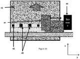
- a plurality of calibration markers 42 which have been printed onto a recording medium 43 can be observed.
- the recording medium 43 shown in Fig. 4a is meshed.
- the present invention may be applied to any recording medium for which there is a difficulty to interpret calibration markers printed thereon.
- the belt on top on which the recording medium is transported can be seen through the recording medium, which causes said belt, usually black, to be the background of the calibration markers.
- the plurality of calibration markers 42 is designed such that subsequently a scanner 44 can read them in order to calibrate the media steps needed for the recording medium 43.
- a contrast plane 45 has been printed such that it forms a uniform background for the plurality of calibration markers 42.
- the contrast plane 45 is cured by applying ultraviolet, UV, light to the contrast plane 45 with the pinning lamp of the inkjet printer. In this manner, it becomes possible to immediately print the plurality of calibration markers 42 onto the cured contrast plane 45, thereby allowing performing the complete process of printing the contrast plane and the plurality of calibration markers without delaying the printing process.
Landscapes
- Health & Medical Sciences (AREA)
- General Health & Medical Sciences (AREA)
- Toxicology (AREA)
- Engineering & Computer Science (AREA)
- Physics & Mathematics (AREA)
- Electromagnetism (AREA)
- Multimedia (AREA)
- Signal Processing (AREA)
- General Engineering & Computer Science (AREA)
- General Physics & Mathematics (AREA)
- Theoretical Computer Science (AREA)
- Ink Jet (AREA)
Abstract
Description
- The present invention generally pertains to a method for printing calibration markers in an inkjet printer.
- Media calibration is a well-known process in the art. Such methods commonly comprise printing and scanning one or more calibration markers onto a recording medium, which are used to calibrate the average value of a media step. This media calibration process is essential in order to achieve high print quality, as it minimizes undesired light and dark stripes between consecutive swaths.
- It is also known in the art that it is sometimes difficult for the inkjet printer to interpret the calibration markers which have been previously printed onto the recording medium. Said difficulty may be caused by the inkjet printer not being capable of correctly interpreting the calibration markers, especially when particular types of recording media, as transparent or meshed, are used.
- When an inkjet printer is incapable of correctly interpreting calibration markers, its media step calibration likely fails, thereby rendering the recording medium unusable by the inkjet printer.
- It is therefore needed to provide a method for printing a calibration marker that improves the readability of the calibration markers typically printed on recording media.
- In an aspect of the present invention, a method for printing calibration markers in a scanning jet printer is provided. The inkjet printer comprises a pinning lamp suitable for applying a ultraviolet, UV, light to a UV light-curable ink. The method comprises printing a contrast plane on the recording medium with UV light-curable ink of a first color. Subsequently, the method comprises at least partially curing the contrast plane printed on the recording medium by applying a ultraviolet, UV, light to the contrast plane with the pinning lamp. A full cure of the contrast plane is not needed. As a consequence, the contrast plane is usually only partially cured such that printing can be immediately performed onto the contrast plane without any detrimental effect. If deemed required, the contrast plane containing the marker can be post-cured. The use of the pinning lamp to cure the printed contrast plane, allows immediately printing a calibration marker onto the contrast plane, which improves the readability of the calibration marker. In turn, this allows the present invention to more accurately calculate reliable media steps, based on the inkjet printer scanning the printed plurality of calibration markers.
- In an embodiment, the droplets are pinned by irradiating the droplets with a radiation source, wherein the intensity of radiation provided to the ink by the radiation source is adjustable.
- Irradiation with a suitable source of radiation may be a suitable way to pin the radiation-curable phase change ink composition. Examples of suitable radiation are electron beam radiation or UV radiation. UV radiation may be suitably applied to cure UV curable ink. Example of UV radiation sources are UV lamps, such as UV LED lamps and Hg bulbs. UV LEDs are preferred, because they are energy efficient and because the intensity of the radiation emitted by UV LEDs can be easily adjusted.
- The intensity of radiation provided to the ink may be adjustable. This may be done e.g. by changing the distance between the source of radiation and the recording medium provided with ink. Alternatively and/or additionally, the intensity of the radiation emitted by the source of radiation may be adjusted.
- The intensity of the radiation emitted onto the ink by the source of radiation may be in the range of 0.5 W/cm2 - 8 W/cm2, preferably 1 W/cm2 - 4 W/cm2. Intensities of radiation between 1 W/cm2 - 4 W/cm2 are considered in the art as low dosages of radiation which, with the typical applications times of pinning lamps (imposed by the speed of the carriage over the recording medium) do not fully cure the ink. The intensity of the radiation may be measured at the surface of the recording medium. When the intensity of the radiation emitted onto the ink by the first source of radiation is lower than 0.5 W/cm2, then the pinning may be ineffective and consequently, the ink may still penetrate the recording medium. When the intensity of the radiation emitted onto the ink by the first source of radiation exceeds than 8 W/cm2, the degree of polymerization may be too high. When the degree of polymerization induced by the first radiation is too high, then the ink may be considered cured instead of pinned. Curing the ink without pinning the ink may result in decrease of gloss of the ink. As the pinning lamp is typically attached to a carriage of an inkjet printer, the application time is usually short, and depends on the speed with which the carriage travels over the recording medium.
- In the present invention, UV, light is applied to the calibration marker with the pinning lamp. As explained more in detail below, applying ultraviolet light causes the ink droplets to move to a higher viscosity state, yet said ink droplets stop short of full cure.
- In an embodiment of the method according to the present invention, the present invention further comprises comprising curing the calibration marker printed on the recording medium by applying ultraviolet, UV, light to the calibration marker with the pinning lamp.
- In an embodiment of the method according to the present invention, the present invention comprises a recording medium which is transparent or meshed.
- In an embodiment of the method according to the present invention, the inkjet printer of the present invention further comprises a scanner for scanning the calibration marker.
- In an embodiment of the method according to the present invention, the inkjet printer of the present invention is a scanning inkjet printer.
- In an embodiment of the method according to the present invention, the contrast ratio between the first color and the second color is at least 3, preferably at least 4.5.
- In an embodiment of the method according to the present invention, printing a contrast plane on the recording medium with UV light-curable ink of a first color comprises printing a plurality of contrast planes with UV light-curable ink of a first color, and wherein a calibration marker with UV light-curable is printed with ink of a second color onto each of the plurality of printed contrast planes such that each of the plurality of printed contrast planes forms a uniform background for one of the plurality of printed calibration markers. This embodiment allows printing a plurality of calibration markers for which a contrast plane acts as a uniform background, thereby improving the readability of said plurality of calibration markers. Further, it allows detecting and correcting misalignments of recording media.
- Further scope of applicability of the present invention will become apparent from the detailed description given hereinafter. However, it should be understood that the detailed description and specific examples, while indicating embodiments of the invention, are given by way of illustration only, since various changes and modifications within the scope of the invention will become apparent to those skilled in the art from this detailed description.
- The present invention will become more fully understood from the detailed description given herein below and the accompanying schematic drawings which are given by way of illustration only, and thus are not limitative of the present invention, and wherein:
- Fig. 1
- shows a schematic perspective view of an assembly of a guiding structure and a print head carriage in a scanning-type printer, the print head carriage carrying a print head;
- Fig. 2a
- shows an example of calibration markers used in the context of the present invention;
- Fig. 2b
- shows an additional example of calibration markers used in the context of the present invention;
- Fig. 2c
- shows another example of calibration markers used in the context of the present invention;
- Fig. 3
- is a flow diagram of the method of the present invention;
- Fig. 4a
- shows an example of the a prior art method for printing calibration markers;
- Fig. 4b
- shows an example of the method of the present invention for printing calibration markers;
- The present invention will now be described with reference to the accompanying drawings, wherein the same reference numerals have been used to identify the same or similar elements throughout the several views.
- With reference to
Fig. 1 , a scanning-type inkjet printer comprises aninkjet print head 3 mounted on aprint head carriage 2 arranged to move relative to a recording medium 4 along a first horizontal axis Y while being guided by a guidingstructure 1. Scanning inkjet printers as that depicted inFig. 1 are one of the types of printers on which the present invention may be applied. - Either the guiding
structure 1 or the recording medium 4 is movably arranged in order for the guidingstructure 1 and the recording medium 4 to be moved relative to each other along a second horizontal axis X normal to the first horizontal axis Y. - In operation, a swath of ink droplets is deposited onto the recording medium 4 by the
print head 3 ejecting sequences of ink droplets towards the recording medium 4 while theprint head carriage 2 is moving along the first horizontal axis Y, guided by the guidingstructure 1. - In between the deposition of different swaths, the guiding
structure 1 and the recording medium 4 are moved relative to each other along the second horizontal axis X, so that multiple swaths of ink droplets deposited onto the recording medium 4 can form a complete printed image. - In the shown embodiment, the guiding
structure 1 comprises an elongatedmain part 10, oriented to extend along the first horizontal axis Y. - The guiding
structure 1 further comprises a pair ofprimary guidance rails front face 11 of themain part 10 oriented orthogonally with respect to the second horizontal axis X. Theprimary guidance rails -
Fig. 1 also shows two pinninglamps 5 attached to thecarriage 2. Said pinning lamps are suitable for applying ultraviolet, UV, light onto ink previously deposited onto recording medium 4. The pinning lamp situated at the left of thecarriage 2 inFig.1 takes care of applying UV light to the ink deposited byprinthead 3 while theprint head carriage 2 displaces from right to left along the first horizontal axis Y, while the pinning lamp situated at the right of thecarriage 2 inFig.1 takes care of applying UV light to the ink deposited byprinthead 3 while theprint head carriage 2 displaces from left to right along the first horizontal axis Y. - The present invention may be applied to scanning inkjet printers as the inkjet printer shown in
Fig. 1 . A person skilled in the art would readily appreciate that the present invention may be however applied in any inkjet printer provided that said inkjet printer comprises at least one pinning lamp for applying ultraviolet, UV, light to a UV light-curable ink. - With reference to
Fig. 2a , an example of calibration markers used in the context of the present invention is shown.Fig. 2a comprises areference marker 21 and atest marker 22. It can be observed inFig. 2a that thereference marker 21 and thetest marker 22 are formed by a plurality of lines, wherein said lines includenotches 23, understood as indentations, incisions, or discontinuities on an edge or line. Said notches are strategically placed such that the notches form a numbering system from which the different lines forming thereference marker 21 and atest marker 22 can be individually distinguished. Thereference marker 21 and thetest marker 22 are used to measure the calibration error. In order to do so, thereference marker 21 is printed with the first nozzles of a printhead, while thetest marker 22 is printed with the last nozzles of said printhead once the media step has been performed. As the information about their position is known beforehand, the relative error attributable to the movement of the recording medium can be reliably inferred. - It is known in the art
printing reference marker 21 andtest marker 22 using colors with an intense color contrast with the recording medium. Further, it is also known using light of different predominant wavelengths in order to facilitate the scanning of the calibration markers. For example, it is known using a predominantly yellow light to illuminate yellow markers printed onto a predominantly white recording medium. In this way, the markers absorb most of the emitted light, which improves the accuracy of the scanning process. These techniques do not allow, however, accurately detecting calibration markers printed on transparent or meshed media, as it is better understood in relation with the explanations related toFig. 2c andFig. 4b below. - With reference to
Fig. 2b , an additional example of calibration markers used in the context of the present invention is shown.Fig. 2b shows a bit-based pattern in which the lines of a calibration marker shown inFig. 2a are substituted by lines referred to as bits in the art, which have the characteristics of being extremely short. Said bits are formed by very short lines as indicated inFig. 2b by thewidth 25 of one of thebit markers 26 ofFig. 2b . Instead of notches, as in the example ofFig. 2a , the marker shown inFig. 2b uses a binary code to indicate the line number of each bit. InFig. 2b ,element 27 is used as a binary code to indicate the line numbering. In the pattern ofFig. 2b , it can be observed that the line numbering is incremented one unit for every line, the first line having a decimal value 0 and the last line having a decimal value 7, knowing that the most significant bit ofelement 27 is that at the left ofelement 27.Fig. 2b also indicates thedistance 28 between the reference marker (left) and the test marker (right). Similarly toFig. 2a , as the information about their position is known beforehand, the relative error attributable to the movement of the recording medium can be reliably inferred. - With reference to
Fig. 2c , another example of calibration markers used in the context of the present invention is presented. It can be observed thatFig. 2c is similar toFig. 2a in that it displays areference marker 21 and atest marker 22, wherein both markers contain a plurality of notches used to indicate the different line numberings. InFig. 2c , a plurality of see-throughelements 24 can be observed, caused by the characteristics of the recording medium. A person skilled in the art would readily understand that see-throughelements 24 are present whenever transparent or meshed recording media are used. Said see-throughelements 24 highly increase the likelihood of misinterpretation of thecalibration markers - A person skilled in the art would readily understand that the considerations related to
Fig. 2c similarly apply to the calibration markers referred to inFig. 2b , as well as to any other calibration marker typically used in the art. - It can be observed in
Fig. 2c that thereference marker 21 and thetest marker 22 lay on a non-uniform background. Said non-uniform background comprises the recording media onto which thereference marker 21 and thetest marker 22 have been printed, as well as the background formed by see-throughelements 24. This non-uniformity leads to inaccurate detection of thereference marker 21 and thetest marker 22 even if a good color contrast exists betweenreference marker 21 and thetest marker 22 and the recording medium, as explained in more detail below. - With reference to
Fig. 3 , a flow diagram of the method of the present invention is presented. - In the present invention, step S1 of the method of the present invention comprises the inkjet printer printing a contrast plane on the recording medium with UV light-curable ink of a first color.
- Subsequently, the contrast plane printed on the recording medium in step S1 is cured in step S2 of the method of the present invention by applying ultraviolet, UV, light to the contrast plane with the pinning lamp. As a result of the application of ultraviolet, UV, light to the contrast plane with the pinning lamp, the ink droplets move to a higher viscosity state, but stop short of full cure. This process is known in the art as gelling of a UV light-curable ink. This step allows a quick curing of the printed contrast plane, which in turn allows immediately printing onto the printed contrast plane, without the need of transporting the recording medium to a curing stage as commonly known in the art, in which the recording medium is transported under a plurality of UV curing lamps in order to launch a process in which ultraviolet light and visible light is used to initiate a photochemical reaction that generates a crosslinked network of polymers in the ink, reaching full cure of the UV light-curable ink.
- Next, in step S3 the inkjet printer of the present invention comprises printing a calibration marker with UV light-curable ink of a second color onto the printed contrast plane, wherein the first color and the second color have a contrast ratio higher than 1. In this way, the present invention allows providing a calibration marker which is easily distinguishable for a scanner from the background consisting of the contrast plane. A person skilled in the art would readily understand that it is within the scope of the present invention printing and curing with a pinning lamp a plurality of contrast planes such that a plurality of calibration markers can be printed onto them, which improves the media steps calculations.
- The contrast ratio between two colors can be defined as the ratio of the luminance of the brightest color to that of the darkest color, as shown in Equation 1:

- Therefore, the self-contrast ratio of any color is 1. In applications in which it required that an area printed in a first color must be distinguished, either by an external observer or a scanner dedicated to that task, from a second area printed in a second color it is required that a high contrast ratio exists between a first and a second color.
- Such high contrast ratio has been defined in other fields of technology as web design as at least a ratio of 4.5, in order to allow easily distinguishing by an external observer a first area in a first color from a second area in a second color. The inventor has determined, however, that a contrast ratio of 3 is sufficient for applications like inkjet printing, in which typically a scanner needs to distinguish between an area printed in a first color from a second area printed in a second color. A ratio of at least 4.5 is however preferable.
- However, as explained above, it is not enough selecting an appropriate color contrast ratio to improve the detection of calibration markers, as non-uniformities in the background, typical in meshed or transparent media, hinder the readability of the calibration markers.
- Optionally, the present invention may comprise an additional step of curing the calibration marker printed on the recording medium, more particularly onto the contrast plane printed thereon, by applying ultraviolet, UV, light to the calibration marker with the pinning lamp. This step provides calibration markers which do not flow out before a curing phase, and are therefore more easily recognizable for a scanner as those typically used in these applications.
- With reference to
Fig. 4a , an example of a prior art method for printing calibration markers is shown. - In
Fig. 4a a plurality ofcalibration markers 42 which have been printed onto arecording medium 43 can be observed. As a mere example, therecording medium 43 shown inFig. 4a is meshed. A person skilled in the art would readily understand that the present invention may be applied to any recording medium for which there is a difficulty to interpret calibration markers printed thereon. For example, when a transparent recording medium is used, the belt on top on which the recording medium is transported can be seen through the recording medium, which causes said belt, usually black, to be the background of the calibration markers. The plurality ofcalibration markers 42 is designed such that subsequently ascanner 44 can read them in order to calibrate the media steps needed for therecording medium 43. - It can be observed in
Fig. 4a , and it becomes clearer in the explanation ofFig. 4b below, that there is an insufficient contrast between the printedcalibration markers 42 and the background formed by therecording medium 43, thereby causing a difficulty for ascanner 44 on the inkjet printer to interpret the calibration markers when calculating media steps for every swath. - With reference to
Fig. 4b , an example of the method of the present invention for printing calibration markers is shown. It can be observed inFig. 4b that acontrast plane 45 has been printed such that it forms a uniform background for the plurality ofcalibration markers 42. It should be noted that in the method of the present invention thecontrast plane 45 is cured by applying ultraviolet, UV, light to thecontrast plane 45 with the pinning lamp of the inkjet printer. In this manner, it becomes possible to immediately print the plurality ofcalibration markers 42 onto the curedcontrast plane 45, thereby allowing performing the complete process of printing the contrast plane and the plurality of calibration markers without delaying the printing process. Also, it becomes possible performing a media step, in which the media is advance for printing of the next swath, immediately after printing one or more calibration markers. These steps of the present invention allow avoiding a stall to wait for the recording medium to be transported to a curing stage and be brought back to the printing stage. - Detailed embodiments of the present invention are disclosed herein; however, it is to be understood that the disclosed embodiments are merely exemplary of the invention, which can be embodied in various forms. Therefore, specific structural and functional details disclosed herein are not to be interpreted as limiting, but merely as a basis for the claims and as a representative basis for teaching one skilled in the art to variously employ the present invention in virtually any appropriately detailed structure. In particular, features presented and described in separate dependent claims may be applied in combination and any advantageous combination of such claims is herewith disclosed.
- Further, the terms and phrases used herein are not intended to be limiting; but rather, to provide an understandable description of the invention. The terms "a" or "an", as used herein, are defined as one or more than one. The term plurality, as used herein, is defined as two or more than two. The term another, as used herein, is defined as at least a second or more. The terms including and/or having, as used herein, are defined as comprising (i.e., open language).
- The invention being thus described, it will be obvious that the same may be varied in many ways. Such variations are not to be regarded as a departure from the spirit and scope of the invention, and all such modifications as would be obvious to one skilled in the art are intended to be included within the scope of the following claims.
Claims (8)
- A method for printing calibration markers in an inkjet printer, the inkjet printer comprising a pinning lamp suitable for applying ultraviolet, UV, light to a UV light-curable ink, the method comprising:printing a contrast plane on the recording medium with UV light-curable ink of a first color;at least partially curing the contrast plane printed on the recording medium by applying ultraviolet, UV, light to the contrast plane with the pinning lamp;printing a calibration marker with UV light-curable ink of a second color onto the printed contrast plane such that the printed contrast plane forms a uniform background for the printed calibration marker, wherein the first color and the second color have a contrast ratio higher than 1.
- The method according to claim 1,further comprising curing the calibration marker printed on the recording medium by applying ultraviolet, UV, light to the plurality of calibration markers with the pinning lamp.
- The method of claim 1, wherein the recording medium is transparent or meshed.
- The method of any of the preceding claims, wherein the inkjet printer further comprises a scanner for scanning the calibration marker.
- The method of any of the preceding claims, wherein the inkjet printer is a scanning inkjet printer.
- The method of any of the preceding claims, wherein the contrast ratio between the first color and the second color is at least 3, preferably at least 4.5.
- The method of any of the preceding claims, wherein printing a contrast plane on the recording medium with UV light-curable ink of a first color comprises printing a plurality of contrast planes with UV light-curable ink of a first color, and wherein a calibration marker with UV light-curable is printed with ink of a second color onto each of the plurality of printed contrast planes such that each of the plurality of printed contrast planes forms a uniform background for one of the plurality of printed calibration markers.
- The method of any of the preceding claims, wherein applying ultraviolet, UV, light to a UV light-curable ink comprises applying an intensity of the radiation emitted onto the ink range of 0.5 W/cm2 - 8 W/cm2, preferably 1 W/cm2 - 4 W/cm2.
Applications Claiming Priority (1)
| Application Number | Priority Date | Filing Date | Title |
|---|---|---|---|
| EP18195812 | 2018-09-20 |
Publications (2)
| Publication Number | Publication Date |
|---|---|
| EP3626468A1 true EP3626468A1 (en) | 2020-03-25 |
| EP3626468B1 EP3626468B1 (en) | 2022-08-24 |
Family
ID=63667829
Family Applications (1)
| Application Number | Title | Priority Date | Filing Date |
|---|---|---|---|
| EP18202598.1A Active EP3626468B1 (en) | 2018-09-20 | 2018-10-25 | Method for printing calibration markers in inkjet printers |
Country Status (1)
| Country | Link |
|---|---|
| EP (1) | EP3626468B1 (en) |
Cited By (1)
| Publication number | Priority date | Publication date | Assignee | Title |
|---|---|---|---|---|
| WO2022024347A1 (en) * | 2020-07-31 | 2022-02-03 | コニカミノルタ株式会社 | Image formation device |
Citations (3)
| Publication number | Priority date | Publication date | Assignee | Title |
|---|---|---|---|---|
| US20040179217A1 (en) * | 2003-03-14 | 2004-09-16 | Chapman Alexander L. | Methods and systems to calibrate media indexing errors in a printing device |
| EP2960062A1 (en) * | 2014-06-26 | 2015-12-30 | OCE-Technologies B.V. | Method for calibrating accurate paper steps |
| US20170341416A1 (en) * | 2016-05-27 | 2017-11-30 | Xerox Corporation | Method of single pass printing of multiple colors |
-
2018
- 2018-10-25 EP EP18202598.1A patent/EP3626468B1/en active Active
Patent Citations (3)
| Publication number | Priority date | Publication date | Assignee | Title |
|---|---|---|---|---|
| US20040179217A1 (en) * | 2003-03-14 | 2004-09-16 | Chapman Alexander L. | Methods and systems to calibrate media indexing errors in a printing device |
| EP2960062A1 (en) * | 2014-06-26 | 2015-12-30 | OCE-Technologies B.V. | Method for calibrating accurate paper steps |
| US20170341416A1 (en) * | 2016-05-27 | 2017-11-30 | Xerox Corporation | Method of single pass printing of multiple colors |
Cited By (1)
| Publication number | Priority date | Publication date | Assignee | Title |
|---|---|---|---|---|
| WO2022024347A1 (en) * | 2020-07-31 | 2022-02-03 | コニカミノルタ株式会社 | Image formation device |
Also Published As
| Publication number | Publication date |
|---|---|
| EP3626468B1 (en) | 2022-08-24 |
Similar Documents
| Publication | Publication Date | Title |
|---|---|---|
| CN102470668B (en) | Inkjet printer and inkjet printing method | |
| US6536889B1 (en) | Systems and methods for ejecting or depositing substances containing multiple photointiators | |
| US20170050449A1 (en) | Printing method and printing device | |
| CN104136224B (en) | Apparatus and method for single pass inkjet printing | |
| US8814343B2 (en) | Liquid ejecting apparatus | |
| KR101782167B1 (en) | Method and apparatus for forming an image on a substrate in printing | |
| US8827403B2 (en) | Printing apparatus and printing method | |
| US20110050822A1 (en) | Printing system | |
| US20120223982A1 (en) | Printing device and printing method | |
| EP2956309B1 (en) | Formation of gloss level areas having a glossy finish and a matte finish in an image | |
| US8936337B2 (en) | Method of adding gloss control table | |
| US10695974B2 (en) | Three-dimensional object shaping method and three-dimensional object shaping device | |
| EP3626468B1 (en) | Method for printing calibration markers in inkjet printers | |
| US20060038868A1 (en) | Printing device with radiation source | |
| JP2017209990A (en) | Method of single pass printing of multiple colors | |
| JP5782984B2 (en) | Printing apparatus and printing method | |
| US11458741B2 (en) | Method for applying an image | |
| US7497553B2 (en) | Inkjet recording method and inkjet recording apparatus | |
| ES2656312T3 (en) | Ctp inkjet procedure for the preparation of a set of lithographic printing plates | |
| US20160140790A1 (en) | Method and device for marking value labels | |
| JP2013086429A (en) | Printing apparatus and printing method | |
| US20230049833A1 (en) | Inkjet printing apparatus | |
| US10341506B2 (en) | Calibrated print data generation based on color calibration data accounting for backlight characteristics | |
| US20250026075A1 (en) | Inkjet printing method and inkjet printing device | |
| JP2011218576A (en) | Density correction method and printer |
Legal Events
| Date | Code | Title | Description |
|---|---|---|---|
| PUAI | Public reference made under article 153(3) epc to a published international application that has entered the european phase |
Free format text: ORIGINAL CODE: 0009012 |
|
| STAA | Information on the status of an ep patent application or granted ep patent |
Free format text: STATUS: THE APPLICATION HAS BEEN PUBLISHED |
|
| AK | Designated contracting states |
Kind code of ref document: A1 Designated state(s): AL AT BE BG CH CY CZ DE DK EE ES FI FR GB GR HR HU IE IS IT LI LT LU LV MC MK MT NL NO PL PT RO RS SE SI SK SM TR |
|
| AX | Request for extension of the european patent |
Extension state: BA ME |
|
| STAA | Information on the status of an ep patent application or granted ep patent |
Free format text: STATUS: REQUEST FOR EXAMINATION WAS MADE |
|
| 17P | Request for examination filed |
Effective date: 20200925 |
|
| RBV | Designated contracting states (corrected) |
Designated state(s): AL AT BE BG CH CY CZ DE DK EE ES FI FR GB GR HR HU IE IS IT LI LT LU LV MC MK MT NL NO PL PT RO RS SE SI SK SM TR |
|
| RAP1 | Party data changed (applicant data changed or rights of an application transferred) |
Owner name: CANON PRODUCTION PRINTING HOLDING B.V. |
|
| GRAP | Despatch of communication of intention to grant a patent |
Free format text: ORIGINAL CODE: EPIDOSNIGR1 |
|
| STAA | Information on the status of an ep patent application or granted ep patent |
Free format text: STATUS: GRANT OF PATENT IS INTENDED |
|
| INTG | Intention to grant announced |
Effective date: 20220331 |
|
| GRAS | Grant fee paid |
Free format text: ORIGINAL CODE: EPIDOSNIGR3 |
|
| GRAA | (expected) grant |
Free format text: ORIGINAL CODE: 0009210 |
|
| STAA | Information on the status of an ep patent application or granted ep patent |
Free format text: STATUS: THE PATENT HAS BEEN GRANTED |
|
| AK | Designated contracting states |
Kind code of ref document: B1 Designated state(s): AL AT BE BG CH CY CZ DE DK EE ES FI FR GB GR HR HU IE IS IT LI LT LU LV MC MK MT NL NO PL PT RO RS SE SI SK SM TR |
|
| REG | Reference to a national code |
Ref country code: CH Ref legal event code: EP |
|
| REG | Reference to a national code |
Ref country code: IE Ref legal event code: FG4D |
|
| REG | Reference to a national code |
Ref country code: AT Ref legal event code: REF Ref document number: 1513390 Country of ref document: AT Kind code of ref document: T Effective date: 20220915 Ref country code: DE Ref legal event code: R096 Ref document number: 602018039628 Country of ref document: DE |
|
| REG | Reference to a national code |
Ref country code: NL Ref legal event code: FP |
|
| REG | Reference to a national code |
Ref country code: LT Ref legal event code: MG9D |
|
| PG25 | Lapsed in a contracting state [announced via postgrant information from national office to epo] |
Ref country code: SE Free format text: LAPSE BECAUSE OF FAILURE TO SUBMIT A TRANSLATION OF THE DESCRIPTION OR TO PAY THE FEE WITHIN THE PRESCRIBED TIME-LIMIT Effective date: 20220824 Ref country code: RS Free format text: LAPSE BECAUSE OF FAILURE TO SUBMIT A TRANSLATION OF THE DESCRIPTION OR TO PAY THE FEE WITHIN THE PRESCRIBED TIME-LIMIT Effective date: 20220824 Ref country code: PT Free format text: LAPSE BECAUSE OF FAILURE TO SUBMIT A TRANSLATION OF THE DESCRIPTION OR TO PAY THE FEE WITHIN THE PRESCRIBED TIME-LIMIT Effective date: 20221226 Ref country code: NO Free format text: LAPSE BECAUSE OF FAILURE TO SUBMIT A TRANSLATION OF THE DESCRIPTION OR TO PAY THE FEE WITHIN THE PRESCRIBED TIME-LIMIT Effective date: 20221124 Ref country code: LV Free format text: LAPSE BECAUSE OF FAILURE TO SUBMIT A TRANSLATION OF THE DESCRIPTION OR TO PAY THE FEE WITHIN THE PRESCRIBED TIME-LIMIT Effective date: 20220824 Ref country code: LT Free format text: LAPSE BECAUSE OF FAILURE TO SUBMIT A TRANSLATION OF THE DESCRIPTION OR TO PAY THE FEE WITHIN THE PRESCRIBED TIME-LIMIT Effective date: 20220824 Ref country code: FI Free format text: LAPSE BECAUSE OF FAILURE TO SUBMIT A TRANSLATION OF THE DESCRIPTION OR TO PAY THE FEE WITHIN THE PRESCRIBED TIME-LIMIT Effective date: 20220824 |
|
| REG | Reference to a national code |
Ref country code: AT Ref legal event code: MK05 Ref document number: 1513390 Country of ref document: AT Kind code of ref document: T Effective date: 20220824 |
|
| PG25 | Lapsed in a contracting state [announced via postgrant information from national office to epo] |
Ref country code: PL Free format text: LAPSE BECAUSE OF FAILURE TO SUBMIT A TRANSLATION OF THE DESCRIPTION OR TO PAY THE FEE WITHIN THE PRESCRIBED TIME-LIMIT Effective date: 20220824 Ref country code: IS Free format text: LAPSE BECAUSE OF FAILURE TO SUBMIT A TRANSLATION OF THE DESCRIPTION OR TO PAY THE FEE WITHIN THE PRESCRIBED TIME-LIMIT Effective date: 20221224 Ref country code: HR Free format text: LAPSE BECAUSE OF FAILURE TO SUBMIT A TRANSLATION OF THE DESCRIPTION OR TO PAY THE FEE WITHIN THE PRESCRIBED TIME-LIMIT Effective date: 20220824 Ref country code: GR Free format text: LAPSE BECAUSE OF FAILURE TO SUBMIT A TRANSLATION OF THE DESCRIPTION OR TO PAY THE FEE WITHIN THE PRESCRIBED TIME-LIMIT Effective date: 20221125 |
|
| PG25 | Lapsed in a contracting state [announced via postgrant information from national office to epo] |
Ref country code: SM Free format text: LAPSE BECAUSE OF FAILURE TO SUBMIT A TRANSLATION OF THE DESCRIPTION OR TO PAY THE FEE WITHIN THE PRESCRIBED TIME-LIMIT Effective date: 20220824 Ref country code: RO Free format text: LAPSE BECAUSE OF FAILURE TO SUBMIT A TRANSLATION OF THE DESCRIPTION OR TO PAY THE FEE WITHIN THE PRESCRIBED TIME-LIMIT Effective date: 20220824 Ref country code: ES Free format text: LAPSE BECAUSE OF FAILURE TO SUBMIT A TRANSLATION OF THE DESCRIPTION OR TO PAY THE FEE WITHIN THE PRESCRIBED TIME-LIMIT Effective date: 20220824 Ref country code: DK Free format text: LAPSE BECAUSE OF FAILURE TO SUBMIT A TRANSLATION OF THE DESCRIPTION OR TO PAY THE FEE WITHIN THE PRESCRIBED TIME-LIMIT Effective date: 20220824 Ref country code: CZ Free format text: LAPSE BECAUSE OF FAILURE TO SUBMIT A TRANSLATION OF THE DESCRIPTION OR TO PAY THE FEE WITHIN THE PRESCRIBED TIME-LIMIT Effective date: 20220824 Ref country code: AT Free format text: LAPSE BECAUSE OF FAILURE TO SUBMIT A TRANSLATION OF THE DESCRIPTION OR TO PAY THE FEE WITHIN THE PRESCRIBED TIME-LIMIT Effective date: 20220824 |
|
| REG | Reference to a national code |
Ref country code: DE Ref legal event code: R097 Ref document number: 602018039628 Country of ref document: DE |
|
| PG25 | Lapsed in a contracting state [announced via postgrant information from national office to epo] |
Ref country code: SK Free format text: LAPSE BECAUSE OF FAILURE TO SUBMIT A TRANSLATION OF THE DESCRIPTION OR TO PAY THE FEE WITHIN THE PRESCRIBED TIME-LIMIT Effective date: 20220824 Ref country code: MC Free format text: LAPSE BECAUSE OF FAILURE TO SUBMIT A TRANSLATION OF THE DESCRIPTION OR TO PAY THE FEE WITHIN THE PRESCRIBED TIME-LIMIT Effective date: 20220824 Ref country code: EE Free format text: LAPSE BECAUSE OF FAILURE TO SUBMIT A TRANSLATION OF THE DESCRIPTION OR TO PAY THE FEE WITHIN THE PRESCRIBED TIME-LIMIT Effective date: 20220824 |
|
| REG | Reference to a national code |
Ref country code: CH Ref legal event code: PL |
|
| REG | Reference to a national code |
Ref country code: BE Ref legal event code: MM Effective date: 20221031 |
|
| PG25 | Lapsed in a contracting state [announced via postgrant information from national office to epo] |
Ref country code: LU Free format text: LAPSE BECAUSE OF NON-PAYMENT OF DUE FEES Effective date: 20221025 Ref country code: AL Free format text: LAPSE BECAUSE OF FAILURE TO SUBMIT A TRANSLATION OF THE DESCRIPTION OR TO PAY THE FEE WITHIN THE PRESCRIBED TIME-LIMIT Effective date: 20220824 |
|
| PLBE | No opposition filed within time limit |
Free format text: ORIGINAL CODE: 0009261 |
|
| STAA | Information on the status of an ep patent application or granted ep patent |
Free format text: STATUS: NO OPPOSITION FILED WITHIN TIME LIMIT |
|
| GBPC | Gb: european patent ceased through non-payment of renewal fee |
Effective date: 20221124 |
|
| PG25 | Lapsed in a contracting state [announced via postgrant information from national office to epo] |
Ref country code: LI Free format text: LAPSE BECAUSE OF NON-PAYMENT OF DUE FEES Effective date: 20221031 Ref country code: FR Free format text: LAPSE BECAUSE OF NON-PAYMENT OF DUE FEES Effective date: 20221031 Ref country code: CH Free format text: LAPSE BECAUSE OF NON-PAYMENT OF DUE FEES Effective date: 20221031 |
|
| 26N | No opposition filed |
Effective date: 20230525 |
|
| PG25 | Lapsed in a contracting state [announced via postgrant information from national office to epo] |
Ref country code: SI Free format text: LAPSE BECAUSE OF FAILURE TO SUBMIT A TRANSLATION OF THE DESCRIPTION OR TO PAY THE FEE WITHIN THE PRESCRIBED TIME-LIMIT Effective date: 20220824 |
|
| PG25 | Lapsed in a contracting state [announced via postgrant information from national office to epo] |
Ref country code: BE Free format text: LAPSE BECAUSE OF NON-PAYMENT OF DUE FEES Effective date: 20221031 |
|
| PG25 | Lapsed in a contracting state [announced via postgrant information from national office to epo] |
Ref country code: IE Free format text: LAPSE BECAUSE OF NON-PAYMENT OF DUE FEES Effective date: 20221025 Ref country code: GB Free format text: LAPSE BECAUSE OF NON-PAYMENT OF DUE FEES Effective date: 20221124 |
|
| PG25 | Lapsed in a contracting state [announced via postgrant information from national office to epo] |
Ref country code: HU Free format text: LAPSE BECAUSE OF FAILURE TO SUBMIT A TRANSLATION OF THE DESCRIPTION OR TO PAY THE FEE WITHIN THE PRESCRIBED TIME-LIMIT; INVALID AB INITIO Effective date: 20181025 |
|
| PG25 | Lapsed in a contracting state [announced via postgrant information from national office to epo] |
Ref country code: CY Free format text: LAPSE BECAUSE OF FAILURE TO SUBMIT A TRANSLATION OF THE DESCRIPTION OR TO PAY THE FEE WITHIN THE PRESCRIBED TIME-LIMIT Effective date: 20220824 |
|
| PG25 | Lapsed in a contracting state [announced via postgrant information from national office to epo] |
Ref country code: MK Free format text: LAPSE BECAUSE OF FAILURE TO SUBMIT A TRANSLATION OF THE DESCRIPTION OR TO PAY THE FEE WITHIN THE PRESCRIBED TIME-LIMIT Effective date: 20220824 Ref country code: IT Free format text: LAPSE BECAUSE OF FAILURE TO SUBMIT A TRANSLATION OF THE DESCRIPTION OR TO PAY THE FEE WITHIN THE PRESCRIBED TIME-LIMIT Effective date: 20220824 |
|
| PG25 | Lapsed in a contracting state [announced via postgrant information from national office to epo] |
Ref country code: BG Free format text: LAPSE BECAUSE OF FAILURE TO SUBMIT A TRANSLATION OF THE DESCRIPTION OR TO PAY THE FEE WITHIN THE PRESCRIBED TIME-LIMIT Effective date: 20220824 |
|
| PG25 | Lapsed in a contracting state [announced via postgrant information from national office to epo] |
Ref country code: MT Free format text: LAPSE BECAUSE OF FAILURE TO SUBMIT A TRANSLATION OF THE DESCRIPTION OR TO PAY THE FEE WITHIN THE PRESCRIBED TIME-LIMIT Effective date: 20220824 |
|
| PGFP | Annual fee paid to national office [announced via postgrant information from national office to epo] |
Ref country code: NL Payment date: 20250926 Year of fee payment: 8 |
|
| PG25 | Lapsed in a contracting state [announced via postgrant information from national office to epo] |
Ref country code: TR Free format text: LAPSE BECAUSE OF FAILURE TO SUBMIT A TRANSLATION OF THE DESCRIPTION OR TO PAY THE FEE WITHIN THE PRESCRIBED TIME-LIMIT Effective date: 20220824 |
|
| PGFP | Annual fee paid to national office [announced via postgrant information from national office to epo] |
Ref country code: DE Payment date: 20251021 Year of fee payment: 8 |