EP3626410A1 - Operation device - Google Patents
Operation device Download PDFInfo
- Publication number
- EP3626410A1 EP3626410A1 EP18802432.7A EP18802432A EP3626410A1 EP 3626410 A1 EP3626410 A1 EP 3626410A1 EP 18802432 A EP18802432 A EP 18802432A EP 3626410 A1 EP3626410 A1 EP 3626410A1
- Authority
- EP
- European Patent Office
- Prior art keywords
- arm
- manipulating device
- base
- parts
- arm part
- Prior art date
- Legal status (The legal status is an assumption and is not a legal conclusion. Google has not performed a legal analysis and makes no representation as to the accuracy of the status listed.)
- Granted
Links
Images







Classifications
-
- B—PERFORMING OPERATIONS; TRANSPORTING
- B25—HAND TOOLS; PORTABLE POWER-DRIVEN TOOLS; MANIPULATORS
- B25J—MANIPULATORS; CHAMBERS PROVIDED WITH MANIPULATION DEVICES
- B25J9/00—Program-controlled manipulators
- B25J9/003—Program-controlled manipulators having parallel kinematics
- B25J9/0045—Program-controlled manipulators having parallel kinematics with kinematics chains having a rotary joint at the base
- B25J9/0051—Program-controlled manipulators having parallel kinematics with kinematics chains having a rotary joint at the base with kinematics chains of the type rotary-universal-universal or rotary-spherical-spherical, e.g. Delta type manipulators
-
- G—PHYSICS
- G05—CONTROLLING; REGULATING
- G05G—CONTROL DEVICES OR SYSTEMS INSOFAR AS CHARACTERISED BY MECHANICAL FEATURES ONLY
- G05G9/00—Manually-actuated control mechanisms provided with one single controlling member co-operating with two or more controlled members, e.g. selectively, simultaneously
- G05G9/02—Manually-actuated control mechanisms provided with one single controlling member co-operating with two or more controlled members, e.g. selectively, simultaneously the controlling member being movable in different independent ways, movement in each individual way actuating one controlled member only
- G05G9/04—Manually-actuated control mechanisms provided with one single controlling member co-operating with two or more controlled members, e.g. selectively, simultaneously the controlling member being movable in different independent ways, movement in each individual way actuating one controlled member only in which movement in two or more ways can occur simultaneously
- G05G9/047—Manually-actuated control mechanisms provided with one single controlling member co-operating with two or more controlled members, e.g. selectively, simultaneously the controlling member being movable in different independent ways, movement in each individual way actuating one controlled member only in which movement in two or more ways can occur simultaneously the controlling member being movable by hand about orthogonal axes, e.g. joysticks
- G05G9/04737—Manually-actuated control mechanisms provided with one single controlling member co-operating with two or more controlled members, e.g. selectively, simultaneously the controlling member being movable in different independent ways, movement in each individual way actuating one controlled member only in which movement in two or more ways can occur simultaneously the controlling member being movable by hand about orthogonal axes, e.g. joysticks with six degrees of freedom
-
- B—PERFORMING OPERATIONS; TRANSPORTING
- B25—HAND TOOLS; PORTABLE POWER-DRIVEN TOOLS; MANIPULATORS
- B25J—MANIPULATORS; CHAMBERS PROVIDED WITH MANIPULATION DEVICES
- B25J13/00—Controls for manipulators
- B25J13/02—Hand grip control means
-
- F—MECHANICAL ENGINEERING; LIGHTING; HEATING; WEAPONS; BLASTING
- F16—ENGINEERING ELEMENTS AND UNITS; GENERAL MEASURES FOR PRODUCING AND MAINTAINING EFFECTIVE FUNCTIONING OF MACHINES OR INSTALLATIONS; THERMAL INSULATION IN GENERAL
- F16H—GEARING
- F16H21/00—Gearings comprising primarily only links or levers, with or without slides
- F16H21/46—Gearings comprising primarily only links or levers, with or without slides with movements in three dimensions [3D]
-
- G—PHYSICS
- G05—CONTROLLING; REGULATING
- G05G—CONTROL DEVICES OR SYSTEMS INSOFAR AS CHARACTERISED BY MECHANICAL FEATURES ONLY
- G05G9/00—Manually-actuated control mechanisms provided with one single controlling member co-operating with two or more controlled members, e.g. selectively, simultaneously
- G05G9/02—Manually-actuated control mechanisms provided with one single controlling member co-operating with two or more controlled members, e.g. selectively, simultaneously the controlling member being movable in different independent ways, movement in each individual way actuating one controlled member only
- G05G9/04—Manually-actuated control mechanisms provided with one single controlling member co-operating with two or more controlled members, e.g. selectively, simultaneously the controlling member being movable in different independent ways, movement in each individual way actuating one controlled member only in which movement in two or more ways can occur simultaneously
-
- G—PHYSICS
- G05—CONTROLLING; REGULATING
- G05G—CONTROL DEVICES OR SYSTEMS INSOFAR AS CHARACTERISED BY MECHANICAL FEATURES ONLY
- G05G9/00—Manually-actuated control mechanisms provided with one single controlling member co-operating with two or more controlled members, e.g. selectively, simultaneously
- G05G9/02—Manually-actuated control mechanisms provided with one single controlling member co-operating with two or more controlled members, e.g. selectively, simultaneously the controlling member being movable in different independent ways, movement in each individual way actuating one controlled member only
- G05G9/04—Manually-actuated control mechanisms provided with one single controlling member co-operating with two or more controlled members, e.g. selectively, simultaneously the controlling member being movable in different independent ways, movement in each individual way actuating one controlled member only in which movement in two or more ways can occur simultaneously
- G05G9/047—Manually-actuated control mechanisms provided with one single controlling member co-operating with two or more controlled members, e.g. selectively, simultaneously the controlling member being movable in different independent ways, movement in each individual way actuating one controlled member only in which movement in two or more ways can occur simultaneously the controlling member being movable by hand about orthogonal axes, e.g. joysticks
-
- G—PHYSICS
- G05—CONTROLLING; REGULATING
- G05G—CONTROL DEVICES OR SYSTEMS INSOFAR AS CHARACTERISED BY MECHANICAL FEATURES ONLY
- G05G9/00—Manually-actuated control mechanisms provided with one single controlling member co-operating with two or more controlled members, e.g. selectively, simultaneously
- G05G9/02—Manually-actuated control mechanisms provided with one single controlling member co-operating with two or more controlled members, e.g. selectively, simultaneously the controlling member being movable in different independent ways, movement in each individual way actuating one controlled member only
- G05G9/04—Manually-actuated control mechanisms provided with one single controlling member co-operating with two or more controlled members, e.g. selectively, simultaneously the controlling member being movable in different independent ways, movement in each individual way actuating one controlled member only in which movement in two or more ways can occur simultaneously
- G05G9/047—Manually-actuated control mechanisms provided with one single controlling member co-operating with two or more controlled members, e.g. selectively, simultaneously the controlling member being movable in different independent ways, movement in each individual way actuating one controlled member only in which movement in two or more ways can occur simultaneously the controlling member being movable by hand about orthogonal axes, e.g. joysticks
- G05G2009/04774—Manually-actuated control mechanisms provided with one single controlling member co-operating with two or more controlled members, e.g. selectively, simultaneously the controlling member being movable in different independent ways, movement in each individual way actuating one controlled member only in which movement in two or more ways can occur simultaneously the controlling member being movable by hand about orthogonal axes, e.g. joysticks with additional switches or sensors on the handle
Definitions
- the present disclosure relates to a manipulating device.
- Patent Document 1 Parallel manipulators capable of operating with six degrees of freedom are known (for example, refer to Patent Document 1).
- the parallel manipulator disclosed in Patent Document 1 includes an end platform for supporting an object to be operated, and a middle platform disposed so as to be separated from the end platform and coupled to the end platform through a coupling element.
- a plurality of first links are coupled to the end platform, and a plurality of second links are coupled to the middle platform.
- the first links are coupled to the end platform and the second links are coupled to the middle platform. That is, since the first links and the second links are coupled to different platforms, there is a problem that the device becomes a large size.
- a manipulating device includes a base part, a user interface disposed above the base part and having a movable part and a grip part, a parallel link mechanism having a pair of arm parts and a pair of link parts, a position sensor configured to detect a position of a base-end part of the arm part, and a controller configured to control at least one of a position and a posture of a robot based on the position detected by the position sensor.
- the arm part is rotatably connected at a base-end part to the base part
- the link part is rotatably connected at a base-end part to the arm part, and is rotatable connected at a tip-end part to the movable part
- the base part is coupled to the movable part through three sets of parallel link mechanisms with six degrees of freedom.
- the manipulating device of the present disclosure can be reduced in the size, as compared with the conventional manipulating device.
- a manipulating device includes a base part, a user interface disposed above the base part and having a movable part and a grip part, a parallel link mechanism having a pair of arm parts and a pair of link parts, a position sensor which detects the position of a base-end part of the arm part, and a controller which controls a position and/or a posture of the robot based on the position detected by the position sensor.
- the arm part is rotatably connected at a base-end part to the base part
- the link part is rotatably connected at a base-end part to the arm part, and is rotatably connected at a tip-end part to the movable part.
- the base part is coupled to the movable part through three sets of parallel link mechanisms so as to have six degrees of freedom.
- the pair of arm parts may be connected with each other through a first connecting member having a given first holding force set beforehand.
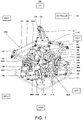
- Fig. 1 is a perspective view illustrating an outline configuration of the manipulating device according to Embodiment 1.
- Fig. 2 is a plan view of the manipulating device illustrated in Fig. 1 .
- an up-and-down direction, a front-and-rear direction, and a left-and-right direction of the manipulating device are expressed as an up-and-down direction, a front-and-rear direction, and a left-and-right direction in this figure
- the front-and-rear direction and the left-and-right direction of the manipulating device are expressed as a front-and-rear direction and a left-and-right direction in this figure.
- a manipulating device 100 includes a base part 101, a user interface 102, parallel link mechanisms 103A-103C, position sensors 104A-104F, and a controller 110, and by an operator operating the user interface 102, a position and/or a posture of a robot 200 which will be described later are controlled.
- the base part 101 is formed in a substantially rectangular shape, and the user interface 102 is disposed thereabove.
- the base part 101 and the user interface 102 are coupled through three sets of parallel link mechanisms 103A-103C so as to have six degrees of freedom.
- the user interface 102 has a movable part 11 and a grip part 12.
- the movable part 11 is comprised of a plate part to which upper ends of the parallel link mechanisms 103A-103C are connected, and a cylindrical part provided so as to stand from an upper surface of the plate part.
- the grip part 12 of a substantially cylindrical shape is provided so as to stand from an upper surface of the cylindrical part of the movable part 11.
- the grip part 12 is a portion where the operator grips, and is provided with various kinds of buttons 12A and 12B for operating the robot 200.
- the button 12A and/or the button 12B may function, for example, as a switch (a trigger, a switch) for switching a position control and a posture control of the robot 200.
- the parallel link mechanisms 103A-103C are disposed at equal angular interval (120° interval) when seen from above.
- the parallel link mechanism 103A has a pair of arm parts 14A and 14B, and a pair of link parts 15A and 15B.
- the parallel link mechanism 103B has a pair of arm parts 14C and 14D, and a pair of link parts 15C and 15D
- the parallel link mechanism 103C has a pair of arm parts 14E and 14F, and a pair of link parts 15E and 15F.
- the link part 15A is rotatably connected at an upper end part (tip-end part) with the movable part 11 of the user interface 102 through a first joint 107A. Moreover, the link part 15A is rotatably connected at a lower end (base-end part) with an outward end part 3A (tip-end part) of the arm part 14A through a second joint 108A (refer to Fig. 3 ).
- the link part 15B is rotatably connected at an upper end part (tip-end part) with the movable part 11 of the user interface 102 through a first joint 107B. Moreover, the link part 15B is rotatably connected at a lower end (base-end part) with an outward end part 3B (tip-end part) of the arm part 14B through a second joint 108B (refer to Fig. 3 ).
- first joints 107A and 107B and the second joints 108A and 108B may be used as the first joints 107A and 107B and the second joints 108A and 108B.
- link parts 15C-15F are configured similarly to the link parts 15A and 15B, the detailed description thereof is omitted.
- the pair of arm parts 14A and 14B are described in detail with reference to Fig. 3 .
- the arm part 14B is configured similarly to the arm part 14A, the detailed description thereof is omitted.
- the other pairs of arm parts 14C-14F are configured similarly to the arm part 14A, the detailed description thereof is omitted.
- Fig. 3 is a perspective view illustrating an outline configuration of the pair of arm parts of the manipulating device illustrated in Fig. 1 .
- the arm part 14A is formed in a substantially V-shape, and its bending portion 1A constitutes the base-end part of the arm part 14A. Moreover, a through-hole 2A is formed in the bending portion 1A.
- An output shaft of the driver (here, a servo motor) 106A is fixed directly or indirectly to the through-hole 2A by a suitable device (not illustrated).
- the output shaft of the driver 106A may be supported by a bearing member (for example, a bearing) provided to the supporting member 111A.
- the driver 106A may be configured to drive the user interface 102 so that the user interface 102 is not lowered from the origin by the weight of the user interface 102, etc.
- the outward end part 3A constitutes the tip-end part of the arm part 14A of the arm part 14A.
- the base-end part of the link part 15A is rotatably connected with the outward end part 3A through the second joint 108A (refer to Figs. 1 and 2 ).
- one of the arm parts 14A and 14B follows the operation of the other arm part, and when a load at the first holding force or more is applied to the first connecting member 105A, the arm part 14A and the arm part 14B operate independently.
- the first connecting member 105A may be, for example, comprised of a tensile spring. Moreover, the first connecting member 105A may be, for example, comprised of the drivers 106A and 106B. In this case, the arm part 14A and the arm part 14B are connected with each other electrically. Moreover, when the first connecting member 105A is comprised of the drivers 106A and 106B, a torque sensor etc. is provided to the output shafts of the drivers 106A and 106B, the controller 110 determines whether the load more than the first holding force is applied based on a torque value detected by the torque sensor, and controls the drivers 106A and 106B based on the determination.
- the first holding force may be set beforehand by an experiment etc.
- the first holding force may be 0.1 N ⁇ m to 1.0 N ⁇ m.
- a spring constant etc. may suitably be set so that the tensile spring has the first holding force.
- the motor is selected based on, for example, the weight of the user interface 102, and the load to be applied to the joint, such as the first joint 107A.
- the supporting member 111A is provided with the position sensor 104A which detects the position of the base-end part of the arm part 14A (here, the bending portion 1A).
- the supporting member 111B is provided with the position sensor 104B which detects the position of the base-end part of the arm part 14B (here, the bending portion 1B).
- the supporting member 111C is provided with a position sensor 104C which detects the position of the base-end part of the arm part 14C
- the supporting member 111D is provided with a position sensor 104D which detects the position of the base-end part of the arm part 14D
- the supporting member 111E is provided with a position sensor 104E which detects the position of the base-end part of the arm part 14E
- the supporting member 111F is provided with a position sensor 104F which detects the position of the base-end part of the arm part 14F.
- the position sensors 104A-104F are configured to detect the positions of the base-end parts of the arm parts 14A-14F, respectively, and output the detected positional information to the controller 110.
- the position sensors 104A-104F may be, for example, rotation sensors which detect rotational positions of the base-end parts of the arm parts 14A-14F.
- the rotation sensor may be, for example, a rotary encoder, a potentiometer, or a laser sensor.
- the position sensors 104A-104F may detect the rotational positions of the base-end parts of the arm parts 14A-14F directly or indirectly.
- the position sensors 104A-104F may detect the rotational positions of the output shafts of the drivers 106A-106F as the rotational positions of the base-end parts of the arm parts 14A-14F, respectively.
- the position sensors 104A-104F may convert the rotational motions (rotational operation) of the arm parts 14A-14F into linear motions by using mechanisms (ball-screw mechanism etc.) which convert the rotational motions into the linear motions (linear operation), and detect the displacements by linear sensors.
- the linear sensor may be, for example, a linear encoder or a laser sensor.
- the controller 110 includes an arithmetic part, such as a microprocessor or a CPU, and a memory, such as a ROM and/or a RAM (not illustrated).
- the memory stores information on a basic program, various fixed data, etc.
- the arithmetic part controls various operations of the robot 200 by reading and executing software, such as the basic program stored in the memory.
- controller 110 may be comprised of a sole controller 110 which carries out a centralized control, or may be comprised of a plurality of controllers 110 which collaboratively carry out a distributed control.
- controller 110 may be comprised of a microcomputer, or may be comprised of a MPU, a PLC (Programmable Logic Controller), or a logic circuit.
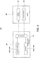
- Fig. 4 is a block diagram illustrating an outline configuration of the robot system provided with the manipulating device according to Embodiment 1.
- the grip part 12 when the grip part 12 is in the initial state (at the origin), the grip part 12 is disposed so that its axial center inclines forward. Therefore, when the operator grips the grip part 12, it can be prevented that an excessive force is applied to the operator's wrist. Therefore, the operator's fatigue can be reduced.
- a through-hole is formed in the inward end part 4A of the arm part 14A, and a base-end part of the bolt 131A, onto which the bearing member 130A is fitted, is fitted into the through-hole.
- a hypoid gear 151A is fitted onto a tip-end part of the bolt 131A.
- the hypoid gear 151A is formed in a substantially disk shape, and gear teeth are arranged in an annular shape.
- the bearing member 130A is disposed on an outer circumferential surface of the hypoid gear 151A, and rotatably supports the hypoid gear 151A.
- the arm part 14A and the arm part 14B can be operated more sensitively to the load applied to the first connecting member 105A.
- a manipulating device according to Embodiment 2 is provided, in the movable part, with a reversal preventing member configured to prevent a reversal of the link part.
- the arm part 14A is connected with the first pulley 141A through a first shaft member 161A.
- one end of the first shaft member 161A is fitted into the through-hole 2A (refer to Figs. 15 to 17 ) formed in the inward end part 4A of the arm part 14A through a suitable device, and the other end of the first shaft member 161A is fitted into the first pulley 141A through a suitable device.
- the first shaft member 161A is disposed so that a bearing member provided to an upper end of each of the supporting member 111A and the supporting member 112A is fitted therein.
- the arm part 14B is formed in a substantially T-shape, and a counter weight 9B for maintaining a weight balance with the outward end part (tip-end part) 3B is provided to the inward end part (base-end part) 4B.
- the through-hole 2B is formed at a suitable location of the inward end part 4B at a tip-end side of the counter weight 9B.
- One end of the first shaft member (not illustrated) is fitted into the through-hole 2B.
- a stop 6A is provided to an upper part of the arm part 14A at a tip-end side of the through-hole 2A.
- the stop 6A is configured to regulate a pivot range of the arm part 14B when the arm part 14A and the arm part 14B pivot independently.
- first connecting member 105A is connected with the inward end part 4B of the arm part 14B through the first fastening member 5B.
- the wire 109A is connected to the other end of the first connecting member 105A.
- the wire 109A is disposed so as to pass through between the pair of pulleys 121B and 122B provided to the outward end part (tip-end part) 3B of the arm part 14B.
- a tip-end part of the wire 109A is fixed to the outward end part 3A of the arm part 14A. That is, in Embodiment 2, the first connecting member 105A is disposed along the extending direction of the arm part 14A.
- roller parts 171B and 172B are disposed at a suitable location of the inward end part 4B of the arm part 14B at a base-end side of the pulley 121B.
- the roller parts 171B and 172B are disposed in a side surface of the arm part 14B opposing to the arm part 14A.
- a roller guide part 173A is provided to the part of the arm part 14A opposing to the roller parts 171B and 172B so as to extend in the up-and-down direction.
- stepped parts 174A and 175A may be provided to the roller guide part 173A.
- Fig. 18 is a side view illustrating an outline configuration near the movable part in the manipulating device illustrated in Fig. 13 .
- Fig. 19 is a perspective view illustrating an outline configuration near the movable part in the manipulating device illustrated in Fig. 13 . Note that, in Figs. 18 and 19 , illustration of the grip part etc. of the user interface is omitted.
- the movable part 11 is formed in a substantially disk shape, and plate-shaped protrusions 41A-41C are provided to a side surface of the movable part 11 so that they project in three directions.
- the link part 15A is rotatably connected with a central part of one side wall of the protrusion 41A through the first joint 107A.
- the link part 15B is rotatably connected to a central part of the other side wall of the protrusion 41A through the first joint 107B.
- the link parts 15C and 15D are rotatably connected with the central parts of both side walls of the protrusion 41B through the first joints 107C and 107D, respectively.
- Bar-shaped reversal preventing members 51C and 51D are provided to tip-end parts of both the side walls of the protrusion 41B.
- the link parts 15E and 15F are rotatably connected with central parts of both side walls of the protrusion 41C through the first joints 107E and 107F, respectively.
- Bar-shaped reversal preventing members 51E and 51F are provided to tip-end parts of both the side walls of the protrusion 41C.
- the reversal preventing members 51A-51F are provided to the respective link parts 15A-15F, it is not limited to this configuration.
- the reversal preventing member may be provided at least one of the link parts 15A-15F, or the reversal preventing member may not be provided to all of the link parts.
- the roller parts 171B and 172B are provided to the arm part 14B, and the roller guide part 173A on which the roller parts 171B and 172B move is provided to the arm part 14A.
- roller parts 171B and 172B move along the roller guide part 173A to prevent the arm part 14A and the arm part 14B contact and slide on each other.
- the roller parts 171B and 172B must overcome the stepped parts 174A and 175A in order for the arm part 14B to pivot independently from the arm part 14A. Therefore, the first holding force can be reduced, as compared with the case where the stepped parts 174A and 175A are not provided.
- the reversal preventing members 51A-51F are provided to the movable part 11 for the respective link parts 15A-15F.
- each link part can be prevented. Moreover, the operator can easily understand an operating range of the user interface 102 by the link part contacting the reversal preventing member. Therefore, the operator can concentrate on the operation of the robot 200, and thereby the work efficiency is improved.
- the manipulating device according to Embodiment 3 is further provided with a second connecting member which connects the arm part with the base part.
- the manipulating device 100 according to Embodiment 3 is the same in the fundamental configuration as the manipulating device 100 according to Embodiment 1, it differs in that the second connecting member which connects the arm part with the base part 101 is provided.
- the second connecting member 113A is rotatably connected at one end with the inward end part 4A of the arm part 14A through the first fastening member 5A, and the other end is rotatably connected with a suitable location of the base part 101 through a second fastening member 8A.
- the second connecting member is provided, similar to the arm parts 14A and 14B.
- the second connecting member is configured to prevent the user interface 102 from being lowered from the origin by the weight of the user interface 102, etc.
- the second connecting member may be, for example, comprised of a tensile spring.
- a spring constant etc. may suitably be set so that the user interface 102 is not lowered from the origin by the weight of the user interface 102, etc.
- the spring may be configured so as to be elastically deformed when the load more than the first holding force is applied. As configured in this way, the tensile spring can also function as the first connecting member.
- the second connecting member may be comprised of the driver.
- the controller 110 causes the driver to drive the user interface 102 so that the user interface 102 is not lowered from the origin by the weight of the user interface 102, etc.
- a torque sensor etc. may be provided to the output shaft of the driver.
- the controller 110 determines that the load less than the first holding force is applied based on a torque value detected by the torque sensor etc., it causes the driver to drive one of the pair of arm parts so as to follow the operation of the other arm part.
- the controller 110 determines that the load more than the first holding force is applied, it causes the driver to drive the pair of arm parts so as to be operated independently.
- the driver can also function as the first connecting member.
Landscapes
- Engineering & Computer Science (AREA)
- Physics & Mathematics (AREA)
- General Physics & Mathematics (AREA)
- Automation & Control Theory (AREA)
- Mechanical Engineering (AREA)
- General Engineering & Computer Science (AREA)
- Robotics (AREA)
- Manipulator (AREA)
- Transmission Devices (AREA)
- Mechanical Control Devices (AREA)
Abstract
Description
- The present disclosure relates to a manipulating device.
- Parallel manipulators capable of operating with six degrees of freedom are known (for example, refer to Patent Document 1). The parallel manipulator disclosed in
Patent Document 1 includes an end platform for supporting an object to be operated, and a middle platform disposed so as to be separated from the end platform and coupled to the end platform through a coupling element. A plurality of first links are coupled to the end platform, and a plurality of second links are coupled to the middle platform. - In the parallel manipulator disclosed in
Patent Document 1, it is described that a user can grip a handle attached to the end platform, and operates the end platform like a joystick. - [Patent Document 1]
JP2005-536703A - However, in the parallel manipulator disclosed in
Patent Document 1, the first links are coupled to the end platform and the second links are coupled to the middle platform. That is, since the first links and the second links are coupled to different platforms, there is a problem that the device becomes a large size. - The present disclosure is to solve the conventional problem, and one purpose thereof is to provide a manipulating device which can be reduced in size, as compared with the conventional manipulating device.
- In order to solve the above problem, a manipulating device according to one aspect of the present disclosure includes a base part, a user interface disposed above the base part and having a movable part and a grip part, a parallel link mechanism having a pair of arm parts and a pair of link parts, a position sensor configured to detect a position of a base-end part of the arm part, and a controller configured to control at least one of a position and a posture of a robot based on the position detected by the position sensor. The arm part is rotatably connected at a base-end part to the base part, the link part is rotatably connected at a base-end part to the arm part, and is rotatable connected at a tip-end part to the movable part, and the base part is coupled to the movable part through three sets of parallel link mechanisms with six degrees of freedom.
- Therefore, it can be reduced in the size, as compared with the conventional manipulating device.
- According to the manipulating device of the present disclosure, it can be reduced in the size, as compared with the conventional manipulating device.
-
-
Fig. 1 is a perspective view illustrating an outline configuration of a manipulating device according toEmbodiment 1. -
Fig. 2 is a plan view of the manipulating device illustrated inFig. 1 . -
Fig. 3 is a perspective view illustrating an outline configuration of a pair of arm parts of the manipulating device illustrated inFig. 1 . -
Fig. 4 is a block diagram illustrating an outline configuration of a robot system provided with the manipulating device according toEmbodiment 1. -
Fig. 5A is a schematic diagram illustrating an outline configuration of the pair of arm parts of the manipulating device illustrated inFig. 1 . -
Fig. 5B is a schematic diagram illustrating the outline configuration of the pair of arm parts of the manipulating device illustrated inFig. 1 . -
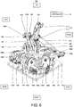
Fig. 6 is a perspective view illustrating an outline configuration of a manipulating device of Modification 2 inEmbodiment 1. -
Fig. 7 is a perspective view illustrating an outline configuration of a substantial part of a parallel link mechanism in the manipulating device illustrated inFig. 6 . -
Fig. 8 is a perspective view illustrating an outline configuration of a manipulating device of Modification 3 inEmbodiment 1. -
Fig. 9 is a perspective view illustrating an outline configuration of a substantial part of a parallel link mechanism in the manipulating device illustrated inFig. 8 . -
Fig. 10 is a plan view illustrating the outline configuration of the substantial part of the parallel link mechanism in the manipulating device illustrated inFig. 8 . -
Fig. 11 is a side view illustrating the outline configuration of the substantial part of the parallel link mechanism in the manipulating device illustrated inFig. 8 . -
Fig. 12 is a schematic diagram illustrating an outline configuration of the substantial part of the parallel link mechanism in the manipulating device illustrated inFig. 8 . -
Fig. 13 is a perspective view illustrating an outline configuration of a manipulating device according to Embodiment 2. -
Fig. 14 is a side view of the manipulating device illustrated inFig. 13 . -
Fig. 15 is a perspective view illustrating an outline configuration of a substantial part of a parallel link mechanism in the manipulating device illustrated inFig. 13 . -
Fig. 16 is a perspective view illustrating an outline configuration of the substantial part of the parallel link mechanism in the manipulating device illustrated inFig. 13 . -
Fig. 17 is a side view illustrating an outline configuration of the substantial part of the parallel link mechanism in the manipulating device illustrated inFig. 13 . -
Fig. 18 is a side view illustrating an outline configuration near a movable part in the manipulating device illustrated inFig. 13 . -
Fig. 19 is a perspective view illustrating the outline configuration near the movable part in the manipulating device illustrated inFig. 13 . -
Fig. 20 is a schematic diagram illustrating an outline configuration of a substantial part of a manipulating device according to Embodiment 3. - Hereinafter, embodiments of the present disclosure will be described with reference to the drawings. Note that, throughout the drawings, the same or corresponding parts are denoted with the same reference characters to omit redundant description. Moreover, throughout the drawings, components for explaining the present disclosure are selectively illustrated, and illustration of other components may be omitted. Further, the present disclosure is not limited to the following embodiments.
- A manipulating device according to
Embodiment 1 includes a base part, a user interface disposed above the base part and having a movable part and a grip part, a parallel link mechanism having a pair of arm parts and a pair of link parts, a position sensor which detects the position of a base-end part of the arm part, and a controller which controls a position and/or a posture of the robot based on the position detected by the position sensor. The arm part is rotatably connected at a base-end part to the base part, and the link part is rotatably connected at a base-end part to the arm part, and is rotatably connected at a tip-end part to the movable part. The base part is coupled to the movable part through three sets of parallel link mechanisms so as to have six degrees of freedom. - Moreover, in the manipulating device according to
Embodiment 1, the pair of arm parts may be connected with each other through a first connecting member having a given first holding force set beforehand. - Moreover, in the manipulating device according to
Embodiment 1, when an operator operates the user interface to apply a load less than the first holding force to the first connecting member, one of the pair of arm parts operates so as to follow the operation of the other arm part, and when a load at the first holding force or more is applied to the first connecting member, the pair of arm parts operate independently. - Hereinafter, one example of the manipulating device according to
Embodiment 1 is described with reference toFigs. 1 to 5B . -
Fig. 1 is a perspective view illustrating an outline configuration of the manipulating device according toEmbodiment 1.Fig. 2 is a plan view of the manipulating device illustrated inFig. 1 . Note that, inFig. 1 , an up-and-down direction, a front-and-rear direction, and a left-and-right direction of the manipulating device are expressed as an up-and-down direction, a front-and-rear direction, and a left-and-right direction in this figure, and inFig. 2 , the front-and-rear direction and the left-and-right direction of the manipulating device are expressed as a front-and-rear direction and a left-and-right direction in this figure. - As illustrated in
Figs. 1 and2 , a manipulatingdevice 100 according toEmbodiment 1 includes abase part 101, auser interface 102,parallel link mechanisms 103A-103C,position sensors 104A-104F, and acontroller 110, and by an operator operating theuser interface 102, a position and/or a posture of arobot 200 which will be described later are controlled. - The
base part 101 is formed in a substantially rectangular shape, and theuser interface 102 is disposed thereabove. Thebase part 101 and theuser interface 102 are coupled through three sets ofparallel link mechanisms 103A-103C so as to have six degrees of freedom. - The
user interface 102 has amovable part 11 and agrip part 12. Themovable part 11 is comprised of a plate part to which upper ends of theparallel link mechanisms 103A-103C are connected, and a cylindrical part provided so as to stand from an upper surface of the plate part. Thegrip part 12 of a substantially cylindrical shape is provided so as to stand from an upper surface of the cylindrical part of themovable part 11. Thegrip part 12 is a portion where the operator grips, and is provided with various kinds ofbuttons robot 200. Thebutton 12A and/or thebutton 12B may function, for example, as a switch (a trigger, a switch) for switching a position control and a posture control of therobot 200. - Note that, in
Embodiment 1, thegrip part 12 is disposed, in an initial state (at an origin), so that its axial center inclines forward. Therefore, when the operator grips thegrip part 12, it can be prevented that an excessive force is applied to the operator's wrist. - The
parallel link mechanisms 103A-103C are disposed at equal angular interval (120° interval) when seen from above. Theparallel link mechanism 103A has a pair ofarm parts link parts parallel link mechanism 103B has a pair ofarm parts link parts parallel link mechanism 103C has a pair ofarm parts link parts - The
link part 15A is rotatably connected at an upper end part (tip-end part) with themovable part 11 of theuser interface 102 through a first joint 107A. Moreover, thelink part 15A is rotatably connected at a lower end (base-end part) with anoutward end part 3A (tip-end part) of thearm part 14A through a second joint 108A (refer toFig. 3 ). - Similarly, the
link part 15B is rotatably connected at an upper end part (tip-end part) with themovable part 11 of theuser interface 102 through a first joint 107B. Moreover, thelink part 15B is rotatably connected at a lower end (base-end part) with anoutward end part 3B (tip-end part) of thearm part 14B through a second joint 108B (refer toFig. 3 ). - Various kinds of joint, such as a universal joint or a ball joint, may be used as the
first joints second joints - Note that, since, the
link parts 15C-15F are configured similarly to thelink parts - The
arm part 14A is rotatably connected at a base-end part with thebase part 101 through a substantially L-shaped supportingmember 111A by a suitable device. Moreover, thearm part 14B is rotatably connected at a base-end part with thebase part 101 through a substantially L-shaped supportingmember 111B by a suitable device. Similarly, thearm parts 14C-14F are rotatably connected at base-end parts with thebase part 101 through substantially L-shaped supportingmembers 111C-111F by suitable device, respectively. - Here, the pair of
arm parts Fig. 3 . Note that, since thearm part 14B is configured similarly to thearm part 14A, the detailed description thereof is omitted. Moreover, since the other pairs ofarm parts 14C-14F are configured similarly to thearm part 14A, the detailed description thereof is omitted. -
Fig. 3 is a perspective view illustrating an outline configuration of the pair of arm parts of the manipulating device illustrated inFig. 1 . - As illustrated in
Fig. 3 , thearm part 14A is formed in a substantially V-shape, and itsbending portion 1A constitutes the base-end part of thearm part 14A. Moreover, a through-hole 2A is formed in the bendingportion 1A. An output shaft of the driver (here, a servo motor) 106A is fixed directly or indirectly to the through-hole 2A by a suitable device (not illustrated). - Note that, the output shaft of the
driver 106A may be supported by a bearing member (for example, a bearing) provided to the supportingmember 111A. Moreover, thedriver 106A may be configured to drive theuser interface 102 so that theuser interface 102 is not lowered from the origin by the weight of theuser interface 102, etc. - Moreover, the
outward end part 3A constitutes the tip-end part of thearm part 14A of thearm part 14A. As described above, the base-end part of thelink part 15A is rotatably connected with theoutward end part 3A through the second joint 108A (refer toFigs. 1 and2 ). - Further, one end of the first connecting
member 105A is rotatably connected with theinward end part 4A of thearm part 14A through thefirst fastening member 5A. The other end of the first connectingmember 105A is rotatably connected with theinward end part 4B of thearm part 14B through thefirst fastening member 5B. In more detail, when theuser interface 102 is at the origin, the first connectingmember 105A is configured to connect thearm part 14A with thearm part 14B so that the first connectingmember 105A becomes perpendicular to the extending direction of thearm part 14A. Note that, here, thefirst fastening member 5A and thefirst fastening member 5B are comprised of a bolt and a nut. - When a load less than a given first holding force set beforehand is applied to the first connecting
member 105A, one of thearm parts member 105A, thearm part 14A and thearm part 14B operate independently. - The first connecting
member 105A may be, for example, comprised of a tensile spring. Moreover, the first connectingmember 105A may be, for example, comprised of thedrivers arm part 14A and thearm part 14B are connected with each other electrically. Moreover, when the first connectingmember 105A is comprised of thedrivers drivers controller 110 determines whether the load more than the first holding force is applied based on a torque value detected by the torque sensor, and controls thedrivers - Moreover, the first holding force may be set beforehand by an experiment etc. In detail, the first holding force may be 0.1 N·m to 1.0 N·m. Moreover, when the first connecting
member 105A is comprised of a tensile spring, a spring constant etc. may suitably be set so that the tensile spring has the first holding force. Moreover, when the first connectingmember 105A is comprised of thedrivers user interface 102, and the load to be applied to the joint, such as the first joint 107A. - Moreover, as illustrated in
Figs. 1 and2 , the supportingmember 111A is provided with theposition sensor 104A which detects the position of the base-end part of thearm part 14A (here, the bendingportion 1A). Moreover, the supportingmember 111B is provided with theposition sensor 104B which detects the position of the base-end part of thearm part 14B (here, the bendingportion 1B). - Similarly, the supporting
member 111C is provided with aposition sensor 104C which detects the position of the base-end part of thearm part 14C, and the supportingmember 111D is provided with aposition sensor 104D which detects the position of the base-end part of thearm part 14D. Moreover, the supportingmember 111E is provided with aposition sensor 104E which detects the position of the base-end part of thearm part 14E, and the supportingmember 111F is provided with aposition sensor 104F which detects the position of the base-end part of thearm part 14F. - The
position sensors 104A-104F are configured to detect the positions of the base-end parts of thearm parts 14A-14F, respectively, and output the detected positional information to thecontroller 110. Theposition sensors 104A-104F may be, for example, rotation sensors which detect rotational positions of the base-end parts of thearm parts 14A-14F. The rotation sensor may be, for example, a rotary encoder, a potentiometer, or a laser sensor. Note that theposition sensors 104A-104F may detect the rotational positions of the base-end parts of thearm parts 14A-14F directly or indirectly. For example, theposition sensors 104A-104F may detect the rotational positions of the output shafts of thedrivers 106A-106F as the rotational positions of the base-end parts of thearm parts 14A-14F, respectively. - Alternatively, for example, the
position sensors 104A-104F may convert the rotational motions (rotational operation) of thearm parts 14A-14F into linear motions by using mechanisms (ball-screw mechanism etc.) which convert the rotational motions into the linear motions (linear operation), and detect the displacements by linear sensors. The linear sensor may be, for example, a linear encoder or a laser sensor. - The
controller 110 includes an arithmetic part, such as a microprocessor or a CPU, and a memory, such as a ROM and/or a RAM (not illustrated). The memory stores information on a basic program, various fixed data, etc. The arithmetic part controls various operations of therobot 200 by reading and executing software, such as the basic program stored in the memory. - Note that the
controller 110 may be comprised of asole controller 110 which carries out a centralized control, or may be comprised of a plurality ofcontrollers 110 which collaboratively carry out a distributed control. Moreover, thecontroller 110 may be comprised of a microcomputer, or may be comprised of a MPU, a PLC (Programmable Logic Controller), or a logic circuit. - Next, one example of a robot system provided with the manipulating device according to
Embodiment 1 is described with reference toFig. 4 . -
Fig. 4 is a block diagram illustrating an outline configuration of the robot system provided with the manipulating device according toEmbodiment 1. - As illustrated in
Fig. 4 , therobot system 300 provided with the manipulating device according toEmbodiment 1 includes the manipulatingdevice 100 and therobot 200. Therobot 200 may be a horizontal articulated dual-arm robot, or may be other robots of a horizontal articulated or vertical articulated type. - The
robot 200 has thedriver 201 which relatively drives each joint. Thedriver 201 is configured to drive based on the instruction values of the position and/or the posture of therobot 200 outputted from thecontroller 110. Thedriver 201 may be, for example, a servo motor. - Moreover, the
robot 200 may have aforce sensor 202. Theforce sensor 202 is configured to detect a reaction force which acts on an end effector etc. from the outside, or a force acted by the end effector to the outside, and output the detected force information to thecontroller 110. Thecontroller 110 may perform a haptics control which feeds back the force information detected by theforce sensors 202 to thedrivers 106A-106F. Moreover, thecontroller 110 may bilaterally control the manipulatingdevice 100 and therobot 200. - Next, operation and effects of the manipulating device according to
Embodiment 1 are described with reference toFigs. 1 to 5B . -
Figs. 5A and 5B are schematic diagrams illustrating an outline configuration of the pair of arm parts of the manipulating device illustrated inFig. 1 , whereFig. 5A illustrates a state where the load less than the first holding force is applied to the first connecting member, andFig. 5B illustrates a state where the load at the first holding force or more is applied to the first connecting member. - When the operator grips the
grip part 12 of theuser interface 102 and operates theuser interface 102, themovable part 11 moves in the up-and-down, front-and-rear, and left-and-right directions. In connection with this, thelink parts 15A-15F and thearm parts 14A-14F rotate (pivot). - At this time, as illustrated in
Fig. 5A , if the load less than the first holding force is applied to the first connectingmember 105A, one of thearm parts member 105A. - Similarly, if the load less than the first holding force is applied to the first connecting
member 105B, one of thearm parts member 105B. Moreover, if the load less than the first holding force is applied to the first connectingmember 105C, one of thearm parts member 105C. - Therefore, the
movable part 11 of theuser interface 102 moves in the up-and-down, front-and-rear, and left-and-right directions, while maintaining the horizontal state. Therefore, a control instruction value outputted from thecontroller 110 becomes an instruction value for changing the positional information of therobot 200, and thereby therobot 200 can maintain the posture state just before the operator operates theuser interface 102. That is, when the operator operates theuser interface 102 so that the load less than the first holding force is applied to the first connectingmembers 105A-105C (so that themovable part 11 maintains the horizontal state), the position of therobot 200 can be changed. - On the other hand, as illustrated in
Fig. 5B , if the load at the first holding force or more is applied to the first connectingmember 105A, thearm parts member 105B, thearm parts member 105C, thearm parts - Thus, the
movable part 11 of theuser interface 102 inclines in any direction and moves in the up-and-down, front-and-rear, and left-and-right directions, while being inclined. Therefore, the control instruction value outputted from thecontroller 110 becomes the posture information of therobot 200, or the posture information and the positional information of therobot 200, and the posture of therobot 200, or the posture and the position of therobot 200 can be changed. That is, when the operator operates theuser interface 102 so that the load more than the first holding force is applied to at least one or more first connecting members among the first connectingmembers 105A-105C, therobot 200 can be operated so that the position of therobot 200, or the position and the posture of therobot 200 are changed. - In the manipulating
device 100 according toEmbodiment 1 configured in this way, each of thelink parts 15A-15F which constitute theparallel link mechanisms 103A-103C is rotatably coupled to onemovable part 11. Therefore, the size can be reduced, as compared with the parallel manipulator disclosed inPatent Document 1. - Moreover, in the manipulating
device 100 according toEmbodiment 1, when thegrip part 12 is in the initial state (at the origin), thegrip part 12 is disposed so that its axial center inclines forward. Therefore, when the operator grips thegrip part 12, it can be prevented that an excessive force is applied to the operator's wrist. Therefore, the operator's fatigue can be reduced. - Moreover, in the manipulating
device 100 according toEmbodiment 1, the first connecting member is disposed at the pair of arm parts. - Therefore, when the operator operates the
user interface 102 so that the load less than the first holding force is applied to the first connectingmembers 105A-105C, therobot 200 can be operated so that the position of therobot 200 is changed. - On the other hand, when the operator operates the
user interface 102 so that the load more than the first holding force is applied to at least one or more first connecting members among the first connectingmembers 105A-105C, therobot 200 can be operated so that the position of therobot 200, or the position and the posture of therobot 200 are changed. - That is, when the operator changes the load applied to the first connecting member, the position control and the posture control of the
robot 200 can be switched. - Note that, although in the manipulating
device 100 according toEmbodiment 1 thedrivers 106A-106F are provided, it is not limited to this configuration. One or more of thedrivers 106A-106F may not be provided. - Next, a modification of the manipulating
device 100 according toEmbodiment 1 is described. - A manipulating device of the
modification 1 ofEmbodiment 1 further includes a driver which is provided to the base-end part of the arm part and drives the arm part, and when performing the position control of the robot, the controller causes the driver to drive one of the pair of arm parts so as to follow the operation of the other arm part. - Moreover, the manipulating device of
Modification 1 may further include a switch which switches between the position control and the posture control of the robot. - Below, one example of the manipulating device of
Modification 1 is described. - Since the manipulating
device 100 according toModification 1 has a similar configuration to the manipulatingdevice 100 ofEmbodiment 1, the detailed description thereof is omitted. - Note that, in
Modification 1, thebutton 12A and/or thebutton 12B function as the switch for switching between the position control and the posture control of therobot 200. In detail, for example, when the operator operates (presses) thebutton 12A, the position control of therobot 200 is executed, and when the operator operates (presses) thebutton 12B, the posture control of the robot 200 (including both the posture control and the position control) is executed. - Moreover, in the manipulating
device 100 ofModification 1, at least one or more first connecting members among the first connectingmembers 105A-105C may not be provided. - When the operator operates (presses) the
button 12A and operates theuser interface 102 in order to execute the position control of therobot 200, thecontroller 110 controls the driver which drives one of the pair of arm parts to follow the operation (pivoting) of the other arm part. In detail, thecontroller 110 acquires the positional information on the base-end part of the other arm part (for example, a rotational angle) from the position sensor, and controls the driver which drives one arm part based on the positional information. - On the other hand, when the operator operates (presses) the
button 12B and operates theuser interface 102 in order to execute the posture control of therobot 200, thecontroller 110 controls the driver so that the pair of arm parts operate (pivot) independently. At this time, thecontroller 110 may control the driver so that the operator does not feel the load. Moreover, thecontroller 110 may execute the haptics control which feeds back the force information detected by theforce sensor 202 to thedrivers 106A-106F. Alternatively, thecontroller 110 may bilaterally control the manipulatingdevice 100 and therobot 200. - Even by the manipulating
device 100 ofModification 1 configured in this way, similar operation and effects to the manipulatingdevice 100 according toEmbodiment 1 can be obtained. - Moreover, in the manipulating
device 100 ofModification 1, since the position control and the posture control of therobot 200 can be switched by using thebutton 12A and thebutton 12B, therobot 200 can be operated easily. - Note that, in
Modification 1, although the switching between the position control and the posture control of therobot 200 is performed by using thebutton 12A and thebutton 12B is adopted, it is not limited to this configuration. The switching between the position control and the posture control of therobot 200 may be performed by using thebutton 12A, or may be performed by using thebutton 12B. In this case, the position control and the posture control of therobot 200 may be switched by pressing the button once and pressing twice. -
Fig. 6 is a perspective view illustrating an outline configuration of a manipulating device of Modification 2 inEmbodiment 1.Fig. 7 is a perspective view illustrating an outline configuration of a substantial part of a parallel link mechanism in the manipulating device illustrated inFig. 6 . - Note that, in
Fig. 6 , the up-and-down direction, the front-and-rear direction, and the left-and-right direction of the manipulating device are expressed as an up-and-down direction, a front-and-rear direction, and a left-and-right direction in this figure, and inFig. 7 , the up-and-down direction of the manipulating device is expressed as an up-and-down direction in this figure. - As illustrated in
Fig. 6 , although the manipulatingdevice 100 of Modification 2 inEmbodiment 1 is the same in the fundamental configuration as the manipulatingdevice 100 according toEmbodiment 1, it differs in that the rotation shaft of the base-end part of the arm part which constitutes the parallel link mechanism and the output shaft of the driver are coupled through a belt drive, and the first connecting member is provided to the tip-end part of the arm part. - Below, a configuration of the
parallel link mechanism 103A is described with reference toFig. 7 . Note that, since theparallel link mechanisms parallel link mechanism 103A, the detailed description thereof is omitted. Moreover, since thearm part 14B is configured similarly to thearm part 14A, the detailed description thereof is omitted. - As illustrated in
Fig. 7 , thearm part 14A is formed in a bar shape, and one end of the first connectingmember 105A is connected with theoutward end part 3A (tip-end part) through thefirst fastening member 5A. The other end of the first connectingmember 105A is rotatably connected with the outward end part (tip-end part) 3B of thearm part 14B through thefirst fastening member 5B. In more detail, when theuser interface 102 is at the origin, the first connectingmember 105A is configured to connect thearm part 14A and thearm part 14B so as to become perpendicular to the extending direction of thearm part 14A. - The inward end part (base-end part) 4A of the
arm part 14A is rotatably connected with an upper end part of the plate-shaped supportingmember 111A through the bearingmember 130A. In detail, a through-hole is formed in theinward end part 4A, and a base-end part of thebolt 131A, onto which the bearingmember 130A is fitted, is fitted into the through-hole. - Moreover, a
first pulley 141A is fitted onto an intermediate location of thebolt 131A, and a tip-end part thebolt 131A is rotatably provided to an upper end part of the supportingmember 112A through the bearingmember 132A. That is, thebolt 131A constitutes a rotation shaft of the base-end part of thearm part 14A, and in connection with the rotation of thearm part 14A, thearm part 14A is connected with thefirst pulley 141A so that thefirst pulley 141A rotates. - Note that the supporting
member 111A and the supportingmember 112A are provided so as to stand from an upper surface of abase plate 120A disposed on an upper surface of thebase part 101. - The
first pulley 141A is disposed so as to be sandwiched between the supportingmember 111A and the supportingmember 112A. Moreover, below thefirst pulley 141A, a second pulley (not illustrated) with a smaller radius than that of thefirst pulley 141A is disposed. The second pulley is connected with the output shaft of thedriver 106A through a suitable device (for example, a bearing etc.). Moreover, abelt 143A is wound around outer circumferential surfaces of thefirst pulley 141A and the second pulley. - Therefore, the rotational operation of the
arm part 14A is transmitted to the output shaft of thedriver 106A by abelt drive 140A comprised of thefirst pulley 141A, thebelt 143A, and the second pulley. - Even by the manipulating
device 100 of this modification 2 configured in this way, similar operation and effects to the manipulatingdevice 100 according toEmbodiment 1 can be obtained. -
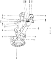
Fig. 8 is a perspective view illustrating an outline configuration of a manipulating device of Modification 3 inEmbodiment 1.Fig. 9 is a perspective view illustrating an outline configuration of a substantial part of a parallel link mechanism in the manipulating device illustrated inFig. 8 .Fig. 10 is a plan view illustrating an outline configuration of the substantial part of the parallel link mechanism in the manipulating device illustrated inFig. 8 .Fig. 11 is a side view illustrating an outline configuration of the substantial part of the parallel link mechanism in the manipulating device illustrated inFig. 8 .Fig. 12 is a schematic diagram illustrating an outline configuration of the substantial part of the parallel link mechanism in the manipulating device illustrated inFig. 8 . - Note that, in
Fig. 8 , the up-and-down direction, the front-and-rear direction, and the left-and-right direction of the manipulating device are expressed as an up-and-down direction, a front-and-rear direction, and a left-and-right direction in this figure, and inFigs. 9 ,11 , and12 , the up-and-down direction of the manipulating device is expressed as an up-and-down direction in these figures. - As illustrated in
Figs. 8 to 12 , although a manipulatingdevice 100 of Modification 3 inEmbodiment 1 is the same in the fundamental configuration as the manipulatingdevice 100 according toEmbodiment 1, it differs in that the rotation shaft of the base-end part of the arm part which constitutes the parallel link mechanism is connected with the output shaft of the driver through the hypoid gear and the belt drive, and the first connecting member is disposed in the extending direction of the arm part. - Below, a configuration of the
parallel link mechanism 103A is described with reference toFigs. 9 to 12 . Note that, since theparallel link mechanisms parallel link mechanism 103A, the detailed description thereof is omitted. - As illustrated in
Figs. 9 to 12 , thearm part 14A is formed in a bar shape, and the inward end part (base-end part) 4A is rotatably connected with the upper end part of the substantially L-shaped supportingmember 111A through the bearingmember 130A. Similarly, thearm part 14B is formed in a bar shape, and the inward end part (base-end part) 4B is rotatably connected with the upper end of the substantially L-shaped supportingmember 111B through the bearingmember 130B. - Here, a connecting state of the
inward end part 4A of thearm part 14A and theoutput shaft 26A of thedriver 106A is described in detail with reference toFig. 12 . - A through-hole is formed in the
inward end part 4A of thearm part 14A, and a base-end part of thebolt 131A, onto which the bearingmember 130A is fitted, is fitted into the through-hole. Moreover, ahypoid gear 151A is fitted onto a tip-end part of thebolt 131A. Thehypoid gear 151A is formed in a substantially disk shape, and gear teeth are arranged in an annular shape. The bearingmember 130A is disposed on an outer circumferential surface of thehypoid gear 151A, and rotatably supports thehypoid gear 151A. - Moreover, a
hypoid pinion 152A is meshed with thehypoid gear 151A. Thehypoid pinion 152A is rotatably supported at its axial part by a bearingmember 132A, and fitted at its base-end part into thefirst pulley 141A. Asecond pulley 142A is disposed outward of thefirst pulley 141A. - The
output shaft 26A of thedriver 106A is connected with thesecond pulley 142A through a suitable device (for example, a bearing etc.). Moreover, thebelt 143A is wound around the outer circumferential surface of thefirst pulley 141A and the second pulley. Therefore, the rotational operation of thearm part 14A is transmitted to theoutput shaft 26A of thedriver 106A. - The
driver 106A has acasing 36A, adriver body 16A, and anoutput shaft 26A, and thedriver body 16A and theoutput shaft 26A are disposed inside thecasing 36A. Thedriver body 16A may be, for example, a rotor and a stator of a servo motor. - Moreover, the
position sensor 104A is disposed inside thecasing 36A, and theposition sensor 104A detects a rotational position of theoutput shaft 26A of thedriver 106A and outputs the detected rotational position information to thecontroller 110. - Note that, since the connecting state of the
inward end part 4B of thearm part 14B with the output shaft of thedriver 106B is configured similarly to that of theinward end part 4A of thearm part 14A with theoutput shaft 26A of thedriver 106A, the detailed description thereof is omitted. - Moreover, as illustrated in
Figs. 10 and11 , astop 6A is provided to an upper part of theinward end part 4A of thearm part 14A. Thestop 6A is configured to regulate a pivot range of thearm part 14B when thearm part 14A and thearm part 14B pivot independently. - Moreover, one end of the first connecting
member 105A is connected with thebase end 7B of thearm part 14B through thefirst fastening member 5B. The other end of the first connectingmember 105A is connected to awire 109A. Thewire 109A is disposed so as to pass through between a pair ofpulleys arm part 14B. Moreover, the tip-end part of thewire 109A is fixed to theoutward end part 3A of thearm part 14A. That is, in Modification 3, the first connectingmember 105A is disposed along the extending direction of thearm part 14A. - Therefore, when the load less than the first holding force is applied to the first connecting
member 105A, one of thearm part 14A and thearm part 14B operates (pivots) so as to follow the operation (pivoting) of the other arm part. Moreover, when the load more than the first holding force is applied to the first connectingmember 105A, thearm part 14A and thearm part 14B operate (pivot) independently from each other. - Even by the manipulating
device 100 of Modification 3 configured in this way, similar operation and effects to the manipulatingdevice 100 according toEmbodiment 1 can be obtained. - Moreover, in the manipulating
device 100 of Modification 3, the first connectingmember 105A is disposed along the extending direction of thearm part 14A. Therefore, compared with the manipulatingdevice 100 according toEmbodiment 1 in which the first connectingmember 105A is disposed so as to bridge between thearm part 14A and thearm part 14B, a distance between thearm part 14A and thearm part 14B can be reduced, thereby reducing the size of the manipulatingdevice 100. - Further, in the manipulating
device 100 of Modification 3, when thearm part 14A and thearm part 14B operate (pivot) independently, their displacement (angular difference) is converted into a linear amount of change through thepulleys device 100 of Modification 3, the first connectingmember 105A is disposed so that the extending and contracting direction of the first connectingmember 105A become in agreement with the linear direction converted by thepulleys member 105A). - Therefore, when operating the
arm part 14A and thearm part 14B independently, thearm part 14A and thearm part 14B can be operated more sensitively to the load applied to the first connectingmember 105A. - In the manipulating device according to Embodiment 1 (including modifications), a manipulating device according to Embodiment 2 is provided, in the movable part, with a reversal preventing member configured to prevent a reversal of the link part.
- Moreover, in the manipulating device according to Embodiment 2, one of the pair of arm parts may be provided with a roller part, and the other arm part may be provided with a roller guide part on which the roller part moves.
- Below, one example of the manipulating device according to Embodiment 2 is described with reference to
Figs. 13 to 19 . -
Fig. 13 is a perspective view illustrating an outline configuration of the manipulating device according to Embodiment 2.Fig. 14 is a side view of the manipulating device illustrated inFig. 13 . Moreover,Fig. 15 is a perspective view illustrating an outline configuration of a substantial part of the parallel link mechanism in the manipulating device illustrated inFig. 13 .Fig. 16 is a perspective view illustrating an outline configuration of the substantial part of the parallel link mechanism in the manipulating device illustrated inFig. 13 .Fig. 17 is a side view illustrating an outline configuration of the substantial part of the parallel link mechanism in the manipulating device illustrated inFig. 13 . - Note that, in
Fig. 13 , the up-and-down direction, the front-and-rear direction, and the left-and-right direction of the manipulating device are expressed as an up-and-down direction, a front-and-rear direction, and a left-and-right direction in this figure, and inFig. 14 , the up-and-down direction and the front-and-rear direction of the manipulating device are expressed as an up-and-down direction and a front-and-rear direction in this figure. Moreover, inFig. 17 , illustration of a part of the arm part closer to the viewer is omitted. - As illustrated in
Figs. 13 and14 , although the manipulatingdevice 100 according to Embodiment 2 is the same in the fundamental configuration as the manipulatingdevice 100 according toEmbodiment 1, it differs in that the reversal preventing member is provided to themovable part 11, and the rotation shaft of the base-end part of the arm part which constitutes the parallel link mechanism is connected with the output shaft of the driver through the belt drive. - Moreover, as illustrated in
Figs. 15 to 17 , in the manipulatingdevice 100 according to Embodiment 2, the first connecting member is disposed in the extending direction of the arm part, one of the pair of arm parts is provided with a roller part, and the other arm part is provided with a roller guide part on which a roller part moves. - Below, a configuration of the
parallel link mechanism 103A is described with reference toFigs. 13 to 17 . Note that, since theparallel link mechanisms parallel link mechanism 103A, the detailed description thereof is omitted. - As illustrated in
Figs. 13 and14 , similar to Modification 2 ofEmbodiment 1, the rotation shaft of the inward end part (base-end part) 4A of thearm part 14A is connected with the output shaft of thedriver 106A through thebelt drive 140A. Note that, although in Modification 2 ofEmbodiment 1 thearm part 14A and thebelt drive 140A are disposed so as to be sandwiched between the supportingmember 111A and the supportingmember 112A, Embodiment 2 differs from Modification 2 ofEmbodiment 1 in that thearm part 14A and thebelt drive 140A are disposed so as to sandwich the supportingmember 111A and the supportingmember 112A. - The
arm part 14A is connected with thefirst pulley 141A through afirst shaft member 161A. In detail, one end of thefirst shaft member 161A is fitted into the through-hole 2A (refer toFigs. 15 to 17 ) formed in theinward end part 4A of thearm part 14A through a suitable device, and the other end of thefirst shaft member 161A is fitted into thefirst pulley 141A through a suitable device. Moreover, thefirst shaft member 161A is disposed so that a bearing member provided to an upper end of each of the supportingmember 111A and the supportingmember 112A is fitted therein. - Thus, the
first pulley 141A can be rotated in connection with the rotation of thearm part 14A. That is, thefirst shaft member 161A constitutes the rotation shaft of thearm part 14A. - Moreover, below the
first pulley 141A, thesecond pulley 142A with a smaller radius than thefirst pulley 141A is disposed. The output shaft of thedriver 106A is connected with thesecond pulley 142A through thesecond shaft member 162A. Moreover, thebelt 143A is wound around the outer circumferential surface of thefirst pulley 141A and thesecond pulley 142A. - Therefore, the rotational operation of the
arm part 14A is transmitted to the output shaft of thedriver 106A by thebelt drive 140A comprised of thefirst pulley 141A, thebelt 143A, and the second pulley. - Next, a configuration of the pair of
arm parts parallel link mechanism 103A is described with reference toFigs. 15 to 17 . Note that, since the pair ofarm parts parallel link mechanism 103B and the pair ofarm parts parallel link mechanism 103C are configured similarly to the pair ofarm parts - As illustrated in
Figs. 15 to 17 , thearm part 14A is formed in a substantially T-shape, and acounter weight 9A for maintaining a weight balance with theoutward end part 3A (tip-end part) is provided to the inward end part (base-end part) 4A. The through-hole 2A is formed at a suitable location of theinward end part 4A at a tip-end side of thecounter weight 9A. As described above, one end of thefirst shaft member 161A (not illustrated inFigs. 15 to 17 ) is fitted into the through-hole 2A. - Similarly, the
arm part 14B is formed in a substantially T-shape, and acounter weight 9B for maintaining a weight balance with the outward end part (tip-end part) 3B is provided to the inward end part (base-end part) 4B. The through-hole 2B is formed at a suitable location of theinward end part 4B at a tip-end side of thecounter weight 9B. One end of the first shaft member (not illustrated) is fitted into the through-hole 2B. - Moreover, as illustrated in
Figs. 15 to 17 , astop 6A is provided to an upper part of thearm part 14A at a tip-end side of the through-hole 2A. Thestop 6A is configured to regulate a pivot range of thearm part 14B when thearm part 14A and thearm part 14B pivot independently. - On the other hand, one end of the first connecting
member 105A is connected with theinward end part 4B of thearm part 14B through thefirst fastening member 5B. Thewire 109A is connected to the other end of the first connectingmember 105A. Thewire 109A is disposed so as to pass through between the pair ofpulleys arm part 14B. Moreover, a tip-end part of thewire 109A is fixed to theoutward end part 3A of thearm part 14A. That is, in Embodiment 2, the first connectingmember 105A is disposed along the extending direction of thearm part 14A. - Moreover, the
roller parts inward end part 4B of thearm part 14B at a base-end side of thepulley 121B. In more detail, theroller parts arm part 14B opposing to thearm part 14A. On the other hand, aroller guide part 173A is provided to the part of thearm part 14A opposing to theroller parts parts roller guide part 173A. - Next, a configuration of the reversal preventing member is described with reference to
Figs. 18 and 19 . -
Fig. 18 is a side view illustrating an outline configuration near the movable part in the manipulating device illustrated inFig. 13 .Fig. 19 is a perspective view illustrating an outline configuration near the movable part in the manipulating device illustrated inFig. 13 . Note that, inFigs. 18 and 19 , illustration of the grip part etc. of the user interface is omitted. - As illustrated in
Figs. 18 and 19 , themovable part 11 is formed in a substantially disk shape, and plate-shapedprotrusions 41A-41C are provided to a side surface of themovable part 11 so that they project in three directions. - The
link part 15A is rotatably connected with a central part of one side wall of theprotrusion 41A through the first joint 107A. Moreover, thelink part 15B is rotatably connected to a central part of the other side wall of theprotrusion 41A through the first joint 107B. - The bar-shaped
reversal preventing member 51A is provided to a tip-end part of one side wall of theprotrusion 41A, and a bar-shapedreversal preventing member 51B is provided to a tip-end part of the other side wall of theprotrusion 41A. - The
reversal preventing member 51A is configured to prevent a reversal of thelink part 15A by contacting thelink part 15A. Similarly, thereversal preventing member 51B is configured to prevent a reversal of thelink part 15B by contacting thelink part 15B. - Here, the "reversal of the link part" refers to that, as the link part rotates, an angle formed by this link part and the
movable part 11 becomes larger than 180°. Note that, when thegrip part 12 is in the initial state (at the origin), suppose that the angle formed by the link part and themovable part 11 is less than 180°. - Similarly, the
link parts protrusion 41B through thefirst joints reversal preventing members protrusion 41B. Moreover, thelink parts protrusion 41C through thefirst joints reversal preventing members protrusion 41C. - Note that, in Embodiment 2, although the
reversal preventing members 51A-51F are provided to therespective link parts 15A-15F, it is not limited to this configuration. The reversal preventing member may be provided at least one of thelink parts 15A-15F, or the reversal preventing member may not be provided to all of the link parts. - Even by the manipulating
device 100 according to Embodiment 2 configured in this way, similar operation and effects to the manipulatingdevice 100 according toEmbodiment 1 can be obtained. - Moreover, in the manipulating
device 100 according to Embodiment 2, theroller parts arm part 14B, and theroller guide part 173A on which theroller parts arm part 14A. - Thus, even if the
arm part 14A or thearm part 14B is bent by the first holding force of the first connectingmember 105A, theroller parts roller guide part 173A to prevent thearm part 14A and thearm part 14B contact and slide on each other. - Moreover, if the stepped
parts roller guide part 173A, theroller parts parts arm part 14B to pivot independently from thearm part 14A. Therefore, the first holding force can be reduced, as compared with the case where the steppedparts - Further, in the manipulating
device 100 according to Embodiment 2, thereversal preventing members 51A-51F are provided to themovable part 11 for therespective link parts 15A-15F. - Therefore, the reversal of each link part can be prevented. Moreover, the operator can easily understand an operating range of the
user interface 102 by the link part contacting the reversal preventing member. Therefore, the operator can concentrate on the operation of therobot 200, and thereby the work efficiency is improved. - In the manipulating device according to Embodiment 1 (including modifications) or Embodiment 2, the manipulating device according to Embodiment 3 is further provided with a second connecting member which connects the arm part with the base part.
- Below, one example of the manipulating device according to Embodiment 3 is described with reference to
Fig. 20 . -
Fig. 20 is a schematic diagram illustrating an outline configuration of a substantial part of the manipulating device according to Embodiment 3. - As illustrated in
Fig. 20 , although the manipulatingdevice 100 according to Embodiment 3 is the same in the fundamental configuration as the manipulatingdevice 100 according toEmbodiment 1, it differs in that the second connecting member which connects the arm part with thebase part 101 is provided. - In detail, the second connecting
member 113A is rotatably connected at one end with theinward end part 4A of thearm part 14A through thefirst fastening member 5A, and the other end is rotatably connected with a suitable location of thebase part 101 through asecond fastening member 8A. - Similarly, the second connecting
member 113B is rotatably connected at one end with theinward end part 4B of thearm part 14B through thefirst fastening member 5B, and the other end is rotatably connected with a suitable location of thebase part 101 through thesecond fastening member 8B. - Note that, also in each of the
arm parts 14C-14F, the second connecting member is provided, similar to thearm parts - The second connecting member is configured to prevent the
user interface 102 from being lowered from the origin by the weight of theuser interface 102, etc. The second connecting member may be, for example, comprised of a tensile spring. In this case, a spring constant etc. may suitably be set so that theuser interface 102 is not lowered from the origin by the weight of theuser interface 102, etc. Moreover, the spring may be configured so as to be elastically deformed when the load more than the first holding force is applied. As configured in this way, the tensile spring can also function as the first connecting member. - Moreover, the second connecting member may be comprised of the driver. In this case, the
controller 110 causes the driver to drive theuser interface 102 so that theuser interface 102 is not lowered from the origin by the weight of theuser interface 102, etc. - Moreover, a torque sensor etc. may be provided to the output shaft of the driver. In this case, when the
controller 110 determines that the load less than the first holding force is applied based on a torque value detected by the torque sensor etc., it causes the driver to drive one of the pair of arm parts so as to follow the operation of the other arm part. Moreover, when thecontroller 110 determines that the load more than the first holding force is applied, it causes the driver to drive the pair of arm parts so as to be operated independently. - Therefore, the driver can also function as the first connecting member.
- Even by the manipulating
device 100 according to Embodiment 3 configured in this way, similar operation and effects to the manipulatingdevice 100 according toEmbodiment 1 can be obtained. - It is apparent for a person skilled in the art that many improvements or other embodiments of the present disclosure are possible from the above description. Therefore, the above description is to be interpreted only as illustration, and it is provided in order to teach a person skilled in the art the best mode that implements the present disclosure. The details of the structures and/or the functions may be changed substantially, without departing from the spirit of the present disclosure.
- Since the manipulating device of the present disclosure can be reduced in the size as compared with the conventional manipulating device, it is useful for the field of industrial robots.
-
- 1A
- Bending Portion
- 1B
- Bending Portion
- 2A
- Through-Hole
- 3A
- Outward End Part
- 3B
- Outward End Part
- 4A
- Inward End Part
- 4B
- Inward End Part
- 5A
- First Fastening Member
- 5B
- First Fastening Member
- 6A
- Stop
- 7B
- Base End
- 8A
- Second Fastening Member
- 8B
- Second Fastening Member
- 9A
- Counter Weight
- 9B
- Counter Weight
- 11
- Movable Part
- 12
- Grip Part
- 12A
- Button
- 12B
- Button
- 14A
- Arm Part
- 14B
- Arm Part
- 14C
- Arm Part
- 14D
- Arm Part
- 14E
- Arm Part
- 14F
- Arm Part
- 15A
- Link Part
- 15B
- Link Part
- 15C
- Link Part
- 15D
- Link Part
- 15E
- Link Part
- 15F
- Link Part
- 16A
- Driver Body
- 26A
- Output Shaft
- 36A
- Casing
- 41A
- Protrusion
- 41B
- Protrusion
- 41C
- Protrusion
- 51A
- Reversal Preventing Member
- 51B
- Reversal Preventing Member
- 51C
- Reversal Preventing Member
- 51D
- Reversal Preventing Member
- 51E
- Reversal Preventing Member
- 51F
- Reversal Preventing Member
- 100
- Manipulating Device
- 101
- Base Part
- 102
- User Interface
- 103A
- Parallel Link Mechanism
- 103B
- Parallel Link Mechanism
- 103C
- Parallel Link Mechanism
- 104A
- Position Sensor
- 104B
- Position Sensor
- 104C
- Position Sensor
- 104D
- Position Sensor
- 104E
- Position Sensor
- 104F
- Position Sensor
- 105A
- First Connecting Member
- 105B
- First Connecting Member
- 105C
- First Connecting Member
- 106A
- Driver
- 106B
- Driver
- 106C
- Driver
- 106D
- Driver
- 106E
- Driver
- 106F
- Driver
- 107A
- First Joint
- 107B
- First Joint
- 107C
- First Joint
- 107D
- First Joint
- 107E
- First Joint
- 107F
- First Joint
- 108A
- Second Joint
- 108B
- Second Joint
- 109A
- Wire
- 110
- Controller
- 111A
- Supporting Member
- 111B
- Supporting Member
- 111C
- Supporting Member
- 111D
- Supporting Member
- 111E
- Supporting Member
- 111F
- Supporting Member
- 112A
- Supporting Member
- 113A
- Second Connecting Member
- 113B
- Second Connecting Member
- 120A
- Base Plate
- 121B
- Pulley
- 130A
- Bearing Member
- 130B
- Bearing Member
- 131A
- Bolt
- 132A
- Bearing Member
- 140A
- Belt Drive
- 141A
- First Pulley
- 142A
- Second Pulley
- 143A
- Belt
- 151A
- Hypoid Gear
- 152A
- Hypoid Pinion
- 161A
- First Shaft Member
- 162A
- Second Shaft Member
- 171B
- Roller Part
- 172B
- Roller Part
- 173A
- Roller Guide Part
- 174A
- Stepped Part
- 175A
- Stepped Part
- 200
- Robot
- 201
- Driver
- 202
- Force Sensor
- 300
- Robot System
Claims (8)
- A manipulating device, comprising:a base part;a user interface disposed above the base part and having a movable part and a grip part;a parallel link mechanism having a pair of arm parts and a pair of link parts;a position sensor configured to detect a position of a base-end part of the arm part; anda controller configured to control at least one of a position and a posture of a robot based on the position detected by the position sensor,wherein the arm part is rotatably connected at a base-end part to the base part,wherein the link part is rotatably connected at a base-end part to the arm part, and is rotatably connected at a tip-end part to the movable part, andwherein the base part is coupled to the movable part through three sets of parallel link mechanisms with six degrees of freedom.
- The manipulating device of claim 1, wherein the pair of arm parts are connected with each other through a first connecting member having a given first holding force set beforehand.
- The manipulating device of claim 2, wherein when an operator operates the user interface to apply a load less than the first holding force to the first connecting member, one of the pair of arm parts operates so as to follow operation of the other arm part, and when a load more than the first holding force is applied to the first connecting member, the pair of arm parts operate independently.
- The manipulating device of any one of claims 1 to 3, further comprising a driver provided to a base-end part of the arm part and configured to drive the arm part,
wherein when executing a position control of the robot, the controller causes the driver to drive one of the pair of arm parts so as to follow the operation of the other arm part. - The manipulating device of claim 4, further comprising a switch configured to switch between the position control and a posture control of the robot.
- The manipulating device of any one of claims 1 to 5, wherein a reversal preventing member configured to prevent a reversal of the link part is provided to the movable part.
- The manipulating device of any one of claims 1 to 6, wherein a roller part is provided to one of the pair of arm parts, and a roller guide part is provided to the other arm part.
- The manipulating device of any one of claims 1 to 7, further comprising a second connecting member connecting the arm part with the base part.
Applications Claiming Priority (2)
| Application Number | Priority Date | Filing Date | Title |
|---|---|---|---|
| JP2017100369A JP6898774B2 (en) | 2017-05-19 | 2017-05-19 | Operating device |
| PCT/JP2018/018800 WO2018212197A1 (en) | 2017-05-19 | 2018-05-15 | Operation device |
Publications (3)
| Publication Number | Publication Date |
|---|---|
| EP3626410A1 true EP3626410A1 (en) | 2020-03-25 |
| EP3626410A4 EP3626410A4 (en) | 2021-02-24 |
| EP3626410B1 EP3626410B1 (en) | 2024-12-04 |
Family
ID=64273804
Family Applications (1)
| Application Number | Title | Priority Date | Filing Date |
|---|---|---|---|
| EP18802432.7A Active EP3626410B1 (en) | 2017-05-19 | 2018-05-15 | Manipulating device |
Country Status (5)
| Country | Link |
|---|---|
| US (1) | US11221642B2 (en) |
| EP (1) | EP3626410B1 (en) |
| JP (1) | JP6898774B2 (en) |
| CN (1) | CN110678301B (en) |
| WO (1) | WO2018212197A1 (en) |
Families Citing this family (6)
| Publication number | Priority date | Publication date | Assignee | Title |
|---|---|---|---|---|
| WO2020211032A1 (en) * | 2019-04-18 | 2020-10-22 | 大连理工大学 | Shaft disc-based rotor six-degrees of-freedom movement testing and decoupling method for movement parameters thereof |
| CN111745616B (en) * | 2020-06-19 | 2021-06-11 | 北京理工大学 | Force feedback master-slave operation controller |
| CN114052930B (en) * | 2021-11-25 | 2023-08-22 | 天津大学医疗机器人与智能系统研究院 | Main operation hand |
| EP4530023A4 (en) * | 2022-06-29 | 2025-12-10 | Yinuoda Medical Tech Chengdu Co Ltd | CONSOLE AND ROBOT |
| US20260016849A1 (en) * | 2022-09-16 | 2026-01-15 | Force Dimension | Adjustable mechanical motion range limitation apparatus |
| CN117182862B (en) * | 2023-09-25 | 2026-04-14 | 天津大学 | Parallel force feedback main manipulator |
Family Cites Families (16)
| Publication number | Priority date | Publication date | Assignee | Title |
|---|---|---|---|---|
| US6047610A (en) * | 1997-04-18 | 2000-04-11 | Stocco; Leo J | Hybrid serial/parallel manipulator |
| JP4117949B2 (en) * | 1998-11-11 | 2008-07-16 | 三菱プレシジョン株式会社 | Force interface device with 6-axis force feedback |
| WO2003004223A2 (en) | 2001-07-05 | 2003-01-16 | Microdexterity Systems, Inc. | Parallel manipulator |
| CN1256220C (en) * | 2003-11-10 | 2006-05-17 | 哈尔滨工业大学 | Six degrees of freedom—three-branch scale hybrid parallel robot |
| CN100376363C (en) | 2005-12-30 | 2008-03-26 | 哈尔滨工业大学 | Scalable parallel mechanism with double rings and three branches |
| CN100431809C (en) * | 2007-01-22 | 2008-11-12 | 北京航空航天大学 | Force sense man-machine interaction device with six degrees of freedom |
| JP2008279527A (en) * | 2007-05-08 | 2008-11-20 | Fanuc Ltd | Parallel link type working device |
| JP4822558B2 (en) * | 2008-04-14 | 2011-11-24 | 村田機械株式会社 | Home position return method of parallel mechanism |
| JP5126892B2 (en) * | 2008-12-19 | 2013-01-23 | 国立大学法人 名古屋工業大学 | Multi-degree-of-freedom force-sensing manipulator |
| WO2012103648A1 (en) * | 2011-02-01 | 2012-08-09 | Leslie Ryan David | Haptic device |
| JP5408211B2 (en) * | 2011-09-06 | 2014-02-05 | 株式会社安川電機 | Parallel link robot, parallel link robot system, and parallel link robot control method |
| JP5475747B2 (en) * | 2011-12-07 | 2014-04-16 | Thk株式会社 | Parallel link robot |
| WO2013161242A1 (en) * | 2012-04-25 | 2013-10-31 | パナソニック株式会社 | Method for correcting mechanism error of articulated robot |
| MX341585B (en) * | 2013-02-14 | 2016-08-25 | Automatische Technik México S A De C V * | Delta-type industrial robot. |
| CN105700783A (en) * | 2014-11-26 | 2016-06-22 | 中国科学院沈阳自动化研究所 | Secure remote force sense writing system based on force feedback and secure remote force sense control method based on force feedback |
| JP6572439B2 (en) * | 2015-12-17 | 2019-09-11 | パナソニックIpマネジメント株式会社 | Working device and working method in working device |
-
2017
- 2017-05-19 JP JP2017100369A patent/JP6898774B2/en active Active
-
2018
- 2018-05-15 EP EP18802432.7A patent/EP3626410B1/en active Active
- 2018-05-15 CN CN201880033120.8A patent/CN110678301B/en active Active
- 2018-05-15 WO PCT/JP2018/018800 patent/WO2018212197A1/en not_active Ceased
- 2018-05-15 US US16/614,045 patent/US11221642B2/en active Active
Also Published As
| Publication number | Publication date |
|---|---|
| JP2018195213A (en) | 2018-12-06 |
| US20200073432A1 (en) | 2020-03-05 |
| EP3626410A4 (en) | 2021-02-24 |
| WO2018212197A1 (en) | 2018-11-22 |
| EP3626410B1 (en) | 2024-12-04 |
| US11221642B2 (en) | 2022-01-11 |
| CN110678301A (en) | 2020-01-10 |
| JP6898774B2 (en) | 2021-07-07 |
| CN110678301B (en) | 2022-12-20 |
Similar Documents
| Publication | Publication Date | Title |
|---|---|---|
| EP3626410B1 (en) | Manipulating device | |
| US8498741B2 (en) | Dexterous humanoid robotic wrist | |
| Fontana et al. | Mechanical design of a novel hand exoskeleton for accurate force displaying | |
| US8511964B2 (en) | Humanoid robot | |
| JP2520019B2 (en) | Drive controller for legged mobile robot | |
| US11305414B2 (en) | Manipulating device | |
| KR20090118541A (en) | Humanoid Robot and Its Shoulder Joint Assembly | |
| JP2011062788A (en) | Manipulator device and method for controlling the same | |
| Ruiken et al. | uBot-7: A dynamically balancing mobile manipulator with series elastic actuators | |
| WO2018212198A1 (en) | Operation device | |
| CN115476331B (en) | Manipulator and master-slave follow-up equipment | |
| KR102304366B1 (en) | Haptic interface apparatus and robot system using the same | |
| JP7352267B1 (en) | Articulated robot, control method for an articulated robot, robot system, and article manufacturing method | |
| JP2018192594A (en) | Operation device | |
| US20250001590A1 (en) | Articulated robot, method for controlling articulated robot, robot system, and method for manufacturing object | |
| Akaike et al. | A parallel gripper with capability to use various tools | |
| Ishida et al. | Armrest Joystick-mechanism design and basic experiments | |
| KR100321497B1 (en) | Robot Motion Teach Method | |
| Deng et al. | The Bracket Gripper: An Adaptive Design for Pinching-Scooping Grasp and Environmental Constraints | |
| WO2018212199A1 (en) | Operation device and operating method thereof | |
| Islam et al. | Design and fabrication of a 5 DOF dexterous robotic arm for industrial tasks | |
| JP2025015958A (en) | Articulated robot, method for manufacturing the same, robot system, and method for producing articles | |
| JP2025145019A (en) | Parallel link robot and operating machine | |
| JP2023121732A (en) | Operating device, robot system, control method for operating device, method for controlling robot system, method for manufacturing article, control program, and recording medium | |
| Sharma et al. | Mathematical Modeling and Design Analysis of a Dexterous Endeffector |
Legal Events
| Date | Code | Title | Description |
|---|---|---|---|
| STAA | Information on the status of an ep patent application or granted ep patent |
Free format text: STATUS: THE INTERNATIONAL PUBLICATION HAS BEEN MADE |
|
| PUAI | Public reference made under article 153(3) epc to a published international application that has entered the european phase |
Free format text: ORIGINAL CODE: 0009012 |
|
| STAA | Information on the status of an ep patent application or granted ep patent |
Free format text: STATUS: REQUEST FOR EXAMINATION WAS MADE |
|
| 17P | Request for examination filed |
Effective date: 20191115 |
|
| AK | Designated contracting states |
Kind code of ref document: A1 Designated state(s): AL AT BE BG CH CY CZ DE DK EE ES FI FR GB GR HR HU IE IS IT LI LT LU LV MC MK MT NL NO PL PT RO RS SE SI SK SM TR |
|
| AX | Request for extension of the european patent |
Extension state: BA ME |
|
| DAV | Request for validation of the european patent (deleted) | ||
| DAX | Request for extension of the european patent (deleted) | ||
| A4 | Supplementary search report drawn up and despatched |
Effective date: 20210122 |
|
| RIC1 | Information provided on ipc code assigned before grant |
Ipc: B25J 3/00 20060101ALI20210118BHEP Ipc: G05G 9/047 20060101ALI20210118BHEP Ipc: B25J 13/02 20060101AFI20210118BHEP Ipc: B25J 9/00 20060101ALI20210118BHEP Ipc: F16H 21/46 20060101ALI20210118BHEP |
|
| GRAP | Despatch of communication of intention to grant a patent |
Free format text: ORIGINAL CODE: EPIDOSNIGR1 |
|
| STAA | Information on the status of an ep patent application or granted ep patent |
Free format text: STATUS: GRANT OF PATENT IS INTENDED |
|
| INTG | Intention to grant announced |
Effective date: 20240710 |
|
| GRAS | Grant fee paid |
Free format text: ORIGINAL CODE: EPIDOSNIGR3 |
|
| GRAA | (expected) grant |
Free format text: ORIGINAL CODE: 0009210 |
|
| STAA | Information on the status of an ep patent application or granted ep patent |
Free format text: STATUS: THE PATENT HAS BEEN GRANTED |
|
| AK | Designated contracting states |
Kind code of ref document: B1 Designated state(s): AL AT BE BG CH CY CZ DE DK EE ES FI FR GB GR HR HU IE IS IT LI LT LU LV MC MK MT NL NO PL PT RO RS SE SI SK SM TR |
|
| REG | Reference to a national code |
Ref country code: GB Ref legal event code: FG4D |
|
| REG | Reference to a national code |
Ref country code: CH Ref legal event code: EP |
|
| REG | Reference to a national code |
Ref country code: DE Ref legal event code: R096 Ref document number: 602018077290 Country of ref document: DE |
|
| REG | Reference to a national code |
Ref country code: IE Ref legal event code: FG4D |
|
| REG | Reference to a national code |
Ref country code: LT Ref legal event code: MG9D |
|
| REG | Reference to a national code |
Ref country code: NL Ref legal event code: MP Effective date: 20241204 |
|
| PG25 | Lapsed in a contracting state [announced via postgrant information from national office to epo] |
Ref country code: HR Free format text: LAPSE BECAUSE OF FAILURE TO SUBMIT A TRANSLATION OF THE DESCRIPTION OR TO PAY THE FEE WITHIN THE PRESCRIBED TIME-LIMIT Effective date: 20241204 |
|
| PG25 | Lapsed in a contracting state [announced via postgrant information from national office to epo] |
Ref country code: FI Free format text: LAPSE BECAUSE OF FAILURE TO SUBMIT A TRANSLATION OF THE DESCRIPTION OR TO PAY THE FEE WITHIN THE PRESCRIBED TIME-LIMIT Effective date: 20241204 |
|
| PG25 | Lapsed in a contracting state [announced via postgrant information from national office to epo] |
Ref country code: BG Free format text: LAPSE BECAUSE OF FAILURE TO SUBMIT A TRANSLATION OF THE DESCRIPTION OR TO PAY THE FEE WITHIN THE PRESCRIBED TIME-LIMIT Effective date: 20241204 |
|
| PG25 | Lapsed in a contracting state [announced via postgrant information from national office to epo] |
Ref country code: ES Free format text: LAPSE BECAUSE OF FAILURE TO SUBMIT A TRANSLATION OF THE DESCRIPTION OR TO PAY THE FEE WITHIN THE PRESCRIBED TIME-LIMIT Effective date: 20241204 |
|
| PG25 | Lapsed in a contracting state [announced via postgrant information from national office to epo] |
Ref country code: NO Free format text: LAPSE BECAUSE OF FAILURE TO SUBMIT A TRANSLATION OF THE DESCRIPTION OR TO PAY THE FEE WITHIN THE PRESCRIBED TIME-LIMIT Effective date: 20250304 |
|
| PG25 | Lapsed in a contracting state [announced via postgrant information from national office to epo] |
Ref country code: LV Free format text: LAPSE BECAUSE OF FAILURE TO SUBMIT A TRANSLATION OF THE DESCRIPTION OR TO PAY THE FEE WITHIN THE PRESCRIBED TIME-LIMIT Effective date: 20241204 Ref country code: GR Free format text: LAPSE BECAUSE OF FAILURE TO SUBMIT A TRANSLATION OF THE DESCRIPTION OR TO PAY THE FEE WITHIN THE PRESCRIBED TIME-LIMIT Effective date: 20250305 |
|
| PG25 | Lapsed in a contracting state [announced via postgrant information from national office to epo] |
Ref country code: RS Free format text: LAPSE BECAUSE OF FAILURE TO SUBMIT A TRANSLATION OF THE DESCRIPTION OR TO PAY THE FEE WITHIN THE PRESCRIBED TIME-LIMIT Effective date: 20250304 |
|
| PG25 | Lapsed in a contracting state [announced via postgrant information from national office to epo] |
Ref country code: NL Free format text: LAPSE BECAUSE OF FAILURE TO SUBMIT A TRANSLATION OF THE DESCRIPTION OR TO PAY THE FEE WITHIN THE PRESCRIBED TIME-LIMIT Effective date: 20241204 |
|
| REG | Reference to a national code |
Ref country code: AT Ref legal event code: MK05 Ref document number: 1747671 Country of ref document: AT Kind code of ref document: T Effective date: 20241204 |
|
| PG25 | Lapsed in a contracting state [announced via postgrant information from national office to epo] |
Ref country code: SM Free format text: LAPSE BECAUSE OF FAILURE TO SUBMIT A TRANSLATION OF THE DESCRIPTION OR TO PAY THE FEE WITHIN THE PRESCRIBED TIME-LIMIT Effective date: 20241204 |
|
| PG25 | Lapsed in a contracting state [announced via postgrant information from national office to epo] |
Ref country code: PL Free format text: LAPSE BECAUSE OF FAILURE TO SUBMIT A TRANSLATION OF THE DESCRIPTION OR TO PAY THE FEE WITHIN THE PRESCRIBED TIME-LIMIT Effective date: 20241204 |
|
| PG25 | Lapsed in a contracting state [announced via postgrant information from national office to epo] |
Ref country code: IS Free format text: LAPSE BECAUSE OF FAILURE TO SUBMIT A TRANSLATION OF THE DESCRIPTION OR TO PAY THE FEE WITHIN THE PRESCRIBED TIME-LIMIT Effective date: 20250404 |
|
| PG25 | Lapsed in a contracting state [announced via postgrant information from national office to epo] |
Ref country code: PT Free format text: LAPSE BECAUSE OF FAILURE TO SUBMIT A TRANSLATION OF THE DESCRIPTION OR TO PAY THE FEE WITHIN THE PRESCRIBED TIME-LIMIT Effective date: 20250404 |
|
| PG25 | Lapsed in a contracting state [announced via postgrant information from national office to epo] |
Ref country code: EE Free format text: LAPSE BECAUSE OF FAILURE TO SUBMIT A TRANSLATION OF THE DESCRIPTION OR TO PAY THE FEE WITHIN THE PRESCRIBED TIME-LIMIT Effective date: 20241204 |
|
| PG25 | Lapsed in a contracting state [announced via postgrant information from national office to epo] |
Ref country code: AT Free format text: LAPSE BECAUSE OF FAILURE TO SUBMIT A TRANSLATION OF THE DESCRIPTION OR TO PAY THE FEE WITHIN THE PRESCRIBED TIME-LIMIT Effective date: 20241204 Ref country code: RO Free format text: LAPSE BECAUSE OF FAILURE TO SUBMIT A TRANSLATION OF THE DESCRIPTION OR TO PAY THE FEE WITHIN THE PRESCRIBED TIME-LIMIT Effective date: 20241204 |
|
| PG25 | Lapsed in a contracting state [announced via postgrant information from national office to epo] |
Ref country code: SK Free format text: LAPSE BECAUSE OF FAILURE TO SUBMIT A TRANSLATION OF THE DESCRIPTION OR TO PAY THE FEE WITHIN THE PRESCRIBED TIME-LIMIT Effective date: 20241204 |
|
| PG25 | Lapsed in a contracting state [announced via postgrant information from national office to epo] |
Ref country code: CZ Free format text: LAPSE BECAUSE OF FAILURE TO SUBMIT A TRANSLATION OF THE DESCRIPTION OR TO PAY THE FEE WITHIN THE PRESCRIBED TIME-LIMIT Effective date: 20241204 |
|
| PG25 | Lapsed in a contracting state [announced via postgrant information from national office to epo] |
Ref country code: IT Free format text: LAPSE BECAUSE OF FAILURE TO SUBMIT A TRANSLATION OF THE DESCRIPTION OR TO PAY THE FEE WITHIN THE PRESCRIBED TIME-LIMIT Effective date: 20241204 |
|
| REG | Reference to a national code |
Ref country code: DE Ref legal event code: R097 Ref document number: 602018077290 Country of ref document: DE |
|
| PG25 | Lapsed in a contracting state [announced via postgrant information from national office to epo] |
Ref country code: SE Free format text: LAPSE BECAUSE OF FAILURE TO SUBMIT A TRANSLATION OF THE DESCRIPTION OR TO PAY THE FEE WITHIN THE PRESCRIBED TIME-LIMIT Effective date: 20241204 |
|
| PG25 | Lapsed in a contracting state [announced via postgrant information from national office to epo] |
Ref country code: DK Free format text: LAPSE BECAUSE OF FAILURE TO SUBMIT A TRANSLATION OF THE DESCRIPTION OR TO PAY THE FEE WITHIN THE PRESCRIBED TIME-LIMIT Effective date: 20241204 |
|
| PLBE | No opposition filed within time limit |
Free format text: ORIGINAL CODE: 0009261 |
|
| STAA | Information on the status of an ep patent application or granted ep patent |
Free format text: STATUS: NO OPPOSITION FILED WITHIN TIME LIMIT |
|
| REG | Reference to a national code |
Ref country code: CH Ref legal event code: L10 Free format text: ST27 STATUS EVENT CODE: U-0-0-L10-L00 (AS PROVIDED BY THE NATIONAL OFFICE) Effective date: 20251015 |
|
| 26N | No opposition filed |
Effective date: 20250905 |
|
| REG | Reference to a national code |
Ref country code: CH Ref legal event code: H13 Free format text: ST27 STATUS EVENT CODE: U-0-0-H10-H13 (AS PROVIDED BY THE NATIONAL OFFICE) Effective date: 20251223 |
|
| PG25 | Lapsed in a contracting state [announced via postgrant information from national office to epo] |
Ref country code: LU Free format text: LAPSE BECAUSE OF NON-PAYMENT OF DUE FEES Effective date: 20250515 |
|
| PG25 | Lapsed in a contracting state [announced via postgrant information from national office to epo] |
Ref country code: CH Free format text: LAPSE BECAUSE OF NON-PAYMENT OF DUE FEES Effective date: 20250531 |
|
| GBPC | Gb: european patent ceased through non-payment of renewal fee |
Effective date: 20250515 |
|
| REG | Reference to a national code |
Ref country code: BE Ref legal event code: MM Effective date: 20250531 |
|
| PG25 | Lapsed in a contracting state [announced via postgrant information from national office to epo] |
Ref country code: MC Free format text: LAPSE BECAUSE OF FAILURE TO SUBMIT A TRANSLATION OF THE DESCRIPTION OR TO PAY THE FEE WITHIN THE PRESCRIBED TIME-LIMIT Effective date: 20241204 |
|
| PG25 | Lapsed in a contracting state [announced via postgrant information from national office to epo] |
Ref country code: GB Free format text: LAPSE BECAUSE OF NON-PAYMENT OF DUE FEES Effective date: 20250515 |
|
| PG25 | Lapsed in a contracting state [announced via postgrant information from national office to epo] |
Ref country code: IE Free format text: LAPSE BECAUSE OF NON-PAYMENT OF DUE FEES Effective date: 20250515 |
|
| PG25 | Lapsed in a contracting state [announced via postgrant information from national office to epo] |
Ref country code: BE Free format text: LAPSE BECAUSE OF NON-PAYMENT OF DUE FEES Effective date: 20250531 |
|
| PG25 | Lapsed in a contracting state [announced via postgrant information from national office to epo] |
Ref country code: FR Free format text: LAPSE BECAUSE OF NON-PAYMENT OF DUE FEES Effective date: 20250531 |
|
| PG25 | Lapsed in a contracting state [announced via postgrant information from national office to epo] |
Ref country code: LT Free format text: LAPSE BECAUSE OF FAILURE TO SUBMIT A TRANSLATION OF THE DESCRIPTION OR TO PAY THE FEE WITHIN THE PRESCRIBED TIME-LIMIT Effective date: 20241204 |
|
| PGFP | Annual fee paid to national office [announced via postgrant information from national office to epo] |
Ref country code: DE Payment date: 20260402 Year of fee payment: 9 |
|
| PG25 | Lapsed in a contracting state [announced via postgrant information from national office to epo] |
Ref country code: CY Free format text: LAPSE BECAUSE OF FAILURE TO SUBMIT A TRANSLATION OF THE DESCRIPTION OR TO PAY THE FEE WITHIN THE PRESCRIBED TIME-LIMIT Effective date: 20241204 |