EP3626400A1 - Robot system - Google Patents
Robot system Download PDFInfo
- Publication number
- EP3626400A1 EP3626400A1 EP18801292.6A EP18801292A EP3626400A1 EP 3626400 A1 EP3626400 A1 EP 3626400A1 EP 18801292 A EP18801292 A EP 18801292A EP 3626400 A1 EP3626400 A1 EP 3626400A1
- Authority
- EP
- European Patent Office
- Prior art keywords
- robot
- information
- workpiece
- perceptual
- robot system
- Prior art date
- Legal status (The legal status is an assumption and is not a legal conclusion. Google has not performed a legal analysis and makes no representation as to the accuracy of the status listed.)
- Granted
Links
Images





Classifications
-
- B—PERFORMING OPERATIONS; TRANSPORTING
- B25—HAND TOOLS; PORTABLE POWER-DRIVEN TOOLS; MANIPULATORS
- B25J—MANIPULATORS; CHAMBERS PROVIDED WITH MANIPULATION DEVICES
- B25J13/00—Controls for manipulators
- B25J13/06—Control stands, e.g. consoles, switchboards
-
- B—PERFORMING OPERATIONS; TRANSPORTING
- B25—HAND TOOLS; PORTABLE POWER-DRIVEN TOOLS; MANIPULATORS
- B25J—MANIPULATORS; CHAMBERS PROVIDED WITH MANIPULATION DEVICES
- B25J13/00—Controls for manipulators
- B25J13/02—Hand grip control means
-
- B—PERFORMING OPERATIONS; TRANSPORTING
- B25—HAND TOOLS; PORTABLE POWER-DRIVEN TOOLS; MANIPULATORS
- B25J—MANIPULATORS; CHAMBERS PROVIDED WITH MANIPULATION DEVICES
- B25J13/00—Controls for manipulators
- B25J13/02—Hand grip control means
- B25J13/025—Hand grip control means comprising haptic means
-
- B—PERFORMING OPERATIONS; TRANSPORTING
- B25—HAND TOOLS; PORTABLE POWER-DRIVEN TOOLS; MANIPULATORS
- B25J—MANIPULATORS; CHAMBERS PROVIDED WITH MANIPULATION DEVICES
- B25J13/00—Controls for manipulators
- B25J13/08—Controls for manipulators by means of sensing devices, e.g. viewing or touching devices
- B25J13/088—Controls for manipulators by means of sensing devices, e.g. viewing or touching devices with position, velocity or acceleration sensors
-
- B—PERFORMING OPERATIONS; TRANSPORTING
- B25—HAND TOOLS; PORTABLE POWER-DRIVEN TOOLS; MANIPULATORS
- B25J—MANIPULATORS; CHAMBERS PROVIDED WITH MANIPULATION DEVICES
- B25J19/00—Accessories fitted to manipulators, e.g. for monitoring, for viewing; Safety devices combined with or specially adapted for use in connection with manipulators
- B25J19/06—Safety devices
- B25J19/061—Safety devices with audible signals
-
- B—PERFORMING OPERATIONS; TRANSPORTING
- B25—HAND TOOLS; PORTABLE POWER-DRIVEN TOOLS; MANIPULATORS
- B25J—MANIPULATORS; CHAMBERS PROVIDED WITH MANIPULATION DEVICES
- B25J9/00—Program-controlled manipulators
- B25J9/16—Program controls
- B25J9/1679—Program controls characterised by the tasks executed
- B25J9/1689—Teleoperation
Definitions
- the present disclosure relates to a robot system.
- a robot system which is provided with a robot which performs a work to a workpiece, and a user interface for remotely manipulating the robot.
- a robot system for example, there is a remote control system disclosed in Patent Document 1.
- the remote control system of Patent Document 1 performs a matching of a to-be-operated device with an operation terminal which manipulates the to-be-operated device from a remote location by a server on a communication network, and remotely manipulates the to-be-operated device from the operation terminal according to the matching to perform a task.
- a camera, a microphone, etc. are provided to the to-be-operated device end (i.e., the robot end), and video information, sound information, etc. which are acquired by the camera, the microphone, etc. are supplied to the operation terminal end (i.e., the user interface end). Therefore, the operator remotely operates the robot while grasping a work situation at the robot end to perform the work.
- the operation terminal end i.e., the user interface end. Therefore, the operator remotely operates the robot while grasping a work situation at the robot end to perform the work.
- the operation terminal end i.e., the user interface end
- one purpose of the present disclosure is to provide a robot system which can ensure a desired work by remotely operating a robot, while accurately grasping a work situation at the robot end.
- a robot system includes a robot configured to perform a work to a workpiece, and a user interface configured to remotely manipulate the robot.
- the robot includes a robotic arm, an end effector attached to the robotic arm and configured to perform the work to the workpiece, and an acceleration sensor attached to the end effector.
- the robot system further includes a perceptual-information output part configured to output an acceleration signal from the acceleration sensor as perceptual information.
- the robot system according to the present disclosure is possible to remotely manipulate the robot while accurately grasping the work situation at the robot end, and certainly perform the desired work.
- the acceleration sensor may be disposed at or near a location where the acceleration sensor contacts the workpiece.
- the robot system may further include an acceleration signal processor configured to filter the acceleration signal acquired by the acceleration sensor to pass only a particular frequency component.
- the perceptual-information output part may output the acceleration signal of the particular frequency component as the perceptual information.
- the perceptual information may be sound information
- the perceptual-information output part may be a speaker configured to output the acceleration signal as the sound information.
- the perceptual-information output part can output clear sound information (i.e., sound information with less noise) which does not include all the noise generated in the factory as compared with the sound information acquired by, for example, a conventionally existing microphone.
- clear sound information i.e., sound information with less noise
- the acceleration sensor is difficult to collect noise caused by aerial vibration as compared with the microphone. Therefore, it becomes possible to certainly give an operator comparatively small sound information, for example, like when the end effector rubs against the workpiece.
- the speaker may be provided at or near the user interface.
- the operator can certainly catch the sound information outputted from the speaker. Therefore, the effects of the robot system according to the present disclosure can be further improved.
- the perceptual information may be exciting-force information
- the perceptual-information output part may be a vibrator configured to output the acceleration signal as the exciting-force information, and may be provided to the user interface.
- the operator can percept the exciting-force information, and thus it becomes possible to remotely manipulate the robot while accurately grasping the work situation at the robot end, and certainly perform the desired work.
- the present disclosure can provide the robot system which can ensure the desired work by remotely operating the robot, while accurately grasping the work situation at the robot end.
- Fig. 1 is a schematic diagram illustrating the entire configuration of the robot system according to one embodiment of the present disclosure.
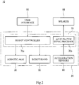
- Fig. 2 is a block diagram illustrating a configuration of a control system of the robot system according to one embodiment of the present disclosure.
- a robot system 10 performs a part of an assembly work of an automobile.
- the robot system 10 performs an attachment work to attach a seat part (a workpiece W) of the automobile which is a work object to the vehicle body.
- the robot system 10 includes a robot 20 which actually performs the work described above to the workpiece W, a user interface 80 which remotely manipulates the robot 20, and a camera 90 which images a work situation of the robot 20 to acquire video information.
- the robot 20 includes a pedestal 21, a robotic arm 30 coupled to the pedestal 21, a robot hand 50 (end effector) which is attached to a tip-end part of the robotic arm 30 and performs the work to the workpiece W, acceleration sensors 60 attached to the robot hand 50, and a controller 70 which controls the robot 20.
- the robot hand 50 and the acceleration sensors 60 are provided inside a black box surrounded by a broken line.
- the robotic arm 30 is an articulated arm having six joints JT1-JT6, and six links 11a-11f serially coupled through these joints.
- the first joint JT1 couples the pedestal 21 to a base-end part of the first link 11a rotatably on an axis extending vertically.
- the second joint JT2 couples a tip-end part of the first link 11a to a base-end part of the second link 11b rotatably on an axis extending horizontally.
- the third joint JT3 couples a tip-end part of the second link 11b to a base-end part of the third link 11c rotatably on an axis extending horizontally.
- the fourth joint JT4 couples a tip-end part of the third link 11c to a base-end part of the fourth link 11d rotatably on an axis extending in the longitudinal direction of the third link 11c.
- the fifth joint JT5 couples a tip-end part of the fourth link 11d to a base-end part of the fifth link 11e rotatably on an axis extending in a direction perpendicular to the longitudinal direction of the fourth link 11d.
- the sixth joint JT6 rotatably couples a tip-end part of the fifth link 11e to a base-end part of the sixth link 11f in a twisting manner.
- the robot hand 50 which performs the work to the workpiece W is attached to a tip-end part of the sixth link 11f (i.e., inside the black box surrounded by the broken line in Fig. 1 ).
- An arm part 31 of the robotic arm 30 is comprised of a coupled body of the links and the joints, comprised of the first joint JT1, the first link 11a, the second joint JT2, the second link 11b, the third joint JT3, and the third link 11c.
- a wrist part 32 of the robotic arm 30 is comprised of a coupled body of the links and the joints, comprised of the fourth joint JT4, the fourth link 11d, the fifth joint JT5, the fifth link 11e, the sixth joint JT6, and the sixth link 11f.
- the robotic arm 30 constitutes a robot body.
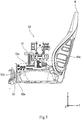
- Fig. 3 is a perspective view when holding the workpiece using the robot system according to one embodiment of the present disclosure.
- Fig. 4 is a plan view of the same, and Fig. 5 is a left side view of the same.
- Fig. 6 is a partially enlarged view of the perspective view of the same, seen from a rear side, and Figs. 7(a) and 7(b) are partially enlarged views of the perspective view of Fig. 3 .
- the workpiece W is the seat to be attached to the automobile, as described above.
- the workpiece W includes a seat part, a backrest part connected to the seat part, and two shaft members AXa and AXb provided along the rear surfaces of the seat part and the backrest part and connecting the seat part and the backrest part to each other.
- the robot hand 50 is attached to the robotic arm 30, and performs the work to the workpiece W.
- the robot hand 50 has a first hand part 51 extending in the illustrated X-direction, and a second hand part 52 coupled to an under side of the first hand part 51.
- the second hand part 52 has a first part 52a extending along an upper surface of the seat part of the workpiece W, a second part 52b connected to a front end of the first part 52a extending along a front surface of the seat part, and a third part 52c connected to a lower end part of the second part 52b and extending along a bottom surface of the seat part.
- the first part 52a described above has two support parts 55a and 55b extending rearwardly (toward positive in the Y-direction in this figure) while inclining downwardly (toward negative in the Z-direction in this figure).
- the two support parts 55a and 55b are each reciprocatable in the X-direction by a given distance.
- a rear end part (a positive end part in the Y-direction in this figure) of each of the two support parts 55a and 55b penetrates a gap formed between the seat part and the backrest part of the workpiece W and reaches the rear surface side of the workpiece W.
- the second hand part 52 holds a front end part of the workpiece W by the first part 52a, the second part 52b, and the third part 52c. Moreover, as illustrated in Fig. 6 , the second hand part 52 holds a rear end part of the workpiece W by the support part 55a contacting one shaft member AXa of the workpiece W from inside and applying an external force outwardly, and the support part 55b contacting the other shaft member AXb of the workpiece W from inside and applying an external force outwardly. Thus, the second hand part 52 can hold the whole workpiece W.
- the acceleration sensor 60 is attached to a location of the first part 52a of the second hand part 52 near the positive end part in the Y-direction (i.e., near the connection of the seat part and the backrest part of the workpiece W), and a location of the second part 52b near the positive end in the X-direction (i.e., a location along the right part of the front surface of the seat part of the workpiece W).
- the acceleration sensor 60 is desirably provided at or near a location contacting the workpiece W.
- the acceleration sensor 60 supplies to the user interface 80 an acceleration signal acquired when the robot hand 50 operates.
- perceptual information is, for example, information which can be sensed by a human, such as sound information and exciting-force information.
- Fig. 8 is a perspective view of the user interface provided to the robot system according to one embodiment of the present disclosure, when seen from the bottom side.
- the user interface 80 is installed so as to be separated from the robot 20 by a given distance, and remotely operates the robotic arm 30 and the robot hand 50 based on a manual operational instruction from an operator.
- the user interface 80 includes a base part 81 formed in a substantially hollow rectangular parallelepiped shape by connecting a plurality of frames to each other, a plurality of master arms 82 attached so as to extend substantially upwardly from the top side of the base part 81, a workpiece model installation part 85 to which tip-end parts of the plurality of master arms 82 are connected at an edge part thereof, and including a principal surface for installing a workpiece model (not illustrated) which imitates the workpiece W, and a speaker 88 (perceptual-information output part) attached to the bottom surface of the top plate of the base part 81.
- Each of the plurality of master arms 82 is fixed to the top surface of the base part 81 by connecting the root part thereto, and has at least one joint. According to such a structure, it is possible for the tip-end parts of the plurality of master arms 82 to freely operate within a given range in the illustrated X-direction, Y-direction, and Z-direction. Thus, the workpiece model installation part 85 is possible to freely operate so as to be interlocked with each of the tip-end parts of the plurality of master arms 82.
- the user interface 80 generates operational information by the operator moving the workpiece model.
- the operational information includes, for example, position information and posture information on the workpiece model.
- the generated operational information is supplied to a robot controller 70a, as illustrated in Fig. 2 .
- the user interface 80 and the robot controller 70a may be connected to each other wiredly or wirelessly.
- the camera 90 is installed in a space where the robot 20 is provided, and images the workpiece W and the robot 20 which performs the work to the workpiece W.
- the camera 90 is installed so that the image captured by the camera 90 includes at least the workpiece W and the robot hand 50.
- the camera 90 is connected to the controller 70.
- the camera 90 and the controller 70 may be connected to each other wiredly or wirelessly.
- the controller 70 includes the robot controller 70a which controls the robotic arm 30 and the robot hand 50 based on the operational information supplied from the user interface 80, and an acceleration signal processor 70b which processes the acceleration signal supplied from the acceleration sensor 60.
- the robot controller 70a controls the robotic arm 30 and the robot hand 50, for example, based on the operational information supplied from the user interface 80. Moreover, the acceleration signal processor 70b filters the acceleration signal to pass only a particular frequency band.
- the controller 70 is comprised of an arithmetic part comprised of a microcontroller, a MPU, a PLC (Programmable Logic Controller), a logic circuit, etc., and a memory comprised of a ROM, a RAM, etc.
- arithmetic part comprised of a microcontroller, a MPU, a PLC (Programmable Logic Controller), a logic circuit, etc.
- a memory comprised of a ROM, a RAM, etc.
- the user interface 80 receives the manual operational instruction from the operator to generate the operational information, and supplies the operational information to the robot controller 70a.
- the operator performs the operational instruction to the user interface 80, while accurately grasping the work situation at the robot 20 end based on the video information outputted from a monitor (not illustrated) and the sound information outputted from the speaker 88.
- the video information outputted from the monitor is an image of the work situation of the robot 20 captured using the camera 90.
- the sound information outputted from the speaker 88 is based on the acceleration signal acquired by the acceleration sensor 60.
- the acceleration sensor 60 detects the acceleration signal when the robot 20 performs the work, and supplies the detected acceleration signal to the acceleration signal processor 70b which is a part of the controller 70.
- the acceleration signal processor 70b filters the acceleration signal to pass only a particular frequency component, and supplies it to the speaker 88.
- the speaker 88 outputs the acceleration signal of the supplied particular frequency component as the sound information.
- the controller 70 controls the robotic arm 30 and the robot hand 50 based on the operational information supplied from the user interface 80.
- the robot system 10 includes the acceleration sensor 60 attached to the robot hand 50, and the speaker 88 (perceptual-information output part) which outputs the acceleration signal from the acceleration sensor 60 as the perceptual information. That is, the robot system 10 according to this embodiment outputs from the speaker 88 the acceleration signal supplied from the acceleration sensor 60 as the perceptual information.
- the acceleration sensor 60 is difficult to collect noise caused by aerial vibration, for example, as compared with a microphone etc.
- the robot system 10 according to this embodiment is possible to remotely manipulate the robot 20 while accurately grasping the work situation at the robot 20 end, thereby ensuring the desired work.
- the acceleration sensor 60 is attached to the location near the connection of the seat part and the backrest part of the workpiece W, and the location along the front surface of the seat part of the workpiece W. That is, in this embodiment, the acceleration sensor 60 is provided at or near the location where the acceleration sensor 60 contacts the workpiece W. Therefore, the above effects of the robot system 10 according to this embodiment can be further improved.
- the perceptual-information output part is the speaker 88 which outputs the acceleration signal as the sound information. Therefore, the robot system 10 according to this embodiment can output clear sound information (i.e., sound information with less noise) which does not include all the noise generated in the factory, for example, as compared with the sound information based on a signal acquired by a conventionally existing microphone. Therefore, the robot system 10 according to this embodiment can certainly give the operator comparatively small sound information, for example, like when the robot hand 50 rubs against the workpiece W.
- the speaker 88 is provided to the user interface 80. Therefore, the operator can certainly catch the sound information outputted from the speaker 88. As a result, the effects of the robot system 10 of the present disclosure can be further improved.
- the acceleration signal processor 70b which filters the acceleration signal acquired by the acceleration sensor 60 to pass only the particular frequency component is further provided, and the speaker 88 outputs the acceleration signal of the particular frequency component as the sound information.
- the speaker 88 (perceptual-information output part) is attached to the bottom surface of the top plate of the base part 81 of the user interface 80, it is not limited in this configuration. That is, the speaker 88 may be attached to other parts of the user interface 80, or may be installed near the user interface 80, without being attached to the user interface 80. Further, the speaker 88 may be installed at the position distant from the user interface 80 instead of near the user interface 80, as long as it can output the sound information with a sufficiently large volume to the extent that the operator can accurately grasp the work situation at the robot 20 end. Note that, in the case of a frequency component of a low band, it is also possible to give the operator the output from the speaker 88 as vibration.
- the perceptual-information output part is the speaker 88 which outputs the sound information
- the perceptual-information output parts may be a headphone which is attached to the operator and outputs the sound information.
- Fig. 9 is a perspective view of the user interface according to one modification of the present disclosure when seen from the top side.
- a grip body 86 having a contour of a substantially rectangular shape in a plan view is installed on an upper surface of the workpiece model installation part 85 of the user interface 80, in order to be gripped by the operator.
- the grip body 86 has two vibrators 88'.
- a motor 89 as illustrated by a broken line is built in each vibrator 88'.
- Each vibrator 88' outputs the exciting-force information by rotating the motor 89, and can give the operator the work situation at the robot 20 end.
- the vibrator 88' is built in the user interface 80, the location at which the vibrator 88' is provided is not limited in particular, as long as it is provided to the user interface 80. That is, the vibrator 88' may be provided to the user interface 80 so that it is attached to an external surface of the user interface 80.
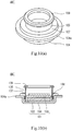
- the perceptual-information output part may be a transducer 88", as illustrated in Fig. 10.
- Figs. 10(a) and 10(b) are views illustrating a transducer according to another modification of the present disclosure, where Fig. 10(a) is a perspective view, and Fig. 10(b) is a cross-sectional view along a plane where the height direction and the width direction intersect with each other.
- the transducer 88" is a perceptual-information output part which can output both the sound information and the exciting-force information, as the perceptual information.
- the transducer 88" includes a magnetic circuit 101, a bobbin 105, a voice coil 106, and a suspension 107.
- the magnetic circuit 101 is mainly comprised of a magnet 102, an inner yoke 103, and an outer yoke 104.
- the bobbin 105 has a cylindrical shape.
- the suspension 107 supports the bobbin 105 so that the bobbin 105 is disposed at a given position of the transducer 88".
- An annular member 109 is provided to a tip end of the bobbin 105. According to such a structure, the bobbin 105 vibrates when electric current flows into the voice coil 106.
- the end effector is the robot hand 50 which performs the work to the workpiece W after holding the workpiece W, it is not limited to this configuration, as long as it performs a certain work to the workpiece.
- the end effector may be a drill for forming an arbitrary hole in the workpiece.
Landscapes
- Engineering & Computer Science (AREA)
- Robotics (AREA)
- Mechanical Engineering (AREA)
- Human Computer Interaction (AREA)
- Multimedia (AREA)
- Manipulator (AREA)
Abstract
Description
- The present disclosure relates to a robot system.
- Conventionally, a robot system is known, which is provided with a robot which performs a work to a workpiece, and a user interface for remotely manipulating the robot. As such a robot system, for example, there is a remote control system disclosed in Patent Document 1.
- The remote control system of Patent Document 1 performs a matching of a to-be-operated device with an operation terminal which manipulates the to-be-operated device from a remote location by a server on a communication network, and remotely manipulates the to-be-operated device from the operation terminal according to the matching to perform a task.
- [Patent Document 1]
JP5177136B2 - Meanwhile, in the remote control system of Patent Document 1, a camera, a microphone, etc. are provided to the to-be-operated device end (i.e., the robot end), and video information, sound information, etc. which are acquired by the camera, the microphone, etc. are supplied to the operation terminal end (i.e., the user interface end). Therefore, the operator remotely operates the robot while grasping a work situation at the robot end to perform the work. However, based on the video information and the sound information supplied at this time, it is difficult for the operator to accurately grasp the work situation at the robot end. For example, in the case of the sound information, since all the noise generated in a factory is supplied, it is difficult to accurately grasp the work situation at the robot end. As a result, there is a problem that the remote control system of Patent Document 1 may be unable to perform a desired work.
- Therefore, one purpose of the present disclosure is to provide a robot system which can ensure a desired work by remotely operating a robot, while accurately grasping a work situation at the robot end.
- In order to solve the above problems, a robot system according to the present disclosure includes a robot configured to perform a work to a workpiece, and a user interface configured to remotely manipulate the robot. The robot includes a robotic arm, an end effector attached to the robotic arm and configured to perform the work to the workpiece, and an acceleration sensor attached to the end effector. The robot system further includes a perceptual-information output part configured to output an acceleration signal from the acceleration sensor as perceptual information.
- According to this configuration, noise in a factory etc. which is unnecessary for grasping a work situation at the robot end can be removed, and the acceleration signal from the acceleration sensor can be outputted from the perceptual-information output part as the perceptual information. As a result, the robot system according to the present disclosure is possible to remotely manipulate the robot while accurately grasping the work situation at the robot end, and certainly perform the desired work.
- The acceleration sensor may be disposed at or near a location where the acceleration sensor contacts the workpiece.
- According to this configuration, the effects of the robot system according to the present disclosure can be further improved.
- The robot system may further include an acceleration signal processor configured to filter the acceleration signal acquired by the acceleration sensor to pass only a particular frequency component. The perceptual-information output part may output the acceleration signal of the particular frequency component as the perceptual information.
- According to this configuration, the effects of the robot system according to the present disclosure can be further improved.
- The perceptual information may be sound information, and the perceptual-information output part may be a speaker configured to output the acceleration signal as the sound information.
- According to this configuration, the perceptual-information output part can output clear sound information (i.e., sound information with less noise) which does not include all the noise generated in the factory as compared with the sound information acquired by, for example, a conventionally existing microphone. This is because the acceleration sensor is difficult to collect noise caused by aerial vibration as compared with the microphone. Therefore, it becomes possible to certainly give an operator comparatively small sound information, for example, like when the end effector rubs against the workpiece.
- The speaker may be provided at or near the user interface.
- According to this configuration, the operator can certainly catch the sound information outputted from the speaker. Therefore, the effects of the robot system according to the present disclosure can be further improved.
- The perceptual information may be exciting-force information, and the perceptual-information output part may be a vibrator configured to output the acceleration signal as the exciting-force information, and may be provided to the user interface.
- According to this configuration, the operator can percept the exciting-force information, and thus it becomes possible to remotely manipulate the robot while accurately grasping the work situation at the robot end, and certainly perform the desired work.
- The present disclosure can provide the robot system which can ensure the desired work by remotely operating the robot, while accurately grasping the work situation at the robot end.
-
-
Fig. 1 is a schematic diagram illustrating an entire configuration of a robot system according to one embodiment of the present disclosure. -
Fig. 2 is a block diagram illustrating a configuration of a control system of the robot system according to one embodiment of the present disclosure. -
Fig. 3 is a perspective view when holding a workpiece using the robot system according to one embodiment of the present disclosure. -
Fig. 4 is a plan view when holding the workpiece using the robot system according to one embodiment of the present disclosure. -
Fig. 5 is a left side view when holding the workpiece using the robot system according to one embodiment of the present disclosure. -
Fig. 6 is a partially enlarged view of the perspective view, seen from the rear side when holding the workpiece using the robot system according to one embodiment of the present disclosure. -
Figs. 7(a) and 7(b) are partially enlarged views of the perspective view when holding the workpiece using the robot system according to one embodiment of the present disclosure. -
Fig. 8 is a perspective view of a user interface provided to the robot system according to one embodiment of the present disclosure, when seen from the bottom side. -
Fig. 9 is a perspective view of the user interface according to one modification of the present disclosure when seen from the top side. -
Figs. 10(a) and 10(b) are views illustrating a transducer according to another modification of the present disclosure, whereFig. 10(a) is a perspective view, andFig. 10(b) is a cross-sectional view along a plane where the height direction and the width direction intersect with each other. - Hereinafter, a robot system according to one embodiment of the present disclosure is described with reference to the drawings.
Fig. 1 is a schematic diagram illustrating the entire configuration of the robot system according to one embodiment of the present disclosure.Fig. 2 is a block diagram illustrating a configuration of a control system of the robot system according to one embodiment of the present disclosure. - A
robot system 10 according to this embodiment performs a part of an assembly work of an automobile. In detail, therobot system 10 performs an attachment work to attach a seat part (a workpiece W) of the automobile which is a work object to the vehicle body. - The
robot system 10 according to this embodiment includes arobot 20 which actually performs the work described above to the workpiece W, auser interface 80 which remotely manipulates therobot 20, and acamera 90 which images a work situation of therobot 20 to acquire video information. - The
robot 20 includes apedestal 21, arobotic arm 30 coupled to thepedestal 21, a robot hand 50 (end effector) which is attached to a tip-end part of therobotic arm 30 and performs the work to the workpiece W,acceleration sensors 60 attached to therobot hand 50, and acontroller 70 which controls therobot 20. Note that, inFig. 1 , therobot hand 50 and theacceleration sensors 60 are provided inside a black box surrounded by a broken line. - As illustrated in
Fig. 1 , therobotic arm 30 is an articulated arm having six joints JT1-JT6, and sixlinks 11a-11f serially coupled through these joints. In detail, the first joint JT1 couples thepedestal 21 to a base-end part of thefirst link 11a rotatably on an axis extending vertically. The second joint JT2 couples a tip-end part of thefirst link 11a to a base-end part of thesecond link 11b rotatably on an axis extending horizontally. The third joint JT3 couples a tip-end part of thesecond link 11b to a base-end part of thethird link 11c rotatably on an axis extending horizontally. The fourth joint JT4 couples a tip-end part of thethird link 11c to a base-end part of thefourth link 11d rotatably on an axis extending in the longitudinal direction of thethird link 11c. The fifth joint JT5 couples a tip-end part of thefourth link 11d to a base-end part of thefifth link 11e rotatably on an axis extending in a direction perpendicular to the longitudinal direction of thefourth link 11d. The sixth joint JT6 rotatably couples a tip-end part of thefifth link 11e to a base-end part of thesixth link 11f in a twisting manner. Therobot hand 50 which performs the work to the workpiece W is attached to a tip-end part of thesixth link 11f (i.e., inside the black box surrounded by the broken line inFig. 1 ). - An
arm part 31 of therobotic arm 30 is comprised of a coupled body of the links and the joints, comprised of the first joint JT1, thefirst link 11a, the second joint JT2, thesecond link 11b, the third joint JT3, and thethird link 11c. Moreover, awrist part 32 of therobotic arm 30 is comprised of a coupled body of the links and the joints, comprised of the fourth joint JT4, thefourth link 11d, the fifth joint JT5, thefifth link 11e, the sixth joint JT6, and thesixth link 11f. Note that therobotic arm 30 constitutes a robot body. - Next, mainly referring to
Figs. 2 to 7 , a structure of therobot hand 50 is described, using a state where the workpiece W is held as one example.Fig. 3 is a perspective view when holding the workpiece using the robot system according to one embodiment of the present disclosure. Moreover,Fig. 4 is a plan view of the same, andFig. 5 is a left side view of the same. Further,Fig. 6 is a partially enlarged view of the perspective view of the same, seen from a rear side, andFigs. 7(a) and 7(b) are partially enlarged views of the perspective view ofFig. 3 . - Here, the workpiece W according to this embodiment is the seat to be attached to the automobile, as described above. The workpiece W includes a seat part, a backrest part connected to the seat part, and two shaft members AXa and AXb provided along the rear surfaces of the seat part and the backrest part and connecting the seat part and the backrest part to each other.
- The
robot hand 50 is attached to therobotic arm 30, and performs the work to the workpiece W. Therobot hand 50 has afirst hand part 51 extending in the illustrated X-direction, and asecond hand part 52 coupled to an under side of thefirst hand part 51. - The
second hand part 52 has afirst part 52a extending along an upper surface of the seat part of the workpiece W, asecond part 52b connected to a front end of thefirst part 52a extending along a front surface of the seat part, and athird part 52c connected to a lower end part of thesecond part 52b and extending along a bottom surface of the seat part. - As illustrated in
Fig. 6 , thefirst part 52a described above has twosupport parts support parts Fig. 6 , a rear end part (a positive end part in the Y-direction in this figure) of each of the twosupport parts - As illustrated in
Fig. 5 , thesecond hand part 52 holds a front end part of the workpiece W by thefirst part 52a, thesecond part 52b, and thethird part 52c. Moreover, as illustrated inFig. 6 , thesecond hand part 52 holds a rear end part of the workpiece W by thesupport part 55a contacting one shaft member AXa of the workpiece W from inside and applying an external force outwardly, and thesupport part 55b contacting the other shaft member AXb of the workpiece W from inside and applying an external force outwardly. Thus, thesecond hand part 52 can hold the whole workpiece W. - As illustrated in
Figs. 7(a) and 7(b) , theacceleration sensor 60 is attached to a location of thefirst part 52a of thesecond hand part 52 near the positive end part in the Y-direction (i.e., near the connection of the seat part and the backrest part of the workpiece W), and a location of thesecond part 52b near the positive end in the X-direction (i.e., a location along the right part of the front surface of the seat part of the workpiece W). Thus, theacceleration sensor 60 is desirably provided at or near a location contacting the workpiece W. - The
acceleration sensor 60 supplies to theuser interface 80 an acceleration signal acquired when therobot hand 50 operates. Here, perceptual information is, for example, information which can be sensed by a human, such as sound information and exciting-force information. - Further, mainly referring to
Figs. 2 and8 , theuser interface 80 according to one embodiment of the present disclosure is described.Fig. 8 is a perspective view of the user interface provided to the robot system according to one embodiment of the present disclosure, when seen from the bottom side. - The
user interface 80 is installed so as to be separated from therobot 20 by a given distance, and remotely operates therobotic arm 30 and therobot hand 50 based on a manual operational instruction from an operator. As illustrated inFig. 8 , theuser interface 80 includes abase part 81 formed in a substantially hollow rectangular parallelepiped shape by connecting a plurality of frames to each other, a plurality ofmaster arms 82 attached so as to extend substantially upwardly from the top side of thebase part 81, a workpiecemodel installation part 85 to which tip-end parts of the plurality ofmaster arms 82 are connected at an edge part thereof, and including a principal surface for installing a workpiece model (not illustrated) which imitates the workpiece W, and a speaker 88 (perceptual-information output part) attached to the bottom surface of the top plate of thebase part 81. - Each of the plurality of
master arms 82 is fixed to the top surface of thebase part 81 by connecting the root part thereto, and has at least one joint. According to such a structure, it is possible for the tip-end parts of the plurality ofmaster arms 82 to freely operate within a given range in the illustrated X-direction, Y-direction, and Z-direction. Thus, the workpiecemodel installation part 85 is possible to freely operate so as to be interlocked with each of the tip-end parts of the plurality ofmaster arms 82. - The
user interface 80 generates operational information by the operator moving the workpiece model. The operational information includes, for example, position information and posture information on the workpiece model. The generated operational information is supplied to arobot controller 70a, as illustrated inFig. 2 . Theuser interface 80 and therobot controller 70a may be connected to each other wiredly or wirelessly. - The
camera 90 is installed in a space where therobot 20 is provided, and images the workpiece W and therobot 20 which performs the work to the workpiece W. Thecamera 90 is installed so that the image captured by thecamera 90 includes at least the workpiece W and therobot hand 50. As illustrated inFig. 1 , in this embodiment, although thecamera 90 is installed so as to image the workpiece W from above, the installed position is not limited in particular. Thecamera 90 is connected to thecontroller 70. Thecamera 90 and thecontroller 70 may be connected to each other wiredly or wirelessly. - As illustrated in the block diagram of
Fig. 2 , thecontroller 70 includes therobot controller 70a which controls therobotic arm 30 and therobot hand 50 based on the operational information supplied from theuser interface 80, and anacceleration signal processor 70b which processes the acceleration signal supplied from theacceleration sensor 60. - The
robot controller 70a controls therobotic arm 30 and therobot hand 50, for example, based on the operational information supplied from theuser interface 80. Moreover, theacceleration signal processor 70b filters the acceleration signal to pass only a particular frequency band. - The
controller 70 is comprised of an arithmetic part comprised of a microcontroller, a MPU, a PLC (Programmable Logic Controller), a logic circuit, etc., and a memory comprised of a ROM, a RAM, etc. - One example of performing the work to the workpiece W using the
robot system 10 according to this embodiment is described. - First, the
user interface 80 receives the manual operational instruction from the operator to generate the operational information, and supplies the operational information to therobot controller 70a. - At this time, the operator performs the operational instruction to the
user interface 80, while accurately grasping the work situation at therobot 20 end based on the video information outputted from a monitor (not illustrated) and the sound information outputted from thespeaker 88. Here, the video information outputted from the monitor is an image of the work situation of therobot 20 captured using thecamera 90. Moreover, the sound information outputted from thespeaker 88 is based on the acceleration signal acquired by theacceleration sensor 60. In detail, theacceleration sensor 60 detects the acceleration signal when therobot 20 performs the work, and supplies the detected acceleration signal to theacceleration signal processor 70b which is a part of thecontroller 70. Next, theacceleration signal processor 70b filters the acceleration signal to pass only a particular frequency component, and supplies it to thespeaker 88. Thespeaker 88 outputs the acceleration signal of the supplied particular frequency component as the sound information. - Then, the
controller 70 controls therobotic arm 30 and therobot hand 50 based on the operational information supplied from theuser interface 80. - The
robot system 10 according to this embodiment includes theacceleration sensor 60 attached to therobot hand 50, and the speaker 88 (perceptual-information output part) which outputs the acceleration signal from theacceleration sensor 60 as the perceptual information. That is, therobot system 10 according to this embodiment outputs from thespeaker 88 the acceleration signal supplied from theacceleration sensor 60 as the perceptual information. Here, theacceleration sensor 60 is difficult to collect noise caused by aerial vibration, for example, as compared with a microphone etc. As a result, therobot system 10 according to this embodiment is possible to remotely manipulate therobot 20 while accurately grasping the work situation at therobot 20 end, thereby ensuring the desired work. - Further, in this embodiment, the
acceleration sensor 60 is attached to the location near the connection of the seat part and the backrest part of the workpiece W, and the location along the front surface of the seat part of the workpiece W. That is, in this embodiment, theacceleration sensor 60 is provided at or near the location where theacceleration sensor 60 contacts the workpiece W. Therefore, the above effects of therobot system 10 according to this embodiment can be further improved. - Further, in this embodiment, the perceptual-information output part is the
speaker 88 which outputs the acceleration signal as the sound information. Therefore, therobot system 10 according to this embodiment can output clear sound information (i.e., sound information with less noise) which does not include all the noise generated in the factory, for example, as compared with the sound information based on a signal acquired by a conventionally existing microphone. Therefore, therobot system 10 according to this embodiment can certainly give the operator comparatively small sound information, for example, like when therobot hand 50 rubs against the workpiece W. - Moreover, in this embodiment, the
speaker 88 is provided to theuser interface 80. Therefore, the operator can certainly catch the sound information outputted from thespeaker 88. As a result, the effects of therobot system 10 of the present disclosure can be further improved. - Further, in this embodiment, the
acceleration signal processor 70b which filters the acceleration signal acquired by theacceleration sensor 60 to pass only the particular frequency component is further provided, and thespeaker 88 outputs the acceleration signal of the particular frequency component as the sound information. - According to this configuration, the effects of the
robot system 10 of the present disclosure can be further improved. - Although in one embodiment described above the speaker 88 (perceptual-information output part) is attached to the bottom surface of the top plate of the
base part 81 of theuser interface 80, it is not limited in this configuration. That is, thespeaker 88 may be attached to other parts of theuser interface 80, or may be installed near theuser interface 80, without being attached to theuser interface 80. Further, thespeaker 88 may be installed at the position distant from theuser interface 80 instead of near theuser interface 80, as long as it can output the sound information with a sufficiently large volume to the extent that the operator can accurately grasp the work situation at therobot 20 end. Note that, in the case of a frequency component of a low band, it is also possible to give the operator the output from thespeaker 88 as vibration. - Although in one embodiment described above the perceptual-information output part is the
speaker 88 which outputs the sound information, it is not limited to this configuration. For example, the perceptual-information output parts may be a headphone which is attached to the operator and outputs the sound information. - Moreover, the perceptual-information output part is not limited to the
speaker 88 and the headphone which outputs the sound information, and, for example, it may be a vibrator 88' which outputs exciting-force information, as illustrated inFig. 9. Fig. 9 is a perspective view of the user interface according to one modification of the present disclosure when seen from the top side. As illustrated inFig. 9 , in this modification, agrip body 86 having a contour of a substantially rectangular shape in a plan view is installed on an upper surface of the workpiecemodel installation part 85 of theuser interface 80, in order to be gripped by the operator. Thegrip body 86 has two vibrators 88'. Amotor 89 as illustrated by a broken line is built in each vibrator 88'. Each vibrator 88' outputs the exciting-force information by rotating themotor 89, and can give the operator the work situation at therobot 20 end. Note that, although in this modification the vibrator 88' is built in theuser interface 80, the location at which the vibrator 88' is provided is not limited in particular, as long as it is provided to theuser interface 80. That is, the vibrator 88' may be provided to theuser interface 80 so that it is attached to an external surface of theuser interface 80. - Moreover, for example, the perceptual-information output part may be a
transducer 88", as illustrated inFig. 10. Figs. 10(a) and 10(b) are views illustrating a transducer according to another modification of the present disclosure, whereFig. 10(a) is a perspective view, andFig. 10(b) is a cross-sectional view along a plane where the height direction and the width direction intersect with each other. Thetransducer 88" is a perceptual-information output part which can output both the sound information and the exciting-force information, as the perceptual information. - The
transducer 88" includes amagnetic circuit 101, abobbin 105, avoice coil 106, and asuspension 107. Themagnetic circuit 101 is mainly comprised of amagnet 102, aninner yoke 103, and anouter yoke 104. Thebobbin 105 has a cylindrical shape. Thesuspension 107 supports thebobbin 105 so that thebobbin 105 is disposed at a given position of thetransducer 88". Anannular member 109 is provided to a tip end of thebobbin 105. According to such a structure, thebobbin 105 vibrates when electric current flows into thevoice coil 106. It becomes possible to give the operator at least one of the sound information and the exciting-force information by attaching and using such atransducer 88" to theuser interface 80 in the same way as thespeaker 88 illustrated inFig. 8 so that, for example, theannular member 109 contacts to the top plate of theuser interface 80. - Further, although in one embodiment described above the end effector is the
robot hand 50 which performs the work to the workpiece W after holding the workpiece W, it is not limited to this configuration, as long as it performs a certain work to the workpiece. For example, the end effector may be a drill for forming an arbitrary hole in the workpiece. - It is apparent for a person skilled in the art that many improvements and other embodiments of the present disclosure are possible from the above description. Therefore, the above description is to be interpreted only as illustration, and it is provided in order to teach a person skilled in the art the best mode that implements the present disclosure. The details of the structure and/or the functions may be changed substantially, without departing from the spirit of the present disclosure.
-
- 10
- Robot System
- 20
- Robot
- 21
- Pedestal
- 30
- Robotic Arm
- 31
- Arm Part
- 32
- Wrist Part
- 50
- Robot Hand
- 51
- First Hand Part
- 52
- Second Hand Part
- 52a
- First Part
- 52b
- Second Part
- 52c
- Third Part
- 55a, 55b
- Support Part
- 60
- Acceleration Sensor
- 70
- Controller
- 70a
- Robot Controller
- 70b
- Acceleration Signal Processor
- 80
- User Interface
- 81
- Base Part
- 82
- Master Arm
- 85
- Workpiece Model Installation Part
- 88
- Speaker
- 88'
- Vibrator
- 88"
- Transducer
- 90
- Camera
- W
- Workpiece
Claims (6)
- A robot system comprising a robot configured to perform a work to a workpiece, and a user interface configured to remotely manipulate the robot,
wherein the robot includes:a robotic arm;an end effector attached to the robotic arm and configured to perform the work to the workpiece; andan acceleration sensor attached to the end effector, andwherein the robot system further comprises a perceptual-information output part configured to output an acceleration signal from the acceleration sensor as perceptual information. - The robot system of claim 1, wherein the acceleration sensor is disposed at or near a location where the acceleration sensor contacts the workpiece.
- The robot system of claim 1 or 2, further comprising an acceleration signal processor configured to filter the acceleration signal acquired by the acceleration sensor to pass only a particular frequency component,
wherein the perceptual-information output part outputs the acceleration signal of the particular frequency component as the perceptual information. - The robot system of any one of claims 1 to 3, wherein the perceptual information is sound information, and the perceptual-information output part is a speaker configured to output the acceleration signal as the sound information.
- The robot system of claim 4, wherein the speaker is provided at or near the user interface.
- The robot system of any one of claims 1 to 3, wherein the perceptual information is exciting-force information, and the perceptual-information output part is a vibrator configured to output the acceleration signal as the exciting-force information, and is provided to the user interface.
Applications Claiming Priority (2)
| Application Number | Priority Date | Filing Date | Title |
|---|---|---|---|
| JP2017100368A JP7223493B2 (en) | 2017-05-19 | 2017-05-19 | robot system |
| PCT/JP2018/018919 WO2018212234A1 (en) | 2017-05-19 | 2018-05-16 | Robot system |
Publications (3)
| Publication Number | Publication Date |
|---|---|
| EP3626400A1 true EP3626400A1 (en) | 2020-03-25 |
| EP3626400A4 EP3626400A4 (en) | 2020-10-14 |
| EP3626400B1 EP3626400B1 (en) | 2025-03-12 |
Family
ID=64273952
Family Applications (1)
| Application Number | Title | Priority Date | Filing Date |
|---|---|---|---|
| EP18801292.6A Active EP3626400B1 (en) | 2017-05-19 | 2018-05-16 | Robot system |
Country Status (5)
| Country | Link |
|---|---|
| US (1) | US11738468B2 (en) |
| EP (1) | EP3626400B1 (en) |
| JP (1) | JP7223493B2 (en) |
| CN (1) | CN110662630A (en) |
| WO (1) | WO2018212234A1 (en) |
Cited By (1)
| Publication number | Priority date | Publication date | Assignee | Title |
|---|---|---|---|---|
| EP4628260A4 (en) * | 2022-11-28 | 2026-04-15 | Sumitomo Heavy Industries | Remote Working Support System |
Families Citing this family (1)
| Publication number | Priority date | Publication date | Assignee | Title |
|---|---|---|---|---|
| JP2025140407A (en) * | 2024-03-14 | 2025-09-29 | セイコーエプソン株式会社 | Robot, control method of robot and program for controlling robot |
Family Cites Families (18)
| Publication number | Priority date | Publication date | Assignee | Title |
|---|---|---|---|---|
| DE69223854T2 (en) * | 1991-06-14 | 1998-05-20 | Honeywell Inc | Proportional mode - manual control with force feedback |
| US20070288124A1 (en) * | 2004-08-25 | 2007-12-13 | Kabushiki Kaisha Yaskawa Denki | Evaluating System And Evaluating Method Of Robot |
| JP5177136B2 (en) | 2007-05-09 | 2013-04-03 | 日本電気株式会社 | REMOTE OPERATION SYSTEM, SERVER, REMOTE OPERATION DEVICE, REMOTE OPERATION SERVICE PROVIDING METHOD |
| JP2012171088A (en) * | 2011-02-24 | 2012-09-10 | Olympus Corp | Master operation input device, and master-slave manipulator |
| US20120244969A1 (en) * | 2011-03-25 | 2012-09-27 | May Patents Ltd. | System and Method for a Motion Sensing Device |
| US9505133B2 (en) * | 2013-12-13 | 2016-11-29 | Canon Kabushiki Kaisha | Robot apparatus, robot controlling method, program and recording medium |
| EP3017920B1 (en) * | 2014-11-07 | 2017-08-23 | Comau S.p.A. | An industrial robot and a method for controlling an industrial robot |
| JP6480224B2 (en) * | 2015-03-19 | 2019-03-06 | 株式会社イシダ | Mass measuring device |
| JP6582549B2 (en) | 2015-05-25 | 2019-10-02 | ソニー株式会社 | Vibration detection module, vibration detection device, vibration detection method, and surgical system |
| US20170010671A1 (en) * | 2015-07-10 | 2017-01-12 | 8982406 Canada Inc. | Haptic interface with localized feedback |
| KR102055317B1 (en) * | 2015-08-25 | 2020-01-22 | 카와사키 주코교 카부시키 카이샤 | Robot system |
| JP6174654B2 (en) * | 2015-10-15 | 2017-08-02 | ファナック株式会社 | Robot system with function to calculate sensor position and orientation |
| CN108496345B (en) * | 2016-01-19 | 2021-02-26 | 株式会社精好 | Pen type calling-in and calling-out communication device |
| JP6748019B2 (en) * | 2017-04-10 | 2020-08-26 | ファナック株式会社 | Robot system having external force display function, processing device, and teaching operation panel |
| US11453129B2 (en) * | 2018-01-17 | 2022-09-27 | Toyota Research Institute, Inc. | User assisting robot for shopping applications |
| MX2020008638A (en) * | 2018-02-28 | 2020-09-21 | Nissan Motor | Abnormality type determining device and abnormality type determining method. |
| JP6836544B2 (en) * | 2018-05-09 | 2021-03-03 | ファナック株式会社 | Control system and driven body control method |
| JP7143633B2 (en) * | 2018-05-28 | 2022-09-29 | セイコーエプソン株式会社 | ROBOT SYSTEM, CONTROL DEVICE AND CONTROL METHOD |
-
2017
- 2017-05-19 JP JP2017100368A patent/JP7223493B2/en active Active
-
2018
- 2018-05-16 CN CN201880032426.1A patent/CN110662630A/en active Pending
- 2018-05-16 US US16/613,288 patent/US11738468B2/en active Active
- 2018-05-16 WO PCT/JP2018/018919 patent/WO2018212234A1/en not_active Ceased
- 2018-05-16 EP EP18801292.6A patent/EP3626400B1/en active Active
Cited By (1)
| Publication number | Priority date | Publication date | Assignee | Title |
|---|---|---|---|---|
| EP4628260A4 (en) * | 2022-11-28 | 2026-04-15 | Sumitomo Heavy Industries | Remote Working Support System |
Also Published As
| Publication number | Publication date |
|---|---|
| US20210114229A1 (en) | 2021-04-22 |
| JP2018192593A (en) | 2018-12-06 |
| EP3626400B1 (en) | 2025-03-12 |
| JP7223493B2 (en) | 2023-02-16 |
| EP3626400A4 (en) | 2020-10-14 |
| US11738468B2 (en) | 2023-08-29 |
| WO2018212234A1 (en) | 2018-11-22 |
| CN110662630A (en) | 2020-01-07 |
Similar Documents
| Publication | Publication Date | Title |
|---|---|---|
| JP7381632B2 (en) | Remote control of robot platforms based on multimodal sensory data | |
| US11697209B1 (en) | Coordinate mapping for motion control | |
| TWI609748B (en) | Remote operating robot system | |
| US12263596B2 (en) | Autonomous and semi-autonomous control of aerial robotic systems | |
| US11717969B1 (en) | Cooperative high-capacity and high-dexterity manipulators | |
| US20180029221A1 (en) | Robot and robot system | |
| US20150336276A1 (en) | Personal robot | |
| EP3626400B1 (en) | Robot system | |
| JP2018167334A (en) | Teaching device and teaching method | |
| US11639003B2 (en) | Teaching device and robot system | |
| CN110650824A (en) | Remote operation robot system | |
| JP2019093506A (en) | Basic posture setting device and basic posture setting method | |
| CN111093911A (en) | Robot system and method for operating the same | |
| TW202122225A (en) | System and method for robotic bin picking using advanced scanning techniques | |
| JP2004351533A (en) | Robot system | |
| CN110612182A (en) | Operating device and operating system | |
| JP2014073540A (en) | Robot and robot system | |
| EP4027930A1 (en) | Methods and systems for assigning force vectors to robotic tasks | |
| CN105710856A (en) | Remote motion sensing control robot | |
| CN116635190B (en) | Robot systems and robot operation methods | |
| CN113856935A (en) | Man-machine cooperative control spraying system and method | |
| US12441000B2 (en) | Robot system and robot working method | |
| US12440995B1 (en) | Virtual barriers for remotely operated equipment | |
| CN218557148U (en) | Robot alarm feedback system and industrial robot | |
| CN115139294A (en) | Robot control method, robot system, and storage medium |
Legal Events
| Date | Code | Title | Description |
|---|---|---|---|
| STAA | Information on the status of an ep patent application or granted ep patent |
Free format text: STATUS: THE INTERNATIONAL PUBLICATION HAS BEEN MADE |
|
| PUAI | Public reference made under article 153(3) epc to a published international application that has entered the european phase |
Free format text: ORIGINAL CODE: 0009012 |
|
| STAA | Information on the status of an ep patent application or granted ep patent |
Free format text: STATUS: REQUEST FOR EXAMINATION WAS MADE |
|
| 17P | Request for examination filed |
Effective date: 20191115 |
|
| AK | Designated contracting states |
Kind code of ref document: A1 Designated state(s): AL AT BE BG CH CY CZ DE DK EE ES FI FR GB GR HR HU IE IS IT LI LT LU LV MC MK MT NL NO PL PT RO RS SE SI SK SM TR |
|
| AX | Request for extension of the european patent |
Extension state: BA ME |
|
| DAV | Request for validation of the european patent (deleted) | ||
| DAX | Request for extension of the european patent (deleted) | ||
| A4 | Supplementary search report drawn up and despatched |
Effective date: 20200916 |
|
| RIC1 | Information provided on ipc code assigned before grant |
Ipc: B25J 3/00 20060101AFI20200910BHEP Ipc: B25J 13/00 20060101ALI20200910BHEP |
|
| STAA | Information on the status of an ep patent application or granted ep patent |
Free format text: STATUS: EXAMINATION IS IN PROGRESS |
|
| 17Q | First examination report despatched |
Effective date: 20210917 |
|
| GRAP | Despatch of communication of intention to grant a patent |
Free format text: ORIGINAL CODE: EPIDOSNIGR1 |
|
| STAA | Information on the status of an ep patent application or granted ep patent |
Free format text: STATUS: GRANT OF PATENT IS INTENDED |
|
| INTG | Intention to grant announced |
Effective date: 20241113 |
|
| GRAS | Grant fee paid |
Free format text: ORIGINAL CODE: EPIDOSNIGR3 |
|
| GRAA | (expected) grant |
Free format text: ORIGINAL CODE: 0009210 |
|
| STAA | Information on the status of an ep patent application or granted ep patent |
Free format text: STATUS: THE PATENT HAS BEEN GRANTED |
|
| AK | Designated contracting states |
Kind code of ref document: B1 Designated state(s): AL AT BE BG CH CY CZ DE DK EE ES FI FR GB GR HR HU IE IS IT LI LT LU LV MC MK MT NL NO PL PT RO RS SE SI SK SM TR |
|
| REG | Reference to a national code |
Ref country code: GB Ref legal event code: FG4D |
|
| REG | Reference to a national code |
Ref country code: CH Ref legal event code: EP |
|
| REG | Reference to a national code |
Ref country code: DE Ref legal event code: R096 Ref document number: 602018080075 Country of ref document: DE |
|
| REG | Reference to a national code |
Ref country code: IE Ref legal event code: FG4D |
|
| PG25 | Lapsed in a contracting state [announced via postgrant information from national office to epo] |
Ref country code: RS Free format text: LAPSE BECAUSE OF FAILURE TO SUBMIT A TRANSLATION OF THE DESCRIPTION OR TO PAY THE FEE WITHIN THE PRESCRIBED TIME-LIMIT Effective date: 20250612 |
|
| PG25 | Lapsed in a contracting state [announced via postgrant information from national office to epo] |
Ref country code: FI Free format text: LAPSE BECAUSE OF FAILURE TO SUBMIT A TRANSLATION OF THE DESCRIPTION OR TO PAY THE FEE WITHIN THE PRESCRIBED TIME-LIMIT Effective date: 20250312 |
|
| PG25 | Lapsed in a contracting state [announced via postgrant information from national office to epo] |
Ref country code: ES Free format text: LAPSE BECAUSE OF FAILURE TO SUBMIT A TRANSLATION OF THE DESCRIPTION OR TO PAY THE FEE WITHIN THE PRESCRIBED TIME-LIMIT Effective date: 20250312 |
|
| REG | Reference to a national code |
Ref country code: LT Ref legal event code: MG9D |
|
| PG25 | Lapsed in a contracting state [announced via postgrant information from national office to epo] |
Ref country code: NO Free format text: LAPSE BECAUSE OF FAILURE TO SUBMIT A TRANSLATION OF THE DESCRIPTION OR TO PAY THE FEE WITHIN THE PRESCRIBED TIME-LIMIT Effective date: 20250612 |
|
| PG25 | Lapsed in a contracting state [announced via postgrant information from national office to epo] |
Ref country code: HR Free format text: LAPSE BECAUSE OF FAILURE TO SUBMIT A TRANSLATION OF THE DESCRIPTION OR TO PAY THE FEE WITHIN THE PRESCRIBED TIME-LIMIT Effective date: 20250312 |
|
| REG | Reference to a national code |
Ref country code: NL Ref legal event code: MP Effective date: 20250312 |
|
| PG25 | Lapsed in a contracting state [announced via postgrant information from national office to epo] |
Ref country code: LV Free format text: LAPSE BECAUSE OF FAILURE TO SUBMIT A TRANSLATION OF THE DESCRIPTION OR TO PAY THE FEE WITHIN THE PRESCRIBED TIME-LIMIT Effective date: 20250312 |
|
| PG25 | Lapsed in a contracting state [announced via postgrant information from national office to epo] |
Ref country code: GR Free format text: LAPSE BECAUSE OF FAILURE TO SUBMIT A TRANSLATION OF THE DESCRIPTION OR TO PAY THE FEE WITHIN THE PRESCRIBED TIME-LIMIT Effective date: 20250613 Ref country code: BG Free format text: LAPSE BECAUSE OF FAILURE TO SUBMIT A TRANSLATION OF THE DESCRIPTION OR TO PAY THE FEE WITHIN THE PRESCRIBED TIME-LIMIT Effective date: 20250312 |
|
| REG | Reference to a national code |
Ref country code: AT Ref legal event code: MK05 Ref document number: 1774626 Country of ref document: AT Kind code of ref document: T Effective date: 20250312 |
|
| PG25 | Lapsed in a contracting state [announced via postgrant information from national office to epo] |
Ref country code: NL Free format text: LAPSE BECAUSE OF FAILURE TO SUBMIT A TRANSLATION OF THE DESCRIPTION OR TO PAY THE FEE WITHIN THE PRESCRIBED TIME-LIMIT Effective date: 20250312 |
|
| PG25 | Lapsed in a contracting state [announced via postgrant information from national office to epo] |
Ref country code: SE Free format text: LAPSE BECAUSE OF FAILURE TO SUBMIT A TRANSLATION OF THE DESCRIPTION OR TO PAY THE FEE WITHIN THE PRESCRIBED TIME-LIMIT Effective date: 20250312 |
|
| PG25 | Lapsed in a contracting state [announced via postgrant information from national office to epo] |
Ref country code: SM Free format text: LAPSE BECAUSE OF FAILURE TO SUBMIT A TRANSLATION OF THE DESCRIPTION OR TO PAY THE FEE WITHIN THE PRESCRIBED TIME-LIMIT Effective date: 20250312 |
|
| PG25 | Lapsed in a contracting state [announced via postgrant information from national office to epo] |
Ref country code: PT Free format text: LAPSE BECAUSE OF FAILURE TO SUBMIT A TRANSLATION OF THE DESCRIPTION OR TO PAY THE FEE WITHIN THE PRESCRIBED TIME-LIMIT Effective date: 20250714 |
|
| PG25 | Lapsed in a contracting state [announced via postgrant information from national office to epo] |
Ref country code: PL Free format text: LAPSE BECAUSE OF FAILURE TO SUBMIT A TRANSLATION OF THE DESCRIPTION OR TO PAY THE FEE WITHIN THE PRESCRIBED TIME-LIMIT Effective date: 20250312 Ref country code: IT Free format text: LAPSE BECAUSE OF FAILURE TO SUBMIT A TRANSLATION OF THE DESCRIPTION OR TO PAY THE FEE WITHIN THE PRESCRIBED TIME-LIMIT Effective date: 20250312 |
|
| PG25 | Lapsed in a contracting state [announced via postgrant information from national office to epo] |
Ref country code: AT Free format text: LAPSE BECAUSE OF FAILURE TO SUBMIT A TRANSLATION OF THE DESCRIPTION OR TO PAY THE FEE WITHIN THE PRESCRIBED TIME-LIMIT Effective date: 20250312 |
|
| PG25 | Lapsed in a contracting state [announced via postgrant information from national office to epo] |
Ref country code: CZ Free format text: LAPSE BECAUSE OF FAILURE TO SUBMIT A TRANSLATION OF THE DESCRIPTION OR TO PAY THE FEE WITHIN THE PRESCRIBED TIME-LIMIT Effective date: 20250312 Ref country code: EE Free format text: LAPSE BECAUSE OF FAILURE TO SUBMIT A TRANSLATION OF THE DESCRIPTION OR TO PAY THE FEE WITHIN THE PRESCRIBED TIME-LIMIT Effective date: 20250312 |
|
| PG25 | Lapsed in a contracting state [announced via postgrant information from national office to epo] |
Ref country code: RO Free format text: LAPSE BECAUSE OF FAILURE TO SUBMIT A TRANSLATION OF THE DESCRIPTION OR TO PAY THE FEE WITHIN THE PRESCRIBED TIME-LIMIT Effective date: 20250312 |
|
| PG25 | Lapsed in a contracting state [announced via postgrant information from national office to epo] |
Ref country code: SK Free format text: LAPSE BECAUSE OF FAILURE TO SUBMIT A TRANSLATION OF THE DESCRIPTION OR TO PAY THE FEE WITHIN THE PRESCRIBED TIME-LIMIT Effective date: 20250312 |
|
| PG25 | Lapsed in a contracting state [announced via postgrant information from national office to epo] |
Ref country code: IS Free format text: LAPSE BECAUSE OF FAILURE TO SUBMIT A TRANSLATION OF THE DESCRIPTION OR TO PAY THE FEE WITHIN THE PRESCRIBED TIME-LIMIT Effective date: 20250712 |
|
| REG | Reference to a national code |
Ref country code: DE Ref legal event code: R097 Ref document number: 602018080075 Country of ref document: DE |
|
| REG | Reference to a national code |
Ref country code: CH Ref legal event code: H13 Free format text: ST27 STATUS EVENT CODE: U-0-0-H10-H13 (AS PROVIDED BY THE NATIONAL OFFICE) Effective date: 20251223 |
|
| PG25 | Lapsed in a contracting state [announced via postgrant information from national office to epo] |
Ref country code: DK Free format text: LAPSE BECAUSE OF FAILURE TO SUBMIT A TRANSLATION OF THE DESCRIPTION OR TO PAY THE FEE WITHIN THE PRESCRIBED TIME-LIMIT Effective date: 20250312 |
|
| PG25 | Lapsed in a contracting state [announced via postgrant information from national office to epo] |
Ref country code: LU Free format text: LAPSE BECAUSE OF NON-PAYMENT OF DUE FEES Effective date: 20250516 |
|
| PLBE | No opposition filed within time limit |
Free format text: ORIGINAL CODE: 0009261 |
|
| STAA | Information on the status of an ep patent application or granted ep patent |
Free format text: STATUS: NO OPPOSITION FILED WITHIN TIME LIMIT |
|
| PG25 | Lapsed in a contracting state [announced via postgrant information from national office to epo] |
Ref country code: CH Free format text: LAPSE BECAUSE OF NON-PAYMENT OF DUE FEES Effective date: 20250531 |
|
| REG | Reference to a national code |
Ref country code: CH Ref legal event code: L10 Free format text: ST27 STATUS EVENT CODE: U-0-0-L10-L00 (AS PROVIDED BY THE NATIONAL OFFICE) Effective date: 20260121 |
|
| REG | Reference to a national code |
Ref country code: BE Ref legal event code: MM Effective date: 20250531 |
|
| PG25 | Lapsed in a contracting state [announced via postgrant information from national office to epo] |
Ref country code: MC Free format text: LAPSE BECAUSE OF FAILURE TO SUBMIT A TRANSLATION OF THE DESCRIPTION OR TO PAY THE FEE WITHIN THE PRESCRIBED TIME-LIMIT Effective date: 20250312 |
|
| 26N | No opposition filed |
Effective date: 20251215 |
|
| GBPC | Gb: european patent ceased through non-payment of renewal fee |
Effective date: 20250612 |
|
| PG25 | Lapsed in a contracting state [announced via postgrant information from national office to epo] |
Ref country code: GB Free format text: LAPSE BECAUSE OF NON-PAYMENT OF DUE FEES Effective date: 20250612 |
|
| PG25 | Lapsed in a contracting state [announced via postgrant information from national office to epo] |
Ref country code: IE Free format text: LAPSE BECAUSE OF NON-PAYMENT OF DUE FEES Effective date: 20250516 |
|
| PG25 | Lapsed in a contracting state [announced via postgrant information from national office to epo] |
Ref country code: BE Free format text: LAPSE BECAUSE OF NON-PAYMENT OF DUE FEES Effective date: 20250531 |
|
| PG25 | Lapsed in a contracting state [announced via postgrant information from national office to epo] |
Ref country code: FR Free format text: LAPSE BECAUSE OF NON-PAYMENT OF DUE FEES Effective date: 20250531 |
|
| PG25 | Lapsed in a contracting state [announced via postgrant information from national office to epo] |
Ref country code: LT Free format text: LAPSE BECAUSE OF FAILURE TO SUBMIT A TRANSLATION OF THE DESCRIPTION OR TO PAY THE FEE WITHIN THE PRESCRIBED TIME-LIMIT Effective date: 20250312 |
|
| PGFP | Annual fee paid to national office [announced via postgrant information from national office to epo] |
Ref country code: DE Payment date: 20260402 Year of fee payment: 9 |
|
| PG25 | Lapsed in a contracting state [announced via postgrant information from national office to epo] |
Ref country code: CY Free format text: LAPSE BECAUSE OF FAILURE TO SUBMIT A TRANSLATION OF THE DESCRIPTION OR TO PAY THE FEE WITHIN THE PRESCRIBED TIME-LIMIT Effective date: 20250312 |