EP3625472B1 - Method for controlling a power train for thermal regulation of a hydraulic circuit - Google Patents
Method for controlling a power train for thermal regulation of a hydraulic circuit Download PDFInfo
- Publication number
- EP3625472B1 EP3625472B1 EP18719979.9A EP18719979A EP3625472B1 EP 3625472 B1 EP3625472 B1 EP 3625472B1 EP 18719979 A EP18719979 A EP 18719979A EP 3625472 B1 EP3625472 B1 EP 3625472B1
- Authority
- EP
- European Patent Office
- Prior art keywords
- torque
- motor
- control
- temperature
- actuating fluid
- Prior art date
- Legal status (The legal status is an assumption and is not a legal conclusion. Google has not performed a legal analysis and makes no representation as to the accuracy of the status listed.)
- Active
Links
- 238000000034 method Methods 0.000 title claims description 48
- 230000033228 biological regulation Effects 0.000 title description 6
- 239000012530 fluid Substances 0.000 claims description 61
- 230000008878 coupling Effects 0.000 claims description 36
- 238000010168 coupling process Methods 0.000 claims description 36
- 238000005859 coupling reaction Methods 0.000 claims description 36
- 238000005461 lubrication Methods 0.000 claims description 16
- 230000004044 response Effects 0.000 claims description 12
- 239000006185 dispersion Substances 0.000 claims description 9
- 230000006870 function Effects 0.000 description 15
- 230000001276 controlling effect Effects 0.000 description 14
- 239000010687 lubricating oil Substances 0.000 description 7
- 230000005540 biological transmission Effects 0.000 description 5
- 230000001133 acceleration Effects 0.000 description 3
- 238000009529 body temperature measurement Methods 0.000 description 3
- 230000008901 benefit Effects 0.000 description 2
- 230000000881 depressing effect Effects 0.000 description 2
- 238000010586 diagram Methods 0.000 description 2
- 230000000694 effects Effects 0.000 description 2
- 230000017525 heat dissipation Effects 0.000 description 2
- 230000001050 lubricating effect Effects 0.000 description 2
- 230000015654 memory Effects 0.000 description 2
- 230000008859 change Effects 0.000 description 1
- 238000002485 combustion reaction Methods 0.000 description 1
- 238000001816 cooling Methods 0.000 description 1
- 230000002542 deteriorative effect Effects 0.000 description 1
- 238000006073 displacement reaction Methods 0.000 description 1
- 238000005259 measurement Methods 0.000 description 1
- 230000004048 modification Effects 0.000 description 1
- 238000012986 modification Methods 0.000 description 1
- 239000003921 oil Substances 0.000 description 1
- 230000008569 process Effects 0.000 description 1
- 230000001105 regulatory effect Effects 0.000 description 1
Images

Classifications
-
- F—MECHANICAL ENGINEERING; LIGHTING; HEATING; WEAPONS; BLASTING
- F16—ENGINEERING ELEMENTS AND UNITS; GENERAL MEASURES FOR PRODUCING AND MAINTAINING EFFECTIVE FUNCTIONING OF MACHINES OR INSTALLATIONS; THERMAL INSULATION IN GENERAL
- F16D—COUPLINGS FOR TRANSMITTING ROTATION; CLUTCHES; BRAKES
- F16D48/00—External control of clutches
- F16D48/06—Control by electric or electronic means, e.g. of fluid pressure
- F16D48/066—Control of fluid pressure, e.g. using an accumulator
-
- F—MECHANICAL ENGINEERING; LIGHTING; HEATING; WEAPONS; BLASTING
- F16—ENGINEERING ELEMENTS AND UNITS; GENERAL MEASURES FOR PRODUCING AND MAINTAINING EFFECTIVE FUNCTIONING OF MACHINES OR INSTALLATIONS; THERMAL INSULATION IN GENERAL
- F16D—COUPLINGS FOR TRANSMITTING ROTATION; CLUTCHES; BRAKES
- F16D2500/00—External control of clutches by electric or electronic means
- F16D2500/10—System to be controlled
- F16D2500/102—Actuator
- F16D2500/1026—Hydraulic
-
- F—MECHANICAL ENGINEERING; LIGHTING; HEATING; WEAPONS; BLASTING
- F16—ENGINEERING ELEMENTS AND UNITS; GENERAL MEASURES FOR PRODUCING AND MAINTAINING EFFECTIVE FUNCTIONING OF MACHINES OR INSTALLATIONS; THERMAL INSULATION IN GENERAL
- F16D—COUPLINGS FOR TRANSMITTING ROTATION; CLUTCHES; BRAKES
- F16D2500/00—External control of clutches by electric or electronic means
- F16D2500/10—System to be controlled
- F16D2500/104—Clutch
- F16D2500/10406—Clutch position
- F16D2500/10412—Transmission line of a vehicle
-
- F—MECHANICAL ENGINEERING; LIGHTING; HEATING; WEAPONS; BLASTING
- F16—ENGINEERING ELEMENTS AND UNITS; GENERAL MEASURES FOR PRODUCING AND MAINTAINING EFFECTIVE FUNCTIONING OF MACHINES OR INSTALLATIONS; THERMAL INSULATION IN GENERAL
- F16D—COUPLINGS FOR TRANSMITTING ROTATION; CLUTCHES; BRAKES
- F16D2500/00—External control of clutches by electric or electronic means
- F16D2500/30—Signal inputs
- F16D2500/304—Signal inputs from the clutch
- F16D2500/30406—Clutch slip
-
- F—MECHANICAL ENGINEERING; LIGHTING; HEATING; WEAPONS; BLASTING
- F16—ENGINEERING ELEMENTS AND UNITS; GENERAL MEASURES FOR PRODUCING AND MAINTAINING EFFECTIVE FUNCTIONING OF MACHINES OR INSTALLATIONS; THERMAL INSULATION IN GENERAL
- F16D—COUPLINGS FOR TRANSMITTING ROTATION; CLUTCHES; BRAKES
- F16D2500/00—External control of clutches by electric or electronic means
- F16D2500/30—Signal inputs
- F16D2500/304—Signal inputs from the clutch
- F16D2500/3041—Signal inputs from the clutch from the input shaft
- F16D2500/30412—Torque of the input shaft
-
- F—MECHANICAL ENGINEERING; LIGHTING; HEATING; WEAPONS; BLASTING
- F16—ENGINEERING ELEMENTS AND UNITS; GENERAL MEASURES FOR PRODUCING AND MAINTAINING EFFECTIVE FUNCTIONING OF MACHINES OR INSTALLATIONS; THERMAL INSULATION IN GENERAL
- F16D—COUPLINGS FOR TRANSMITTING ROTATION; CLUTCHES; BRAKES
- F16D2500/00—External control of clutches by electric or electronic means
- F16D2500/30—Signal inputs
- F16D2500/304—Signal inputs from the clutch
- F16D2500/3042—Signal inputs from the clutch from the output shaft
- F16D2500/30421—Torque of the output shaft
-
- F—MECHANICAL ENGINEERING; LIGHTING; HEATING; WEAPONS; BLASTING
- F16—ENGINEERING ELEMENTS AND UNITS; GENERAL MEASURES FOR PRODUCING AND MAINTAINING EFFECTIVE FUNCTIONING OF MACHINES OR INSTALLATIONS; THERMAL INSULATION IN GENERAL
- F16D—COUPLINGS FOR TRANSMITTING ROTATION; CLUTCHES; BRAKES
- F16D2500/00—External control of clutches by electric or electronic means
- F16D2500/30—Signal inputs
- F16D2500/305—Signal inputs from the clutch cooling
- F16D2500/3055—Cooling oil properties
- F16D2500/3056—Cooling oil temperature
-
- F—MECHANICAL ENGINEERING; LIGHTING; HEATING; WEAPONS; BLASTING
- F16—ENGINEERING ELEMENTS AND UNITS; GENERAL MEASURES FOR PRODUCING AND MAINTAINING EFFECTIVE FUNCTIONING OF MACHINES OR INSTALLATIONS; THERMAL INSULATION IN GENERAL
- F16D—COUPLINGS FOR TRANSMITTING ROTATION; CLUTCHES; BRAKES
- F16D2500/00—External control of clutches by electric or electronic means
- F16D2500/30—Signal inputs
- F16D2500/306—Signal inputs from the engine
- F16D2500/3065—Torque of the engine
-
- F—MECHANICAL ENGINEERING; LIGHTING; HEATING; WEAPONS; BLASTING
- F16—ENGINEERING ELEMENTS AND UNITS; GENERAL MEASURES FOR PRODUCING AND MAINTAINING EFFECTIVE FUNCTIONING OF MACHINES OR INSTALLATIONS; THERMAL INSULATION IN GENERAL
- F16D—COUPLINGS FOR TRANSMITTING ROTATION; CLUTCHES; BRAKES
- F16D2500/00—External control of clutches by electric or electronic means
- F16D2500/30—Signal inputs
- F16D2500/316—Other signal inputs not covered by the groups above
- F16D2500/3168—Temperature detection of any component of the control system
-
- F—MECHANICAL ENGINEERING; LIGHTING; HEATING; WEAPONS; BLASTING
- F16—ENGINEERING ELEMENTS AND UNITS; GENERAL MEASURES FOR PRODUCING AND MAINTAINING EFFECTIVE FUNCTIONING OF MACHINES OR INSTALLATIONS; THERMAL INSULATION IN GENERAL
- F16D—COUPLINGS FOR TRANSMITTING ROTATION; CLUTCHES; BRAKES
- F16D2500/00—External control of clutches by electric or electronic means
- F16D2500/50—Problem to be solved by the control system
- F16D2500/501—Relating the actuator
- F16D2500/5018—Calibration or recalibration of the actuator
-
- F—MECHANICAL ENGINEERING; LIGHTING; HEATING; WEAPONS; BLASTING
- F16—ENGINEERING ELEMENTS AND UNITS; GENERAL MEASURES FOR PRODUCING AND MAINTAINING EFFECTIVE FUNCTIONING OF MACHINES OR INSTALLATIONS; THERMAL INSULATION IN GENERAL
- F16D—COUPLINGS FOR TRANSMITTING ROTATION; CLUTCHES; BRAKES
- F16D2500/00—External control of clutches by electric or electronic means
- F16D2500/50—Problem to be solved by the control system
- F16D2500/52—General
- F16D2500/525—Improve response of control system
Definitions
- the field of the invention relates to a method for controlling a motor vehicle powertrain in order to regulate the temperature of the actuating fluid of a transmission coupling device, such as a clutch device.
- motor vehicles with controlled transmission such as a hybrid vehicle, include a coupling device connecting a heat engine and a gearbox and able to selectively join in rotation the driving shaft and the primary shaft of the gearbox.
- the gearbox and the coupling device are controlled hydraulically by a hydraulic actuation circuit and a network of distributors supplied by an actuating fluid.
- the distributors are generally current-controlled solenoid valves to deliver a pressure / fluid flow rate applying an actuating force according to a position or a desired transmissible torque, as is the case for a clutch.
- a secondary lubricating oil circuit is installed to cool the friction discs.
- the document EP1320697B1 describes a control method in which the temperature of the lubricating oil at the friction discs is calculated by calculation in order to adapt the transmissible torque of the clutch.
- the document FR2933913B1 also describes a control of the transmissible torque as a function of the temperature of the lubricating oil.
- the invention relates to a method of controlling a powertrain of a motor vehicle to regulate the temperature of the actuating fluid supplying a hydraulic distributor of an actuating circuit of the powertrain, the powertrain comprising in besides a coupling device controlled by a transmissible torque setpoint, said coupling device being connected to a lubrication circuit supplied by the actuating fluid.
- the method comprises a step of determining a temperature of the actuating fluid and controlling a sliding state of the coupling device so as to modify the temperature of the actuating fluid, and according to the invention it further comprises determining a predetermined temperature threshold of the actuating fluid and, when the temperature of the actuating fluid is below the temperature threshold, controlling the slip state according to a sliding torque to bring the temperature of the fluid actuation above the temperature threshold.
- the predetermined temperature threshold is configured at a value for which a response from the distributor has a minimum level of dispersion.
- the determination of the temperature of the actuating fluid comprises a step of temperature measurement by a temperature sensor of the actuation circuit.
- the value of the sliding torque is a constant predetermined value.
- control of the slip state comprises a step of controlling at least one driving motor of the powertrain so that the transmissible torque of the coupling device is less than the engine torque of a first driving motor of the group. power unit, said first driving motor being connected to the input of the coupling device.
- it further comprises the determination of a maximum engine torque that can be delivered by at least said first driving motor, and if the maximum engine torque is greater than the engine torque delivered by at least said first driving motor, the control of the slip state is authorized.
- control of the slip state is controlled according to a first mode in which the first driving motor introduces the sliding torque so that the transmissible torque of the coupling device is less than the driving torque of said first driving motor.
- the powertrain further comprises a second driving motor capable of transmitting an engine torque to the wheels
- the method further comprises a step of arbitrating the control of the slip state between the first mode and a second mode, and when the control of the slip state is controlled according to the second mode, the method further comprises reducing the transmissible torque of the coupling device according to the sliding torque so that the transmissible torque of the coupling device is less than the driving torque of said first driving motor, and introducing the driving torque by the second motor driving to compensate for the loss of torque resulting from the slip.
- the arbitration step comprises the comparison of the driving torque of said first driving motor and of a maximum torque that can be delivered by the first driving motor, and when the driving torque is equal to the maximum torque, the slip state is controlled according to the second mode.
- a motor vehicle comprising a powertrain controlled by a control device, and in which the control device executes the method according to any one of the preceding embodiments.
- the effects of heat dissipation caused by a sliding state of a coupling device are used to heat the actuating fluid of a hydraulic distributor of an actuation circuit connected to the lubrication circuit. This improves the control precision of the hydraulic distributors and the control precision of a hydraulically actuated device.
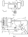
- the powertrain 1 comprises at least one driving motor 10, a gearbox 13, a controlled coupling device 11 and a control device 15 to coordinate them.
- the powertrain 1 is hybrid and is further equipped with a second driving motor 12 which is an electric traction machine mounted between the coupling device 11 and the gearbox 13 thus allowing an all-electric or hybrid driving mode in assistance of the driving motor 10.
- the driving motor 10 is an internal combustion heat engine comprising a linked drive shaft integral in rotation at the input of the coupling device.
- the controlled gearbox 13 comprises a connected primary shaft rotatably fixed at the output of the coupling device and can be configured to apply one or more gear ratios between the heat engine and the wheels 14 of the vehicle.
- the secondary shaft at the output of the gearbox 13 is linked in transmission to the wheels 24 of the vehicle.
- the electric traction machine is mounted on a set of wheels separate from that to which the heat engine is coupled. It is also contemplated to apply the control method for a powertrain having thermal traction only. In this case, the powertrain is not equipped with the electric traction machine 12.
- the coupling device 11 is able to selectively connect the drive shaft and the primary shaft in rotation as a function of a transmissible torque control for transmitting a motor torque to the wheels generated by the heat engine 10.
- the Coupling device 11 is a wet clutch disc device, which is actuated by hydraulic actuation means.
- the coupling device 11 can be controlled in a locked state, an open state and a sliding state, the latter state being used by the invention to increase the temperature of the lubricating fluid.
- the slip state corresponds to a state in which the disks responsible for transmitting the engine torque are in friction with each other. During a slip, only part of the engine torque is transmissible.
- the control of the slip state consists in controlling a transmissible torque which is less than the engine torque at the input of the coupling device 11.
- FIG 2 there is shown more precisely a block diagram of the wet clutch device 11 and the hydraulic actuation means.
- the clutch device 11 is connected at the input to the drive shaft 201 of the heat engine 10 and to the primary shaft 202 of the gearbox.
- the clutch device comprises, arranged alternately with respect to each other others, disks 204 and 205 secured respectively to the drive shaft 201 and to the primary shaft 202.
- a hydraulic piston 203 is movable in translation and can be actuated by the actuating means so as to join and disconnect in rotation the disks 204, 205 depending on the coupling command.
- the actuating means comprise an actuating interface 207 bringing an actuating fluid, such as oil, controlled in pressure or flow in an actuating chamber of the clutch device 11 in contact with the piston 203, a hydraulic actuation circuit 208 in which the actuating fluid circulates, a hydraulic distributor 210 controlled in current as a function of the coupling control, and a sensor for measuring the temperature 209 of the actuating fluid.
- the hydraulic distributor 210 is powered by a hydraulic pump 214 and its function is to regulate the pressure or the output flow in the actuation circuit 208.
- the hydraulic pump 214 also supplies via a bypass a lubrication circuit 212 of the clutch device 11.
- the lubrication circuit comprises a lubrication interface 211 to bring the actuating fluid into the friction zone of the discs 204, 205.
- the lubrication flow is controlled by a hydraulic distributor 213 controlled by current as a function of a lubrication control.
- the hydraulic distributor 213 is fed by the hydraulic pump 214 and there is provided a direct fluid return circuit to a reservoir 215, commonly called a tank.
- the fluid return circuit can be diverted to a device for cooling the fluid before returning to the reservoir 215.
- the hydraulic pump 214 draws the actuating fluid from the reservoir via a filter 206, commonly referred to as strainer.
- the hydraulic distributors 210, 213 are of the current-controlled solenoid valve type and are controlled by the control device 15. The control functions will be described more precisely in the remainder of the description.
- the pump hydraulic 214 supplies exclusively the actuation 208 and lubrication circuits 212.
- the thermal losses of the actuating fluid are reduced as it travels to the reservoir.
- control device 15 comprises one or more integrated circuit computers coupled to memories and intended to perform control functions for the powertrain operation.
- the memories record a control function containing the instructions for executing the control method according to the invention.
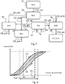
- a first interface module 31 calculates a torque setpoint of the driver's will CS_cvc from the cockpit control interface as a function of acceleration or braking parameters coming from the vehicle speed control devices. , such as a measurement of the position of an acceleration pedal or of a brake pedal by a proportional sensor, or of the depressing speed or of the depressing acceleration of the pedals.
- a second distribution module 32 calculates torque setpoints to be distributed between the torque actuators of the drive train, in particular an engine torque setpoint CS_mth intended for a control module 33 of the heat engine 10, a transmissible torque setpoint CS_emb to destination of a control module 35 of the clutch device 11 and an electric motor torque setpoint CS_mel intended for a control module 37 of the electric traction machine 12.
- the control module 33 of the thermal engine issues a command of engine torque CA_mth destined for motor 10.
- the control module 35 sends CA_act coupling commands to a control module 36 controlling the hydraulic distributor 210 and the hydraulic distributor 213.
- the pilot module 36 controls the distributors 210 , 213 according to the CA_act coupling commands to control by a control current a flow rate or a pressure of the actuating fluid in the cir actuator 208 and the lubrication circuit 212.
- the controlled pressure corresponds to a transmissible torque sought and operated by the clutch device 11.
- the control module 37 of the electric traction machine 12 receives an electric motor torque setpoint CS_mel coming from the distribution module 32 and generates an electric motor torque command CA_mel of the electric traction machine, in particular to transmit a torque to the wheels or generate braking torque.
- the control device 15 comprises a thermal regulation module 34 of the actuating fluid which is in charge of controlling the sliding state of the valve. clutch device 11 in order to increase the temperature of the actuating fluid Tcc when the latter is below a predetermined temperature threshold Ts.
- the thermal regulation module 34 is able to determine, on the one hand, the temperature Tcc of the actuating fluid in the actuation circuit 208, in particular from the sensor 209, and on the other hand the predetermined temperature threshold Ts of the actuation fluid.
- the temperature of the actuating fluid Tcc is determined from an estimate of the temperature calculated by software means based on the instantaneous transmission characteristics of the clutch device 11, for example according to the teaching of the patent document FR2883609A1 cited above in the state of the art.
- the thermal regulation module 34 calculates slip setpoints CS_gl1, CS_gl2, CS_gl3 intended respectively for the control module 33 of the heat engine 10, the control module 35 of the clutch device 11 and the control module 37 of the electric traction machine 12.
- the slip setpoints CS_gl1, CS_gl2 introduce a slip torque CP_gl and the setpoint CS_gl3 a slip compensation torque which can be of the same value as the slip torque CP_gl.
- the slip torque CP_gl is configured so that the transmissible torque command CA_act of the clutch device 11 becomes less than the engine torque command CA_mth at its input.
- the discs 204, 205 then enter a state of friction.
- the setpoint CS_gl1 controls a sliding torque that can be introduced by the heat engine 10 to bring the clutch device 11 into a sliding state. This sliding torque is added in addition to the engine torque setpoint CS_mth calculated by the distribution module 32.
- the setpoint CS_gl2 comprises at least one setpoint for controlling the flow rate of the fluid for actuating the lubrication circuit 212 so as to allow the return of the actuating fluid, which has been brought to the desired temperature during the slip state, to the reservoir 215 so that the latter is then brought to the actuation circuit 208 to improve the response accuracy dispenser 210.
- the setpoint CS_gl2 furthermore comprises a setpoint for actuating the actuation circuit 208 of the clutch device 11 in order to control a slip state when the slip is not caused by a change in the torque setpoint CS_mth.
- the setpoint CS_gl3 controls a compensation torque that can be introduced by the electric traction machine 12 to compensate for the loss of torque linked to the slip. This variant of the process will be described in the remainder of the description.
- the predetermined temperature threshold Ts depends on the type and size of the distributor 210. It is chosen, for example, at a temperature value of around 20 ° C. More generally, it is configured at a value for which a response from the distributor 210 to the transmissible torque setpoint CS_emb has a minimum level of dispersion, this value being indicated by the data supplied by the manufacturer of the distributor 210. It is known that the Dispersion in operation of a solenoid valve is attributable to the viscosity of the actuating fluid as well as to the expansion characteristics of its components. The control current causes a displacement of the solenoid valve core which creates a more or less important opening of the circuit. This opening has an opening section which can introduce pressure drops sensitive to the temperature of the actuating fluid.
- the figure 4 illustrates this dispersal effect.
- Two dispersion hystereses of the response of distributor 210 are shown as a function of the temperature of the actuating fluid supplied to it.
- On the abscissa is represented the control current of distributor 210 and the response in pressure or flow rate is ordered.
- the response curve C1 corresponds to a temperature of the actuating fluid lower than that of the curve C2.
- the linear operating range PL1 of curve C1 is smaller than the linear operating plate PL2 of curve C2.
- the widening of the linear operating range and of the valve piloting trip thresholds improves piloting precision.
- the invention makes it possible to bring the temperature of the fluid of the actuation circuit to a temperature for which the dispersion curve in response exhibits the lowest hysteresis.
- the figure 5 represents the control method according to the invention to improve the control precision of the actuation circuit
- the figures 6 and 7 represent the values of the drive train control setpoints during the execution of the method according to the invention.
- a first step 50 the vehicle is moving in a situation for which an engine torque is requested by the driver.
- the powertrain control method therefore controls at this step, a torque setpoint CS_cvc calculated from the driver's wishes, an engine torque setpoint CS_mth and an electric motor torque setpoint CS_mel, both in response to the CS_cvc setpoint , and a torque setpoint CS_emb transmissible by the clutch device 11 to allow transmission of the engine torque CS_mth to the wheels of the vehicle.
- the method comprises a step of verifying the capacity of the heat engine 10 and of the electric traction machine 12 to supply an additional torque to the engine torque setpoint CS_mth and to the engine torque setpoint CS_mel respectively. This is in order to introduce a slippage state of the clutch or to compensate for the slip state.
- the method further comprises determining a maximum engine torque CPmax that can be delivered by the heat engine 10 and the electric traction machine 12, and if the maximum engine torque CPmax is greater than the instantaneous engine torque CS_cvc which is delivered both by the heat engine 10 and by the electric traction machine 12, the increase in the engine torque setpoint CS_mth by the setpoint CS_gl1 is authorized, or the increase in the motor setpoint CS_mel by the setpoint CS_gl3 is authorized , according to which of the two engines is able to increase its load.
- the control method is then brought to step 52.
- step 57 which consists of maintaining the clutch device in a locked state or at least in a slip-free condition to avoid deteriorating drivability.
- step 52 the method then checks the temperature of the actuating fluid.
- the method comprises a step of temperature measurement by the sensor 209 positioned in the actuation circuit 208. The precision of the temperature measurement is thus improved.
- the temperature is determined by calculation according to a method described above.
- the method comprises a step of controlling the slip state according to the slip torque CP_gl to bring the temperature of the fluid d 'actuation above the temperature threshold. More specifically, an engine torque setpoint of at least one of the two driving motors of the power train 1, either of the heat engine 10 or of the electric traction machine 12, is increased by the value of the sliding torque. This situation is maintained as long as the temperature Tcc is below the threshold Ts.
- the value of the sliding torque CP_gl controlled by the method is a constant predetermined value. Nevertheless, it is conceivable that the sliding torque is a variable value, for example as a function of the temperature difference between the temperature of the actuating fluid Tcc and the temperature threshold Ts.
- a step 54 is provided for arbitration between the two possible modes for controlling the slip state, these modes being represented by steps 55, 56 on the figures 6 , 7 respectively.
- the arbitration is performed according to a priority criterion, favoring one of the two driving motors, and according to the capacity of each of the driving motors 10,12 of the powertrain 1 to provide an additional engine torque corresponding to the slip torque.
- the method comprises comparing the control of the motor torque CA_mth and a maximum torque Cmax10 that can be delivered by the heat engine 10, and when the control of the motor torque CA_mth is equal to the torque maximum Cmax10, the slip state is controlled according to the second mode 56, if not according to the first mode.
- the arbitration function is executed by the control module 34 of the thermal regulation.
- the slip state is caused by the increase in torque of the heat engine 10.
- the arbitration function has detected that the heat engine 10 has a maximum capacity Cmax10 which is greater than the instantaneous motor torque CA_mth.
- the control method controls the powertrain so that the transmissible torque command CA_act has a value lower than the engine torque command CA_mth.
- the setpoint CS_mth is increased by the value of the sliding torque CP_gl, and the command CA_act of the clutch device 11 is equal to the value of the setpoint CS_emb.
- the setpoint CS_emb is constant and has the same value as the setpoint CS_mth shown in dotted lines.
- the additional sliding torque CP_gl is therefore dissipated by the discs 204, 205 of the clutch device 11 and causes the temperature of the actuating fluid to rise.
- the lubrication circuit 212 is controlled by the circulation of fluid to bring the heated fluid to the reservoir 215.
- the temperature of the actuating fluid Tcc is below the threshold Ts, and the clutch device is in the locked state.
- the setpoint CS_mth is increased by the slip torque CP_gl as long as the temperature Tcc of the actuating fluid is below the threshold Ts. It will be noted that in this situation, the total engine torque CS_cvc to be transmitted to the wheels in response to the driver's wishes is only generated by the heat engine 10, the setpoint CS_mel is zero throughout this situation.
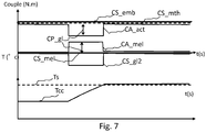
- the slip state is caused by a decrease in the transmissible torque command CA_act of the clutch device 11.
- the arbitration function has detected that the heat engine 10 is operating at its maximum capacity Cmax10 and the slip state is then controlled by a modification of the transmissible torque of the clutch device 11.
- step 56 the control method controls the powertrain so that the transmissible torque command CA_act has a value less than the first engine torque command CA_mth which is equal to the setpoint CS_mth shown in dotted lines.
- the transmissible torque setpoint CS_emb (which is equal to the value of the setpoint CS_mth) is reduced by the slip torque CP_gl according to the setpoint CS_gl2, and the electric motor torque setpoint CS_mel is increased by the value of the sliding torque CP_gl according to the setpoint CS_gl3 so as to compensate for the loss of torque resulting from the slip.
- the decrease in the transmissible torque CA_act causes a state of heat dissipation at the level of the disks. This results in a rise in temperature of the actuating fluid.
- the lubrication circuit 212 is controlled in the circulation of fluid to bring the heated fluid to the reservoir 215 and the sliding state is controlled as long as the temperature Tcc of the actuating fluid is below the threshold Ts.
- the sliding torque CP_gl can have a torque value different from the compensation torque of the electric machine.
- the state of locking of the clutch device it is common for the state of locking of the clutch device to be controlled by a transmissible torque command greater than the engine torque to be transmitted according to a predetermined torque difference in order to guarantee locking. This therefore results in a sliding torque value that must take this torque difference into account.
- the hydraulic pump 214 supplies another actuation circuit for example controlling a second device. 'clutch.
- this other actuation circuit is supplied with the actuation fluid used for lubricating the first clutch device and also benefits from the thermal regulation of the actuation fluid implemented by the invention.
- the method also applies to a thermal traction vehicle only.
- the slip state is controlled by the heat engine by controlling an engine torque greater than the torque transmissible by the clutch device, and the arbitration step 54 of the method is then not necessary.
- the method applies to an electric traction module in which the driving motor at the input of the coupling device is an electric traction machine.
- the coupling device may for example be a multi-plate clutch device, a clutch device with two friction plates or a wet clutch device.
Description
Le domaine de l'invention concerne un procédé de contrôle d'un groupe motopropulseur de véhicule automobile pour réguler la température du fluide d'actionnement d'un dispositif de couplage de la transmission, tel qu'un dispositif d'embrayage.The field of the invention relates to a method for controlling a motor vehicle powertrain in order to regulate the temperature of the actuating fluid of a transmission coupling device, such as a clutch device.
Conventionnellement, les véhicules automobiles à transmission pilotée, tel qu'un véhicule hybride, comportent un dispositif de couplage reliant un moteur thermique et une boite de vitesses et pouvant solidariser sélectivement en rotation l'arbre entrainant et l'arbre primaire de la boite de vitesses. Classiquement, la boite de vitesses et le dispositif de couplage sont pilotés hydrauliquement par un circuit hydraulique d'actionnement et un réseau de distributeurs alimentés par un fluide d'actionnement. Les distributeurs sont généralement des électrovannes pilotées en courant pour délivrer une pression/débit de fluide appliquant une force d'actionnement selon une position ou un couple transmissible recherché, comme cela est le cas pour un embrayage. De plus, dans le cas d'un dispositif de couplage de type embrayage humide à multidisques un circuit secondaire d'huile de lubrification est installé pour refroidir les disques de friction.Conventionally, motor vehicles with controlled transmission, such as a hybrid vehicle, include a coupling device connecting a heat engine and a gearbox and able to selectively join in rotation the driving shaft and the primary shaft of the gearbox. . Conventionally, the gearbox and the coupling device are controlled hydraulically by a hydraulic actuation circuit and a network of distributors supplied by an actuating fluid. The distributors are generally current-controlled solenoid valves to deliver a pressure / fluid flow rate applying an actuating force according to a position or a desired transmissible torque, as is the case for a clutch. In addition, in the case of a coupling device of the wet clutch type with multiple discs, a secondary lubricating oil circuit is installed to cool the friction discs.
Comme cela est bien connu, lorsqu'un embrayage fonctionne dans un état de glissement, de l'énergie thermique est dissipée et est transmise à l'huile de lubrification. Selon l'état de la technique, il est connu d'exploiter ce phénomène pour adapter le pilotage du couple transmissible. Le document
On connait en outre le document de brevet
Ces solutions traitent la problématique de la montée en température de l'huile de lubrification et de la variation du couple transmissible résultant de la montée en température de l'huile de lubrification. Il existe néanmoins un autre problème qui n'est pas abordé dans ses documents qui concerne la dispersion de réponse d'un circuit hydraulique d'actionnement. A basse température, on sait qu'un distributeur hydraulique présente une hystérésis de réponse détériorant la précision de pilotage. Il existe donc un besoin de traiter ce problème.These solutions deal with the problem of the rise in temperature of the lubricating oil and of the variation in the transmissible torque resulting from the rise in temperature of the lubricating oil. There is nevertheless another problem which is not addressed in its documents, which relates to the response dispersion of a hydraulic actuation circuit. At low temperature, it is known that a hydraulic distributor exhibits a response hysteresis which deteriorates the control precision. There is therefore a need to deal with this problem.
Plus précisément, l'invention concerne un procédé de contrôle d'un groupe motopropulseur d'un véhicule automobile pour réguler la température du fluide d'actionnement alimentant un distributeur hydraulique d'un circuit d'actionnement du groupe motopropulseur, le groupe motopropulseur comportant en outre un dispositif de couplage piloté par une consigne de couple transmissible, le dit dispositif de couplage étant relié à un circuit de lubrification alimenté par le fluide d'actionnement. Le procédé comporte une étape de détermination d'une température du fluide d'actionnement et le pilotage d'un état de glissement du dispositif de couplage de manière à modifier la température du fluide d'actionnement, et selon l'invention il comporte en outre la détermination d'un seuil de température prédéterminé du fluide d'actionnement et, lorsque la température du fluide d'actionnement est inférieure au seuil de température, le pilotage de l'état de glissement selon un couple de glissement pour amener la température du fluide d'actionnement au dessus du seuil de température.More specifically, the invention relates to a method of controlling a powertrain of a motor vehicle to regulate the temperature of the actuating fluid supplying a hydraulic distributor of an actuating circuit of the powertrain, the powertrain comprising in besides a coupling device controlled by a transmissible torque setpoint, said coupling device being connected to a lubrication circuit supplied by the actuating fluid. The method comprises a step of determining a temperature of the actuating fluid and controlling a sliding state of the coupling device so as to modify the temperature of the actuating fluid, and according to the invention it further comprises determining a predetermined temperature threshold of the actuating fluid and, when the temperature of the actuating fluid is below the temperature threshold, controlling the slip state according to a sliding torque to bring the temperature of the fluid actuation above the temperature threshold.
Plus précisément, le seuil de température prédéterminé est configuré à une valeur pour laquelle une réponse du distributeur présente un niveau de dispersion minimum.More specifically, the predetermined temperature threshold is configured at a value for which a response from the distributor has a minimum level of dispersion.
Selon une variante, la détermination de la température du fluide d'actionnement comporte une étape de mesure de température par un capteur de température du circuit d'actionnement.According to one variant, the determination of the temperature of the actuating fluid comprises a step of temperature measurement by a temperature sensor of the actuation circuit.
Selon une variante, la valeur du couple de glissement est une valeur prédéterminée constante.According to one variant, the value of the sliding torque is a constant predetermined value.
Selon une variante, le pilotage de l'état de glissement comporte une étape de pilotage d'au moins un moteur entrainant du groupe motopropulseur de manière que le couple transmissible du dispositif de couplage soit inférieur au couple moteur d'un premier moteur entrainant du groupe motopropulseur, le dit premier moteur entrainant étant relié en entrée du dispositif de couplage.According to one variant, the control of the slip state comprises a step of controlling at least one driving motor of the powertrain so that the transmissible torque of the coupling device is less than the engine torque of a first driving motor of the group. power unit, said first driving motor being connected to the input of the coupling device.
Selon une variante, il comporte en outre la détermination d'un couple moteur maximum pouvant être délivré par au moins le dit premier moteur entrainant, et si le couple moteur maximum est supérieur au couple moteur délivré par au moins le dit premier moteur entrainant, le pilotage de l'état de glissement est autorisé.According to a variant, it further comprises the determination of a maximum engine torque that can be delivered by at least said first driving motor, and if the maximum engine torque is greater than the engine torque delivered by at least said first driving motor, the control of the slip state is authorized.
Plus précisément, le pilotage de l'état de glissement est piloté selon un premier mode dans lequel le premier moteur entrainant introduit le couple de glissement de manière que le couple transmissible du dispositif de couplage soit inférieur au couple moteur dudit premier moteur entrainant.More precisely, the control of the slip state is controlled according to a first mode in which the first driving motor introduces the sliding torque so that the transmissible torque of the coupling device is less than the driving torque of said first driving motor.
Dans un mode de réalisation pour un véhicule hybride, le groupe motopropulseur comporte en outre un deuxième moteur entrainant apte à transmettre un couple moteur aux roues, et le procédé comporte en outre une étape d'arbitrage du pilotage de l'état de glissement entre le premier mode et un deuxième mode, et lorsque le pilotage de l'état de glissement est piloté selon le deuxième mode, le procédé comporte en outre la diminution du couple transmissible du dispositif de couplage selon le couple de glissement de manière que le couple transmissible du dispositif de couplage soit inférieur au couple moteur dudit premier moteur entrainant, et l'introduction du couple moteur par le deuxième moteur entrainant pour compenser la perte de couple résultant du glissement.In one embodiment for a hybrid vehicle, the powertrain further comprises a second driving motor capable of transmitting an engine torque to the wheels, and the method further comprises a step of arbitrating the control of the slip state between the first mode and a second mode, and when the control of the slip state is controlled according to the second mode, the method further comprises reducing the transmissible torque of the coupling device according to the sliding torque so that the transmissible torque of the coupling device is less than the driving torque of said first driving motor, and introducing the driving torque by the second motor driving to compensate for the loss of torque resulting from the slip.
Plus précisément, l'étape d'arbitrage comporte la comparaison du couple moteur dudit premier moteur entrainant et d'un couple maximum pouvant être délivré par le premier moteur entrainant, et lorsque le couple moteur est égal au couple maximum, l'état de glissement est piloté selon le deuxième mode.More precisely, the arbitration step comprises the comparison of the driving torque of said first driving motor and of a maximum torque that can be delivered by the first driving motor, and when the driving torque is equal to the maximum torque, the slip state is controlled according to the second mode.
Il est prévu selon l'invention, un véhicule automobile comportant un groupe motopropulseur piloté par un dispositif de contrôle, et dans lequel le dispositif de contrôle exécute le procédé selon l'un quelconque des modes de réalisation précédent.According to the invention, there is provided a motor vehicle comprising a powertrain controlled by a control device, and in which the control device executes the method according to any one of the preceding embodiments.
Grâce à l'invention, les effets d'une dissipation thermique provoquée par un état de glissement d'un dispositif de couplage sont mis à profit pour chauffer le fluide d'actionnement d'un distributeur hydraulique d'un circuit d'actionnement relié au circuit de lubrification. On améliore ainsi la précision de contrôle des distributeurs hydrauliques et la précision du pilotage d'un dispositif actionné hydrauliquement.Thanks to the invention, the effects of heat dissipation caused by a sliding state of a coupling device are used to heat the actuating fluid of a hydraulic distributor of an actuation circuit connected to the lubrication circuit. This improves the control precision of the hydraulic distributors and the control precision of a hydraulically actuated device.
D'autres caractéristiques et avantages de la présente invention apparaîtront plus clairement à la lecture de la description détaillée qui suit comprenant des modes de réalisation de l'invention donnés à titre d'exemples nullement limitatifs et illustrés par les dessins annexés, dans lesquels :
- la
figure 1 représente un groupe motopropulseur de véhicule automobile dans lequel est mis en œuvre le procédé de contrôle selon l'invention ; - la
figure 2 représente un schéma de principe du dispositif de couplage, son circuit d'actionnement hydraulique et son circuit de lubrification; - la
figure 3 représente une partie des modules de pilotage du dispositif de contrôle du groupe motopropulseur intervenant dans la mise en œuvre de l'invention ; - la
figure 4 représente un graphique illustrant les dispersions de fonctionnement du distributeur hydraulique en fonction de la température du fluide d'actionnement ; - la
figure 5 représente une séquence du procédé de contrôle selon l'invention ; - la
figure 6 représente les valeurs des consignes de pilotage du groupe motopropulseur durant l'exécution du procédé selon l'invention lors d'un premier mode de pilotage ; - la
figure 7 représente les valeurs des consignes de pilotage du groupe motopropulseur durant l'exécution du procédé selon l'invention lors d'un deuxième mode de pilotage.
- the
figure 1 represents a motor vehicle powertrain in which the control method according to the invention is implemented; - the
figure 2 represents a block diagram of the coupling device, its hydraulic actuation circuit and its lubrication circuit; - the
figure 3 represents part of the control modules of the powertrain control device involved in the implementation of the invention; - the
figure 4 represents a graph illustrating the operating dispersions of the hydraulic distributor as a function of the temperature of the actuating fluid; - the
figure 5 represents a sequence of the control method according to the invention; - the
figure 6 represents the values of the drive train control setpoints during the execution of the method according to the invention during a first control mode; - the
figure 7 represents the values of the drive train control setpoints during the execution of the method according to the invention during a second control mode.
L'invention s'applique aux véhicules automobiles dans lesquels, comme cela est représenté en
Dans une variante, la machine électrique de traction est montée sur un train de roues distinct de celui sur lequel est attelé le moteur thermique. On envisage également d'appliquer le procédé de contrôle pour groupe motopropulseur possédant une traction thermique uniquement. Dans ce cas, le groupe motopropulseur n'est pas équipé de la machine électrique de traction 12.In a variant, the electric traction machine is mounted on a set of wheels separate from that to which the heat engine is coupled. It is also contemplated to apply the control method for a powertrain having thermal traction only. In this case, the powertrain is not equipped with the
Le dispositif de couplage 11 est apte à solidariser sélectivement en rotation l'arbre d'entrainement et l'arbre primaire en fonction d'une commande de couple transmissible pour transmettre un couple moteur aux roues généré par le moteur thermique 10. Par exemple, le dispositif de couplage 11 est un dispositif d'embrayage humide à disques, lequel est actionné par des moyens d'actionnement hydraulique.The
Le dispositif de couplage 11 est pilotable dans un état de verrouillage, un état d'ouverture et un état de glissement, ce dernier état est utilisé par l'invention pour augmenter la température du fluide de lubrification. L'état de glissement correspond à un état pour lequel les disques en charge de transmettre le couple moteur sont en friction les uns avec les autres. Lors d'un glissement, seule une partie du couple moteur est transmissible. Le pilotage de l'état de glissement consiste à commander un couple transmissible qui est inférieur au couple moteur en entrée du dispositif de couplage 11.The
En
Les moyens d'actionnement comportent une interface d'actionnement 207 amenant un fluide d'actionnement, tel que de l'huile, piloté en pression ou débit dans une chambre d'actionnement du dispositif d'embrayage 11 en contact avec le piston 203, un circuit d'actionnement hydraulique 208 dans lequel circule le fluide d'actionnement, un distributeur hydraulique 210 piloté en courant en fonction de la commande de couplage, et un capteur de mesure de la température 209 du fluide d'actionnement. Le distributeur hydraulique 210 est alimenté par une pompe hydraulique 214 et sa fonction est de réguler la pression ou le débit de sortie dans le circuit d'actionnement 208.The actuating means comprise an actuating interface 207 bringing an actuating fluid, such as oil, controlled in pressure or flow in an actuating chamber of the
Par ailleurs, la pompe hydraulique 214 alimente également via une dérivation un circuit de lubrification 212 du dispositif d'embrayage 11. Le circuit de lubrification comporte une interface de lubrification 211 pour amener le fluide d'actionnement dans la zone de friction des disques 204, 205. Le débit de lubrification est piloté par un distributeur hydraulique 213 piloté en courant en fonction d'une commande de lubrification. Le distributeur hydraulique 213 est alimenté par la pompe hydraulique 214 et il est prévu un circuit de retour de fluide direct vers un réservoir 215, couramment appelé bâche. Toutefois, il est également envisageable que le circuit de retour de fluide puisse être dérivé vers un dispositif de refroidissement du fluide avant de revenir au réservoir 215. La pompe hydraulique 214 puise le fluide d'actionnement dans le réservoir via un filtre 206, couramment appelé crépine. Les distributeurs hydrauliques 210, 213 sont de type électrovanne à commande de courant et sont pilotés par le dispositif de contrôle 15. Les fonctions de pilotage seront décrites plus précisément dans la suite de la description.Furthermore, the hydraulic pump 214 also supplies via a bypass a lubrication circuit 212 of the
De préférence, afin d'améliorer le contrôle et la précision du circuit d'actionnement de l'embrayage 11, il est envisagé de réduire au plus court la longueur des circuits d'actionnement 208 et de lubrification 212. A cet effet, la pompe hydraulique 214 alimente exclusivement les circuits d'actionnement 208 et de lubrification 212. Ainsi, lors de la régulation de température du fluide d'actionnement au moyen du dispositif d'embrayage 11 par un état de glissement, les pertes thermiques du fluide d'actionnement sont réduites lorsqu'il circule jusqu'au réservoir.Preferably, in order to improve the control and the precision of the actuation circuit of the clutch 11, it is envisaged to reduce the length of the actuation circuits 208 and of the lubrication 212. To this end, the pump hydraulic 214 supplies exclusively the actuation 208 and lubrication circuits 212. Thus, when the temperature of the actuating fluid is regulated by means of the
En
Un premier module d'interface 31 calcule une consigne de couple de la volonté du conducteur CS_cvc à partir de l'interface de pilotage de l'habitacle en fonction de paramètres d'accélération ou de freinage provenant des dispositifs de commande de la vitesse du véhicule, tels qu'une mesure de la position d'une pédale d'accélération ou d'une pédale de freinage par un capteur proportionnel, ou bien de la vitesse d'enfoncement ou de l'accélération d'enfoncement des pédales. Un deuxième module de répartition 32 calcule des consignes de couple à répartir entre les actionneurs en couple du groupe motopropulseur, notamment une consigne de couple moteur CS_mth à destination d'un module de pilotage 33 du moteur thermique 10, une consigne de couple transmissible CS_emb à destination d'un module de pilotage 35 du dispositif d'embrayage 11 et une consigne de couple moteur électrique CS_mel à destination d'un module de pilotage 37 de la machine électrique de traction 12. Le module de pilotage 33 du moteur thermique émet une commande de couple moteur CA_mth à destination du moteur 10. Le module de pilotage 35 émet des commandes de couplage CA_act à destination d'un module de pilotage 36 pilotant le distributeur hydraulique 210 et le distributeur hydraulique 213. Le module de pilotage 36 contrôle les distributeurs 210, 213 en fonction des commandes de couplage CA_act pour piloter par un courant de commande un débit ou une pression du fluide d'actionnement dans le circuit d'actionnement 208 et le circuit de lubrification 212. Dans le cas du pilotage du distributeur 210, la pression pilotée correspond à un couple transmissible recherché et opéré par le dispositif d'embrayage 11. Dans le cas du pilotage du distributeur 213, la pression pilotée correspond à un débit de lubrification. Enfin, le module de pilotage 37 de la machine électrique de traction 12 reçoit une consigne de couple moteur électrique CS_mel issue du module de répartition 32 et élabore une commande de couple moteur électrique CA_mel de la machine électrique de traction, notamment pour transmettre un couple aux roues ou générer un couple de freinage.A
Par ailleurs, à la base de l'invention, pour améliorer la précision du pilotage du distributeur 210, le dispositif de contrôle 15 comporte un module de régulation thermique 34 du fluide d'actionnement qui est en charge de piloter l'état de glissement du dispositif d'embrayage 11 afin d'augmenter la température du fluide d'actionnement Tcc lorsque cette dernière est inférieure à un seuil de température prédéterminé Ts. Le module de régulation thermique 34 est apte à déterminer d'une part, la température Tcc du fluide d'actionnement dans le circuit d'actionnement 208, notamment à partir du capteur 209, et d'autre part le seuil de température prédéterminé Ts du fluide d'actionnement.Furthermore, at the basis of the invention, to improve the precision of the control of the distributor 210, the
Dans une variante, à partir de méthodes bien connues de l'homme du métier, la température du fluide d'actionnement Tcc est déterminée à partir d'une estimation de la température calculée par des moyens logiciels se basant sur les caractéristiques instantanées de transmission du dispositif d'embrayage 11, par exemple selon les enseignement du document brevet
De plus, le module de régulation thermique 34 calcule des consignes de glissement CS_gl1, CS_gl2, CS_gl3 à destination respectivement du module de pilotage 33 du moteur thermique 10, du module de pilotage 35 du dispositif d'embrayage 11 et du module de pilotage 37 de la machine électrique de traction 12. Les consignes de glissement CS_gl1, CS_gl2, introduisent un couple de glissement CP_gl et la consigne CS_gl3 un couple de compensation du glissement pouvant être de même valeur que le couple de glissement CP_gl. Le couple de glissement CP_gl est configuré pour que la commande de couple transmissible CA_act du dispositif d'embrayage 11 devienne inférieure à la commande de couple moteur CA_mth à son entrée. Les disques 204, 205 entrent alors en état de friction.In addition, the
La consigne CS_gl1 commande un couple de glissement pouvant être introduit par le moteur thermique 10 pour amener le dispositif d'embrayage 11 dans un état de glissement. Ce couple de glissement est ajouté en complément de la consigne de couple moteur CS_mth calculée par le module de répartition 32. La consigne CS_gl2 comporte au moins une consigne de pilotage du débit de circulation du fluide d'actionnement du circuit de lubrification 212 de manière à permettre le retour du fluide d'actionnement, qui a été amené à la température voulue lors de l'état de glissement, vers le réservoir 215 afin que celui-ci soit ensuite amené vers le circuit d'actionnement 208 pour améliorer la précision de réponse du distributeur 210.The setpoint CS_gl1 controls a sliding torque that can be introduced by the
Par ailleurs, il est envisagé que la consigne CS_gl2 comporte en outre une consigne d'actionnement du circuit d'actionnement 208 du dispositif d'embrayage 11 afin de piloter un état de glissement lorsque le glissement n'est pas provoqué par un changement de la consigne de couple moteur CS_mth. Dans cette situation, la consigne CS_gl3 commande un couple de compensation pouvant être introduit par la machine électrique de traction 12 pour compenser la perte de couple lié au glissement. On décrira cette variante du procédé dans la suite de la description.Furthermore, it is envisaged that the setpoint CS_gl2 furthermore comprises a setpoint for actuating the actuation circuit 208 of the
Le seuil de température prédéterminé Ts dépend du type et du dimensionnement du distributeur 210. Il est choisi par exemple à une valeur de température d'environ 20°c. Plus généralement, il est configuré à une valeur pour laquelle une réponse du distributeur 210 à la consigne de couple transmissible CS_emb présente un niveau de dispersion minimum, cette valeur étant indiquée par les données fournies par le constructeur du distributeur 210. Il est connu que la dispersion de fonctionnement d'une électrovanne est imputable à la viscosité du fluide d'actionnement ainsi qu'aux caractéristiques de dilation de ses composants. Le courant de commande provoque un déplacement du noyau de l'électrovanne qui créé une ouverture plus ou moins importante du circuit. Cette ouverture présente une section d'ouverture qui peut introduire des pertes de charges sensibles à la température du fluide d'actionnement.The predetermined temperature threshold Ts depends on the type and size of the distributor 210. It is chosen, for example, at a temperature value of around 20 ° C. More generally, it is configured at a value for which a response from the distributor 210 to the transmissible torque setpoint CS_emb has a minimum level of dispersion, this value being indicated by the data supplied by the manufacturer of the distributor 210. It is known that the Dispersion in operation of a solenoid valve is attributable to the viscosity of the actuating fluid as well as to the expansion characteristics of its components. The control current causes a displacement of the solenoid valve core which creates a more or less important opening of the circuit. This opening has an opening section which can introduce pressure drops sensitive to the temperature of the actuating fluid.
La
La
A une étape 51, le procédé comporte une étape de vérification de la capacité du moteur thermique 10 et de la machine électrique de traction 12 à fournir un couple additionnel à la consigne de couple moteur CS_mth et à la consigne de couple moteur CS_mel respectivement. Ceci afin d'introduire un état de glissement de l'embrayage ou de compenser l'état de glissement. A cet effet, le procédé comporte en outre la détermination d'un couple moteur maximum CPmax pouvant être délivré par le moteur thermique 10 et la machine électrique de traction 12, et si le couple moteur maximum CPmax est supérieur au couple moteur instantané CS_cvc qui est délivré à la fois par le moteur thermique 10 et par la machine électrique de traction 12, l'augmentation de la consigne de couple moteur CS_mth par la consigne CS_gl1 est autorisée, ou l'augmentation de la consigne moteur CS_mel par la consigne CS_gl3 est autorisée, selon lequel des deux moteurs est en capacité d'augmenter sa charge. Le procédé de contrôle est ensuite amené alors à l'étape 52.In a
Dans la situation pour laquelle le groupe motopropulseur 1 n'est pas en capacité d'augmenter sa charge moteur alors le procédé est amené à l'étape 57 qui consiste à maintenir le dispositif d'embrayage dans un état de verrouillage ou du moins dans un état sans glissement pour éviter de détériorer l'agrément de conduite.In the situation for which the
A l'étape 52, le procédé vérifie ensuite la température du fluide d'actionnement. A cet effet, pour déterminer la température du fluide d'actionnement Tcc le procédé comporte une étape de mesure de température par le capteur 209 positionné dans le circuit d'actionnement 208. On améliore ainsi la précision de la mesure de température. Toutefois, dans une variante la température est déterminée par calcul selon une méthode décrite précédemment.In
Ensuite, à une étape 53, lorsque la température du fluide d'actionnement Tcc est inférieure au seuil de température Ts, le procédé comporte une étape de pilotage de l'état de glissement selon le couple de glissement CP_gl pour amener la température du fluide d'actionnement au dessus du seuil de température. Plus précisément, une consigne de couple moteur d'au moins un des deux moteurs entrainants du groupe motopropulseur 1, soit du moteur thermique 10, soit de la machine électrique de traction 12, est augmentée de la valeur du couple de glissement. Cette situation est maintenue tant que la température Tcc est inférieure au seuil Ts. La valeur du couple de glissement CP_gl pilotée par le procédé est une valeur prédéterminée constante. Néanmoins, il est envisageable que le couple de glissement soit une valeur variable, par exemple en fonction de l'écart de température entre la température du fluide d'actionnement Tcc et le seuil de température Ts.Then, in a
A cet effet, il est prévu une étape d'arbitrage 54 entre les deux modes possibles pour le pilotage de l'état de glissement, ces modes étant représentés par les étapes 55, 56 sur les
Lors de l'étape d'arbitrage 54, le procédé comporte la comparaison de la commande du couple moteur CA_mth et d'un couple maximum Cmax10 pouvant être délivré par le moteur thermique 10, et lorsque la commande du couple moteur CA_mth est égale au couple maximum Cmax10, l'état de glissement est piloté selon le deuxième mode 56, sinon selon le premier mode. La fonction d'arbitrage est exécutée par le module de pilotage 34 de la régulation thermique.During the
Dans une variante, il est prévu que le procédé exécute seulement l'un des deux modes de pilotage de l'état de glissement.In one variant, provision is made for the method to execute only one of the two modes of controlling the slip state.
Selon le premier mode, illustré par la
Donc, à une étape 55, le procédé de contrôle pilote le groupe motopropulseur de manière que la commande de couple transmissible CA_act ait une valeur inférieure à la commande de couple moteur CA_mth. Ici, la consigne CS_mth est augmentée de la valeur du couple de glissement CP_gl, et la commande CA_act du dispositif d'embrayage 11 est égale à la valeur de la consigne CS_emb. On notera que la consigne CS_emb est constante et est de même valeur que la consigne CS_mth représentée en trait en pointillé. Ainsi, la commande du moteur thermique résultante CA_mth est égale à : CA_mth = CS_mth + CP_gl, CP_gl étant introduit par la consigne CS_gl1. Le couple de glissement supplémentaire CP_gl est donc dissipé par les disques 204, 205 du dispositif d'embrayage 11 et provoque une montée en température du fluide d'actionnement. Le circuit de lubrification 212 est piloté en circulation de fluide pour amener le fluide chauffé au réservoir 215.Therefore, in a
Comme on le voit en
Selon le deuxième mode, illustré par la
Ensuite, à l'étape 56, le procédé de contrôle pilote le groupe motopropulseur de manière que la commande de couple transmissible CA_act ait une valeur inférieure à la première commande de couple moteur CA_mth qui est égale à la consigne CS_mth représentée en trait en pointillé. Ici, la consigne de couple transmissible CS_emb (qui est égale à la valeur de la consigne CS_mth) est diminuée du couple de glissement CP_gl selon la consigne CS_gl2, et la consigne de couple moteur électrique CS_mel est augmentée de la valeur du couple de glissement CP_gl selon la consigne CS_gl3 de manière à compenser la perte de couple résultant du glissement.Then, in
Donc, comme on le voit en
Dans les
On a décrit précédemment un mode de réalisation pour lequel le circuit d'actionnement 208 pilote le dispositif d'embrayage 11. Dans d'autres modes de réalisation, la pompe hydraulique 214 alimente un autre circuit d'actionnement pilotant par exemple un deuxième dispositif d'embrayage. Ainsi, cet autre circuit d'actionnement est alimenté par le fluide d'actionnement utilisé pour la lubrification du premier dispositif d'embrayage et bénéficie également de la régulation thermique du fluide d'actionnement mise en œuvre par l'invention.An embodiment has previously been described for which the actuation circuit 208 controls the
Le procédé s'applique également pour un véhicule à traction thermique uniquement. Dans ce cas, l'état de glissement est piloté par le moteur thermique en pilotant un couple moteur supérieur au couple transmissible par le dispositif d'embrayage, et l'étape d'arbitrage 54 du procédé n'est alors pas nécessaire. Dans une variante, le procédé s'applique pour un module de traction électrique dans lequel le moteur entrainant en entrée du dispositif de couplage est une machine électrique de traction. Par ailleurs, le dispositif de couplage peut être par exemple un dispositif d'embrayage multidisques, un dispositif d'embrayage à deux plateaux de friction ou un dispositif de crabotage humide.The method also applies to a thermal traction vehicle only. In this case, the slip state is controlled by the heat engine by controlling an engine torque greater than the torque transmissible by the clutch device, and the
Claims (10)
- Method of controlling a powertrain (1) of a motor vehicle to regulate the temperature of the actuating fluid supplying a hydraulic distributor (210) of an actuating circuit (208) of the powertrain , the powertrain comprising furthermore a coupling device (11) controlled by a transmissible
torque setpoint (CS_emb), said coupling device (11) being connected to a lubrication circuit (212) powered by the actuating fluid, said method comprising a step of determination (52) of te mperature (Tcc) of the actuating fluid and controlling a slip state (53) of the coupling device (11) so as to modify the temperature of the actuating fluid, characterized in that it further comprises determining a predetermined temperature threshold (Ts) of the actuating fluid and, when the temperature of the actuating fluid (Tcc) is below the temperature threshold (Ts), the control of e the sliding state (53) according to a sliding torque (CP_gl) to bring the temperature of the actuating fluid above the temperature threshold (Ts). - Method according to claim 1, characterized in that the predetermined temperature threshold (Ts) is configured at a value for which a distributor response (210) has a minimum level of dispersion.
- Method according to claim 1 or 2, characterized in that the determination of the temperature (52) of the actuating fluid comprises a step of measuring the temperature by a temperature sensor (209) of the actuating circuit (208).
- Method according to any one of claims 1 to 3, characterized in that the value of the sliding torque (CP_gl) is a constant predetermined value.
- Method according to any one of claims 1 to 4, characterized in that e the control of the slip state (53) comprises a control step (55 ; 56) so that the transmittable torque (CA_act) of the device coupling (11) is less than the torque motor (CA_mth) of a first motor driving (10) the group powerplant, the first motor driving said (10) being connected at the input of the coupling device (11).
- Method according to claim 5, characterized in that it further comprises the determination of a maximum engine torque (CPmax) being issued by at least the said first motor leading (10) and if the maximum engine torque (CPmax) is greater than the motor torque delivered by at least the said first motor driving (10), the control of the slip state (53) is allowed.
- Method according to any one of claims 5 to 6, characterized in that the control of the sliding state (53) is controlled according to a first mode (55) in which the first driving motor (10) introduces the sliding torque (CP_gl) so that the transmissible torque (CA_act) of the coupling device (11) is less than the motor torque (CA_mth) of said first driving motor (10).
- Method according to claim 7 , powertrain comport ant further a second motor driving (12) adapted to transmit an engine torque (CA_mel) to the wheels , characterized in that it further comprises a step of arbitration (54) control of the slip state (53) between the first mode (55) and a second mode (56), and when the control of the slip state (53) is controlled according to the second mode (56), the method further comprises the reduction of the transmissible torque of the coupling device (11) according to the sliding torque (CP_gl) of such that the transmittable torque (CA_act) of the coupling device (11) is less than the torque motor (CA_mth) of said first
motor leading (10) and the introduction of u torque (CA_mel) by the second motor leading (12) to compensate for the loss of torque resulting from the sliding. - Method of claim 8, characterized in that the arbitration step (54) comprises the comparison of the engine torque (CA_mth) of said
first driving motor (10) and a maximum torque (Cmax10) that can be delivered by the First r engine leading (10) and when the engine torque (CA_mth) is equal to the maximum torque (Cmax10), the slip state is controlled according to the second guide (56). - Motor vehicle comprising a powertrain (1) controlled by a control device, characterized in that the control device executes the method according to any one of claims 1 to 9.
Applications Claiming Priority (2)
| Application Number | Priority Date | Filing Date | Title |
|---|---|---|---|
| FR1754229A FR3066242B1 (en) | 2017-05-15 | 2017-05-15 | METHOD FOR CONTROLLING A MOTORPROOF GROUP FOR THERMAL CONTROL OF A HYDRAULIC CIRCUIT |
| PCT/FR2018/050948 WO2018211189A1 (en) | 2017-05-15 | 2018-04-16 | Method for controlling a power train for thermal regulation of a hydraulic circuit |
Publications (2)
| Publication Number | Publication Date |
|---|---|
| EP3625472A1 EP3625472A1 (en) | 2020-03-25 |
| EP3625472B1 true EP3625472B1 (en) | 2021-01-20 |
Family
ID=59153172
Family Applications (1)
| Application Number | Title | Priority Date | Filing Date |
|---|---|---|---|
| EP18719979.9A Active EP3625472B1 (en) | 2017-05-15 | 2018-04-16 | Method for controlling a power train for thermal regulation of a hydraulic circuit |
Country Status (4)
| Country | Link |
|---|---|
| EP (1) | EP3625472B1 (en) |
| CN (1) | CN110651131B (en) |
| FR (1) | FR3066242B1 (en) |
| WO (1) | WO2018211189A1 (en) |
Family Cites Families (19)
| Publication number | Priority date | Publication date | Assignee | Title |
|---|---|---|---|---|
| DE10045758A1 (en) | 2000-09-15 | 2002-03-28 | Bosch Gmbh Robert | Method and device for operating a clutch |
| JP3744414B2 (en) * | 2001-11-29 | 2006-02-08 | トヨタ自動車株式会社 | Vehicle control device |
| US6715597B1 (en) * | 2002-10-25 | 2004-04-06 | Borgwarner, Inc. | Dual clutch transmission clutch cooling control method |
| FR2883609B1 (en) | 2005-03-25 | 2007-06-01 | Renault Sas | METHOD FOR CONTROLLING THE SLIDING OF A WET CLUTCH SYSTEM |
| JP2007126040A (en) * | 2005-11-04 | 2007-05-24 | Toyota Motor Corp | Control device of vehicle |
| US8079933B2 (en) * | 2007-11-04 | 2011-12-20 | GM Global Technology Operations LLC | Method and apparatus to control engine torque to peak main pressure for a hybrid powertrain system |
| FR2933913B1 (en) | 2008-07-16 | 2011-01-14 | Renault Sas | CONTROL DEVICE ADAPTIVE TO THE EVOLUTION OF THE CHARACTERISTIC OF A CLUTCH BASED ON THE TEMPERATURE APPLIED TO A VEHICLE EQUIPPED WITH A 4X4 PILOT SYSTEM. |
| JP5402060B2 (en) * | 2009-02-17 | 2014-01-29 | 日産自動車株式会社 | Control device for electric vehicle |
| US8155850B2 (en) * | 2009-07-23 | 2012-04-10 | GM Global Technology Operations LLC | System for controlling peak torque in manual transmissions |
| JP4913848B2 (en) * | 2009-07-28 | 2012-04-11 | 本田技研工業株式会社 | Control device for automatic transmission |
| FR2965779B1 (en) * | 2010-10-11 | 2013-06-14 | Peugeot Citroen Automobiles Sa | METHOD FOR CONTROLLING A STARTING OF A VEHICLE EQUIPPED WITH A SYSTEM FOR STARTING UP AN ENGINE |
| US8731793B2 (en) * | 2010-12-29 | 2014-05-20 | Caterpillar Inc. | Clutch temperature estimation for a mobile machine |
| US8915076B2 (en) * | 2011-01-12 | 2014-12-23 | Gm Global Technology Operations, Llc | Transmission hydraulic control system having flow augmentation |
| US8855876B2 (en) * | 2011-07-21 | 2014-10-07 | Honda Motor Co., Ltd. | System and method for managing an operating temperature of a working fluid in a vehicle powertrain |
| JP6111077B2 (en) * | 2013-01-17 | 2017-04-05 | 株式会社エフ・シー・シー | Power transmission device |
| DE102014225657A1 (en) * | 2014-12-12 | 2016-06-16 | Schaeffler Technologies AG & Co. KG | Method for controlling a cooling of a clutch for a motor vehicle |
| JP2016222151A (en) * | 2015-06-01 | 2016-12-28 | アイシン精機株式会社 | Clutch characteristic learning device |
| US20160041066A1 (en) * | 2015-10-23 | 2016-02-11 | Caterpillar Inc. | Method for monitoring temperature of clutch assembly |
| CN106347372B (en) * | 2016-11-15 | 2018-11-02 | 安徽江淮汽车集团股份有限公司 | A kind of semi-linkage point determines method and system |
-
2017
- 2017-05-15 FR FR1754229A patent/FR3066242B1/en not_active Expired - Fee Related
-
2018
- 2018-04-16 CN CN201880032024.1A patent/CN110651131B/en active Active
- 2018-04-16 WO PCT/FR2018/050948 patent/WO2018211189A1/en unknown
- 2018-04-16 EP EP18719979.9A patent/EP3625472B1/en active Active
Non-Patent Citations (1)
| Title |
|---|
| None * |
Also Published As
| Publication number | Publication date |
|---|---|
| WO2018211189A1 (en) | 2018-11-22 |
| CN110651131B (en) | 2021-04-27 |
| FR3066242A1 (en) | 2018-11-16 |
| EP3625472A1 (en) | 2020-03-25 |
| CN110651131A (en) | 2020-01-03 |
| FR3066242B1 (en) | 2019-06-14 |
Similar Documents
| Publication | Publication Date | Title |
|---|---|---|
| JP3511958B2 (en) | Hybrid vehicle clutch control device | |
| KR102448975B1 (en) | Deceleration based brake coolant system and method thereof | |
| US8262539B2 (en) | Power transmitting apparatus | |
| FR3005021A1 (en) | SYSTEM AND METHOD FOR CONTROLLING A MOTOR VEHICLE IN FREEWHEEL ROLLING | |
| CN109890674B (en) | Method for controlling motor of vehicle | |
| JP5085822B2 (en) | Method and apparatus for clutch actuation | |
| SE1250320A1 (en) | Procedure and system for controlling a motor speed widened vehicle | |
| US6322477B1 (en) | Method of and apparatus for influencing the shifting of transmissions in the power trains of motor vehicles | |
| EP3625472B1 (en) | Method for controlling a power train for thermal regulation of a hydraulic circuit | |
| US9670857B2 (en) | Torque control of a power-plant for launching a vehicle with a manual transmission | |
| CN108779817B (en) | Method for adapting the engagement point of a separating clutch of a vehicle | |
| EP3615829B1 (en) | Method for controlling a power train of a motor vehicle to prevent the stalling of an engine | |
| EP1505309A2 (en) | Control method for a drive unit including automated transmission and clutch | |
| US10760628B2 (en) | Clutch control device | |
| RU2269709C1 (en) | Clashless gearshift system | |
| KR102472609B1 (en) | Method for reducing, if required, a drag torque of a friction clutch | |
| FR3103440A1 (en) | PROCESS FOR DETERMINING THE TORQUE TRANSMITTED BY THE ENGINE TO THE DRIVE CHAIN | |
| EP3652458B1 (en) | Method for controlling a propulsion unit to prevent loop stalling during vehicle pull-away (launch) | |
| US10851855B2 (en) | Clutch control device | |
| JP5240062B2 (en) | Coasting control device | |
| SE542258C2 (en) | A method for clutch torque adaptation, a control unit for clutch torque adaptation, a vehicle comprising such a control unit, a computer program and a computer-readable medium | |
| FR2947768A1 (en) | Actuator i.e. clutch, managing method for four-wheel drive motor vehicle, involves measuring torque transmitted by actuator, and determining current to be transmitted to actuator from difference between measured torque and torque setpoint | |
| FR3106320A1 (en) | Method of controlling a motor vehicle to avoid jolting the clutch | |
| EP1429011A1 (en) | Engine torque control method and system for an automotive vehicle | |
| CN116249844A (en) | Method for controlling a coupling system of a mechanical transmission |
Legal Events
| Date | Code | Title | Description |
|---|---|---|---|
| STAA | Information on the status of an ep patent application or granted ep patent |
Free format text: STATUS: UNKNOWN |
|
| STAA | Information on the status of an ep patent application or granted ep patent |
Free format text: STATUS: THE INTERNATIONAL PUBLICATION HAS BEEN MADE |
|
| PUAI | Public reference made under article 153(3) epc to a published international application that has entered the european phase |
Free format text: ORIGINAL CODE: 0009012 |
|
| STAA | Information on the status of an ep patent application or granted ep patent |
Free format text: STATUS: REQUEST FOR EXAMINATION WAS MADE |
|
| 17P | Request for examination filed |
Effective date: 20191017 |
|
| AK | Designated contracting states |
Kind code of ref document: A1 Designated state(s): AL AT BE BG CH CY CZ DE DK EE ES FI FR GB GR HR HU IE IS IT LI LT LU LV MC MK MT NL NO PL PT RO RS SE SI SK SM TR |
|
| AX | Request for extension of the european patent |
Extension state: BA ME |
|
| DAX | Request for extension of the european patent (deleted) | ||
| RAV | Requested validation state of the european patent: fee paid |
Extension state: MA Effective date: 20191017 |
|
| GRAP | Despatch of communication of intention to grant a patent |
Free format text: ORIGINAL CODE: EPIDOSNIGR1 |
|
| STAA | Information on the status of an ep patent application or granted ep patent |
Free format text: STATUS: GRANT OF PATENT IS INTENDED |
|
| INTG | Intention to grant announced |
Effective date: 20200923 |
|
| RAP1 | Party data changed (applicant data changed or rights of an application transferred) |
Owner name: PSA AUTOMOBILES SA |
|
| GRAS | Grant fee paid |
Free format text: ORIGINAL CODE: EPIDOSNIGR3 |
|
| GRAA | (expected) grant |
Free format text: ORIGINAL CODE: 0009210 |
|
| STAA | Information on the status of an ep patent application or granted ep patent |
Free format text: STATUS: THE PATENT HAS BEEN GRANTED |
|
| AK | Designated contracting states |
Kind code of ref document: B1 Designated state(s): AL AT BE BG CH CY CZ DE DK EE ES FI FR GB GR HR HU IE IS IT LI LT LU LV MC MK MT NL NO PL PT RO RS SE SI SK SM TR |
|
| REG | Reference to a national code |
Ref country code: GB Ref legal event code: FG4D Free format text: NOT ENGLISH |
|
| REG | Reference to a national code |
Ref country code: CH Ref legal event code: EP |
|
| REG | Reference to a national code |
Ref country code: DE Ref legal event code: R096 Ref document number: 602018012086 Country of ref document: DE |
|
| REG | Reference to a national code |
Ref country code: AT Ref legal event code: REF Ref document number: 1356670 Country of ref document: AT Kind code of ref document: T Effective date: 20210215 |
|
| REG | Reference to a national code |
Ref country code: IE Ref legal event code: FG4D Free format text: LANGUAGE OF EP DOCUMENT: FRENCH |
|
| REG | Reference to a national code |
Ref country code: DE Ref legal event code: R084 Ref document number: 602018012086 Country of ref document: DE |
|
| REG | Reference to a national code |
Ref country code: NL Ref legal event code: MP Effective date: 20210120 |
|
| REG | Reference to a national code |
Ref country code: LT Ref legal event code: MG9D |
|
| REG | Reference to a national code |
Ref country code: GB Ref legal event code: 746 Effective date: 20210618 |
|
| REG | Reference to a national code |
Ref country code: AT Ref legal event code: MK05 Ref document number: 1356670 Country of ref document: AT Kind code of ref document: T Effective date: 20210120 |
|
| PG25 | Lapsed in a contracting state [announced via postgrant information from national office to epo] |
Ref country code: LT Free format text: LAPSE BECAUSE OF FAILURE TO SUBMIT A TRANSLATION OF THE DESCRIPTION OR TO PAY THE FEE WITHIN THE PRESCRIBED TIME-LIMIT Effective date: 20210120 Ref country code: NO Free format text: LAPSE BECAUSE OF FAILURE TO SUBMIT A TRANSLATION OF THE DESCRIPTION OR TO PAY THE FEE WITHIN THE PRESCRIBED TIME-LIMIT Effective date: 20210420 Ref country code: PT Free format text: LAPSE BECAUSE OF FAILURE TO SUBMIT A TRANSLATION OF THE DESCRIPTION OR TO PAY THE FEE WITHIN THE PRESCRIBED TIME-LIMIT Effective date: 20210520 Ref country code: HR Free format text: LAPSE BECAUSE OF FAILURE TO SUBMIT A TRANSLATION OF THE DESCRIPTION OR TO PAY THE FEE WITHIN THE PRESCRIBED TIME-LIMIT Effective date: 20210120 Ref country code: FI Free format text: LAPSE BECAUSE OF FAILURE TO SUBMIT A TRANSLATION OF THE DESCRIPTION OR TO PAY THE FEE WITHIN THE PRESCRIBED TIME-LIMIT Effective date: 20210120 Ref country code: GR Free format text: LAPSE BECAUSE OF FAILURE TO SUBMIT A TRANSLATION OF THE DESCRIPTION OR TO PAY THE FEE WITHIN THE PRESCRIBED TIME-LIMIT Effective date: 20210421 Ref country code: BG Free format text: LAPSE BECAUSE OF FAILURE TO SUBMIT A TRANSLATION OF THE DESCRIPTION OR TO PAY THE FEE WITHIN THE PRESCRIBED TIME-LIMIT Effective date: 20210420 |
|
| PG25 | Lapsed in a contracting state [announced via postgrant information from national office to epo] |
Ref country code: RS Free format text: LAPSE BECAUSE OF FAILURE TO SUBMIT A TRANSLATION OF THE DESCRIPTION OR TO PAY THE FEE WITHIN THE PRESCRIBED TIME-LIMIT Effective date: 20210120 Ref country code: LV Free format text: LAPSE BECAUSE OF FAILURE TO SUBMIT A TRANSLATION OF THE DESCRIPTION OR TO PAY THE FEE WITHIN THE PRESCRIBED TIME-LIMIT Effective date: 20210120 Ref country code: PL Free format text: LAPSE BECAUSE OF FAILURE TO SUBMIT A TRANSLATION OF THE DESCRIPTION OR TO PAY THE FEE WITHIN THE PRESCRIBED TIME-LIMIT Effective date: 20210120 Ref country code: AT Free format text: LAPSE BECAUSE OF FAILURE TO SUBMIT A TRANSLATION OF THE DESCRIPTION OR TO PAY THE FEE WITHIN THE PRESCRIBED TIME-LIMIT Effective date: 20210120 Ref country code: SE Free format text: LAPSE BECAUSE OF FAILURE TO SUBMIT A TRANSLATION OF THE DESCRIPTION OR TO PAY THE FEE WITHIN THE PRESCRIBED TIME-LIMIT Effective date: 20210120 |
|
| PG25 | Lapsed in a contracting state [announced via postgrant information from national office to epo] |
Ref country code: IS Free format text: LAPSE BECAUSE OF FAILURE TO SUBMIT A TRANSLATION OF THE DESCRIPTION OR TO PAY THE FEE WITHIN THE PRESCRIBED TIME-LIMIT Effective date: 20210520 |
|
| REG | Reference to a national code |
Ref country code: DE Ref legal event code: R097 Ref document number: 602018012086 Country of ref document: DE |
|
| PG25 | Lapsed in a contracting state [announced via postgrant information from national office to epo] |
Ref country code: SM Free format text: LAPSE BECAUSE OF FAILURE TO SUBMIT A TRANSLATION OF THE DESCRIPTION OR TO PAY THE FEE WITHIN THE PRESCRIBED TIME-LIMIT Effective date: 20210120 Ref country code: CZ Free format text: LAPSE BECAUSE OF FAILURE TO SUBMIT A TRANSLATION OF THE DESCRIPTION OR TO PAY THE FEE WITHIN THE PRESCRIBED TIME-LIMIT Effective date: 20210120 Ref country code: EE Free format text: LAPSE BECAUSE OF FAILURE TO SUBMIT A TRANSLATION OF THE DESCRIPTION OR TO PAY THE FEE WITHIN THE PRESCRIBED TIME-LIMIT Effective date: 20210120 |
|
| PLBE | No opposition filed within time limit |
Free format text: ORIGINAL CODE: 0009261 |
|
| STAA | Information on the status of an ep patent application or granted ep patent |
Free format text: STATUS: NO OPPOSITION FILED WITHIN TIME LIMIT |
|
| PG25 | Lapsed in a contracting state [announced via postgrant information from national office to epo] |
Ref country code: MC Free format text: LAPSE BECAUSE OF FAILURE TO SUBMIT A TRANSLATION OF THE DESCRIPTION OR TO PAY THE FEE WITHIN THE PRESCRIBED TIME-LIMIT Effective date: 20210120 Ref country code: DK Free format text: LAPSE BECAUSE OF FAILURE TO SUBMIT A TRANSLATION OF THE DESCRIPTION OR TO PAY THE FEE WITHIN THE PRESCRIBED TIME-LIMIT Effective date: 20210120 Ref country code: SK Free format text: LAPSE BECAUSE OF FAILURE TO SUBMIT A TRANSLATION OF THE DESCRIPTION OR TO PAY THE FEE WITHIN THE PRESCRIBED TIME-LIMIT Effective date: 20210120 Ref country code: RO Free format text: LAPSE BECAUSE OF FAILURE TO SUBMIT A TRANSLATION OF THE DESCRIPTION OR TO PAY THE FEE WITHIN THE PRESCRIBED TIME-LIMIT Effective date: 20210120 |
|
| 26N | No opposition filed |
Effective date: 20211021 |
|
| PG25 | Lapsed in a contracting state [announced via postgrant information from national office to epo] |
Ref country code: LU Free format text: LAPSE BECAUSE OF NON-PAYMENT OF DUE FEES Effective date: 20210416 |
|
| REG | Reference to a national code |
Ref country code: BE Ref legal event code: MM Effective date: 20210430 |
|
| PG25 | Lapsed in a contracting state [announced via postgrant information from national office to epo] |
Ref country code: LI Free format text: LAPSE BECAUSE OF NON-PAYMENT OF DUE FEES Effective date: 20210430 Ref country code: CH Free format text: LAPSE BECAUSE OF NON-PAYMENT OF DUE FEES Effective date: 20210430 Ref country code: AL Free format text: LAPSE BECAUSE OF FAILURE TO SUBMIT A TRANSLATION OF THE DESCRIPTION OR TO PAY THE FEE WITHIN THE PRESCRIBED TIME-LIMIT Effective date: 20210120 Ref country code: ES Free format text: LAPSE BECAUSE OF FAILURE TO SUBMIT A TRANSLATION OF THE DESCRIPTION OR TO PAY THE FEE WITHIN THE PRESCRIBED TIME-LIMIT Effective date: 20210120 |
|
| PG25 | Lapsed in a contracting state [announced via postgrant information from national office to epo] |
Ref country code: SI Free format text: LAPSE BECAUSE OF FAILURE TO SUBMIT A TRANSLATION OF THE DESCRIPTION OR TO PAY THE FEE WITHIN THE PRESCRIBED TIME-LIMIT Effective date: 20210120 |
|
| PG25 | Lapsed in a contracting state [announced via postgrant information from national office to epo] |
Ref country code: IT Free format text: LAPSE BECAUSE OF FAILURE TO SUBMIT A TRANSLATION OF THE DESCRIPTION OR TO PAY THE FEE WITHIN THE PRESCRIBED TIME-LIMIT Effective date: 20210120 Ref country code: IE Free format text: LAPSE BECAUSE OF NON-PAYMENT OF DUE FEES Effective date: 20210416 |
|
| PG25 | Lapsed in a contracting state [announced via postgrant information from national office to epo] |
Ref country code: IS Free format text: LAPSE BECAUSE OF FAILURE TO SUBMIT A TRANSLATION OF THE DESCRIPTION OR TO PAY THE FEE WITHIN THE PRESCRIBED TIME-LIMIT Effective date: 20210520 |
|
| PG25 | Lapsed in a contracting state [announced via postgrant information from national office to epo] |
Ref country code: BE Free format text: LAPSE BECAUSE OF NON-PAYMENT OF DUE FEES Effective date: 20210430 |
|
| PGFP | Annual fee paid to national office [announced via postgrant information from national office to epo] |
Ref country code: FR Payment date: 20230321 Year of fee payment: 6 |
|
| PGFP | Annual fee paid to national office [announced via postgrant information from national office to epo] |
Ref country code: GB Payment date: 20230321 Year of fee payment: 6 |
|
| PG25 | Lapsed in a contracting state [announced via postgrant information from national office to epo] |
Ref country code: NL Free format text: LAPSE BECAUSE OF NON-PAYMENT OF DUE FEES Effective date: 20210120 Ref country code: CY Free format text: LAPSE BECAUSE OF FAILURE TO SUBMIT A TRANSLATION OF THE DESCRIPTION OR TO PAY THE FEE WITHIN THE PRESCRIBED TIME-LIMIT Effective date: 20210120 |
|
| PG25 | Lapsed in a contracting state [announced via postgrant information from national office to epo] |
Ref country code: HU Free format text: LAPSE BECAUSE OF FAILURE TO SUBMIT A TRANSLATION OF THE DESCRIPTION OR TO PAY THE FEE WITHIN THE PRESCRIBED TIME-LIMIT; INVALID AB INITIO Effective date: 20180416 |
|
| PGFP | Annual fee paid to national office [announced via postgrant information from national office to epo] |
Ref country code: DE Payment date: 20230321 Year of fee payment: 6 |
|
| REG | Reference to a national code |
Ref country code: DE Ref legal event code: R081 Ref document number: 602018012086 Country of ref document: DE Owner name: STELLANTIS AUTO SAS, FR Free format text: FORMER OWNER: PSA AUTOMOBILES SA, POISSY, FR |