EP3624561A1 - Procédé et dispositif de groupage dynamique de dispositifs dans un système d'éclairage - Google Patents
Procédé et dispositif de groupage dynamique de dispositifs dans un système d'éclairage Download PDFInfo
- Publication number
- EP3624561A1 EP3624561A1 EP18194765.6A EP18194765A EP3624561A1 EP 3624561 A1 EP3624561 A1 EP 3624561A1 EP 18194765 A EP18194765 A EP 18194765A EP 3624561 A1 EP3624561 A1 EP 3624561A1
- Authority
- EP
- European Patent Office
- Prior art keywords
- lighting system
- sensor
- devices
- follower
- time
- Prior art date
- Legal status (The legal status is an assumption and is not a legal conclusion. Google has not performed a legal analysis and makes no representation as to the accuracy of the status listed.)
- Withdrawn
Links
- 238000000034 method Methods 0.000 title claims abstract description 27
- 230000036962 time dependent Effects 0.000 claims abstract description 28
- 238000004590 computer program Methods 0.000 claims description 11
- 238000004891 communication Methods 0.000 claims description 10
- 238000012545 processing Methods 0.000 claims description 9
- 238000005286 illumination Methods 0.000 claims description 6
- 238000010801 machine learning Methods 0.000 claims description 4
- 238000005266 casting Methods 0.000 description 4
- 238000013459 approach Methods 0.000 description 3
- 239000002699 waste material Substances 0.000 description 3
- 230000000694 effects Effects 0.000 description 2
- 230000006870 function Effects 0.000 description 2
- 230000008569 process Effects 0.000 description 2
- 238000003860 storage Methods 0.000 description 2
- 230000000007 visual effect Effects 0.000 description 2
- TVEXGJYMHHTVKP-UHFFFAOYSA-N 6-oxabicyclo[3.2.1]oct-3-en-7-one Chemical compound C1C2C(=O)OC1C=CC2 TVEXGJYMHHTVKP-UHFFFAOYSA-N 0.000 description 1
- 230000001133 acceleration Effects 0.000 description 1
- 230000009471 action Effects 0.000 description 1
- 238000013528 artificial neural network Methods 0.000 description 1
- 230000006399 behavior Effects 0.000 description 1
- 230000008901 benefit Effects 0.000 description 1
- 230000008859 change Effects 0.000 description 1
- 230000001934 delay Effects 0.000 description 1
- 230000001419 dependent effect Effects 0.000 description 1
- 238000001514 detection method Methods 0.000 description 1
- 238000009826 distribution Methods 0.000 description 1
- 238000005516 engineering process Methods 0.000 description 1
- 238000003384 imaging method Methods 0.000 description 1
- 238000009434 installation Methods 0.000 description 1
- 238000012423 maintenance Methods 0.000 description 1
- 230000007246 mechanism Effects 0.000 description 1
- 238000005192 partition Methods 0.000 description 1
- 238000002360 preparation method Methods 0.000 description 1
- 230000005855 radiation Effects 0.000 description 1
- 238000007670 refining Methods 0.000 description 1
- 230000005236 sound signal Effects 0.000 description 1
Images


Classifications
-
- H—ELECTRICITY
- H05—ELECTRIC TECHNIQUES NOT OTHERWISE PROVIDED FOR
- H05B—ELECTRIC HEATING; ELECTRIC LIGHT SOURCES NOT OTHERWISE PROVIDED FOR; CIRCUIT ARRANGEMENTS FOR ELECTRIC LIGHT SOURCES, IN GENERAL
- H05B47/00—Circuit arrangements for operating light sources in general, i.e. where the type of light source is not relevant
- H05B47/10—Controlling the light source
- H05B47/175—Controlling the light source by remote control
-
- H—ELECTRICITY
- H05—ELECTRIC TECHNIQUES NOT OTHERWISE PROVIDED FOR
- H05B—ELECTRIC HEATING; ELECTRIC LIGHT SOURCES NOT OTHERWISE PROVIDED FOR; CIRCUIT ARRANGEMENTS FOR ELECTRIC LIGHT SOURCES, IN GENERAL
- H05B47/00—Circuit arrangements for operating light sources in general, i.e. where the type of light source is not relevant
- H05B47/10—Controlling the light source
- H05B47/105—Controlling the light source in response to determined parameters
-
- H—ELECTRICITY
- H05—ELECTRIC TECHNIQUES NOT OTHERWISE PROVIDED FOR
- H05B—ELECTRIC HEATING; ELECTRIC LIGHT SOURCES NOT OTHERWISE PROVIDED FOR; CIRCUIT ARRANGEMENTS FOR ELECTRIC LIGHT SOURCES, IN GENERAL
- H05B47/00—Circuit arrangements for operating light sources in general, i.e. where the type of light source is not relevant
- H05B47/10—Controlling the light source
- H05B47/16—Controlling the light source by timing means
-
- H05B47/199—
-
- Y—GENERAL TAGGING OF NEW TECHNOLOGICAL DEVELOPMENTS; GENERAL TAGGING OF CROSS-SECTIONAL TECHNOLOGIES SPANNING OVER SEVERAL SECTIONS OF THE IPC; TECHNICAL SUBJECTS COVERED BY FORMER USPC CROSS-REFERENCE ART COLLECTIONS [XRACs] AND DIGESTS
- Y02—TECHNOLOGIES OR APPLICATIONS FOR MITIGATION OR ADAPTATION AGAINST CLIMATE CHANGE
- Y02B—CLIMATE CHANGE MITIGATION TECHNOLOGIES RELATED TO BUILDINGS, e.g. HOUSING, HOUSE APPLIANCES OR RELATED END-USER APPLICATIONS
- Y02B20/00—Energy efficient lighting technologies, e.g. halogen lamps or gas discharge lamps
- Y02B20/40—Control techniques providing energy savings, e.g. smart controller or presence detection
Definitions
- the invention concerns the technical field of controlling luminaires of a lighting system in groups.
- the invention concerns the task of maintaining a most optimal grouping of luminaires in the lighting system.
- luminaires are typically assigned into groups, where each group is then jointly controlled. For example, one switch in a control panel would be assigned to one group, and a user could select which groups of luminaires he wants to turn on or off by using the appropriate switch. Groups can be controlled by presence or motion sensors, especially such that one area sensor controls all luminaires in the area - in other words all luminaires assigned to its group - to turn on when it senses motion.
- each luminaire may comprise a presence or motion sensor, and when one sensor of a group of luminaires detects motion, all luminaires in the group turn on, even those whose sensor did not detect motion.
- Assigning luminaires into groups is a large part of lighting control system commissioning process, and there have been several ideas on how to automatize that.
- One approach is so-called light-casting, where each luminaire comprises a light sensor.
- the principle of light-casting is that the luminaires are turned on one-by-one, and those luminaires that can detect each other's light are assumed to be located near each other and are assigned into same group. This is described, for example, in EP 2 935 987 B1 . This can be supplemented by using also sound signals, as disclosed in WO 2014/118676 .
- Another variation is disclosed in US 9,992,838 B1 , where detected light patterns are compared with pre-defined patterns and luminaires are assigned into groups according to changes in lighting level.
- EP 2 944 161 B1 discloses a method wherein an input indicating a start of group definition mode is followed by a person walking around in the area where the luminaires he wants to assign into one group are located.
- the luminaires are equipped with a motion sensor, and all those luminaires whose motion sensor observes motion are assigned into the same group. This makes grouping luminaires in a room or a corridor relatively easy.
- Luminaires with similar sensor values are then assigned into same group.
- a further example of automatically defining groups is presented in WO 2017/162550 A1 .
- a positioning system provides information on location of people or movable objects, and based on the information, a region is determined. A group is then formed of those luminaires that illuminate that region.
- WO 2014/145506 A2 the light-casting technique is further improved by using occupancy data.
- visual groups are defined by light-casting, in other words, luminaires/sensors in the same group can observe each other's light.
- occupancy groups are defined of those that see similar or associated occupancy patterns. Occupancy grouping occurs gradually as more and more occupancy data is collected, sometimes changing and refining the grouping scheme.
- Visual groups provide a preliminary grouping scheme which is then refined with occupancy data as it is collected and processed.
- An objective of the present invention is to present a method, an apparatus and a computer program product for controlling the operation of a plurality of devices of a lighting system so that grouping can be made intelligently and adaptively. Another objective of the invention is that the method, apparatus and computer program product are applicable in a wide variety of different kinds of lighting systems. A further objective of the invention is that the method, apparatus, and computer program product allow the number and location of devices in the lighting system to be changed over time without having to dedicate too much human labor to reconfiguring the devices of the lighting system.
- the objectives of the invention are achieved by allowing a control entity to collect sensor findings that include a reference to time, and to dynamically group the devices of the lighting system so that the follower relationships that define the grouping depend on time.
- a method for controlling the operation of a plurality of devices of a lighting system comprises assigning first follower relationships to said plurality of devices, wherein a follower relationship is a software instruction for one device of said lighting system to react upon a message transmitted by another device of said lighting system.
- the method comprises collecting a plurality of sensor findings from said devices of said lighting system over a period of time, wherein a sensor finding is a piece of information indicative of a user having been detected by a particular sensor at a particular moment of time.
- the method comprises determining second follower relationships for said plurality of devices on the basis of said plurality of sensor findings, wherein at least some of said second follower relationships are time-dependent.
- the method comprises assigning said second follower relationships to said plurality of devices.
- a time scale of said time-dependent second follower relationships is defined in fractions of a day, so that a time-dependent second follower relationship is a software instruction for one device of said lighting system to react upon a message transmitted by another device of said lighting system in a different way depending on what time of the day it is.
- At least one of said second follower relationships is a software instruction for a particular luminaire of said lighting system to light up upon receiving a message transmitted by a particular movement detector indicating that said movement detector detected movement if said message came in a first time interval, but not to light up upon receiving such a message from said movement detector if said message came in a second, different time interval.
- At least one of said second follower relationships is a software instruction for a particular luminaire of said lighting system to light up to an illumination level upon receiving a message transmitted by a particular movement detector indicating that said movement detector detected movement, said illumination level depending on the time when said message came.
- At least one of said second follower relationships is a software instruction for a particular luminaire of said lighting system to dim down after a delay after receiving a message transmitted by a particular movement detector indicating that said movement detector detected movement, the length of said delay depending on the time when said message came.
- At least some of said second follower relationships group a number of luminaires of said lighting system into a follower group of a particular movement detector, so that for each luminaire of said follower group a corresponding second follower relationship is a software instruction to react upon a message indicating that said particular movement detector detected movement.
- said steps of collecting sensor findings, determining second follower relationships, and assigning the determined second follower relationships to said plurality of devices are repeated to assign updated second follower relationships to said plurality of devices, each time based at least partly upon the most recently collected sensor findings.
- the method comprising identifying, from said collected sensor findings, at least one sensor of said lighting system that in view of said collected sensor findings appears to detect little movement relative to other sensors of said lighting system during a regularly occurring part of the time, and instructing the identified sensor to go into a power saving mode for future occurrences of such regularly occurring parts of the time.
- the step of determining second follower relationships for said plurality of devices on the basis of said plurality of sensor findings is performed through unsupervised machine learning.
- a control apparatus for controlling the operation of a plurality of devices of a lighting system.
- the control apparatus comprises a sensor findings collecting subsystem configured to collect a plurality of sensor findings from said devices of said lighting system over a period of time, wherein a sensor finding is a piece of information indicative of a user having been detected by a particular sensor at a particular moment of time.
- the control apparatus comprises a processing system configured to determine follower relationships for said plurality of devices on the basis of said plurality of sensor findings, wherein a follower relationship is a software instruction for one device of said lighting system to react upon a message transmitted by another device of said lighting system, and wherein at least some of said follower relationships are time-dependent.
- the control apparatus comprises an instructions composing subsystem configured to formulate said follower relationships into instruction messages for said devices of said lighting system.
- the control apparatus comprises a communications subsystem configured to convey received sensor finding messages as sensor findings into said sensor findings collecting subsystem and configured to transmit said instruction messages towards said devices of said lighting system.
- control apparatus comprises a rules database for storing a plurality of rules of how received sensor findings are to affect the determining of follower relationships, and a programming interface for providing external access to said plurality of rules stored in said rules database.
- a computer program product for execution by a control apparatus controlling the operation of a plurality of devices of a lighting system.
- the computer program product comprises one or more sets of one or more machine-readable instructions configured to make, when executed on one or more processors of the control apparatus, the control apparatus perform the steps of collecting a plurality of sensor findings from said devices of said lighting system over a period of time, wherein a sensor finding is a piece of information indicative of a user having been detected by a particular sensor at a particular moment of time; determining follower relationships for said plurality of devices on the basis of said plurality of sensor findings, wherein a follower relationship is a software instruction for one device of said lighting system to react upon a message transmitted by another device of said lighting system, and wherein at least some of said follower relationships are time-dependent; formulating said follower relationships into instruction messages for said devices of said lighting system; and transmitting said instruction messages towards said devices of said lighting system.
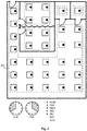
- Fig. 1 illustrates an example of a lighting system that is used to illuminate various parts of an office space.
- the black dot in each square marks a sensor; here it is assumed that each luminaire comprises a sensor of its own.
- the type of sensor that is used is not essential for the purposes of the present invention.
- the sensors are movement sensors based on passively detecting changes in infrared radiation.
- a follower relationship is a software instruction for one device (follower device) of the lighting system to react upon a message transmitted by another device (followed device) of the lighting system.
- the followed device is a sensor and the message transmitted is an announcement that the sensor detected movement.
- the four luminaires in the entrance hall belong to a first group 101.
- the three other follower relationships are software instructions to react upon messages transmitted by the three other sensors in the first group 101.
- the software instructions are instructions to light up upon receiving a message transmitted by any of the sensors, indicating that such sensor detected movement. In other words, if movement is detected anywhere within the entrance hall, all luminaires in the first group 101 light up. Such an instruction may interpreted to also tell the luminaire to maintain its light-up state if it was already on when it received the message.
- groups in fig. 1 are a second group 102 that covers the open-plan-type office space; a third group 103 that covers the coffee room; a fourth group 104 that covers the toilet; a fifth group 105 that covers a storage room; a sixth group 106 that covers a first meeting room; and a seventh group 107 that covers a second meeting room.
- the number of devices in a group may vary: in this example there are two groups 104 and 105 that have only one luminaire (and one sensor) each, while the largest group 102 has a total of 15 luminaires (and sensors).
- a sensor finding is a piece of information that indicates a user having been detected by a particular sensor at a particular moment of time.
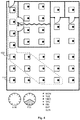
- the change in grouping between figs. 1 and 2 can be accomplished by collecting a plurality of sensor findings from the devices of the lighting system over a period of time, noting a regularity of the kind described above, and determining a set of new follower relationships for at least some of the devices of the lighting systems.
- These new follower relationships are time-dependent in the sense that they are in force only every working day from 8 A.M. to 4 P.M., because these were the hours during which the frequent activity was detected in groups 101, 102, and 103 in the collected sensor findings.
- all luminaires in the combined group 202 light up and remain on as long as at least one of the sensors in this combined group detects a user and transmits the corresponding message.
- Fig. 3 illustrates another example.
- the sensors in both meeting room groups 106 and 107 detected very frequent movement and/or presence of users, and produced corresponding sensor findings, between 10 and 12 A.M. every Friday morning.
- sensor findings could indicate for example that there is a regular department meeting every Friday between 10 and 12 A.M., for which the foldable partition between the meetings rooms is taken aside.
- New follower relationships are then determined for and assigned to the devices that originally were in the meeting room groups 106 and 107 on the basis of said sensor findings.
- These new follower relationships are time-dependent: between 10 and 12 A.M. every Friday morning each luminaire in the combined group 306 is to react upon a message transmitted by any sensor in the combined group 306, by lighting up if it was not on already and by remaining on if it was on already.
- Fig. 4 illustrates another example, emphasizing that the regrouping with new follower relationships does not need to follow the same borderlines between groups as the original grouping.
- the collected sensor findings indicated that a small group of employees have the habit of working late each working day. These employees occupy certain tables in the middle of the open-plan office, and they have the habit of working until 8 P.M. at most.
- a group 402 is formed of those luminaires the sensors of which seemed to have regularly detected the late-working users according to the collected sensor findings.
- the luminaires in the entrance hall are included in the group 402, because the escape route from the space should remain illuminated for safety reasons.
- a time scale of the time-dependent, new follower relationships is defined at least in fractions of a day.
- a time-dependent follower relationship is a software instruction for one device of the lighting system to react upon a message transmitted by another device of the lighting system in a different way depending on what time of the day it is.
- This dependency on the time of the day is illustrated with the schematic clock faces in figs. 2 , 3 , and 4 .
- Other ways of defining the time scale can be found through experimenting.
- the period of time during which the sensor findings are collected should be long enough in relation to the planned time scale so that meaningful conclusions can be drawn from the observed regularities in the sensor findings.
- the time scale will be defined in fractions of the day, sensor findings should be collected for at least a number of days, and preferably at least two or more weeks, in order to be able to assume that the regularly occurring phenomena in this environment have been recorded.
- time-dependent follower relationships are software instructions for a particular luminaire of the lighting system to light up upon receiving a message transmitted by a particular movement detector if said message came in a first time interval, but not to light up upon receiving such a message from said movement detector if said message came in a second, different time interval. More versatile ways of reacting are described in the following.
- a solution may be provided in which at least one of the new follower relationships is a software instruction for a particular luminaire of the lighting system to light up to an illumination level upon receiving a message transmitted by a particular movement detector, so that said illumination level depends on the time when the message came.
- luminaire 410 would belong to group 202 until 4 P.M. (see fig. 2 ), lighting up to 100% if it received a message transmitted by any movement detector in group 202. After 4 P.M. the luminaire 410 does not belong to group 402, so its new follower relationship could be e.g. a software instruction to light up to 50% upon receiving a message transmitted by any of the movement detectors in group 402.
- the levels to light up to may even differ within the same group of luminaires, at least if there exists a mechanism through which the luminaire (or the device giving direct lighting commands to the luminaire) knows the relative distance between the luminaire and the sensor that transmitted the message. This may be possible if the distances between devices are known to the devices in question, or if the messaging protocol defines some kind of an accumulating hop count or other measure from which a receiving device can deduce, how long distance the message has travelled. If the messages are transmitted wirelessly it may also be possible to use a received signal strength indicator or the like to deduce, from what distance the message was transmitted.
- the time-dependent follower relationship may be a software instruction for a particular luminaire of the lighting system to dim down after a delay after receiving a message transmitted by a particular movement detector, so that the length of the delay depends on the time when the message came (and possibly on other factors, like the distance at which the transmitting movement detector is from the receiving luminaire).
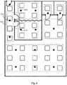
- Fig. 5 illustrates an embodiment in which the time-dependent follower relationships define a direction-dependent grouping. Above it was already pointed out how the most active hours in an office may call for maintaining most of the space illuminated, while during less active hours it is advisable to consider, whether some of the lights could be kept off or at least at a lower level in order to save energy.
- the luminaires in the coffee room group 103 have been assigned follower relationships instructing them to react upon messages transmitted by the movement detector in the toilet group 104 (in addition to messages transmitted by the movement detectors of their own group 103). However, the luminaire in the toilet group 104 has not been assigned any follower relationship that would instruct it to react upon messages transmitted by the movement detectors in the coffee room group 103.
- the luminaires in the open-plan office group 102 have been assigned follower relationships instructing them to react upon messages transmitted by any movement detector in the coffee room group 103 (in addition to messages transmitted by the movement detectors of their own group 102).
- the luminaires in the coffee room group 103 have not been assigned any follower relationships that would instruct them to react upon messages transmitted by the movement detectors in the open-plan office group 102.
- Another embodiment illustrated in fig. 5 is that of at least some of the luminaires belonging to two or more groups simultaneously.
- the collected sensor findings may show for example that it is actually relatively hard to correctly predict, at least like something between 9 A.M. and 3 P.M. on working days, whether a user detected in the entrance hall will move into any of the meeting rooms or not.
- As a courtesy measure towards a user who is actually going to a meeting room it would be nice to have the lights there go on already in preparation, but on the other hand switching lights on for no reason is a waste of energy.
- the embodiment of fig. 5 suggests that the luminaire closest to the door in each meeting room should actually belong to the entrance hall group 101 in addition to its own, meeting-room-specific group between 9 A.M. and 3 P.M.
- These doorway luminaires of the meeting rooms have been assigned follower relationships telling them to react upon messages transmitted by any of the movement sensors in the entrance hall group, for example by dimming up to 80% so that a nice and convenient welcoming light appears in the doorway of each meeting room.
- Fig. 6 illustrates an alternative embodiment, in which so-called area sensors are used.
- the original, first follower relationships are assigned to the luminaires based on some knowledge about the locations of the sensors on one hand the luminaires on the other hand.
- These, as well as the second, time-dependent follower relationships group a number of luminaires of the lighting system into a follower group of a particular movement detector. For each luminaire of such a follower group a corresponding follower relationship is a software instruction to react upon a message indicating that said particular movement detector detected movement.
- follower relationships assigned to luminaires may involve instructions for other kinds of action, and the lighting system may comprise other devices than luminaires or lights.
- the analysis of collected sensor findings may lead to the possibility of giving time-dependent instructions also to such other devices.
- the described method may comprise identifying, from the collected sensor findings, at least one sensor of the lighting system that in view of the collected sensor findings appears to detect little movement relative to other sensors of said lighting system during a regularly occurring part of the time. Then the method may comprise instructing the identified sensor to go into a power saving mode for future occurrences of such regularly occurring parts of the time. This may not be that significant if the sensors are e.g. passive infrared sensors that are known to consume relatively little energy even during active operation, but there are other sensor types like active imaging sensors with which the achieved savings in power consumption may be significant.
- Figs. 7 and 8 illustrate some examples of how communications may be arranged within the lighting system and between the lighting system and a possible external control apparatus.
- the lighting system comprises sensor-equipped luminaire units.
- Luminaire unit 721 is shown as an example. It comprises the actual luminaire part 722, a sensor part 723, and a control unit 724 that is also responsible for communications with other devices.
- the control units of the luminaire units are equipped with wireless transceivers in order to make them communicate with each other.
- the control units may constitute a BLE (Bluetooth Low Energy) mesh network, a ZigBee network, a WiFi network, or some other wireless communications network with relatively short distances between the communicating stations.
- a gateway unit 725 which constitutes a communications gateway to an external network 726 and further to an external
- the lighting system comprises luminaires 822 and sensors 823, all coupled to a wired control bus 829 that can be for example a DALI (Digital Addressable Lighting Interface) bus, a KNX bus, a Modbus, or any other suitable control bus on which addressed messages can be received and transmitted.
- a control apparatus 827 is also coupled to the control bus 829 so that it can exchange messages with the sensors 823 and the luminaires 822.
- the control apparatus 827 may have a built-in user interface part 828 or it may have a connector or wireless transceiver through which a user interface part can be connected when needed.
- the features shown in figs. 7 and 8 are examples and not all necessary, and they do not exclude the use of other kinds of communications and distribution of tasks between the devices.
- one of the control units 724 can take the role of a control apparatus, if it has sufficient processing power.
- Functions of the control apparatus could additionally or alternatively be located in the gateway unit 725.
- the device shown as the control apparatus 827 could actually operate just as a gateway unit, so that the actual control apparatus could be somewhere else, for example at some other node of an external communications network like in fig. 7 .
- Figs. 7 and 8 also illustrate how the controlling functions of the lighting system may be organized in various ways between the devices.
- a bus-controlled lighting system like that in fig. 8 it is not necessary to give the sensors and luminaires any more intelligence than what is needed to obey direct commands from the control apparatus 827.
- the act of assigning a follower relationship to a luminaire does not necessarily involve transmitting anything to the luminaire itself.
- the control apparatus 827 may simply store the follower relationship in its own memory; the fact that it concerns a particular luminaire is enough to say that it is "assigned" to that luminaire.
- the control apparatus 827 receives a sensor finding on the bus 829 from one of the sensors 823, it just checks its own memory to see, what kind of reaction it should command the appropriate luminaire(s) to perform.
- the control apparatus of fig. 9 is equipped for controlling the operation of a plurality of devices of a lighting system. It comprises a sensor findings collecting subsystem 901 that is configured to collect a plurality of sensor findings from said devices of said lighting system over a period of time.
- a sensor finding is a piece of information indicative of a user having been detected by a particular sensor at a particular moment of time.
- the sensor findings collection subsystem 901 may store the sensor findings it receives, for example in the form of a database in which the stored sensor findings can be accessed through various kinds of structured queries.
- the control apparatus comprises a processing subsystem 902 that is configured to determine follower relationships for the plurality of devices on the basis of sensor findings collected by the sensor findings collecting subsystem 901.
- a follower relationship is a software instruction for one device of the lighting system to react upon a message transmitted by another device of said lighting system.
- the processing subsystem 902 is configured to make at least some of the determined follower relationships time-dependent in the sense that they define different ways of reacting depending on time.
- the control apparatus comprises an instructions composing subsystem 903 that is configured to formulate the follower relationships determined by the processing subsystem 902 into instruction messages for the devices of the lighting system.
- the control apparatus comprises also a communications subsystem 904 that is configured to convey received sensor finding messages as sensor findings into the sensor findings collecting subsystem 901, and to transmit the instruction messages coming from the instructions composing subsystem towards the devices of the lighting system.
- the control apparatus may comprise a program memory 905 for storing the machine-readable software instructions that the processing subsystem 902 executes in order to determine new follower relationships on the basis of the collected sensor findings.
- the control apparatus may also comprise a programming interface 906 for providing external access to said program memory 905. This way a programmer may examine the past operation of the system and/or upload new machine-readable instructions for execution by the processing subsystem 902.
- the step of determining second follower relationships for the plurality of devices on the basis of the plurality of collected sensor findings is preferably performed through unsupervised machine learning.
- the operation of the processing subsystem 902 involves unsupervised machine learning algorithms, which may be based on neural networks for example. They compare observed patterns in the sensor findings collected from different sensors and identify those sensors that exhibit temporally similar behaviour patterns. For example, in a corridor sensors see motion one after another when person walks down the corridor. This way the dynamical grouping (i.e. the determining of new, time-dependent follower relationships) can be done without prior knowledge on the location of the sensors and completely automatically. No human involvement is necessarily needed in the setting up of groups - apart from the detection of human users being the source of sensor signals.
- Fig. 9 can also be read as an illustration of a computer program product.
- a computer program product is meant for execution by a control apparatus that is controlling the operation of a plurality of devices of a lighting system.
- the computer program product comprises one or more sets of one or more machine-readable instructions configured to make, when executed on one or more processors of the control apparatus, the control apparatus perform certain steps. These include collecting a plurality of sensor findings from said devices of said lighting system over a period of time, as illustrated by block 901.
- the steps include also determining follower relationships for said plurality of devices on the basis of said plurality of sensor findings, as illustrated by block 902. At least some of said follower relationships are time-dependent, as has been described above.
- the steps include also formulating said follower relationships into instruction messages for said devices of said lighting system as illustrated by block 903, and transmitting said instruction messages towards said devices of said lighting system as illustrated by block 904.
Priority Applications (1)
| Application Number | Priority Date | Filing Date | Title |
|---|---|---|---|
| EP18194765.6A EP3624561A1 (fr) | 2018-09-17 | 2018-09-17 | Procédé et dispositif de groupage dynamique de dispositifs dans un système d'éclairage |
Applications Claiming Priority (1)
| Application Number | Priority Date | Filing Date | Title |
|---|---|---|---|
| EP18194765.6A EP3624561A1 (fr) | 2018-09-17 | 2018-09-17 | Procédé et dispositif de groupage dynamique de dispositifs dans un système d'éclairage |
Publications (1)
| Publication Number | Publication Date |
|---|---|
| EP3624561A1 true EP3624561A1 (fr) | 2020-03-18 |
Family
ID=63787695
Family Applications (1)
| Application Number | Title | Priority Date | Filing Date |
|---|---|---|---|
| EP18194765.6A Withdrawn EP3624561A1 (fr) | 2018-09-17 | 2018-09-17 | Procédé et dispositif de groupage dynamique de dispositifs dans un système d'éclairage |
Country Status (1)
| Country | Link |
|---|---|
| EP (1) | EP3624561A1 (fr) |
Citations (9)
| Publication number | Priority date | Publication date | Assignee | Title |
|---|---|---|---|---|
| US20110307112A1 (en) * | 2010-06-15 | 2011-12-15 | Redwood Systems, Inc. | Goal-based control of lighting |
| WO2014118676A1 (fr) | 2013-02-01 | 2014-08-07 | Koninklijke Philips N.V. | Groupement automatique par lumière et son |
| WO2014145506A2 (fr) | 2013-03-15 | 2014-09-18 | Cooper Technologies Company | Systèmes et procédés pour système d'éclairage à mise en service et localisation automatiques |
| EP2944161B1 (fr) | 2013-01-08 | 2017-05-17 | Philips Lighting Holding B.V. | Procédé d'attribution de dispositifs d'éclairage à un groupe |
| WO2017162550A1 (fr) | 2016-03-24 | 2017-09-28 | Philips Lighting Holding B.V. | Commande d'éclairage utilisant une distribution spatiale d'utilisateurs |
| WO2018087650A1 (fr) | 2016-11-08 | 2018-05-17 | Zumtobel Lighting Inc. | Attribution de dispositifs de luminaire pouvant être commandés à des groupes de commande |
| US9992838B1 (en) | 2017-05-01 | 2018-06-05 | Gooee Limited | Automated luminaire identification and group assignment devices, systems, and methods using dimming function |
| EP2935987B1 (fr) | 2012-12-18 | 2018-07-04 | Cree, Inc. | Luminaire pour regroupement automatisé |
| US20180195706A1 (en) * | 2010-11-04 | 2018-07-12 | Digital Lumens, Inc. | Method, apparatus, and system for occupancy sensing |
-
2018
- 2018-09-17 EP EP18194765.6A patent/EP3624561A1/fr not_active Withdrawn
Patent Citations (9)
| Publication number | Priority date | Publication date | Assignee | Title |
|---|---|---|---|---|
| US20110307112A1 (en) * | 2010-06-15 | 2011-12-15 | Redwood Systems, Inc. | Goal-based control of lighting |
| US20180195706A1 (en) * | 2010-11-04 | 2018-07-12 | Digital Lumens, Inc. | Method, apparatus, and system for occupancy sensing |
| EP2935987B1 (fr) | 2012-12-18 | 2018-07-04 | Cree, Inc. | Luminaire pour regroupement automatisé |
| EP2944161B1 (fr) | 2013-01-08 | 2017-05-17 | Philips Lighting Holding B.V. | Procédé d'attribution de dispositifs d'éclairage à un groupe |
| WO2014118676A1 (fr) | 2013-02-01 | 2014-08-07 | Koninklijke Philips N.V. | Groupement automatique par lumière et son |
| WO2014145506A2 (fr) | 2013-03-15 | 2014-09-18 | Cooper Technologies Company | Systèmes et procédés pour système d'éclairage à mise en service et localisation automatiques |
| WO2017162550A1 (fr) | 2016-03-24 | 2017-09-28 | Philips Lighting Holding B.V. | Commande d'éclairage utilisant une distribution spatiale d'utilisateurs |
| WO2018087650A1 (fr) | 2016-11-08 | 2018-05-17 | Zumtobel Lighting Inc. | Attribution de dispositifs de luminaire pouvant être commandés à des groupes de commande |
| US9992838B1 (en) | 2017-05-01 | 2018-06-05 | Gooee Limited | Automated luminaire identification and group assignment devices, systems, and methods using dimming function |
Similar Documents
| Publication | Publication Date | Title |
|---|---|---|
| US10088820B2 (en) | Occupancy based demand controlled utility system | |
| EP2919562B1 (fr) | Luminaire d'apprentissage et dispositif de commande d'apprentissage pour un luminaire | |
| EP3171674B1 (fr) | Luminaire d'apprentissage et dispositif de commande d'apprentissage pour un luminaire utilisant la logique floue | |
| EP2717655B1 (fr) | Système de contrôle de l'éclairage | |
| CN110167241B (zh) | 一种室内智慧照明的数据传输控制方法及系统 | |
| US10798800B2 (en) | System and method for automatically creating and operating a functional association of lights | |
| WO2006077561A2 (fr) | Systeme et procede pour la configuration de systeme de controle pour plusieurs dispositifs | |
| US10859990B2 (en) | Method and system for utilizing a device's user location to monitor and control the device power usage | |
| KR101214235B1 (ko) | 무선 센싱 모듈, 무선 조명 제어 장치 및 무선 조명 시스템 | |
| CN112020184B (zh) | 一种基于物联网的楼宇照明系统及方法 | |
| EP3399844B1 (fr) | Système et procédé pour créer et faire fonctionner automatiquement une association fonctionnelle de lumières | |
| EP3624561A1 (fr) | Procédé et dispositif de groupage dynamique de dispositifs dans un système d'éclairage | |
| CN210958917U (zh) | 智能家居照明控制系统 | |
| EP3300459B1 (fr) | Système et procédé de commande d'éclairage basé sur la localisation d'utilisateur | |
| JP7167787B2 (ja) | 照明制御システム | |
| KR20190017091A (ko) | 카운트 센서를 이용하는 순차 자동제어 조명 시스템 | |
| KR101921906B1 (ko) | IoT 기반 인체의 이동에 따른 조명의 핸드오버 제어 방법 및 그 장치 | |
| EP4236629A1 (fr) | Commande d'éclairage | |
| JP2017134936A (ja) | 照明制御装置、照明制御システムおよびプログラム | |
| EP4271139A1 (fr) | Contrôle d'éclairage | |
| EP3863375A1 (fr) | Commande d'éclairage | |
| FI129261B (en) | Lighting control | |
| EP3749060B1 (fr) | Commande d'éclairage à configuration automatique | |
| JP2001155868A (ja) | 照明制御システム | |
| WO2022161870A1 (fr) | Détection rf avec latence constante |
Legal Events
| Date | Code | Title | Description |
|---|---|---|---|
| PUAI | Public reference made under article 153(3) epc to a published international application that has entered the european phase |
Free format text: ORIGINAL CODE: 0009012 |
|
| STAA | Information on the status of an ep patent application or granted ep patent |
Free format text: STATUS: THE APPLICATION HAS BEEN PUBLISHED |
|
| AK | Designated contracting states |
Kind code of ref document: A1 Designated state(s): AL AT BE BG CH CY CZ DE DK EE ES FI FR GB GR HR HU IE IS IT LI LT LU LV MC MK MT NL NO PL PT RO RS SE SI SK SM TR |
|
| AX | Request for extension of the european patent |
Extension state: BA ME |
|
| STAA | Information on the status of an ep patent application or granted ep patent |
Free format text: STATUS: REQUEST FOR EXAMINATION WAS MADE |
|
| 17P | Request for examination filed |
Effective date: 20200706 |
|
| RBV | Designated contracting states (corrected) |
Designated state(s): AL AT BE BG CH CY CZ DE DK EE ES FI FR GB GR HR HU IE IS IT LI LT LU LV MC MK MT NL NO PL PT RO RS SE SI SK SM TR |
|
| STAA | Information on the status of an ep patent application or granted ep patent |
Free format text: STATUS: EXAMINATION IS IN PROGRESS |
|
| 17Q | First examination report despatched |
Effective date: 20220909 |
|
| REG | Reference to a national code |
Ref country code: DE Ref legal event code: R079 Free format text: PREVIOUS MAIN CLASS: H05B0037020000 Ipc: H05B0047105000 |
|
| RIC1 | Information provided on ipc code assigned before grant |
Ipc: H05B 47/175 20200101ALI20230930BHEP Ipc: H05B 47/16 20200101ALI20230930BHEP Ipc: H05B 47/105 20200101AFI20230930BHEP |
|
| STAA | Information on the status of an ep patent application or granted ep patent |
Free format text: STATUS: THE APPLICATION HAS BEEN WITHDRAWN |
|
| 18W | Application withdrawn |
Effective date: 20240216 |