EP3624549B1 - Methods and devices for controlling rrc state - Google Patents
Methods and devices for controlling rrc state Download PDFInfo
- Publication number
- EP3624549B1 EP3624549B1 EP18913785.4A EP18913785A EP3624549B1 EP 3624549 B1 EP3624549 B1 EP 3624549B1 EP 18913785 A EP18913785 A EP 18913785A EP 3624549 B1 EP3624549 B1 EP 3624549B1
- Authority
- EP
- European Patent Office
- Prior art keywords
- rrc
- state
- terminal device
- connection resume
- target
- Prior art date
- Legal status (The legal status is an assumption and is not a legal conclusion. Google has not performed a legal analysis and makes no representation as to the accuracy of the status listed.)
- Revoked
Links
- 238000000034 method Methods 0.000 title claims description 46
- 230000000737 periodic effect Effects 0.000 claims description 7
- 230000004044 response Effects 0.000 claims description 5
- 238000010586 diagram Methods 0.000 description 8
- 238000004891 communication Methods 0.000 description 7
- 230000006870 function Effects 0.000 description 7
- 238000010295 mobile communication Methods 0.000 description 7
- 230000005540 biological transmission Effects 0.000 description 4
- 230000011664 signaling Effects 0.000 description 4
- 230000008878 coupling Effects 0.000 description 3
- 238000010168 coupling process Methods 0.000 description 3
- 238000005859 coupling reaction Methods 0.000 description 3
- 238000005516 engineering process Methods 0.000 description 3
- 230000007704 transition Effects 0.000 description 3
- GHOKWGTUZJEAQD-ZETCQYMHSA-N (D)-(+)-Pantothenic acid Chemical compound OCC(C)(C)[C@@H](O)C(=O)NCCC(O)=O GHOKWGTUZJEAQD-ZETCQYMHSA-N 0.000 description 2
- 230000001960 triggered effect Effects 0.000 description 2
- 230000006399 behavior Effects 0.000 description 1
- VJYFKVYYMZPMAB-UHFFFAOYSA-N ethoprophos Chemical compound CCCSP(=O)(OCC)SCCC VJYFKVYYMZPMAB-UHFFFAOYSA-N 0.000 description 1
- 230000000977 initiatory effect Effects 0.000 description 1
- 230000003287 optical effect Effects 0.000 description 1
- 230000008520 organization Effects 0.000 description 1
- 230000008569 process Effects 0.000 description 1
- 230000009467 reduction Effects 0.000 description 1
- 239000007787 solid Substances 0.000 description 1
Images

Classifications
-
- H—ELECTRICITY
- H04—ELECTRIC COMMUNICATION TECHNIQUE
- H04W—WIRELESS COMMUNICATION NETWORKS
- H04W76/00—Connection management
- H04W76/20—Manipulation of established connections
- H04W76/27—Transitions between radio resource control [RRC] states
-
- H—ELECTRICITY
- H04—ELECTRIC COMMUNICATION TECHNIQUE
- H04W—WIRELESS COMMUNICATION NETWORKS
- H04W76/00—Connection management
- H04W76/10—Connection setup
- H04W76/11—Allocation or use of connection identifiers
-
- H—ELECTRICITY
- H04—ELECTRIC COMMUNICATION TECHNIQUE
- H04W—WIRELESS COMMUNICATION NETWORKS
- H04W76/00—Connection management
- H04W76/10—Connection setup
- H04W76/19—Connection re-establishment
-
- H—ELECTRICITY
- H04—ELECTRIC COMMUNICATION TECHNIQUE
- H04W—WIRELESS COMMUNICATION NETWORKS
- H04W76/00—Connection management
- H04W76/20—Manipulation of established connections
- H04W76/28—Discontinuous transmission [DTX]; Discontinuous reception [DRX]
-
- H—ELECTRICITY
- H04—ELECTRIC COMMUNICATION TECHNIQUE
- H04W—WIRELESS COMMUNICATION NETWORKS
- H04W76/00—Connection management
- H04W76/30—Connection release
-
- Y—GENERAL TAGGING OF NEW TECHNOLOGICAL DEVELOPMENTS; GENERAL TAGGING OF CROSS-SECTIONAL TECHNOLOGIES SPANNING OVER SEVERAL SECTIONS OF THE IPC; TECHNICAL SUBJECTS COVERED BY FORMER USPC CROSS-REFERENCE ART COLLECTIONS [XRACs] AND DIGESTS
- Y02—TECHNOLOGIES OR APPLICATIONS FOR MITIGATION OR ADAPTATION AGAINST CLIMATE CHANGE
- Y02D—CLIMATE CHANGE MITIGATION TECHNOLOGIES IN INFORMATION AND COMMUNICATION TECHNOLOGIES [ICT], I.E. INFORMATION AND COMMUNICATION TECHNOLOGIES AIMING AT THE REDUCTION OF THEIR OWN ENERGY USE
- Y02D30/00—Reducing energy consumption in communication networks
- Y02D30/70—Reducing energy consumption in communication networks in wireless communication networks
Definitions
- the present disclosure relates to wireless communication technologies, and more particularly to methods and devices for controlling a Radio Resource Control (RRC) state.
- RRC Radio Resource Control
- Enhanced Mobile Broadband eMBB
- Ultra Reliable Low Latency Communication URLLC
- massive Machine Type Communication mMTC
- a new RRC state i.e., an RRC inactive (RRC_INACTIVE) state, is defined for reduction of air interface signaling, fast resume of wireless connections and data services.
- This state is different from an RRC idle (RRC_IDLE) state and an RRC connected (RRC_CONNECTED) state.
- a network side When user Equipment (UE) is in an RRC_INACTIVE state, a network side will configure a Radio Access Network (RAN) paging area for the UE by dedicated signaling.
- the RAN paging area may be one or more cells.
- the network side will not be notified of the movement of the UE within the area and the mobility behavior in an idle state is followed, namely, the principle of cell reselection is followed.
- the UE moves out of the paging area configured by the RAN, the UE is triggered to resume the RRC connection and re-acquire the paging area configured by the RAN.
- a base station such as gNB
- CN Core Network
- downlink data is transmitted to the UE and the network side initiates paging on the side of RAN to prompt the UE to enter the connected state.
- the UE itself initiates an RAN location area update, such as a periodic RAN location update or a cross-region location update.
- an RAN location area update such as a periodic RAN location update or a cross-region location update.
- the UE has needs for transmitting uplink data, which allows the UE to enter the connected state.
- embodiments of the present disclosure provide methods and devices for controlling an RRC state respectively according to independent claims 1, 3 and 5, 6.
- eMBB is intended to allow users to obtain multimedia contents, services and data and its service demand is growing rapidly. Since eMBB may be deployed in various scenarios, such as indoors, urban areas and rural areas, there will be great differences in its service capabilities and requirements. Therefore, services are analyzed in combination with specific deployment scenarios.
- the URLLC includes typical characteristics of high connection density, small data volume, delay-insensitive service, low cost and long service life of modules.
- RRC_IDLE state the mobility refers to the UE based cell reselection and paging is initiated by a CN and a paging area is configured by the CN. There is no UE AS context on a base station side. There is no RRC connection.
- RRC_CONNECTED state there is an RRC connection and there is a UE AS context on the base station and the UE sides.
- the network side knows that the location of the UE is at a specific cell level.
- the mobility is controlled by the network side.
- Unicast data can be transmitted between the UE and the base station.
- RRC_INACTIVE state the mobility refers to the UE-based cell reselection and there is a connection between a CN and an RAN and UE AS contexts exist on a certain base station; paging is triggered by the RAN and a RAN-based paging area is managed by the RAN and the network side knows that the location of the UE is at a level of the RAN based paging area.
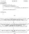
- Fig. 1 is a schematic diagram of an RRC connection resume procedure. As shown in Fig. 1 , the RRC connection resume procedure includes the following procedures:
- step 101 an UE is in an INACTIVE state and an RRC connection is to be resumed.
- step 102 the UE sends a preamble to a gNB.
- step 103 the gNB sends a random access response (RAR) to the UE.
- RAR random access response
- step 104 the UE sends an RRC connection resume request message to the gNB.
- the gNB requests UE context information from an anchor gNB.
- step 106 the gNB sends an RRC connection resume message to the UE.
- step 107 the UE enters an RRC_CONNECTED state.
- the purpose of the embodiment of the present disclosure is to control, by a network side, the UE to enter any one of the RRC_CONNECTED state, an RRC_INACTIVE state and an RRC_IDLE state.
- Fig. 2 is a first schematic flowchart of a method for controlling an RRC state according to an embodiment of the present disclosure. As shown in Fig. 2 , the method includes the following steps:
- a terminal device sends a first RRC message to a network device.
- the first RRC message includes an RRC connection resume request message.
- the terminal may be any device which is capable of communicating with the network device, such as a mobile phone, a tablet computer, a notebook computer, a desktop computer or the like.
- the network device refers to a base station, such as a gNB in 5G.
- the terminal device when initiating an RRC connection resume procedure, the terminal device initiates a random access procedure at first and then sends an RRC connection resume request message (corresponding to the first RRC message) to the network side in MSG3.
- the terminal device receives a second RRC message sent by the network device.
- the second RRC message carries first indication information, which is used for indicating a target RRC state of the terminal device.
- the second RRC message includes an RRC connection resume message, an RRC connection release message, or a newly defined RRC message.
- the first RRC message carries indication information for indicating a reason for the RRC connection resume, wherein the indication information for indicating the reason for the RRC connection resume is used by the network device to determine the target RRC state of the terminal device in a connection resume procedure.
- step 203 the terminal device enters the target RRC state based on the first indication information.
- the target RRC state is an RRC connected state, an RRC inactive state, or an RRC idle state.
- the terminal device uses locally stored configuration information that corresponds to the RRC inactive state.
- the terminal device uses the configuration information carried in the second RRC message and corresponding to the RRC inactive state.
- the configuration information corresponding to the RRC inactive state includes at least one of I-RNTI, RAN notification area, RAN DRX cycle, periodic RAN notification area update timer.
- Fig. 3 is a second schematic flowchart of a method for controlling an RRC state according to an embodiment of the present disclosure. As shown in Fig. 3 , the method includes the following steps:
- step 301 a UE is in an INACTIVE state and an RRC connection is to be resumed.
- step 302 the UE sends a preamble to a gNB.
- step 303 the gNB sends a random access response (RAR) to the UE.
- RAR random access response
- step 304 the UE sends an RRC connection resume request message to the gNB.
- the gNB determines a target RRC state of the UE in this RRC connection resume procedure according to indication information for indicating a reason for the RRC connection resume in the RRC connection resume request message.
- the gNB requests UE context information from an anchor gNB.
- the gNB sends an RRC connection resume message to the UE.
- the RRC connection resume message carries indication information which is used for indicating the target RRC state of the UE.
- step 307 the UE enters the target RRC state according to the indication information.
- the UE uses the originally stored configuration information corresponding to the RRC_INACTIVE state by default.
- step 308 the UE sends an RRC connection resume complete message to the gNB.
- the UE may not perform the step 308.
- Fig. 4 is a third schematic flowchart of a method for controlling an RRC state according to an embodiment of the present disclosure. As shown in Fig. 4 , the method includes the following steps:
- step 401 a UE is in an INACTIVE state and an RRC connection is to be resumed.
- step 402 the UE sends a preamble to a gNB.
- step 403 the gNB sends a random access response (RAR) to the UE.
- RAR random access response
- step 404 the UE sends an RRC connection resume request message to the gNB.
- the gNB determines a target RRC state of the UE in this RRC connection resume procedure according to indication information for indicating a reason for the RRC connection resume in the RRC connection resume request message.
- step 405 the gNB requests UE context information from an anchor gNB.
- the gNB sends an RRC connection release message to the UE.
- the RRC connection release message carries indication information which is used for indicating the target RRC state of the UE.
- step 407 the UE enters the target RRC state according to the indication information.
- the UE uses the originally stored configuration information corresponding to the RRC_INACTIVE state by default.
- Fig. 5 is a fourth schematic flowchart of a method for controlling an RRC state according to an embodiment of the present disclosure. As shown in Fig. 5 , the method includes the following steps:
- a network device receives a first RRC message sent by a terminal device.
- the first RRC message includes an RRC connection resume request message.
- the network device sends a second RRC message to the terminal device.
- the second RRC message carries first indication information, which is indicative of a target RRC state of the terminal device, so that the terminal device enters the target RRC state based on the first indication information.
- the second RRC message may carry configuration information corresponding to the RRC inactive state or may not carry configuration information corresponding to the RRC inactive state.
- the configuration information corresponding to the RRC inactive state includes at least one of I-RNTI, RAN notification area, RAN DRX cycle, periodic RAN notification area update timer.
- the second RRC message includes an RRC connection resume message, an RRC connection release message, or a newly defined RRC message.
- the first RRC message carries indication information for indicating a reason for the RRC connection resume, wherein the indication information for indicating the reason for the RRC connection resume is used by the network device to determine the target RRC state of the terminal device in a connection resume procedure.
- the target RRC state is an RRC connected state, an RRC inactive state, or an RRC idle state.
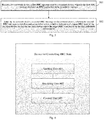
- Fig. 6 is a first schematic structural diagram of a device for controlling an RRC state according to an embodiment of the present disclosure. As shown in Fig. 6 , the device includes a sending unit 601, a receiving unit 602 and a control unit 603.
- the sending unit 601 is configured to send to a network device a first RRC message which includes an RRC connection resume request message.
- the receiving unit 602 is configured to receive a second RRC message sent by the network device, the second RRC message carrying first indication information which is indicative of a target RRC state of the terminal device.
- the control unit 603 is configured to control the terminal device to enter the target RRC state based on the first indication information.
- the terminal device uses locally stored configuration information that corresponds to the RRC inactive state.
- the terminal device uses the configuration information that is carried in the second RRC message and corresponds to the RRC inactive state.
- the configuration information corresponding to the RRC inactive state includes at least one of I-RNTI, RAN notification area, RAN DRX cycle, periodic RAN notification area update timer.
- the second RRC message includes an RRC connection resume message, an RRC connection release message, or a newly defined RRC message.
- the first RRC message carries indication information for indicating a reason for the RRC connection resume, wherein the indication information for indicating the reason for the RRC connection resume is used by the network device to determine the target RRC state of the terminal device in a connection resume procedure.
- the target RRC state is an RRC connected state, an RRC inactive state, or an RRC idle state.
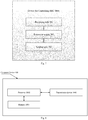
- Fig. 7 is a second schematic structural diagram of a device for controlling an RRC state according to an embodiment of the present disclosure. As shown in Fig. 7 , the device includes a receiving unit 701 and a sending unit 702.
- the receiving unit 701 is configured to receive a first RRC message sent by a terminal device, the first RRC message including an RRC connection resume request message.
- the sending unit 702 is configured to send a second RRC message to the terminal device, wherein the second RRC message carries first indication information, which is indicative of a target RRC state of the terminal device, so that the terminal device enters the target RRC state based on the first indication information.
- the second RRC message may or may not carry configuration information corresponding to the RRC inactive state.
- the configuration information corresponding to the RRC inactive state includes at least one of I-RNTI, RAN notification area, RAN DRX cycle, periodic RAN notification area update timer.
- the second RRC message includes an RRC connection resume message, an RRC connection release message, or a newly defined RRC message.
- the first RRC message carries indication information for indicating a reason for the RRC connection resume
- the device further includes:
- a determining unit 703 configured to determine the target RRC state of the terminal device in a connection resume procedure based on the indication information for indicating the reason for the RRC connection resume.
- the target RRC state is an RRC connected state, an RRC inactive state, or an RRC idle state.
- the devices for controlling an RRC state may also be stored in a computer readable storage medium when it is implemented as a software function module and sold or used as a stand-alone product.
- a computer readable storage medium when it is implemented as a software function module and sold or used as a stand-alone product.
- the foregoing storage medium includes various media that can store program codes, such as a USB flash disk, a mobile hard disk, a read-only memory (ROM), a magnetic disk, or an optical disk. Therefore the embodiments of the present disclosure are not limited to any specific combination of hardware and software.
- an embodiment of the present disclosure further provides a computer storage medium having computer-executable instructions stored thereon.
- the computer-executable instructions When executed by a processor, the computer-executable instructions implement the foregoing methods for controlling the RRC state according to the embodiments of the present disclosure.
- Fig. 8 is a schematic structural diagram of a computer device according to an embodiment of the present disclosure.
- the computer device may be a terminal device or a network device.
- a computer device 100 may include one or more processor 1002 (only one processor is shown, and the processor 1002 may include, but is not limited to a process device such as a Micro Controller Unit (MCU) or a Field Programmable Gate Array (FPGA)), a memory 1004 for storing data and a transmission device 1006 for communication.
- MCU Micro Controller Unit
- FPGA Field Programmable Gate Array
- the structure shown in Fig. 8 is merely illustrative and it does not impose any limitation on the structure of the above electronic device.
- the computer device 100 may also include more or less components than those shown in Fig. 8 , or have a different configuration from that shown in Fig. 8 .
- the memory 1004 may be used to store software programs and modules of application software, for example, program instructions/modules corresponding to the methods in the embodiments of the present disclosure, and the processor 1002 executes various function applications and data processing by running software programs and modules stored in the memory 1004. Namely, the above methods are implemented.
- the memory 1004 may include a high speed random access memory and a non-volatile memory, for example, one or more magnetic storage devices, flash memory, or other non-volatile solid state memory.
- the memory 1004 may further include a remote memory which is remotely deployed from the processor 1002, which can be connected to the computer device 100 via a network. Examples of the network include, but are not limited to, the Internet, intranets, local area networks, mobile communication networks and a combination thereof.
- the transmission device 1006 receives or transmits data via a network.
- a specific example of the network described above may include a wireless network provided by a communication provider of the computer device 100.
- the transmission device 1006 includes a Network Interface Controller (NIC) that can be connected to other network devices through a base station to communicate with the Internet.
- the transmission device 1006 can be a Radio Frequency (RF) module for communicating with the Internet wirelessly.
- NIC Network Interface Controller
- RF Radio Frequency
- the disclosed methods and smart devices may be implemented in other ways.
- the device embodiments described above are merely illustrative.
- the division of the units is only a kind of logical function division. In practice, other division manner may be used.
- multiple units or components may be combined or integrated into another system, or some features may be ignored or not performed.
- the illustrated or discussed mutual coupling or direct coupling or communication connection may be indirect coupling or communication connection through some interfaces, devices or units, and may be in electrical, mechanical or other forms.
- the units described as separated parts may or may not be physically separated, and the parts shown as units may or may not be physical units, that is, may be located in one place, or may be distributed over multiple network units. Some or all of the units may be selected according to actual needs to achieve the objectives of the solutions in the embodiments.
- each functional unit in each embodiment of the present application may be integrated in one second processing unit, or each unit may exist alone physically, or two or more units may be integrated in one unit.
- the above integrated units can be implemented with hardware or hardware and software functional units.
Description
- The present disclosure relates to wireless communication technologies, and more particularly to methods and devices for controlling a Radio Resource Control (RRC) state.
- In order to meet people's pursuit for rate, delay, high-speed mobility, efficacy of services as well as the diversity and complexity of services in the future life, the International Standards Organization of the 3rd Generation Partnership Project (3GPP) has started the study of the 5th Generation (5G) mobile communication technologies.
- The main application of 5G mobile communication technologies includes Enhanced Mobile Broadband (eMBB), Ultra Reliable Low Latency Communication (URLLC) and massive Machine Type Communication (mMTC).
- In the 5G network environment, a new RRC state, i.e., an RRC inactive (RRC_INACTIVE) state, is defined for reduction of air interface signaling, fast resume of wireless connections and data services. This state is different from an RRC idle (RRC_IDLE) state and an RRC connected (RRC_CONNECTED) state.
- When user Equipment (UE) is in an RRC_INACTIVE state, a network side will configure a Radio Access Network (RAN) paging area for the UE by dedicated signaling. The RAN paging area may be one or more cells. The network side will not be notified of the movement of the UE within the area and the mobility behavior in an idle state is followed, namely, the principle of cell reselection is followed. When the UE moves out of the paging area configured by the RAN, the UE is triggered to resume the RRC connection and re-acquire the paging area configured by the RAN. When downlink data arrives at the UE, a base station (such as gNB) that maintains the connection between the RAN and a Core Network (CN) for the UE triggers all cells in the RAN paging area to send paging messages to the UE, so that the UE in the INACTIVCE state can resume the RRC connection and receive data.
- Therefore, as for the transition of the UE from the INACTIVE state to the RRC connection state, there are three situations:
- First, downlink data is transmitted to the UE and the network side initiates paging on the side of RAN to prompt the UE to enter the connected state.
- Second, the UE itself initiates an RAN location area update, such as a periodic RAN location update or a cross-region location update.
- Third, the UE has needs for transmitting uplink data, which allows the UE to enter the connected state.
- At present, the control of the RRC state of the UE by the network side lacks flexibility and has low efficiency. Document HUAWEI ET AL: "Signalling and Procedures for states transition and PAU",3GPP DRAFT; R2-166629 SIGNALLING AND PROCEDURES FOR STATES TRANSITION AND PAU, 3RD GENERATION PARTNERSHIP PROJECT (3GPP), MOBILE COMPETENCE CENTRE ; 650, ROUTE DES LUCIOLES ; F-06921 SOPHIA-ANTIPOLIS,vol. RAN WG2, no. Kaohsiung; 20161010 - 20161014 1 October 2016 (2016-10-01), discloses a method by the eNB for driving the RRC state of the terminal after receiving from it an RRC Resume Request message
- To solve the above technical problem, embodiments of the present disclosure provide methods and devices for controlling an RRC state respectively according to independent claims 1, 3 and 5, 6.
- The accompanying drawings, which constitute a part of the present application, provide further understanding of the present disclosure. Exemplary embodiments of the present disclosure together with the descriptions thereof serve to explain the disclosure and are not intended to be restrictive of the present disclosure.
-
Fig. 1 is a schematic diagram of an RRC connection resume procedure; -
Fig. 2 is a first schematic flowchart of a method for controlling an RRC state; -
Fig. 3 is a second schematic flowchart of a method for controlling an RRC state ; -
Fig. 4 is a third schematic flowchart of a method for controlling an RRC state; -
Fig. 5 is a fourth schematic flowchart of a method for controlling an RRC state; -
Fig. 6 is a first schematic structural diagram of a device for controlling an RRC state ; -
Fig. 7 is a second schematic structural diagram of a device for controlling an RRC state ; -
Fig. 8 is a schematic structural diagram of a computer device ; . - In order to understand features and technical contents of the embodiments of the present disclosure in more detail, the implementation of the embodiments of the present disclosure will be described in detail below with reference to the accompanying drawings. The drawings are provided for illustrative purposes only and are not intended to limit the embodiments of the disclosure.
- The technical solutions of the embodiments of the present disclosure are mainly applied to a 5G mobile communication system. Of course, technical solutions of embodiments of the present disclosure are not limited to the 5G mobile communication system but can be applied to other types of mobile communication systems. The main application scenarios in the 5G mobile communication system will be described as follows:
- 1) the eMBB scenario: eMBB is intended to allow users to obtain multimedia contents, services and data and its service demand is growing rapidly. Since eMBB may be deployed in various scenarios, such as indoors, urban areas and rural areas, there will be great differences in its service capabilities and requirements. Therefore, services are analyzed in combination with specific deployment scenarios.
- 2) the URLLC scenario: typical applications of URLLC include industrial automation, power automation, telemedicine operations, and traffic security, and so on.
- 3) the mMTC scenario: the URLLC includes typical characteristics of high connection density, small data volume, delay-insensitive service, low cost and long service life of modules.
- Three kinds of RRC states in the 5G network environment will be described below:
- 1) RRC_IDLE state: the mobility refers to the UE based cell reselection and paging is initiated by a CN and a paging area is configured by the CN. There is no UE AS context on a base station side. There is no RRC connection.
- 2) RRC_CONNECTED state: there is an RRC connection and there is a UE AS context on the base station and the UE sides. The network side knows that the location of the UE is at a specific cell level. The mobility is controlled by the network side. Unicast data can be transmitted between the UE and the base station.
- 3) RRC_INACTIVE state: the mobility refers to the UE-based cell reselection and there is a connection between a CN and an RAN and UE AS contexts exist on a certain base station; paging is triggered by the RAN and a RAN-based paging area is managed by the RAN and the network side knows that the location of the UE is at a level of the RAN based paging area.
-
Fig. 1 is a schematic diagram of an RRC connection resume procedure. As shown inFig. 1 , the RRC connection resume procedure includes the following procedures: - In
step 101, an UE is in an INACTIVE state and an RRC connection is to be resumed. - In
step 102, the UE sends a preamble to a gNB. - In
step 103, the gNB sends a random access response (RAR) to the UE. - In
step 104, the UE sends an RRC connection resume request message to the gNB. - In
step 105, the gNB requests UE context information from an anchor gNB. - In
step 106, the gNB sends an RRC connection resume message to the UE. - In
step 107, the UE enters an RRC_CONNECTED state. - The purpose of the embodiment of the present disclosure is to control, by a network side, the UE to enter any one of the RRC_CONNECTED state, an RRC_INACTIVE state and an RRC_IDLE state.
- The following part of the description describe the claimed invention.
Fig. 2 is a first schematic flowchart of a method for controlling an RRC state according to an embodiment of the present disclosure. As shown inFig. 2 , the method includes the following steps: - In
step 201, a terminal device sends a first RRC message to a network device. The first RRC message includes an RRC connection resume request message. - In an embodiment of the present disclosure, the terminal may be any device which is capable of communicating with the network device, such as a mobile phone, a tablet computer, a notebook computer, a desktop computer or the like.
- In an embodiment of the present disclosure, the network device refers to a base station, such as a gNB in 5G.
- In an embodiment of the present disclosure, when initiating an RRC connection resume procedure, the terminal device initiates a random access procedure at first and then sends an RRC connection resume request message (corresponding to the first RRC message) to the network side in MSG3.
- In
step 202, the terminal device receives a second RRC message sent by the network device. The second RRC message carries first indication information, which is used for indicating a target RRC state of the terminal device. - In an embodiment of the present disclosure, the second RRC message includes an RRC connection resume message, an RRC connection release message, or a newly defined RRC message.
- In an embodiment, the first RRC message carries indication information for indicating a reason for the RRC connection resume, wherein the indication information for indicating the reason for the RRC connection resume is used by the network device to determine the target RRC state of the terminal device in a connection resume procedure.
- In
step 203, the terminal device enters the target RRC state based on the first indication information. - In an embodiment of the present disclosure, the target RRC state is an RRC connected state, an RRC inactive state, or an RRC idle state.
- In an embodiment, if the target RRC state is an RRC inactive state and the second RRC message does not carry configuration information corresponding to the RRC inactive state, after entering the RRC inactive state, the terminal device uses locally stored configuration information that corresponds to the RRC inactive state.
- In an embodiment, if the target RRC state is an RRC inactive state and the second RRC message carries configuration information corresponding to the RRC inactive state, after entering the RRC inactive state, the terminal device uses the configuration information carried in the second RRC message and corresponding to the RRC inactive state.
- In the above solutions, the configuration information corresponding to the RRC inactive state includes at least one of I-RNTI, RAN notification area, RAN DRX cycle, periodic RAN notification area update timer. The following part of the description does not describe part of the claimed invention.
-
Fig. 3 is a second schematic flowchart of a method for controlling an RRC state according to an embodiment of the present disclosure. As shown inFig. 3 , the method includes the following steps: - In
step 301, a UE is in an INACTIVE state and an RRC connection is to be resumed. - In
step 302, the UE sends a preamble to a gNB. - In
step 303, the gNB sends a random access response (RAR) to the UE. - In
step 304, the UE sends an RRC connection resume request message to the gNB. - The gNB determines a target RRC state of the UE in this RRC connection resume procedure according to indication information for indicating a reason for the RRC connection resume in the RRC connection resume request message.
- In
step 305, the gNB requests UE context information from an anchor gNB. - In
step 306, the gNB sends an RRC connection resume message to the UE. The RRC connection resume message carries indication information which is used for indicating the target RRC state of the UE. - In
step 307, the UE enters the target RRC state according to the indication information. - Here, when the RRC connection resume message does not carry configuration information corresponding to an RRC_INACTIVE state and meanwhile a network side instructs the UE to enter the RRC_INACTIVE state, the UE uses the originally stored configuration information corresponding to the RRC_INACTIVE state by default.
- In
step 308, the UE sends an RRC connection resume complete message to the gNB. - Here, the UE may not perform the
step 308. -
Fig. 4 is a third schematic flowchart of a method for controlling an RRC state according to an embodiment of the present disclosure. As shown inFig. 4 , the method includes the following steps: - In
step 401, a UE is in an INACTIVE state and an RRC connection is to be resumed. - In
step 402, the UE sends a preamble to a gNB. - In
step 403, the gNB sends a random access response (RAR) to the UE. - In
step 404, the UE sends an RRC connection resume request message to the gNB. - The gNB determines a target RRC state of the UE in this RRC connection resume procedure according to indication information for indicating a reason for the RRC connection resume in the RRC connection resume request message.
- In
step 405, the gNB requests UE context information from an anchor gNB. - In
step 406, the gNB sends an RRC connection release message to the UE. The RRC connection release message carries indication information which is used for indicating the target RRC state of the UE. - In
step 407, the UE enters the target RRC state according to the indication information. - Here, when the RRC connection resume message does not carry configuration information corresponding to an RRC_INACTIVE state and meanwhile a network side instructs the UE to enter the RRC_INACTIVE state, the UE uses the originally stored configuration information corresponding to the RRC_INACTIVE state by default.
-
Fig. 5 is a fourth schematic flowchart of a method for controlling an RRC state according to an embodiment of the present disclosure. As shown inFig. 5 , the method includes the following steps: - In
step 501, a network device receives a first RRC message sent by a terminal device. The first RRC message includes an RRC connection resume request message. - In
step 502, the network device sends a second RRC message to the terminal device. The second RRC message carries first indication information, which is indicative of a target RRC state of the terminal device, so that the terminal device enters the target RRC state based on the first indication information. - In an embodiment, if the target RRC state is an RRC inactive state, the second RRC message may carry configuration information corresponding to the RRC inactive state or may not carry configuration information corresponding to the RRC inactive state.
- In an embodiment, the configuration information corresponding to the RRC inactive state includes at least one of I-RNTI, RAN notification area, RAN DRX cycle, periodic RAN notification area update timer.
- In an embodiment, the second RRC message includes an RRC connection resume message, an RRC connection release message, or a newly defined RRC message.
- In an embodiment, the first RRC message carries indication information for indicating a reason for the RRC connection resume, wherein the indication information for indicating the reason for the RRC connection resume is used by the network device to determine the target RRC state of the terminal device in a connection resume procedure.
- In an embodiment, the target RRC state is an RRC connected state, an RRC inactive state, or an RRC idle state.
-
Fig. 6 is a first schematic structural diagram of a device for controlling an RRC state according to an embodiment of the present disclosure. As shown inFig. 6 , the device includes a sendingunit 601, a receivingunit 602 and acontrol unit 603. - The sending
unit 601 is configured to send to a network device a first RRC message which includes an RRC connection resume request message. - The receiving
unit 602 is configured to receive a second RRC message sent by the network device, the second RRC message carrying first indication information which is indicative of a target RRC state of the terminal device. - The
control unit 603 is configured to control the terminal device to enter the target RRC state based on the first indication information. - In an embodiment, if the target RRC state is an RRC inactive state and the second RRC message does not carry configuration information corresponding to the RRC inactive state, after entering the RRC inactive state, the terminal device uses locally stored configuration information that corresponds to the RRC inactive state.
- In an embodiment, if the target RRC state is an RRC inactive state and the second RRC message carries configuration information corresponding to the RRC inactive state, after entering the RRC inactive state, the terminal device uses the configuration information that is carried in the second RRC message and corresponds to the RRC inactive state.
- In an embodiment, the configuration information corresponding to the RRC inactive state includes at least one of I-RNTI, RAN notification area, RAN DRX cycle, periodic RAN notification area update timer.
- In an embodiment, the second RRC message includes an RRC connection resume message, an RRC connection release message, or a newly defined RRC message.
- In an embodiment, the first RRC message carries indication information for indicating a reason for the RRC connection resume, wherein the indication information for indicating the reason for the RRC connection resume is used by the network device to determine the target RRC state of the terminal device in a connection resume procedure.
- In an embodiment, the target RRC state is an RRC connected state, an RRC inactive state, or an RRC idle state.
- It should be appreciated by those skilled in the art that functions of the units in the RRC state control device shown in
Fig. 6 will be understood with reference to the relevant descriptions of the foregoing methods for controlling the RRC state. The functions of the units in the RRC state control device shown inFig. 6 can be implemented by programs running on a processor, or by a specific logic circuit. -
Fig. 7 is a second schematic structural diagram of a device for controlling an RRC state according to an embodiment of the present disclosure. As shown inFig. 7 , the device includes a receivingunit 701 and a sendingunit 702. - The receiving
unit 701 is configured to receive a first RRC message sent by a terminal device, the first RRC message including an RRC connection resume request message. - The sending
unit 702 is configured to send a second RRC message to the terminal device, wherein the second RRC message carries first indication information, which is indicative of a target RRC state of the terminal device, so that the terminal device enters the target RRC state based on the first indication information. - In an embodiment, if the target RRC state is an RRC inactive state, the second RRC message may or may not carry configuration information corresponding to the RRC inactive state.
- In an embodiment, the configuration information corresponding to the RRC inactive state includes at least one of I-RNTI, RAN notification area, RAN DRX cycle, periodic RAN notification area update timer.
- In an embodiment, the second RRC message includes an RRC connection resume message, an RRC connection release message, or a newly defined RRC message.
- In an embodiment, the first RRC message carries indication information for indicating a reason for the RRC connection resume, and the device further includes:
- a determining
unit 703 configured to determine the target RRC state of the terminal device in a connection resume procedure based on the indication information for indicating the reason for the RRC connection resume. - In an embodiment, the target RRC state is an RRC connected state, an RRC inactive state, or an RRC idle state.
- It should be appreciated by those skilled in the art that functions of the units in the RRC state control device shown in
Fig. 7 will be understood with reference to the relevant descriptions of the foregoing methods for controlling the RRC state. The functions of the units in the RRC state control device shown inFig. 7 can be implemented by programs running on a processor, or by a specific logic circuit. - The devices for controlling an RRC state according to the embodiments of the present disclosure may also be stored in a computer readable storage medium when it is implemented as a software function module and sold or used as a stand-alone product. Based on this understanding, the essence of the technical solutions of the embodiments of the present disclosure, or the contribution of the technical solutions of the embodiments of the present disclosure over prior art, may be embodied in the form of a software product, and the computer software product is stored in a storage medium including a number of instructions such that a computer device (which may be a personal computer, a server, or a network device, etc.) performs all or part of the methods described in the various embodiments of the present disclosure. The foregoing storage medium includes various media that can store program codes, such as a USB flash disk, a mobile hard disk, a read-only memory (ROM), a magnetic disk, or an optical disk. Therefore the embodiments of the present disclosure are not limited to any specific combination of hardware and software.
- Correspondingly, an embodiment of the present disclosure further provides a computer storage medium having computer-executable instructions stored thereon. When executed by a processor, the computer-executable instructions implement the foregoing methods for controlling the RRC state according to the embodiments of the present disclosure.
-
Fig. 8 is a schematic structural diagram of a computer device according to an embodiment of the present disclosure. The computer device may be a terminal device or a network device. As shown inFig. 8 , acomputer device 100 may include one or more processor 1002 (only one processor is shown, and theprocessor 1002 may include, but is not limited to a process device such as a Micro Controller Unit (MCU) or a Field Programmable Gate Array (FPGA)), amemory 1004 for storing data and atransmission device 1006 for communication. It will be understood by those skilled in the art that the structure shown inFig. 8 is merely illustrative and it does not impose any limitation on the structure of the above electronic device. For example, thecomputer device 100 may also include more or less components than those shown inFig. 8 , or have a different configuration from that shown inFig. 8 . - The
memory 1004 may be used to store software programs and modules of application software, for example, program instructions/modules corresponding to the methods in the embodiments of the present disclosure, and theprocessor 1002 executes various function applications and data processing by running software programs and modules stored in thememory 1004. Namely, the above methods are implemented. Thememory 1004 may include a high speed random access memory and a non-volatile memory, for example, one or more magnetic storage devices, flash memory, or other non-volatile solid state memory. In some examples, thememory 1004 may further include a remote memory which is remotely deployed from theprocessor 1002, which can be connected to thecomputer device 100 via a network. Examples of the network include, but are not limited to, the Internet, intranets, local area networks, mobile communication networks and a combination thereof. - The
transmission device 1006 receives or transmits data via a network. A specific example of the network described above may include a wireless network provided by a communication provider of thecomputer device 100. In one example, thetransmission device 1006 includes a Network Interface Controller (NIC) that can be connected to other network devices through a base station to communicate with the Internet. In one example, thetransmission device 1006 can be a Radio Frequency (RF) module for communicating with the Internet wirelessly. - The technical solutions described in the embodiments of the present disclosure can be arbitrarily combined if such combination will not result in conflict.
- In the embodiments provided by the present disclosure, it should be understood that the disclosed methods and smart devices may be implemented in other ways. The device embodiments described above are merely illustrative. For example, the division of the units is only a kind of logical function division. In practice, other division manner may be used. For example, multiple units or components may be combined or integrated into another system, or some features may be ignored or not performed. In addition, the illustrated or discussed mutual coupling or direct coupling or communication connection may be indirect coupling or communication connection through some interfaces, devices or units, and may be in electrical, mechanical or other forms.
- The units described as separated parts may or may not be physically separated, and the parts shown as units may or may not be physical units, that is, may be located in one place, or may be distributed over multiple network units. Some or all of the units may be selected according to actual needs to achieve the objectives of the solutions in the embodiments.
- In addition, each functional unit in each embodiment of the present application may be integrated in one second processing unit, or each unit may exist alone physically, or two or more units may be integrated in one unit. The above integrated units can be implemented with hardware or hardware and software functional units.
Claims (6)
- A method for controlling an RRC state, comprising:sending (201), by a terminal device, a radio resource control , RRC, connection resume request message to a network device, characterised by:receiving (202), by the terminal device, an RRC connection release message from the network device in response to the connection resume request message, the RRC connection release message carrying first indication information which indicates a target state of the terminal device; andentering (203), by the terminal device, the target RRC state based on the first indication information;wherein if the target RRC state is an RRC inactive state and the RRC connection release message carries configuration information corresponding to the RRC inactive state, after entering the RRC inactive state, using, by the terminal device, the configuration information that is carried in RRC connection release message;wherein the configuration information corresponding to the RRC inactive state comprises at least one of I-RNTI, RAN DRX cycle, periodic RAN notification area update timers.
- The method according to claim 1, wherein the the RRC connection resume request message carries indication information for indicating a reason for the RRC connection resume, wherein the indication information for indicating the reason for the RRC connection resume is used by the network device to determine the target RRC state of the terminal device in a connection resume procedure.
- A method for controlling an RRC state, comprising:receiving (501), by a network device, a radio resource control, RRC, connection resume request message sent from a terminal device; and characterised by:
sending (502), by the network device, an RRC connection release message to the terminal device in response to the connection resume request message, the RRC connection release message carrying first indication information which indicates a target state of the terminal device, so that the terminal device enters the target RRC state based on the first indication information;wherein if the target RRC state is an RRC inactive state, configuration information corresponding to the RRC inactive state is carried in the second RRC message;wherein the configuration information corresponding to the RRC inactive state comprises at least one of I-RNTI, RAN DRX cycle, periodic RAN notification area update timers. - The method according to claim 3, wherein the RRC connection resume request message carries indication information for indicating a reason for the RRC connection resume, wherein the indication information for indicating the reason for the RRC connection resume is used by the network device to determine the target RRC state of the terminal device in a connection resume procedure.
- A device, configured to perform the method of claim 1 or 2.
- A device, configured to perform the method of claim 3 or 4.
Priority Applications (3)
| Application Number | Priority Date | Filing Date | Title |
|---|---|---|---|
| PL18913785T PL3624549T3 (en) | 2018-04-02 | 2018-04-02 | Methods and devices for controlling rrc state |
| EP21155903.4A EP3840522B1 (en) | 2018-04-02 | 2018-04-02 | Methods and devices for controlling rrc state |
| HUE18913785A HUE053590T2 (en) | 2018-04-02 | 2018-04-02 | Methods and devices for controlling rrc state |
Applications Claiming Priority (1)
| Application Number | Priority Date | Filing Date | Title |
|---|---|---|---|
| PCT/CN2018/081646 WO2019191884A1 (en) | 2018-04-02 | 2018-04-02 | Method and device for controlling rrc state, and computer storage medium |
Related Child Applications (2)
| Application Number | Title | Priority Date | Filing Date |
|---|---|---|---|
| EP21155903.4A Division EP3840522B1 (en) | 2018-04-02 | 2018-04-02 | Methods and devices for controlling rrc state |
| EP21155903.4A Division-Into EP3840522B1 (en) | 2018-04-02 | 2018-04-02 | Methods and devices for controlling rrc state |
Publications (3)
| Publication Number | Publication Date |
|---|---|
| EP3624549A1 EP3624549A1 (en) | 2020-03-18 |
| EP3624549A4 EP3624549A4 (en) | 2020-07-29 |
| EP3624549B1 true EP3624549B1 (en) | 2021-03-24 |
Family
ID=68099807
Family Applications (2)
| Application Number | Title | Priority Date | Filing Date |
|---|---|---|---|
| EP18913785.4A Revoked EP3624549B1 (en) | 2018-04-02 | 2018-04-02 | Methods and devices for controlling rrc state |
| EP21155903.4A Active EP3840522B1 (en) | 2018-04-02 | 2018-04-02 | Methods and devices for controlling rrc state |
Family Applications After (1)
| Application Number | Title | Priority Date | Filing Date |
|---|---|---|---|
| EP21155903.4A Active EP3840522B1 (en) | 2018-04-02 | 2018-04-02 | Methods and devices for controlling rrc state |
Country Status (19)
| Country | Link |
|---|---|
| US (1) | US11582828B2 (en) |
| EP (2) | EP3624549B1 (en) |
| JP (1) | JP7086110B2 (en) |
| KR (1) | KR102508653B1 (en) |
| CN (2) | CN111132380B (en) |
| AU (1) | AU2018417371A1 (en) |
| BR (1) | BR112019025619A2 (en) |
| CA (1) | CA3064490C (en) |
| DK (1) | DK3624549T3 (en) |
| ES (1) | ES2870589T3 (en) |
| HU (1) | HUE053590T2 (en) |
| IL (1) | IL270757B (en) |
| MX (1) | MX2019015474A (en) |
| PH (1) | PH12019502633A1 (en) |
| PL (1) | PL3624549T3 (en) |
| PT (1) | PT3624549T (en) |
| RU (1) | RU2762261C1 (en) |
| TW (1) | TW201943311A (en) |
| WO (1) | WO2019191884A1 (en) |
Families Citing this family (9)
| Publication number | Priority date | Publication date | Assignee | Title |
|---|---|---|---|---|
| CN107666683B (en) * | 2016-07-29 | 2019-08-30 | 电信科学技术研究院 | A kind of method, terminal and the base station of wireless system district management |
| IL270757B (en) | 2018-04-02 | 2022-08-01 | Guangdong Oppo Mobile Telecommunications Corp Ltd | Method and device for controlling rrc state, and computer storage medium |
| ES2947134T3 (en) * | 2018-05-07 | 2023-08-02 | Ericsson Telefon Ab L M | Methods to Suspend Idle on Resumes and Resume Idle on Suspends |
| WO2021207940A1 (en) * | 2020-04-14 | 2021-10-21 | 华为技术有限公司 | Data transmission method and apparatus |
| CN113905452B (en) * | 2020-07-06 | 2023-08-08 | 维沃移动通信有限公司 | Message sending method, message receiving method, message sending device, message receiving device and communication equipment |
| CN114449623A (en) * | 2020-10-31 | 2022-05-06 | 华为技术有限公司 | Communication method, device and system |
| CN114449516A (en) * | 2020-11-05 | 2022-05-06 | 华为技术有限公司 | Communication method and device |
| WO2022213963A1 (en) * | 2021-04-09 | 2022-10-13 | 上海朗帛通信技术有限公司 | Method and apparatus for communication node used in wireless communication |
| CN115474242A (en) * | 2021-06-10 | 2022-12-13 | 展讯通信(上海)有限公司 | Communication method and communication device |
Citations (1)
| Publication number | Priority date | Publication date | Assignee | Title |
|---|---|---|---|---|
| WO2019191884A1 (en) | 2018-04-02 | 2019-10-10 | Oppo广东移动通信有限公司 | Method and device for controlling rrc state, and computer storage medium |
Family Cites Families (25)
| Publication number | Priority date | Publication date | Assignee | Title |
|---|---|---|---|---|
| US9055560B2 (en) * | 2012-01-18 | 2015-06-09 | Mediatek Inc. | Method of enhanced connection recovery and loss-less data recovery |
| WO2014057923A1 (en) * | 2012-10-09 | 2014-04-17 | 京セラ株式会社 | Electronic device, control method, and program |
| WO2015170898A1 (en) | 2014-05-07 | 2015-11-12 | 엘지전자 주식회사 | Terminal-executed method for determining cell coverage in wireless communication system, and terminal using the method |
| CN106686749A (en) * | 2015-11-06 | 2017-05-17 | 电信科学技术研究院 | RRC connection establishing method and device and RRC connection establishment control method and device |
| CN106961747A (en) * | 2016-01-12 | 2017-07-18 | 展讯通信(上海)有限公司 | Base station and the method and device that configuration connection recovers the method for information, connection recovers |
| US10602382B2 (en) * | 2016-01-19 | 2020-03-24 | Samsung Electronics Co., Ltd. | Radio link failure processing method and apparatus therefor |
| US10779260B2 (en) * | 2016-02-02 | 2020-09-15 | Lg Electronics Inc. | Method and apparatus for paging with resume ID for suspended user equipment in wireless communication system |
| WO2017135779A1 (en) * | 2016-02-05 | 2017-08-10 | 엘지전자 주식회사 | Method and apparatus for performing rrc connection resume in wireless communication system |
| CN107318176B (en) * | 2016-04-26 | 2022-12-20 | 中兴通讯股份有限公司 | Recovery identifier obtaining and sending method and device, UE and access network equipment |
| KR102016106B1 (en) * | 2016-05-03 | 2019-09-02 | 주식회사 케이티 | Methods for changing connection status and Apparatuses thereof |
| CN107360561B (en) * | 2016-05-03 | 2020-09-11 | 株式会社Kt | Method for changing connection state and apparatus therefor |
| US10187910B2 (en) * | 2016-05-12 | 2019-01-22 | Lg Electronics Inc. | Method and apparatus for resuming RRC connection in wireless communication system |
| CN110691429B (en) * | 2016-05-13 | 2021-02-12 | 华为技术有限公司 | RRC state control method and device |
| CN107666692B (en) * | 2016-07-29 | 2019-09-17 | 电信科学技术研究院 | A kind of state transition method, user terminal and base station |
| EP3487258B1 (en) * | 2016-08-11 | 2021-11-10 | Samsung Electronics Co., Ltd. | Method, terminal and base station for resuming a conection |
| WO2018056718A1 (en) * | 2016-09-23 | 2018-03-29 | 주식회사 케이티 | Method and apparatus for changing connection state of terminal |
| CN106793170B (en) * | 2016-09-29 | 2019-03-19 | 展讯通信(上海)有限公司 | The transmission method of user terminal and data |
| WO2018062848A1 (en) * | 2016-09-30 | 2018-04-05 | 엘지전자 주식회사 | Method for performing rrc connection reestablishment process and apparatus supporting same |
| CN106658758A (en) * | 2017-02-10 | 2017-05-10 | 北京小米移动软件有限公司 | State conversion method, state keeping method and device, and user equipment |
| US10368334B2 (en) * | 2017-03-17 | 2019-07-30 | Ofinno Technologies, Llc | Radio access network paging area configuration |
| CN109309968B (en) * | 2017-07-28 | 2022-03-08 | 华硕电脑股份有限公司 | Method and apparatus for recovering radio resource control connection in wireless communication system |
| US10904941B2 (en) * | 2017-07-30 | 2021-01-26 | Lg Electronics Inc. | Method and apparatus for resuming RRC connection in CU-DU division scenario |
| US11284466B2 (en) * | 2017-09-28 | 2022-03-22 | Lenovo (Beijing) Limited | Performing resume request procedure |
| WO2019093850A1 (en) * | 2017-11-13 | 2019-05-16 | Lg Electronics Inc. | Method for managing ue context and device supporting the same |
| US20190289661A1 (en) * | 2018-03-16 | 2019-09-19 | Asustek Computer Inc. | Method and apparatus of handling multiple radio resource control (rrc) procedures in a wireless communication system |
-
2018
- 2018-04-02 IL IL270757A patent/IL270757B/en unknown
- 2018-04-02 KR KR1020197034365A patent/KR102508653B1/en active IP Right Grant
- 2018-04-02 CN CN201911330061.3A patent/CN111132380B/en active Active
- 2018-04-02 RU RU2019141621A patent/RU2762261C1/en active
- 2018-04-02 EP EP18913785.4A patent/EP3624549B1/en not_active Revoked
- 2018-04-02 HU HUE18913785A patent/HUE053590T2/en unknown
- 2018-04-02 CN CN201880030201.2A patent/CN110612777A/en active Pending
- 2018-04-02 AU AU2018417371A patent/AU2018417371A1/en not_active Abandoned
- 2018-04-02 WO PCT/CN2018/081646 patent/WO2019191884A1/en unknown
- 2018-04-02 EP EP21155903.4A patent/EP3840522B1/en active Active
- 2018-04-02 PL PL18913785T patent/PL3624549T3/en unknown
- 2018-04-02 MX MX2019015474A patent/MX2019015474A/en unknown
- 2018-04-02 DK DK18913785.4T patent/DK3624549T3/en active
- 2018-04-02 BR BR112019025619-9A patent/BR112019025619A2/en unknown
- 2018-04-02 ES ES18913785T patent/ES2870589T3/en active Active
- 2018-04-02 JP JP2019564532A patent/JP7086110B2/en active Active
- 2018-04-02 PT PT189137854T patent/PT3624549T/en unknown
- 2018-04-02 CA CA3064490A patent/CA3064490C/en active Active
-
2019
- 2019-04-02 TW TW108111610A patent/TW201943311A/en unknown
- 2019-11-15 US US16/685,390 patent/US11582828B2/en active Active
- 2019-11-22 PH PH12019502633A patent/PH12019502633A1/en unknown
Patent Citations (1)
| Publication number | Priority date | Publication date | Assignee | Title |
|---|---|---|---|---|
| WO2019191884A1 (en) | 2018-04-02 | 2019-10-10 | Oppo广东移动通信有限公司 | Method and device for controlling rrc state, and computer storage medium |
Non-Patent Citations (8)
| Title |
|---|
| 3GPP DRAFT; R2-1701529 INACTIVE DATA ON 4-STEP RACH: "Data transfer in inactive state based on 4-step RACH procedures", R2-1701529, pages 1 - 7, XP051212155 |
| 3GPP: "3rd Generation Partnership Project; Technical Specification Group Radio Access Network; NR; NR and NG-RAN Overall Description; Stage 2 (Release 15)", 3GPP TS 38.300 V15.1.0, pages 1 - 71, XP051414454 |
| ERICSSON: "Corrections to Inactive to Other State procedures over F1", 3GPP DRAFT; R3-180424_INACTIVETOIDLE_OVERF1, 12 January 2018 (2018-01-12), pages 1 - 6, XP051387448 |
| ERICSSON: "NR RRC States overview and remaining open issue s", R2-1802361, 15 February 2018 (2018-02-15), pages 1 - 15, XP051399499 |
| HUAWEI, HISILICON: "Remaining issues on State transition between RRC CONNECTED and INACTIVE", R2-1803250, 15 February 2018 (2018-02-15), pages 1 - 5, XP051399727 |
| HUAWEI, HISILICON: "Signalling and Procedures for states transition and PAU", R2-166629, pages 1 - 4, XP051151121 |
| VIVO: "Remaining FFS Issues on RRC Connection Control", 3GPP DRAFT; R2-1710934, pages 1 - 10, XP051342946 |
| XIAOMI: "Consideration on the triggers of transiting UE from INACTIVE to IDLE", 3GPP DRAFT; R2-1711035, pages 1 - 6, XP051343044 |
Also Published As
| Publication number | Publication date |
|---|---|
| PT3624549T (en) | 2021-04-30 |
| HUE053590T2 (en) | 2021-07-28 |
| BR112019025619A2 (en) | 2020-11-03 |
| IL270757B (en) | 2022-08-01 |
| US20200084825A1 (en) | 2020-03-12 |
| CN111132380A (en) | 2020-05-08 |
| CN110612777A (en) | 2019-12-24 |
| EP3624549A4 (en) | 2020-07-29 |
| CA3064490C (en) | 2023-08-15 |
| EP3624549A1 (en) | 2020-03-18 |
| PL3624549T3 (en) | 2021-11-02 |
| KR102508653B1 (en) | 2023-03-10 |
| JP2021520655A (en) | 2021-08-19 |
| AU2018417371A1 (en) | 2019-12-12 |
| CN111132380B (en) | 2021-03-05 |
| ES2870589T3 (en) | 2021-10-27 |
| US11582828B2 (en) | 2023-02-14 |
| EP3840522A1 (en) | 2021-06-23 |
| WO2019191884A1 (en) | 2019-10-10 |
| IL270757A (en) | 2020-01-30 |
| TW201943311A (en) | 2019-11-01 |
| KR20200138646A (en) | 2020-12-10 |
| PH12019502633A1 (en) | 2020-06-08 |
| RU2762261C1 (en) | 2021-12-17 |
| CA3064490A1 (en) | 2019-10-10 |
| JP7086110B2 (en) | 2022-06-17 |
| EP3840522B1 (en) | 2023-06-28 |
| DK3624549T3 (en) | 2021-05-03 |
| MX2019015474A (en) | 2020-02-19 |
Similar Documents
| Publication | Publication Date | Title |
|---|---|---|
| EP3624549B1 (en) | Methods and devices for controlling rrc state | |
| US11700571B2 (en) | Method and apparatus for recovering RRC connection, and computer storage medium | |
| US20220095413A1 (en) | Method and apparatus for suspending rrc connection, and computer storage medium | |
| US20210084496A1 (en) | Apparatus for validity verification of network | |
| US11356974B2 (en) | Method and device for improving reliabtility of paging | |
| US11882450B2 (en) | Method and device for determining security algorithm, and computer storage medium |
Legal Events
| Date | Code | Title | Description |
|---|---|---|---|
| STAA | Information on the status of an ep patent application or granted ep patent |
Free format text: STATUS: THE INTERNATIONAL PUBLICATION HAS BEEN MADE |
|
| PUAI | Public reference made under article 153(3) epc to a published international application that has entered the european phase |
Free format text: ORIGINAL CODE: 0009012 |
|
| STAA | Information on the status of an ep patent application or granted ep patent |
Free format text: STATUS: REQUEST FOR EXAMINATION WAS MADE |
|
| 17P | Request for examination filed |
Effective date: 20191212 |
|
| AK | Designated contracting states |
Kind code of ref document: A1 Designated state(s): AL AT BE BG CH CY CZ DE DK EE ES FI FR GB GR HR HU IE IS IT LI LT LU LV MC MK MT NL NO PL PT RO RS SE SI SK SM TR |
|
| AX | Request for extension of the european patent |
Extension state: BA ME |
|
| A4 | Supplementary search report drawn up and despatched |
Effective date: 20200629 |
|
| RIC1 | Information provided on ipc code assigned before grant |
Ipc: H04W 76/27 20180101AFI20200623BHEP |
|
| GRAP | Despatch of communication of intention to grant a patent |
Free format text: ORIGINAL CODE: EPIDOSNIGR1 |
|
| STAA | Information on the status of an ep patent application or granted ep patent |
Free format text: STATUS: GRANT OF PATENT IS INTENDED |
|
| DAV | Request for validation of the european patent (deleted) | ||
| DAX | Request for extension of the european patent (deleted) | ||
| INTG | Intention to grant announced |
Effective date: 20201021 |
|
| GRAS | Grant fee paid |
Free format text: ORIGINAL CODE: EPIDOSNIGR3 |
|
| GRAA | (expected) grant |
Free format text: ORIGINAL CODE: 0009210 |
|
| STAA | Information on the status of an ep patent application or granted ep patent |
Free format text: STATUS: THE PATENT HAS BEEN GRANTED |
|
| AK | Designated contracting states |
Kind code of ref document: B1 Designated state(s): AL AT BE BG CH CY CZ DE DK EE ES FI FR GB GR HR HU IE IS IT LI LT LU LV MC MK MT NL NO PL PT RO RS SE SI SK SM TR |
|
| REG | Reference to a national code |
Ref country code: GB Ref legal event code: FG4D |
|
| REG | Reference to a national code |
Ref country code: CH Ref legal event code: EP |
|
| REG | Reference to a national code |
Ref country code: DE Ref legal event code: R096 Ref document number: 602018014525 Country of ref document: DE |
|
| REG | Reference to a national code |
Ref country code: IE Ref legal event code: FG4D |
|
| REG | Reference to a national code |
Ref country code: CH Ref legal event code: NV Representative=s name: NOVAGRAAF INTERNATIONAL SA, CH Ref country code: AT Ref legal event code: REF Ref document number: 1375830 Country of ref document: AT Kind code of ref document: T Effective date: 20210415 |
|
| REG | Reference to a national code |
Ref country code: PT Ref legal event code: SC4A Ref document number: 3624549 Country of ref document: PT Date of ref document: 20210430 Kind code of ref document: T Free format text: AVAILABILITY OF NATIONAL TRANSLATION Effective date: 20210423 |
|
| REG | Reference to a national code |
Ref country code: DK Ref legal event code: T3 Effective date: 20210428 |
|
| REG | Reference to a national code |
Ref country code: FI Ref legal event code: FGE |
|
| REG | Reference to a national code |
Ref country code: NL Ref legal event code: FP |
|
| REG | Reference to a national code |
Ref country code: SE Ref legal event code: TRGR |
|
| REG | Reference to a national code |
Ref country code: GR Ref legal event code: EP Ref document number: 20210401124 Country of ref document: GR Effective date: 20210614 |
|
| REG | Reference to a national code |
Ref country code: NO Ref legal event code: T2 Effective date: 20210324 |
|
| REG | Reference to a national code |
Ref country code: LT Ref legal event code: MG9D |
|
| REG | Reference to a national code |
Ref country code: HU Ref legal event code: AG4A Ref document number: E053590 Country of ref document: HU |
|
| PG25 | Lapsed in a contracting state [announced via postgrant information from national office to epo] |
Ref country code: BG Free format text: LAPSE BECAUSE OF FAILURE TO SUBMIT A TRANSLATION OF THE DESCRIPTION OR TO PAY THE FEE WITHIN THE PRESCRIBED TIME-LIMIT Effective date: 20210624 Ref country code: HR Free format text: LAPSE BECAUSE OF FAILURE TO SUBMIT A TRANSLATION OF THE DESCRIPTION OR TO PAY THE FEE WITHIN THE PRESCRIBED TIME-LIMIT Effective date: 20210324 |
|
| REG | Reference to a national code |
Ref country code: DE Ref legal event code: R026 Ref document number: 602018014525 Country of ref document: DE |
|
| PG25 | Lapsed in a contracting state [announced via postgrant information from national office to epo] |
Ref country code: LV Free format text: LAPSE BECAUSE OF FAILURE TO SUBMIT A TRANSLATION OF THE DESCRIPTION OR TO PAY THE FEE WITHIN THE PRESCRIBED TIME-LIMIT Effective date: 20210324 Ref country code: RS Free format text: LAPSE BECAUSE OF FAILURE TO SUBMIT A TRANSLATION OF THE DESCRIPTION OR TO PAY THE FEE WITHIN THE PRESCRIBED TIME-LIMIT Effective date: 20210324 |
|
| PLBI | Opposition filed |
Free format text: ORIGINAL CODE: 0009260 |
|
| REG | Reference to a national code |
Ref country code: FI Ref legal event code: MDE Opponent name: NOKIA TECHNOLOGIES OY |
|
| 26 | Opposition filed |
Opponent name: NOKIA TECHNOLOGIES OY Effective date: 20210823 |
|
| REG | Reference to a national code |
Ref country code: ES Ref legal event code: FG2A Ref document number: 2870589 Country of ref document: ES Kind code of ref document: T3 Effective date: 20211027 |
|
| PG25 | Lapsed in a contracting state [announced via postgrant information from national office to epo] |
Ref country code: CZ Free format text: LAPSE BECAUSE OF FAILURE TO SUBMIT A TRANSLATION OF THE DESCRIPTION OR TO PAY THE FEE WITHIN THE PRESCRIBED TIME-LIMIT Effective date: 20210324 Ref country code: EE Free format text: LAPSE BECAUSE OF FAILURE TO SUBMIT A TRANSLATION OF THE DESCRIPTION OR TO PAY THE FEE WITHIN THE PRESCRIBED TIME-LIMIT Effective date: 20210324 Ref country code: LT Free format text: LAPSE BECAUSE OF FAILURE TO SUBMIT A TRANSLATION OF THE DESCRIPTION OR TO PAY THE FEE WITHIN THE PRESCRIBED TIME-LIMIT Effective date: 20210324 Ref country code: SM Free format text: LAPSE BECAUSE OF FAILURE TO SUBMIT A TRANSLATION OF THE DESCRIPTION OR TO PAY THE FEE WITHIN THE PRESCRIBED TIME-LIMIT Effective date: 20210324 |
|
| PG25 | Lapsed in a contracting state [announced via postgrant information from national office to epo] |
Ref country code: SK Free format text: LAPSE BECAUSE OF FAILURE TO SUBMIT A TRANSLATION OF THE DESCRIPTION OR TO PAY THE FEE WITHIN THE PRESCRIBED TIME-LIMIT Effective date: 20210324 Ref country code: RO Free format text: LAPSE BECAUSE OF FAILURE TO SUBMIT A TRANSLATION OF THE DESCRIPTION OR TO PAY THE FEE WITHIN THE PRESCRIBED TIME-LIMIT Effective date: 20210324 Ref country code: IS Free format text: LAPSE BECAUSE OF FAILURE TO SUBMIT A TRANSLATION OF THE DESCRIPTION OR TO PAY THE FEE WITHIN THE PRESCRIBED TIME-LIMIT Effective date: 20210724 |
|
| PG25 | Lapsed in a contracting state [announced via postgrant information from national office to epo] |
Ref country code: LU Free format text: LAPSE BECAUSE OF NON-PAYMENT OF DUE FEES Effective date: 20210402 |
|
| PLAX | Notice of opposition and request to file observation + time limit sent |
Free format text: ORIGINAL CODE: EPIDOSNOBS2 |
|
| PG25 | Lapsed in a contracting state [announced via postgrant information from national office to epo] |
Ref country code: AL Free format text: LAPSE BECAUSE OF FAILURE TO SUBMIT A TRANSLATION OF THE DESCRIPTION OR TO PAY THE FEE WITHIN THE PRESCRIBED TIME-LIMIT Effective date: 20210324 Ref country code: MC Free format text: LAPSE BECAUSE OF FAILURE TO SUBMIT A TRANSLATION OF THE DESCRIPTION OR TO PAY THE FEE WITHIN THE PRESCRIBED TIME-LIMIT Effective date: 20210324 |
|
| PG25 | Lapsed in a contracting state [announced via postgrant information from national office to epo] |
Ref country code: SI Free format text: LAPSE BECAUSE OF FAILURE TO SUBMIT A TRANSLATION OF THE DESCRIPTION OR TO PAY THE FEE WITHIN THE PRESCRIBED TIME-LIMIT Effective date: 20210324 |
|
| PLBB | Reply of patent proprietor to notice(s) of opposition received |
Free format text: ORIGINAL CODE: EPIDOSNOBS3 |
|
| PG25 | Lapsed in a contracting state [announced via postgrant information from national office to epo] |
Ref country code: IS Free format text: LAPSE BECAUSE OF FAILURE TO SUBMIT A TRANSLATION OF THE DESCRIPTION OR TO PAY THE FEE WITHIN THE PRESCRIBED TIME-LIMIT Effective date: 20210724 |
|
| REG | Reference to a national code |
Ref country code: AT Ref legal event code: UEP Ref document number: 1375830 Country of ref document: AT Kind code of ref document: T Effective date: 20210324 |
|
| PGFP | Annual fee paid to national office [announced via postgrant information from national office to epo] |
Ref country code: SE Payment date: 20221228 Year of fee payment: 6 Ref country code: NL Payment date: 20221227 Year of fee payment: 6 Ref country code: FR Payment date: 20221223 Year of fee payment: 6 Ref country code: FI Payment date: 20221227 Year of fee payment: 6 |
|
| PGFP | Annual fee paid to national office [announced via postgrant information from national office to epo] |
Ref country code: PT Payment date: 20221226 Year of fee payment: 6 Ref country code: PL Payment date: 20221228 Year of fee payment: 6 Ref country code: GR Payment date: 20221227 Year of fee payment: 6 Ref country code: BE Payment date: 20221227 Year of fee payment: 6 |
|
| REG | Reference to a national code |
Ref country code: DE Ref legal event code: R103 Ref document number: 602018014525 Country of ref document: DE Ref country code: DE Ref legal event code: R064 Ref document number: 602018014525 Country of ref document: DE |
|
| RDAF | Communication despatched that patent is revoked |
Free format text: ORIGINAL CODE: EPIDOSNREV1 |
|
| PGFP | Annual fee paid to national office [announced via postgrant information from national office to epo] |
Ref country code: NO Payment date: 20230102 Year of fee payment: 6 |
|
| PGFP | Annual fee paid to national office [announced via postgrant information from national office to epo] |
Ref country code: IT Payment date: 20221227 Year of fee payment: 6 |
|
| P01 | Opt-out of the competence of the unified patent court (upc) registered |
Effective date: 20230412 |
|
| PG25 | Lapsed in a contracting state [announced via postgrant information from national office to epo] |
Ref country code: CY Free format text: LAPSE BECAUSE OF FAILURE TO SUBMIT A TRANSLATION OF THE DESCRIPTION OR TO PAY THE FEE WITHIN THE PRESCRIBED TIME-LIMIT Effective date: 20210324 |
|
| RDAG | Patent revoked |
Free format text: ORIGINAL CODE: 0009271 |
|
| STAA | Information on the status of an ep patent application or granted ep patent |
Free format text: STATUS: PATENT REVOKED |
|
| PGFP | Annual fee paid to national office [announced via postgrant information from national office to epo] |
Ref country code: IE Payment date: 20230425 Year of fee payment: 6 Ref country code: ES Payment date: 20230517 Year of fee payment: 6 Ref country code: DK Payment date: 20230419 Year of fee payment: 6 Ref country code: DE Payment date: 20221222 Year of fee payment: 6 Ref country code: CH Payment date: 20230502 Year of fee payment: 6 |
|
| REG | Reference to a national code |
Ref country code: CH Ref legal event code: PL |
|
| 27W | Patent revoked |
Effective date: 20230302 |
|
| GBPR | Gb: patent revoked under art. 102 of the ep convention designating the uk as contracting state |
Effective date: 20230302 |
|
| PGFP | Annual fee paid to national office [announced via postgrant information from national office to epo] |
Ref country code: HU Payment date: 20230329 Year of fee payment: 6 Ref country code: AT Payment date: 20230414 Year of fee payment: 6 |
|
| REG | Reference to a national code |
Ref country code: NO Ref legal event code: MMEP |
|
| REG | Reference to a national code |
Ref country code: AT Ref legal event code: MA03 Ref document number: 1375830 Country of ref document: AT Kind code of ref document: T Effective date: 20230302 |
|
| PGFP | Annual fee paid to national office [announced via postgrant information from national office to epo] |
Ref country code: GB Payment date: 20230421 Year of fee payment: 6 |
|
| REG | Reference to a national code |
Ref country code: SE Ref legal event code: ECNC |