EP3624476B1 - Verfahren zur sicherung eines übertragungsidentifikators eines benutzergeräts in einem drahtloskommunikationssystem und vorrichtung dafür - Google Patents
Verfahren zur sicherung eines übertragungsidentifikators eines benutzergeräts in einem drahtloskommunikationssystem und vorrichtung dafür Download PDFInfo
- Publication number
- EP3624476B1 EP3624476B1 EP18799243.3A EP18799243A EP3624476B1 EP 3624476 B1 EP3624476 B1 EP 3624476B1 EP 18799243 A EP18799243 A EP 18799243A EP 3624476 B1 EP3624476 B1 EP 3624476B1
- Authority
- EP
- European Patent Office
- Prior art keywords
- user equipment
- network
- imsi
- information
- ticket
- Prior art date
- Legal status (The legal status is an assumption and is not a legal conclusion. Google has not performed a legal analysis and makes no representation as to the accuracy of the status listed.)
- Active
Links
- 238000000034 method Methods 0.000 title claims description 124
- 238000004891 communication Methods 0.000 title claims description 75
- 238000013475 authorization Methods 0.000 claims description 8
- 230000006870 function Effects 0.000 description 58
- 239000010410 layer Substances 0.000 description 51
- 230000000875 corresponding effect Effects 0.000 description 36
- 230000004044 response Effects 0.000 description 35
- 230000005540 biological transmission Effects 0.000 description 28
- 238000007726 management method Methods 0.000 description 28
- 238000010295 mobile communication Methods 0.000 description 17
- 230000015654 memory Effects 0.000 description 11
- 238000010586 diagram Methods 0.000 description 9
- 230000011664 signaling Effects 0.000 description 9
- 238000005516 engineering process Methods 0.000 description 8
- 230000000694 effects Effects 0.000 description 7
- 239000003795 chemical substances by application Substances 0.000 description 6
- 230000008569 process Effects 0.000 description 6
- 238000012546 transfer Methods 0.000 description 6
- 238000012384 transportation and delivery Methods 0.000 description 5
- 238000013468 resource allocation Methods 0.000 description 4
- 230000008901 benefit Effects 0.000 description 3
- 230000008859 change Effects 0.000 description 3
- 230000001276 controlling effect Effects 0.000 description 3
- 238000013507 mapping Methods 0.000 description 3
- CSRZQMIRAZTJOY-UHFFFAOYSA-N trimethylsilyl iodide Substances C[Si](C)(C)I CSRZQMIRAZTJOY-UHFFFAOYSA-N 0.000 description 3
- 230000005641 tunneling Effects 0.000 description 3
- 101000741965 Homo sapiens Inactive tyrosine-protein kinase PRAG1 Proteins 0.000 description 2
- 102100038659 Inactive tyrosine-protein kinase PRAG1 Human genes 0.000 description 2
- 230000006835 compression Effects 0.000 description 2
- 238000007906 compression Methods 0.000 description 2
- 238000012544 monitoring process Methods 0.000 description 2
- 238000012545 processing Methods 0.000 description 2
- 230000009467 reduction Effects 0.000 description 2
- 108020001568 subdomains Proteins 0.000 description 2
- 201000007902 Primary cutaneous amyloidosis Diseases 0.000 description 1
- 230000004308 accommodation Effects 0.000 description 1
- 230000003213 activating effect Effects 0.000 description 1
- 230000004913 activation Effects 0.000 description 1
- 238000003491 array Methods 0.000 description 1
- 230000002079 cooperative effect Effects 0.000 description 1
- 238000012937 correction Methods 0.000 description 1
- 125000004122 cyclic group Chemical group 0.000 description 1
- 230000009977 dual effect Effects 0.000 description 1
- 239000002360 explosive Substances 0.000 description 1
- 238000001914 filtration Methods 0.000 description 1
- 230000004313 glare Effects 0.000 description 1
- 230000006872 improvement Effects 0.000 description 1
- 238000011835 investigation Methods 0.000 description 1
- 239000002346 layers by function Substances 0.000 description 1
- 230000007774 longterm Effects 0.000 description 1
- 230000007246 mechanism Effects 0.000 description 1
- 238000012986 modification Methods 0.000 description 1
- 230000004048 modification Effects 0.000 description 1
- 230000006855 networking Effects 0.000 description 1
- 238000011017 operating method Methods 0.000 description 1
- 230000008520 organization Effects 0.000 description 1
- 208000014670 posterior cortical atrophy Diseases 0.000 description 1
- 238000003825 pressing Methods 0.000 description 1
- 238000000513 principal component analysis Methods 0.000 description 1
- 238000004171 remote diagnosis Methods 0.000 description 1
- 230000008439 repair process Effects 0.000 description 1
- 238000011160 research Methods 0.000 description 1
- 230000011218 segmentation Effects 0.000 description 1
- 230000008054 signal transmission Effects 0.000 description 1
- 238000012795 verification Methods 0.000 description 1
Images


Classifications
-
- H—ELECTRICITY
- H04—ELECTRIC COMMUNICATION TECHNIQUE
- H04W—WIRELESS COMMUNICATION NETWORKS
- H04W12/00—Security arrangements; Authentication; Protecting privacy or anonymity
- H04W12/06—Authentication
-
- H—ELECTRICITY
- H04—ELECTRIC COMMUNICATION TECHNIQUE
- H04W—WIRELESS COMMUNICATION NETWORKS
- H04W12/00—Security arrangements; Authentication; Protecting privacy or anonymity
- H04W12/03—Protecting confidentiality, e.g. by encryption
-
- H—ELECTRICITY
- H04—ELECTRIC COMMUNICATION TECHNIQUE
- H04W—WIRELESS COMMUNICATION NETWORKS
- H04W12/00—Security arrangements; Authentication; Protecting privacy or anonymity
- H04W12/04—Key management, e.g. using generic bootstrapping architecture [GBA]
- H04W12/043—Key management, e.g. using generic bootstrapping architecture [GBA] using a trusted network node as an anchor
- H04W12/0431—Key distribution or pre-distribution; Key agreement
-
- H—ELECTRICITY
- H04—ELECTRIC COMMUNICATION TECHNIQUE
- H04W—WIRELESS COMMUNICATION NETWORKS
- H04W12/00—Security arrangements; Authentication; Protecting privacy or anonymity
- H04W12/06—Authentication
- H04W12/069—Authentication using certificates or pre-shared keys
-
- H—ELECTRICITY
- H04—ELECTRIC COMMUNICATION TECHNIQUE
- H04W—WIRELESS COMMUNICATION NETWORKS
- H04W12/00—Security arrangements; Authentication; Protecting privacy or anonymity
- H04W12/08—Access security
- H04W12/088—Access security using filters or firewalls
-
- H—ELECTRICITY
- H04—ELECTRIC COMMUNICATION TECHNIQUE
- H04W—WIRELESS COMMUNICATION NETWORKS
- H04W12/00—Security arrangements; Authentication; Protecting privacy or anonymity
- H04W12/80—Arrangements enabling lawful interception [LI]
-
- H—ELECTRICITY
- H04—ELECTRIC COMMUNICATION TECHNIQUE
- H04W—WIRELESS COMMUNICATION NETWORKS
- H04W4/00—Services specially adapted for wireless communication networks; Facilities therefor
- H04W4/30—Services specially adapted for particular environments, situations or purposes
- H04W4/40—Services specially adapted for particular environments, situations or purposes for vehicles, e.g. vehicle-to-pedestrians [V2P]
- H04W4/44—Services specially adapted for particular environments, situations or purposes for vehicles, e.g. vehicle-to-pedestrians [V2P] for communication between vehicles and infrastructures, e.g. vehicle-to-cloud [V2C] or vehicle-to-home [V2H]
-
- H—ELECTRICITY
- H04—ELECTRIC COMMUNICATION TECHNIQUE
- H04W—WIRELESS COMMUNICATION NETWORKS
- H04W8/00—Network data management
- H04W8/02—Processing of mobility data, e.g. registration information at HLR [Home Location Register] or VLR [Visitor Location Register]; Transfer of mobility data, e.g. between HLR, VLR or external networks
- H04W8/04—Registration at HLR or HSS [Home Subscriber Server]
-
- H—ELECTRICITY
- H04—ELECTRIC COMMUNICATION TECHNIQUE
- H04L—TRANSMISSION OF DIGITAL INFORMATION, e.g. TELEGRAPHIC COMMUNICATION
- H04L2463/00—Additional details relating to network architectures or network communication protocols for network security covered by H04L63/00
- H04L2463/062—Additional details relating to network architectures or network communication protocols for network security covered by H04L63/00 applying encryption of the keys
-
- H—ELECTRICITY
- H04—ELECTRIC COMMUNICATION TECHNIQUE
- H04L—TRANSMISSION OF DIGITAL INFORMATION, e.g. TELEGRAPHIC COMMUNICATION
- H04L63/00—Network architectures or network communication protocols for network security
- H04L63/08—Network architectures or network communication protocols for network security for authentication of entities
- H04L63/0807—Network architectures or network communication protocols for network security for authentication of entities using tickets, e.g. Kerberos
-
- H—ELECTRICITY
- H04—ELECTRIC COMMUNICATION TECHNIQUE
- H04L—TRANSMISSION OF DIGITAL INFORMATION, e.g. TELEGRAPHIC COMMUNICATION
- H04L67/00—Network arrangements or protocols for supporting network services or applications
- H04L67/01—Protocols
- H04L67/12—Protocols specially adapted for proprietary or special-purpose networking environments, e.g. medical networks, sensor networks, networks in vehicles or remote metering networks
-
- H—ELECTRICITY
- H04—ELECTRIC COMMUNICATION TECHNIQUE
- H04W—WIRELESS COMMUNICATION NETWORKS
- H04W12/00—Security arrangements; Authentication; Protecting privacy or anonymity
- H04W12/009—Security arrangements; Authentication; Protecting privacy or anonymity specially adapted for networks, e.g. wireless sensor networks, ad-hoc networks, RFID networks or cloud networks
-
- H—ELECTRICITY
- H04—ELECTRIC COMMUNICATION TECHNIQUE
- H04W—WIRELESS COMMUNICATION NETWORKS
- H04W12/00—Security arrangements; Authentication; Protecting privacy or anonymity
- H04W12/02—Protecting privacy or anonymity, e.g. protecting personally identifiable information [PII]
-
- H—ELECTRICITY
- H04—ELECTRIC COMMUNICATION TECHNIQUE
- H04W—WIRELESS COMMUNICATION NETWORKS
- H04W12/00—Security arrangements; Authentication; Protecting privacy or anonymity
- H04W12/60—Context-dependent security
- H04W12/61—Time-dependent
-
- H—ELECTRICITY
- H04—ELECTRIC COMMUNICATION TECHNIQUE
- H04W—WIRELESS COMMUNICATION NETWORKS
- H04W12/00—Security arrangements; Authentication; Protecting privacy or anonymity
- H04W12/60—Context-dependent security
- H04W12/69—Identity-dependent
- H04W12/75—Temporary identity
-
- H—ELECTRICITY
- H04—ELECTRIC COMMUNICATION TECHNIQUE
- H04W—WIRELESS COMMUNICATION NETWORKS
- H04W60/00—Affiliation to network, e.g. registration; Terminating affiliation with the network, e.g. de-registration
- H04W60/04—Affiliation to network, e.g. registration; Terminating affiliation with the network, e.g. de-registration using triggered events
-
- H—ELECTRICITY
- H04—ELECTRIC COMMUNICATION TECHNIQUE
- H04W—WIRELESS COMMUNICATION NETWORKS
- H04W8/00—Network data management
- H04W8/02—Processing of mobility data, e.g. registration information at HLR [Home Location Register] or VLR [Visitor Location Register]; Transfer of mobility data, e.g. between HLR, VLR or external networks
-
- H—ELECTRICITY
- H04—ELECTRIC COMMUNICATION TECHNIQUE
- H04W—WIRELESS COMMUNICATION NETWORKS
- H04W8/00—Network data management
- H04W8/18—Processing of user or subscriber data, e.g. subscribed services, user preferences or user profiles; Transfer of user or subscriber data
- H04W8/20—Transfer of user or subscriber data
-
- H—ELECTRICITY
- H04—ELECTRIC COMMUNICATION TECHNIQUE
- H04W—WIRELESS COMMUNICATION NETWORKS
- H04W8/00—Network data management
- H04W8/26—Network addressing or numbering for mobility support
Definitions
- the present disclosure relates to a method of securing a connection identifier used for the network access of a user equipment in a wireless communication system and an apparatus therefor and, more particularly, to a method of supporting lawful interception according to the use of pseudonymous mobile subscriber (PMS) IDs for security in network access for V2X communication and an apparatus therefor.
- PMS pseudonymous mobile subscriber
- Mobile communication systems have been developed to provide voice services, while guaranteeing user activity.
- Service coverage of mobile communication systems has extended even to data services, as well as voice services, and currently, an explosive increase in traffic has resulted in shortage of resource and user demand for a high speed services, requiring advanced mobile communication systems.
- the requirements of the next-generation mobile communication system may include supporting huge data traffic, a remarkable increase in the transfer rate of each user, the accommodation of a significantly increased number of connection devices, very low end-to-end latency, and high energy efficiency.
- various techniques such as small cell enhancement, dual connectivity, massive Multiple Input Multiple Output (MIMO), in-band full duplex, non-orthogonal multiple access (NOMA), supporting super-wide band, and device networking, have been researched.
- the identifier of a user equipment having further enhanced security may be used to prevent the identifier of a user equipment for network access from being used for a malicious purpose or a use not wanted by a user due to external leaking.
- the disclosure provides a support method so that a lawful interception procedure can be autonomously performed in a network onto which a user equipment has roamed if the identifier of the user equipment having further enhanced security is used as described above.
- claim 1 provides a method of securing a Pseudonymous mobile subscriber ID (PMSI) of a Vehicle-to-Everything (V2X) user equipment used upon accessing a network in a wireless communication system.
- PMSI Pseudonymous mobile subscriber ID
- V2X Vehicle-to-Everything
- the identifier is a pseudonymous mobile subscriber ID (PMSI) assigned to the user equipment for vehicle to anything (V2X) communication network access
- the identification information is an international mobile subscriber ID (IMSI) assigned to the user equipment for the V2X communication network access.
- PMSI pseudonymous mobile subscriber ID
- IMSI international mobile subscriber ID
- the message may further include operator IMSI for the home network.
- the information on the second V2X tickets may be encrypted using a temporary key used to encrypt the identifier in the home network.
- the method according to an embodiment of the disclosure may further include transmitting, to at least one of to the V2X user equipment or the MME of the home network, a message to request the retransmission of the IMSI of the V2X user equipment if the IMSI of the V2X user equipment received from the V2X user equipment is no identical with the IMSI of the V2X user equipment received from the MME of the home network.
- the specific cryptographic key may be generated by the home network.
- the serving network may be a network roamed by the V2X user equipment from the home network.
- the first V2X tickets and the information on the temporary key may be information which is used for the V2X user equipment or a lawful enforcement agency (LEA) of the serving network to request a subpool for the PMSI from a pseudonym certification authority (PCA) of the serving network.
- LSA lawful enforcement agency
- PCA pseudonym certification authority
- the LEA of the serving network may be an entity performing lawful interception (LI) on the V2X user equipment based on the PMSI of the V2X user equipment obtained using the first V2X tickets and the temporary key in the serving network.
- LI lawful interception
- claim 9 provides a serving network for protecting a Pseudonymous mobile subscriber ID (PMSI) of a V2X user equipment used upon accessing a network in a wireless communication system.
- PMSI Pseudonymous mobile subscriber ID
- the identifier is a pseudonymous mobile subscriber ID (PMSI) assigned to the V2X user equipment for vehicle to anything (V2X) communication network access, and the identification information is an international mobile subscriber ID (IMSI) assigned to the user equipment for the V2X communication network access.
- PMSI pseudonymous mobile subscriber ID
- IMSI international mobile subscriber ID
- a base station in this document is regarded as a terminal node of a network, which performs communication directly with a UE.
- particular operations regarded to be performed by the base station may be performed by a upper node of the base station depending on situations.
- various operations performed for communication with a UE can be performed by the base station or by network nodes other than the base station.
- the term Base Station (BS) can be replaced with a fixed station, Node B, evolved-NodeB (eNB), Base Transceiver System (BTS), or Access Point (AP).
- a terminal can be fixed or mobile; and the term can be replaced with User Equipment (UE), Mobile Station (MS), User Terminal (UT), Mobile Subscriber Station (MSS), Subscriber Station (SS), Advanced Mobile Station (AMS), Wireless Terminal (WT), Machine-Type Communication (MTC) device, Machine-to-Machine (M2M) device, or Device-to-Device (D2D) device.
- UE User Equipment
- MS Mobile Station
- MSS User Terminal
- SS Mobile Subscriber Station
- AMS Advanced Mobile Station
- WT Wireless Terminal
- MTC Machine-Type Communication
- M2M Machine-to-Machine
- D2D Device-to-Device
- downlink refers to communication from a base station to a terminal
- uplink refers to communication from a terminal to a base station.
- DL downlink
- UL uplink
- a transmitter can be part of the base station
- a receiver can be part of the terminal
- uplink transmission a transmitter can be part of the terminal, and a receiver can be part of the base station.
- CDMA Code Division Multiple Access
- FDMA Frequency Division Multiple Access
- TDMA Time Division Multiple Access
- OFDMA Orthogonal Frequency Division Multiple Access
- SC-FDMA Single Carrier Frequency Division Multiple Access
- NOMA Non-Orthogonal Multiple Access
- CDMA can be implemented by such radio technology as Universal Terrestrial Radio Access (UTRA) or CDMA2000.
- TDMA can be implemented by such radio technology as Global System for Mobile communications (GSM), General Packet Radio Service (GPRS), or Enhanced Data rates for GSM Evolution (EDGE).
- GSM Global System for Mobile communications
- GPRS General Packet Radio Service
- EDGE Enhanced Data rates for GSM Evolution
- OFDMA can be implemented by such radio technology as the IEEE 802.11 (Wi-Fi), the IEEE 802.16 (WiMAX), the IEEE 802-20, or Evolved UTRA (E-UTRA).
- UTRA is part of the Universal Mobile Telecommunications System (UMTS).
- the 3rd Generation Partnership Project (3GPP) Long Term Evolution (LTE) is part of the Evolved UMTS (E-UMTS) which uses the E-UTRA, employing OFDMA for downlink and SC-FDMA for uplink transmission.
- LTE-A Advanced
- Embodiments of the disclosure can be supported by standard documents disclosed in at least one of wireless access systems including the IEEE 802, 3GPP, and 3GPP2 disclosures.
- those steps or parts omitted for the purpose of clearly describing technical principles of the disclosure can be supported by the documents above.
- all of the terms disclosed in this document can be explained with reference to the standard documents.
- FIG. 1 shows an example of an evolved packet system (EPS) to which the disclosure may be applied.
- EPS evolved packet system
- the network structure of FIG. 1 is an example of an Evolved Packet System (EPS) including Evolved Packet Core (EPC).
- EPS Evolved Packet System
- EPC Evolved Packet Core
- the EPC is a main component of the System Architecture Evolution (SAE) intended for improving performance of the 3GPP technologies.
- SAE is a research project for determining a network structure supporting mobility between multiple heterogeneous networks.
- SAE is intended to provide an optimized packet-based system which supports various IP-based wireless access technologies, provides much more improved data transmission capability, and so on.
- the EPC is the core network of an IP-based mobile communication system for the 3GPP LTE system and capable of supporting packet-based real-time and non-real time services.
- functions of the core network have been implemented through two separate sub-domains: a Circuit-Switched (CS) sub-domain for voice and a Packet-Switched (PS) sub-domain for data.
- CS Circuit-Switched
- PS Packet-Switched
- 3GPP LTE an evolution from the 3rd mobile communication system, the CS and PS sub-domains have been unified into a single IP domain.
- connection between UEs having IP capabilities can be established through an IP-based base station (for example, eNodeB), EPC, and application domain (for example, IMS).
- eNodeB IP-based base station
- EPC EPC
- application domain for example, IMS
- the EPC provides the architecture essential for implementing end-to-end IP services.
- the EPC comprises various components, where FIG. 1 illustrates part of the EPC components, including a Serving Gateway (SGW or S-GW), Packet Data Network Gateway (PDN GW or PGW or P-GW), Mobility Management Entity (MME), Serving GPRS Supporting Node (SGSN), and enhanced Packet Data Gateway (ePDG).
- SGW Serving Gateway
- PDN GW Packet Data Network Gateway
- MME Mobility Management Entity
- SGSN Serving GPRS Supporting Node
- ePDG enhanced Packet Data Gateway
- the SGW operates as a boundary point between the Radio Access Network (RAN) and the core network and maintains a data path between the eNodeB and the PDN GW. Also, in case the UE moves across serving areas by the eNodeB, the SGW acts as an anchor point for local mobility. In other words, packets can be routed through the SGW to ensure mobility within the E-UTRAN (Evolved-UMTS (Universal Mobile Telecommunications System) Terrestrial Radio Access Network defined for the subsequent versions of the 3GPP release 8).
- E-UTRAN Evolved-UMTS (Universal Mobile Telecommunications System) Terrestrial Radio Access Network defined for the subsequent versions of the 3GPP release 8).
- the SGW may act as an anchor point for mobility between the E-UTRAN and other 3GPP networks (the RAN defined before the 3GPP release 8, for example, UTRAN or GERAN (GSM (Global System for Mobile Communication)/EDGE (Enhanced Data rates for Global Evolution) Radio Access Network).
- GSM Global System for Mobile Communication
- EDGE Enhanced Data rates for Global Evolution
- the PDN GW corresponds to a termination point of a data interface to a packet data network.
- the PDN GW can support policy enforcement features, packet filtering, charging support, and so on.
- the PDN GW can act as an anchor point for mobility management between the 3GPP network and non-3GPP networks (for example, an unreliable network such as the Interworking Wireless Local Area Network (I-WLAN) or reliable networks such as the Code Division Multiple Access (CDMA) network and WiMax).
- I-WLAN Interworking Wireless Local Area Network
- CDMA Code Division Multiple Access
- the SGW and the PDN GW are treated as separate gateways; however, the two gateways can be implemented according to single gateway configuration option.
- the MME performs signaling for the UE's access to the network, supporting allocation, tracking, paging, roaming, handover of network resources, and so on; and control functions.
- the MME controls control plane functions related to subscribers and session management.
- the MME manages a plurality of eNodeBs and performs signaling of the conventional gateway's selection for handover to other 2G/3G networks. Also, the MME performs such functions as security procedures, terminal-to-network session handling, idle terminal location management, and so on.
- the SGSN deals with all kinds of packet data including the packet data for mobility management and authentication of the user with respect to other 3GPP networks (for example, the GPRS network).
- 3GPP networks for example, the GPRS network.
- the ePDG acts as a security node with respect to an unreliable, non-3GPP network (for example, I-WLAN, WiFi hotspot, and so on).
- an unreliable, non-3GPP network for example, I-WLAN, WiFi hotspot, and so on.
- a UE with the IP capability can access the IP service network (for example, the IMS) that a service provider (namely, an operator) provides, via various components within the EPC based not only on the 3GPP access but also on the non-3GPP access.
- the IP service network for example, the IMS
- a service provider namely, an operator
- FIG. 1 illustrates various reference points (for example, S1-U, S1-MME, and so on).
- the 3GPP system defines a reference point as a conceptual link which connects two functions defined in disparate functional entities of the E-UTAN and the EPC.
- Table 1 below summarizes reference points shown in FIG. 1 .
- various other reference points can be defined according to network structures.
- S1-U Reference point between E-UTRAN and Serving GW for the per bearer user plane tunneling and inter eNodeB path switching during handover S3 It enables user and bearer information exchange for inter 3GPP access network mobility in idle and/or active state.
- This reference point can be used intra-PLMN or inter-PLMN (e.g. in the case of Inter-PLMN HO).
- S4 It provides related control and mobility support between GPRS core and the 3GPP anchor function of Serving GW. In addition, if direct tunnel is not established, it provides the user plane tunneling.
- S5 It provides user plane tunneling and tunnel management between Serving GW and PDN GW.
- Packet data network may be an operator external public or private packet data network or an intra-operator packet data network (e.g., for provision of IMS services). This reference point corresponds to Gi for 3GPP accesses.
- S2a and S2b corresponds to non-3GPP interfaces.
- S2a is a reference point which provides reliable, non-3GPP access, related control between PDN GWs, and mobility resources to the user plane.
- S2b is a reference point which provides related control and mobility resources to the user plane between ePDG and PDN GW.
- FIG. 2 illustrates one example of an Evolved Universal Terrestrial Radio Access Network (E-UTRAN) to which the disclosure can be applied.
- E-UTRAN Evolved Universal Terrestrial Radio Access Network
- the E-UTRAN system is an evolved version of the existing UTRAN system, for example, and is also referred to as 3GPP LTE/LTE-A system.
- Communication network is widely deployed in order to provide various communication services such as voice (e.g., Voice over Internet Protocol (VoIP)) through IMS and packet data.
- voice e.g., Voice over Internet Protocol (VoIP)
- VoIP Voice over Internet Protocol
- E-UMTS network includes E-UTRAN, EPC and one or more UEs.
- the E-UTRAN includes eNBs that provide control plane and user plane protocol, and the eNBs are interconnected to each other by means of the X2 interface.
- the X2 user plane interface (X2-U) is defined among the eNBs.
- the X2-U interface provides non-guaranteed delivery of the user plane Packet Data Unit (PDU).
- the X2 control plane interface (X2-CP) is defined between two neighboring eNBs.
- the X2-CP performs the functions of context delivery between eNBs, control of user plane tunnel between a source eNB and a target eNB, delivery of handover-related messages, uplink load management, and so on.
- the eNB is connected to the UE through a radio interface and is connected to the Evolved Packet Core (EPC) through the S1 interface.
- EPC Evolved Packet Core
- the S1 user plane interface (S1-U) is defined between the eNB and the Serving Gateway (S-GW).
- the S1 control plane interface (S1-MME) is defined between the eNB and the Mobility Management Entity (MME).
- the S1 interface performs the functions of EPS bearer service management, non-access stratum (NAS) signaling transport, network sharing, MME load balancing management, and so on.
- the S1 interface supports many-to-many-relation between the eNB and the MME/S-GW.
- the MME may perform various functions such as NAS signaling security, Access Stratum (AS) security control, Core Network (CN) inter-node signaling for supporting mobility between 3GPP access network, IDLE mode UE reachability (including performing paging retransmission and control), Tracking Area Identity (TAI) management (for UEs in idle and active mode), selecting PDN GW and SGW, selecting MME for handover of which the MME is changed, selecting SGSN for handover to 2G or 3G 3GPP access network, roaming, authentication, bearer management function including dedicated bearer establishment, Public Warning System (PWS) (including Earthquake and Tsunami Warning System (ETWS) and Commercial Mobile Alert System (CMAS), supporting message transmission and so on.
- PWS Public Warning System
- ETWS Earthquake and Tsunami Warning System
- CMAS Commercial Mobile Alert System
- FIG. 3 exemplifies a structure of E-UTRAN and EPC in a wireless communication system to which the disclosure can be applied.
- an eNB may perform functions of selecting gateway (e.g., MME), routing to gateway during radio resource control (RRC) is activated, scheduling and transmitting broadcast channel (BCH), dynamic resource allocation to UE in uplink and downlink, mobility control connection in LTE_ACTIVE state.
- gateway e.g., MME
- RRC radio resource control
- BCH broadcast channel
- the gateway in EPC may perform functions of paging origination, LTE_IDLE state management, ciphering of user plane, bearer control of System Architecture Evolution (SAE), ciphering of NAS signaling and integrity protection.
- SAE System Architecture Evolution
- FIG. 4 illustrates a radio interface protocol structure between a UE and an E-UTRAN in a wireless communication system to which the disclosure can be applied.
- FIG. 4(a) illustrates a radio protocol structure for the control plane
- FIG. 4(b) illustrates a radio protocol structure for the user plane.
- layers of the radio interface protocol between the UE and the E-UTRAN can be divided into a first layer (L1), a second layer (L2), and a third layer (L3) based on the lower three layers of the Open System Interconnection (OSI) model, widely known in the technical field of communication systems.
- the radio interface protocol between the UE and the E-UTRAN consists of the physical layer, data link layer, and network layer in the horizontal direction, while in the vertical direction, the radio interface protocol consists of the user plane, which is a protocol stack for delivery of data information, and the control plane, which is a protocol stack for delivery of control signals.
- the control plane acts as a path through which control messages used for the UE and the network to manage calls are transmitted.
- the user plane refers to the path through which the data generated in the application layer, for example, voice data, Internet packet data, and so on are transmitted. In what follows, described will be each layer of the control and the user plane of the radio protocol.
- the physical layer which is the first layer (L1), provides information transfer service to upper layers by using a physical channel.
- the physical layer is connected to the Medium Access Control (MAC) layer located at the upper level through a transport channel through which data are transmitted between the MAC layer and the physical layer. Transport channels are classified according to how and with which features data are transmitted through the radio interface. And data are transmitted through the physical channel between different physical layers and between the physical layer of a transmitter and the physical layer of a receiver.
- the physical layer is modulated according to the Orthogonal Frequency Division Multiplexing (OFDM) scheme and employs time and frequency as radio resources.
- OFDM Orthogonal Frequency Division Multiplexing
- the Physical Downlink Control Channel informs the UE of resource allocation of the Paging Channel (PCH) and the Downlink Shared Channel (DL-SCH); and Hybrid Automatic Repeat reQuest (HARQ) information related to the Uplink Shared Channel (UL-SCH).
- the PDCCH can carry a UL grant used for informing the UE of resource allocation of uplink transmission.
- the Physical Control Format Indicator Channel (PCFICH) informs the UE of the number of OFDM symbols used by PDCCHs and is transmitted for each subframe.
- the Physical HARQ Indicator Channel carries a HARQ ACK (ACKnowledge)/NACK (Non-ACKnowledge) signal in response to uplink transmission.
- the Physical Uplink Control Channel (PUCCH) carries uplink control information such as HARQ ACK/NACK with respect to downlink transmission, scheduling request, Channel Quality Indicator (CQI), and so on.
- the Physical Uplink Shared Channel (PUSCH) carries the UL-SCH.
- the MAC layer of the second layer provides a service to the Radio Link Control (RLC) layer, which is an upper layer thereof, through a logical channel. Also, the MAC layer provides a function of mapping between a logical channel and a transport channel; and multiplexing/demultiplexing a MAC Service Data Unit (SDU) belonging to the logical channel to the transport block, which is provided to a physical channel on the transport channel.
- RLC Radio Link Control
- the RLC layer of the second layer supports reliable data transmission.
- the function of the RLC layer includes concatenation, segmentation, reassembly of the RLC SDU, and so on.
- QoS Quality of Service
- RB Radio Bearer
- the RLC layer provides three operation modes: Transparent Mode (TM), Unacknowledged Mode (UM), and Acknowledge Mode (AM).
- TM Transparent Mode
- UM Unacknowledged Mode
- AM Acknowledge Mode
- the AM RLC provides error correction through Automatic Repeat reQuest (ARQ).
- ARQ Automatic Repeat reQuest
- the RLC layer can be incorporated into the MAC layer as a functional block.
- the Packet Data Convergence Protocol (PDCP) layer of the second layer (L2) performs the function of delivering, header compression, ciphering of user data in the user plane, and so on.
- Header compression refers to the function of reducing the size of the Internet Protocol (IP) packet header which is relatively large and contains unnecessary control to efficiently transmit IP packets such as the IPv4 (Internet Protocol version 4) or IPv6 (Internet Protocol version 6) packets through a radio interface with narrow bandwidth.
- IP Internet Protocol
- the function of the PDCP layer in the control plane includes delivering control plane data and ciphering/integrity protection.
- the Radio Resource Control (RRC) layer in the lowest part of the third layer (L3) is defined only in the control plane.
- the RRC layer performs the role of controlling radio resources between the UE and the network. To this purpose, the UE and the network exchange RRC messages through the RRC layer.
- the RRC layer controls a logical channel, transport channel, and physical channel with respect to configuration, re-configuration, and release of radio bearers.
- a radio bearer refers to a logical path that the second layer (L2) provides for data transmission between the UE and the network. Configuring a radio bearer indicates that characteristics of a radio protocol layer and channel are defined to provide specific services; and each individual parameter and operating methods thereof are determined.
- Radio bearers can be divided into Signaling Radio Bearers (SRBs) and Data RBs (DRBs).
- SRBs Signaling Radio Bearers
- DRBs Data RBs
- An SRB is used as a path for transmitting an RRC message in the control plane, while a DRB is used as a path for transmitting user data in the user plane.
- the Non-Access Stratum (NAS) layer in the upper of the RRC layer performs the function of session management, mobility management, and so on.
- NAS Non-Access Stratum
- a cell constituting the base station is set to one of 1.25, 2.5, 5, 10, and 20 MHz bandwidth, providing downlink or uplink transmission services to a plurality of UEs. Different cells can be set to different bandwidths.
- Downlink transport channels transmitting data from a network to a UE include a Broadcast Channel (BCH) transmitting system information, PCH transmitting paging messages, DL-SCH transmitting user traffic or control messages, and so on. Traffic or a control message of a downlink multi-cast or broadcast service can be transmitted through the DL-SCH or through a separate downlink Multicast Channel (MCH).
- uplink transport channels transmitting data from a UE to a network include a Random Access Channel (RACH) transmitting the initial control message and a Uplink Shared Channel (UL-SCH) transmitting user traffic or control messages.
- RACH Random Access Channel
- UL-SCH Uplink Shared Channel
- Logical channels which are located above the transport channels and are mapped to the transport channels.
- the logical channels may be distinguished by control channels for delivering control area information and traffic channels for delivering user area information.
- the control channels include a Broadcast Control Channel (BCCH), a Paging Control Channel (PCCH), a Common Control Channel
- the traffic channels include a dedicated traffic channel (DTCH), and a Multicast Traffic Channel (MTCH), etc.
- the PCCH is a downlink channel that delivers paging information, and is used when network does not know the cell where a UE belongs.
- the CCCH is used by a UE that does not have RRC connection with network.
- the MCCH is a point-to-multipoint downlink channel which is used for delivering Multimedia Broadcast and Multicast Service (MBMS) control information from network to UE.
- the DCCH is a point-to-point bi-directional channel which is used by a UE that has RRC connection delivering dedicated control information between UE and network.
- the DTCH is a point-to-point channel which is dedicated to a UE for delivering user information that may be existed in uplink and downlink.
- the MTCH is a point-to-multipoint downlink channel for delivering traffic data from network to UE.
- the DCCH may be mapped to UL-SCH
- the DTCH may be mapped to UL-SCH
- the CCCH may be mapped to UL-SCH.
- the BCCH may be mapped to BCH or DL-SCH
- the PCCH may be mapped to PCH
- the DCCH may be mapped to DL-SCH
- the DTCH may be mapped to DL-SCH
- the MCCH may be mapped to MCH
- the MTCH may be mapped to MCH.
- FIG. 5 is a diagram schematically exemplifying a structure of physical channel in a wireless communication system to which the disclosure can be applied.
- the physical channel delivers signaling and data through radio resources including one or more subcarriers in frequency domain and one or more symbols in time domain.
- One subframe that has a length of 1.0 ms includes a plurality of symbols.
- a specific symbol (s) of subframe (e.g., the first symbol of subframe) may be used for PDCCH.
- the PDCCH carries information for resources which are dynamically allocated (e.g., resource block, modulation and coding scheme (MCS), etc.).
- the random access procedure is performed in case that the UE performs an initial access in a RRC idle state without any RRC connection to an eNB, or the UE performs a RRC connection re-establishment procedure, etc.
- the LTE/LTE-A system provides both of the contention-based random access procedure that the UE randomly selects to use one preamble in a specific set and the non-contention-based random access procedure that the eNB uses the random access preamble that is allocated to a specific UE.
- FIG. 6 shows an example of the contention-based random access procedure in the wireless communication system to which the disclosure can be applied.
- the UE randomly selects one random access preamble (RACH preamble) from the set of the random access preamble that is instructed through system information or handover command, selects and transmits physical RACH (PRACH) resource which is able to transmit the random access preamble.
- RACH preamble random access preamble
- PRACH physical RACH
- the eNB that receives the random access preamble from the UE decodes the preamble and acquires RA-RNTI.
- the RA-RNTI associated with the PRACH to which the random access preamble is transmitted is determined according to the time-frequency resource of the random access preamble that is transmitted by the corresponding UE.
- the eNB transmits the random access response that is addressed to RA-RNTI that is acquired through the preamble on the Msg 1 to the UE.
- the random access response may include RA preamble index/identifier, UL grant that informs the UL radio resource, temporary cell RNTI (TC-RNTI), and time alignment command (TAC).
- TAC is the information indicating a time synchronization value that is transmitted by the eNB in order to keep the UL time alignment.
- the UE renews the UL transmission timing using the time synchronization value. On the renewal of the time synchronization value, the UE renews or restarts the time alignment timer.
- the UL grant includes the UL resource allocation that is used for transmission of the scheduling message to be described later (Message 3) and the transmit power command (TPC).
- TCP is used for determination of the transmission power for the scheduled PUSCH.
- the UE after transmitting the random access preamble, tries to receive the random access response of its own within the random access response window that is instructed by the eNB with system information or handover command, detects the PDCCH masked with RA-RNTI that corresponds to PRACH, and receives the PDSCH that is indicated by the detected PDCCH.
- the random access response information may be transmitted in a MAC packet data unit and the MAC PDU may be delivered through PDSCH.
- the UE terminates monitoring of the random access response if successfully receiving the random access response having the random access preamble index/identifier same as the random access preamble that is transmitted to the eNB. Meanwhile, if the random access response message has not been received until the random access response window is terminated, or if not received a valid random access response having the random access preamble index same as the random access preamble that is transmitted to the eNB, it is considered that the receipt of random access response is failed, and after that, the UE may perform the retransmission of preamble.
- the UE receives the random access response that is effective with the UE itself, the UE processes the information included in the random access response respectively. That is, the UE applies TAC and stores TC-RNTI. Also, by using UL grant, the UE transmits the data stored in the buffer of UE or the data newly generated to the eNB.
- the RRC connection request that is delivered through CCCH after generating in RRC layer may be transmitted with being included in the message 3.
- the RRC connection reestablishment request that is delivered through CCCH after generating in RRC layer may be transmitted with being included in the message 3.
- NAS access request message may be included.
- the message 3 should include the identifier of UE.
- the first method is that the UE transmits the cell RNTI (C-RNTI) of its own through the UL transmission signal corresponding to the UL grant, if the UE has a valid C-RNTI that is already allocated by the corresponding cell before the random access procedure. Meanwhile, if the UE has not been allocated a valid C-RNTI before the random access procedure, the UE transmits including unique identifier of its own (for example, S-TMSI or random number). Normally the above unique identifier is longer that C-RNTI.
- C-RNTI cell RNTI
- the UE If transmitting the data corresponding to the UL grant, the UE initiates a contention resolution timer.
- the eNB in case of receiving the C-RNTI of corresponding UE through the message 3 from the UE, transmits the message 4 to the UE by using the received C-RNTI. Meanwhile, in case of receiving the unique identifier (that is, S-TMSI or random number) through the message 3 from the UE, the eNB transmits the 4 message to the UE by using the TC-RNTI that is allocated from the random access response to the corresponding UE.
- the 4 message may include the RRC connection setup message.
- the UE waits for the instruction of eNB for collision resolution after transmitting the data including the identifier of its own through the UL grant included the random access response. That is, the UE attempts the receipt of PDCCH in order to receive a specific message.
- the message 3 transmitted in response to the UL grant includes C-RNTI as an identifier of its own
- the UE attempts the receipt of PDCCH using the C-RNTI of itself
- the above identifier is the unique identifier (that is, S-TMSI or random number)
- the UE tries to receive PDCCH using the TC-RNTI that is included in the random access response.
- the UE determines that the random access procedure is performed and terminates the procedure.
- the UE checks on the data that is delivered by PDSCH, which is addressed by the PDCCH. If the content of the data includes the unique identifier of its own, the UE terminates the random access procedure determining that a normal procedure has been performed. The UE acquires C-RNTI through the 4 message, and after that, the UE and network are to transmit and receive a UE-specific message by using the C-RNTI.
- the operation of the non-contention-based random access procedure is terminated with the transmission of message 1 and message 2 only.
- the UE is going to be allocated a random access preamble from the eNB before transmitting the random access preamble to the eNB as the message 1.
- the UE transmits the allocated random access preamble to the eNB as the message 1, and terminates the random access procedure by receiving the random access response from the eNB.
- a UE is required to be registered in a network in order to be provided with a service that requires registration. Such a registration may be referred to as a network access.
- a registration may be referred to as a network access.
- an initial access procedure in E-UTRAN will be described.
- FIG. 7 is a flowchart illustrating an attach procedure according to an embodiment of the disclosure.
- a UE camping on an E-UTRAN cell may start an attach procedure with a new MME by transmitting an Attach Request message to an eNB.
- the Attach Request message includes an International Mobile Subscriber Identity (IMSI) of the UE, a PDN type requested by the UE, and the like.
- IMSI International Mobile Subscriber Identity
- PDN type indicates an IP version (i.e., IPv4, IPv4v6 or IPv6) requested by the UE.
- the Attach Request message is forwarded by being included in an RRC Connection Setup Complete message in an RRC connection, and forwarded by being included in an Initial UE message in an S1 signaling connection.
- the UE may also transmit an Attach Request message together with a PDN Connectivity Request message.
- a new MME may determine a type of an old node (e.g., MME or SGSN) and may use the GUTI received from the UE in order to derive the old MME/SGSN address.
- the new MME may transmit an Identification Request (including old GUTI and complete Attach Request message) to the old MME/SGSN in order to request an IMSI.
- the old MME may identify the Attach Request message by a NAS MAC first, and then may perform an Identification Response (including IMSI and MM context) in response to the Identification Request.
- the new MME may transmit an Identification Request to the UE in order to request the IMSI.
- the UE may respond to the corresponding identification request in response to the Identification Response including the IMSI.
- the Attach Procedure is not integrity protected, or identification of integrity is failed, the Authentication and NAS security setup for activating the integrity protection and the NAS ciphering may be essentially performed. If the NAS security algorithm is changed, the NAS security setup may be performed in this procedure.
- the new MME may retrieve/search IMEISV (ME Identity) from the UE.
- IMEISV ME Identity
- the IMEISV ME Identity
- the IMEISV may be coded and transmitted except the case that the UE performs an emergency access or is unable to authenticate.
- the new MME may retrieve/search Ciphered Options (e.g., Protocol Configuration Options (PCO) and/or APN (name of PDN)) from the UE.
- Ciphered Options e.g., Protocol Configuration Options (PCO) and/or APN (name of PDN)
- the new MME deletes the bearer context by transmitting LBI (Delete Session Request) message to a GW.
- LBI Delete Session Request
- the GWs respond with a Delete Session Response (Cause) message.
- the MME may transmit an Update Location request message to an HSS.
- the HSS transmits a Cancel Location (including IMSI and Cancellation Type) to the old MME.
- the old MME responds through Cancel Location Ack (including IMSI), and removes Mobility Management (MM) context and the bearer context.
- Cancel Location Ack including IMSI
- MM Mobility Management
- the old MME/SGSN may remove the corresponding bearer context by transmitting Delete Session Request (LBI) to the GW.
- the GW may transmit the Delete Session Response (Cause) to the old MME/SGSN.
- the HSS may transmit an Update Location Ack message (including IMSI and Subscription data) to the new MME.
- the MME may apply parameters from MME urgent configuration data for an urgent bearer establishment performed in this step, and may ignore IMSI-related subscriber information stored potentially.
- a serving GW generates a new item in an EPS Bearer table, and sends a Create Session Request message to a PDN GW (or P-GW) indicated by the PDN GW address which is received from the previous step.
- the PDN GW performs an IP-CAN Session Establishment process defined in TS 23.203 [6], and by doing this, the PDN GW obtains default PCC rule for the UE.
- Steps 12 to 16 described above may be omitted if EPS Session Management (ESM) container is not included in the Attach Request.
- ESM EPS Session Management
- the P-GW generates a new item in the EPS bearer context table, and generates a charge ID for the default bearer.
- the new item allows a user plane PDU path between the S-GW and a packet data network by the P-GW and a charge start.
- the P-GW transmits a Create Session Response message to the Serving GW.
- the Serving GW transmits the Create Session Response message to the new MME.
- the new MME may transmit downlink NAS transport together with an initial context setup request or Attach Accept to the eNB.
- the eNB transmits an RRC Connection Reconfiguration message including an EPS Radio Bearer Identity to the UE, and at this time, an Attach Accept message is also transmitted to the UE.
- the UE transmits an RRC Connection Reconfiguration Complete message to the eNB.
- the eNB transmits an Initial Context Response message to the new MME.
- the Initial Context Response message includes an address of the eNB used for DL traffic of S1-U reference point.
- the UE sends a Direct Transfer message including an Attach Complete message (including EPS Bearer Identity, NAS sequence number and NAS-MAC) to the eNB.
- Attach Complete message including EPS Bearer Identity, NAS sequence number and NAS-MAC
- the eNB forwards the Attach Complete message to the new MME.
- the new MME transmits a Modify Bearer Request message to the Serving GW.
- the Serving GW sends the Modify Bearer Request message to the PDN GW.
- the PDN GW may respond to the Modify Bearer Request message by transmitting a Modify Bearer Response to the Serving GW.
- the Serving GW may transmit the Modify Bearer Response message (including EPS Bearer Identity) to the new MME.
- the Serving GW may send buffer DL packets of the Serving GW.
- the MME sends a Notify Request message including APN and PDN GW identity to the HSS for non-3GPP attach.
- the corresponding message includes information identifying a PLMN in which the PDN GW is located.
- the HSS stores the APN and PDN GW identity pair and transmits the Notify Response to the MME.
- V2X (vehicle-to-anything(vehicle/infrastructure/pedestrian)) communication
- V2X communication related technology providing the following service types will be described.
- Three representative service types of V2X communication is exemplified as follows.
- a message for the V2X service includes a message transmitted periodically by the UE and a message transmitted when a specific event occurs.
- ETSI European Telecommunications Standards Institute
- various use cases and V2X messages related to Intelligent Transport Systems (ITS) are defined as shown in Tables 2 and 3 below.
- ETSI ITS message category Message name Message type CAM(Coop erative Awareness Message) Transmission mode Minim um frequ ency (Hz) Maxi mum latenc y (ms) F ro T o Vehicle type warnings Emergency Vehicle Warning CAM Broadcast 10 100 V V Slow Vehicle Indication CAM Broadcast 2 100 V V Motorcycle Approaching Indication CAM Broadcast 2 100 V V /I Vulnerable road user Warning CAM Broadcast 1 100 I/ P V Dynamic vehicle warnings Overtaking vehicle warning CAM Broadcast 10 100 V V Lane change assistance CAM Broadcast 10 100 V V Co-operative glare reduction CAM Broadcast 2 100 V V Collision Risk Warning Across traffic turn collision risk warning CAM Broadcast 10 100 V V Merging Traffic Turn Collision Risk Warning CAM Broadcast 10 100 V V Co-operative merging assistance CAM Broadcast 10 100 V V V /I Intersection Collision Warning CAM Broadcast 10 100 V V V Traffic light optimal speed advisory CAM Broadcast 2 100 I V Traffic information and recommended itinerary CAM Broadcast 1-10
- the V2X message may be transmitted to the air using direct communication.
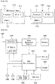
- FIG. 8 shows an example of a reference architecture model for PC5 and LTE-Uu-based V2X to which the disclosure may be applied.
- FIG. 8 shows a non-roaming architecture of a high level for PC5 and LTE-Uu-based V2X communication.
- FIG. 9 shows another example of a reference architecture model for PC5 and LTE-Uu-based V2X to which the disclosure may be applied.
- FIG. 9 shows a roaming architecture of a high level for PC5 and LTE-Uu-based V2X communication.
- a user equipment A (UE A) uses the subscription of a PLMN A
- a user equipment UE B (UE B) uses the subscription of a PLMN B.
- the UE A is roaming in a PLMN C
- the UE B is not roaming.
- a V2X application server may be connected to multiple PLMNs.
- one V2X application server may be connected to the V2X control function of the PLMN A and the V2X control function of the PLMN B.
- FIG. 10 shows yet another example of a reference architecture model for PC5 and LTE-Uu-based V2X to which the disclosure may be applied.
- FIG. 10 shows an inter-PLMN architecture of a high level for PC5 and LTE-Uu-based V2X communication.
- a user equipment A uses the subscription of a PLMN A
- a user equipment B uses the subscription of a PLMN B.
- the UE A is roaming in a PLMN C
- the UE B is not roaming.
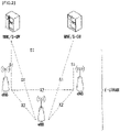
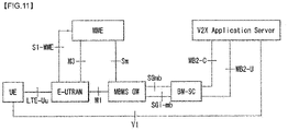
- FIG. 11 shows an example of a multimedia broadcast multicast service (MBMS) reference architecture model for LTE-Uu-based V2X to which the disclosure may be applied.
- MBMS multimedia broadcast multicast service
- FIG. 11 shows an MBMS reference architecture of a high level for LTE-Uu-based V2X communication.
- V2X control function may be defined as a logical function used for network-related tasks necessary for V2X.
- reference points newly defined to perform the V2X control function may be defined as follows:
- V2X message transmission and reception through a PC5 reference point is described.
- the PC5 reference point may be used for the transmission and reception of a V2X message(s).
- V2X communication through the PC5 reference point may support roaming and operations between PLMNs.
- V2X communication through the PC5 reference point is supported in the case where a UE "is served by an E-UTRAN" and the case where a UE "is not served by an E-UTRAN.”
- V2X communication through the PC5 reference point may be a type of Prose Direct communication having the following characteristics.
- V2X message transmission and reception through the LTE-Uu reference point is described.
- the LTE-Uu reference point is used for the transmission and reception of V2X messages.
- V2X message transmission and reception through unicast and V2X reception through an MBMS are described.
- V2X communication through unicast over the LTE-Uu reference point supports a roaming operation.
- a latency reduction of V2X message transmission through unicast may be achieved using SIPTO@LN or SIPTO.
- the existing unicast routing for the V2X application server may be applied.
- the V2X message may be broadcasted through an MBMS.
- the V2X application server transmits the V2X message through MBMS bearer service.
- V2X USD per PLMN for V2X service is necessary for a user equipment.
- the user equipment is provisioned as the mapping of the PSID (or ITS-AID) and the V2X USD.
- the following methods may be used to provide a V2X USD to a user equipment.
- the user equipment may receive downlink broadcast from a PLMN other than a serving PLMN based on an obtained V2X USD(s). Furthermore, an operator may configure a plurality of MBMS service regions for a specific V2X service. If one of the MBMS service regions overlaps, the user equipment may need to configure then overlapped MBMS service region for such a V2X service with a different TMGI.
- the V2X application server that provides V2X service identified by a PSID (or ITS-AID) transmits a V2X message through UDP/IP transmission using information provided by a V2X USD.
- a localized MBMS may be considered for the localized routing of the V2X message toward the user equipment.
- a salutation such as that illustrated in FIG. 12 , may be proposed.
- the UE identifier used for V2X communication is individually managed with respect to the existing 3GPP identity (e.g., by a third party server that is organizationally different like vehicle OEM), and may be referred to as a "pseudonymous mobile subscriber (PMS) ID.”
- the PMSI may be used for V2X LTE attach/V2X communication instead of a 3GPP IMSI.
- FIG. 12 is a diagram illustrating a solution for connection identifier obfuscation for vehicle (V)-UE privacy protection according to an embodiment of the disclosure.
- a UE may request authentication for a V2X operation from a home V2X control function. This may be performed based on a common 3GPP identity and under an agreement with an HSS for UE subscription information.
- MNO mobile network operator
- PCA pseudonym certification authority
- V-OEM original equipment manufacturer
- vehicle UE vehicle UE
- the MNO provides each of its own vehicle UEs with K_PERIOD (the same for all UEs) for encrypting a PMSI in order to hide a PMSI from a third party server.
- K_PERIOD is a cryptographic key shared between the MNO and the V-UE for the protection of (PMSI, K_PMSI) pairs.
- K_PERIOD may be periodically updated and shared by the MNO (if the update cycle of K_PERIOD is very long, there is a danger of damage attributable to the leakage of K_PERIOD. If the update cycle of K_PERIOD is very short, there may be overhead in sharing K_PERIOD).
- a V2X control function may be performed by transmitting a PMSI key shared with each UE when authentication is successful.
- this solution may be performed according to the following step.
- the v-UE has some (PMSI, K_PMSI) pairs used for attach.
- the MNO is aware that the corresponding PMSI is an authorized PMSI, but cannot be aware of the IMSI of the UE.
- the solution proposed in relation to this drawing has been introduced for the purpose of preventing information, such as the moving speed or direction of a vehicle, from being used for another malicious purpose (e.g., a celebrity's vehicle tracking) or a use (e.g., overspeed ticket issue) not wanted by a user not road safety or useful information because the information, such as the moving speed or direction of a vehicle, is exposed in using V2X service.
- Another malicious purpose e.g., a celebrity's vehicle tracking
- a use e.g., overspeed ticket issue
- the solution proposed in FIG. 12 may have a weak point in that the lawful interception (LI) of a lawful investigation purpose cannot be performed according to legal requirements.
- LI lawful interception
- the reason for this is that it is impossible to track a V2X user equipment based on an IMSI, that is, an identifier that may uniquely define an actual service subscriber (e.g., 3GPP communication service subscriber), because the V2X user equipment is indicated based on only a PMSI.
- a core network is configured with a home network and a serving network
- LI needs to be performed in the serving network without the help of the home network.
- a serving network on which the roaming of a user equipment is performed may also be referred to as a visited network, newly serving network or roamed serving network.
- the home network may also be referred to as the home environment of a corresponding V2X UE.
- the disclosure proposes a method of providing LI in a pseudonym system for V2X privacy.
- the method proposed in the disclosure may include a method of performing LI if a user equipment roams onto another country and/or area, that is, if roaming is performed between networks.
- Methods proposed in the disclosure are described based on the case where a main agent that generates an identifier (i.e., ID), a credential and/or a certificate and a main agent that distributes the identifier, credential and/or certificate are the same, but the disclosure is not limited thereto. That is, although the main agent that generates an ID, a credential and/or a certificate and the main agent that distributes the ID, credential and/or certificate are the same are different (if there is a problem in that the main agent that distributes an ID, a credential and/or a certificate can be aware of information on a V-UE entity through conspiracy with another main agent), the solutions proposed in the disclosure may be identically/similarly applied.
- ID i.e., ID
- a credential and/or a certificate and a main agent that distributes the identifier, credential and/or certificate are the same, if there is a problem in that the main agent that distributes an ID, a credential and/or a certificate
- a user equipment having a V2X function (or supporting V2X service) is referred to as a "UE (or V2X UE, v-UE or vehicle-UE)."
- the UE, V2X UE, v-UE or vehicle-UE may correspond to a UE installed in a vehicle or located within a vehicle and having a V2X function, a V2X functionmounted UE carried by a pedestrian, or a road side unit (RSU) having a V2X function.
- RSU road side unit
- a scheme for providing V2X user equipment privacy in V2X service and LI for a V2X pseudonym system may be configured with a combination of at least one of configurations and/or operations that are proposed below.
- roaming methods described through a second embodiment, a third embodiment, and a fourth embodiment may be configured so that they are commonly performed when a V2X user equipment roams (e.g., roaming between communication service providers or roaming between PLMNs (inter-PLMN roaming)). Accordingly, if the target of actual LI is not determined, the roaming methods may be configured so that LI is performed at any time.
- V2X user equipment e.g., roaming between communication service providers or roaming between PLMNs (inter-PLMN roaming)
- the roaming methods may be configured so that LI is performed at any time.
- methods described in the disclosure are described based on an LTE system-based V2X system, but may also be identically/similarly applied to a new RAT (NR) system-based V2X system.
- NR new RAT
- the home network may mean a network with which a subscriber (i.e., user equipment) has been registered.
- the serving network may mean a network on which a subscriber has temporarily performed roaming, and may mean a network that has deviated from a home network boundary.
- an entity (e.g., MME) operating in the home network may be referred to as a home network
- an entity (e.g., MME) operating in the serving network may be referred to as a serving network.
- what a user equipment roams may mean that the user equipment moves from a network with which the user equipment has not been registered, that is, a first network (e.g., home network), to another network, that is, a second network (e.g., serving network) and is supported with service.
- a first network e.g., home network
- a second network e.g., serving network
- a function and/or entity for the MNO and pseudonym CA are the same or similar to that described above, and thus a redundant description thereof is omitted.
- a PMSI, a ticket, K_PERIOD, etc. described in the embodiments of the disclosure may be the same or similar to those described above, and thus a detailed description thereof is omitted. That is, a PMSI may mean a user equipment identifier used for V2X communication instead of an IMSI. Furthermore, a ticket may mean a different false name or certificate used instead of an IMSI/IMEI when a user equipment requests an encrypted PMSI subpool from a PCA. Furthermore, K_PERIOD may mean a cryptographic key shared between an MNO and a V2X UE shared for the protection of (PMSI, K_PMSI) pairs.
- FIG. 13 shows an example of a procedure for supporting lawful interception according to an embodiment proposed in the disclosure.
- FIG. 13 is merely for convenience of description, and does not restrict the disclosure.
- a lawful enforcement agency may mean an organization that performs an authorized procedure for LI.
- the LEA may include an entity, a user equipment, a server, etc. that performs LI.
- an LI procedure performed between the MNO, the PCA and the LEA may be performed according to the following steps.
- the V2X UE updates the ticket and the PMSI subpool. Accordingly, the LEA needs to repeatedly perform the above-described procedures during the period (or cycle) of LI.
- the LEA of a home network can perform an LI procedure on a target V2X UE (or target IMSI). That is, there is an advantage in that LI can be performed while protecting privacy, such as identification information of a user equipment, such as an IMSI.
- a V2X UE may transmit its own identification information, that is, an IMSI value, to a network (e.g., MME) through a radio interface.
- a network e.g., MME
- the radio interface may mean a wireless communication path.
- the V2X UE may request, from the serving network (i.e., newly serving network) and an affiliated PCA, information on a ticket and a PMSI subpool.
- the V2X UE may obtain information on a ticket and information on a PMSI subpool from the MNO and PCA of the serving network.
- an LEA located in an area supported by the serving network may perform LI as in a home network. That is, the LEA may perform an LI procedure without the help of a home network although a V2X UE is located in the serving network.
- the IMSI of a V2X UE may be transmitted through a radio interface when the V2X UE performs handover or a roaming procedure to a serving network. That is, when the V2X UE performs an additional procedure on the serving network directly using identification information, the identification information of the V2X UE may be exposed to a radio interface. In this case, as described above, information, such as the moving speed, direction, etc. of the V2X UE, may be exposed. The corresponding information may be used for a malicious purpose.
- the ticket in order to prevent the use of an IMSI, a method of using a ticket may be considered.
- the ticket may be the same or similar to the above-described ticket (e.g., the ticket in FIG. 12 ), and may have a form such as a false name or a certificate.
- a ticket provided by a home network for a PMSI subpool(s) may be referred to as a V2X ticket.
- a serving network may also be referred to as a visited network.
- the V2X UE may transmit, to a serving network (e.g., the MME of the serving network), the V2X ticket instead of a GUTI or an IMSI. That is, the V2X UE may transmit, to the serving network, the ticket (previously) provided by the home network (e.g., the MME of the home network in order to request the issue of a new ticket from the serving network.
- a serving network e.g., the MME of the serving network
- the V2X ticket instead of a GUTI or an IMSI. That is, the V2X UE may transmit, to the serving network, the ticket (previously) provided by the home network (e.g., the MME of the home network in order to request the issue of a new ticket from the serving network.
- the new ticket may mean a ticket used by the V2X UE to protect identification information (e.g., IMSI) of the corresponding V2X UE in the serving network. That is, the new ticket means a ticket required for the V2X UE to request information on a PMSI subpool from a PCA affiliated with the serving network, and may also be referred to as a new V2X ticket.
- identification information e.g., IMSI
- the request includes information (home network information) on the home network (e.g., identification information of the MME of the home network).
- the home network that has received such a request from the serving network may discover (or identify) an IMSI(s) for the corresponding V2X ticket.
- the home network may respond (or deliver) the discovered IMSI and authentication data to the serving network.
- the serving network may provide the V2X UE with a new V2X ticket. That is, the serving network may transmit, to the V2X UE, a new V2X ticket determined (or selected) based on the IMSI received from the home network. In this case, the corresponding V2X UE may request information on the PMSI subpool from the PCA of the serving network.
- An LEA located in the serving network may perform LI on the target V2X UE, as in the home network, based on the PMSI(s) and ticket obtained based on the above-described procedures. That is, the LEA may perform an LI procedure without the help of a home network although the V2X UE is located in the serving network.
- FIG. 14 shows another example of a procedure for supporting LI according to an embodiment proposed in the disclosure.
- FIG. 14 is merely for convenience of description, and does not restrict the scope of the disclosure.
- the home network 1406 may mean an MME supporting the home network
- the serving network 1404 may mean an MME (e.g., (newly) visited MME) supporting the serving network.
- the V2X UE may request a new V2X ticket from the serving network.
- the V2X UE may transmit, to the serving network, a V2X ticket used in the home network.
- the corresponding V2X ticket may be encrypted using K_PERIOD_OLD.
- K_PERIOD_OLD may mean K_PERIOD given (or used) in the home network of the V2X UE prior to roaming.
- the request at step S1405 may be a request toward the home network.
- the corresponding request may include information (e.g., mobile country code (MCC), mobile network code (MNC), public land mobile network (PLMN)) of the home network. That is, the corresponding request may include identification information or operator identification information for the home network.
- MCC mobile country code
- MNC mobile network code
- PLMN public land mobile network
- the serving network may transmit the received V2X ticket to the home network.
- V2X roaming agreement i.e., V2X roaming agreement has been made
- the home network may confirm subscription information of the V2X UE using the received V2X ticket.
- the home network may decrypt (or recover) the encrypted V2X ticket using K_PERIOD_OLD.
- the home network may first confirm the validity of the V2X ticket before confirming the subscription information.
- the home network may transmit, to the serving network, IMSI information of the corresponding V2X UE based on the subscription information confirmed with respect to the V2X UE.
- the home network may transmit authentication data for the corresponding user equipment in addition to the IMSI information.
- the serving network may obtain the IMSI information of the corresponding V2X UE without a transmission procedure on a radio interface.
- the serving network may transmit a new V2X ticket and K_PERIOD to the V2X UE.
- K_PERIOD may mean a cryptographic key shared between an entity(s) of the serving network and the V2X UE for the protection of (PMSI, K_PMSI) pairs.
- V2X ticket i.e., V2X ticket, new V2X ticket
- a danger of a loss of a ticket attributable to a fake serving network can be prevented.
- the V2X user equipment may request information on a PMSI subpool(s) from the PCA of a visited area using the new V2X ticket received at step S1425.
- the visited area may mean an area in which service by the serving network that the user equipment has roamed is supported.
- the LEA may perform, even in the visited area, an LI procedure of requesting the PMSI subpool(s) and ticket of a target V2X UE having an IMSI, as in the home network, without the support of the home network for a V2X UE. That is, after the procedures described in the present embodiment are performed, an LI procedure (e.g., the procedure described in the first embodiment) in the serving network may be configured to be performed.
- an LI procedure e.g., the procedure described in the first embodiment
- a network that has made a roaming agreement may accommodate a PMSI(s) from a plurality of PCAs.
- a V2X UE may request a new PMSI(s) from a newly serving network and a PCA affiliated with the newly serving network.
- an LI procedure in a serving network can be performed as in a home network and the IMSI of a V2X UE can be prevented from being transmitted on a radio interface in order to be provided with V2X service.
- a configuration method of encrypting the V2X ticket using a specific cryptographic key e.g., K_PERIOD_OLD
- decoding and using the V2X ticket in a home network may be considered.
- a serving network may be configured to additionally perform a procedure of comparing an IMSI, received from a V2X UE, with an IMSI received from a home network.
- An example considered in such a procedure may be the same as FIG. 15 .
- FIG. 15 shows yet another example of a procedure for LI according to an embodiment proposed in the disclosure.
- FIG. 15 is merely for convenience of description, and does not restrict the scope of the disclosure.
- the home network 1506 may mean an MME supporting the home network
- the serving network 1501 may mean an MME (e.g., (newly) visited MME) supporting the serving network.
- steps in FIG. 15 may be the same or similar to the steps described in FIG. 14 .
- steps added or changed compared to the steps of FIG. 14 in order for the serving network to confirm an IMSI correspond to steps S1520, S1525, S1530, S1535 and S1540.
- steps S1505 to S1515 are the same or similar to steps S1405 to S1415 in FIG. 14
- step S1425 step is the same or similar to step S1545, and a redundant description is omitted.
- the home network that has received the V2X ticket of the V2X UE through steps S1505 to S1515 may transmit the IMSI of the V2X UE, K_VISITED and/or encrypted K_VISITED to the serving network.
- K_VISITED may mean a cryptographic key for confirming an IMSI between the V2X UE and the serving network.
- K_VISITED is a symmetric cryptographic key generated by the home network of the V2X UE, and may be distributed to the V2X UE and the serving network.
- the encrypted K_VISITED may mean K_VISITED encrypted using K_PERIOD_OLD (or a cryptographic key shared by the V2X UE and the home network).
- the serving network may transmit the encrypted K_VISITED to the V2X UE.
- the V2X UE may decrypt the encrypted K_VISITED using K_PERIOD_OLD (or the cryptographic key shared by the V2X UE and the home network). In this case, a case where K_PERIOD_OLD has been shared between the home network and the V2X UE is assumed. Thereafter, at step S1535, the V2X UE may encrypt an IMSI using the decrypted and obtained K_VISITED, and may transmit the encrypted IMSI to the serving network.
- K_PERIOD_OLD or the cryptographic key shared by the V2X UE and the home network.
- the serving network may determine whether the IMSI received from the home network (i.e., IMSI received at step S1520) is the same as the IMSI received from the V2X UE (i.e., IMSI received at step S1535) by comparing the IMSI received from the home network with the IMSI received from the V2X UE.
- the serving network may decrypt the encrypted IMSI, received from the V2X UE, using K_VISITED, and may compare the IMSI received from the home network with the IMSI received from the V2X UE.
- the serving network may transmit a new V2X ticket and K_PERIOD to the V2X UE.
- the serving network may not transmit a new V2X ticket and K_PERIOD, and may request the retransmission of an IMSI from the V2X UE and/or the home network.
- the V2X user equipment may request information on a PMSI subpool(s) from the PCA of a visited area.
- the LEA may perform, even in the visited area, an LI procedure of requesting a PMSI subpool(s) and ticket of a target V2X UE having an IMSI without the support of a home network for the V2X UE.
- a serving network may determine whether IMSIs received from a home network and a V2X UE are accurate information and reliability and accuracy of an LI procedure to be performed in a serving network can be improved.
- FIG. 16 shows an example of a flowchart for a method of preventing the exposure of the identifier of a user equipment and supporting an LI procedure according to an embodiment of the disclosure.
- FIG. 16 is merely for convenience of description, and does not restrict the scope of the disclosure.
- the identifier of a user equipment may indicate a PMSI assigned to a corresponding user equipment for V2X communication network access.
- Identification information of the user equipment may indicate an IMSI, that is, a unique identifier of a corresponding user equipment.
- this flowchart may be an operational flowchart in a serving network, that is, the MME of a serving network, in the above-described embodiments.
- the MME of the serving network may receive, from the user equipment, a message to request a first ticket that authenticates access authorization for an identifier in the serving network of the user equipment.
- the corresponding message may include information on a second ticket that authenticates access authorization for the identifier in the home network of the user equipment.
- the first ticket and the second ticket may correspond to the new V2X ticket and V2X ticket in the third embodiment and the fourth embodiment, respectively.
- the information on the second ticket may be encrypted using a temporary key (e.g., the above-described K_PERIOD_OLD) used to encrypt the identifier in the home network.
- a temporary key e.g., the above-described K_PERIOD_OLD
- the corresponding message may further include operator identification information for the home network.
- the MME of the serving network may transmit the received information on the second ticket to the MME of the home network. Accordingly, the MME of the home network may confirm (or identify) subscription information, that is, identification information for the corresponding V2X UE.
- the MME of the serving network may receive identification information of the user equipment determined based on the information on the second ticket received from the MME of the home network.
- a specific cryptographic key e.g., the above-described K_VISITED
- a specific cryptographic key e.g., the above-described encrypted K_VISITED
- a specific cryptographic key i.e., a specific cryptographic key
- the MME of the serving network may receive, from the MME of the home network, the specific cryptographic key and information (i.e., specific cryptographic key information) of the specific cryptographic key encrypted using the temporary key used to encrypt the identifier in the home network. Thereafter, the MME of the serving network may transmit, to the user equipment, the specific cryptographic key information, and may receive, from the user equipment, the identification information of the user equipment encrypted using the specific cryptographic key. Thereafter, the MME of the serving network may determine whether the identification information received from the user equipment and the identification information received from the MME of the home network are the same. A detailed description related to this is the same as that described in relation to FIG. 15 .
- the MME of the serving network may transmit, to the user equipment, information on the first ticket and a temporary key used to encrypt the identifier in the serving network based on the received identification information.
- the user equipment or the LEA of the serving network may request a subpool (e.g., PMSI subpool) for the identifier of the user equipment from the PCA of the serving network using the first ticket and the temporary key. That is, the above-described lawful interception procedure (e.g., the procedure described in FIG. 13 ) may be performed in the serving network without the help of a home network.
- the LEA may be an entity that performs lawful interception on the user equipment based on the identifier of the corresponding user equipment in the serving network, which has been obtained using the first ticket and the temporary key.
- FIG. 17 illustrates a block diagram of a communication apparatus according to an embodiment of the disclosure.
- a wireless communication system includes a network node 1710 and multiple user equipments 1720.
- the network node 1710 includes a processor 1711, a memory 1712, and a communication module 1713.
- the processor 1711 implements a function, a process and/or a method proposed in FIGS. 1 to 16 .
- the layers of a wired/wireless interface protocol may be implemented by the processor 1711.
- the memory 1712 is connected to the processor 1711 and stores various pieces of information for driving the processor 1711.
- the communication module 1713 is connected to the processor 1711 and transmits and/or receives a radio signal.
- An example of the network node 1710 may correspond to a base station, MME, HSS, SGW, PGW, SCEF, SCS/AS, etc.
- the communication module 1713 may include a radio frequency (RF) unit for transmitting/receiving a radio signal.
- RF radio frequency
- the UE 1720 includes a processor 1721, a memory 1722, and a communication module (or RF unit) 1723.
- the processor 1721 implements a function, a process and/or a method proposed in FIGS. 1 to 15 .
- the layers of a wireless interface protocol may be implemented by the processor 1721.
- the memory 1722 is connected to the processor 1721 and stores various pieces of information for driving the processor 1721.
- the communication module 1723 is connected to the processor 1721 and transmits and/or receives a radio signal.
- the memories 1712 and 1722 may be positioned inside or outside the processors 1711 and 1721 and connected to the processors 1711 and 1721 by various well-known means. Further, the network node 1710 (if the network node 1710 is a base station) and/or the UE 1720 may have a single antenna or multiple antennas.
- FIG. 18 illustrates a block diagram of a communication apparatus according to an embodiment of the disclosure.
- FIG. 18 is a diagram more specifically illustrating the UE of FIG. 16 above.
- the UE may be configured to include a processor (or a digital signal processor (DSP)) 1810, a radio frequency module (or RF unit) 1835, a power management module 1805, an antenna 1840, a battery 1855, a display 1815, a keypad 1820, a memory 1830, a subscriber identification module (SIM) card 1825 (this is optional), a speaker 1845, and a microphone 1850.
- the UE may also include a single antenna or multiple antennas.
- the processor 1810 implements a function, a process, and/or a method proposed in FIGS. 1 to 16 .
- the layers of a wireless interface protocol may be implemented by the processor 1810.
- the memory 1830 is connected to the processor 1810 and stores information related to an operation of the processor 1810.
- the memory 1830 may be positioned inside or outside the processor 1810 and connected to the processor 1810 by various well-known means.
- a user inputs command information, such as a telephone number by pressing (or touching) a button on the keypad 1820 or by voice activation using the microphone 1850, for example.
- the processor 1810 receives such command information and processes to perform appropriate functions including dialing a telephone number. Operational data may be extracted from the SIM card 1825 or the memory 1830. In addition, the processor 1810 may display command information or drive information on the display 1815 for the user to recognize and for convenience.
- the RF module 1835 is connected to the processor 1810 to transmit and/or receive an RF signal.
- the processor 1810 transfers the command information to the RF module 1835 to initiate communication, for example, to transmit radio signals constituting voice communication data.
- the RF module 1835 is constituted by a receiver and a transmitter for receiving and transmitting the radio signals.
- the antenna 1840 functions to transmit and receive the radio signals.
- the RF module 1835 may transfer the signal for processing by the processor 1810 and convert the signal to a baseband.
- the processed signal may be converted into to audible or readable information output via the speaker 1845.
- the embodiments of the disclosure may be achieved by various means, for example, hardware, firmware, software, or a combination thereof.
- the methods according to the embodiments of the disclosure may be achieved by one or more ASICs (Application Specific Integrated Circuits), DSPs (Digital Signal Processors), DSPDs (Digital Signal Processing Devices), PLDs (Programmable Logic Devices), FPGAs (Field Programmable Gate Arrays), processors, controllers, microcontrollers, microprocessors, etc.
- ASICs Application Specific Integrated Circuits
- DSPs Digital Signal Processors
- DSPDs Digital Signal Processing Devices
- PLDs Programmable Logic Devices
- FPGAs Field Programmable Gate Arrays
- processors controllers, microcontrollers, microprocessors, etc.
- the embodiments of the disclosure may be implemented in the form of a module, a procedure, a function, etc.
- Software code may be stored in the memory and executed by the processor.
- the memory may be located at the interior or exterior of the processor and may transmit data to and receive data from the processor via various known means.
- the disclosure is applied to a 3GPP LTE/LTE-A system is primarily described, but can be applied to various wireless communication systems such as New RAT (NR) system in addition to the 3GPP LTE/LTE-A system.
- NR New RAT
Landscapes
- Engineering & Computer Science (AREA)
- Computer Networks & Wireless Communication (AREA)
- Signal Processing (AREA)
- Computer Security & Cryptography (AREA)
- Databases & Information Systems (AREA)
- Technology Law (AREA)
- Mobile Radio Communication Systems (AREA)
Claims (9)
- Verfahren zur Sicherung einer pseudonymen mobilen Teilnehmer-ID, PMSI, eines Fahrzeug-zu-Allem-, V2X, Benutzergeräts, das beim Zugriff auf ein Netzwerk in einem Drahtloskommunikationssystem verwendet wird, wobei die PMSI einem entsprechenden Benutzergerät für V2X-Kommunikationsnetzwerkzugriff zugewiesen wird, wobei das Verfahren umfasst:Empfangen (S1605) einer Nachricht von dem V2X-Benutzergerät zum Anfordern eines ersten V2X-Tickets, das die Zugriffsautorisierung für die Kennung in einem bedienenden Netzwerk des V2X-Benutzergeräts authentifiziert, wobei die Nachricht Informationen über ein zweites V2X-Ticket zum Authentifizieren der Zugriffsautorisierung für die PMSI in einem Heimnetzwerk des V2X-Benutzergeräts umfasst,Senden (S1610) der Informationen über das zweite V2X-Ticket an eine Mobilitätsverwaltungsentität, MME, des Heimnetzwerks,Empfangen (S1615) einer internationalen Mobilfunkteilnehmerkennung, IMSI, des basierend auf den Informationen über das zweite V2X-Ticket bestimmten V2X-Benutzergeräts von der MME des Heimnetzwerks,Bestätigen einer Gültigkeit der IMSI unter Verwendung eines spezifischen kryptographischen Schlüssels, der zum Bestätigen der Gültigkeit der IMSI verwendet wird, undSenden (S1620) des ersten V2X-Tickets und von Informationen über einen temporären Schlüssel, der zum Verschlüsseln der PMSI in dem bedienenden Netzwerk basierend auf der IMSI verwendet wird, an das V2X-Benutzergerät,wobei das Bestätigen der Gültigkeit der IMSI umfasst:Empfangen des spezifischen kryptografischen Schlüssels und spezifischer kryptografischer Schlüsselinformationen, die von dem spezifischen kryptografischen Schlüssel unter Verwendung eines temporären Schlüssels verschlüsselt werden, der zum Verschlüsseln der PMSI in dem Heimnetzwerk verwendet wird, von der MME des Heimnetzwerks,Senden der spezifischen kryptografischen Schlüsselinformationen an das V2X-Benutzergerät,Empfangen der IMSI des V2X-Benutzergeräts, die unter Verwendung des spezifischen kryptografischen Schlüssels verschlüsselt wird, von dem V2X-Benutzergerät undBestätigen, ob die IMSI des V2X-Benutzergeräts, die von dem V2X-Benutzergerät empfangen wird, identisch mit der IMSI des V2X-Benutzergeräts ist, die von der MME des Heimnetzwerks empfangen wird.
- Verfahren nach Anspruch 1,
wobei die Nachricht ferner eine Betreiber-IMSI für das Heimnetzwerk umfasst. - Verfahren nach Anspruch 1,
wobei die Informationen über das zweite V2X-Ticket unter Verwendung eines temporären Schlüssels verschlüsselt werden, der zum Verschlüsseln der PMSI in dem Heimnetzwerk verwendet wird. - Verfahren nach Anspruch 1, ferner umfassend:
Senden einer Nachricht zum Anfordern einer erneuten Übertragung der IMSI des V2X-Benutzergeräts, wenn die von dem V2X-Benutzergerät empfangene IMSI des V2X-Benutzergeräts nicht identisch mit der von der MME des Heimnetzwerks empfangenen IMSI des V2X-Benutzergeräts ist, an zumindest eines von dem V2X-Benutzergerät oder der MME des Heimnetzwerks. - Verfahren nach Anspruch 1,
wobei der spezifische kryptografische Schlüssel durch das Heimnetzwerk erzeugt wird. - Verfahren nach Anspruch 1,
wobei das bedienende Netzwerk ein Netzwerk ist, das von dem V2X-Benutzergerät von dem Heimnetzwerk durchwandert wird. - Verfahren nach Anspruch 1,
wobei das erste V2X-Ticket und die Informationen über den temporären Schlüssel Informationen sind, die für das V2X-Benutzergerät oder eine Rechtsdurchsetzungsbehörde, LEA, des bedienenden Netzwerks verwendet werden, um einen Unterpool für die PMSI von einer Pseudonym-Zertifizierungsstelle, PCA, des bedienenden Netzwerks anzufordern. - Verfahren nach Anspruch 7,
wobei die LEA des bedienenden Netzwerks eine Entität ist, die ein rechtmäßiges Abhören, LI, auf dem V2X-Benutzergerät basierend auf der PMSI des V2X-Benutzergeräts durchführt, die unter Verwendung des ersten V2X-Tickets und des temporären Schlüssels in dem bedienenden Netzwerk erhalten wurde. - Bedienendes Netzwerk zum Schützen einer pseudonymen mobilen Teilnehmer-ID, PMSI, eines Fahrzeug-zu-Allem-, V2X, Benutzergeräts (1720), das beim Zugriff auf ein Netzwerk in einem Drahtloskommunikationssystem verwendet wird, wobei die PMSI einem entsprechenden Benutzergerät für V2X-Kommunikationsnetzwerkzugriff zugewiesen wird, wobei das bedienende Netzwerk umfasst:
einen Transceiver (1713) zum Senden und Empfangen von Signalen und einen Prozessor (1711), der eingerichtet ist, um den Transceiver (1713) zu steuern, wobei der Prozessor (1711) eingerichtet ist zum:Empfangen (S1605) einer Nachricht von dem V2X-Benutzergerät (1720) zum Anfordern eines ersten V2X-Tickets, das die Zugriffsautorisierung für die Kennung in dem bedienenden Netzwerk des V2X-Benutzergeräts (1720) authentifiziert, wobei die Nachricht Informationen über ein zweites V2X-Ticket zum Authentifizieren der Zugriffsautorisierung für die PMSI in einem Heimnetzwerk des V2X-Benutzergeräts (1720) umfasst,Senden (S1610) der Informationen über das zweite V2X-Ticket an eine Mobilitätsverwaltungsentität, MME, des Heimnetzwerks,Empfangen (S1615) einer internationalen Mobilfunkteilnehmerkennung, IMSI, des basierend auf den Informationen über das zweite V2X-Ticket bestimmten V2X-Benutzergeräts von der MME des Heimnetzwerks, undSenden (S1620) des ersten V2X-Tickets und von Informationen über einen temporären Schlüssel, der zum Verschlüsseln der PMSI in dem bedienenden Netzwerk basierend auf der IMSI verwendet wird, an das V2X-Benutzergerät (1720),wobei der Prozessor ferner eingerichtet ist zum:Bestätigen einer Gültigkeit der IMSI unter Verwendung eines spezifischen kryptografischen Schlüssels, der zum Bestätigen der Gültigkeit der IMSI verwendet wird,wobei das Bestätigen der Gültigkeit der IMSI umfasst:Empfangen des spezifischen kryptografischen Schlüssels und spezifischer kryptografischer Schlüsselinformationen, die durch Verschlüsseln des spezifischen kryptografischen Schlüssels unter Verwendung eines temporären Schlüssels erhalten wird, der zum Verschlüsseln der PMSI in dem Heimnetzwerk verwendet wird, von der MME des Heimnetzwerks,Senden der spezifischen kryptografischen Schlüsselinformationen an das V2X-Benutzergerät,Empfangen der IMSI des V2X-Benutzergeräts, die unter Verwendung des spezifischen kryptografischen Schlüssels verschlüsselt wird, von dem V2X-Benutzergerät undBestätigen, ob die IMSI des V2X-Benutzergeräts, die von dem V2X-Benutzergerät empfangen wird, identisch mit der IMSI des V2X-Benutzergeräts ist, die von der MME des Heimnetzwerks empfangen wird.
Applications Claiming Priority (2)
| Application Number | Priority Date | Filing Date | Title |
|---|---|---|---|
| US201762502788P | 2017-05-08 | 2017-05-08 | |
| PCT/KR2018/005275 WO2018208062A1 (ko) | 2017-05-08 | 2018-05-08 | 무선 통신 시스템에서의 단말의 접속 식별자 보안 방법 및 이를 위한 장치 |
Publications (3)
| Publication Number | Publication Date |
|---|---|
| EP3624476A1 EP3624476A1 (de) | 2020-03-18 |
| EP3624476A4 EP3624476A4 (de) | 2021-01-20 |
| EP3624476B1 true EP3624476B1 (de) | 2022-07-06 |
Family
ID=64105448
Family Applications (1)
| Application Number | Title | Priority Date | Filing Date |
|---|---|---|---|
| EP18799243.3A Active EP3624476B1 (de) | 2017-05-08 | 2018-05-08 | Verfahren zur sicherung eines übertragungsidentifikators eines benutzergeräts in einem drahtloskommunikationssystem und vorrichtung dafür |
Country Status (3)
| Country | Link |
|---|---|
| US (1) | US10979904B2 (de) |
| EP (1) | EP3624476B1 (de) |
| WO (1) | WO2018208062A1 (de) |
Families Citing this family (11)
| Publication number | Priority date | Publication date | Assignee | Title |
|---|---|---|---|---|
| WO2014031689A1 (en) | 2012-08-24 | 2014-02-27 | Oceus Networks Inc. | Mobile cellular networks |
| WO2014031597A1 (en) | 2012-08-24 | 2014-02-27 | Oceus Networks Inc. | Mobile cellular networks |
| WO2014179235A1 (en) | 2013-04-29 | 2014-11-06 | Oceus Networks Inc. | Mobile cellular network backhaul |
| US10873891B2 (en) | 2016-07-06 | 2020-12-22 | Oceus Networks, Llc | Secure network rollover |
| US9686238B1 (en) * | 2016-07-07 | 2017-06-20 | Oceus Networks Inc. | Secure network enrollment |
| US10172078B2 (en) | 2017-03-31 | 2019-01-01 | Oceus Networks Inc. | Targeted user equipment-base station communication link |
| CN109246688B (zh) | 2017-07-11 | 2021-02-23 | 华为技术有限公司 | 设备接入方法、设备及系统 |
| CN109727354A (zh) * | 2018-12-27 | 2019-05-07 | 北京摩拜科技有限公司 | 一种车辆的控制方法和系统 |
| WO2021000322A1 (en) * | 2019-07-04 | 2021-01-07 | Nokia Shanghai Bell Co., Ltd. | Proactive switching of v2x communication from sidelink connection to cellular connection |
| US11956627B2 (en) * | 2021-02-19 | 2024-04-09 | Nokia Technologies Oy | Securing user equipment identifier for use external to communication network |
| WO2023147767A1 (zh) * | 2022-02-07 | 2023-08-10 | 华为技术有限公司 | 网络校验的方法和装置 |
Family Cites Families (7)
| Publication number | Priority date | Publication date | Assignee | Title |
|---|---|---|---|---|
| US8347090B2 (en) * | 2006-10-16 | 2013-01-01 | Nokia Corporation | Encryption of identifiers in a communication system |
| EP2704484B1 (de) * | 2012-09-03 | 2021-01-20 | Mitsubishi Electric R&D Centre Europe B.V. | Verfahren zur Durchführung einer Übergabe mittels Autorisierungstickets |
| US9055520B2 (en) * | 2012-12-19 | 2015-06-09 | Cisco Technology, Inc. | Systems, methods and media for mobile management entity (MME) selection by Evolved Node B (eNodeB) |
| KR20150006332A (ko) * | 2013-07-08 | 2015-01-16 | 삼성전자주식회사 | 단말 대 단말 통신을 지원하는 단말에 대한 합법적 감청 방법 및 장치 |
| KR102265658B1 (ko) * | 2014-07-23 | 2021-06-17 | 삼성전자주식회사 | 전자장치 및 전자장치의 네트워크 검색방법 |
| US10237729B2 (en) | 2015-03-05 | 2019-03-19 | Qualcomm Incorporated | Identity privacy in wireless networks |
| US10492065B2 (en) * | 2017-06-23 | 2019-11-26 | Bank Of America Corporation | Encryption system and method |
-
2018
- 2018-05-08 EP EP18799243.3A patent/EP3624476B1/de active Active
- 2018-05-08 US US16/611,424 patent/US10979904B2/en active Active
- 2018-05-08 WO PCT/KR2018/005275 patent/WO2018208062A1/ko unknown
Also Published As
| Publication number | Publication date |
|---|---|
| US10979904B2 (en) | 2021-04-13 |
| EP3624476A4 (de) | 2021-01-20 |
| US20200169877A1 (en) | 2020-05-28 |
| EP3624476A1 (de) | 2020-03-18 |
| WO2018208062A1 (ko) | 2018-11-15 |
Similar Documents
| Publication | Publication Date | Title |
|---|---|---|
| EP3624476B1 (de) | Verfahren zur sicherung eines übertragungsidentifikators eines benutzergeräts in einem drahtloskommunikationssystem und vorrichtung dafür | |
| US10548005B2 (en) | Method for security of user equipment connection identifier in wireless communication system and apparatus therefor | |
| CN110447250B (zh) | 用于无线通信系统中层之间交互的方法及其设备 | |
| EP3641424B1 (de) | Verfahren zur registrierung eines benutzergeräts in einer netzwerkscheibe in einem drahtlosen kommunikationssystem und benutzergerät dafür | |
| US10652085B2 (en) | Method for setting configuration of non-IP data delivery (NDID) in wireless communication system and device for same | |
| US10624004B2 (en) | Serving node relocating method in wireless communication system and device for same | |
| CN110402604B (zh) | 在无线通信系统中通知移动性事件的方法及其设备 | |
| US10674469B2 (en) | Method for performing service request procedure and apparatus therefor in wireless communication system | |
| EP3435696B1 (de) | Verfahren zur verfolgung einer bereichsaktualisierung in einem drahtloskommunikationssystem und vorrichtung dafür | |
| US10687175B2 (en) | Method for transmitting and receiving V2X message in wireless communication system, and an apparatus for same | |
| US10602380B2 (en) | Method for selecting data transmission mode in wireless communication system and apparatus therefor | |
| US20200178048A1 (en) | V2x communication support method in wireless communication system | |
| JP2019534653A (ja) | 無線通信システムにおけるネットワークノード選択方法及びその装置 | |
| KR102104591B1 (ko) | 무선 통신 시스템에서 차량 ue 및 rsu ue를 인증하기 위한 방법 및 장치 | |
| EP3425993B1 (de) | Verfahren zur verbindungsverwaltung eines benutzergeräts zum senden und empfangen einer v2x-nachricht in einem drahtloskommunikationssystem und vorrichtung dafür | |
| EP3637890B1 (de) | Verfahren zur durchführung von v2x-kommunikation in einem drahtloskommunikationssystem und vorrichtung dafür |
Legal Events
| Date | Code | Title | Description |
|---|---|---|---|
| STAA | Information on the status of an ep patent application or granted ep patent |
Free format text: STATUS: THE INTERNATIONAL PUBLICATION HAS BEEN MADE |
|
| PUAI | Public reference made under article 153(3) epc to a published international application that has entered the european phase |
Free format text: ORIGINAL CODE: 0009012 |
|
| STAA | Information on the status of an ep patent application or granted ep patent |
Free format text: STATUS: REQUEST FOR EXAMINATION WAS MADE |
|
| 17P | Request for examination filed |
Effective date: 20191204 |
|
| AK | Designated contracting states |
Kind code of ref document: A1 Designated state(s): AL AT BE BG CH CY CZ DE DK EE ES FI FR GB GR HR HU IE IS IT LI LT LU LV MC MK MT NL NO PL PT RO RS SE SI SK SM TR |
|
| AX | Request for extension of the european patent |
Extension state: BA ME |
|
| DAV | Request for validation of the european patent (deleted) | ||
| DAX | Request for extension of the european patent (deleted) | ||
| A4 | Supplementary search report drawn up and despatched |
Effective date: 20201218 |
|
| RIC1 | Information provided on ipc code assigned before grant |
Ipc: H04W 12/06 20090101ALI20201214BHEP Ipc: H04L 29/08 20060101ALN20201214BHEP Ipc: H04W 12/08 20090101AFI20201214BHEP Ipc: H04W 12/00 20090101ALI20201214BHEP Ipc: H04W 12/04 20090101ALI20201214BHEP Ipc: H04L 29/06 20060101ALI20201214BHEP Ipc: H04W 12/02 20090101ALN20201214BHEP |
|
| STAA | Information on the status of an ep patent application or granted ep patent |
Free format text: STATUS: EXAMINATION IS IN PROGRESS |
|
| 17Q | First examination report despatched |
Effective date: 20210816 |
|
| REG | Reference to a national code |
Ref country code: DE Ref legal event code: R079 Ref document number: 602018037665 Country of ref document: DE Free format text: PREVIOUS MAIN CLASS: H04W0012080000 Ipc: H04W0012030000 |
|
| RIC1 | Information provided on ipc code assigned before grant |
Ipc: H04W 12/61 20210101ALN20211223BHEP Ipc: H04W 8/26 20090101ALN20211223BHEP Ipc: H04W 60/04 20090101ALN20211223BHEP Ipc: H04W 8/20 20090101ALN20211223BHEP Ipc: H04W 12/75 20210101ALN20211223BHEP Ipc: H04W 8/02 20090101ALN20211223BHEP Ipc: H04L 29/06 20060101ALN20211223BHEP Ipc: H04W 12/02 20090101ALN20211223BHEP Ipc: H04W 12/00 20210101ALN20211223BHEP Ipc: H04W 4/44 20180101ALN20211223BHEP Ipc: H04L 29/08 20060101ALN20211223BHEP Ipc: H04W 12/80 20210101ALI20211223BHEP Ipc: H04W 12/069 20210101ALI20211223BHEP Ipc: H04W 12/0431 20210101ALI20211223BHEP Ipc: H04W 12/03 20210101AFI20211223BHEP |
|
| GRAP | Despatch of communication of intention to grant a patent |
Free format text: ORIGINAL CODE: EPIDOSNIGR1 |
|
| STAA | Information on the status of an ep patent application or granted ep patent |
Free format text: STATUS: GRANT OF PATENT IS INTENDED |
|
| INTG | Intention to grant announced |
Effective date: 20220128 |
|
| RIC1 | Information provided on ipc code assigned before grant |
Ipc: H04L 67/12 20220101ALN20220120BHEP Ipc: H04L 9/40 20220101ALN20220120BHEP Ipc: H04W 12/61 20210101ALN20220120BHEP Ipc: H04W 8/26 20090101ALN20220120BHEP Ipc: H04W 60/04 20090101ALN20220120BHEP Ipc: H04W 8/20 20090101ALN20220120BHEP Ipc: H04W 12/75 20210101ALN20220120BHEP Ipc: H04W 8/02 20090101ALN20220120BHEP Ipc: H04W 12/02 20090101ALN20220120BHEP Ipc: H04W 12/00 20090101ALN20220120BHEP Ipc: H04W 4/44 20180101ALN20220120BHEP Ipc: H04W 12/80 20210101ALI20220120BHEP Ipc: H04W 12/069 20210101ALI20220120BHEP Ipc: H04W 12/0431 20210101ALI20220120BHEP Ipc: H04W 12/03 20210101AFI20220120BHEP |
|
| GRAS | Grant fee paid |
Free format text: ORIGINAL CODE: EPIDOSNIGR3 |
|
| GRAA | (expected) grant |
Free format text: ORIGINAL CODE: 0009210 |
|
| STAA | Information on the status of an ep patent application or granted ep patent |
Free format text: STATUS: THE PATENT HAS BEEN GRANTED |
|
| AK | Designated contracting states |
Kind code of ref document: B1 Designated state(s): AL AT BE BG CH CY CZ DE DK EE ES FI FR GB GR HR HU IE IS IT LI LT LU LV MC MK MT NL NO PL PT RO RS SE SI SK SM TR |
|
| REG | Reference to a national code |
Ref country code: AT Ref legal event code: REF Ref document number: 1503742 Country of ref document: AT Kind code of ref document: T Effective date: 20220715 Ref country code: CH Ref legal event code: EP |
|
| REG | Reference to a national code |
Ref country code: DE Ref legal event code: R096 Ref document number: 602018037665 Country of ref document: DE |
|
| REG | Reference to a national code |
Ref country code: IE Ref legal event code: FG4D |
|
| REG | Reference to a national code |
Ref country code: LT Ref legal event code: MG9D |
|
| REG | Reference to a national code |
Ref country code: NL Ref legal event code: MP Effective date: 20220706 |
|
| PG25 | Lapsed in a contracting state [announced via postgrant information from national office to epo] |
Ref country code: SE Free format text: LAPSE BECAUSE OF FAILURE TO SUBMIT A TRANSLATION OF THE DESCRIPTION OR TO PAY THE FEE WITHIN THE PRESCRIBED TIME-LIMIT Effective date: 20220706 Ref country code: RS Free format text: LAPSE BECAUSE OF FAILURE TO SUBMIT A TRANSLATION OF THE DESCRIPTION OR TO PAY THE FEE WITHIN THE PRESCRIBED TIME-LIMIT Effective date: 20220706 Ref country code: PT Free format text: LAPSE BECAUSE OF FAILURE TO SUBMIT A TRANSLATION OF THE DESCRIPTION OR TO PAY THE FEE WITHIN THE PRESCRIBED TIME-LIMIT Effective date: 20221107 Ref country code: NO Free format text: LAPSE BECAUSE OF FAILURE TO SUBMIT A TRANSLATION OF THE DESCRIPTION OR TO PAY THE FEE WITHIN THE PRESCRIBED TIME-LIMIT Effective date: 20221006 Ref country code: NL Free format text: LAPSE BECAUSE OF FAILURE TO SUBMIT A TRANSLATION OF THE DESCRIPTION OR TO PAY THE FEE WITHIN THE PRESCRIBED TIME-LIMIT Effective date: 20220706 Ref country code: LV Free format text: LAPSE BECAUSE OF FAILURE TO SUBMIT A TRANSLATION OF THE DESCRIPTION OR TO PAY THE FEE WITHIN THE PRESCRIBED TIME-LIMIT Effective date: 20220706 Ref country code: LT Free format text: LAPSE BECAUSE OF FAILURE TO SUBMIT A TRANSLATION OF THE DESCRIPTION OR TO PAY THE FEE WITHIN THE PRESCRIBED TIME-LIMIT Effective date: 20220706 Ref country code: FI Free format text: LAPSE BECAUSE OF FAILURE TO SUBMIT A TRANSLATION OF THE DESCRIPTION OR TO PAY THE FEE WITHIN THE PRESCRIBED TIME-LIMIT Effective date: 20220706 Ref country code: ES Free format text: LAPSE BECAUSE OF FAILURE TO SUBMIT A TRANSLATION OF THE DESCRIPTION OR TO PAY THE FEE WITHIN THE PRESCRIBED TIME-LIMIT Effective date: 20220706 |
|
| REG | Reference to a national code |
Ref country code: AT Ref legal event code: MK05 Ref document number: 1503742 Country of ref document: AT Kind code of ref document: T Effective date: 20220706 |
|
| PG25 | Lapsed in a contracting state [announced via postgrant information from national office to epo] |
Ref country code: PL Free format text: LAPSE BECAUSE OF FAILURE TO SUBMIT A TRANSLATION OF THE DESCRIPTION OR TO PAY THE FEE WITHIN THE PRESCRIBED TIME-LIMIT Effective date: 20220706 Ref country code: IS Free format text: LAPSE BECAUSE OF FAILURE TO SUBMIT A TRANSLATION OF THE DESCRIPTION OR TO PAY THE FEE WITHIN THE PRESCRIBED TIME-LIMIT Effective date: 20221106 Ref country code: HR Free format text: LAPSE BECAUSE OF FAILURE TO SUBMIT A TRANSLATION OF THE DESCRIPTION OR TO PAY THE FEE WITHIN THE PRESCRIBED TIME-LIMIT Effective date: 20220706 Ref country code: GR Free format text: LAPSE BECAUSE OF FAILURE TO SUBMIT A TRANSLATION OF THE DESCRIPTION OR TO PAY THE FEE WITHIN THE PRESCRIBED TIME-LIMIT Effective date: 20221007 |
|
| REG | Reference to a national code |
Ref country code: DE Ref legal event code: R097 Ref document number: 602018037665 Country of ref document: DE |
|
| PG25 | Lapsed in a contracting state [announced via postgrant information from national office to epo] |
Ref country code: SM Free format text: LAPSE BECAUSE OF FAILURE TO SUBMIT A TRANSLATION OF THE DESCRIPTION OR TO PAY THE FEE WITHIN THE PRESCRIBED TIME-LIMIT Effective date: 20220706 Ref country code: RO Free format text: LAPSE BECAUSE OF FAILURE TO SUBMIT A TRANSLATION OF THE DESCRIPTION OR TO PAY THE FEE WITHIN THE PRESCRIBED TIME-LIMIT Effective date: 20220706 Ref country code: DK Free format text: LAPSE BECAUSE OF FAILURE TO SUBMIT A TRANSLATION OF THE DESCRIPTION OR TO PAY THE FEE WITHIN THE PRESCRIBED TIME-LIMIT Effective date: 20220706 Ref country code: CZ Free format text: LAPSE BECAUSE OF FAILURE TO SUBMIT A TRANSLATION OF THE DESCRIPTION OR TO PAY THE FEE WITHIN THE PRESCRIBED TIME-LIMIT Effective date: 20220706 Ref country code: AT Free format text: LAPSE BECAUSE OF FAILURE TO SUBMIT A TRANSLATION OF THE DESCRIPTION OR TO PAY THE FEE WITHIN THE PRESCRIBED TIME-LIMIT Effective date: 20220706 |
|
| PLBE | No opposition filed within time limit |
Free format text: ORIGINAL CODE: 0009261 |
|
| STAA | Information on the status of an ep patent application or granted ep patent |
Free format text: STATUS: NO OPPOSITION FILED WITHIN TIME LIMIT |
|
| PG25 | Lapsed in a contracting state [announced via postgrant information from national office to epo] |
Ref country code: SK Free format text: LAPSE BECAUSE OF FAILURE TO SUBMIT A TRANSLATION OF THE DESCRIPTION OR TO PAY THE FEE WITHIN THE PRESCRIBED TIME-LIMIT Effective date: 20220706 Ref country code: EE Free format text: LAPSE BECAUSE OF FAILURE TO SUBMIT A TRANSLATION OF THE DESCRIPTION OR TO PAY THE FEE WITHIN THE PRESCRIBED TIME-LIMIT Effective date: 20220706 |
|
| 26N | No opposition filed |
Effective date: 20230411 |
|
| PG25 | Lapsed in a contracting state [announced via postgrant information from national office to epo] |
Ref country code: AL Free format text: LAPSE BECAUSE OF FAILURE TO SUBMIT A TRANSLATION OF THE DESCRIPTION OR TO PAY THE FEE WITHIN THE PRESCRIBED TIME-LIMIT Effective date: 20220706 |
|
| PGFP | Annual fee paid to national office [announced via postgrant information from national office to epo] |
Ref country code: DE Payment date: 20230405 Year of fee payment: 6 |
|
| PG25 | Lapsed in a contracting state [announced via postgrant information from national office to epo] |
Ref country code: SI Free format text: LAPSE BECAUSE OF FAILURE TO SUBMIT A TRANSLATION OF THE DESCRIPTION OR TO PAY THE FEE WITHIN THE PRESCRIBED TIME-LIMIT Effective date: 20220706 |
|
| REG | Reference to a national code |
Ref country code: CH Ref legal event code: PL |
|
| PG25 | Lapsed in a contracting state [announced via postgrant information from national office to epo] |
Ref country code: MC Free format text: LAPSE BECAUSE OF FAILURE TO SUBMIT A TRANSLATION OF THE DESCRIPTION OR TO PAY THE FEE WITHIN THE PRESCRIBED TIME-LIMIT Effective date: 20220706 |
|
| GBPC | Gb: european patent ceased through non-payment of renewal fee |
Effective date: 20230508 |
|
| REG | Reference to a national code |
Ref country code: BE Ref legal event code: MM Effective date: 20230531 |
|
| PG25 | Lapsed in a contracting state [announced via postgrant information from national office to epo] |
Ref country code: MC Free format text: LAPSE BECAUSE OF FAILURE TO SUBMIT A TRANSLATION OF THE DESCRIPTION OR TO PAY THE FEE WITHIN THE PRESCRIBED TIME-LIMIT Effective date: 20220706 Ref country code: LU Free format text: LAPSE BECAUSE OF NON-PAYMENT OF DUE FEES Effective date: 20230508 Ref country code: LI Free format text: LAPSE BECAUSE OF NON-PAYMENT OF DUE FEES Effective date: 20230531 Ref country code: IT Free format text: LAPSE BECAUSE OF FAILURE TO SUBMIT A TRANSLATION OF THE DESCRIPTION OR TO PAY THE FEE WITHIN THE PRESCRIBED TIME-LIMIT Effective date: 20220706 Ref country code: CH Free format text: LAPSE BECAUSE OF NON-PAYMENT OF DUE FEES Effective date: 20230531 |
|
| REG | Reference to a national code |
Ref country code: IE Ref legal event code: MM4A |
|
| PG25 | Lapsed in a contracting state [announced via postgrant information from national office to epo] |
Ref country code: IE Free format text: LAPSE BECAUSE OF NON-PAYMENT OF DUE FEES Effective date: 20230508 |
|
| PG25 | Lapsed in a contracting state [announced via postgrant information from national office to epo] |
Ref country code: IE Free format text: LAPSE BECAUSE OF NON-PAYMENT OF DUE FEES Effective date: 20230508 Ref country code: GB Free format text: LAPSE BECAUSE OF NON-PAYMENT OF DUE FEES Effective date: 20230508 |