EP3624254A1 - Battery temperature detection system and method - Google Patents
Battery temperature detection system and method Download PDFInfo
- Publication number
- EP3624254A1 EP3624254A1 EP18867901.3A EP18867901A EP3624254A1 EP 3624254 A1 EP3624254 A1 EP 3624254A1 EP 18867901 A EP18867901 A EP 18867901A EP 3624254 A1 EP3624254 A1 EP 3624254A1
- Authority
- EP
- European Patent Office
- Prior art keywords
- temperature detecting
- temperature
- detecting units
- detection voltage
- temperature detection
- Prior art date
- Legal status (The legal status is an assumption and is not a legal conclusion. Google has not performed a legal analysis and makes no representation as to the accuracy of the status listed.)
- Pending
Links
Images



Classifications
-
- G—PHYSICS
- G01—MEASURING; TESTING
- G01K—MEASURING TEMPERATURE; MEASURING QUANTITY OF HEAT; THERMALLY-SENSITIVE ELEMENTS NOT OTHERWISE PROVIDED FOR
- G01K7/00—Measuring temperature based on the use of electric or magnetic elements directly sensitive to heat ; Power supply therefor, e.g. using thermoelectric elements
- G01K7/16—Measuring temperature based on the use of electric or magnetic elements directly sensitive to heat ; Power supply therefor, e.g. using thermoelectric elements using resistive elements
- G01K7/22—Measuring temperature based on the use of electric or magnetic elements directly sensitive to heat ; Power supply therefor, e.g. using thermoelectric elements using resistive elements the element being a non-linear resistance, e.g. thermistor
-
- H—ELECTRICITY
- H01—ELECTRIC ELEMENTS
- H01M—PROCESSES OR MEANS, e.g. BATTERIES, FOR THE DIRECT CONVERSION OF CHEMICAL ENERGY INTO ELECTRICAL ENERGY
- H01M10/00—Secondary cells; Manufacture thereof
- H01M10/42—Methods or arrangements for servicing or maintenance of secondary cells or secondary half-cells
- H01M10/425—Structural combination with electronic components, e.g. electronic circuits integrated to the outside of the casing
-
- H—ELECTRICITY
- H01—ELECTRIC ELEMENTS
- H01M—PROCESSES OR MEANS, e.g. BATTERIES, FOR THE DIRECT CONVERSION OF CHEMICAL ENERGY INTO ELECTRICAL ENERGY
- H01M10/00—Secondary cells; Manufacture thereof
- H01M10/42—Methods or arrangements for servicing or maintenance of secondary cells or secondary half-cells
- H01M10/48—Accumulators combined with arrangements for measuring, testing or indicating the condition of cells, e.g. the level or density of the electrolyte
- H01M10/486—Accumulators combined with arrangements for measuring, testing or indicating the condition of cells, e.g. the level or density of the electrolyte for measuring temperature
-
- H—ELECTRICITY
- H01—ELECTRIC ELEMENTS
- H01M—PROCESSES OR MEANS, e.g. BATTERIES, FOR THE DIRECT CONVERSION OF CHEMICAL ENERGY INTO ELECTRICAL ENERGY
- H01M10/00—Secondary cells; Manufacture thereof
- H01M10/42—Methods or arrangements for servicing or maintenance of secondary cells or secondary half-cells
- H01M10/425—Structural combination with electronic components, e.g. electronic circuits integrated to the outside of the casing
- H01M2010/4271—Battery management systems including electronic circuits, e.g. control of current or voltage to keep battery in healthy state, cell balancing
-
- H—ELECTRICITY
- H01—ELECTRIC ELEMENTS
- H01M—PROCESSES OR MEANS, e.g. BATTERIES, FOR THE DIRECT CONVERSION OF CHEMICAL ENERGY INTO ELECTRICAL ENERGY
- H01M2200/00—Safety devices for primary or secondary batteries
- H01M2200/10—Temperature sensitive devices
-
- Y—GENERAL TAGGING OF NEW TECHNOLOGICAL DEVELOPMENTS; GENERAL TAGGING OF CROSS-SECTIONAL TECHNOLOGIES SPANNING OVER SEVERAL SECTIONS OF THE IPC; TECHNICAL SUBJECTS COVERED BY FORMER USPC CROSS-REFERENCE ART COLLECTIONS [XRACs] AND DIGESTS
- Y02—TECHNOLOGIES OR APPLICATIONS FOR MITIGATION OR ADAPTATION AGAINST CLIMATE CHANGE
- Y02E—REDUCTION OF GREENHOUSE GAS [GHG] EMISSIONS, RELATED TO ENERGY GENERATION, TRANSMISSION OR DISTRIBUTION
- Y02E60/00—Enabling technologies; Technologies with a potential or indirect contribution to GHG emissions mitigation
- Y02E60/10—Energy storage using batteries
Definitions
- the present invention relates to a system and a method of detecting a temperature of a battery, and more particularly, to a system and a method of detecting a temperature of a battery, which calculate a resistance value of a temperature detecting unit based on a size of a voltage applied to the temperature detecting unit connected with a battery for measuring a temperature of the battery, and detect the temperature of the battery connected with the temperature detecting unit based on the calculated resistance value.
- a plurality of unit secondary battery cell may be united and be used as one battery module, and a plurality of battery modules may be united and used depending on the case in an environment requiring high capacity, such as electric vehicle, an energy storage system, and a non-interrupting electric source supply device.
- the battery module When the plurality of battery modules is used together, the battery module is overheated due to an abnormal operation, such as an over current and an over voltage, and thus a problem in that the battery module may explode and become damaged and the like may occur.
- an abnormal operation such as an over current and an over voltage
- the plurality of battery modules is united and used for solving the problem, it is necessary to prevent abnormality from being generated in the battery module by always measuring and detecting a voltage, a current, and a temperature of each individual module.
- a temperature detecting sensor 10 which detects a temperature of a battery module
- a temperature measuring circuit 20 which measures a temperature value by using information sensed by the temperature detecting sensor 10
- the present inventors developed a system and a method of detecting a temperature of a battery, in which a plurality of temperature detecting sensors detects a temperature of a battery module by commonly using one reference resistor, so that it is not necessary to provide a temperature measuring circuit to each temperature detecting sensor connected to a battery module.
- the present invention is conceived to solve the foregoing problems, and the present invention provides a system and a method of detecting a temperature of a battery, which, in order to measure a temperature of one or more batteries, apply one or more temperature detection voltages by connecting one or more temperature detecting units, which are connected to one or more batteries, respectively, and a reference resistor, and calculate a resistance value of each of the one or more temperature detecting units based on a voltage value of the applied temperature detection voltage, and detect temperatures of the one or more batteries connected to the one or more temperature detecting units based on the calculated resistance value.
- An exemplary embodiment of the present invention provides a system for detecting a temperature of a battery, the system including: one or more temperature detecting units, which are connected with one or more batteries, respectively; and a battery management system (BMS), which connects the one or more temperature detecting units with a reference resistor and applies a temperature detection voltage to the one or more temperature detecting units, calculates resistance values of the one or more temperature detecting units based on a voltage value of the applied temperature detection voltage, and detects a temperature of the one or more batteries connected with the one or more temperature detecting units, respectively, based on the calculated resistance value.
- BMS battery management system
- the system may further include a connecting unit, which performs multiplexing on the one or more temperature detecting units, and selects any one or more temperature detecting units among the one or more temperature detecting units and connects the selected one or more temperature detecting units with the reference resistor,
- the BMS may include a switch unit, which is interposed between the reference resistor and a temperature detection voltage source and controls the supply of the temperature detection voltage by the temperature detection voltage source.
- the BMS may connect the one or more temperature detecting units selected by the connecting unit with the reference resistor and the temperature detection voltage source, and the BMS may disconnect one or more temperature detecting units, which are not selected by the connecting unit, from the temperature detection voltage source, and when the connecting unit does not select any temperature detecting unit, the BMS may block a space between the reference resistor and the temperature detection voltage source by controlling the switch unit.
- the one or more temperature detecting units may include one or more thermistors, respectively.
- the reference resistor may be connected with a temperature detecting unit located at the foremost end among the one or more temperature detecting units, and the one or more temperature detecting units may be sequentially connected from the temperature detecting unit located at the foremost end to a temperature detecting unit located at the rearmost end.
- the BMS may calculate a voltage value of the temperature detection voltage, which is to be applied to the one or more connected temperature detecting units 110, based on Equation 1 below.
- V n is a voltage value of the temperature detection voltage, which is to be applied to the n th temperature detecting unit
- m is the number of one or more connected temperature detecting units
- R p is a resistance value of the reference resistor
- R T is a sum of resistance values of the one or more connected temperature detecting units
- ⁇ a n m
- Ra is a sum of resistance values from the n th temperature detecting unit to the m th temperature detecting unit
- V p is a voltage value of the temperature detection voltage.
- the BMS may measure a voltage value of the temperature detection voltage applied to each of the one or more temperature detecting units, and calculate a resistance value of the one or more temperature detecting units based on the measured voltage value of the temperature detection voltage and the calculated voltage value of the temperature detection voltage.
- the BMS may sequentially connect the reference resistor with the one or more temperature detecting units and calculate a resistance value of each of the one or more connected temperature detecting units based on Equation 2 below.
- R n is a resistance value of the n th temperature detecting unit
- V p is a voltage value of the temperature detection voltage
- V n ' is a voltage value of the temperature detection voltage measured by the n th temperature detecting unit
- R p is a resistance value of the reference resistor
- the method may further include performing multiplexing on the one or more temperature detecting units, and selecting one or more temperature detecting units among the one or more temperature detecting units and connecting the selected one or more temperature detecting units with the reference resistor, in which the applying may include controlling the supply of the temperature detection voltage by the temperature detection voltage source by controlling a switch unit, which is interposed between the reference resistor and the temperature detection voltage source.
- the applying may further include connecting the one or more selected temperature detecting units with the reference resistor and the temperature detection voltage source, and disconnecting one or more non-selected temperature detecting units from the temperature detection voltage source, and when any temperature detecting unit is not selected, blocking a space between the reference resistor and the temperature detection voltage source by controlling the switch unit.
- the one or more temperature detecting units may include one or more thermistors, respectively.
- the reference resistor may be connected with a temperature detecting unit located at the foremost end among the one or more temperature detecting units, and the one or more temperature detecting units may be sequentially connected from the temperature detecting unit located at the foremost end to a temperature detecting unit located at the rearmost end.
- the calculating may include, when the reference resistor and the one or more temperature detecting units are connected, calculating a voltage value of the temperature detection voltage, which is to be applied to the one or more connected temperature detecting units, based on Equation 1 below.
- V n is a voltage value of the temperature detection voltage, which is to be applied to the n th temperature detecting unit
- m is the number of one or more connected temperature detecting units
- R p is a resistance value of the reference resistor
- R T is a sum of resistance values of the one or more connected temperature detecting units
- ⁇ a n m
- Ra is a sum of resistance values from the n th temperature detecting unit to the m th temperature detecting unit
- V p is a voltage value of the temperature detection voltage.
- the calculating may further include measuring a voltage value of the temperature detection voltage applied to each of the one or more temperature detecting units, and calculating a resistance value of the one or more temperature detecting units based on the measured voltage value of the temperature detection voltage and the calculated voltage value of the temperature detection voltage.
- the calculating may include, when the BMS receives a battery temperature detection request in the state where the reference resistor is not connected with the one or more temperature detecting units, sequentially connecting the reference resistor with the one or more temperature detecting units and calculating a resistance value of each of the one or more connected temperature detecting units based on Equation 2 below.
- R n is a resistance value of the n th temperature detecting unit
- V p is a voltage value of the temperature detection voltage
- V n ' is a voltage value of the temperature detection voltage measured by the n th temperature detecting unit
- R p is a resistance value of the reference resistor
- the present invention has an advantage in that it is possible to measure a temperature of a battery by sequentially connecting temperature detecting units, which are connected the batteries, respectively, with a reference resistor, and applying a temperature detection voltage, calculating a resistance value of each of the temperature detecting units based on a size of the applied temperature detection voltage, and detecting temperatures of the batteries connected with the one or more temperature detecting units, respectively, based on the calculated resistance values.
- the present invention has an advantage in that the temperature detecting units connected to the batteries, respectively, share and use one reference resistor, so that it is not necessary to provide a temperature measuring circuit to each of the temperature detecting units, thereby decreasing the use of a pull-up resistor and a capacitor used in the temperature measuring circuit, decreasing a volume of the system, and decreasing cost.
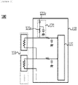
- FIGS. 2 to 4 are diagrams schematically illustrating constituent elements of a system 100 for detecting a temperature of a battery according to an exemplary embodiment of the present invention.
- the system 100 for detecting a temperature of a battery may include temperature detecting units 110 and a battery management system (BMS) 120.
- BMS battery management system
- the system 100 for detecting a temperature of a battery illustrated in FIGS. 2 to 4 is one exemplary embodiment, and constituent elements thereof are not limited to the exemplary embodiment illustrated in FIGS. 2 to 4 , and may be added, changed, or deleted as necessary.
- the temperature detecting units 110 may be connected with one or more batteries, respectively, and may detect temperatures of the connected batteries.
- the temperature detecting units 110 may include one or more thermistors, respectively.
- the thermistor is a semiconductor device, in which various oxides, such as manganese, nickel, copper, cobalt, chrome, and iron, are combined and mixed and sintered, and may be a device having a characteristic in that an electric resistance value is changed according to a temperature.
- the thermistor may include a positive temperature coefficient (PTC) thermistor, in which a temperature and a resistance have a proportion characteristic, a negative temperature coefficient (NTC) thermistor, in which a temperature and a resistance value have an inverse proportion characteristic, and a critical temperature resistor (CIR), in which a resistance value is sharply changed at a specific temperature.
- PTC positive temperature coefficient
- NTC negative temperature coefficient
- CIR critical temperature resistor
- the temperature detecting unit 110 may include a PTC or an NTC, and the BMS 120, which is to be described below, may select a temperature value matched to a resistance value of the PTC or the NTC to enable the temperature detecting unit 110 to detect a temperature of a battery.
- the one or more temperature detecting units 110 may be packaged with a battery module or a battery pack including a target battery, of which a temperature is desired to be measured.
- the BMS 120 may calculate a resistance value of the one or more temperature detecting units 110 by applying a temperature detection voltage to the one or more temperature detecting units 110, and detect temperatures of one or more batteries based on the calculated resistance value.
- the BMS may include a temperature measuring circuit 121 and a control unit 122.
- the temperature measuring circuit 121 may be connected with the one or more temperature detecting units 110 and apply a temperature detection voltage for detecting a temperature to each of the temperature detecting unit 110, and provide the applied voltage value to the control unit 122, which is to be described below.
- the temperature measuring circuit 121 may include a reference resistor 121a and a temperature detecting voltage source 121b.
- the reference resistor 121a may be connected with the temperature detecting unit 110 located at the foremost end among the one or more temperature detecting units 110, and the one or more temperature detecting units 110 may be sequentially connected from the temperature detecting unit 110 located at the foremost end to the temperature detecting unit 110 located at the rearmost end.
- the reference resistor 121a and the one or more temperature detecting units 110 may be connected by a daisy chain connection scheme.
- a switching device 123 may be provided between the reference resistor 121a and each of the one or more temperature detecting units 110, and the reference resistor 121a and the one or more temperature detecting units 110 may be connected with each other or short-circuited through the on/off control of the switching device 123.
- FIG. 4 it is illustrated that the switching device 123 is interposed only between the reference resistor 121a and the one or more temperature detecting units 110, but the present invention is not limited thereto, and the switching device 123 may be interposed between the reference resistor 121a and the temperature detecting unit 110 located at the foremost end, as well as between the reference resistor 121a and the one or more temperature detecting units 110.
- the reference resistor 121a may be a pull-up resistor connected between an input/output terminal of the temperature measuring circuit 121 for measuring a temperature and a temperature detection voltage source 121b, and may be connected with the one or more temperature detecting units 110 and distribute the temperature detection voltage applied from the temperature detection voltage source 121b, which is to be described below.
- the temperature detection voltage source 121b may be connected with the reference resistor 121a, and may output the temperature detection voltage and apply the temperature detection voltage to the one or more temperature detecting units 110.
- the temperature detection voltage may mean a voltage applied to the one or more temperature detecting units 110 for calculating resistance values of the one or more temperature detecting units 110, separately from the voltage output from the battery.
- the temperature measuring circuit 121 may provide a voltage value of the temperature detection voltage, which is output from the temperature detection voltage source 121b and is applied to each of the one or more temperature detecting units 110 to the control unit 122, which is to be described below.
- the temperature measuring circuit 121 may include an analog digital converter (ADV) (not illustrated).
- ADV analog digital converter
- the temperature measuring circuit 121 may convert the temperature detection voltage applied to the one or more temperature detecting units 110 through the ADC into a digital value and provide the digital value to the control unit 122, which is to be described below.
- the control unit 122 may calculate resistance values of the one or more temperature detecting units 110 based on the voltage value of the temperature detection voltage applied to each of the one or more temperature detecting units 110 provided from the temperature measuring circuit 121, and detect temperatures of the one or more batteries connected with the one or more temperature detecting units 110, respectively, based on the calculated resistance value.
- the control unit 122 may calculate a voltage value of a temperature detection voltage, which is to be applied to the one or more connected temperature detecting units 110, based on Equation 1 below.
- V n is a voltage value of the temperature detection voltage, which is to be applied to the n th temperature detecting unit 110
- m is the number of one or more connected temperature detecting units 110
- R p is a resistance value of the reference resistor 121a
- R T is a sum of resistance values of the one or more connected temperature detecting units 110
- ⁇ a n m
- Ra is a sum of resistance values from the n th temperature detecting unit 110 to the m th temperature detecting unit 110
- V p is a voltage value of the temperature detection voltage.
- control unit 122 may measure a voltage V n ' of the temperature detection voltage applied to each of the one or more temperature detecting units 110, and calculate a resistance value R n of each of the one or more temperature detecting units 110 based on the measured voltage value V n ' of the temperature detection voltage and the voltage value V n of the temperature detection voltage calculated through Equation 1.
- the measurement of the voltage value V n ' of the temperature detection voltage by the control unit 122 may mean the reception of the voltage V n ' of the temperature detection voltage applied to each of the one or more temperature detecting units 110 from the temperature measuring circuit 121.
- a temperature detection voltage VP output from the temperature detection voltage source 121b may be applied to the reference resistor 121a and the two temperature detecting units 110-1 and 110-2.
- the temperature measuring circuit 121 may provide voltage values V1' and V2' of the temperature detection voltages actually applied to the two temperature detecting units 110-1 and 110-2 to the control unit 122.
- the voltage values V1' and V2' of the temperature detection voltages actually applied to the two temperature detecting units 110-1 and 110-2 may be 3 V and 1 V, respectively.
- control unit 122 may calculate voltage values V1 and V2 of the temperature detection voltages, which are to be applied to the two temperature detecting units 110-1 and 110-2, by using Equation 1.
- a resistance value R p of the reference resistor 121a is 10 K ⁇ and the voltage value V p of the temperature detection voltage output from the temperature detection voltage source 121b is 5 V
- the voltage value V1 of the temperature detection voltage, which is to be applied to the temperature detecting unit 110-1 located at the foremost end may be 5(R1 + R2)/(10 K ⁇ + R1 + R2)
- the voltage value V2 of the temperature detection voltage, which is to be applied to the second temperature detecting unit 110-2 may be 5 ⁇ R2/(10 K ⁇ + R1 + R2) .
- the control unit 122 may detect a temperature of the battery connected with the temperature detecting unit 110 based on the calculated resistance value R n of the temperature detecting unit 110.
- the BMS 120 may experimentally measure a resistance value according to a temperature of the PTC, and match the measured resistance value to a temperature value and store the matched value in a data table or a look-up table. Then, the control unit 122 may calculate the resistance value of the temperature detecting unit 110 including the PTC, and detect a temperature value of the battery connected with the temperature detecting unit 110 by selecting the temperature value matched with the calculated resistance value in the pre-stored data table or the look-up table.
- the present invention is not limited thereto, and any scheme of calculating a temperature by using a resistance value may be applied.
- a temperature may be detected by substituting the resistance value to the temperature calculation equation considering the component of the thermistor.
- the one or more temperature detecting units 110 and the reference resistor 121a may be in a non-connected state.
- the control unit 122 may sequentially connect the reference resistor 121a and the one or more temperature detecting units 110 and calculate a resistance value of each of the one or more connected temperature detecting units 110 based on Equation 2 below.
- R n is a resistance value of the n th temperature detecting unit 110
- V p is a voltage value of the temperature detection voltage
- V n ' is a voltage value of the temperature detection voltage measured by the n th temperature detecting unit 110
- R p is a resistance value of the reference resistor 121a
- control unit 122 may connect the reference resistor 121a and the temperature detecting unit 110 located at the foremost end.
- the battery temperature detection request may mean a signal output when a user of the system 100 for detecting a temperature of a battery according to the exemplary embodiment of the present invention desires to detect a temperature of the battery or an external system desires to obtain temperature information as state information of the battery.
- the control unit 122 may connect the reference resistor 121a and the temperature detecting unit 110 located at the foremost end by controlling the switching device (not illustrated) interposed between the reference resistor 121a and the temperature detecting unit 110 located at the foremost end, and calculate a resistance value R1 of the temperature detecting unit 110 located at the foremost end by using Equation 2.
- the resistance value R1 of the temperature detecting unit 110 located at the foremost end may be (2.5 V ⁇ 10 K ⁇ )/(5 V - 2.5 V), which is 10 K ⁇ .
- the control unit 122 may connect the second temperature detecting unit 110 and the temperature detecting unit 110 located at the foremost end by controlling the switching device 123 interposed between the second temperature detecting unit 110 and the temperature detecting unit 110 located at the foremost end, and calculate a resistance value R2 of the second temperature detecting unit 110 by using Equation 2.
- the calculated resistance value R2 of the second temperature detecting unit 110 may be (1 V ⁇ (10 K ⁇ + 10 K ⁇ ))/(5 V - 1 V), which is 5 K ⁇ .
- the control unit 122 may calculate up to a resistance value of the temperature detecting unit 110 located at the rearmost end by the foregoing method, and after the resistance value of the temperature detecting unit 110 located at the rearmost end is calculated, the connection state of the reference resistor 121a and the one or more temperature detecting units 110 may be changed to an off state.
- a system 100' for detecting a temperature of a battery according to another exemplary embodiment of the present invention will be described with reference to FIG. 5 .
- FIG. 5 is a diagram schematically illustrating constituent elements of a system 100' for detecting a temperature of a battery according to another exemplary embodiment of the present invention.
- the system 100' for detecting a temperature of a battery according to another exemplary embodiment of the present invention may additionally include a connecting unit 130, compared to the system 100 for detecting a temperature of a battery according to the exemplary embodiment of the present invention illustrated in FIGS. 2 to 4 .
- the connecting unit 130 may perform multiplexing for one or more temperature detecting units 110, and may select any one temperature detecting unit 110 among the one or more temperature detecting units 110 and connect the selected temperature detecting unit 110 with a reference resistor 121a.
- the connecting unit 130 may be a multiplexer, which is capable of performing multiplexing.
- the multiplexing may mean that multiple signals or information stream are simultaneously transmitted in the form of a single complex signal, and a reception side restores the single complex signal to separate signals.
- An input terminal of the connecting unit 130 may be connected with the one or more temperature detecting units 110, and the connecting unit 130 may select any one or more temperature detecting units 110 among the one or more temperature detecting units 110 and selectively connect the selected temperature detecting unit 110 based on the control of a control unit 122.
- a BMS 120 connects the one or more temperature detecting units 110 selected by the connecting unit 130 with the reference resistor 121a and a temperature detection voltage source 121b, and the BMS 120 may disconnect the connection between the one or more temperature detecting units 110, which are not selected by the connecting unit 130 and the temperature detection voltage source 121b. Further, when the connecting unit 130 does not select any temperature detecting unit, the BMS 120 may block the space between the reference resistor 121a and the temperature detection voltage source 121b. To this end, the BMS 120 may further include a switch unit 121c, which is interposed between the reference resistor 121a and the temperature detection voltage source 121b and is capable of controlling the supply of the temperature detection voltage by the temperature detection voltage source 121b.
- the control unit 122 may connect the one or more temperature detecting units 110 connected with a battery, of which a temperature is desired to be detected, and the reference resistor 121a by controlling the connecting unit 130, and apply a temperature detection voltage to the connected temperature detecting unit 110.
- a resistance value R n of the connected temperature detecting unit 110 may be calculated by using a voltage value V P of the temperature detection voltage, a resistance value R P of the reference resistor 121a, and a voltage distribution law.
- a resistance value R P of the reference resistor 121a is 10 K ⁇
- a voltage value V P of the temperature detection voltage is 5 V
- a voltage value V n ' of the temperature detection voltage applied to the temperature detecting unit 110 connected through the connecting unit 130 is 2.5 V
- a resistance value Rn of the connected temperature detecting unit 110 may be calculated as 10 K ⁇ through the voltage distribution law.
- FIG. 6 is a flowchart for describing a series of processes for detecting a temperature of a battery by using the system 100 for detecting a temperature of a battery according to the exemplary embodiment of the present invention.
- a reference resistor and one or more temperature detecting units are connected (S110), and a temperature detection voltage is applied to the connected reference resistor and one or more temperature detecting units (S120). Then, a voltage value of the temperature detection voltage applied to the one or more temperature detecting units in operation S120 is measured (S130), and a voltage value of a temperature detection voltage, which is to be applied to the one or more temperature detecting units, is calculated by using Equation 1 (S140).
- a resistance value of the one or more temperature detecting units is calculated based on the voltage value of the temperature detection voltage applied to the one or more temperature detecting units measured in operation S130 and the voltage value of the temperature detection voltage, which is to be applied to the one or more temperature detecting units, calculated in operation S140 (S150), and a temperature of a battery connected with the one or more temperature detecting units is detected by selecting a temperature value matched with the calculated resistance value (S160).
Landscapes
- Engineering & Computer Science (AREA)
- Manufacturing & Machinery (AREA)
- Chemical & Material Sciences (AREA)
- Chemical Kinetics & Catalysis (AREA)
- Electrochemistry (AREA)
- General Chemical & Material Sciences (AREA)
- Physics & Mathematics (AREA)
- Microelectronics & Electronic Packaging (AREA)
- Nonlinear Science (AREA)
- General Physics & Mathematics (AREA)
- Secondary Cells (AREA)
- Measuring Temperature Or Quantity Of Heat (AREA)
Abstract
Description
- This application claims priority to and the benefit of Korean Patent Application No.
10-2017-0133982 - The present invention relates to a system and a method of detecting a temperature of a battery, and more particularly, to a system and a method of detecting a temperature of a battery, which calculate a resistance value of a temperature detecting unit based on a size of a voltage applied to the temperature detecting unit connected with a battery for measuring a temperature of the battery, and detect the temperature of the battery connected with the temperature detecting unit based on the calculated resistance value.
- In general, in a secondary battery, a plurality of unit secondary battery cell may be united and be used as one battery module, and a plurality of battery modules may be united and used depending on the case in an environment requiring high capacity, such as electric vehicle, an energy storage system, and a non-interrupting electric source supply device.
- When the plurality of battery modules is used together, the battery module is overheated due to an abnormal operation, such as an over current and an over voltage, and thus a problem in that the battery module may explode and become damaged and the like may occur. When the plurality of battery modules is united and used for solving the problem, it is necessary to prevent abnormality from being generated in the battery module by always measuring and detecting a voltage, a current, and a temperature of each individual module.
- As illustrated in
FIG. 1 , in a system for detecting a temperature of a battery in the related art, in order to solve the problem, atemperature detecting sensor 10, which detects a temperature of a battery module, and atemperature measuring circuit 20, which measures a temperature value by using information sensed by thetemperature detecting sensor 10, are installed in each of the plurality of battery modules to measure a temperature of each of the battery modules. However, in the system for detecting a temperature of a battery in the related art, it is necessary to install thetemperature measuring circuit 20 in every battery module, so that there is a problem in that a volume of a component is increased to degrade efficiency, and cost is increased. - In this respect, in order to solve the problem of the system for detecting a temperature of a battery in the related art, the present inventors developed a system and a method of detecting a temperature of a battery, in which a plurality of temperature detecting sensors detects a temperature of a battery module by commonly using one reference resistor, so that it is not necessary to provide a temperature measuring circuit to each temperature detecting sensor connected to a battery module.
- The present invention is conceived to solve the foregoing problems, and the present invention provides a system and a method of detecting a temperature of a battery, which, in order to measure a temperature of one or more batteries, apply one or more temperature detection voltages by connecting one or more temperature detecting units, which are connected to one or more batteries, respectively, and a reference resistor, and calculate a resistance value of each of the one or more temperature detecting units based on a voltage value of the applied temperature detection voltage, and detect temperatures of the one or more batteries connected to the one or more temperature detecting units based on the calculated resistance value.
- An exemplary embodiment of the present invention provides a system for detecting a temperature of a battery, the system including: one or more temperature detecting units, which are connected with one or more batteries, respectively; and a battery management system (BMS), which connects the one or more temperature detecting units with a reference resistor and applies a temperature detection voltage to the one or more temperature detecting units, calculates resistance values of the one or more temperature detecting units based on a voltage value of the applied temperature detection voltage, and detects a temperature of the one or more batteries connected with the one or more temperature detecting units, respectively, based on the calculated resistance value.
- In the exemplary embodiment, the system may further include a connecting unit, which performs multiplexing on the one or more temperature detecting units, and selects any one or more temperature detecting units among the one or more temperature detecting units and connects the selected one or more temperature detecting units with the reference resistor, in which the BMS may include a switch unit, which is interposed between the reference resistor and a temperature detection voltage source and controls the supply of the temperature detection voltage by the temperature detection voltage source.
- In the exemplary embodiment, the BMS may connect the one or more temperature detecting units selected by the connecting unit with the reference resistor and the temperature detection voltage source, and the BMS may disconnect one or more temperature detecting units, which are not selected by the connecting unit, from the temperature detection voltage source, and when the connecting unit does not select any temperature detecting unit, the BMS may block a space between the reference resistor and the temperature detection voltage source by controlling the switch unit.
- In the exemplary embodiment, the one or more temperature detecting units may include one or more thermistors, respectively.
- In the exemplary embodiment, the reference resistor may be connected with a temperature detecting unit located at the foremost end among the one or more temperature detecting units, and the one or more temperature detecting units may be sequentially connected from the temperature detecting unit located at the foremost end to a temperature detecting unit located at the rearmost end.
- In the exemplary embodiment, when the reference resistor and the one or more temperature detecting units are connected, the BMS may calculate a voltage value of the temperature detection voltage, which is to be applied to the one or more connected
temperature detecting units 110, based on Equation 1 below.
- Herein, Vn is a voltage value of the temperature detection voltage, which is to be applied to the nth temperature detecting unit, m is the number of one or more connected temperature detecting units, Rp is a resistance value of the reference resistor, RT is a sum of resistance values of the one or more connected temperature detecting units,

- In the exemplary embodiment, the BMS may measure a voltage value of the temperature detection voltage applied to each of the one or more temperature detecting units, and calculate a resistance value of the one or more temperature detecting units based on the measured voltage value of the temperature detection voltage and the calculated voltage value of the temperature detection voltage.
- In the exemplary embodiment, when the BMS receives a battery temperature detection request in the state where the reference resistor is not connected with the one or more temperature detecting units, the BMS may sequentially connect the reference resistor with the one or more temperature detecting units and calculate a resistance value of each of the one or more connected temperature detecting units based on Equation 2 below.

- Herein, Rn is a resistance value of the nth temperature detecting unit, Vp is a voltage value of the temperature detection voltage, Vn' is a voltage value of the temperature detection voltage measured by the nth temperature detecting unit, Rp is a resistance value of the reference resistor, and


- Another exemplary embodiment of the present invention provides a method of detecting a temperature of a battery, the method including: connecting one or more temperature detecting units, which are connected with one or more batteries, respectively, with a reference resistor and applying a temperature detection voltage to the one or more temperature detecting units; calculating a resistance value of the one or more temperature detecting units based on a voltage value of the temperature detection voltage applied to the one or more temperature detecting units; and detecting a temperature of the one or more batteries, which are connected with the one or more temperature detecting units, respectively, based on the calculated resistance value.
- In the exemplary embodiment, the method may further include performing multiplexing on the one or more temperature detecting units, and selecting one or more temperature detecting units among the one or more temperature detecting units and connecting the selected one or more temperature detecting units with the reference resistor, in which the applying may include controlling the supply of the temperature detection voltage by the temperature detection voltage source by controlling a switch unit, which is interposed between the reference resistor and the temperature detection voltage source.
- In the exemplary embodiment, the applying may further include connecting the one or more selected temperature detecting units with the reference resistor and the temperature detection voltage source, and disconnecting one or more non-selected temperature detecting units from the temperature detection voltage source, and when any temperature detecting unit is not selected, blocking a space between the reference resistor and the temperature detection voltage source by controlling the switch unit.
- In the exemplary embodiment, the one or more temperature detecting units may include one or more thermistors, respectively.
- In the exemplary embodiment, the reference resistor may be connected with a temperature detecting unit located at the foremost end among the one or more temperature detecting units, and the one or more temperature detecting units may be sequentially connected from the temperature detecting unit located at the foremost end to a temperature detecting unit located at the rearmost end.
- In the exemplary embodiment, the calculating may include, when the reference resistor and the one or more temperature detecting units are connected, calculating a voltage value of the temperature detection voltage, which is to be applied to the one or more connected temperature detecting units, based on Equation 1 below.

- Herein, Vn is a voltage value of the temperature detection voltage, which is to be applied to the nth temperature detecting unit, m is the number of one or more connected temperature detecting units, Rp is a resistance value of the reference resistor, RT is a sum of resistance values of the one or more connected temperature detecting units,

- In the exemplary embodiment, the calculating may further include measuring a voltage value of the temperature detection voltage applied to each of the one or more temperature detecting units, and calculating a resistance value of the one or more temperature detecting units based on the measured voltage value of the temperature detection voltage and the calculated voltage value of the temperature detection voltage.
- In the exemplary embodiment, the calculating may include, when the BMS receives a battery temperature detection request in the state where the reference resistor is not connected with the one or more temperature detecting units, sequentially connecting the reference resistor with the one or more temperature detecting units and calculating a resistance value of each of the one or more connected temperature detecting units based on Equation 2 below.

- Herein, Rn is a resistance value of the nth temperature detecting unit, Vp is a voltage value of the temperature detection voltage, Vn' is a voltage value of the temperature detection voltage measured by the nth temperature detecting unit, Rp is a resistance value of the reference resistor, and


- The present invention has an advantage in that it is possible to measure a temperature of a battery by sequentially connecting temperature detecting units, which are connected the batteries, respectively, with a reference resistor, and applying a temperature detection voltage, calculating a resistance value of each of the temperature detecting units based on a size of the applied temperature detection voltage, and detecting temperatures of the batteries connected with the one or more temperature detecting units, respectively, based on the calculated resistance values.
- Further, the present invention has an advantage in that the temperature detecting units connected to the batteries, respectively, share and use one reference resistor, so that it is not necessary to provide a temperature measuring circuit to each of the temperature detecting units, thereby decreasing the use of a pull-up resistor and a capacitor used in the temperature measuring circuit, decreasing a volume of the system, and decreasing cost.
-
-
FIG. 1 is a diagram schematically illustrating a system for detecting a temperature of a battery in the related art. -
FIGS. 2 to 4 are diagrams schematically illustrating constituent elements of asystem 100 for detecting a temperature of a battery according to an exemplary embodiment of the present invention. -
FIG. 5 is a diagram schematically illustrating constituent elements of a system 100' for detecting a temperature of a battery according to another exemplary embodiment of the present invention. -
FIG. 6 is a flowchart for describing a series of processes for detecting a temperature of a battery by using thesystem 100 for detecting a temperature of a battery according to the exemplary embodiment of the present invention. - Hereinafter, an exemplary embodiment is presented for helping understanding of the present invention. However, the exemplary embodiment below is simply provided for easier understanding of the present invention, and contents of the present invention are not limited by the exemplary embodiment.
-
FIGS. 2 to 4 are diagrams schematically illustrating constituent elements of asystem 100 for detecting a temperature of a battery according to an exemplary embodiment of the present invention. - Referring to
FIGS. 2 to 4 , thesystem 100 for detecting a temperature of a battery according to the exemplary embodiment of the present invention may includetemperature detecting units 110 and a battery management system (BMS) 120. - The
system 100 for detecting a temperature of a battery illustrated inFIGS. 2 to 4 is one exemplary embodiment, and constituent elements thereof are not limited to the exemplary embodiment illustrated inFIGS. 2 to 4 , and may be added, changed, or deleted as necessary. - First, the
temperature detecting units 110 may be connected with one or more batteries, respectively, and may detect temperatures of the connected batteries. For example, thetemperature detecting units 110 may include one or more thermistors, respectively. - The thermistor is a semiconductor device, in which various oxides, such as manganese, nickel, copper, cobalt, chrome, and iron, are combined and mixed and sintered, and may be a device having a characteristic in that an electric resistance value is changed according to a temperature. For example, the thermistor may include a positive temperature coefficient (PTC) thermistor, in which a temperature and a resistance have a proportion characteristic, a negative temperature coefficient (NTC) thermistor, in which a temperature and a resistance value have an inverse proportion characteristic, and a critical temperature resistor (CIR), in which a resistance value is sharply changed at a specific temperature.
- In the exemplary embodiment, the
temperature detecting unit 110 may include a PTC or an NTC, and theBMS 120, which is to be described below, may select a temperature value matched to a resistance value of the PTC or the NTC to enable thetemperature detecting unit 110 to detect a temperature of a battery. - In the exemplary embodiment, the one or more
temperature detecting units 110 may be packaged with a battery module or a battery pack including a target battery, of which a temperature is desired to be measured. - The
BMS 120 may calculate a resistance value of the one or moretemperature detecting units 110 by applying a temperature detection voltage to the one or moretemperature detecting units 110, and detect temperatures of one or more batteries based on the calculated resistance value. To this end, the BMS may include atemperature measuring circuit 121 and acontrol unit 122. - The
temperature measuring circuit 121 may be connected with the one or moretemperature detecting units 110 and apply a temperature detection voltage for detecting a temperature to each of thetemperature detecting unit 110, and provide the applied voltage value to thecontrol unit 122, which is to be described below. To this end, thetemperature measuring circuit 121 may include areference resistor 121a and a temperature detectingvoltage source 121b. - The
reference resistor 121a may be connected with thetemperature detecting unit 110 located at the foremost end among the one or moretemperature detecting units 110, and the one or moretemperature detecting units 110 may be sequentially connected from thetemperature detecting unit 110 located at the foremost end to thetemperature detecting unit 110 located at the rearmost end. - In the exemplary embodiment, the
reference resistor 121a and the one or moretemperature detecting units 110 may be connected by a daisy chain connection scheme. - In the exemplary embodiment, a
switching device 123 may be provided between thereference resistor 121a and each of the one or moretemperature detecting units 110, and thereference resistor 121a and the one or moretemperature detecting units 110 may be connected with each other or short-circuited through the on/off control of theswitching device 123. InFIG. 4 , it is illustrated that theswitching device 123 is interposed only between thereference resistor 121a and the one or moretemperature detecting units 110, but the present invention is not limited thereto, and theswitching device 123 may be interposed between thereference resistor 121a and thetemperature detecting unit 110 located at the foremost end, as well as between thereference resistor 121a and the one or moretemperature detecting units 110. - In the exemplary embodiment, the
reference resistor 121a may be a pull-up resistor connected between an input/output terminal of thetemperature measuring circuit 121 for measuring a temperature and a temperaturedetection voltage source 121b, and may be connected with the one or moretemperature detecting units 110 and distribute the temperature detection voltage applied from the temperaturedetection voltage source 121b, which is to be described below. - The temperature
detection voltage source 121b may be connected with thereference resistor 121a, and may output the temperature detection voltage and apply the temperature detection voltage to the one or moretemperature detecting units 110. - Herein, the temperature detection voltage may mean a voltage applied to the one or more
temperature detecting units 110 for calculating resistance values of the one or moretemperature detecting units 110, separately from the voltage output from the battery. - The
temperature measuring circuit 121 may provide a voltage value of the temperature detection voltage, which is output from the temperaturedetection voltage source 121b and is applied to each of the one or moretemperature detecting units 110 to thecontrol unit 122, which is to be described below. For example, thetemperature measuring circuit 121 may include an analog digital converter (ADV) (not illustrated). Thetemperature measuring circuit 121 may convert the temperature detection voltage applied to the one or moretemperature detecting units 110 through the ADC into a digital value and provide the digital value to thecontrol unit 122, which is to be described below. - The
control unit 122 may calculate resistance values of the one or moretemperature detecting units 110 based on the voltage value of the temperature detection voltage applied to each of the one or moretemperature detecting units 110 provided from thetemperature measuring circuit 121, and detect temperatures of the one or more batteries connected with the one or moretemperature detecting units 110, respectively, based on the calculated resistance value. - In the exemplary embodiment, when the
reference resistor 121a and the one or moretemperature detecting units 110 are connected, thecontrol unit 122 may calculate a voltage value of a temperature detection voltage, which is to be applied to the one or more connectedtemperature detecting units 110, based on Equation 1 below.
- Herein, Vn is a voltage value of the temperature detection voltage, which is to be applied to the nth
temperature detecting unit 110, m is the number of one or more connectedtemperature detecting units 110, Rp is a resistance value of thereference resistor 121a, RT is a sum of resistance values of the one or more connectedtemperature detecting units 110,
temperature detecting unit 110 to the mthtemperature detecting unit 110, and Vp is a voltage value of the temperature detection voltage. - Further, the
control unit 122 may measure a voltage Vn' of the temperature detection voltage applied to each of the one or moretemperature detecting units 110, and calculate a resistance value Rn of each of the one or moretemperature detecting units 110 based on the measured voltage value Vn' of the temperature detection voltage and the voltage value Vn of the temperature detection voltage calculated through Equation 1. - Herein, the measurement of the voltage value Vn' of the temperature detection voltage by the
control unit 122 may mean the reception of the voltage Vn' of the temperature detection voltage applied to each of the one or moretemperature detecting units 110 from thetemperature measuring circuit 121. - For example, as illustrated in
FIG. 3 , when thereference resistor 121a and the two temperature detecting units 110-1 and 110-2 are sequentially connected, a temperature detection voltage VP output from the temperaturedetection voltage source 121b may be applied to thereference resistor 121a and the two temperature detecting units 110-1 and 110-2. Thetemperature measuring circuit 121 may provide voltage values V1' and V2' of the temperature detection voltages actually applied to the two temperature detecting units 110-1 and 110-2 to thecontrol unit 122. In this case, the voltage values V1' and V2' of the temperature detection voltages actually applied to the two temperature detecting units 110-1 and 110-2 may be 3 V and 1 V, respectively. Further, thecontrol unit 122 may calculate voltage values V1 and V2 of the temperature detection voltages, which are to be applied to the two temperature detecting units 110-1 and 110-2, by using Equation 1. Herein, when a resistance value Rp of thereference resistor 121a is 10 KΩ and the voltage value Vp of the temperature detection voltage output from the temperaturedetection voltage source 121b is 5 V, the voltage value V1 of the temperature detection voltage, which is to be applied to the temperature detecting unit 110-1 located at the foremost end, may be 5(R1 + R2)/(10 KΩ + R1 + R2), and the voltage value V2 of the temperature detection voltage, which is to be applied to the second temperature detecting unit 110-2, may be 5 ∗ R2/(10 KΩ + R1 + R2) . - In this case, the voltage values V1' and V2' of the temperature detection voltages actually applied to the two temperature detecting units 110-1 and 110-2 and the voltage values V1 and V2 of the temperature detection voltages, which are to be applied to the two temperature detecting units 110-1 and 110-2, need to have the same values, so that two equations, "3 V = (R1 + R2)/(10 KΩ + R1 + R2)" and "1 V = 5 × R2/(10 KΩ + R1 + R2)" may be calculated.
- The
control unit 122 may simultaneously calculate the two calculated equations. For example, thecontrol unit 122 may calculate "R1 = 15 - R - 2" through the first equation, "3 V = (R1 + R2)/(10 KΩ + R1 + R2)", and may calculate values of R1 and R2 as 10 KΩ and 5 KΩ by substituting "R1 = 15 - R - 2" to the second equation. - In the exemplary embodiment, the
control unit 122 may detect a temperature of the battery connected with thetemperature detecting unit 110 based on the calculated resistance value Rn of thetemperature detecting unit 110. For example, when thetemperature detecting unit 110 includes the PTC, theBMS 120 may experimentally measure a resistance value according to a temperature of the PTC, and match the measured resistance value to a temperature value and store the matched value in a data table or a look-up table. Then, thecontrol unit 122 may calculate the resistance value of thetemperature detecting unit 110 including the PTC, and detect a temperature value of the battery connected with thetemperature detecting unit 110 by selecting the temperature value matched with the calculated resistance value in the pre-stored data table or the look-up table. However, the present invention is not limited thereto, and any scheme of calculating a temperature by using a resistance value may be applied. For example, when one or moretemperature detecting units 110 include thermistors, a temperature may be detected by substituting the resistance value to the temperature calculation equation considering the component of the thermistor. - In the exemplary embodiment, the one or more
temperature detecting units 110 and thereference resistor 121a may be in a non-connected state. In this case, when thecontrol unit 122 receives a battery temperature detection request in the state where thereference resistor 121a and the one or moretemperature detecting units 110 are not connected, thecontrol unit 122 may sequentially connect thereference resistor 121a and the one or moretemperature detecting units 110 and calculate a resistance value of each of the one or more connectedtemperature detecting units 110 based on Equation 2 below.
- Herein, Rn is a resistance value of the nth
temperature detecting unit 110, Vp is a voltage value of the temperature detection voltage, Vn' is a voltage value of the temperature detection voltage measured by the nthtemperature detecting unit 110, Rp is a resistance value of thereference resistor 121a, and
temperature detecting unit 110 located at the foremost end to the n-1th temperature detecting unit 110 (however, when n = 1,
- For example, when the battery temperature detection request is received in the state where the
reference resistor 121a and the one or moretemperature detecting units 110 are not connected, thecontrol unit 122 may connect thereference resistor 121a and thetemperature detecting unit 110 located at the foremost end. - Herein, the battery temperature detection request may mean a signal output when a user of the
system 100 for detecting a temperature of a battery according to the exemplary embodiment of the present invention desires to detect a temperature of the battery or an external system desires to obtain temperature information as state information of the battery. - When the battery temperature detection request is input, the
control unit 122 may connect thereference resistor 121a and thetemperature detecting unit 110 located at the foremost end by controlling the switching device (not illustrated) interposed between thereference resistor 121a and thetemperature detecting unit 110 located at the foremost end, and calculate a resistance value R1 of thetemperature detecting unit 110 located at the foremost end by using Equation 2. For example, when a resistance value RP of thereference resistor 121a is 10 KΩ, a voltage value VP of the temperature detection voltage is 5 V, and the voltage value V1' of the temperature detection voltage applied to thetemperature detecting unit 110 located at the foremost end measured by thetemperature measuring circuit 121 is 2.5 V, the resistance value R1 of thetemperature detecting unit 110 located at the foremost end may be (2.5 V × 10 KΩ)/(5 V - 2.5 V), which is 10 KΩ. - After the resistance value R1 of the
temperature detecting unit 110 located at the foremost end is calculated, thecontrol unit 122 may connect the secondtemperature detecting unit 110 and thetemperature detecting unit 110 located at the foremost end by controlling theswitching device 123 interposed between the secondtemperature detecting unit 110 and thetemperature detecting unit 110 located at the foremost end, and calculate a resistance value R2 of the secondtemperature detecting unit 110 by using Equation 2. For example, when the voltage value V2' of the temperature detection voltage applied to the secondtemperature detecting unit 110 is 1 V, the calculated resistance value R2 of the secondtemperature detecting unit 110 may be (1 V × (10 KΩ + 10 KΩ))/(5 V - 1 V), which is 5 KΩ. Thecontrol unit 122 may calculate up to a resistance value of thetemperature detecting unit 110 located at the rearmost end by the foregoing method, and after the resistance value of thetemperature detecting unit 110 located at the rearmost end is calculated, the connection state of thereference resistor 121a and the one or moretemperature detecting units 110 may be changed to an off state. Hereinafter, a system 100' for detecting a temperature of a battery according to another exemplary embodiment of the present invention will be described with reference toFIG. 5 . -
FIG. 5 is a diagram schematically illustrating constituent elements of a system 100' for detecting a temperature of a battery according to another exemplary embodiment of the present invention. - Referring to
FIG. 5 , the system 100' for detecting a temperature of a battery according to another exemplary embodiment of the present invention may additionally include a connectingunit 130, compared to thesystem 100 for detecting a temperature of a battery according to the exemplary embodiment of the present invention illustrated inFIGS. 2 to 4 . - The connecting
unit 130 may perform multiplexing for one or moretemperature detecting units 110, and may select any onetemperature detecting unit 110 among the one or moretemperature detecting units 110 and connect the selectedtemperature detecting unit 110 with areference resistor 121a. For example, the connectingunit 130 may be a multiplexer, which is capable of performing multiplexing. - Herein, the multiplexing may mean that multiple signals or information stream are simultaneously transmitted in the form of a single complex signal, and a reception side restores the single complex signal to separate signals.
- An input terminal of the connecting
unit 130 may be connected with the one or moretemperature detecting units 110, and the connectingunit 130 may select any one or moretemperature detecting units 110 among the one or moretemperature detecting units 110 and selectively connect the selectedtemperature detecting unit 110 based on the control of acontrol unit 122. - A
BMS 120 connects the one or moretemperature detecting units 110 selected by the connectingunit 130 with thereference resistor 121a and a temperaturedetection voltage source 121b, and theBMS 120 may disconnect the connection between the one or moretemperature detecting units 110, which are not selected by the connectingunit 130 and the temperaturedetection voltage source 121b. Further, when the connectingunit 130 does not select any temperature detecting unit, theBMS 120 may block the space between thereference resistor 121a and the temperaturedetection voltage source 121b. To this end, theBMS 120 may further include aswitch unit 121c, which is interposed between thereference resistor 121a and the temperaturedetection voltage source 121b and is capable of controlling the supply of the temperature detection voltage by the temperaturedetection voltage source 121b. - In the system 100' for detecting a temperature of a battery according to another exemplary embodiment of the present invention, when a battery temperature detection request is input from the outside, the
control unit 122 may connect the one or moretemperature detecting units 110 connected with a battery, of which a temperature is desired to be detected, and thereference resistor 121a by controlling the connectingunit 130, and apply a temperature detection voltage to the connectedtemperature detecting unit 110. In this case, a resistance value Rn of the connectedtemperature detecting unit 110 may be calculated by using a voltage value VP of the temperature detection voltage, a resistance value RP of thereference resistor 121a, and a voltage distribution law. For example, when a resistance value RP of thereference resistor 121a is 10 KΩ, a voltage value VP of the temperature detection voltage is 5 V, and a voltage value Vn' of the temperature detection voltage applied to thetemperature detecting unit 110 connected through the connectingunit 130 is 2.5 V, a resistance value Rn of the connectedtemperature detecting unit 110 may be calculated as 10 KΩ through the voltage distribution law. Hereinafter, a method of detecting a temperature of a battery by using thesystem 100 for detecting a temperature of a battery according to the exemplary embodiment of the present invention will be described with reference toFIG. 6 . -
FIG. 6 is a flowchart for describing a series of processes for detecting a temperature of a battery by using thesystem 100 for detecting a temperature of a battery according to the exemplary embodiment of the present invention. - Referring to
FIG. 6 , first, a reference resistor and one or more temperature detecting units are connected (S110), and a temperature detection voltage is applied to the connected reference resistor and one or more temperature detecting units (S120). Then, a voltage value of the temperature detection voltage applied to the one or more temperature detecting units in operation S120 is measured (S130), and a voltage value of a temperature detection voltage, which is to be applied to the one or more temperature detecting units, is calculated by using Equation 1 (S140). - A resistance value of the one or more temperature detecting units is calculated based on the voltage value of the temperature detection voltage applied to the one or more temperature detecting units measured in operation S130 and the voltage value of the temperature detection voltage, which is to be applied to the one or more temperature detecting units, calculated in operation S140 (S150), and a temperature of a battery connected with the one or more temperature detecting units is detected by selecting a temperature value matched with the calculated resistance value (S160).
- The method of detecting a temperature of a battery has been described with reference to the flowchart presented in the drawing. For the simple description, the method is illustrated and described with the series of blocks, but the present invention is not limited to the order of the blocks, and some blocks may occur in a different order from the order illustrated and described in the present specification or may occur with other blocks at the same time, and various other branches, a flow path, and orders of the blocks achieving the same or similar result may be implemented. Further, for the implementation of the method described in the present specification, all of the illustrated blocks may not be required.
- In the forgoing, the present invention has been described with reference to the exemplary embodiment of the present invention, but those skilled in the art may appreciate that the present invention may be variously corrected and changed within the range without departing from the spirit and the area of the present invention described in the appending claims.
Claims (14)
- A system for detecting a temperature of a battery, the system comprising:one or more temperature detecting units, which are connected with one or more batteries, respectively;the one or more temperature detecting units include one or more thermistors, respectively; anda battery management system (BMS), which connects the one or more temperature detecting units with a reference resistor and applies a temperature detection voltage to the one or more temperature detecting units, calculates resistance values of the one or more temperature detecting units based on a voltage value of the applied temperature detection voltage, and detects a temperature of the one or more batteries connected with the one or more temperature detecting units, respectively, based on the calculated resistance value.
- The system of claim 1, further comprising:a connecting unit, which performs multiplexing on the one or more temperature detecting units, and selects any one or more temperature detecting units among the one or more temperature detecting units and connects the selected one or more temperature detecting units with the reference resistor,wherein the BMS includes a switch unit, which is interposed between the reference resistor and a temperature detection voltage source and controls the supply of the temperature detection voltage by the temperature detection voltage source.
- The system of claim 2, wherein the BMS connects the one or more temperature detecting units selected by the connecting unit with the reference resistor and the temperature detection voltage source, and the BMS disconnects one or more temperature detecting units, which are not selected by the connecting unit, from the temperature detection voltage source, and when the connecting unit does not select any temperature detecting unit, the BMS blocks a space between the reference resistor and the temperature detection voltage source by controlling the switch unit.
- The system of claim 1, wherein the reference resistor is connected with a temperature detecting unit located at the foremost end among the one or more temperature detecting units, and
the one or more temperature detecting units are sequentially connected from the temperature detecting unit located at the foremost end to a temperature detecting unit located at the rearmost end. - The system of claim 1, wherein when the reference resistor and the one or more temperature detecting units are connected, the BMS calculates a voltage value of the temperature detection voltage, which is to be applied to the one or more connected temperature detecting units, based on Equation 1 below.


- The system of claim 5, wherein the BMS measures a voltage value of the temperature detection voltage applied to each of the one or more temperature detecting units, and calculates a resistance value of the one or more temperature detecting units based on the measured voltage value of the temperature detection voltage and the calculated voltage value of the temperature detection voltage.
- The system of claim 1, wherein when the BMS receives a battery temperature detection request in the state where the reference resistor is not connected with the one or more temperature detecting units, the BMS sequentially connects the reference resistor with the one or more temperature detecting units and calculates a resistance value of each of the one or more connected temperature detecting units based on Equation 2 below.


- A method of detecting a temperature of a battery, the method comprising:connecting one or more temperature detecting units, which are connected with one or more batteries, respectively, with a reference resistor and applying a temperature detection voltage to the one or more temperature detecting units;the one or more temperature detecting units include one or more thermistors, respectively;calculating a resistance value of the one or more temperature detecting units based on a voltage value of the temperature detection voltage applied to the one or more temperature detecting units; anddetecting a temperature of the one or more batteries, which are connected with the one or more temperature detecting units, respectively, based on the calculated resistance value.
- The method of claim 8, further comprising:performing multiplexing on the one or more temperature detecting units, and selecting one or more temperature detecting units among the one or more temperature detecting units and connecting the selected one or more temperature detecting units with the reference resistor,wherein the applying includes controlling the supply of the temperature detection voltage by the temperature detection voltage source by controlling a switch unit, which is interposed between the reference resistor and the temperature detection voltage source.
- The method of claim 9, wherein the applying further includes connecting the one or more selected temperature detecting units with the reference resistor and the temperature detection voltage source, and disconnecting one or more non-selected temperature detecting units from the temperature detection voltage source, and when any temperature detecting unit is not selected, blocking a space between the reference resistor and the temperature detection voltage source by controlling the switch unit.
- The method of claim 8, wherein the reference resistor is connected with a temperature detecting unit located at the foremost end among the one or more temperature detecting units, and
the one or more temperature detecting units are sequentially connected from the temperature detecting unit located at the foremost end to a temperature detecting unit located at the rearmost end. - The method of claim 8, wherein the calculating includes, when the reference resistor and the one or more temperature detecting units are connected, calculating a voltage value of the temperature detection voltage, which is to be applied to the one or more connected temperature detecting units, based on Equation 1 below.


- The method of claim 12, wherein the calculating further includes measuring a voltage value of the temperature detection voltage applied to each of the one or more temperature detecting units, and calculating a resistance value of the one or more temperature detecting units based on the measured voltage value of the temperature detection voltage and the calculated voltage value of the temperature detection voltage.
- The method of claim 8, wherein the calculating includes, when the BMS receives a battery temperature detection request in the state where the reference resistor is not connected with the one or more temperature detecting units, sequentially connecting the reference resistor with the one or more temperature detecting units and calculating a resistance value of each of the one or more connected temperature detecting units based on Equation 2 below.


Applications Claiming Priority (2)
| Application Number | Priority Date | Filing Date | Title |
|---|---|---|---|
| KR1020170133982A KR102209933B1 (en) | 2017-10-16 | 2017-10-16 | System and method for detecting battery temperature |
| PCT/KR2018/012110 WO2019078559A1 (en) | 2017-10-16 | 2018-10-15 | Battery temperature detection system and method |
Publications (2)
| Publication Number | Publication Date |
|---|---|
| EP3624254A1 true EP3624254A1 (en) | 2020-03-18 |
| EP3624254A4 EP3624254A4 (en) | 2020-07-22 |
Family
ID=66173767
Family Applications (1)
| Application Number | Title | Priority Date | Filing Date |
|---|---|---|---|
| EP18867901.3A Pending EP3624254A4 (en) | 2017-10-16 | 2018-10-15 | SYSTEM AND METHOD FOR DETECTING A BATTERY TEMPERATURE |
Country Status (6)
| Country | Link |
|---|---|
| US (1) | US11940335B2 (en) |
| EP (1) | EP3624254A4 (en) |
| JP (1) | JP7099781B2 (en) |
| KR (1) | KR102209933B1 (en) |
| CN (1) | CN110800152A (en) |
| WO (1) | WO2019078559A1 (en) |
Cited By (1)
| Publication number | Priority date | Publication date | Assignee | Title |
|---|---|---|---|---|
| US12283669B2 (en) | 2019-10-29 | 2025-04-22 | Lg Energy Solution, Ltd. | Temperature measuring apparatus, battery apparatus including the same and temperature measuring method |
Families Citing this family (6)
| Publication number | Priority date | Publication date | Assignee | Title |
|---|---|---|---|---|
| KR102319005B1 (en) * | 2019-11-04 | 2021-10-28 | 세메스 주식회사 | Temperature measuring device and bake chamber |
| KR20230056158A (en) | 2021-10-20 | 2023-04-27 | 주식회사 엘지에너지솔루션 | Thermistor sequence curcuit and temperature detecting apparatus including the same |
| US20230245508A1 (en) * | 2022-02-02 | 2023-08-03 | TE Connectivity Services Gmbh | Sensing Assembly Having a Multiplexer |
| CN220627729U (en) | 2022-06-27 | 2024-03-19 | 米沃奇电动工具公司 | Fuses and devices including conductive paths for the passage of electric current |
| KR102966338B1 (en) * | 2023-11-15 | 2026-05-19 | 주식회사 엘지에너지솔루션 | Method and electronic device of determining temperature of target battery |
| CN120073110B (en) * | 2025-04-28 | 2025-08-29 | 江苏时代新能源科技有限公司 | Battery management system, battery management method, and computer-readable storage medium |
Family Cites Families (22)
| Publication number | Priority date | Publication date | Assignee | Title |
|---|---|---|---|---|
| US5929344A (en) * | 1997-07-28 | 1999-07-27 | Micro Motion, Inc. | Circuitry for reducing the number of conductors for multiple resistive sensors on a coriolis effect mass flowmeter |
| JP3864537B2 (en) * | 1998-02-19 | 2007-01-10 | トヨタ自動車株式会社 | Temperature sensor abnormality detection method and temperature detection apparatus |
| JP3738233B2 (en) * | 2002-04-26 | 2006-01-25 | 三洋電機株式会社 | Power supply for vehicle |
| JP4095878B2 (en) * | 2002-10-28 | 2008-06-04 | 松下電器産業株式会社 | Battery management system, battery pack, and charge state measuring method thereof |
| JP2004157024A (en) | 2002-11-07 | 2004-06-03 | Omron Corp | Temperature detector |
| JP4934419B2 (en) * | 2006-12-14 | 2012-05-16 | パナソニック株式会社 | Battery pack |
| JP5213412B2 (en) | 2007-10-29 | 2013-06-19 | 三洋電機株式会社 | Power supply temperature detection method |
| US8267578B2 (en) * | 2009-02-04 | 2012-09-18 | Schlumberger Technology Corporation | Methods and systems for temperature compensated temperature measurements |
| JP5390925B2 (en) | 2009-04-24 | 2014-01-15 | パナソニック株式会社 | Battery pack |
| JP2011075530A (en) | 2009-10-02 | 2011-04-14 | Hanshin Electric Co Ltd | Thermistor monitoring device |
| JP4965750B2 (en) * | 2010-07-30 | 2012-07-04 | パナソニック株式会社 | Battery system |
| KR101451806B1 (en) * | 2010-09-16 | 2014-10-17 | 삼성에스디아이 주식회사 | Energy storage system |
| US9075090B2 (en) * | 2011-08-11 | 2015-07-07 | Qualcomm Incorporated | Battery monitoring circuit |
| JP2014211307A (en) | 2011-08-30 | 2014-11-13 | 三洋電機株式会社 | Battery system, charge state estimation device, electric vehicle, movable body, electric power storage device and power supply device |
| JP5888499B2 (en) * | 2012-02-01 | 2016-03-22 | 横河電機株式会社 | Temperature transmitter |
| FR2996694B1 (en) | 2012-10-04 | 2015-09-18 | Commissariat Energie Atomique | CIRCUIT FOR MANAGING THE CHARGE OF A BATTERY |
| KR102082866B1 (en) | 2013-04-18 | 2020-04-14 | 삼성에스디아이 주식회사 | Battery management system and driving method thereof |
| KR102072247B1 (en) * | 2013-07-16 | 2020-01-31 | 현대모비스 주식회사 | Temperature management system of battery pack and method thereof |
| KR20150128015A (en) | 2014-05-08 | 2015-11-18 | 암페놀센싱코리아 유한회사 | Contact type sensor for measuring temperature of vehicle battery |
| JP6211493B2 (en) | 2014-09-10 | 2017-10-11 | 矢崎総業株式会社 | Temperature detection device |
| KR101749730B1 (en) | 2014-12-29 | 2017-06-21 | 주식회사 엘지화학 | Apparatus and method for cell balancing |
| KR20170133982A (en) | 2016-05-27 | 2017-12-06 | 정성채 | Apparatus for broadcasting using fm frequency bandwidth of leakage coaxial cable |
-
2017
- 2017-10-16 KR KR1020170133982A patent/KR102209933B1/en active Active
-
2018
- 2018-10-15 US US16/640,135 patent/US11940335B2/en active Active
- 2018-10-15 WO PCT/KR2018/012110 patent/WO2019078559A1/en not_active Ceased
- 2018-10-15 CN CN201880042954.5A patent/CN110800152A/en active Pending
- 2018-10-15 EP EP18867901.3A patent/EP3624254A4/en active Pending
- 2018-10-15 JP JP2019566948A patent/JP7099781B2/en active Active
Cited By (1)
| Publication number | Priority date | Publication date | Assignee | Title |
|---|---|---|---|---|
| US12283669B2 (en) | 2019-10-29 | 2025-04-22 | Lg Energy Solution, Ltd. | Temperature measuring apparatus, battery apparatus including the same and temperature measuring method |
Also Published As
| Publication number | Publication date |
|---|---|
| JP2020523569A (en) | 2020-08-06 |
| US11940335B2 (en) | 2024-03-26 |
| US20210080332A1 (en) | 2021-03-18 |
| JP7099781B2 (en) | 2022-07-12 |
| EP3624254A4 (en) | 2020-07-22 |
| KR102209933B1 (en) | 2021-01-29 |
| KR20190042260A (en) | 2019-04-24 |
| WO2019078559A1 (en) | 2019-04-25 |
| CN110800152A (en) | 2020-02-14 |
Similar Documents
| Publication | Publication Date | Title |
|---|---|---|
| US11940335B2 (en) | Battery temperature detection system and method | |
| JP6805462B2 (en) | Insulation resistance calculation system and method | |
| JP7471337B2 (en) | Monitoring system for series-connected battery cells | |
| JP3323498B2 (en) | Battery monitoring system during charging and discharging | |
| US9291681B2 (en) | Monitoring apparatus and method of battery contact point in charge/discharge system with batteries connected in series | |
| CN104220886B (en) | Apparatus and method for measuring insulation resistance of battery | |
| EP3534168B1 (en) | Battery control device | |
| US9755281B2 (en) | Method for connecting battery cells in a battery, battery, and monitoring device | |
| US20170125856A1 (en) | Storage battery deterioration measurement device and power storage system | |
| US10353013B2 (en) | Voltage detection device, voltage detection method, abnormality determination device, abnormality determination method, and battery pack system | |
| KR102319239B1 (en) | Battery pack | |
| CN106415295A (en) | Switch deterioration detection device and method | |
| EP3859865A1 (en) | Battery module for detecting high temperature of battery cell | |
| JP2013024718A (en) | Temperature abnormality detecting sensor | |
| EP4135097A2 (en) | Battery pack and control method for battery pack | |
| JP2020008480A (en) | Temperature sensor abnormality determination device and temperature sensor abnormality determination method | |
| EP3700050B1 (en) | Method and battery management system for controlling cell balancing | |
| CN112789781B (en) | Battery management system | |
| KR20230063689A (en) | Battery diagnosis method based on resistance degradation and battery system using the same | |
| JP2012220344A (en) | Cell voltage measurement device | |
| US20150260796A1 (en) | Battery cell state-of-charge estimation and readjustment method | |
| EP4447191A1 (en) | Battery pack and method of controlling the battery pack | |
| JP6299378B2 (en) | Battery monitoring device and battery monitoring method | |
| EP4401194B1 (en) | Battery pack and method of controlling the same | |
| JP6880988B2 (en) | Battery monitoring integrated circuit device |
Legal Events
| Date | Code | Title | Description |
|---|---|---|---|
| STAA | Information on the status of an ep patent application or granted ep patent |
Free format text: STATUS: THE INTERNATIONAL PUBLICATION HAS BEEN MADE |
|
| PUAI | Public reference made under article 153(3) epc to a published international application that has entered the european phase |
Free format text: ORIGINAL CODE: 0009012 |
|
| STAA | Information on the status of an ep patent application or granted ep patent |
Free format text: STATUS: REQUEST FOR EXAMINATION WAS MADE |
|
| 17P | Request for examination filed |
Effective date: 20191211 |
|
| AK | Designated contracting states |
Kind code of ref document: A1 Designated state(s): AL AT BE BG CH CY CZ DE DK EE ES FI FR GB GR HR HU IE IS IT LI LT LU LV MC MK MT NL NO PL PT RO RS SE SI SK SM TR |
|
| AX | Request for extension of the european patent |
Extension state: BA ME |
|
| A4 | Supplementary search report drawn up and despatched |
Effective date: 20200619 |
|
| RIC1 | Information provided on ipc code assigned before grant |
Ipc: H01M 10/48 20060101AFI20200615BHEP Ipc: H01M 10/42 20060101ALI20200615BHEP |
|
| DAV | Request for validation of the european patent (deleted) | ||
| DAX | Request for extension of the european patent (deleted) | ||
| RAP1 | Party data changed (applicant data changed or rights of an application transferred) |
Owner name: LG ENERGY SOLUTION LTD. |
|
| RAP3 | Party data changed (applicant data changed or rights of an application transferred) |
Owner name: LG ENERGY SOLUTION, LTD. |
|
| STAA | Information on the status of an ep patent application or granted ep patent |
Free format text: STATUS: EXAMINATION IS IN PROGRESS |
|
| 17Q | First examination report despatched |
Effective date: 20221129 |