EP3624227B1 - Battery module having enhanced electrical connection stability - Google Patents
Battery module having enhanced electrical connection stability Download PDFInfo
- Publication number
- EP3624227B1 EP3624227B1 EP18881818.1A EP18881818A EP3624227B1 EP 3624227 B1 EP3624227 B1 EP 3624227B1 EP 18881818 A EP18881818 A EP 18881818A EP 3624227 B1 EP3624227 B1 EP 3624227B1
- Authority
- EP
- European Patent Office
- Prior art keywords
- electrode lead
- bus bar
- positive electrode
- pouch
- lead group
- Prior art date
- Legal status (The legal status is an assumption and is not a legal conclusion. Google has not performed a legal analysis and makes no representation as to the accuracy of the status listed.)
- Active
Links
- 238000005452 bending Methods 0.000 claims description 23
- 239000004020 conductor Substances 0.000 claims description 3
- 239000010410 layer Substances 0.000 description 23
- 238000000034 method Methods 0.000 description 11
- 229910052782 aluminium Inorganic materials 0.000 description 10
- XAGFODPZIPBFFR-UHFFFAOYSA-N aluminium Chemical compound [Al] XAGFODPZIPBFFR-UHFFFAOYSA-N 0.000 description 10
- RYGMFSIKBFXOCR-UHFFFAOYSA-N Copper Chemical compound [Cu] RYGMFSIKBFXOCR-UHFFFAOYSA-N 0.000 description 5
- 229910052802 copper Inorganic materials 0.000 description 5
- 239000010949 copper Substances 0.000 description 5
- 238000010586 diagram Methods 0.000 description 5
- 229910052751 metal Inorganic materials 0.000 description 5
- 239000002184 metal Substances 0.000 description 5
- 238000009413 insulation Methods 0.000 description 4
- 238000003466 welding Methods 0.000 description 4
- 230000000694 effects Effects 0.000 description 3
- 238000004519 manufacturing process Methods 0.000 description 3
- 239000007769 metal material Substances 0.000 description 3
- 239000002390 adhesive tape Substances 0.000 description 2
- 238000002485 combustion reaction Methods 0.000 description 2
- 239000003792 electrolyte Substances 0.000 description 2
- 230000002452 interceptive effect Effects 0.000 description 2
- 229920005672 polyolefin resin Polymers 0.000 description 2
- 229910052709 silver Inorganic materials 0.000 description 2
- 239000004332 silver Substances 0.000 description 2
- WHXSMMKQMYFTQS-UHFFFAOYSA-N Lithium Chemical compound [Li] WHXSMMKQMYFTQS-UHFFFAOYSA-N 0.000 description 1
- 239000004677 Nylon Substances 0.000 description 1
- 239000004743 Polypropylene Substances 0.000 description 1
- QVGXLLKOCUKJST-UHFFFAOYSA-N atomic oxygen Chemical compound [O] QVGXLLKOCUKJST-UHFFFAOYSA-N 0.000 description 1
- 230000000903 blocking effect Effects 0.000 description 1
- 230000006835 compression Effects 0.000 description 1
- 238000007906 compression Methods 0.000 description 1
- 238000007796 conventional method Methods 0.000 description 1
- 238000013016 damping Methods 0.000 description 1
- 230000001419 dependent effect Effects 0.000 description 1
- 229910052744 lithium Inorganic materials 0.000 description 1
- 238000012986 modification Methods 0.000 description 1
- 230000004048 modification Effects 0.000 description 1
- 239000007773 negative electrode material Substances 0.000 description 1
- 229920001778 nylon Polymers 0.000 description 1
- 229910052760 oxygen Inorganic materials 0.000 description 1
- 239000001301 oxygen Substances 0.000 description 1
- -1 polypropylene Polymers 0.000 description 1
- 229920001155 polypropylene Polymers 0.000 description 1
- 239000007774 positive electrode material Substances 0.000 description 1
- 238000003825 pressing Methods 0.000 description 1
- 239000011241 protective layer Substances 0.000 description 1
- 229920005989 resin Polymers 0.000 description 1
- 239000011347 resin Substances 0.000 description 1
- 238000007789 sealing Methods 0.000 description 1
- 239000003566 sealing material Substances 0.000 description 1
- 239000000758 substrate Substances 0.000 description 1
- 239000013589 supplement Substances 0.000 description 1
Images


Classifications
-
- H—ELECTRICITY
- H01—ELECTRIC ELEMENTS
- H01M—PROCESSES OR MEANS, e.g. BATTERIES, FOR THE DIRECT CONVERSION OF CHEMICAL ENERGY INTO ELECTRICAL ENERGY
- H01M50/00—Constructional details or processes of manufacture of the non-active parts of electrochemical cells other than fuel cells, e.g. hybrid cells
- H01M50/50—Current conducting connections for cells or batteries
- H01M50/502—Interconnectors for connecting terminals of adjacent batteries; Interconnectors for connecting cells outside a battery casing
-
- H—ELECTRICITY
- H01—ELECTRIC ELEMENTS
- H01M—PROCESSES OR MEANS, e.g. BATTERIES, FOR THE DIRECT CONVERSION OF CHEMICAL ENERGY INTO ELECTRICAL ENERGY
- H01M50/00—Constructional details or processes of manufacture of the non-active parts of electrochemical cells other than fuel cells, e.g. hybrid cells
- H01M50/50—Current conducting connections for cells or batteries
- H01M50/543—Terminals
- H01M50/552—Terminals characterised by their shape
- H01M50/553—Terminals adapted for prismatic, pouch or rectangular cells
- H01M50/557—Plate-shaped terminals
-
- H—ELECTRICITY
- H01—ELECTRIC ELEMENTS
- H01M—PROCESSES OR MEANS, e.g. BATTERIES, FOR THE DIRECT CONVERSION OF CHEMICAL ENERGY INTO ELECTRICAL ENERGY
- H01M50/00—Constructional details or processes of manufacture of the non-active parts of electrochemical cells other than fuel cells, e.g. hybrid cells
- H01M50/10—Primary casings, jackets or wrappings of a single cell or a single battery
- H01M50/116—Primary casings, jackets or wrappings of a single cell or a single battery characterised by the material
- H01M50/117—Inorganic material
- H01M50/119—Metals
-
- H—ELECTRICITY
- H01—ELECTRIC ELEMENTS
- H01M—PROCESSES OR MEANS, e.g. BATTERIES, FOR THE DIRECT CONVERSION OF CHEMICAL ENERGY INTO ELECTRICAL ENERGY
- H01M50/00—Constructional details or processes of manufacture of the non-active parts of electrochemical cells other than fuel cells, e.g. hybrid cells
- H01M50/10—Primary casings, jackets or wrappings of a single cell or a single battery
- H01M50/116—Primary casings, jackets or wrappings of a single cell or a single battery characterised by the material
- H01M50/121—Organic material
-
- H—ELECTRICITY
- H01—ELECTRIC ELEMENTS
- H01M—PROCESSES OR MEANS, e.g. BATTERIES, FOR THE DIRECT CONVERSION OF CHEMICAL ENERGY INTO ELECTRICAL ENERGY
- H01M50/00—Constructional details or processes of manufacture of the non-active parts of electrochemical cells other than fuel cells, e.g. hybrid cells
- H01M50/10—Primary casings, jackets or wrappings of a single cell or a single battery
- H01M50/116—Primary casings, jackets or wrappings of a single cell or a single battery characterised by the material
- H01M50/124—Primary casings, jackets or wrappings of a single cell or a single battery characterised by the material having a layered structure
-
- H—ELECTRICITY
- H01—ELECTRIC ELEMENTS
- H01M—PROCESSES OR MEANS, e.g. BATTERIES, FOR THE DIRECT CONVERSION OF CHEMICAL ENERGY INTO ELECTRICAL ENERGY
- H01M50/00—Constructional details or processes of manufacture of the non-active parts of electrochemical cells other than fuel cells, e.g. hybrid cells
- H01M50/10—Primary casings, jackets or wrappings of a single cell or a single battery
- H01M50/172—Arrangements of electric connectors penetrating the casing
- H01M50/174—Arrangements of electric connectors penetrating the casing adapted for the shape of the cells
- H01M50/178—Arrangements of electric connectors penetrating the casing adapted for the shape of the cells for pouch or flexible bag cells
-
- H—ELECTRICITY
- H01—ELECTRIC ELEMENTS
- H01M—PROCESSES OR MEANS, e.g. BATTERIES, FOR THE DIRECT CONVERSION OF CHEMICAL ENERGY INTO ELECTRICAL ENERGY
- H01M50/00—Constructional details or processes of manufacture of the non-active parts of electrochemical cells other than fuel cells, e.g. hybrid cells
- H01M50/20—Mountings; Secondary casings or frames; Racks, modules or packs; Suspension devices; Shock absorbers; Transport or carrying devices; Holders
- H01M50/204—Racks, modules or packs for multiple batteries or multiple cells
- H01M50/207—Racks, modules or packs for multiple batteries or multiple cells characterised by their shape
- H01M50/211—Racks, modules or packs for multiple batteries or multiple cells characterised by their shape adapted for pouch cells
-
- H—ELECTRICITY
- H01—ELECTRIC ELEMENTS
- H01M—PROCESSES OR MEANS, e.g. BATTERIES, FOR THE DIRECT CONVERSION OF CHEMICAL ENERGY INTO ELECTRICAL ENERGY
- H01M50/00—Constructional details or processes of manufacture of the non-active parts of electrochemical cells other than fuel cells, e.g. hybrid cells
- H01M50/50—Current conducting connections for cells or batteries
- H01M50/502—Interconnectors for connecting terminals of adjacent batteries; Interconnectors for connecting cells outside a battery casing
- H01M50/503—Interconnectors for connecting terminals of adjacent batteries; Interconnectors for connecting cells outside a battery casing characterised by the shape of the interconnectors
-
- H—ELECTRICITY
- H01—ELECTRIC ELEMENTS
- H01M—PROCESSES OR MEANS, e.g. BATTERIES, FOR THE DIRECT CONVERSION OF CHEMICAL ENERGY INTO ELECTRICAL ENERGY
- H01M50/00—Constructional details or processes of manufacture of the non-active parts of electrochemical cells other than fuel cells, e.g. hybrid cells
- H01M50/50—Current conducting connections for cells or batteries
- H01M50/531—Electrode connections inside a battery casing
-
- H—ELECTRICITY
- H01—ELECTRIC ELEMENTS
- H01M—PROCESSES OR MEANS, e.g. BATTERIES, FOR THE DIRECT CONVERSION OF CHEMICAL ENERGY INTO ELECTRICAL ENERGY
- H01M50/00—Constructional details or processes of manufacture of the non-active parts of electrochemical cells other than fuel cells, e.g. hybrid cells
- H01M50/50—Current conducting connections for cells or batteries
- H01M50/572—Means for preventing undesired use or discharge
- H01M50/574—Devices or arrangements for the interruption of current
- H01M50/579—Devices or arrangements for the interruption of current in response to shock
-
- H—ELECTRICITY
- H01—ELECTRIC ELEMENTS
- H01M—PROCESSES OR MEANS, e.g. BATTERIES, FOR THE DIRECT CONVERSION OF CHEMICAL ENERGY INTO ELECTRICAL ENERGY
- H01M2220/00—Batteries for particular applications
- H01M2220/20—Batteries in motive systems, e.g. vehicle, ship, plane
-
- Y—GENERAL TAGGING OF NEW TECHNOLOGICAL DEVELOPMENTS; GENERAL TAGGING OF CROSS-SECTIONAL TECHNOLOGIES SPANNING OVER SEVERAL SECTIONS OF THE IPC; TECHNICAL SUBJECTS COVERED BY FORMER USPC CROSS-REFERENCE ART COLLECTIONS [XRACs] AND DIGESTS
- Y02—TECHNOLOGIES OR APPLICATIONS FOR MITIGATION OR ADAPTATION AGAINST CLIMATE CHANGE
- Y02E—REDUCTION OF GREENHOUSE GAS [GHG] EMISSIONS, RELATED TO ENERGY GENERATION, TRANSMISSION OR DISTRIBUTION
- Y02E60/00—Enabling technologies; Technologies with a potential or indirect contribution to GHG emissions mitigation
- Y02E60/10—Energy storage using batteries
Definitions
- the present disclosure relates to a battery module, and more particularly, to a battery module capable of preventing an electric contact between a pouch case and an electrode lead in pouch-type battery cells connected in parallel within the battery module and improving bonding stability between a bus bar and a plurality of electrode leads overlapped in multiple layers at a parallel connection structure.
- lithium secondary batteries may be classified into a can-type secondary battery in which an electrode assembly is included in a metal can and a pouch-type secondary battery in which an electrode assembly is included in a pouch made of an aluminum sheet, depending on the exterior shape.
- the electric vehicles include hybrid electric vehicles, plug-in hybrid electric vehicles, and pure electric vehicles powered by an electric motor and a battery without an internal combustion engine.
- pouch-type secondary batteries are widely used for the mid-to-large-sized devices since they are easily stacked.
- the battery modules of the mid-to-large-sized devices are implemented by stacking the pouch-type secondary batteries and connecting the electrode leads in series and/or in parallel.
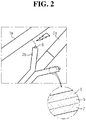
- a positive electrode lead 1a of one pouch-type battery cell 1 frequently interferes with a terrace front end 2b of a pouch case of another pouch-type battery cell 2 adjacent thereto.
- the pouch case has a layered structure in which an outer insulation layer 7, an aluminum layer 6, and an inner adhesion layer 5 are laminated in order.
- the electrode lead is allowed to contact the outer insulation layer 7 of the pouch case, but an electric short may occur when the electrode contacts the terrace front end 2b at which the aluminum layer 6 may be exposed.
- the positive electrode lead 1a contacts the aluminum layer 6 of the pouch case in a state where the insulation of the pouch case is broken, a short circuit may occur, which greatly increase the possibility of ignition.
- the pouch-type secondary battery may be somewhat vulnerable to an external physical impact due to its configuration.
- the vulnerability may become more serious so that a crack or a damage may occur in the inner adhesion layer 5 merely with a minor physical impact, thereby converting the aluminum layer 6 into an electrode.
- the aluminum layer 6 may be polarized since it is in direct contact with the electrode assembly.
- the negative electrode plate is disposed at an outermost side of the electrode assembly, the aluminum layer 6 becomes a negative electrode. In a state where the aluminum layer 6 becomes a negative electrode, when the positive electrode lead 1a contacts the terrace front end 2b of the pouch case as shown in FIG. 2 , a short circuit may occur, which may lead to ignition of the pouch-type secondary battery.
- US 2016/226043 relates to a battery module, wherein electrode leads of the battery cells have a damping structure.
- the present disclosure is directed to providing a battery module, which may prevent an electric contact between an electrode lead and a terrace front end of a pouch case in adjacent pouch-type battery cells among a plurality of pouch-type battery cells connected in parallel and may also improve bonding stability between a plurality of electrode leads and a bus bar overlapped in plural layers in a parallel connection structure.
- a battery module comprising pouch-type battery cells stacked on each other and electrically connected in series and/or in parallel.
- electrode leads of other pouch-type battery cells are biased to allow ends of the electrode leads to be overlapped, and each of the pouch-type battery cells include an R bending portion at which a boundary region between a terrace of a pouch case and the electrode leads is bent toward a direction in which the electrode leads are biased.
- the R bending portion has a rounded recess shape, and the terrace may be bent to allow a front end thereof is disposed near a deepest region of the rounded recess shape of the R bending portion.
- the battery module may comprise a positive electrode lead group in which ends of at least two positive electrode leads are overlapped and linearly extend; and a negative electrode lead group in which ends of at least two negative electrode leads provided in a same number as the positive electrode leads are overlapped and linearly extend in a same direction as the positive electrode lead group.
- a positive electrode lead and a first negative electrode lead that face each other at a shortest distance among the positive electrode lead group and the negative electrode lead group other positive electrode leads may be biased toward the first positive electrode lead, and other negative electrode leads may be biased toward the first negative electrode lead.
- the battery module may comprise a bus bar assembly configured to electrically connect the positive electrode lead group and the negative electrode lead group.
- the bus bar assembly may include a fixed bus bar formed in a rod-shaped conductor; a pair of movable bus bars disposed to be spaced apart from each other at both sides of the fixed bus bar with the fixed bus bar interposed therebetween to form a fitting space between the movable bus bars and the fixed bus bar for the positive electrode lead group and the negative electrode lead group to be respectively inserted therein; and an adhering member configured to move the pair of movable bus bars toward the fixed bus bar with the positive electrode lead group and the negative electrode lead group disposed in the fitting space to allow the positive electrode lead group and the negative electrode lead group to be coupled to the fixed bus bar.
- the adhering member may be a leaf spring having both ends coupled to the pair of movable bus bars to move the pair of movable bus bars in directions facing each other due to an elastic restoring force thereof.
- Each of the pair of movable bus bars may include a contact portion provided in parallel to the fixed bus bar; and gap adjusting portions that extend from both ends of the contact portion and are bent, and the gap adjusting portion may be connected to the adhering member.
- the pair of movable bus bars may be disposed symmetrically with respect to the fixed bus bar to surround the fixed bus bar.
- a battery pack comprising the battery module described above.
- an electric contact between the electrode lead and the terrace front end of the pouch case in adjacent pouch-type battery cells among a plurality of pouch-type battery cells connected in parallel may be prevented, and therefore, safety may be improved.
- the high efficiency is ensured compared to where a separate component or insulating taping is used in order to prevent an electrical short between the electrode lead and the pouch case.
- the automation rate of the battery module production line may be improved.
- a battery module includes a cell stack having pouch-type battery cells 10 stacked in one direction and electrically connected in series and/or in parallel, a voltage sensing assembly for electrically connecting the cell stack and sensing a voltage of the cell stack, a module housing for accommodating the cell stack to be protected from exterior elements and providing a mechanical support to the cell stack, and various devices for controlling charge and discharge of the pouch-type battery cells 10 such as a battery management system (BMS), a current sensor, a fuse, and the like.
- BMS battery management system
- a current sensor a fuse
- any configuration that may blur the gist of the present disclosure will not be explained, and characteristic features of the present disclosure will be described in detail.
- FIG. 3 is a diagram schematically showing a pouch-type battery cell 10 according to an embodiment of the present disclosure.
- a pouch-type battery cell 10 applied to the battery module according to the present disclosure includes an electrode assembly 13, a pouch case, and an electrode lead having one end connected to the electrode assembly 13 and the other end that extends out of the pouch case.
- a part of the electrode lead is thermally bonded together with the pouch case.
- the thermal bonding layer of the pouch case is made of a resin layer and the electrode lead is made of a metal, the thermal bonding between the electrode lead and the pouch case may be insufficient.
- an adhesive tape 16 may be used.
- the electrode lead may be thermally bonded to the pouch case in a state where its periphery is taped with the adhesive tape 16.
- the electrode assembly 13 may include a positive electrode plate, a separator, and a negative electrode plate, and may be configured so that the positive electrode plate and the negative electrode plate respectively coated with a positive electrode active material and a negative electrode active material are repeatedly laminated with the separator interposed therebetween.
- the negative electrode plate is slightly larger in size than the positive electrode plate and thus is disposed at the top and bottom ends of the electrode assembly 13.
- the electrode assembly 13 may be accommodated in the pouch case together with an electrolyte in a sealed state.
- the pouch case has a multi-layered structure in which a polyolefin resin layer that is a thermal bonding layer serving as a sealing material, a substrate for maintaining mechanical strength, an aluminum (AL) layer that is a metal layer for blocking moisture and oxygen, and a nylon layer that serves as a protective layer are laminated.
- Casted polypropylene (CPP) is often used as the polyolefin resin layer that serves as a thermal bonding layer.
- the pouch case is provided so that its edges are sealed after the electrode assembly 13 is accommodated therein and an electrolyte is injected therein.
- the pouch case includes a first pouch sheet 11a and a second pouch sheet 11b.
- the first pouch sheet 11a may be formed to accommodate the electrode assembly 13 in a central region thereof, and the second pouch sheet 11b may be provided to face the first pouch sheet 1 la to allow their edges to be thermally bonded to each other.
- the thermally bonded edge region of the pouch case is defined as a terrace 12.
- each of the pouch-type battery cells 10 of the battery module according to the present disclosure further includes an R bending portion 17.
- the R bending portion 17 is a portion prepared by bending a boundary region between the terrace 12 of the pouch exterior and the electrode lead. When multiple pouch-type battery cells 10 are connected in parallel, the R bending portion 17 prevents the electrode lead and a terrace front end 12a of the pouch exterior from interfering with each other or from contacting each other.
- the terrace front end 12a of the pouch case is disposed at a position where the R bending portion 17 is sharply bent compared to other portions to deviate from a linear line along which the electrode lead extends from the terrace 12 of the pouch exterior.
- the R bending portion 17 may have a rounded or arc recess shape in a region before and after the boundary region between the terrace 12 of the pouch exterior and the electrode lead.
- the terrace front end 12a of the pouch exterior is preferably disposed at a deepest region of the recess shape of the R bending portion 17.
- the R bending portion 17 is formed in a same direction as the direction in which, based on an electrode lead of one pouch-type battery cell 10, electrode leads of other pouch-type battery cells 10 are biased when several pouch-type battery cells 10 are connected in parallel.
- the pouch-type battery cells 10 of the battery module according to the present disclosure have a positive electrode lead group 18 in which one ends of at least two positive electrode leads 14 extend linearly, and a negative electrode lead group 19 in which negative electrode leads provided in the same number as the positive electrode leads 14 extend linearly in the same direction as the positive electrode lead group 18.
- first positive electrode lead 14 and a first negative electrode lead 15 that face each other at a shortest distance among the positive electrode lead group 18 and the negative electrode lead group 19 other positive electrode leads 14 may be biased toward the first positive electrode lead 14, and other negative electrode leads 15 may be biased toward the first negative electrode lead 15.
- first positive electrode lead 14 and a first negative electrode lead 15 that face each other at a shortest distance among the positive electrode lead group 18 and the negative electrode lead group 19 other positive electrode leads 14 may be biased toward the first positive electrode lead 14, and other negative electrode leads 15 may be biased toward the first negative electrode lead 15.
- the opposite side of the pouch-type battery cells 10 may have the same structure, even though its polarity is different, and thus it will not be described in detail again.
- the first positive electrode lead 14 may correspond to the positive electrode lead 14 of the third pouch-type battery cell 10, counted from the left side on the figures, and the first negative electrode lead 15 may correspond to the negative electrode lead 15 of the fourth pouch-type battery cell 10.
- the gap between the positive electrode lead group 18 and the negative electrode lead group 19 may be minimized, which makes it easier to connect the positive electrode lead group 18 and the negative electrode lead group 19 to a bus bar later.
- the positive electrode lead group 18 and the negative electrode lead group 19 according to the present disclosure may be coupled to the bus bar assembly 20, to be explained later, in a linearly extending form.
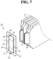
- FIGS. 7 to 9 are diagrams for illustrating each step of connecting the electrode leads of the pouch-type battery cells 10 according to an embodiment of the present disclosure to the bus bar assembly 20.
- the battery module of the present disclosure may further include a bus bar assembly 20 for electrically connecting the positive electrode lead group 18 and the negative electrode lead group 19.
- the bus bar assembly 20 may include a fixed bus bar 21, a pair of movable bus bars 22, and a contact portion 23 for allowing the pair of movable bus bars 22 to be movable relative to the fixed bus bar 21.
- the positive electrode lead group 18 and the negative electrode lead group 19 may be inserted into a fitting space S of the bus bar assembly 20, and subsequently, clamped and welded thereto.
- the bending process of the electrode lead is unnecessary, and therefore, the automation ratio of the production line may be increased.
- the electrode lead groups may be welded under mechanical compression. Thus, even when two or more electrode leads are joined in parallel, it is possible to maintain the reliability of electrical connection and the mechanical bonding strength.
- bus bar assembly 20 according to the present disclosure will be described in more detail.
- the fixed bus bar 21 may be formed as a rod-shaped and made of an electrically conductive material such as copper, silver, and tin-plated copper. Thus, when the positive electrode lead group 18 and the negative electrode lead group 19 contact the fixed bus bar 21, the current of the battery module may stably flow.
- the movable bus bar 22 may also be made of a metal with electrical conductivity such as copper, silver, tinned copper, or copper, similar to the fixed bus bar 21. However, the movable bus bar 22 has a main function of pressing the positive electrode lead group 18 and the negative electrode lead group 19 to be adhered to the fixed bus bar 21 and be clamped. Thus, it may be unnecessary to make the movable bus bar 22 with a metal material, and the movable bus bar 22 may be made of a non-metallic material.
- the movable bus bar 22 is provided in a pair to be movable relative to the fixed bus bar 21 interposed therebetween.
- a fitting space S is provided between the movable bus bar 22 and the fixed bus bar 21 to allow the positive electrode lead group 18 or the negative electrode lead group 19 to pass therethrough.
- the negative electrode lead group 19 may be inserted in the fitting space S between the left movable bus bar 22 and the fixed bus bar 21, and the positive electrode lead group 18 may be inserted in the fitting space S between the right movable bus bar 22 and the fixed bus bar 21.
- Each of the pair of movable bus bars 22 includes an contact portion 23 and a gap adjusting portion 24 that form a substantially square bracket shape and may be symmetrically disposed about the fixed bus bar 21 to surround the fixed bus bar.
- the contact portion 23 may be defined as a portion disposed in parallel to the fixed bus bar 21, and the gap adjusting portion 24 may be defined as a portion bent and extending from both ends of the contact portion 23 toward the fixed bus bar 21.
- the gap adjusting portion 24 of the left movable bus bar 22 and the gap adjusting portion 24 of the right movable bus bar 22 are configured to contact each other.
- the width of the fitting space S may be variously designed depending on the length of the gap adjusting portions 24 of the movable bus bars 22 in contact.
- An adhering member 25 may move the pair of movable bus bars 22 toward the fixed bus bar 21.
- a leaf spring is applied as the adhering member 25. Both ends of the leaf spring are coupled to left and right movable bus bar 22 in a state where the leaf spring is closed.
- the left and right movable bus bars 22 are released after being pulled outward by applying an external force, the left and right movable bus bars 22 are moved toward the fixed bus bar 21 into an original state due to the elastic restoring force of the leaf spring.
- the positive electrode lead group 18 and the negative electrode lead group 19 are formed by overlapping one ends of the positive electrode leads 14 and one ends of the negative electrode leads 15, respectively, with respect to the first positive electrode lead 14 and the first negative electrode lead 15 adjacent to each other.
- the left and right movable bus bars 22 of the bus bar assembly 20 are pulled outward to secure the sufficient fitting space S, and in this state, the positive electrode lead group 18 and the negative electrode lead group 19 are inserted into the corresponding fitting space S, respectively.
- the left and right movable bus bars 22 of the bus bar assembly 20 are released to allow the positive electrode lead group 18 and the negative electrode lead group 19 to abut the fixed bus bar 21.
- the positive electrode lead group 18 and the negative electrode lead group 19 may be clamped by the bus bar assembly 20 and be coupled to the fixed bus bar 21 in a linearly extending state. Further, a welding process may be used to more securely bond the positive electrode lead group 18 and the negative electrode lead group 19 to the bus bar assembly 20.
- the process of bending the electrode lead of the prior art is unnecessary during the electrode lead welding process.
- the manual process for bending the electrode leads may be eliminated to improve the automation ratio of the battery module production line.
- all of the electrode leads may be welded in a mechanically compressed state, the electrical connectivity and the reliability of mechanical bonding strength may be improved regardless of the number of the electrode leads in the parallel connection structure.
- a battery pack according to the present disclosure may include at least one battery modules of the present disclosure.
- the battery pack according to the present disclosure may further include a pack case for accommodating the battery module, various devices for controlling charge and discharge of each battery module, and the like.
Description
- The present application claims the benefit of priority to Korean Patent Application No.
10-2017-0158519 filed on November 24, 2017 - The present disclosure relates to a battery module, and more particularly, to a battery module capable of preventing an electric contact between a pouch case and an electrode lead in pouch-type battery cells connected in parallel within the battery module and improving bonding stability between a bus bar and a plurality of electrode leads overlapped in multiple layers at a parallel connection structure.
- Generally, lithium secondary batteries may be classified into a can-type secondary battery in which an electrode assembly is included in a metal can and a pouch-type secondary battery in which an electrode assembly is included in a pouch made of an aluminum sheet, depending on the exterior shape.
- Recently, secondary batteries have been widely used not only in small-sized devices such as portable electronic devices, but also in electric vehicles that require an operating power using internal combustion engines and/or electric motors. The electric vehicles include hybrid electric vehicles, plug-in hybrid electric vehicles, and pure electric vehicles powered by an electric motor and a battery without an internal combustion engine.
- In the electric vehicles, a large number of secondary batteries are electrically connected to increase capacity and power. In particular, pouch-type secondary batteries are widely used for the mid-to-large-sized devices since they are easily stacked. For example, typically, the battery modules of the mid-to-large-sized devices are implemented by stacking the pouch-type secondary batteries and connecting the electrode leads in series and/or in parallel.
- Meanwhile, as shown in
FIG. 1 , when pouch-type battery cells bus bar 4. Subsequently, the end portions are welded together to be bonded in this state. - However, when the pouch-type battery cells are connected in parallel as above, as shown in
FIG. 2 , apositive electrode lead 1a of one pouch-type battery cell 1 frequently interferes with a terracefront end 2b of a pouch case of another pouch-type battery cell 2 adjacent thereto. The pouch case has a layered structure in which anouter insulation layer 7, analuminum layer 6, and aninner adhesion layer 5 are laminated in order. The electrode lead is allowed to contact theouter insulation layer 7 of the pouch case, but an electric short may occur when the electrode contacts theterrace front end 2b at which thealuminum layer 6 may be exposed. In other words, when the positive electrode lead 1a contacts thealuminum layer 6 of the pouch case in a state where the insulation of the pouch case is broken, a short circuit may occur, which greatly increase the possibility of ignition. - In other words, the pouch-type secondary battery may be somewhat vulnerable to an external physical impact due to its configuration. Thus, unless thermal bonding is performed precisely during the sealing process, the vulnerability may become more serious so that a crack or a damage may occur in the
inner adhesion layer 5 merely with a minor physical impact, thereby converting thealuminum layer 6 into an electrode. When theinner adhesion layer 5 is damaged, thealuminum layer 6 may be polarized since it is in direct contact with the electrode assembly. In general, since the negative electrode plate is disposed at an outermost side of the electrode assembly, thealuminum layer 6 becomes a negative electrode. In a state where thealuminum layer 6 becomes a negative electrode, when thepositive electrode lead 1a contacts the terracefront end 2b of the pouch case as shown inFIG. 2 , a short circuit may occur, which may lead to ignition of the pouch-type secondary battery. - Thus, especially when multiple pouch-type secondary batteries are connected in parallel, it is needed to provide an insulating means that isolates the electrode lead from the terrace front end of the pouch case. For example, in a conventional battery module process, an additional insulating sheet or insulation tape is applied between adjacent pouch-type battery cells, or an injection-molded component is additionally assembled. However, these solutions cause other problems such as an increased cost and a complicated assembly process.
- In addition, in the conventional technique, a large number of manual operations are required to weld the electrode leads to the bus bar, and the electrode leads and the bus bar are not easily adhered to each other due to the elastic restoration force of the electrode leads made of a metallic material. In particular, when three or more electrode leads are connected in parallel, a plurality of electrode leads should be overlapped on the bus bar, which makes the welding work more difficult and deteriorates the welding quality.
- Further,
US 2016/226043 relates to a battery module, wherein electrode leads of the battery cells have a damping structure. - The present disclosure is directed to providing a battery module, which may prevent an electric contact between an electrode lead and a terrace front end of a pouch case in adjacent pouch-type battery cells among a plurality of pouch-type battery cells connected in parallel and may also improve bonding stability between a plurality of electrode leads and a bus bar overlapped in plural layers in a parallel connection structure.
- The solution is provided by the subject matter of claim 1. Preferred embodiments are claimed in dependent claims.
- In one aspect of the present disclosure, there is provided a battery module comprising pouch-type battery cells stacked on each other and electrically connected in series and/or in parallel. Toward an electrode lead of one pouch-type battery cell, electrode leads of other pouch-type battery cells are biased to allow ends of the electrode leads to be overlapped, and each of the pouch-type battery cells include an R bending portion at which a boundary region between a terrace of a pouch case and the electrode leads is bent toward a direction in which the electrode leads are biased.
- The R bending portion has a rounded recess shape, and the terrace may be bent to allow a front end thereof is disposed near a deepest region of the rounded recess shape of the R bending portion.
- The battery module may comprise a positive electrode lead group in which ends of at least two positive electrode leads are overlapped and linearly extend; and a negative electrode lead group in which ends of at least two negative electrode leads provided in a same number as the positive electrode leads are overlapped and linearly extend in a same direction as the positive electrode lead group. With respect to a first positive electrode lead and a first negative electrode lead that face each other at a shortest distance among the positive electrode lead group and the negative electrode lead group, other positive electrode leads may be biased toward the first positive electrode lead, and other negative electrode leads may be biased toward the first negative electrode lead.
- The battery module may comprise a bus bar assembly configured to electrically connect the positive electrode lead group and the negative electrode lead group. In particular, the bus bar assembly may include a fixed bus bar formed in a rod-shaped conductor; a pair of movable bus bars disposed to be spaced apart from each other at both sides of the fixed bus bar with the fixed bus bar interposed therebetween to form a fitting space between the movable bus bars and the fixed bus bar for the positive electrode lead group and the negative electrode lead group to be respectively inserted therein; and an adhering member configured to move the pair of movable bus bars toward the fixed bus bar with the positive electrode lead group and the negative electrode lead group disposed in the fitting space to allow the positive electrode lead group and the negative electrode lead group to be coupled to the fixed bus bar.
- The adhering member may be a leaf spring having both ends coupled to the pair of movable bus bars to move the pair of movable bus bars in directions facing each other due to an elastic restoring force thereof.
- Each of the pair of movable bus bars may include a contact portion provided in parallel to the fixed bus bar; and gap adjusting portions that extend from both ends of the contact portion and are bent, and the gap adjusting portion may be connected to the adhering member. The pair of movable bus bars may be disposed symmetrically with respect to the fixed bus bar to surround the fixed bus bar.
- In another aspect of the present disclosure, there is also provided a battery pack, comprising the battery module described above.
- According to an aspect of the present disclosure, an electric contact between the electrode lead and the terrace front end of the pouch case in adjacent pouch-type battery cells among a plurality of pouch-type battery cells connected in parallel may be prevented, and therefore, safety may be improved.
- In particular, according to an aspect of the present disclosure, since there is no problem such as an increased cost and a complicated assembly process, the high efficiency is ensured compared to where a separate component or insulating taping is used in order to prevent an electrical short between the electrode lead and the pouch case.
- In addition, according to another aspect of the present disclosure, since all of the electrode leads may be welded in a mechanically compressed state, reliability for the electrical connection and the mechanical bonding strength may be improved regardless of the number of electrode leads in a parallel connection structure.
- Moreover, since the manual process for bending terminal portions of the electrode leads is eliminated, the automation rate of the battery module production line may be improved.
- The effects of the present disclosure are not limited to the above, and effects not mentioned herein may be clearly understood from the present specification and the accompanying drawings by those skilled in the art.
-
-
FIG. 1 is a diagram schematically showing that several pouch-type battery cells according to the prior art are connected in parallel. -
FIG. 2 is an enlarged view showing a portion A ofFIG. 1 . -
FIG. 3 is a diagram schematically showing a pouch-type battery cell according to an embodiment of the present disclosure. -
FIGS. 4 and5 are a perspective view and a cross-sectioned view, respectively, schematically showing that multiple pouch-type battery cells according to an embodiment of the present disclosure are connected in parallel. -
FIG. 6 is an enlarged view showing a portion B ofFIG. 5 . -
FIGS. 7 to 9 are diagrams for illustrating each step of connecting electrode leads of the pouch-type battery cells according to an embodiment of the present disclosure to a bus bar assembly. - Hereinafter, preferred embodiments of the present disclosure will be described in detail with reference to the accompanying drawings. Prior to the description, it should be understood that the terms used in the specification and the appended claims should not be construed as limited to general and dictionary meanings, but interpreted based on the meanings and concepts corresponding to technical aspects of the present disclosure on the basis of the principle that the inventor is allowed to define terms appropriately for the best explanation.
- Therefore, the description proposed herein is just a preferable example for the purpose of illustrations only, not intended to limit the scope of the disclosure, so it should be understood that other equivalents and modifications could be made thereto without departing from the scope of the disclosure.
- The embodiments disclosed herein are provided for more perfect explanation of the present disclosure, and thus the shape, size and the like of components may be exaggerated, omitted or simplified in the drawings for better understanding. Thus, the size and ratio of components in the drawings do not wholly reflect the actual size and ratio.
- A battery module according to the present disclosure includes a cell stack having pouch-
type battery cells 10 stacked in one direction and electrically connected in series and/or in parallel, a voltage sensing assembly for electrically connecting the cell stack and sensing a voltage of the cell stack, a module housing for accommodating the cell stack to be protected from exterior elements and providing a mechanical support to the cell stack, and various devices for controlling charge and discharge of the pouch-type battery cells 10 such as a battery management system (BMS), a current sensor, a fuse, and the like. In the following disclosure, any configuration that may blur the gist of the present disclosure will not be explained, and characteristic features of the present disclosure will be described in detail. -
FIG. 3 is a diagram schematically showing a pouch-type battery cell 10 according to an embodiment of the present disclosure. - First, referring to
FIG. 3 , a pouch-type battery cell 10 applied to the battery module according to the present disclosure includes anelectrode assembly 13, a pouch case, and an electrode lead having one end connected to theelectrode assembly 13 and the other end that extends out of the pouch case. For reference, a part of the electrode lead is thermally bonded together with the pouch case. In particular, since the thermal bonding layer of the pouch case is made of a resin layer and the electrode lead is made of a metal, the thermal bonding between the electrode lead and the pouch case may be insufficient. In order to supplement the thermal bonding, anadhesive tape 16 may be used. The electrode lead may be thermally bonded to the pouch case in a state where its periphery is taped with theadhesive tape 16. - Although not shown in detail for the sake of convenience of illustration, the
electrode assembly 13 may include a positive electrode plate, a separator, and a negative electrode plate, and may be configured so that the positive electrode plate and the negative electrode plate respectively coated with a positive electrode active material and a negative electrode active material are repeatedly laminated with the separator interposed therebetween. Generally, the negative electrode plate is slightly larger in size than the positive electrode plate and thus is disposed at the top and bottom ends of theelectrode assembly 13. Theelectrode assembly 13 may be accommodated in the pouch case together with an electrolyte in a sealed state. - The pouch case has a multi-layered structure in which a polyolefin resin layer that is a thermal bonding layer serving as a sealing material, a substrate for maintaining mechanical strength, an aluminum (AL) layer that is a metal layer for blocking moisture and oxygen, and a nylon layer that serves as a protective layer are laminated. Casted polypropylene (CPP) is often used as the polyolefin resin layer that serves as a thermal bonding layer.
- The pouch case is provided so that its edges are sealed after the
electrode assembly 13 is accommodated therein and an electrolyte is injected therein. For example, the pouch case includes afirst pouch sheet 11a and asecond pouch sheet 11b. In particular, thefirst pouch sheet 11a may be formed to accommodate theelectrode assembly 13 in a central region thereof, and thesecond pouch sheet 11b may be provided to face the first pouch sheet 1 la to allow their edges to be thermally bonded to each other. Hereinafter, the thermally bonded edge region of the pouch case is defined as aterrace 12. - In particular, referring to
FIGS. 3-6 together, each of the pouch-type battery cells 10 of the battery module according to the present disclosure further includes anR bending portion 17. TheR bending portion 17 is a portion prepared by bending a boundary region between theterrace 12 of the pouch exterior and the electrode lead. When multiple pouch-type battery cells 10 are connected in parallel, theR bending portion 17 prevents the electrode lead and a terracefront end 12a of the pouch exterior from interfering with each other or from contacting each other. - More specifically, referring to the
R bending portion 17, the terracefront end 12a of the pouch case is disposed at a position where theR bending portion 17 is sharply bent compared to other portions to deviate from a linear line along which the electrode lead extends from theterrace 12 of the pouch exterior. - In this embodiment, the
R bending portion 17 may have a rounded or arc recess shape in a region before and after the boundary region between theterrace 12 of the pouch exterior and the electrode lead. In particular, the terracefront end 12a of the pouch exterior is preferably disposed at a deepest region of the recess shape of theR bending portion 17. - In addition, as shown in
FIGS. 4 and5 , theR bending portion 17 is formed in a same direction as the direction in which, based on an electrode lead of one pouch-type battery cell 10, electrode leads of other pouch-type battery cells 10 are biased when several pouch-type battery cells 10 are connected in parallel. - For example, in this embodiment, it is assumed that among six pouch-
type battery cells 10 in total, three pouch-type battery cells 10 are connected in parallel, respectively. In this case, positive electrode leads 14 of the first and second pouch-type battery cells 10, counted from the left side ofFIG. 5 , may be biased to the right side to overlap with apositive electrode lead 14 of the third pouch-type battery cell 10 as a reference. Accordingly, theR bending portions 17 of the three left pouch-type battery cells 10 are oriented to the right, which corresponds to the direction in which the positive electrode leads 14 are biased. On the contrary, negative electrode leads 15 of the fifth and sixth pouch-type battery cells 10, counted from the left side ofFIG. 5 , may be biased to the left side to overlap with anegative electrode lead 15 of the fourth pouch-type battery cell 10 as a reference. Accordingly, theR bending portions 17 of the three right pouch-type battery cells 10 are oriented to the left. - Due to the
R bending portions 17 of the pouch-type battery cells 10, when the pouch-type battery cells 10 are connected in parallel, as shown inFIG. 6 , even though an electrode lead of any one pouch-type battery cell 10 is biased at any angle, the electrode lead may be prevented from interfering with or contacting the terracefront end 12a of another pouch-type battery cell 10. Thus, when the pouch-type battery cells 10 are connected in parallel, due to theR bending portion 17 of the present disclosure, unlike the prior art where a separate component or an insulating tape is provided, the possibility of electric contact between the electrode lead and the metal layer of the pouch exterior may be efficiently eliminated. - Meanwhile, the pouch-
type battery cells 10 of the battery module according to the present disclosure have a positiveelectrode lead group 18 in which one ends of at least two positive electrode leads 14 extend linearly, and a negativeelectrode lead group 19 in which negative electrode leads provided in the same number as the positive electrode leads 14 extend linearly in the same direction as the positiveelectrode lead group 18. - With respect to a first
positive electrode lead 14 and a firstnegative electrode lead 15 that face each other at a shortest distance among the positiveelectrode lead group 18 and the negativeelectrode lead group 19, other positive electrode leads 14 may be biased toward the firstpositive electrode lead 14, and other negative electrode leads 15 may be biased toward the firstnegative electrode lead 15. Although only one side of the pouch-type battery cells 10 connected in parallel is illustrated in the figures for an example, the opposite side of the pouch-type battery cells 10 may have the same structure, even though its polarity is different, and thus it will not be described in detail again. - For example, in the pouch-
type battery cells 10 depicted inFIGS. 4 and5 , the firstpositive electrode lead 14 may correspond to thepositive electrode lead 14 of the third pouch-type battery cell 10, counted from the left side on the figures, and the firstnegative electrode lead 15 may correspond to thenegative electrode lead 15 of the fourth pouch-type battery cell 10. In this configuration, the gap between the positiveelectrode lead group 18 and the negativeelectrode lead group 19 may be minimized, which makes it easier to connect the positiveelectrode lead group 18 and the negativeelectrode lead group 19 to a bus bar later. - The positive
electrode lead group 18 and the negativeelectrode lead group 19 according to the present disclosure may be coupled to thebus bar assembly 20, to be explained later, in a linearly extending form. -
FIGS. 7 to 9 are diagrams for illustrating each step of connecting the electrode leads of the pouch-type battery cells 10 according to an embodiment of the present disclosure to thebus bar assembly 20. - Referring to
FIGS. 7 to 9 , the battery module of the present disclosure may further include abus bar assembly 20 for electrically connecting the positiveelectrode lead group 18 and the negativeelectrode lead group 19. - The
bus bar assembly 20 may include a fixedbus bar 21, a pair of movable bus bars 22, and acontact portion 23 for allowing the pair of movable bus bars 22 to be movable relative to the fixedbus bar 21. - As will be described in more detail below, according to the present disclosure, the positive
electrode lead group 18 and the negativeelectrode lead group 19 may be inserted into a fitting space S of thebus bar assembly 20, and subsequently, clamped and welded thereto. Thus, unlike the prior art, the bending process of the electrode lead is unnecessary, and therefore, the automation ratio of the production line may be increased. In addition, according to the present disclosure, the electrode lead groups may be welded under mechanical compression. Thus, even when two or more electrode leads are joined in parallel, it is possible to maintain the reliability of electrical connection and the mechanical bonding strength. - Hereinafter, the
bus bar assembly 20 according to the present disclosure will be described in more detail. - The fixed
bus bar 21 may be formed as a rod-shaped and made of an electrically conductive material such as copper, silver, and tin-plated copper. Thus, when the positiveelectrode lead group 18 and the negativeelectrode lead group 19 contact the fixedbus bar 21, the current of the battery module may stably flow. - The
movable bus bar 22 may also be made of a metal with electrical conductivity such as copper, silver, tinned copper, or copper, similar to the fixedbus bar 21. However, themovable bus bar 22 has a main function of pressing the positiveelectrode lead group 18 and the negativeelectrode lead group 19 to be adhered to the fixedbus bar 21 and be clamped. Thus, it may be unnecessary to make themovable bus bar 22 with a metal material, and themovable bus bar 22 may be made of a non-metallic material. - The
movable bus bar 22 is provided in a pair to be movable relative to the fixedbus bar 21 interposed therebetween. In addition, a fitting space S is provided between themovable bus bar 22 and the fixedbus bar 21 to allow the positiveelectrode lead group 18 or the negativeelectrode lead group 19 to pass therethrough. For example, as shown inFIGS. 7 and8 , the negativeelectrode lead group 19 may be inserted in the fitting space S between the leftmovable bus bar 22 and the fixedbus bar 21, and the positiveelectrode lead group 18 may be inserted in the fitting space S between the rightmovable bus bar 22 and the fixedbus bar 21. - Each of the pair of movable bus bars 22 according to this embodiment includes an
contact portion 23 and agap adjusting portion 24 that form a substantially square bracket shape and may be symmetrically disposed about the fixedbus bar 21 to surround the fixed bus bar. Thecontact portion 23 may be defined as a portion disposed in parallel to the fixedbus bar 21, and thegap adjusting portion 24 may be defined as a portion bent and extending from both ends of thecontact portion 23 toward the fixedbus bar 21. - The
gap adjusting portion 24 of the leftmovable bus bar 22 and thegap adjusting portion 24 of the rightmovable bus bar 22 are configured to contact each other. The width of the fitting space S may be variously designed depending on the length of thegap adjusting portions 24 of the movable bus bars 22 in contact. - An adhering
member 25 may move the pair of movable bus bars 22 toward the fixedbus bar 21. In this embodiment, a leaf spring is applied as the adheringmember 25. Both ends of the leaf spring are coupled to left and rightmovable bus bar 22 in a state where the leaf spring is closed. Thus, when the left and right movable bus bars 22 are released after being pulled outward by applying an external force, the left and right movable bus bars 22 are moved toward the fixedbus bar 21 into an original state due to the elastic restoring force of the leaf spring. - Hereinafter, a process of bonding the positive
electrode lead group 18 and the negativeelectrode lead group 19 connected in parallel to thebus bar assembly 20 will be briefly described with reference toFIGS. 7 to 9 . - First, the positive
electrode lead group 18 and the negativeelectrode lead group 19 are formed by overlapping one ends of the positive electrode leads 14 and one ends of the negative electrode leads 15, respectively, with respect to the firstpositive electrode lead 14 and the firstnegative electrode lead 15 adjacent to each other. - Subsequently, the left and right movable bus bars 22 of the
bus bar assembly 20 are pulled outward to secure the sufficient fitting space S, and in this state, the positiveelectrode lead group 18 and the negativeelectrode lead group 19 are inserted into the corresponding fitting space S, respectively. - Thereafter, the left and right movable bus bars 22 of the
bus bar assembly 20 are released to allow the positiveelectrode lead group 18 and the negativeelectrode lead group 19 to abut the fixedbus bar 21. The positiveelectrode lead group 18 and the negativeelectrode lead group 19 may be clamped by thebus bar assembly 20 and be coupled to the fixedbus bar 21 in a linearly extending state. Further, a welding process may be used to more securely bond the positiveelectrode lead group 18 and the negativeelectrode lead group 19 to thebus bar assembly 20. - According to the
bus bar assembly 20 of the present disclosure, the process of bending the electrode lead of the prior art (seeFIG. 1 ) is unnecessary during the electrode lead welding process. Thus, the manual process for bending the electrode leads may be eliminated to improve the automation ratio of the battery module production line. In addition, since all of the electrode leads may be welded in a mechanically compressed state, the electrical connectivity and the reliability of mechanical bonding strength may be improved regardless of the number of the electrode leads in the parallel connection structure. - A battery pack according to the present disclosure may include at least one battery modules of the present disclosure. In addition to the battery module, the battery pack according to the present disclosure may further include a pack case for accommodating the battery module, various devices for controlling charge and discharge of each battery module, and the like.
- The present disclosure has been described in detail. However, it should be understood that the detailed description and specific examples, while indicating preferred embodiments of the disclosure, are given by way of illustration only.
- Meanwhile, when the terms indicating up, down, left, and right directions are used in the specification, it is obvious to those skilled in the art that these merely represent relative positions for convenience in explanation and may vary based on a location of an observer or an object to be observed.
Claims (6)
- A battery module, comprising pouch-type battery cells (10) stacked on each other and electrically connected in series and/or in parallel,wherein toward an electrode lead (14, 15) of one pouch-type battery cell (10), electrode leads (14, 15) of other pouch-type battery cells (10) are biased to allow ends of the electrode leads (14, 15) to be overlapped, andwherein each of the pouch-type battery cells (10) includes an R bending portion (17) at which a boundary region between a thermally bonded edge region (12) of a pouch case and the electrode lead (14, 15) is bent toward a direction in which the electrode leads (14, 15) are biased, wherein the R bending portion (17) is formed in a rounded recess shape, and the thermally bonded edge region (12) is bent to allow a front end thereof to be disposed near a deepest region of the rounded recess shape of the R bending portion (17).
- The battery module according to claim 1, comprising:a positive electrode lead group (18) in which ends of at least two positive electrode leads (14) are overlapped and linearly extend; anda negative electrode lead group (19) in which ends of at least two negative electrode leads (15) provided in a same number as the positive electrode leads (14) are overlapped and linearly extend in a same direction as the positive electrode lead group (18),wherein, with respect to a first positive electrode lead (14) and a first negative electrode lead (15) that face each other at a shortest distance among the positive electrode lead group (18) and the negative electrode lead group (19), other positive electrode leads (14) are biased toward the first positive electrode lead (14), and other negative electrode leads (15) are biased toward the first negative electrode lead (15).
- The battery module according to claim 2, further comprising:
a bus bar assembly (20) configured to electrically connect the positive electrode lead group (18) and the negative electrode lead group (19), wherein the bus bar assembly (20) includes:a fixed bus bar (21) formed in a rod-shaped conductor;a pair of movable bus bars (22) disposed to be spaced apart from each other at both sides of the fixed bus bar (21) with the fixed bus bar (21) interposed therebetween to form a fitting space (S) between the movable bus bars (22) and the fixed bus bar (21) to allow the positive electrode lead group (18) and the negative electrode lead group (19) to be respectively inserted therein; andan adhering member (25) configured to move the pair of movable bus bars (22) toward the fixed bus bar (21) with the positive electrode lead group (18) and the negative electrode lead group (19) disposed in the fitting space (S) to allow the positive electrode lead group (18) and the negative electrode lead group (19) to be coupled to the fixed bus bar (21). - The battery module according to claim 3, wherein the adhering member (25) is a leaf spring having both ends coupled to the pair of movable bus bars (22) to move the pair of movable bus bars (22) in directions facing each other due to an elastic restoring force thereof.
- The battery module according to claim 3, wherein each of the pair of movable bus bars includes:a contact portion (23) provided in parallel to the fixed bus bar (21); andgap adjusting portions (24) that extend from both ends of the contact portion (23) and are bent, the gas adjusting portions (24) connected to the adhering member (25),wherein the pair of movable bus bars (22) are disposed symmetrically with respect to the fixed bus bar (21) to surround the fixed bus bar (21).
- A battery pack, comprising a battery module defined in any one of claims 1 to 5.
Priority Applications (1)
| Application Number | Priority Date | Filing Date | Title |
|---|---|---|---|
| PL18881818T PL3624227T3 (en) | 2017-11-24 | 2018-10-31 | Battery module having enhanced electrical connection stability |
Applications Claiming Priority (2)
| Application Number | Priority Date | Filing Date | Title |
|---|---|---|---|
| KR1020170158519A KR102258819B1 (en) | 2017-11-24 | 2017-11-24 | Battery Module with improved electrical connection safety |
| PCT/KR2018/013133 WO2019103344A1 (en) | 2017-11-24 | 2018-10-31 | Battery module having enhanced electrical connection stability |
Publications (3)
| Publication Number | Publication Date |
|---|---|
| EP3624227A1 EP3624227A1 (en) | 2020-03-18 |
| EP3624227A4 EP3624227A4 (en) | 2020-08-12 |
| EP3624227B1 true EP3624227B1 (en) | 2021-06-02 |
Family
ID=66631067
Family Applications (1)
| Application Number | Title | Priority Date | Filing Date |
|---|---|---|---|
| EP18881818.1A Active EP3624227B1 (en) | 2017-11-24 | 2018-10-31 | Battery module having enhanced electrical connection stability |
Country Status (7)
| Country | Link |
|---|---|
| US (1) | US11217864B2 (en) |
| EP (1) | EP3624227B1 (en) |
| JP (1) | JP6798043B2 (en) |
| KR (1) | KR102258819B1 (en) |
| CN (1) | CN110622341B (en) |
| PL (1) | PL3624227T3 (en) |
| WO (1) | WO2019103344A1 (en) |
Families Citing this family (10)
| Publication number | Priority date | Publication date | Assignee | Title |
|---|---|---|---|---|
| KR102273184B1 (en) * | 2017-10-10 | 2021-07-05 | 주식회사 엘지에너지솔루션 | Bus bar assembly for connecting electrode lead and Battery module including the same |
| KR102320342B1 (en) * | 2018-05-29 | 2021-11-03 | 주식회사 엘지에너지솔루션 | Battery module |
| CN111630689B (en) * | 2018-10-26 | 2022-11-04 | 株式会社Lg新能源 | Battery module having structure capable of preventing damage of battery cells, and battery pack and vehicle including the same |
| JP7115358B2 (en) * | 2019-02-26 | 2022-08-09 | 住友電装株式会社 | electronic module |
| CN111755657B (en) * | 2019-03-29 | 2022-02-15 | 宁德新能源科技有限公司 | Electrode assembly |
| KR102541537B1 (en) * | 2019-06-25 | 2023-06-08 | 주식회사 엘지에너지솔루션 | Battery module and battery pack including the same |
| KR102506245B1 (en) * | 2019-11-14 | 2023-03-03 | 주식회사 엘지에너지솔루션 | Battery module, method of manufacturing battery module and battery pack including battery module |
| KR20220032930A (en) * | 2020-09-08 | 2022-03-15 | 주식회사 엘지에너지솔루션 | Battery cell including electrode leads of asymmetric structure and battery module with reinforced mechanical strength comprising the same |
| CN112151730B (en) * | 2020-09-25 | 2023-02-21 | 飞毛腿(福建)电子有限公司 | Laser welding assembly structure of mobile power supply and assembly process thereof |
| KR20240007501A (en) * | 2022-07-08 | 2024-01-16 | 주식회사 엘지에너지솔루션 | Battery module, battery pack and vehicle including the same |
Family Cites Families (32)
| Publication number | Priority date | Publication date | Assignee | Title |
|---|---|---|---|---|
| KR0158519B1 (en) | 1995-07-01 | 1998-11-16 | 김용진 | Method for cooking miscellaneous in electric pressure rice cooker |
| US6042966A (en) | 1998-01-20 | 2000-03-28 | Valence Technology, Inc. | Battery terminal insulation |
| JP2000021387A (en) | 1998-07-01 | 2000-01-21 | Mitsubishi Cable Ind Ltd | Sheet type battery |
| JP2001256960A (en) | 2000-03-10 | 2001-09-21 | Mitsubishi Chemicals Corp | Battery |
| JP2002298825A (en) | 2001-03-29 | 2002-10-11 | Tdk Corp | Method of producing electrochemical device and the electrochemical device |
| JP2003272572A (en) * | 2002-03-20 | 2003-09-26 | Dainippon Printing Co Ltd | Outerjacketing body for battery and packaging method of battery |
| JP4499977B2 (en) | 2002-05-07 | 2010-07-14 | 富士重工業株式会社 | Plate battery electrode insulation structure |
| EP1394874B1 (en) * | 2002-05-08 | 2006-08-23 | Nissan Motor Co., Ltd. | Secondary cell module and method of its production |
| JP3698320B2 (en) | 2002-06-03 | 2005-09-21 | 日産自動車株式会社 | Assembled battery |
| JP4211322B2 (en) * | 2002-08-26 | 2009-01-21 | 日産自動車株式会社 | Multilayer battery, battery pack, battery module and electric vehicle |
| JP3695435B2 (en) * | 2002-09-03 | 2005-09-14 | 日産自動車株式会社 | Laminated exterior flat battery |
| JP2004158434A (en) | 2002-10-15 | 2004-06-03 | Dainippon Printing Co Ltd | Lithium cell |
| KR20040054128A (en) | 2002-12-17 | 2004-06-25 | 삼성에스디아이 주식회사 | Pouched-type lithium secondary battery |
| JP3789438B2 (en) * | 2003-03-03 | 2006-06-21 | Necラミリオンエナジー株式会社 | Film outer battery |
| KR100502353B1 (en) | 2003-06-12 | 2005-07-21 | 삼성에스디아이 주식회사 | Battery |
| JP2005044583A (en) * | 2003-07-25 | 2005-02-17 | Toshiba Corp | Thin secondary battery |
| JP2007095465A (en) | 2005-09-28 | 2007-04-12 | Sanyo Electric Co Ltd | Sealed battery and method of manufacturing same |
| KR100891078B1 (en) * | 2006-04-03 | 2009-03-30 | 주식회사 엘지화학 | Lithium Secondary Battery Improved Safety and Capacity |
| KR101038680B1 (en) | 2010-03-12 | 2011-06-02 | 아이피지 포토닉스 코리아(주) | Secondary battery and module using the same |
| US20120315531A1 (en) * | 2011-06-10 | 2012-12-13 | GM Global Technology Operations LLC | Battery cell connection apparatus |
| KR101905080B1 (en) | 2011-12-09 | 2018-10-05 | 삼성에스디아이 주식회사 | Battery pack |
| KR102024002B1 (en) * | 2012-07-05 | 2019-09-23 | 에스케이이노베이션 주식회사 | Battery pack |
| JP2014053104A (en) | 2012-09-05 | 2014-03-20 | Captex Co Ltd | Electrode connection structure |
| KR101732285B1 (en) * | 2012-11-09 | 2017-05-02 | 닛산 지도우샤 가부시키가이샤 | Assembled battery and method for manufacturing assembled battery |
| KR101747397B1 (en) * | 2013-09-25 | 2017-06-14 | 주식회사 엘지화학 | Battery Module Having Electrode Lead with Damping Structure |
| US10396334B2 (en) * | 2014-03-31 | 2019-08-27 | Lg Chem, Ltd. | Battery module and battery pack comprising same |
| WO2015152527A1 (en) * | 2014-03-31 | 2015-10-08 | 주식회사 엘지화학 | Battery module and battery pack comprising same |
| KR101736377B1 (en) * | 2014-06-09 | 2017-05-16 | 주식회사 엘지화학 | Battery module and battery pack including the same |
| KR101957311B1 (en) | 2015-07-21 | 2019-03-12 | 주식회사 엘지화학 | Secondary battery |
| US10532423B2 (en) * | 2015-12-09 | 2020-01-14 | Lg Chem, Ltd. | Battery pack and method for manufacturing the same |
| KR102424640B1 (en) | 2015-12-29 | 2022-07-25 | 에이치그린파워 주식회사 | Battery module and Method for assembling the same |
| US10122004B2 (en) * | 2017-03-16 | 2018-11-06 | Ford Global Technologies, Llc | Quick connect assembly for busbars in an electrified vehicle |
-
2017
- 2017-11-24 KR KR1020170158519A patent/KR102258819B1/en active IP Right Grant
-
2018
- 2018-10-31 CN CN201880031997.3A patent/CN110622341B/en active Active
- 2018-10-31 US US16/609,981 patent/US11217864B2/en active Active
- 2018-10-31 JP JP2019559766A patent/JP6798043B2/en active Active
- 2018-10-31 PL PL18881818T patent/PL3624227T3/en unknown
- 2018-10-31 EP EP18881818.1A patent/EP3624227B1/en active Active
- 2018-10-31 WO PCT/KR2018/013133 patent/WO2019103344A1/en unknown
Also Published As
| Publication number | Publication date |
|---|---|
| EP3624227A1 (en) | 2020-03-18 |
| PL3624227T3 (en) | 2021-10-18 |
| KR20190060376A (en) | 2019-06-03 |
| US20200067066A1 (en) | 2020-02-27 |
| WO2019103344A1 (en) | 2019-05-31 |
| CN110622341A (en) | 2019-12-27 |
| KR102258819B1 (en) | 2021-05-31 |
| US11217864B2 (en) | 2022-01-04 |
| JP6798043B2 (en) | 2020-12-09 |
| EP3624227A4 (en) | 2020-08-12 |
| JP2020518970A (en) | 2020-06-25 |
| CN110622341B (en) | 2022-04-08 |
Similar Documents
| Publication | Publication Date | Title |
|---|---|---|
| EP3624227B1 (en) | Battery module having enhanced electrical connection stability | |
| EP2736097B1 (en) | Rechargeable battery and module of the same | |
| US9640792B2 (en) | Battery assembly having single electrode terminal connection part | |
| US11289776B2 (en) | Battery module having bus bar assembly | |
| KR102434771B1 (en) | Battery pack | |
| KR101264495B1 (en) | Secondary Battery And Battery Pack having thereof | |
| EP2337118A1 (en) | Secondary battery | |
| KR101472167B1 (en) | Pouch of improved safety for secondary battery and secondary battery, battery pack using the same | |
| KR102263200B1 (en) | Battery Pack | |
| EP3514858A1 (en) | Secondary battery | |
| CN113178656B (en) | battery module | |
| KR20130135063A (en) | Rechargeable battery pack | |
| KR101255245B1 (en) | Battery pack | |
| US9224989B2 (en) | Rechargeable battery and module thereof | |
| KR101652653B1 (en) | Battery module and battery pack | |
| US20210376406A1 (en) | Solid-state battery module and solid-state battery cell | |
| KR101734327B1 (en) | Pouch type secondary battery | |
| EP3664191A1 (en) | Electrode assembly comprising plastic member applied to electrode tab-lead joint part and secondary battery containing same | |
| US10320035B2 (en) | Battery pack | |
| EP3537506B1 (en) | Rechargeable battery | |
| JP2024506457A (en) | Pouch-type battery cells with improved safety and battery modules containing the same | |
| CN116711137A (en) | Pouch-shaped battery cell having improved thermal stability |
Legal Events
| Date | Code | Title | Description |
|---|---|---|---|
| STAA | Information on the status of an ep patent application or granted ep patent |
Free format text: STATUS: THE INTERNATIONAL PUBLICATION HAS BEEN MADE |
|
| PUAI | Public reference made under article 153(3) epc to a published international application that has entered the european phase |
Free format text: ORIGINAL CODE: 0009012 |
|
| STAA | Information on the status of an ep patent application or granted ep patent |
Free format text: STATUS: REQUEST FOR EXAMINATION WAS MADE |
|
| 17P | Request for examination filed |
Effective date: 20191210 |
|
| AK | Designated contracting states |
Kind code of ref document: A1 Designated state(s): AL AT BE BG CH CY CZ DE DK EE ES FI FR GB GR HR HU IE IS IT LI LT LU LV MC MK MT NL NO PL PT RO RS SE SI SK SM TR |
|
| AX | Request for extension of the european patent |
Extension state: BA ME |
|
| A4 | Supplementary search report drawn up and despatched |
Effective date: 20200709 |
|
| RIC1 | Information provided on ipc code assigned before grant |
Ipc: H01M 2/06 20060101ALI20200704BHEP Ipc: H01M 2/30 20060101ALI20200704BHEP Ipc: H01M 2/34 20060101ALI20200704BHEP Ipc: H01M 2/02 20060101ALI20200704BHEP Ipc: H01M 2/20 20060101AFI20200704BHEP Ipc: H01M 2/26 20060101ALI20200704BHEP Ipc: H01M 2/10 20060101ALI20200704BHEP |
|
| REG | Reference to a national code |
Ref country code: DE Ref legal event code: R079 Ref document number: 602018018200 Country of ref document: DE Free format text: PREVIOUS MAIN CLASS: H01M0002200000 Ipc: H01M0050116000 |
|
| DAV | Request for validation of the european patent (deleted) | ||
| DAX | Request for extension of the european patent (deleted) | ||
| GRAP | Despatch of communication of intention to grant a patent |
Free format text: ORIGINAL CODE: EPIDOSNIGR1 |
|
| STAA | Information on the status of an ep patent application or granted ep patent |
Free format text: STATUS: GRANT OF PATENT IS INTENDED |
|
| RIC1 | Information provided on ipc code assigned before grant |
Ipc: H01M 50/20 20210101ALI20210219BHEP Ipc: H01M 50/116 20210101AFI20210219BHEP Ipc: H01M 50/502 20210101ALI20210219BHEP Ipc: H01M 50/543 20210101ALI20210219BHEP Ipc: H01M 50/172 20210101ALI20210219BHEP Ipc: H01M 50/579 20210101ALI20210219BHEP |
|
| INTG | Intention to grant announced |
Effective date: 20210325 |
|
| GRAS | Grant fee paid |
Free format text: ORIGINAL CODE: EPIDOSNIGR3 |
|
| GRAA | (expected) grant |
Free format text: ORIGINAL CODE: 0009210 |
|
| STAA | Information on the status of an ep patent application or granted ep patent |
Free format text: STATUS: THE PATENT HAS BEEN GRANTED |
|
| REG | Reference to a national code |
Ref country code: CH Ref legal event code: EP |
|
| AK | Designated contracting states |
Kind code of ref document: B1 Designated state(s): AL AT BE BG CH CY CZ DE DK EE ES FI FR GB GR HR HU IE IS IT LI LT LU LV MC MK MT NL NO PL PT RO RS SE SI SK SM TR |
|
| REG | Reference to a national code |
Ref country code: GB Ref legal event code: FG4D |
|
| REG | Reference to a national code |
Ref country code: AT Ref legal event code: REF Ref document number: 1399285 Country of ref document: AT Kind code of ref document: T Effective date: 20210615 |
|
| REG | Reference to a national code |
Ref country code: IE Ref legal event code: FG4D |
|
| REG | Reference to a national code |
Ref country code: DE Ref legal event code: R096 Ref document number: 602018018200 Country of ref document: DE |
|
| REG | Reference to a national code |
Ref country code: SE Ref legal event code: TRGR |
|
| REG | Reference to a national code |
Ref country code: LT Ref legal event code: MG9D |
|
| PG25 | Lapsed in a contracting state [announced via postgrant information from national office to epo] |
Ref country code: FI Free format text: LAPSE BECAUSE OF FAILURE TO SUBMIT A TRANSLATION OF THE DESCRIPTION OR TO PAY THE FEE WITHIN THE PRESCRIBED TIME-LIMIT Effective date: 20210602 Ref country code: HR Free format text: LAPSE BECAUSE OF FAILURE TO SUBMIT A TRANSLATION OF THE DESCRIPTION OR TO PAY THE FEE WITHIN THE PRESCRIBED TIME-LIMIT Effective date: 20210602 Ref country code: LT Free format text: LAPSE BECAUSE OF FAILURE TO SUBMIT A TRANSLATION OF THE DESCRIPTION OR TO PAY THE FEE WITHIN THE PRESCRIBED TIME-LIMIT Effective date: 20210602 Ref country code: BG Free format text: LAPSE BECAUSE OF FAILURE TO SUBMIT A TRANSLATION OF THE DESCRIPTION OR TO PAY THE FEE WITHIN THE PRESCRIBED TIME-LIMIT Effective date: 20210902 |
|
| REG | Reference to a national code |
Ref country code: NL Ref legal event code: MP Effective date: 20210602 |
|
| REG | Reference to a national code |
Ref country code: AT Ref legal event code: MK05 Ref document number: 1399285 Country of ref document: AT Kind code of ref document: T Effective date: 20210602 |
|
| PG25 | Lapsed in a contracting state [announced via postgrant information from national office to epo] |
Ref country code: GR Free format text: LAPSE BECAUSE OF FAILURE TO SUBMIT A TRANSLATION OF THE DESCRIPTION OR TO PAY THE FEE WITHIN THE PRESCRIBED TIME-LIMIT Effective date: 20210903 Ref country code: NO Free format text: LAPSE BECAUSE OF FAILURE TO SUBMIT A TRANSLATION OF THE DESCRIPTION OR TO PAY THE FEE WITHIN THE PRESCRIBED TIME-LIMIT Effective date: 20210902 Ref country code: LV Free format text: LAPSE BECAUSE OF FAILURE TO SUBMIT A TRANSLATION OF THE DESCRIPTION OR TO PAY THE FEE WITHIN THE PRESCRIBED TIME-LIMIT Effective date: 20210602 Ref country code: RS Free format text: LAPSE BECAUSE OF FAILURE TO SUBMIT A TRANSLATION OF THE DESCRIPTION OR TO PAY THE FEE WITHIN THE PRESCRIBED TIME-LIMIT Effective date: 20210602 |
|
| RAP2 | Party data changed (patent owner data changed or rights of a patent transferred) |
Owner name: LG ENERGY SOLUTION LTD. |
|
| PG25 | Lapsed in a contracting state [announced via postgrant information from national office to epo] |
Ref country code: SK Free format text: LAPSE BECAUSE OF FAILURE TO SUBMIT A TRANSLATION OF THE DESCRIPTION OR TO PAY THE FEE WITHIN THE PRESCRIBED TIME-LIMIT Effective date: 20210602 Ref country code: ES Free format text: LAPSE BECAUSE OF FAILURE TO SUBMIT A TRANSLATION OF THE DESCRIPTION OR TO PAY THE FEE WITHIN THE PRESCRIBED TIME-LIMIT Effective date: 20210602 Ref country code: EE Free format text: LAPSE BECAUSE OF FAILURE TO SUBMIT A TRANSLATION OF THE DESCRIPTION OR TO PAY THE FEE WITHIN THE PRESCRIBED TIME-LIMIT Effective date: 20210602 Ref country code: CZ Free format text: LAPSE BECAUSE OF FAILURE TO SUBMIT A TRANSLATION OF THE DESCRIPTION OR TO PAY THE FEE WITHIN THE PRESCRIBED TIME-LIMIT Effective date: 20210602 Ref country code: AT Free format text: LAPSE BECAUSE OF FAILURE TO SUBMIT A TRANSLATION OF THE DESCRIPTION OR TO PAY THE FEE WITHIN THE PRESCRIBED TIME-LIMIT Effective date: 20210602 Ref country code: NL Free format text: LAPSE BECAUSE OF FAILURE TO SUBMIT A TRANSLATION OF THE DESCRIPTION OR TO PAY THE FEE WITHIN THE PRESCRIBED TIME-LIMIT Effective date: 20210602 Ref country code: RO Free format text: LAPSE BECAUSE OF FAILURE TO SUBMIT A TRANSLATION OF THE DESCRIPTION OR TO PAY THE FEE WITHIN THE PRESCRIBED TIME-LIMIT Effective date: 20210602 Ref country code: PT Free format text: LAPSE BECAUSE OF FAILURE TO SUBMIT A TRANSLATION OF THE DESCRIPTION OR TO PAY THE FEE WITHIN THE PRESCRIBED TIME-LIMIT Effective date: 20211004 Ref country code: SM Free format text: LAPSE BECAUSE OF FAILURE TO SUBMIT A TRANSLATION OF THE DESCRIPTION OR TO PAY THE FEE WITHIN THE PRESCRIBED TIME-LIMIT Effective date: 20210602 |
|
| REG | Reference to a national code |
Ref country code: DE Ref legal event code: R097 Ref document number: 602018018200 Country of ref document: DE |
|
| RAP4 | Party data changed (patent owner data changed or rights of a patent transferred) |
Owner name: LG ENERGY SOLUTION, LTD. |
|
| PLBE | No opposition filed within time limit |
Free format text: ORIGINAL CODE: 0009261 |
|
| STAA | Information on the status of an ep patent application or granted ep patent |
Free format text: STATUS: NO OPPOSITION FILED WITHIN TIME LIMIT |
|
| PG25 | Lapsed in a contracting state [announced via postgrant information from national office to epo] |
Ref country code: DK Free format text: LAPSE BECAUSE OF FAILURE TO SUBMIT A TRANSLATION OF THE DESCRIPTION OR TO PAY THE FEE WITHIN THE PRESCRIBED TIME-LIMIT Effective date: 20210602 |
|
| 26N | No opposition filed |
Effective date: 20220303 |
|
| REG | Reference to a national code |
Ref country code: CH Ref legal event code: PL |
|
| PG25 | Lapsed in a contracting state [announced via postgrant information from national office to epo] |
Ref country code: AL Free format text: LAPSE BECAUSE OF FAILURE TO SUBMIT A TRANSLATION OF THE DESCRIPTION OR TO PAY THE FEE WITHIN THE PRESCRIBED TIME-LIMIT Effective date: 20210602 |
|
| REG | Reference to a national code |
Ref country code: BE Ref legal event code: MM Effective date: 20211031 |
|
| PG25 | Lapsed in a contracting state [announced via postgrant information from national office to epo] |
Ref country code: MC Free format text: LAPSE BECAUSE OF FAILURE TO SUBMIT A TRANSLATION OF THE DESCRIPTION OR TO PAY THE FEE WITHIN THE PRESCRIBED TIME-LIMIT Effective date: 20210602 |
|
| PG25 | Lapsed in a contracting state [announced via postgrant information from national office to epo] |
Ref country code: LU Free format text: LAPSE BECAUSE OF NON-PAYMENT OF DUE FEES Effective date: 20211031 Ref country code: IT Free format text: LAPSE BECAUSE OF FAILURE TO SUBMIT A TRANSLATION OF THE DESCRIPTION OR TO PAY THE FEE WITHIN THE PRESCRIBED TIME-LIMIT Effective date: 20210602 Ref country code: BE Free format text: LAPSE BECAUSE OF NON-PAYMENT OF DUE FEES Effective date: 20211031 |
|
| PG25 | Lapsed in a contracting state [announced via postgrant information from national office to epo] |
Ref country code: LI Free format text: LAPSE BECAUSE OF NON-PAYMENT OF DUE FEES Effective date: 20211031 Ref country code: CH Free format text: LAPSE BECAUSE OF NON-PAYMENT OF DUE FEES Effective date: 20211031 |
|
| PG25 | Lapsed in a contracting state [announced via postgrant information from national office to epo] |
Ref country code: IE Free format text: LAPSE BECAUSE OF NON-PAYMENT OF DUE FEES Effective date: 20211031 |
|
| REG | Reference to a national code |
Ref country code: DE Ref legal event code: R081 Ref document number: 602018018200 Country of ref document: DE Owner name: LG ENERGY SOLUTION, LTD., KR Free format text: FORMER OWNER: LG CHEM, LTD., SEOUL, KR |
|
| P01 | Opt-out of the competence of the unified patent court (upc) registered |
Effective date: 20230512 |
|
| PG25 | Lapsed in a contracting state [announced via postgrant information from national office to epo] |
Ref country code: CY Free format text: LAPSE BECAUSE OF FAILURE TO SUBMIT A TRANSLATION OF THE DESCRIPTION OR TO PAY THE FEE WITHIN THE PRESCRIBED TIME-LIMIT Effective date: 20210602 |
|
| PG25 | Lapsed in a contracting state [announced via postgrant information from national office to epo] |
Ref country code: HU Free format text: LAPSE BECAUSE OF FAILURE TO SUBMIT A TRANSLATION OF THE DESCRIPTION OR TO PAY THE FEE WITHIN THE PRESCRIBED TIME-LIMIT; INVALID AB INITIO Effective date: 20181031 |
|
| REG | Reference to a national code |
Ref country code: GB Ref legal event code: 732E Free format text: REGISTERED BETWEEN 20230901 AND 20230906 |
|
| PGFP | Annual fee paid to national office [announced via postgrant information from national office to epo] |
Ref country code: GB Payment date: 20230920 Year of fee payment: 6 |
|
| PGFP | Annual fee paid to national office [announced via postgrant information from national office to epo] |
Ref country code: SE Payment date: 20230921 Year of fee payment: 6 Ref country code: PL Payment date: 20230926 Year of fee payment: 6 Ref country code: FR Payment date: 20230922 Year of fee payment: 6 |
|
| PGFP | Annual fee paid to national office [announced via postgrant information from national office to epo] |
Ref country code: DE Payment date: 20230920 Year of fee payment: 6 |