EP3624173A1 - Chip scale package structure and method of forming the same - Google Patents
Chip scale package structure and method of forming the same Download PDFInfo
- Publication number
- EP3624173A1 EP3624173A1 EP19184181.6A EP19184181A EP3624173A1 EP 3624173 A1 EP3624173 A1 EP 3624173A1 EP 19184181 A EP19184181 A EP 19184181A EP 3624173 A1 EP3624173 A1 EP 3624173A1
- Authority
- EP
- European Patent Office
- Prior art keywords
- insulating layer
- protective insulating
- semiconductor die
- layer
- semiconductor package
- Prior art date
- Legal status (The legal status is an assumption and is not a legal conclusion. Google has not performed a legal analysis and makes no representation as to the accuracy of the status listed.)
- Granted
Links
Images




Classifications
-
- H—ELECTRICITY
- H10—SEMICONDUCTOR DEVICES; ELECTRIC SOLID-STATE DEVICES NOT OTHERWISE PROVIDED FOR
- H10W—GENERIC PACKAGES, INTERCONNECTIONS, CONNECTORS OR OTHER CONSTRUCTIONAL DETAILS OF DEVICES COVERED BY CLASS H10
- H10W20/00—Interconnections in chips, wafers or substrates
- H10W20/40—Interconnections external to wafers or substrates, e.g. back-end-of-line [BEOL] metallisations or vias connecting to gate electrodes
- H10W20/41—Interconnections external to wafers or substrates, e.g. back-end-of-line [BEOL] metallisations or vias connecting to gate electrodes characterised by their conductive parts
- H10W20/435—Cross-sectional shapes or dispositions of interconnections
-
- H—ELECTRICITY
- H10—SEMICONDUCTOR DEVICES; ELECTRIC SOLID-STATE DEVICES NOT OTHERWISE PROVIDED FOR
- H10W—GENERIC PACKAGES, INTERCONNECTIONS, CONNECTORS OR OTHER CONSTRUCTIONAL DETAILS OF DEVICES COVERED BY CLASS H10
- H10W70/00—Package substrates; Interposers; Redistribution layers [RDL]
- H10W70/01—Manufacture or treatment
- H10W70/05—Manufacture or treatment of insulating or insulated package substrates, or of interposers, or of redistribution layers
- H10W70/08—Manufacture or treatment of insulating or insulated package substrates, or of interposers, or of redistribution layers by depositing layers on the chip or wafer, e.g. "chip-first" RDLs
- H10W70/09—Manufacture or treatment of insulating or insulated package substrates, or of interposers, or of redistribution layers by depositing layers on the chip or wafer, e.g. "chip-first" RDLs extending onto an encapsulation that laterally surrounds the chip or wafer, e.g. fan-out wafer level package [FOWLP] RDLs
-
- H—ELECTRICITY
- H10—SEMICONDUCTOR DEVICES; ELECTRIC SOLID-STATE DEVICES NOT OTHERWISE PROVIDED FOR
- H10W—GENERIC PACKAGES, INTERCONNECTIONS, CONNECTORS OR OTHER CONSTRUCTIONAL DETAILS OF DEVICES COVERED BY CLASS H10
- H10W72/00—Interconnections or connectors in packages
- H10W72/01—Manufacture or treatment
- H10W72/0198—Manufacture or treatment batch processes
-
- H—ELECTRICITY
- H10—SEMICONDUCTOR DEVICES; ELECTRIC SOLID-STATE DEVICES NOT OTHERWISE PROVIDED FOR
- H10W—GENERIC PACKAGES, INTERCONNECTIONS, CONNECTORS OR OTHER CONSTRUCTIONAL DETAILS OF DEVICES COVERED BY CLASS H10
- H10W72/00—Interconnections or connectors in packages
- H10W72/20—Bump connectors, e.g. solder bumps or copper pillars; Dummy bumps; Thermal bumps
-
- H—ELECTRICITY
- H10—SEMICONDUCTOR DEVICES; ELECTRIC SOLID-STATE DEVICES NOT OTHERWISE PROVIDED FOR
- H10W—GENERIC PACKAGES, INTERCONNECTIONS, CONNECTORS OR OTHER CONSTRUCTIONAL DETAILS OF DEVICES COVERED BY CLASS H10
- H10W72/00—Interconnections or connectors in packages
- H10W72/30—Die-attach connectors
-
- H—ELECTRICITY
- H10—SEMICONDUCTOR DEVICES; ELECTRIC SOLID-STATE DEVICES NOT OTHERWISE PROVIDED FOR
- H10W—GENERIC PACKAGES, INTERCONNECTIONS, CONNECTORS OR OTHER CONSTRUCTIONAL DETAILS OF DEVICES COVERED BY CLASS H10
- H10W72/00—Interconnections or connectors in packages
- H10W72/90—Bond pads, in general
-
- H—ELECTRICITY
- H10—SEMICONDUCTOR DEVICES; ELECTRIC SOLID-STATE DEVICES NOT OTHERWISE PROVIDED FOR
- H10W—GENERIC PACKAGES, INTERCONNECTIONS, CONNECTORS OR OTHER CONSTRUCTIONAL DETAILS OF DEVICES COVERED BY CLASS H10
- H10W74/00—Encapsulations, e.g. protective coatings
- H10W74/01—Manufacture or treatment
- H10W74/012—Manufacture or treatment of encapsulations on active surfaces of flip-chip devices, e.g. forming underfills
-
- H—ELECTRICITY
- H10—SEMICONDUCTOR DEVICES; ELECTRIC SOLID-STATE DEVICES NOT OTHERWISE PROVIDED FOR
- H10W—GENERIC PACKAGES, INTERCONNECTIONS, CONNECTORS OR OTHER CONSTRUCTIONAL DETAILS OF DEVICES COVERED BY CLASS H10
- H10W74/00—Encapsulations, e.g. protective coatings
- H10W74/01—Manufacture or treatment
- H10W74/014—Manufacture or treatment using batch processing
-
- H—ELECTRICITY
- H10—SEMICONDUCTOR DEVICES; ELECTRIC SOLID-STATE DEVICES NOT OTHERWISE PROVIDED FOR
- H10W—GENERIC PACKAGES, INTERCONNECTIONS, CONNECTORS OR OTHER CONSTRUCTIONAL DETAILS OF DEVICES COVERED BY CLASS H10
- H10W74/00—Encapsulations, e.g. protective coatings
- H10W74/01—Manufacture or treatment
- H10W74/016—Manufacture or treatment using moulds
-
- H—ELECTRICITY
- H10—SEMICONDUCTOR DEVICES; ELECTRIC SOLID-STATE DEVICES NOT OTHERWISE PROVIDED FOR
- H10W—GENERIC PACKAGES, INTERCONNECTIONS, CONNECTORS OR OTHER CONSTRUCTIONAL DETAILS OF DEVICES COVERED BY CLASS H10
- H10W74/00—Encapsulations, e.g. protective coatings
- H10W74/10—Encapsulations, e.g. protective coatings characterised by their shape or disposition
- H10W74/111—Encapsulations, e.g. protective coatings characterised by their shape or disposition the semiconductor body being completely enclosed
- H10W74/114—Encapsulations, e.g. protective coatings characterised by their shape or disposition the semiconductor body being completely enclosed by a substrate and the encapsulations
-
- H—ELECTRICITY
- H10—SEMICONDUCTOR DEVICES; ELECTRIC SOLID-STATE DEVICES NOT OTHERWISE PROVIDED FOR
- H10W—GENERIC PACKAGES, INTERCONNECTIONS, CONNECTORS OR OTHER CONSTRUCTIONAL DETAILS OF DEVICES COVERED BY CLASS H10
- H10W74/00—Encapsulations, e.g. protective coatings
- H10W74/10—Encapsulations, e.g. protective coatings characterised by their shape or disposition
- H10W74/111—Encapsulations, e.g. protective coatings characterised by their shape or disposition the semiconductor body being completely enclosed
- H10W74/129—Encapsulations, e.g. protective coatings characterised by their shape or disposition the semiconductor body being completely enclosed forming a chip-scale package [CSP]
-
- H—ELECTRICITY
- H10—SEMICONDUCTOR DEVICES; ELECTRIC SOLID-STATE DEVICES NOT OTHERWISE PROVIDED FOR
- H10W—GENERIC PACKAGES, INTERCONNECTIONS, CONNECTORS OR OTHER CONSTRUCTIONAL DETAILS OF DEVICES COVERED BY CLASS H10
- H10W74/00—Encapsulations, e.g. protective coatings
- H10W74/10—Encapsulations, e.g. protective coatings characterised by their shape or disposition
- H10W74/131—Encapsulations, e.g. protective coatings characterised by their shape or disposition the semiconductor body being only partially enclosed
- H10W74/137—Encapsulations, e.g. protective coatings characterised by their shape or disposition the semiconductor body being only partially enclosed the encapsulations being directly on the semiconductor body
-
- H—ELECTRICITY
- H10—SEMICONDUCTOR DEVICES; ELECTRIC SOLID-STATE DEVICES NOT OTHERWISE PROVIDED FOR
- H10W—GENERIC PACKAGES, INTERCONNECTIONS, CONNECTORS OR OTHER CONSTRUCTIONAL DETAILS OF DEVICES COVERED BY CLASS H10
- H10W74/00—Encapsulations, e.g. protective coatings
- H10W74/10—Encapsulations, e.g. protective coatings characterised by their shape or disposition
- H10W74/15—Encapsulations, e.g. protective coatings characterised by their shape or disposition on active surfaces of flip-chip devices, e.g. underfills
-
- H—ELECTRICITY
- H10—SEMICONDUCTOR DEVICES; ELECTRIC SOLID-STATE DEVICES NOT OTHERWISE PROVIDED FOR
- H10W—GENERIC PACKAGES, INTERCONNECTIONS, CONNECTORS OR OTHER CONSTRUCTIONAL DETAILS OF DEVICES COVERED BY CLASS H10
- H10W74/00—Encapsulations, e.g. protective coatings
- H10W74/40—Encapsulations, e.g. protective coatings characterised by their materials
- H10W74/47—Encapsulations, e.g. protective coatings characterised by their materials comprising organic materials, e.g. plastics or resins
-
- H—ELECTRICITY
- H10—SEMICONDUCTOR DEVICES; ELECTRIC SOLID-STATE DEVICES NOT OTHERWISE PROVIDED FOR
- H10W—GENERIC PACKAGES, INTERCONNECTIONS, CONNECTORS OR OTHER CONSTRUCTIONAL DETAILS OF DEVICES COVERED BY CLASS H10
- H10W70/00—Package substrates; Interposers; Redistribution layers [RDL]
- H10W70/01—Manufacture or treatment
- H10W70/05—Manufacture or treatment of insulating or insulated package substrates, or of interposers, or of redistribution layers
-
- H—ELECTRICITY
- H10—SEMICONDUCTOR DEVICES; ELECTRIC SOLID-STATE DEVICES NOT OTHERWISE PROVIDED FOR
- H10W—GENERIC PACKAGES, INTERCONNECTIONS, CONNECTORS OR OTHER CONSTRUCTIONAL DETAILS OF DEVICES COVERED BY CLASS H10
- H10W70/00—Package substrates; Interposers; Redistribution layers [RDL]
- H10W70/60—Insulating or insulated package substrates; Interposers; Redistribution layers
- H10W70/62—Insulating or insulated package substrates; Interposers; Redistribution layers characterised by their interconnections
- H10W70/65—Shapes or dispositions of interconnections
-
- H—ELECTRICITY
- H10—SEMICONDUCTOR DEVICES; ELECTRIC SOLID-STATE DEVICES NOT OTHERWISE PROVIDED FOR
- H10W—GENERIC PACKAGES, INTERCONNECTIONS, CONNECTORS OR OTHER CONSTRUCTIONAL DETAILS OF DEVICES COVERED BY CLASS H10
- H10W70/00—Package substrates; Interposers; Redistribution layers [RDL]
- H10W70/60—Insulating or insulated package substrates; Interposers; Redistribution layers
- H10W70/62—Insulating or insulated package substrates; Interposers; Redistribution layers characterised by their interconnections
- H10W70/65—Shapes or dispositions of interconnections
- H10W70/652—Cross-sectional shapes
-
- H—ELECTRICITY
- H10—SEMICONDUCTOR DEVICES; ELECTRIC SOLID-STATE DEVICES NOT OTHERWISE PROVIDED FOR
- H10W—GENERIC PACKAGES, INTERCONNECTIONS, CONNECTORS OR OTHER CONSTRUCTIONAL DETAILS OF DEVICES COVERED BY CLASS H10
- H10W70/00—Package substrates; Interposers; Redistribution layers [RDL]
- H10W70/60—Insulating or insulated package substrates; Interposers; Redistribution layers
- H10W70/62—Insulating or insulated package substrates; Interposers; Redistribution layers characterised by their interconnections
- H10W70/65—Shapes or dispositions of interconnections
- H10W70/654—Top-view layouts
- H10W70/656—Fan-in layouts
-
- H—ELECTRICITY
- H10—SEMICONDUCTOR DEVICES; ELECTRIC SOLID-STATE DEVICES NOT OTHERWISE PROVIDED FOR
- H10W—GENERIC PACKAGES, INTERCONNECTIONS, CONNECTORS OR OTHER CONSTRUCTIONAL DETAILS OF DEVICES COVERED BY CLASS H10
- H10W72/00—Interconnections or connectors in packages
- H10W72/01—Manufacture or treatment
- H10W72/012—Manufacture or treatment of bump connectors, dummy bumps or thermal bumps
- H10W72/01212—Manufacture or treatment of bump connectors, dummy bumps or thermal bumps at a different location than on the final device, e.g. forming as prepeg
-
- H—ELECTRICITY
- H10—SEMICONDUCTOR DEVICES; ELECTRIC SOLID-STATE DEVICES NOT OTHERWISE PROVIDED FOR
- H10W—GENERIC PACKAGES, INTERCONNECTIONS, CONNECTORS OR OTHER CONSTRUCTIONAL DETAILS OF DEVICES COVERED BY CLASS H10
- H10W72/00—Interconnections or connectors in packages
- H10W72/20—Bump connectors, e.g. solder bumps or copper pillars; Dummy bumps; Thermal bumps
- H10W72/241—Dispositions, e.g. layouts
-
- H—ELECTRICITY
- H10—SEMICONDUCTOR DEVICES; ELECTRIC SOLID-STATE DEVICES NOT OTHERWISE PROVIDED FOR
- H10W—GENERIC PACKAGES, INTERCONNECTIONS, CONNECTORS OR OTHER CONSTRUCTIONAL DETAILS OF DEVICES COVERED BY CLASS H10
- H10W72/00—Interconnections or connectors in packages
- H10W72/20—Bump connectors, e.g. solder bumps or copper pillars; Dummy bumps; Thermal bumps
- H10W72/251—Materials
- H10W72/252—Materials comprising solid metals or solid metalloids, e.g. PbSn, Ag or Cu
-
- H—ELECTRICITY
- H10—SEMICONDUCTOR DEVICES; ELECTRIC SOLID-STATE DEVICES NOT OTHERWISE PROVIDED FOR
- H10W—GENERIC PACKAGES, INTERCONNECTIONS, CONNECTORS OR OTHER CONSTRUCTIONAL DETAILS OF DEVICES COVERED BY CLASS H10
- H10W72/00—Interconnections or connectors in packages
- H10W72/20—Bump connectors, e.g. solder bumps or copper pillars; Dummy bumps; Thermal bumps
- H10W72/29—Bond pads specially adapted therefor
-
- H—ELECTRICITY
- H10—SEMICONDUCTOR DEVICES; ELECTRIC SOLID-STATE DEVICES NOT OTHERWISE PROVIDED FOR
- H10W—GENERIC PACKAGES, INTERCONNECTIONS, CONNECTORS OR OTHER CONSTRUCTIONAL DETAILS OF DEVICES COVERED BY CLASS H10
- H10W72/00—Interconnections or connectors in packages
- H10W72/851—Dispositions of multiple connectors or interconnections
- H10W72/874—On different surfaces
-
- H—ELECTRICITY
- H10—SEMICONDUCTOR DEVICES; ELECTRIC SOLID-STATE DEVICES NOT OTHERWISE PROVIDED FOR
- H10W—GENERIC PACKAGES, INTERCONNECTIONS, CONNECTORS OR OTHER CONSTRUCTIONAL DETAILS OF DEVICES COVERED BY CLASS H10
- H10W72/00—Interconnections or connectors in packages
- H10W72/90—Bond pads, in general
- H10W72/921—Structures or relative sizes of bond pads
- H10W72/923—Bond pads having multiple stacked layers
-
- H—ELECTRICITY
- H10—SEMICONDUCTOR DEVICES; ELECTRIC SOLID-STATE DEVICES NOT OTHERWISE PROVIDED FOR
- H10W—GENERIC PACKAGES, INTERCONNECTIONS, CONNECTORS OR OTHER CONSTRUCTIONAL DETAILS OF DEVICES COVERED BY CLASS H10
- H10W72/00—Interconnections or connectors in packages
- H10W72/90—Bond pads, in general
- H10W72/941—Dispositions of bond pads
- H10W72/9413—Dispositions of bond pads on encapsulations
-
- H—ELECTRICITY
- H10—SEMICONDUCTOR DEVICES; ELECTRIC SOLID-STATE DEVICES NOT OTHERWISE PROVIDED FOR
- H10W—GENERIC PACKAGES, INTERCONNECTIONS, CONNECTORS OR OTHER CONSTRUCTIONAL DETAILS OF DEVICES COVERED BY CLASS H10
- H10W72/00—Interconnections or connectors in packages
- H10W72/90—Bond pads, in general
- H10W72/941—Dispositions of bond pads
- H10W72/9415—Dispositions of bond pads relative to the surface, e.g. recessed, protruding
-
- H—ELECTRICITY
- H10—SEMICONDUCTOR DEVICES; ELECTRIC SOLID-STATE DEVICES NOT OTHERWISE PROVIDED FOR
- H10W—GENERIC PACKAGES, INTERCONNECTIONS, CONNECTORS OR OTHER CONSTRUCTIONAL DETAILS OF DEVICES COVERED BY CLASS H10
- H10W72/00—Interconnections or connectors in packages
- H10W72/90—Bond pads, in general
- H10W72/941—Dispositions of bond pads
- H10W72/942—Dispositions of bond pads relative to underlying supporting features, e.g. bond pads, RDLs or vias
-
- H—ELECTRICITY
- H10—SEMICONDUCTOR DEVICES; ELECTRIC SOLID-STATE DEVICES NOT OTHERWISE PROVIDED FOR
- H10W—GENERIC PACKAGES, INTERCONNECTIONS, CONNECTORS OR OTHER CONSTRUCTIONAL DETAILS OF DEVICES COVERED BY CLASS H10
- H10W72/00—Interconnections or connectors in packages
- H10W72/90—Bond pads, in general
- H10W72/951—Materials of bond pads
- H10W72/952—Materials of bond pads comprising metals or metalloids, e.g. PbSn, Ag or Cu
-
- H—ELECTRICITY
- H10—SEMICONDUCTOR DEVICES; ELECTRIC SOLID-STATE DEVICES NOT OTHERWISE PROVIDED FOR
- H10W—GENERIC PACKAGES, INTERCONNECTIONS, CONNECTORS OR OTHER CONSTRUCTIONAL DETAILS OF DEVICES COVERED BY CLASS H10
- H10W74/00—Encapsulations, e.g. protective coatings
- H10W74/01—Manufacture or treatment
- H10W74/019—Manufacture or treatment using temporary auxiliary substrates
-
- H—ELECTRICITY
- H10—SEMICONDUCTOR DEVICES; ELECTRIC SOLID-STATE DEVICES NOT OTHERWISE PROVIDED FOR
- H10W—GENERIC PACKAGES, INTERCONNECTIONS, CONNECTORS OR OTHER CONSTRUCTIONAL DETAILS OF DEVICES COVERED BY CLASS H10
- H10W74/00—Encapsulations, e.g. protective coatings
- H10W74/10—Encapsulations, e.g. protective coatings characterised by their shape or disposition
- H10W74/131—Encapsulations, e.g. protective coatings characterised by their shape or disposition the semiconductor body being only partially enclosed
- H10W74/142—Encapsulations, e.g. protective coatings characterised by their shape or disposition the semiconductor body being only partially enclosed the encapsulations exposing the passive side of the semiconductor body
-
- H—ELECTRICITY
- H10—SEMICONDUCTOR DEVICES; ELECTRIC SOLID-STATE DEVICES NOT OTHERWISE PROVIDED FOR
- H10W—GENERIC PACKAGES, INTERCONNECTIONS, CONNECTORS OR OTHER CONSTRUCTIONAL DETAILS OF DEVICES COVERED BY CLASS H10
- H10W90/00—Package configurations
- H10W90/701—Package configurations characterised by the relative positions of pads or connectors relative to package parts
- H10W90/721—Package configurations characterised by the relative positions of pads or connectors relative to package parts of bump connectors
- H10W90/724—Package configurations characterised by the relative positions of pads or connectors relative to package parts of bump connectors between a chip and a stacked insulating package substrate, interposer or RDL
Definitions
- the present invention relates to semiconductor package technology, and in particular to a wafer level chip scale package (WLCSP) structure.
- WLCSP wafer level chip scale package
- Integrated circuit (IC) devices are fabricated in a semiconductor wafer and divided into individual chips. Afterwards, those chips are assembled in package form to be used in electronic products.
- the package provides a structure to support the chip and protect the chip from the environment.
- the package also provides electrical connections to and from the chip.
- a chip scale package (CSP) technology has been developed to satisfy the industry's demands (e.g., the smaller chip size and form factor).
- a wafer level package (WLP) technology also has been introduced for cost-effective fabrication of packages. Such a technology is referred to as wafer-level chip scale package (WLCSP).
- An exemplary embodiment of a semiconductor package structure includes a semiconductor die having a first surface, a second surface opposite the first surface, and a third surface adjoined between the first surface and the second surface.
- a first protective insulating layer covers the first surface and the third surface of the semiconductor die,
- a redistribution layer (RDL) structure is electrically coupled to the semiconductor die and surrounded by the first protective insulating layer on the first surface of the semiconductor die.
- a first passivation layer covers the first protective insulating layer and the RDL structure. At least one conductive structure passes through the first passivation layer and is electrically coupled to the RDL structure.
- the semiconductor package structure may further comprise a second protective insulating layer covering the second surface of the semiconductor die.
- the first protective insulating layer and the second protective insulating layer respectively may comprise an epoxy molding compound (EMC), an AjinomotoTM Build-up Film (ABF), or an acrylic-based material. Further, the first protective insulating layer and the second protective insulating layer may comprise a different or the same material.
- the semiconductor package structure further may comprise a second passivation layer between the first surface of the semiconductor die and the RDL structure and covered by the first protective insulating layer.
- the first passivation layer may comprise a material that is the same as a material of the second passivation layer and different from a material of the first protective insulating layer.
- the first passivation layer and the second passivation layer may e.g. comprise polyimide or polybenzoxazole (PBO).
- the semiconductor package structure may further comprise: a second protective insulating layer covering the second surface of the semiconductor die; and a second passivation layer between the first surface of the semiconductor die and the RDL structure and covered by the first protective insulating layer.
- the conductive structure may comprise an under-bump metallurgy (UBM) layer and a solder bump on the UBM layer.
- UBM under-bump metallurgy
- a semiconductor package structure includes a semiconductor die having a first surface, a second surface opposite the first surface, and a third surface adjoined between the first surface and the second surface.
- a first protective insulating layer covers the first surface of the semiconductor die.
- An RDL structure is electrically coupled to the semiconductor die and surrounded by the first protective insulating layer.
- a second protective insulating layer covers the second surface and the third surface of the semiconductor die.
- a first passivation layer covers the first protective insulating layer and the RDL structure. At least one conductive structure passes through the first passivation layer and is electrically coupled to the RDL structure.
- the first protective insulating layer and the second protective insulating layer respectively may comprise an epoxy molding compound (EMC), an AjinomotoTM Build-up Film (ABF), or an acrylic-based material.
- the semiconductor package structure may comprise a second passivation layer between the first surface of the semiconductor die and the RDL structure and covered by the first protective insulating layer.
- the first passivation layer may comprises a material that is the same as a material of the second passivation layer and different from a material of the first protective insulating layer and a material of the second protective insulating layer.
- the first protective insulating layer may have a sidewall that is substantially aligned with the third surface of the semiconductor die.
- the first protective insulating layer may have a sidewall and the second protective insulating layer extends from the third surface of the semiconductor die to the sidewall of the first protective insulating layer.
- the first protective insulating layer may have a first sidewall and a portion of the second protective insulating layer covering the third surface of the semiconductor die has a second sidewall, and wherein the first sidewall is substantially aligned with the second sidewall.
- a portion of the second protective insulating layer covering the third surface of the semiconductor die may be capped by the first protective insulating layer.
- the conductive structure may comprise an under-bump metallurgy (UBM) layer and a solder bump on the UBM layer.
- UBM under-bump metallurgy
- An exemplary embodiment of a method of forming a semiconductor package structure including providing a semiconductor die.
- the semiconductor die has a first surface, a second surface opposite the first surface, and a third surface adjoined between the first surface and the second surface.
- An RDL structure is formed on the first surface of the semiconductor die.
- the RDL structure is electrically coupled to the semiconductor die.
- a first protective insulating layer is formed to cover the first surface and the third surface of the semiconductor die and to surround the RDL structure.
- the first protective insulating layer and the RDL structure are covered with a first passivation layer. At least one conductive structure passing through the first passivation layer is formed to be electrically coupled to the RDL structure.
- the method may further comprise forming a second protective insulating layer to cover the second surface of the semiconductor die.
- the first protective insulating layer and the second protective insulating layer respectively may comprise an epoxy molding compound (EMC), an AjinomotoTM Build-up Film (ABF), or an acrylic-based material.
- the first protective insulating layer may be formed by a molding process,
- the method may further comprise forming a second passivation layer on the first surface of the semiconductor die before forming the RDL structure.
- the first passivation layer may comprise a material that is the same as a material of the second passivation layer and different from a material of the first protective insulating layer.
- the first passivation layer and the second passivation layer may comprise polyimide or polybenzoxazole (PBO).
- the method may further comprise: forming a second passivation layer on the first surface of the semiconductor die before forming the RDL structure; and forming a second protective insulating layer to cover the second surface of the semiconductor die after forming the conductive structure.
- the conductive structure may comprise an under-bump metallurgy (UBM) layer and a solder bump on the UBM layer.
- UBM under-bump metallurgy
- Another exemplary embodiment of a method of forming a semiconductor package structure including providing a semiconductor die.
- the semiconductor die has a first surface, a second surface opposite the first surface, and a third surface adjoined between the first surface and the second surface.
- An RDL structure is formed on the first surface of the semiconductor die.
- the RDL structure is electrically coupled to the semiconductor die.
- a first protective insulating layer is formed to cover the first surface of the semiconductor die and to surround the RDL structure.
- a second protective insulating layer is formed to cover the second surface and the third surface of the semiconductor die.
- a first passivation layer is formed to cover the first protective insulating layer and the RDL structure. At least one conductive structure passing through the first passivation layer is formed to be electrically coupled to the RDL structure.
- the first protective insulating layer and the second protective insulating layer respectively may comprise an epoxy molding compound (EMC), an AjinomotoTM Build-up Film (ABF), or an acrylic-based material.
- the method may further comprise forming a second passivation layer on the first surface of the semiconductor die before forming the RDL structure.
- the first passivation layer may comprises a material that is the same as a material of the second passivation layer and different from a material of the first protective insulating layer and a material of the second protective insulating layer.
- the first protective insulating layer may be formed by a coating process before forming the second protective insulating layer using a molding process.
- the first protective insulating layer may be formed by a coating process after forming the second protective insulating layer using a molding process.
- the first protective insulating layer may have a sidewall that is substantially aligned with the third surface of the semiconductor die, and wherein the second protective insulating layer extends from the third surface of the semiconductor die to the sidewall of the first protective insulating layer.
- the first protective insulating layer may have a first sidewall and a portion of the second protective insulating layer covering the third surface of the semiconductor die has a second sidewall, and wherein the first sidewall is substantially aligned with the second sidewall.
- a portion of the second protective insulating layer covering the third surface of the semiconductor die may be capped by the first protective insulating layer.
- the conductive structure may comprise an under-bump metallurgy (UBM) layer and a solder bump on the UBM layer.
- UBM under-bump metallurgy
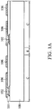
- FIGS. 1A to 1F are cross-sectional views of an exemplary method of forming a semiconductor package structure in accordance with some embodiments of the disclosure.
- a substrate 100 is provided.
- the substrate 100 may include a plurality of chip regions and a scribe line region that surrounds the plurality of chip regions and separates the adjacent chip regions from each other. To simplify the diagram, only two complete and adjacent chip regions C and a scribe line region S separating these chip regions C are depicted herein.
- the substrate 100 may be a silicon wafer so as to facilitate the wafer-level packaging process.
- the substrate 100 may be a silicon substrate or another semiconductor substrate.
- the chip regions C of the substrate 100 include integrated circuits (not shown) therein.
- an insulating layer 104 is formed on the substrate 100.
- the insulating layer 104 may serve as an inter-dielectric (ILD) layer, an inter-metal dielectric (IMD) layer, a passivation layer or a combination thereof. To simplify the diagram, only a flat layer is depicted herein.
- the insulating layer 104 is made of an inorganic material, such as silicon oxide (SiO x ), silicon nitride (SiN x ), silicon oxynitride (SiON), or a combination thereof, or another suitable insulating material.
- the insulating layer 104 includes one or more conductive pads 102 therein.
- the conductive pads 102 correspond to the chip regions C of the substrate 100 and are adjacent to the upper surface of the substrate 100.
- the conductive pad 122 may be formed of metal, such as copper, aluminum, or another suitable metal material.
- the ICs in the chip region C is electrically connected to the corresponding conductive pad 102.
- the aforementioned structure define a number of semiconductor dies/chips after the chip regions C are separated from each other by dicing the scribe line region S of the substrate 100.
- a conductive layer (not shown), such as a metal layer, is formed on the insulating layer 104 and passing through the insulating layer 104 to electrically couple to the exposed pads 102 in the chip regions C. Afterwards, the conductive layer is patterned to form a redistribution layer (RDL) structure 106 in each of the chip regions C, so that the RDL structure 106 is electrically coupled to the subsequent formed semiconductor die, as shown in FIG. 1A .
- RDL redistribution layer
- the chip regions C are separated from each other by dicing the scribe line region S of the substrate 100 to form semiconductor dies with the RDL structures 106 thereon.
- the formed semiconductor die may be a system on chip (SOC) integrated circuit die.
- the SOC integrated circuit die may include a logic die including a central processing unit (CPU), a graphics processing unit (GPU), a dynamic random access memory (DRAM) controller or any combination thereof.
- Each of semiconductor dies includes a substrate 100, at least one conductive pad 102 formed on the substrate 100, and an insulating layer 104 formed over the substrate 100 and having an opening to expose the conductive pad 102.
- the semiconductor die has a first surface 101a (e.g., an active surface of the semiconductor die), a second surface 101b (e.g., a non-active surface of the semiconductor die) opposite the first surface 101a, and a third surface 101c (e.g., a sidewall surface of the semiconductor die) adjoined between the first surface 101a and the second surface101b.
- a first surface 101a e.g., an active surface of the semiconductor die
- a second surface 101b e.g., a non-active surface of the semiconductor die
- a third surface 101c e.g., a sidewall surface of the semiconductor die
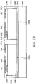
- a carrier substrate 200 with an adhesive layer 202 formed thereon is provided.
- the carrier substrate 200 may be made of silicon, glass, ceramic or the like, and may have a shape that is the same or similar to the semiconductor wafer, and therefore the carrier substrate 200 is sometimes referred to as a carrier wafer.
- the adhesive layer 202 may be made of a light-to-heat conversion (LTHC) material or another suitable material.
- LTHC light-to-heat conversion
- the second surface 101b of each semiconductor die that has an RDL structure 106 formed on the first surface 101a of the semiconductor die is mounted onto the carrier substrate 200 via the adhesive layer 202 using a pick-and-place process.
- a protective insulating layer 110 is formed to cover the first surface 101a and the third surface 101c of the semiconductor dies and to surround the RDL structures 106, so that each of the formed semiconductor dies with an RDL structure 106 thereon is encapsulated by the protective insulating layer 110.
- the protective insulating layer 110 protects the semiconductor dies from the environment, thereby preventing the semiconductor die in the subsequently formed semiconductor package structure from damage due to, for example, the stress, the chemicals and/or the moisture.
- the protective insulating layer 110 is made of an epoxy molding compound (EMC), an AjinomotoTM Build-up Film (ABF), or an acrylic-based material.
- the protective insulating layer 110 is made of an epoxy molding compound (EMC) and formed by a molding process.
- EMC epoxy molding compound
- the protective insulating layer 110 (such as in an epoxy or resin) may be applied while substantially liquid, and then may be cured through a chemical reaction.
- the protective insulating layer 110 may be an ultraviolet (UV) or thermally cured polymer applied as a gel or malleable solid capable of being formed around the semiconductor dies, and then may be cured through a UV or thermal curing process.
- the protective insulating layer 110 may be cured with a mold (not shown).
- the semiconductor dies with RDL structures 106 encapsulated by the protective insulating layer 110 are de-bonded from the carrier substrate 200, as shown in FIG. 1C .
- a de-bonding process is performed by exposing the adhesive layer 202 (shown in FIG. 1B ) using a laser or UV light when the adhesive layer 202 is made of an LTHC material.
- the LTHC material may be decomposed due to generated heat from the laser or UV light, and hence the carrier substrate 200 is removed from the structure including the semiconductor dies, the RDL structures 106, and the protective insulating layer 110.
- the second surface 101b of each semiconductor die is exposed from the protective insulating layer 110.
- the resulting structure is shown in FIG. 1C .
- a grinding process is performed on the top surface of the protective insulating layer 110 until the RDL structures 106 are exposed from the protective insulating layer 110, as shown in FIG. 1D .
- the top surface of the protective insulating layer 110 may be grinded by a chemical mechanical polishing (CMP) process or another suitable grinding process.
- CMP chemical mechanical polishing
- the protective insulating layer 110 and the RDL structures 106 are covered with a passivation layer 112, as shown in FIG. 1E .
- the passivation layer 112 is formed on the protective insulating layer 110 and the RDL structures 106 by a coating process or another suitable deposition process. Afterwards, the passivation layer 112 is patterned by lithography or a combination of lithograph and etching to form openings that expose the RDL structures 106.
- the passivation layer 112 is made of a material that is different from the material of the protective insulating layer 110.
- the passivation layer 112 is made of polyimide or polybenzoxazole (PBO).
- the passivation layer 112 is also divided into several portions, so that each of the semiconductor dies is covered by a respective portion of passivation layer 112. In some other embodiments, the passivation layer 112 is divided into several portions by the subsequent dicing process.
- conductive structures 120 respectively pass through the passivation layer 112 via those openings formed in the passivation layer 112, as shown in FIG. 1E .
- the conductive structures 120 fill into the openings formed in the passivation layer 112, so that each of the conductive structures 120 is electrically coupled to the respective exposed RDL structure 106 under the opening in the passivation layer 112.
- the conductive structure 120 includes an optional under-bump metallurgy (UBM) layer 122 and a solder bump 124 on the UBM layer 122.
- the conductive structure 120 includes a conductive bump structure such as a copper bump, a conductive pillar structure, a conductive wire structure, or a conductive paste structure.
- an optional protective insulating layer 130 is formed to cover the exposed second surfaces 101b of the semiconductor dies, as shown in FIG. 1F .
- the protective insulating layer 130 is sometimes referred to as a die backside film (DBF) that is made of a thermoset material, such as an epoxy resin material.
- the protective insulating layer 130 is made of a material that is the same as the material of the protective insulating layer 110.
- the protective insulating layer 130 is made of an epoxy molding compound (EMC), an AjinomotoTM Build-up Film (ABF), or an acrylic-based material.
- a singulation is carried out to saw through the formed structure shown in FIG. 1F .
- a dicing process may be performed on the formed structure shown in FIG. 1F .
- multiple separate semiconductor package structures are formed.
- FIG. 2A is a cross-sectional view of an exemplary semiconductor package structure in accordance with some embodiments.
- the semiconductor package structure 10a includes a semiconductor die that includes a substrate 100, at least one conductive pad 102 formed on the substrate 100, and an insulating layer 104 formed over the substrate 100 and having an opening to expose the conductive pad 102, as shown in FIG. 2A .
- the semiconductor die has a first surface 101a (e.g., an active surface of the semiconductor die), a second surface 101b (e.g., a non-active surface of the semiconductor die) opposite the first surface 101a, and a third surface 101c (e.g., a sidewall surface of the semiconductor die) adjoined between the first surface 101a and the second surface101b.
- a first surface 101a e.g., an active surface of the semiconductor die
- a second surface 101b e.g., a non-active surface of the semiconductor die
- a third surface 101c e.g., a sidewall surface of the semiconductor die
- the semiconductor package structure 10a further includes a protective insulating layer 110 that covers the first surface 101a and the third surface 101c of the semiconductor die, and a protective insulating layer 130 that covers the second surface 101b of the semiconductor die.
- the thickness of the portion of the protective insulating layer 110 covering the first surface 101a and the thickness of the of the portion of the protective insulating layer 110 covering the third surface 101c of the semiconductor die can be adjusted, so as to fine-tune the protection ability of the semiconductor package structure 10a.
- the protective insulating layer 110 and the protective insulating layer 130 are made of the same material or different materials.
- a material may include an epoxy molding compound (EMC), an AjinomotoTM Build-up Film (ABF), or an acrylic-based material.
- the protective insulating layer 110 is made of an epoxy molding compound (EMC), an AjinomotoTM Build-up Film (ABF), or an acrylic-based material
- the protective insulating layer 130 is made of a DBF material that includes a thermoset material, such as an epoxy resin material.
- the semiconductor package structure 10a further includes an RDL structure 106 electrically coupled to the semiconductor die via the conductive pad 102 and surrounded by the protective insulating layer 110 on the first surface 101a of the semiconductor die.
- the semiconductor package structure 10a further includes a passivation layer 112 covering the RDL structure 106 and a portion of the protective insulating layer 110 surrounding the RDL structure 106.
- the passivation layer 112 may be made of polyimide or polybenzoxazole (PBO).
- the semiconductor package structure 10a further includes at least one conductive structure 120 that includes an optional UBM layer 122 and a solder bump 124 and passes through the passivation layer 110, so as to be electrically coupled to the semiconductor die through the RDL structure 106.
- the semiconductor package structure 10a shown in FIG. 2A is a CSP structure.
- the CSP structure may include an SOC package.
- the semiconductor package structure 10a may be mounted on a base (not shown).
- the base may include a printed circuit board (PCB) and may be formed of polypropylene (PP).
- the base may include a package substrate.
- the semiconductor package structure 10a may be mounted on the base by a bonding process.
- the semiconductor package structure 10a may be mounted on the base by the bonding process and electrically coupled to the base using the conductive structures 120 as connectors.
- FIG. 2B is a cross-sectional view of an exemplary semiconductor package structure in accordance with some embodiments. Descriptions of elements of the embodiments hereinafter that are the same as or similar to those previously described with reference to FIG. 2A may be omitted for brevity.
- the semiconductor package structure 10b is similar to the semiconductor package structure 10a shown in FIG. 2A . Compared to the semiconductor package structure 10a, there is no protective insulating layer 130 formed in the package structure 10b, and hence the second surface 101b of the semiconductor die is exposed to the environment.
- the semiconductor package structure 10b is formed by a method that is similar to the method shown in FIGS. 1A to IF, except that the formation of the protective insulating layer 130, as shown in FIG. IF, is omitted. Namely, after the structure shown in FIG. 1E is formed, a singulation is carried out to saw through the formed structure shown in FIG. 1E .
- FIG. 3A is a cross-sectional view of an exemplary semiconductor package structure in accordance with some embodiments. Descriptions of elements of the embodiments hereinafter that are the same as or similar to those previously described with reference to FIG. 2A may be omitted for brevity.
- the semiconductor package structure 10c is similar to the semiconductor package structure 10a shown in FIG. 2A . Compared to the semiconductor package structure 10a, the semiconductor package structure 10c further includes a passivation layer 105 formed between the first surface 101a of the semiconductor die and the RDL structure 106 and covered by the protective insulating layer 110. In some embodiments, the material and the method used for the passivation layer 105 are the same as or similar to those used for the passivation layer 112.
- the passivation layer 105 is made of polyimide or polybenzoxazole (PBO).
- the semiconductor package structure 10c is formed by a method that is similar to the method shown in FIGS. 1A to 1F , except that an additional passivation layer 105 is formed prior to the formation of the RDL structure 106.
- an additional passivation layer 105 is formed prior to the formation of the RDL structure 106.
- Prior to the formation of the RDL structure 106 at least one opening is formed in the passivation layer 105, so that the passivation layer 105 exposes the conductive pad 102 and surrounds the opening formed in the insulating layer 104.
- FIG. 3B is a cross-sectional view of an exemplary semiconductor package structure in accordance with some embodiments. Descriptions of elements of the embodiments hereinafter that are the same as or similar to those previously described with reference to FIGS. 2A and 3A may be omitted for brevity.
- the semiconductor package structure 10d is similar to the semiconductor package structure 10c shown in FIG. 3A . Compared to the semiconductor package structure 10c, there is no protective insulating layer 130 formed in the package structure 10d, and hence the second surface 101b of the semiconductor die is exposed to the environment.
- the semiconductor package structure 10d is formed by a method that is similar to the method used for forming the semiconductor package structure 10c, except that the formation of the protective insulating layer 130 is omitted.
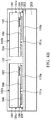
- FIGS. 4A to 4E are cross-sectional views of an exemplary method of forming a semiconductor package structure in accordance with some embodiments of the disclosure. Descriptions of elements of the embodiments hereinafter that are the same as or similar to those previously described with reference to FIGS. 1A to 1F may be omitted for brevity.
- a structure as shown in FIG. 1A is provided.
- a protective insulating layer 110a to cover the first surface 101a of each semiconductor die and surround each RDL structure 106, so that the top surfaces and sidewalls of the RDL structures 106 are covered or encapsulated by the protective insulating layer 110a.
- the protective insulating layer 110a is made of an epoxy molding compound (EMC), an AjinomotoTM Build-up Film (ABF), or an acrylic-based material. In some embodiments, the protective insulating layer 110a is formed by a coating process, a molding process, or another suitable process.
- EMC epoxy molding compound
- ABSF AjinomotoTM Build-up Film
- acrylic-based material acrylic-based material.
- the protective insulating layer 110a is formed by a coating process, a molding process, or another suitable process.
- the chip regions C are separated from each other by dicing the scribe line region S of the substrate 100 to form semiconductor dies with the RDL structures 106 thereon.
- the formed semiconductor die has a first surface 101a (e.g., an active surface of the semiconductor die), a second surface 101b (e.g., a non-active surface of the semiconductor die) opposite the first surface 101a, and a third surface 101c (e.g., a sidewall surface of the semiconductor die) adjoined between the first surface 101a and the second surface101b.
- the protective insulating layer 110a has a sidewall 109 that is substantially aligned with the third surface 101c of the semiconductor die.
- a carrier substrate 200 with an adhesive layer 202 formed thereon is provided.
- each of the formed semiconductor dies with an RDL structure 106 formed on the first surface 101a of the semiconductor die is mounted onto the carrier substrate 200 by attaching the top surface of the protective insulating layer 110a to the adhesive layer 202 using a pick-and-place process.
- the second surface 101b of each semiconductor die is opposite the carrier substrate 200.
- a protective insulating layer 110 is formed using a molding process to cover the second surface 101b and the third surface 101c of the semiconductor dies and surround the protective insulating layer 110a, so that the protective insulating layer 110 extends from the third surface 101c of each semiconductor die to the sidewall 109 of the respective protective insulating layer.
- each of the formed semiconductor dies with an RDL structure 106 thereon is encapsulated by a protective structure including the protective insulating layer 110a and the protective insulating layer 110.
- the protective structure protects the semiconductor dies from the environment, thereby preventing the semiconductor die in the subsequently formed semiconductor package structure from damage due to, for example, the stress, the chemicals and/or the moisture.
- the protective insulating layer 110 of the protective structure is formed by a molding process while the protective insulating layer 110a of the protective structure is formed by a coating process.
- the semiconductor dies with RDL structures 106 encapsulated by the protective structure are de-bonded from the carrier substrate 200 by a de-bonding process as shown in FIG. 1C .
- the resulting structure is shown in FIG. 4C .
- a grinding process is performed on the protective insulating layer 110a above the RDL structures 106 and a portion of the protective insulating layer 110 surrounding the protective insulating layer 110a until the RDL structures 106 are exposed from the protective insulating layer 110a, as shown in FIG. 4D .
- the protective insulating layer 110a and the protective insulating layer 110 may be grinded by a CMP process or another suitable grinding process.
- the protective insulating layer 110a and the RDL structures 106 are covered with a patterned passivation layer 112, as shown in FIG. 4E .
- the passivation layer 112 is made of a material that is different from the material of the protective insulating layer 110a and the material of the protective insulating layer 110.
- the passivation layer 112 is also divided into several portions, so that each of the semiconductor dies is covered by a respective portion of passivation layer 112. In some other embodiments, the passivation layer 112 is divided into several portions by the subsequent dicing process.
- conductive structures 120 including an optional UBM layer 122 and a solder bump 124 respectively pass through the passivation layer 112 via those openings, as shown in FIG. 4E .
- each of the conductive structures 120 is electrically coupled to the respective exposed RDL structure 106.
- a singulation e.g., a dicing process
- saw through the formed structure shown in FIG. 4E a singulation (e.g., a dicing process) is carried out to saw through the formed structure shown in FIG. 4E .
- a singulation e.g., a dicing process
- FIG. 5A is a cross-sectional view of an exemplary semiconductor package structure in accordance with some embodiments.
- the semiconductor package structure 20a includes a semiconductor die that includes a substrate 100, at least one conductive pad 102 formed on the substrate 100, and an insulating layer 104 formed over the substrate 100 and having an opening to expose the conductive pad 102, as shown in FIG. 5A .
- the semiconductor die has a first surface 101a (e.g., an active surface of the semiconductor die), a second surface 101b (e.g., a non-active surface of the semiconductor die) opposite the first surface 101a, and a third surface 101c (e.g., a sidewall surface of the semiconductor die) adjoined between the first surface 101a and the second surface101b.
- a first surface 101a e.g., an active surface of the semiconductor die
- a second surface 101b e.g., a non-active surface of the semiconductor die
- a third surface 101c e.g., a sidewall surface of the semiconductor die
- the semiconductor package structure 20a further includes a protective insulating layer 110a that covers the first surface 101a of the semiconductor die, and a protective insulating layer 110 that covers the second surface 101b and the third surface 101c of the semiconductor die and that surrounds the protective insulating layer 110a.
- the protective insulating layer 110a has a sidewall 109 that is substantially aligned with the third surface 101c of the semiconductor die.
- the protective insulating layer 110 extends from the third surface 101c of the semiconductor die to the sidewall 109 of the protective insulating layer 110a.
- the thickness of the protective insulating layer 110a covering the first surface 101a and the thickness of the protective insulating layer 110 covering the second surface 101b and the third surface 101c of the semiconductor die can be adjusted, so as to fine-tune the protection ability of the semiconductor package structure 20a.
- the protective insulating layer 110a and the protective insulating layer 110 are made of the same material or different materials.
- a material may include an epoxy molding compound (EMC), an AjinomotoTM Build-up Film (ABF), or an acrylic-based material.
- the semiconductor package structure 20a further includes an RDL structure 106 electrically coupled to the semiconductor die via the conductive pad 102 and surrounded by the protective insulating layer 110a.
- the semiconductor package structure 20a further includes a passivation layer 112 covering the RDL structure 106 and a portion of the protective insulating layer 110a surrounding the RDL structure 106.
- the passivation layer 112 is made of for example, polyimide or polybenzoxazole (PBO).
- the semiconductor package structure 20a further includes at least one conductive structure 120 that includes an optional UBM layer 122 and a solder bump 124 and passes through the passivation layer 110, so as to be electrically coupled to the semiconductor die through the RDL structure 106.
- the semiconductor package structure 20a shown in FIG. 5A is a CSP structure.
- the CSP structure may include an SOC package.
- the semiconductor package structure 20a may be mounted on a base (not shown).
- the base may include a printed circuit board (PCB) and may be formed of polypropylene (PP).
- the base may include a package substrate. Similar to the semiconductor package structure 10a, the semiconductor package structure 20a may be mounted on the base by a bonding process and electrically coupled to the base using the conductive structures 120 as connectors.
- FIG. 5B is a cross-sectional view of an exemplary semiconductor package structure in accordance with some embodiments. Descriptions of elements of the embodiments hereinafter that are the same as or similar to those previously described with reference to FIG. 5A may be omitted for brevity.
- the semiconductor package structure 20b is similar to the semiconductor package structure 20a shown in FIG. 5A . Compared to the semiconductor package structure 20a, the semiconductor package structure 20b further includes a passivation layer 105 formed between the first surface 101a of the semiconductor die and the RDL structure 106 and covered by the protective insulating layer 110a.
- the material and the method used for the passivation layer 105 are the same as or similar to those used for the passivation layer 112 and different from those used for the protective insulating layer 110a and those used for the protective insulating layer 110.
- the semiconductor package structure 20b is formed by a method that is similar to the method shown in FIGS. 4A to 4E , except that an additional passivation layer 105 is formed prior to the formation of the RDL structure 106. Prior to the formation of the RDL structure 106, at least one opening is formed in the passivation layer 105, so that the passivation layer 105 exposes the conductive pad 102 and surrounds the opening formed in the insulating layer 104.
- FIGS. 6A to 6E are cross-sectional views of an exemplary method of forming a semiconductor package structure in accordance with some embodiments of the disclosure. Descriptions of elements of the embodiments hereinafter that are the same as or similar to those previously described with reference to FIGS. 1A to 1F or 4A to 4E may be omitted for brevity.
- FIG. 6A a structure as shown in FIG. 1A is provided. Afterwards, the chip regions C are separated from each other by dicing the scribe line region S of the substrate 100 to form semiconductor dies with the RDL structures 106 thereon.
- the formed semiconductor die has a first surface 101a (e.g., an active surface of the semiconductor die), a second surface 101b (e.g., a non-active surface of the semiconductor die) opposite the first surface 101a, and a third surface 101c (e.g., a sidewall surface of the semiconductor die) adjoined between the first surface 101a and the second surface101b.
- a first surface 101a e.g., an active surface of the semiconductor die
- a second surface 101b e.g., a non-active surface of the semiconductor die
- a third surface 101c e.g., a sidewall surface of the semiconductor die
- a carrier substrate 200 with an adhesive layer 202 formed thereon is provided.
- each of the formed semiconductor dies with an RDL structure 106 formed on the first surface 101a of the semiconductor die is mounted onto the carrier substrate 200 by attaching the top surface and sidewall surface of the RDL structure 106 to the adhesive layer 202 using a pick-and-place process.
- the second surface 101b of each semiconductor die is opposite the carrier substrate 200.
- a protective insulating layer 110 is formed using a molding process to cover the second surface 101b and the third surface 101c of the semiconductor dies and surround the protective insulating layer 110a, so that the protective insulating layer 110 extends from the third surface 101c of each semiconductor die to the sidewall 109 of the respective protective insulating layer.
- the semiconductor dies with RDL structures 106 are de-bonded from the carrier substrate 200 by a de-bonding process (as shown in FIG. 1C ).
- the resulting structure is shown in FIG. 6B .
- a protective insulating layer 110a is formed by a coating process to cover the first surface 101a of each semiconductor die and surround each RDL structure 106, as shown in FIG. 6C .
- the protective insulating layer 110a is formed by a molding process or another suitable process.
- each of the formed semiconductor dies with an RDL structure 106 thereon is encapsulated.
- the protective structure protects the semiconductor dies from the environment, thereby preventing the semiconductor die in the subsequently formed semiconductor package structure from damage due to, for example, the stress, the chemicals and/or the moisture.
- a grinding process is performed on the protective insulating layer 110a above the RDL structures 106 until the RDL structures 106 are exposed from the protective insulating layer 110a, as shown in FIG. 6D .
- the protective insulating layer 110a may be grinded by a CMP process or another suitable grinding process.
- the protective insulating layer 110a and the RDL structures 106 are covered with a patterned passivation layer 112, as shown in FIG. 6E .
- the passivation layer 112 is made of a material that is different from the material of the protective insulating layer 110a and the material of the protective insulating layer 110.
- the passivation layer 112 is also divided into several portions, so that each of the semiconductor dies is covered by a respective portion of passivation layer 112. In some other embodiments, the passivation layer 112 is divided into several portions by the subsequent dicing process.
- conductive structures 120 including an optional UBM layer 122 and a solder bump 124 respectively pass through the passivation layer 112 via those openings, as shown in FIG. 6E .
- each of the conductive structures 120 is electrically coupled to the respective exposed RDL structure 106.
- a singulation e.g., a dicing process
- the protective insulating layer 110a has a sidewall and a portion of the protective insulating layer covering the third surface 101c of the semiconductor die has a sidewall, and those sidewalls are substantially aligned with each other.
- FIG. 7A is a cross-sectional view of an exemplary semiconductor package structure in accordance with some embodiments.
- the semiconductor package structure 30a includes a semiconductor die that includes a substrate 100, at least one conductive pad 102 formed on the substrate 100, and an insulating layer 104 formed over the substrate 100 and having an opening to expose the conductive pad 102, as shown in FIG. 7A .
- the semiconductor die has a first surface 101a (e.g., an active surface of the semiconductor die), a second surface 101b (e.g., a non-active surface of the semiconductor die) opposite the first surface 101a, and a third surface 101c (e.g., a sidewall surface of the semiconductor die) adjoined between the first surface 101a and the second surface101b.
- a first surface 101a e.g., an active surface of the semiconductor die
- a second surface 101b e.g., a non-active surface of the semiconductor die
- a third surface 101c e.g., a sidewall surface of the semiconductor die
- the semiconductor package structure 30a further includes a protective insulating layer 110a that covers the first surface 101a of the semiconductor die, and a protective insulating layer 110 that covers the second surface 101b and the third surface 101c of the semiconductor die and that surrounds the protective insulating layer 110a.
- the protective insulating layer 110a has a sidewall 109 and a portion of the protective insulating layer 110a covering the third surface 101c of the semiconductor die has a sidewall 113.
- the sidewall 109 is substantially aligned with the sidewall 113.
- the portion of the protective insulating layer 110 covering the third surface 101c of the semiconductor die is capped by the protective insulating layer 110a.
- the thickness of the protective insulating layer 110a covering the first surface 101a and the thickness of the protective insulating layer 110 covering the second surface 101b and the third surface 101c of the semiconductor die can be adjusted, so as to fine-tune the protection ability of the semiconductor package structure 30a.
- the protective insulating layer 110a and the protective insulating layer 110 are made of the same material or different materials.
- a material may include an epoxy molding compound (EMC), an AjinomotoTM Build-up Film (ABF), or an acrylic-based material.
- the semiconductor package structure 30a further includes an RDL structure 106 electrically coupled to the semiconductor die via the conductive pad 102 and surrounded by the protective insulating layer 110a.
- the semiconductor package structure 30a further includes a passivation layer 112 covering the RDL structure 106 and a portion of the protective insulating layer 110a surrounding the RDL structure 106.
- the passivation layer 112 is made of for example, polyimide or polybenzoxazole (PBO).
- the semiconductor package structure 30a further includes at least one conductive structure 120 that includes an optional UBM layer 122 and a solder bump 124 and passes through the passivation layer 110, so as to be electrically coupled to the semiconductor die through the RDL structure 106.
- the semiconductor package structure 30a shown in FIG. 7A is a CSP structure.
- the CSP structure may include an SOC package.
- the semiconductor package structure 30a may be mounted on a base (not shown).
- the base may include a printed circuit board (PCB) and may be formed of polypropylene (PP).
- the base may include a package substrate. Similar to the semiconductor package structure 10a or 20a, the semiconductor package structure 30a may be mounted on the base by a bonding process and electrically coupled to the base using the conductive structures 120 as connectors.
- FIG. 7B is a cross-sectional view of an exemplary semiconductor package structure in accordance with some embodiments. Descriptions of elements of the embodiments hereinafter that are the same as or similar to those previously described with reference to FIG. 7A may be omitted for brevity.
- the semiconductor package structure 30b is similar to the semiconductor package structure 30a shown in FIG. 7A . Compared to the semiconductor package structure 30a, the semiconductor package structure 30b further includes a passivation layer 105 formed between the first surface 101a of the semiconductor die and the RDL structure 106 and covered by the protective insulating layer 110a.
- the material and the method used for the passivation layer 105 are the same as or similar to those used for the passivation layer 112 and from those used for the protective insulating layer 110a and those used for the protective insulating layer 110.
- the semiconductor package structure 30b is formed by a method that is similar to the method shown in FIGS. 6A to 6E , except that an additional passivation layer 105 is formed prior to the formation of the RDL structure 106. Prior to the formation of the RDL structure 106, at least one opening is formed in the passivation layer 105, so that the passivation layer 105 exposes the conductive pad 102 and surrounds the opening formed in the insulating layer 104.
- the semiconductor package structure is designed to fabricate a protective structure in the semiconductor package structure to cover or encapsulate the semiconductor die in the semiconductor package structure.
- the protective structure includes one or more protective insulating layers to protect the semiconductor die from the environment, thereby preventing the semiconductor die in the semiconductor package structure from damage due to, for example, the stress, the chemicals and/or the moisture.
- the reliability of the semiconductor package structure can be maintained during the subsequent thermal process (such as a surface mount technology (SMT) process or a bonding process).
- the RDL structure formed on the semiconductor die is also protected by the protective structure, so as to keep its electrical and thermal performance.
- the semiconductor die in the semiconductor package structure can be prevented from chipping when the CSP structure is placed in a test socket for performing a test process.
Landscapes
- Engineering & Computer Science (AREA)
- Microelectronics & Electronic Packaging (AREA)
- Structures Or Materials For Encapsulating Or Coating Semiconductor Devices Or Solid State Devices (AREA)
- Internal Circuitry In Semiconductor Integrated Circuit Devices (AREA)
Abstract
Description
- This application claims the benefit of
U.S. Provisional Application No. 62/731,128 filed on September 14, 2018 - The present invention relates to semiconductor package technology, and in particular to a wafer level chip scale package (WLCSP) structure.
- Integrated circuit (IC) devices are fabricated in a semiconductor wafer and divided into individual chips. Afterwards, those chips are assembled in package form to be used in electronic products. The package provides a structure to support the chip and protect the chip from the environment. The package also provides electrical connections to and from the chip.
- In recent years, as electronic products have been become increasingly multifunctional and have been scaled down in size, there is a desire for manufacturers of semiconductor devices to make more devices formed on a single semiconductor wafer, so that the electronic products that include these devices can be made more compact. This results in many new challenges to the structural and electrical design of the package.
- Accordingly, a chip scale package (CSP) technology has been developed to satisfy the industry's demands (e.g., the smaller chip size and form factor). Moreover, a wafer level package (WLP) technology also has been introduced for cost-effective fabrication of packages. Such a technology is referred to as wafer-level chip scale package (WLCSP).
- However, in the use of the WLCSP process, the surface of each chip in the respective package is exposed to the environment after the packages are separated from the package wafer. As a result, damage to the chip may occur, thereby reducing the reliability of the semiconductor packages. Thus, a novel semiconductor package structure and the fabrication method thereof are desirable.
- Semiconductor package structures and methods for forming the same are provided. An exemplary embodiment of a semiconductor package structure includes a semiconductor die having a first surface, a second surface opposite the first surface, and a third surface adjoined between the first surface and the second surface. A first protective insulating layer covers the first surface and the third surface of the semiconductor die, A redistribution layer (RDL) structure is electrically coupled to the semiconductor die and surrounded by the first protective insulating layer on the first surface of the semiconductor die. A first passivation layer covers the first protective insulating layer and the RDL structure. At least one conductive structure passes through the first passivation layer and is electrically coupled to the RDL structure. The following features may be provided individually or in any combination thereof.
- In one or more embodiments, the semiconductor package structure may further comprise a second protective insulating layer covering the second surface of the semiconductor die. The first protective insulating layer and the second protective insulating layer respectively may comprise an epoxy molding compound (EMC), an Ajinomoto™ Build-up Film (ABF), or an acrylic-based material. Further, the first protective insulating layer and the second protective insulating layer may comprise a different or the same material. The semiconductor package structure further may comprise a second passivation layer between the first surface of the semiconductor die and the RDL structure and covered by the first protective insulating layer. The first passivation layer may comprise a material that is the same as a material of the second passivation layer and different from a material of the first protective insulating layer. The first passivation layer and the second passivation layer may e.g. comprise polyimide or polybenzoxazole (PBO). The semiconductor package structure may further comprise: a second protective insulating layer covering the second surface of the semiconductor die; and a second passivation layer between the first surface of the semiconductor die and the RDL structure and covered by the first protective insulating layer. The conductive structure may comprise an under-bump metallurgy (UBM) layer and a solder bump on the UBM layer.
- Another exemplary embodiment of a semiconductor package structure includes a semiconductor die having a first surface, a second surface opposite the first surface, and a third surface adjoined between the first surface and the second surface. A first protective insulating layer covers the first surface of the semiconductor die. An RDL structure is electrically coupled to the semiconductor die and surrounded by the first protective insulating layer. A second protective insulating layer covers the second surface and the third surface of the semiconductor die. A first passivation layer covers the first protective insulating layer and the RDL structure. At least one conductive structure passes through the first passivation layer and is electrically coupled to the RDL structure. The following features may be provided individually or in any combination thereof.
- In one or more embodiments, the first protective insulating layer and the second protective insulating layer respectively may comprise an epoxy molding compound (EMC), an Ajinomoto™ Build-up Film (ABF), or an acrylic-based material. The semiconductor package structure may comprise a second passivation layer between the first surface of the semiconductor die and the RDL structure and covered by the first protective insulating layer. The first passivation layer may comprises a material that is the same as a material of the second passivation layer and different from a material of the first protective insulating layer and a material of the second protective insulating layer. The first protective insulating layer may have a sidewall that is substantially aligned with the third surface of the semiconductor die. Or, the first protective insulating layer may have a sidewall and the second protective insulating layer extends from the third surface of the semiconductor die to the sidewall of the first protective insulating layer. Or, the first protective insulating layer may have a first sidewall and a portion of the second protective insulating layer covering the third surface of the semiconductor die has a second sidewall, and wherein the first sidewall is substantially aligned with the second sidewall. Further, a portion of the second protective insulating layer covering the third surface of the semiconductor die may be capped by the first protective insulating layer. The conductive structure may comprise an under-bump metallurgy (UBM) layer and a solder bump on the UBM layer.
- An exemplary embodiment of a method of forming a semiconductor package structure including providing a semiconductor die. The semiconductor die has a first surface, a second surface opposite the first surface, and a third surface adjoined between the first surface and the second surface. An RDL structure is formed on the first surface of the semiconductor die. The RDL structure is electrically coupled to the semiconductor die. A first protective insulating layer is formed to cover the first surface and the third surface of the semiconductor die and to surround the RDL structure. The first protective insulating layer and the RDL structure are covered with a first passivation layer. At least one conductive structure passing through the first passivation layer is formed to be electrically coupled to the RDL structure. The following features may be provided individually or in any combination thereof.
- In one or more embodiments, the method may further comprise forming a second protective insulating layer to cover the second surface of the semiconductor die. The first protective insulating layer and the second protective insulating layer respectively may comprise an epoxy molding compound (EMC), an Ajinomoto™ Build-up Film (ABF), or an acrylic-based material. The first protective insulating layer may be formed by a molding process, The method may further comprise forming a second passivation layer on the first surface of the semiconductor die before forming the RDL structure. The first passivation layer may comprise a material that is the same as a material of the second passivation layer and different from a material of the first protective insulating layer. The first passivation layer and the second passivation layer may comprise polyimide or polybenzoxazole (PBO). The method may further comprise: forming a second passivation layer on the first surface of the semiconductor die before forming the RDL structure; and forming a second protective insulating layer to cover the second surface of the semiconductor die after forming the conductive structure. The conductive structure may comprise an under-bump metallurgy (UBM) layer and a solder bump on the UBM layer.
- Another exemplary embodiment of a method of forming a semiconductor package structure including providing a semiconductor die. The semiconductor die has a first surface, a second surface opposite the first surface, and a third surface adjoined between the first surface and the second surface. An RDL structure is formed on the first surface of the semiconductor die. The RDL structure is electrically coupled to the semiconductor die. A first protective insulating layer is formed to cover the first surface of the semiconductor die and to surround the RDL structure. A second protective insulating layer is formed to cover the second surface and the third surface of the semiconductor die. A first passivation layer is formed to cover the first protective insulating layer and the RDL structure. At least one conductive structure passing through the first passivation layer is formed to be electrically coupled to the RDL structure. The following features may be provided individually or in any combination thereof.
- In one or more embodiments, the first protective insulating layer and the second protective insulating layer respectively may comprise an epoxy molding compound (EMC), an Ajinomoto™ Build-up Film (ABF), or an acrylic-based material. The method may further comprise forming a second passivation layer on the first surface of the semiconductor die before forming the RDL structure. The first passivation layer may comprises a material that is the same as a material of the second passivation layer and different from a material of the first protective insulating layer and a material of the second protective insulating layer. The first protective insulating layer may be formed by a coating process before forming the second protective insulating layer using a molding process. The first protective insulating layer may be formed by a coating process after forming the second protective insulating layer using a molding process. The first protective insulating layer may have a sidewall that is substantially aligned with the third surface of the semiconductor die, and wherein the second protective insulating layer extends from the third surface of the semiconductor die to the sidewall of the first protective insulating layer. OR, the first protective insulating layer may have a first sidewall and a portion of the second protective insulating layer covering the third surface of the semiconductor die has a second sidewall, and wherein the first sidewall is substantially aligned with the second sidewall. A portion of the second protective insulating layer covering the third surface of the semiconductor die may be capped by the first protective insulating layer. The conductive structure may comprise an under-bump metallurgy (UBM) layer and a solder bump on the UBM layer.
- A detailed description is given in the following embodiments with reference to the accompanying drawings.
- The present invention can be more fully understood by reading the subsequent detailed description and examples with references made to the accompanying drawings, wherein:
-
FIGS. 1A to 1F are cross-sectional views of an exemplary method of forming a semiconductor package structure in accordance with some embodiments. -
FIG. 2A is a cross-sectional view of an exemplary semiconductor package structure in accordance with some embodiments. -
FIG. 2B is a cross-sectional view of an exemplary semiconductor package structure in accordance with some embodiments. -
FIG. 3A is a cross-sectional view of an exemplary semiconductor package structure in accordance with some embodiments. -
FIG. 3B is a cross-sectional view of an exemplary semiconductor package structure in accordance with some embodiments. -
FIGS. 4A to 4E are cross-sectional views of an exemplary method of forming a semiconductor package structure in accordance with some embodiments. -
FIG. 5A is a cross-sectional view of an exemplary semiconductor package structure in accordance with some embodiments. -
FIG. 5B is a cross-sectional view of an exemplary semiconductor package structure in accordance with some embodiments. -
FIGS. 6A to 6E are cross-sectional views of an exemplary method of forming a semiconductor package structure in accordance with some embodiments. -
FIG. 7A is a cross-sectional view of an exemplary semiconductor package structure in accordance with some embodiments. -
FIG. 7B is a cross-sectional view of an exemplary semiconductor package structure in accordance with some embodiments. - The following description is of the best-contemplated mode of carrying out the invention. This description is made for the purpose of illustrating the general principles of the invention and should not be taken in a limiting sense. The scope of the invention is determined by reference to the appended claims.
- The present invention will be described with respect to particular embodiments and with reference to certain drawings, but the invention is not limited thereto and is only limited by the claims. The drawings described are only schematic and are non-limiting. In the drawings, the size of some of the elements may be exaggerated for illustrative purposes and not drawn to scale. The dimensions and the relative dimensions do not correspond to actual dimensions in the practice of the invention.
-
FIGS. 1A to 1F are cross-sectional views of an exemplary method of forming a semiconductor package structure in accordance with some embodiments of the disclosure. As shown inFIG. 1A , asubstrate 100 is provided. In some embodiments, thesubstrate 100 may include a plurality of chip regions and a scribe line region that surrounds the plurality of chip regions and separates the adjacent chip regions from each other. To simplify the diagram, only two complete and adjacent chip regions C and a scribe line region S separating these chip regions C are depicted herein. Thesubstrate 100 may be a silicon wafer so as to facilitate the wafer-level packaging process. For example, thesubstrate 100 may be a silicon substrate or another semiconductor substrate. - In some embodiments, the chip regions C of the
substrate 100 include integrated circuits (not shown) therein. In some embodiments, an insulatinglayer 104 is formed on thesubstrate 100. The insulatinglayer 104 may serve as an inter-dielectric (ILD) layer, an inter-metal dielectric (IMD) layer, a passivation layer or a combination thereof. To simplify the diagram, only a flat layer is depicted herein. In some embodiments, the insulatinglayer 104 is made of an inorganic material, such as silicon oxide (SiOx), silicon nitride (SiNx), silicon oxynitride (SiON), or a combination thereof, or another suitable insulating material. - Moreover, the insulating
layer 104 includes one or moreconductive pads 102 therein. Theconductive pads 102 correspond to the chip regions C of thesubstrate 100 and are adjacent to the upper surface of thesubstrate 100. Theconductive pad 122 may be formed of metal, such as copper, aluminum, or another suitable metal material. To simplify the diagram, only oneconductive pad 102 formed on thesubstrate 100 in each chip region C and exposed from the insulatinglayer 104 is depicted herein as an example. In some embodiments, the ICs in the chip region C is electrically connected to the correspondingconductive pad 102. The aforementioned structure define a number of semiconductor dies/chips after the chip regions C are separated from each other by dicing the scribe line region S of thesubstrate 100. - In some embodiments, a conductive layer (not shown), such as a metal layer, is formed on the insulating
layer 104 and passing through the insulatinglayer 104 to electrically couple to the exposedpads 102 in the chip regions C. Afterwards, the conductive layer is patterned to form a redistribution layer (RDL)structure 106 in each of the chip regions C, so that theRDL structure 106 is electrically coupled to the subsequent formed semiconductor die, as shown inFIG. 1A . - As shown in
FIG. 1B , in some embodiments, the chip regions C are separated from each other by dicing the scribe line region S of thesubstrate 100 to form semiconductor dies with theRDL structures 106 thereon. The formed semiconductor die may be a system on chip (SOC) integrated circuit die. The SOC integrated circuit die, for example, may include a logic die including a central processing unit (CPU), a graphics processing unit (GPU), a dynamic random access memory (DRAM) controller or any combination thereof. Each of semiconductor dies includes asubstrate 100, at least oneconductive pad 102 formed on thesubstrate 100, and an insulatinglayer 104 formed over thesubstrate 100 and having an opening to expose theconductive pad 102. Moreover, the semiconductor die has afirst surface 101a (e.g., an active surface of the semiconductor die), asecond surface 101b (e.g., a non-active surface of the semiconductor die) opposite thefirst surface 101a, and athird surface 101c (e.g., a sidewall surface of the semiconductor die) adjoined between thefirst surface 101a and the second surface101b. - As shown in
FIG. 1B , in some embodiments, acarrier substrate 200 with anadhesive layer 202 formed thereon is provided. Thecarrier substrate 200 may be made of silicon, glass, ceramic or the like, and may have a shape that is the same or similar to the semiconductor wafer, and therefore thecarrier substrate 200 is sometimes referred to as a carrier wafer. Theadhesive layer 202 may be made of a light-to-heat conversion (LTHC) material or another suitable material. Afterwards, in some embodiments, thesecond surface 101b of each semiconductor die that has anRDL structure 106 formed on thefirst surface 101a of the semiconductor die is mounted onto thecarrier substrate 200 via theadhesive layer 202 using a pick-and-place process. - Next, in some embodiments, a protective
insulating layer 110 is formed to cover thefirst surface 101a and thethird surface 101c of the semiconductor dies and to surround theRDL structures 106, so that each of the formed semiconductor dies with anRDL structure 106 thereon is encapsulated by the protective insulatinglayer 110. In some embodiments, the protective insulatinglayer 110 protects the semiconductor dies from the environment, thereby preventing the semiconductor die in the subsequently formed semiconductor package structure from damage due to, for example, the stress, the chemicals and/or the moisture. - In some embodiments, the protective insulating
layer 110 is made of an epoxy molding compound (EMC), an Ajinomoto™ Build-up Film (ABF), or an acrylic-based material. In some embodiments, the protective insulatinglayer 110 is made of an epoxy molding compound (EMC) and formed by a molding process. For example, the protective insulating layer 110 (such as in an epoxy or resin) may be applied while substantially liquid, and then may be cured through a chemical reaction. The protectiveinsulating layer 110 may be an ultraviolet (UV) or thermally cured polymer applied as a gel or malleable solid capable of being formed around the semiconductor dies, and then may be cured through a UV or thermal curing process. The protectiveinsulating layer 110 may be cured with a mold (not shown). - After the protective insulating
layer 110 is formed, the semiconductor dies withRDL structures 106 encapsulated by the protective insulatinglayer 110 are de-bonded from thecarrier substrate 200, as shown inFIG. 1C . In some embodiments, a de-bonding process is performed by exposing the adhesive layer 202 (shown inFIG. 1B ) using a laser or UV light when theadhesive layer 202 is made of an LTHC material. The LTHC material may be decomposed due to generated heat from the laser or UV light, and hence thecarrier substrate 200 is removed from the structure including the semiconductor dies, theRDL structures 106, and the protective insulatinglayer 110. As a result, thesecond surface 101b of each semiconductor die is exposed from the protective insulatinglayer 110. The resulting structure is shown inFIG. 1C . - In some embodiments, after the
carrier substrate 200 is removed by the de-bonding process, a grinding process is performed on the top surface of the protective insulatinglayer 110 until theRDL structures 106 are exposed from the protective insulatinglayer 110, as shown inFIG. 1D . For example, the top surface of the protective insulatinglayer 110 may be grinded by a chemical mechanical polishing (CMP) process or another suitable grinding process. - Afterwards, the protective insulating
layer 110 and theRDL structures 106 are covered with apassivation layer 112, as shown inFIG. 1E . In some embodiments, thepassivation layer 112 is formed on the protective insulatinglayer 110 and theRDL structures 106 by a coating process or another suitable deposition process. Afterwards, thepassivation layer 112 is patterned by lithography or a combination of lithograph and etching to form openings that expose theRDL structures 106. In some embodiments, thepassivation layer 112 is made of a material that is different from the material of the protective insulatinglayer 110. In some embodiments, thepassivation layer 112 is made of polyimide or polybenzoxazole (PBO). - In some embodiments, during patterning the
passivation layer 112, thepassivation layer 112 is also divided into several portions, so that each of the semiconductor dies is covered by a respective portion ofpassivation layer 112. In some other embodiments, thepassivation layer 112 is divided into several portions by the subsequent dicing process. - After openings are formed in the
passivation layer 112,conductive structures 120 respectively pass through thepassivation layer 112 via those openings formed in thepassivation layer 112, as shown inFIG. 1E . In some embodiments, theconductive structures 120 fill into the openings formed in thepassivation layer 112, so that each of theconductive structures 120 is electrically coupled to the respective exposedRDL structure 106 under the opening in thepassivation layer 112. - In some embodiments, the
conductive structure 120 includes an optional under-bump metallurgy (UBM)layer 122 and asolder bump 124 on theUBM layer 122. In some other embodiments, theconductive structure 120 includes a conductive bump structure such as a copper bump, a conductive pillar structure, a conductive wire structure, or a conductive paste structure. - After the
conductive structures 120 are formed, an optional protectiveinsulating layer 130 is formed to cover the exposedsecond surfaces 101b of the semiconductor dies, as shown inFIG. 1F . The protectiveinsulating layer 130 is sometimes referred to as a die backside film (DBF) that is made of a thermoset material, such as an epoxy resin material. In some other embodiments, the protective insulatinglayer 130 is made of a material that is the same as the material of the protective insulatinglayer 110. For example, the protective insulatinglayer 130 is made of an epoxy molding compound (EMC), an Ajinomoto™ Build-up Film (ABF), or an acrylic-based material. - In some embodiments, after the protective insulating
layer 130 is formed, a singulation is carried out to saw through the formed structure shown inFIG. 1F . For example, a dicing process may be performed on the formed structure shown inFIG. 1F . As a result, multiple separate semiconductor package structures are formed. -
FIG. 2A is a cross-sectional view of an exemplary semiconductor package structure in accordance with some embodiments. InFIG. 2A , one of thesemiconductor package structures 10a that is formed by dicing the formed structure shown inFIG. 1F is shown. Descriptions of elements of the embodiments hereinafter that are the same as or similar to those previously described with reference toFIGS. 1A to 1F may be omitted for brevity. In some embodiments, thesemiconductor package structure 10a includes a semiconductor die that includes asubstrate 100, at least oneconductive pad 102 formed on thesubstrate 100, and an insulatinglayer 104 formed over thesubstrate 100 and having an opening to expose theconductive pad 102, as shown inFIG. 2A . The semiconductor die has afirst surface 101a (e.g., an active surface of the semiconductor die), asecond surface 101b (e.g., a non-active surface of the semiconductor die) opposite thefirst surface 101a, and athird surface 101c (e.g., a sidewall surface of the semiconductor die) adjoined between thefirst surface 101a and the second surface101b. - In some embodiments, the
semiconductor package structure 10a further includes a protectiveinsulating layer 110 that covers thefirst surface 101a and thethird surface 101c of the semiconductor die, and a protectiveinsulating layer 130 that covers thesecond surface 101b of the semiconductor die. The thickness of the portion of the protective insulatinglayer 110 covering thefirst surface 101a and the thickness of the of the portion of the protective insulatinglayer 110 covering thethird surface 101c of the semiconductor die can be adjusted, so as to fine-tune the protection ability of thesemiconductor package structure 10a. - In some embodiments, the protective insulating
layer 110 and the protective insulatinglayer 130 are made of the same material or different materials. For example, such a material may include an epoxy molding compound (EMC), an Ajinomoto™ Build-up Film (ABF), or an acrylic-based material. Alternatively, the protective insulatinglayer 110 is made of an epoxy molding compound (EMC), an Ajinomoto™ Build-up Film (ABF), or an acrylic-based material, and the protective insulatinglayer 130 is made of a DBF material that includes a thermoset material, such as an epoxy resin material. - In some embodiments, the
semiconductor package structure 10a further includes anRDL structure 106 electrically coupled to the semiconductor die via theconductive pad 102 and surrounded by the protective insulatinglayer 110 on thefirst surface 101a of the semiconductor die. - In some embodiments, the
semiconductor package structure 10a further includes apassivation layer 112 covering theRDL structure 106 and a portion of the protective insulatinglayer 110 surrounding theRDL structure 106. Thepassivation layer 112 may be made of polyimide or polybenzoxazole (PBO). - In some embodiments, the
semiconductor package structure 10a further includes at least oneconductive structure 120 that includes anoptional UBM layer 122 and asolder bump 124 and passes through thepassivation layer 110, so as to be electrically coupled to the semiconductor die through theRDL structure 106. - In some embodiments, the
semiconductor package structure 10a shown inFIG. 2A is a CSP structure. The CSP structure may include an SOC package. Moreover, thesemiconductor package structure 10a may be mounted on a base (not shown). The base may include a printed circuit board (PCB) and may be formed of polypropylene (PP). Alternatively, the base may include a package substrate. Thesemiconductor package structure 10a may be mounted on the base by a bonding process. For example, thesemiconductor package structure 10a may be mounted on the base by the bonding process and electrically coupled to the base using theconductive structures 120 as connectors. -
FIG. 2B is a cross-sectional view of an exemplary semiconductor package structure in accordance with some embodiments. Descriptions of elements of the embodiments hereinafter that are the same as or similar to those previously described with reference toFIG. 2A may be omitted for brevity. In some embodiments, thesemiconductor package structure 10b is similar to thesemiconductor package structure 10a shown inFIG. 2A . Compared to thesemiconductor package structure 10a, there is no protective insulatinglayer 130 formed in thepackage structure 10b, and hence thesecond surface 101b of the semiconductor die is exposed to the environment. In some embodiments, thesemiconductor package structure 10b is formed by a method that is similar to the method shown inFIGS. 1A to IF, except that the formation of the protective insulatinglayer 130, as shown in FIG. IF, is omitted. Namely, after the structure shown inFIG. 1E is formed, a singulation is carried out to saw through the formed structure shown inFIG. 1E . -
FIG. 3A is a cross-sectional view of an exemplary semiconductor package structure in accordance with some embodiments. Descriptions of elements of the embodiments hereinafter that are the same as or similar to those previously described with reference toFIG. 2A may be omitted for brevity. In some embodiments, thesemiconductor package structure 10c is similar to thesemiconductor package structure 10a shown inFIG. 2A . Compared to thesemiconductor package structure 10a, thesemiconductor package structure 10c further includes apassivation layer 105 formed between thefirst surface 101a of the semiconductor die and theRDL structure 106 and covered by the protective insulatinglayer 110. In some embodiments, the material and the method used for thepassivation layer 105 are the same as or similar to those used for thepassivation layer 112. For example, thepassivation layer 105 is made of polyimide or polybenzoxazole (PBO). In some embodiments, thesemiconductor package structure 10c is formed by a method that is similar to the method shown inFIGS. 1A to 1F , except that anadditional passivation layer 105 is formed prior to the formation of theRDL structure 106. Prior to the formation of theRDL structure 106, at least one opening is formed in thepassivation layer 105, so that thepassivation layer 105 exposes theconductive pad 102 and surrounds the opening formed in the insulatinglayer 104. -
FIG. 3B is a cross-sectional view of an exemplary semiconductor package structure in accordance with some embodiments. Descriptions of elements of the embodiments hereinafter that are the same as or similar to those previously described with reference toFIGS. 2A and3A may be omitted for brevity. In some embodiments, thesemiconductor package structure 10d is similar to thesemiconductor package structure 10c shown inFIG. 3A . Compared to thesemiconductor package structure 10c, there is no protective insulatinglayer 130 formed in thepackage structure 10d, and hence thesecond surface 101b of the semiconductor die is exposed to the environment. In some embodiments, thesemiconductor package structure 10d is formed by a method that is similar to the method used for forming thesemiconductor package structure 10c, except that the formation of the protective insulatinglayer 130 is omitted. -
FIGS. 4A to 4E are cross-sectional views of an exemplary method of forming a semiconductor package structure in accordance with some embodiments of the disclosure. Descriptions of elements of the embodiments hereinafter that are the same as or similar to those previously described with reference toFIGS. 1A to 1F may be omitted for brevity. As shown inFIG. 4A , a structure as shown inFIG. 1A is provided. Afterwards, a protective insulatinglayer 110a to cover thefirst surface 101a of each semiconductor die and surround eachRDL structure 106, so that the top surfaces and sidewalls of theRDL structures 106 are covered or encapsulated by the protective insulatinglayer 110a. In some embodiments, the protective insulatinglayer 110a is made of an epoxy molding compound (EMC), an Ajinomoto™ Build-up Film (ABF), or an acrylic-based material. In some embodiments, the protective insulatinglayer 110a is formed by a coating process, a molding process, or another suitable process. - As shown in
FIG. 4B , in some embodiments, after the protective insulatinglayer 110a is formed, the chip regions C are separated from each other by dicing the scribe line region S of thesubstrate 100 to form semiconductor dies with theRDL structures 106 thereon. The formed semiconductor die has afirst surface 101a (e.g., an active surface of the semiconductor die), asecond surface 101b (e.g., a non-active surface of the semiconductor die) opposite thefirst surface 101a, and athird surface 101c (e.g., a sidewall surface of the semiconductor die) adjoined between thefirst surface 101a and the second surface101b. Moreover, the protective insulatinglayer 110a has asidewall 109 that is substantially aligned with thethird surface 101c of the semiconductor die. - Still referring to
FIG. 4B , in some embodiments, acarrier substrate 200 with anadhesive layer 202 formed thereon is provided. Afterwards, in some embodiments, each of the formed semiconductor dies with anRDL structure 106 formed on thefirst surface 101a of the semiconductor die is mounted onto thecarrier substrate 200 by attaching the top surface of the protective insulatinglayer 110a to theadhesive layer 202 using a pick-and-place process. As a result, thesecond surface 101b of each semiconductor die is opposite thecarrier substrate 200. - Next, in some embodiments, a protective
insulating layer 110 is formed using a molding process to cover thesecond surface 101b and thethird surface 101c of the semiconductor dies and surround the protective insulatinglayer 110a, so that the protective insulatinglayer 110 extends from thethird surface 101c of each semiconductor die to thesidewall 109 of the respective protective insulating layer. As a result, each of the formed semiconductor dies with anRDL structure 106 thereon is encapsulated by a protective structure including the protective insulatinglayer 110a and the protective insulatinglayer 110. - In some embodiments, the protective structure protects the semiconductor dies from the environment, thereby preventing the semiconductor die in the subsequently formed semiconductor package structure from damage due to, for example, the stress, the chemicals and/or the moisture. In some embodiments, the protective insulating
layer 110 of the protective structure is formed by a molding process while the protective insulatinglayer 110a of the protective structure is formed by a coating process. - After the protective structure is formed, the semiconductor dies with
RDL structures 106 encapsulated by the protective structure are de-bonded from thecarrier substrate 200 by a de-bonding process as shown inFIG. 1C . The resulting structure is shown inFIG. 4C . - In some embodiments, after the
carrier substrate 200 is removed by the de-bonding process, a grinding process is performed on the protective insulatinglayer 110a above theRDL structures 106 and a portion of the protective insulatinglayer 110 surrounding the protective insulatinglayer 110a until theRDL structures 106 are exposed from the protective insulatinglayer 110a, as shown inFIG. 4D . For example, the protective insulatinglayer 110a and the protective insulatinglayer 110 may be grinded by a CMP process or another suitable grinding process. - Afterwards, the protective insulating
layer 110a and theRDL structures 106 are covered with a patternedpassivation layer 112, as shown inFIG. 4E . In some embodiments, thepassivation layer 112 is made of a material that is different from the material of the protective insulatinglayer 110a and the material of the protective insulatinglayer 110. In some embodiments, during patterning thepassivation layer 112, thepassivation layer 112 is also divided into several portions, so that each of the semiconductor dies is covered by a respective portion ofpassivation layer 112. In some other embodiments, thepassivation layer 112 is divided into several portions by the subsequent dicing process. - After openings are formed in the
passivation layer 112,conductive structures 120 including anoptional UBM layer 122 and asolder bump 124 respectively pass through thepassivation layer 112 via those openings, as shown inFIG. 4E . As a result, each of theconductive structures 120 is electrically coupled to the respective exposedRDL structure 106. - In some embodiments, after the
conductive structures 120 is formed, a singulation (e.g., a dicing process) is carried out to saw through the formed structure shown inFIG. 4E . As a result, multiple separate semiconductor package structures are formed. -
FIG. 5A is a cross-sectional view of an exemplary semiconductor package structure in accordance with some embodiments. InFIG. 5A , one of thesemiconductor package structures 20a that is formed by dicing the formed structure shown inFIG. 4E is shown. Descriptions of elements of the embodiments hereinafter that are the same as or similar to those previously described with reference toFIGS. 4A to 4E may be omitted for brevity. In some embodiments, thesemiconductor package structure 20a includes a semiconductor die that includes asubstrate 100, at least oneconductive pad 102 formed on thesubstrate 100, and an insulatinglayer 104 formed over thesubstrate 100 and having an opening to expose theconductive pad 102, as shown inFIG. 5A . The semiconductor die has afirst surface 101a (e.g., an active surface of the semiconductor die), asecond surface 101b (e.g., a non-active surface of the semiconductor die) opposite thefirst surface 101a, and athird surface 101c (e.g., a sidewall surface of the semiconductor die) adjoined between thefirst surface 101a and the second surface101b. - In some embodiments, the
semiconductor package structure 20a further includes a protective insulatinglayer 110a that covers thefirst surface 101a of the semiconductor die, and a protectiveinsulating layer 110 that covers thesecond surface 101b and thethird surface 101c of the semiconductor die and that surrounds the protective insulatinglayer 110a. The protectiveinsulating layer 110a has asidewall 109 that is substantially aligned with thethird surface 101c of the semiconductor die. The protectiveinsulating layer 110 extends from thethird surface 101c of the semiconductor die to thesidewall 109 of the protective insulatinglayer 110a. The thickness of the protective insulatinglayer 110a covering thefirst surface 101a and the thickness of the protective insulatinglayer 110 covering thesecond surface 101b and thethird surface 101c of the semiconductor die can be adjusted, so as to fine-tune the protection ability of thesemiconductor package structure 20a. - In some embodiments, the protective insulating
layer 110a and the protective insulatinglayer 110 are made of the same material or different materials. For example, such a material may include an epoxy molding compound (EMC), an Ajinomoto™ Build-up Film (ABF), or an acrylic-based material. - In some embodiments, the
semiconductor package structure 20a further includes anRDL structure 106 electrically coupled to the semiconductor die via theconductive pad 102 and surrounded by the protective insulatinglayer 110a. - In some embodiments, the
semiconductor package structure 20a further includes apassivation layer 112 covering theRDL structure 106 and a portion of the protective insulatinglayer 110a surrounding theRDL structure 106. Moreover, thepassivation layer 112 is made of for example, polyimide or polybenzoxazole (PBO). - In some embodiments, the
semiconductor package structure 20a further includes at least oneconductive structure 120 that includes anoptional UBM layer 122 and asolder bump 124 and passes through thepassivation layer 110, so as to be electrically coupled to the semiconductor die through theRDL structure 106. - In some embodiments, the
semiconductor package structure 20a shown inFIG. 5A is a CSP structure. The CSP structure may include an SOC package. Moreover, thesemiconductor package structure 20a may be mounted on a base (not shown). The base may include a printed circuit board (PCB) and may be formed of polypropylene (PP). Alternatively, the base may include a package substrate. Similar to thesemiconductor package structure 10a, thesemiconductor package structure 20a may be mounted on the base by a bonding process and electrically coupled to the base using theconductive structures 120 as connectors. -
FIG. 5B is a cross-sectional view of an exemplary semiconductor package structure in accordance with some embodiments. Descriptions of elements of the embodiments hereinafter that are the same as or similar to those previously described with reference toFIG. 5A may be omitted for brevity. In some embodiments, thesemiconductor package structure 20b is similar to thesemiconductor package structure 20a shown inFIG. 5A . Compared to thesemiconductor package structure 20a, thesemiconductor package structure 20b further includes apassivation layer 105 formed between thefirst surface 101a of the semiconductor die and theRDL structure 106 and covered by the protective insulatinglayer 110a. In some embodiments, the material and the method used for thepassivation layer 105 are the same as or similar to those used for thepassivation layer 112 and different from those used for the protective insulatinglayer 110a and those used for the protective insulatinglayer 110. In some embodiments, thesemiconductor package structure 20b is formed by a method that is similar to the method shown inFIGS. 4A to 4E , except that anadditional passivation layer 105 is formed prior to the formation of theRDL structure 106. Prior to the formation of theRDL structure 106, at least one opening is formed in thepassivation layer 105, so that thepassivation layer 105 exposes theconductive pad 102 and surrounds the opening formed in the insulatinglayer 104. -
FIGS. 6A to 6E are cross-sectional views of an exemplary method of forming a semiconductor package structure in accordance with some embodiments of the disclosure. Descriptions of elements of the embodiments hereinafter that are the same as or similar to those previously described with reference toFIGS. 1A to 1F or4A to 4E may be omitted for brevity. As shown inFIG. 6A , a structure as shown inFIG. 1A is provided. Afterwards, the chip regions C are separated from each other by dicing the scribe line region S of thesubstrate 100 to form semiconductor dies with theRDL structures 106 thereon. The formed semiconductor die has afirst surface 101a (e.g., an active surface of the semiconductor die), asecond surface 101b (e.g., a non-active surface of the semiconductor die) opposite thefirst surface 101a, and athird surface 101c (e.g., a sidewall surface of the semiconductor die) adjoined between thefirst surface 101a and the second surface101b. - As shown in
FIG. 6A , in some embodiments, acarrier substrate 200 with anadhesive layer 202 formed thereon is provided. Afterwards, in some embodiments, each of the formed semiconductor dies with anRDL structure 106 formed on thefirst surface 101a of the semiconductor die is mounted onto thecarrier substrate 200 by attaching the top surface and sidewall surface of theRDL structure 106 to theadhesive layer 202 using a pick-and-place process. As a result, thesecond surface 101b of each semiconductor die is opposite thecarrier substrate 200. - Next, in some embodiments, a protective
insulating layer 110 is formed using a molding process to cover thesecond surface 101b and thethird surface 101c of the semiconductor dies and surround the protective insulatinglayer 110a, so that the protective insulatinglayer 110 extends from thethird surface 101c of each semiconductor die to thesidewall 109 of the respective protective insulating layer. - In some embodiments, after the protective insulating
layer 110 is formed, the semiconductor dies withRDL structures 106 are de-bonded from thecarrier substrate 200 by a de-bonding process (as shown inFIG. 1C ). The resulting structure is shown inFIG. 6B . - In some embodiments, after the de-bonding process, a protective insulating
layer 110a is formed by a coating process to cover thefirst surface 101a of each semiconductor die and surround eachRDL structure 106, as shown inFIG. 6C . As a result, the top surfaces and sidewalls of theRDL structures 106 are covered or encapsulated by the protective insulatinglayer 110a. Moreover, a portion of the protective insulatinglayer 110 covering thethird surface 101c of the semiconductor die is capped by the protective insulatinglayer 110a. In some other embodiments, the protective insulatinglayer 110a is formed by a molding process or another suitable process. - Due to the formation of a protective structure including the protective insulating
layer 110a and the protective insulatinglayer 110, each of the formed semiconductor dies with anRDL structure 106 thereon is encapsulated. The protective structure protects the semiconductor dies from the environment, thereby preventing the semiconductor die in the subsequently formed semiconductor package structure from damage due to, for example, the stress, the chemicals and/or the moisture. - In some embodiments, after the protective structure is formed, a grinding process is performed on the protective insulating
layer 110a above theRDL structures 106 until theRDL structures 106 are exposed from the protective insulatinglayer 110a, as shown inFIG. 6D . For example, the protective insulatinglayer 110a may be grinded by a CMP process or another suitable grinding process. - Afterwards, the protective insulating
layer 110a and theRDL structures 106 are covered with a patternedpassivation layer 112, as shown inFIG. 6E . In some embodiments, thepassivation layer 112 is made of a material that is different from the material of the protective insulatinglayer 110a and the material of the protective insulatinglayer 110. In some embodiments, during patterning thepassivation layer 112, thepassivation layer 112 is also divided into several portions, so that each of the semiconductor dies is covered by a respective portion ofpassivation layer 112. In some other embodiments, thepassivation layer 112 is divided into several portions by the subsequent dicing process. - After openings are formed in the
passivation layer 112,conductive structures 120 including anoptional UBM layer 122 and asolder bump 124 respectively pass through thepassivation layer 112 via those openings, as shown inFIG. 6E . As a result, each of theconductive structures 120 is electrically coupled to the respective exposedRDL structure 106. - In some embodiments, after the
conductive structures 120 is formed, a singulation (e.g., a dicing process) is carried out to saw through the formed structure shown inFIG. 6E . As a result, multiple separate semiconductor package structures are formed. In some embodiments, in the semiconductor package structure, the protective insulatinglayer 110a has a sidewall and a portion of the protective insulating layer covering thethird surface 101c of the semiconductor die has a sidewall, and those sidewalls are substantially aligned with each other. -
FIG. 7A is a cross-sectional view of an exemplary semiconductor package structure in accordance with some embodiments. InFIG. 7A , one of thesemiconductor package structures 30a that is formed by dicing the formed structure shown inFIG. 6E is shown. Descriptions of elements of the embodiments hereinafter that are the same as or similar to those previously described with reference toFIGS. 1A to 1F or4A to 4E may be omitted for brevity. In some embodiments, thesemiconductor package structure 30a includes a semiconductor die that includes asubstrate 100, at least oneconductive pad 102 formed on thesubstrate 100, and an insulatinglayer 104 formed over thesubstrate 100 and having an opening to expose theconductive pad 102, as shown inFIG. 7A . The semiconductor die has afirst surface 101a (e.g., an active surface of the semiconductor die), asecond surface 101b (e.g., a non-active surface of the semiconductor die) opposite thefirst surface 101a, and athird surface 101c (e.g., a sidewall surface of the semiconductor die) adjoined between thefirst surface 101a and the second surface101b. - In some embodiments, the
semiconductor package structure 30a further includes a protective insulatinglayer 110a that covers thefirst surface 101a of the semiconductor die, and a protectiveinsulating layer 110 that covers thesecond surface 101b and thethird surface 101c of the semiconductor die and that surrounds the protective insulatinglayer 110a. The protectiveinsulating layer 110a has asidewall 109 and a portion of the protective insulatinglayer 110a covering thethird surface 101c of the semiconductor die has asidewall 113. In some embodiments, thesidewall 109 is substantially aligned with thesidewall 113. Moreover, the portion of the protective insulatinglayer 110 covering thethird surface 101c of the semiconductor die is capped by the protective insulatinglayer 110a. The thickness of the protective insulatinglayer 110a covering thefirst surface 101a and the thickness of the protective insulatinglayer 110 covering thesecond surface 101b and thethird surface 101c of the semiconductor die can be adjusted, so as to fine-tune the protection ability of thesemiconductor package structure 30a. - In some embodiments, the protective insulating
layer 110a and the protective insulatinglayer 110 are made of the same material or different materials. For example, such a material may include an epoxy molding compound (EMC), an Ajinomoto™ Build-up Film (ABF), or an acrylic-based material. - In some embodiments, the
semiconductor package structure 30a further includes anRDL structure 106 electrically coupled to the semiconductor die via theconductive pad 102 and surrounded by the protective insulatinglayer 110a. - In some embodiments, the
semiconductor package structure 30a further includes apassivation layer 112 covering theRDL structure 106 and a portion of the protective insulatinglayer 110a surrounding theRDL structure 106. Moreover, thepassivation layer 112 is made of for example, polyimide or polybenzoxazole (PBO). - In some embodiments, the
semiconductor package structure 30a further includes at least oneconductive structure 120 that includes anoptional UBM layer 122 and asolder bump 124 and passes through thepassivation layer 110, so as to be electrically coupled to the semiconductor die through theRDL structure 106. - In some embodiments, the
semiconductor package structure 30a shown inFIG. 7A is a CSP structure. The CSP structure may include an SOC package. Moreover, thesemiconductor package structure 30a may be mounted on a base (not shown). The base may include a printed circuit board (PCB) and may be formed of polypropylene (PP). Alternatively, the base may include a package substrate. Similar to thesemiconductor package structure semiconductor package structure 30a may be mounted on the base by a bonding process and electrically coupled to the base using theconductive structures 120 as connectors. -
FIG. 7B is a cross-sectional view of an exemplary semiconductor package structure in accordance with some embodiments. Descriptions of elements of the embodiments hereinafter that are the same as or similar to those previously described with reference toFIG. 7A may be omitted for brevity. In some embodiments, thesemiconductor package structure 30b is similar to thesemiconductor package structure 30a shown inFIG. 7A . Compared to thesemiconductor package structure 30a, thesemiconductor package structure 30b further includes apassivation layer 105 formed between thefirst surface 101a of the semiconductor die and theRDL structure 106 and covered by the protective insulatinglayer 110a. In some embodiments, the material and the method used for thepassivation layer 105 are the same as or similar to those used for thepassivation layer 112 and from those used for the protective insulatinglayer 110a and those used for the protective insulatinglayer 110. In some embodiments, thesemiconductor package structure 30b is formed by a method that is similar to the method shown inFIGS. 6A to 6E , except that anadditional passivation layer 105 is formed prior to the formation of theRDL structure 106. Prior to the formation of theRDL structure 106, at least one opening is formed in thepassivation layer 105, so that thepassivation layer 105 exposes theconductive pad 102 and surrounds the opening formed in the insulatinglayer 104. - According to the foregoing embodiments, the semiconductor package structure is designed to fabricate a protective structure in the semiconductor package structure to cover or encapsulate the semiconductor die in the semiconductor package structure. The protective structure includes one or more protective insulating layers to protect the semiconductor die from the environment, thereby preventing the semiconductor die in the semiconductor package structure from damage due to, for example, the stress, the chemicals and/or the moisture.
- Due to the topside protection of semiconductor die, the reliability of the semiconductor package structure can be maintained during the subsequent thermal process (such as a surface mount technology (SMT) process or a bonding process). Moreover, the RDL structure formed on the semiconductor die is also protected by the protective structure, so as to keep its electrical and thermal performance. In addition, due to the sidewall protection of semiconductor die, the semiconductor die in the semiconductor package structure can be prevented from chipping when the CSP structure is placed in a test socket for performing a test process.
- While the invention has been described by way of example and in terms of the preferred embodiments, it is to be understood that the invention is not limited to the disclosed embodiments. On the contrary, it is intended to cover various modifications and similar arrangements (as would be apparent to those skilled in the art). Therefore, the scope of the appended claims should be accorded the broadest interpretation so as to encompass all such modifications and similar arrangements.
Claims (15)
- A semiconductor package structure, comprising:a semiconductor die having a first surface, a second surface opposite the first surface, and a third surface adjoined between the first surface and the second surface;a first protective insulating layer covering the first surface;a redistribution layer, RDL, structure electrically coupled to the semiconductor die and surrounded by the first protective insulating layer;a first passivation layer covering the first protective insulating layer and the RDL structure; andat least one conductive structure passing through the first passivation layer and electrically coupled to the RDL structure.
- The semiconductor package structure as claimed in claim 1, further comprising a second protective insulating layer covering the second surface of the semiconductor die.
- The semiconductor package structure as claimed in claim 2, wherein the first protective insulating layer and the second protective insulating layer comprise the same material.
- The semiconductor package structure as claimed in claim 2 or 3, wherein the third surface of the semiconductor die is covered by the first protective insulating layer or by the second protective insulating layer.
- The semiconductor package structure as claimed in one of the claims 2 to 4, further comprising:
a second passivation layer between the first surface of the semiconductor die and the RDL structure and covered by the first protective insulating layer. - The semiconductor package structure as claimed in claim 5, wherein the first passivation layer comprises a material that is the same as a material of the second passivation layer and different from a material of the first protective insulating layer and a material of the second protective insulating layer, wherein the first passivation layer and the second passivation layer preferably comprise polyimide or polybenzoxazole (PBO).
- The semiconductor package structure as claimed in one of claims 2 to 6, wherein the first protective insulating layer and the second protective insulating layer respectively comprise an epoxy molding compound (EMC), an Ajinomoto™ Build-up Film (ABF), or an acrylic-based material.
- The semiconductor package structure as claimed in one of claims 2 to 7, wherein
the first protective insulating layer has a sidewall that is substantially aligned with the third surface of the semiconductor die; or
the first protective insulating layer has a sidewall and the second protective insulating layer extends from the third surface of the semiconductor die to the sidewall of the first protective insulating layer; or
first protective insulating layer has a first sidewall and a portion of the second protective insulating layer covering the third surface of the semiconductor die has a second sidewall, and wherein the first sidewall is substantially aligned with the second sidewall. - The semiconductor package structure as claimed in on of claims 2 to 8, wherein a portion of the second protective insulating layer covering the third surface of the semiconductor die is capped by the first protective insulating layer.
- The semiconductor package structure as claimed in one of the preceding claims, wherein the conductive structure comprises an under-bump metallurgy (UBM) layer and a solder bump on the UBM layer.
- A method of forming a semiconductor package structure, comprising:providing a semiconductor die, wherein the semiconductor die has a first surface, a second surface opposite the first surface, and a third surface adjoined between the first surface and the second surface;forming a redistribution layer (RDL) structure on the first surface of the semiconductor die, wherein the RDL structure is electrically coupled to the semiconductor die;forming a first protective insulating layer to cover the first surface and to surround the RDL structure;covering the first protective insulating layer and the RDL structure with a first passivation layer; andforming at least one conductive structure passing through the first passivation layer to be electrically coupled to the RDL structure.
- The method as claimed in claim 11, further comprising forming a second protective insulating layer to cover the second surface of the semiconductor die.
- The method as claimed in claim 12, further comprising:forming the first protective insulating layer to also cover the third surface of the semiconductor die; orforming the second protective insulating layer to cover the second surface and the third surface of the semiconductor die.
- The method as claimed in claim 12 or 13, wherein the first protective insulating layer and the second protective insulating layer respectively comprise an epoxy molding compound (EMC), an Ajinomoto™ Build-up Film (ABF), or an acrylic-based material.
- The method as claimed in one of claims 11 to 14, further comprising forming a second passivation layer on the first surface of the semiconductor die before forming the RDL structure.
Applications Claiming Priority (2)
| Application Number | Priority Date | Filing Date | Title |
|---|---|---|---|
| US201862731128P | 2018-09-14 | 2018-09-14 | |
| US16/430,076 US11450606B2 (en) | 2018-09-14 | 2019-06-03 | Chip scale package structure and method of forming the same |
Publications (2)
| Publication Number | Publication Date |
|---|---|
| EP3624173A1 true EP3624173A1 (en) | 2020-03-18 |
| EP3624173B1 EP3624173B1 (en) | 2024-09-04 |
Family
ID=67180536
Family Applications (1)
| Application Number | Title | Priority Date | Filing Date |
|---|---|---|---|
| EP19184181.6A Active EP3624173B1 (en) | 2018-09-14 | 2019-07-03 | Chip scale package structure and method of forming the same |
Country Status (4)
| Country | Link |
|---|---|
| US (2) | US11450606B2 (en) |
| EP (1) | EP3624173B1 (en) |
| CN (1) | CN110911371A (en) |
| TW (1) | TWI713162B (en) |
Families Citing this family (7)
| Publication number | Priority date | Publication date | Assignee | Title |
|---|---|---|---|---|
| US20200312732A1 (en) | 2018-09-14 | 2020-10-01 | Mediatek Inc. | Chip scale package structure and method of forming the same |
| US11450606B2 (en) | 2018-09-14 | 2022-09-20 | Mediatek Inc. | Chip scale package structure and method of forming the same |
| US20200098698A1 (en) * | 2018-09-26 | 2020-03-26 | Intel Corporation | Novel wafer level chip scale package (wlcsp), flip-chip chip scale package (fccsp), and fan out shielding concepts |
| US11417618B2 (en) * | 2019-12-26 | 2022-08-16 | SK Hynix Inc. | Semiconductor device including redistribution layer and method for fabricating the same |
| KR102933597B1 (en) * | 2020-03-18 | 2026-03-05 | 에스케이하이닉스 주식회사 | Semiconductor device including redistribution layer and method for fabricating the same |
| TWI747404B (en) | 2020-07-29 | 2021-11-21 | 頎邦科技股份有限公司 | Semiconductor packaging method and packaging structure |
| KR20240123140A (en) * | 2023-02-06 | 2024-08-13 | 삼성전자주식회사 | Method of fabricating a semiconductor package and a semiconductor package structure comprising the same |
Citations (2)
| Publication number | Priority date | Publication date | Assignee | Title |
|---|---|---|---|---|
| US20160013148A1 (en) * | 2011-01-21 | 2016-01-14 | Stats Chippac, Ltd. | Semiconductor Device and Method of Forming Wafer-Level Interconnect Structures with Advanced Dielectric Characteristics |
| US20170033009A1 (en) * | 2010-02-16 | 2017-02-02 | Deca Technologies Inc. | Semiconductor device and method comprising redistribution layers |
Family Cites Families (46)
| Publication number | Priority date | Publication date | Assignee | Title |
|---|---|---|---|---|
| JP3057130B2 (en) | 1993-02-18 | 2000-06-26 | 三菱電機株式会社 | Resin-sealed semiconductor package and method of manufacturing the same |
| JPH08236586A (en) * | 1994-12-29 | 1996-09-13 | Nitto Denko Corp | Semiconductor device and manufacturing method thereof |
| US5956605A (en) * | 1996-09-20 | 1999-09-21 | Micron Technology, Inc. | Use of nitrides for flip-chip encapsulation |
| JP3497722B2 (en) * | 1998-02-27 | 2004-02-16 | 富士通株式会社 | Semiconductor device, method of manufacturing the same, and transfer tray thereof |
| US6140707A (en) * | 1998-05-07 | 2000-10-31 | 3M Innovative Properties Co. | Laminated integrated circuit package |
| JP3577421B2 (en) * | 1999-01-25 | 2004-10-13 | 新光電気工業株式会社 | Package for semiconductor device |
| JP3813402B2 (en) * | 2000-01-31 | 2006-08-23 | 新光電気工業株式会社 | Manufacturing method of semiconductor device |
| US6423570B1 (en) * | 2000-10-18 | 2002-07-23 | Intel Corporation | Method to protect an encapsulated die package during back grinding with a solder metallization layer and devices formed thereby |
| SG102639A1 (en) * | 2001-10-08 | 2004-03-26 | Micron Technology Inc | Apparatus and method for packing circuits |
| US7365167B2 (en) * | 2001-11-26 | 2008-04-29 | Cell Matrix, Inc. | Humanized collagen antibodies and related methods |
| US6908784B1 (en) * | 2002-03-06 | 2005-06-21 | Micron Technology, Inc. | Method for fabricating encapsulated semiconductor components |
| US7582556B2 (en) | 2005-06-24 | 2009-09-01 | Megica Corporation | Circuitry component and method for forming the same |
| US7932615B2 (en) | 2006-02-08 | 2011-04-26 | Amkor Technology, Inc. | Electronic devices including solder bumps on compliant dielectric layers |
| US8581381B2 (en) | 2006-06-20 | 2013-11-12 | Broadcom Corporation | Integrated circuit (IC) package stacking and IC packages formed by same |
| US7901956B2 (en) | 2006-08-15 | 2011-03-08 | Stats Chippac, Ltd. | Structure for bumped wafer test |
| KR100905785B1 (en) | 2007-07-27 | 2009-07-02 | 주식회사 하이닉스반도체 | Semiconductor package, laminated wafer level package having same, and method of manufacturing laminated wafer level package |
| KR100910231B1 (en) | 2007-11-30 | 2009-07-31 | 주식회사 하이닉스반도체 | Wafer level semiconductor package and method for manufacturing same |
| US8456002B2 (en) | 2007-12-14 | 2013-06-04 | Stats Chippac Ltd. | Semiconductor device and method of forming insulating layer disposed over the semiconductor die for stress relief |
| US8418139B2 (en) | 2008-04-18 | 2013-04-09 | International Business Machines Corporation | System and method for updating initialization parameters for application software from within a software development environment |
| JP4787296B2 (en) | 2008-07-18 | 2011-10-05 | Tdk株式会社 | Semiconductor built-in module and manufacturing method thereof |
| JP5102726B2 (en) | 2008-09-08 | 2012-12-19 | ラピスセミコンダクタ株式会社 | Manufacturing method of semiconductor device |
| US9196509B2 (en) | 2010-02-16 | 2015-11-24 | Deca Technologies Inc | Semiconductor device and method of adaptive patterning for panelized packaging |
| US9177926B2 (en) | 2011-12-30 | 2015-11-03 | Deca Technologies Inc | Semiconductor device and method comprising thickened redistribution layers |
| US20110266670A1 (en) | 2010-04-30 | 2011-11-03 | Luke England | Wafer level chip scale package with annular reinforcement structure |
| US9748154B1 (en) | 2010-11-04 | 2017-08-29 | Amkor Technology, Inc. | Wafer level fan out semiconductor device and manufacturing method thereof |
| SG181248A1 (en) | 2010-11-15 | 2012-06-28 | United Test & Assembly Ct Lt | Semiconductor packages and methods of packaging semiconductor devices |
| SG182921A1 (en) * | 2011-01-21 | 2012-08-30 | Stats Chippac Ltd | Semiconductor device and method of forming insulating layer disposed over the semiconductor die for stress relief |
| US8642385B2 (en) * | 2011-08-09 | 2014-02-04 | Alpha & Omega Semiconductor, Inc. | Wafer level package structure and the fabrication method thereof |
| US9496195B2 (en) * | 2012-10-02 | 2016-11-15 | STATS ChipPAC Pte. Ltd. | Semiconductor device and method of depositing encapsulant along sides and surface edge of semiconductor die in embedded WLCSP |
| US9620413B2 (en) * | 2012-10-02 | 2017-04-11 | STATS ChipPAC Pte. Ltd. | Semiconductor device and method of using a standardized carrier in semiconductor packaging |
| US9707583B2 (en) * | 2013-02-11 | 2017-07-18 | Empire Technology Development Llc | Systems and methods for detecting substrate alignment during a printing process |
| US8993380B2 (en) | 2013-03-08 | 2015-03-31 | Taiwan Semiconductor Manufacturing Company, Ltd. | Structure and method for 3D IC package |
| US8877554B2 (en) | 2013-03-15 | 2014-11-04 | Taiwan Semiconductor Manufacturing Company, Ltd. | Packaged semiconductor devices, methods of packaging semiconductor devices, and PoP devices |
| US9368460B2 (en) | 2013-03-15 | 2016-06-14 | Taiwan Semiconductor Manufacturing Company, Ltd. | Fan-out interconnect structure and method for forming same |
| US9941244B2 (en) | 2013-12-09 | 2018-04-10 | Taiwan Semiconductor Manufacturing Company, Ltd. | Protective layer for contact pads in fan-out interconnect structure and method of forming same |
| US9508623B2 (en) * | 2014-06-08 | 2016-11-29 | UTAC Headquarters Pte. Ltd. | Semiconductor packages and methods of packaging semiconductor devices |
| US9040316B1 (en) * | 2014-06-12 | 2015-05-26 | Deca Technologies Inc. | Semiconductor device and method of adaptive patterning for panelized packaging with dynamic via clipping |
| US9666502B2 (en) | 2015-04-17 | 2017-05-30 | Taiwan Semiconductor Manufacturing Company, Ltd. | Discrete polymer in fan-out packages |
| DE102015207217A1 (en) | 2015-04-21 | 2016-10-27 | J. Schmalz Gmbh | Conveying device for the transport of goods |
| US9818711B2 (en) | 2015-06-30 | 2017-11-14 | Taiwan Semiconductor Manufacturing Company, Ltd. | Post-passivation interconnect structure and methods thereof |
| US10636773B2 (en) | 2015-09-23 | 2020-04-28 | Mediatek Inc. | Semiconductor package structure and method for forming the same |
| US20170098628A1 (en) | 2015-10-05 | 2017-04-06 | Mediatek Inc. | Semiconductor package structure and method for forming the same |
| US10366953B2 (en) | 2016-12-05 | 2019-07-30 | Taiwan Semiconductor Manufacturing Co., Ltd. | Redistribution layer structures for integrated circuit package |
| US10510634B2 (en) | 2017-11-30 | 2019-12-17 | Taiwan Semiconductor Manufacturing Company, Ltd. | Package structure and method |
| US20200312732A1 (en) | 2018-09-14 | 2020-10-01 | Mediatek Inc. | Chip scale package structure and method of forming the same |
| US11450606B2 (en) | 2018-09-14 | 2022-09-20 | Mediatek Inc. | Chip scale package structure and method of forming the same |
-
2019
- 2019-06-03 US US16/430,076 patent/US11450606B2/en active Active
- 2019-07-03 EP EP19184181.6A patent/EP3624173B1/en active Active
- 2019-09-02 CN CN201910849994.7A patent/CN110911371A/en active Pending
- 2019-09-04 TW TW108131846A patent/TWI713162B/en active
-
2022
- 2022-08-12 US US17/886,704 patent/US11791266B2/en active Active
Patent Citations (2)
| Publication number | Priority date | Publication date | Assignee | Title |
|---|---|---|---|---|
| US20170033009A1 (en) * | 2010-02-16 | 2017-02-02 | Deca Technologies Inc. | Semiconductor device and method comprising redistribution layers |
| US20160013148A1 (en) * | 2011-01-21 | 2016-01-14 | Stats Chippac, Ltd. | Semiconductor Device and Method of Forming Wafer-Level Interconnect Structures with Advanced Dielectric Characteristics |
Also Published As
| Publication number | Publication date |
|---|---|
| US20200091070A1 (en) | 2020-03-19 |
| US20220392839A1 (en) | 2022-12-08 |
| TW202011539A (en) | 2020-03-16 |
| CN110911371A (en) | 2020-03-24 |
| EP3624173B1 (en) | 2024-09-04 |
| US11791266B2 (en) | 2023-10-17 |
| TWI713162B (en) | 2020-12-11 |
| US11450606B2 (en) | 2022-09-20 |
Similar Documents
| Publication | Publication Date | Title |
|---|---|---|
| US11791266B2 (en) | Chip scale package structure and method of forming the same | |
| US11854784B2 (en) | Chip scale package structure and method of forming the same | |
| EP3772094A2 (en) | Chip scale package structure and method of forming the same | |
| US20170098628A1 (en) | Semiconductor package structure and method for forming the same | |
| US11133236B2 (en) | Polymer-based-semiconductor structure with cavity | |
| US12261126B2 (en) | Semiconductor package | |
| US9941260B2 (en) | Fan-out package structure having embedded package substrate | |
| EP4006969A2 (en) | Stacked fan-out package structure | |
| CN108074822A (en) | Forming method of packaging structure | |
| US10978408B2 (en) | Semiconductor package and manufacturing method thereof | |
| US20170098589A1 (en) | Fan-out wafer level package structure | |
| US10276508B2 (en) | Semiconductor packages and methods of forming the same | |
| US20210257227A1 (en) | Semiconductor package and manufacturing method thereof | |
| US20170207194A1 (en) | Chip package and method for forming the same | |
| US10629559B2 (en) | Semiconductor package and manufacturing method thereof | |
| US10867793B2 (en) | Semiconductor package and method of fabricating the same | |
| US20230063147A1 (en) | Semiconductor package | |
| US20200043819A1 (en) | Semiconductor package and manufacturing method thereof | |
| KR101760601B1 (en) | manufacturing method of semiconductor device and semiconductor device thereof | |
| US20250309012A1 (en) | Semiconductor package | |
| US20260011650A1 (en) | Semiconductor package |
Legal Events
| Date | Code | Title | Description |
|---|---|---|---|
| PUAI | Public reference made under article 153(3) epc to a published international application that has entered the european phase |
Free format text: ORIGINAL CODE: 0009012 |
|
| STAA | Information on the status of an ep patent application or granted ep patent |
Free format text: STATUS: THE APPLICATION HAS BEEN PUBLISHED |
|
| AK | Designated contracting states |
Kind code of ref document: A1 Designated state(s): AL AT BE BG CH CY CZ DE DK EE ES FI FR GB GR HR HU IE IS IT LI LT LU LV MC MK MT NL NO PL PT RO RS SE SI SK SM TR |
|
| AX | Request for extension of the european patent |
Extension state: BA ME |
|
| STAA | Information on the status of an ep patent application or granted ep patent |
Free format text: STATUS: REQUEST FOR EXAMINATION WAS MADE |
|
| 17P | Request for examination filed |
Effective date: 20200908 |
|
| RBV | Designated contracting states (corrected) |
Designated state(s): AL AT BE BG CH CY CZ DE DK EE ES FI FR GB GR HR HU IE IS IT LI LT LU LV MC MK MT NL NO PL PT RO RS SE SI SK SM TR |
|
| STAA | Information on the status of an ep patent application or granted ep patent |
Free format text: STATUS: EXAMINATION IS IN PROGRESS |
|
| 17Q | First examination report despatched |
Effective date: 20220902 |
|
| P01 | Opt-out of the competence of the unified patent court (upc) registered |
Effective date: 20230607 |
|
| GRAP | Despatch of communication of intention to grant a patent |
Free format text: ORIGINAL CODE: EPIDOSNIGR1 |
|
| STAA | Information on the status of an ep patent application or granted ep patent |
Free format text: STATUS: GRANT OF PATENT IS INTENDED |
|
| INTG | Intention to grant announced |
Effective date: 20240213 |
|
| GRAS | Grant fee paid |
Free format text: ORIGINAL CODE: EPIDOSNIGR3 |
|
| GRAA | (expected) grant |
Free format text: ORIGINAL CODE: 0009210 |
|
| STAA | Information on the status of an ep patent application or granted ep patent |
Free format text: STATUS: THE PATENT HAS BEEN GRANTED |
|
| AK | Designated contracting states |
Kind code of ref document: B1 Designated state(s): AL AT BE BG CH CY CZ DE DK EE ES FI FR GB GR HR HU IE IS IT LI LT LU LV MC MK MT NL NO PL PT RO RS SE SI SK SM TR |
|
| REG | Reference to a national code |
Ref country code: GB Ref legal event code: FG4D |
|
| REG | Reference to a national code |
Ref country code: CH Ref legal event code: EP |
|
| REG | Reference to a national code |
Ref country code: IE Ref legal event code: FG4D |
|
| REG | Reference to a national code |
Ref country code: DE Ref legal event code: R096 Ref document number: 602019058191 Country of ref document: DE |
|
| REG | Reference to a national code |
Ref country code: LT Ref legal event code: MG9D |
|
| REG | Reference to a national code |
Ref country code: NL Ref legal event code: MP Effective date: 20240904 |
|
| PG25 | Lapsed in a contracting state [announced via postgrant information from national office to epo] |
Ref country code: NO Free format text: LAPSE BECAUSE OF FAILURE TO SUBMIT A TRANSLATION OF THE DESCRIPTION OR TO PAY THE FEE WITHIN THE PRESCRIBED TIME-LIMIT Effective date: 20241204 |
|
| PG25 | Lapsed in a contracting state [announced via postgrant information from national office to epo] |
Ref country code: PL Free format text: LAPSE BECAUSE OF FAILURE TO SUBMIT A TRANSLATION OF THE DESCRIPTION OR TO PAY THE FEE WITHIN THE PRESCRIBED TIME-LIMIT Effective date: 20240904 Ref country code: GR Free format text: LAPSE BECAUSE OF FAILURE TO SUBMIT A TRANSLATION OF THE DESCRIPTION OR TO PAY THE FEE WITHIN THE PRESCRIBED TIME-LIMIT Effective date: 20241205 Ref country code: FI Free format text: LAPSE BECAUSE OF FAILURE TO SUBMIT A TRANSLATION OF THE DESCRIPTION OR TO PAY THE FEE WITHIN THE PRESCRIBED TIME-LIMIT Effective date: 20240904 |
|
| PG25 | Lapsed in a contracting state [announced via postgrant information from national office to epo] |
Ref country code: BG Free format text: LAPSE BECAUSE OF FAILURE TO SUBMIT A TRANSLATION OF THE DESCRIPTION OR TO PAY THE FEE WITHIN THE PRESCRIBED TIME-LIMIT Effective date: 20240904 |
|
| PG25 | Lapsed in a contracting state [announced via postgrant information from national office to epo] |
Ref country code: LV Free format text: LAPSE BECAUSE OF FAILURE TO SUBMIT A TRANSLATION OF THE DESCRIPTION OR TO PAY THE FEE WITHIN THE PRESCRIBED TIME-LIMIT Effective date: 20240904 |
|
| PG25 | Lapsed in a contracting state [announced via postgrant information from national office to epo] |
Ref country code: HR Free format text: LAPSE BECAUSE OF FAILURE TO SUBMIT A TRANSLATION OF THE DESCRIPTION OR TO PAY THE FEE WITHIN THE PRESCRIBED TIME-LIMIT Effective date: 20240904 |
|
| PG25 | Lapsed in a contracting state [announced via postgrant information from national office to epo] |
Ref country code: ES Free format text: LAPSE BECAUSE OF FAILURE TO SUBMIT A TRANSLATION OF THE DESCRIPTION OR TO PAY THE FEE WITHIN THE PRESCRIBED TIME-LIMIT Effective date: 20240904 Ref country code: RS Free format text: LAPSE BECAUSE OF FAILURE TO SUBMIT A TRANSLATION OF THE DESCRIPTION OR TO PAY THE FEE WITHIN THE PRESCRIBED TIME-LIMIT Effective date: 20241204 |
|
| PG25 | Lapsed in a contracting state [announced via postgrant information from national office to epo] |
Ref country code: RS Free format text: LAPSE BECAUSE OF FAILURE TO SUBMIT A TRANSLATION OF THE DESCRIPTION OR TO PAY THE FEE WITHIN THE PRESCRIBED TIME-LIMIT Effective date: 20241204 Ref country code: PL Free format text: LAPSE BECAUSE OF FAILURE TO SUBMIT A TRANSLATION OF THE DESCRIPTION OR TO PAY THE FEE WITHIN THE PRESCRIBED TIME-LIMIT Effective date: 20240904 Ref country code: NO Free format text: LAPSE BECAUSE OF FAILURE TO SUBMIT A TRANSLATION OF THE DESCRIPTION OR TO PAY THE FEE WITHIN THE PRESCRIBED TIME-LIMIT Effective date: 20241204 Ref country code: LV Free format text: LAPSE BECAUSE OF FAILURE TO SUBMIT A TRANSLATION OF THE DESCRIPTION OR TO PAY THE FEE WITHIN THE PRESCRIBED TIME-LIMIT Effective date: 20240904 Ref country code: HR Free format text: LAPSE BECAUSE OF FAILURE TO SUBMIT A TRANSLATION OF THE DESCRIPTION OR TO PAY THE FEE WITHIN THE PRESCRIBED TIME-LIMIT Effective date: 20240904 Ref country code: GR Free format text: LAPSE BECAUSE OF FAILURE TO SUBMIT A TRANSLATION OF THE DESCRIPTION OR TO PAY THE FEE WITHIN THE PRESCRIBED TIME-LIMIT Effective date: 20241205 Ref country code: FI Free format text: LAPSE BECAUSE OF FAILURE TO SUBMIT A TRANSLATION OF THE DESCRIPTION OR TO PAY THE FEE WITHIN THE PRESCRIBED TIME-LIMIT Effective date: 20240904 Ref country code: ES Free format text: LAPSE BECAUSE OF FAILURE TO SUBMIT A TRANSLATION OF THE DESCRIPTION OR TO PAY THE FEE WITHIN THE PRESCRIBED TIME-LIMIT Effective date: 20240904 Ref country code: BG Free format text: LAPSE BECAUSE OF FAILURE TO SUBMIT A TRANSLATION OF THE DESCRIPTION OR TO PAY THE FEE WITHIN THE PRESCRIBED TIME-LIMIT Effective date: 20240904 |
|
| REG | Reference to a national code |
Ref country code: AT Ref legal event code: MK05 Ref document number: 1721336 Country of ref document: AT Kind code of ref document: T Effective date: 20240904 |
|
| PG25 | Lapsed in a contracting state [announced via postgrant information from national office to epo] |
Ref country code: NL Free format text: LAPSE BECAUSE OF FAILURE TO SUBMIT A TRANSLATION OF THE DESCRIPTION OR TO PAY THE FEE WITHIN THE PRESCRIBED TIME-LIMIT Effective date: 20240904 |
|
| PG25 | Lapsed in a contracting state [announced via postgrant information from national office to epo] |
Ref country code: IS Free format text: LAPSE BECAUSE OF FAILURE TO SUBMIT A TRANSLATION OF THE DESCRIPTION OR TO PAY THE FEE WITHIN THE PRESCRIBED TIME-LIMIT Effective date: 20250104 Ref country code: PT Free format text: LAPSE BECAUSE OF FAILURE TO SUBMIT A TRANSLATION OF THE DESCRIPTION OR TO PAY THE FEE WITHIN THE PRESCRIBED TIME-LIMIT Effective date: 20250106 |
|
| PG25 | Lapsed in a contracting state [announced via postgrant information from national office to epo] |
Ref country code: RO Free format text: LAPSE BECAUSE OF FAILURE TO SUBMIT A TRANSLATION OF THE DESCRIPTION OR TO PAY THE FEE WITHIN THE PRESCRIBED TIME-LIMIT Effective date: 20240904 Ref country code: SM Free format text: LAPSE BECAUSE OF FAILURE TO SUBMIT A TRANSLATION OF THE DESCRIPTION OR TO PAY THE FEE WITHIN THE PRESCRIBED TIME-LIMIT Effective date: 20240904 |
|
| PG25 | Lapsed in a contracting state [announced via postgrant information from national office to epo] |
Ref country code: EE Free format text: LAPSE BECAUSE OF FAILURE TO SUBMIT A TRANSLATION OF THE DESCRIPTION OR TO PAY THE FEE WITHIN THE PRESCRIBED TIME-LIMIT Effective date: 20240904 Ref country code: AT Free format text: LAPSE BECAUSE OF FAILURE TO SUBMIT A TRANSLATION OF THE DESCRIPTION OR TO PAY THE FEE WITHIN THE PRESCRIBED TIME-LIMIT Effective date: 20240904 |
|
| PG25 | Lapsed in a contracting state [announced via postgrant information from national office to epo] |
Ref country code: CZ Free format text: LAPSE BECAUSE OF FAILURE TO SUBMIT A TRANSLATION OF THE DESCRIPTION OR TO PAY THE FEE WITHIN THE PRESCRIBED TIME-LIMIT Effective date: 20240904 |
|
| PG25 | Lapsed in a contracting state [announced via postgrant information from national office to epo] |
Ref country code: IT Free format text: LAPSE BECAUSE OF FAILURE TO SUBMIT A TRANSLATION OF THE DESCRIPTION OR TO PAY THE FEE WITHIN THE PRESCRIBED TIME-LIMIT Effective date: 20240904 Ref country code: SK Free format text: LAPSE BECAUSE OF FAILURE TO SUBMIT A TRANSLATION OF THE DESCRIPTION OR TO PAY THE FEE WITHIN THE PRESCRIBED TIME-LIMIT Effective date: 20240904 |
|
| REG | Reference to a national code |
Ref country code: DE Ref legal event code: R097 Ref document number: 602019058191 Country of ref document: DE |
|
| PG25 | Lapsed in a contracting state [announced via postgrant information from national office to epo] |
Ref country code: DK Free format text: LAPSE BECAUSE OF FAILURE TO SUBMIT A TRANSLATION OF THE DESCRIPTION OR TO PAY THE FEE WITHIN THE PRESCRIBED TIME-LIMIT Effective date: 20240904 |
|
| PGFP | Annual fee paid to national office [announced via postgrant information from national office to epo] |
Ref country code: GB Payment date: 20250515 Year of fee payment: 7 |
|
| PLBE | No opposition filed within time limit |
Free format text: ORIGINAL CODE: 0009261 |
|
| STAA | Information on the status of an ep patent application or granted ep patent |
Free format text: STATUS: NO OPPOSITION FILED WITHIN TIME LIMIT |
|
| PGFP | Annual fee paid to national office [announced via postgrant information from national office to epo] |
Ref country code: FR Payment date: 20250508 Year of fee payment: 7 |
|
| 26N | No opposition filed |
Effective date: 20250605 |
|
| PG25 | Lapsed in a contracting state [announced via postgrant information from national office to epo] |
Ref country code: SE Free format text: LAPSE BECAUSE OF FAILURE TO SUBMIT A TRANSLATION OF THE DESCRIPTION OR TO PAY THE FEE WITHIN THE PRESCRIBED TIME-LIMIT Effective date: 20240904 |
|
| PGFP | Annual fee paid to national office [announced via postgrant information from national office to epo] |
Ref country code: DE Payment date: 20250514 Year of fee payment: 7 |
|
| REG | Reference to a national code |
Ref country code: DE Ref legal event code: R079 Ref document number: 602019058191 Country of ref document: DE Free format text: PREVIOUS MAIN CLASS: H01L0021600000 Ipc: H10W0070010000 |
|
| REG | Reference to a national code |
Ref country code: CH Ref legal event code: H13 Free format text: ST27 STATUS EVENT CODE: U-0-0-H10-H13 (AS PROVIDED BY THE NATIONAL OFFICE) Effective date: 20260224 |
|
| PG25 | Lapsed in a contracting state [announced via postgrant information from national office to epo] |
Ref country code: LU Free format text: LAPSE BECAUSE OF NON-PAYMENT OF DUE FEES Effective date: 20250703 |
|
| REG | Reference to a national code |
Ref country code: BE Ref legal event code: MM Effective date: 20250731 |
|
| PG25 | Lapsed in a contracting state [announced via postgrant information from national office to epo] |
Ref country code: BE Free format text: LAPSE BECAUSE OF NON-PAYMENT OF DUE FEES Effective date: 20250731 |
|
| PG25 | Lapsed in a contracting state [announced via postgrant information from national office to epo] |
Ref country code: CH Free format text: LAPSE BECAUSE OF NON-PAYMENT OF DUE FEES Effective date: 20250731 |