EP3624162B1 - Rotary switch - Google Patents
Rotary switch Download PDFInfo
- Publication number
- EP3624162B1 EP3624162B1 EP19184341.6A EP19184341A EP3624162B1 EP 3624162 B1 EP3624162 B1 EP 3624162B1 EP 19184341 A EP19184341 A EP 19184341A EP 3624162 B1 EP3624162 B1 EP 3624162B1
- Authority
- EP
- European Patent Office
- Prior art keywords
- protrusion
- elastic
- rotating body
- rotary switch
- shaft
- Prior art date
- Legal status (The legal status is an assumption and is not a legal conclusion. Google has not performed a legal analysis and makes no representation as to the accuracy of the status listed.)
- Active
Links
Images





Classifications
-
- H—ELECTRICITY
- H01—ELECTRIC ELEMENTS
- H01H—ELECTRIC SWITCHES; RELAYS; SELECTORS; EMERGENCY PROTECTIVE DEVICES
- H01H19/00—Switches operated by an operating part which is rotatable about a longitudinal axis thereof and which is acted upon directly by a solid body external to the switch, e.g. by a hand
- H01H19/02—Details
- H01H19/10—Movable parts; Contacts mounted thereon
- H01H19/11—Movable parts; Contacts mounted thereon with indexing means
-
- H—ELECTRICITY
- H01—ELECTRIC ELEMENTS
- H01H—ELECTRIC SWITCHES; RELAYS; SELECTORS; EMERGENCY PROTECTIVE DEVICES
- H01H19/00—Switches operated by an operating part which is rotatable about a longitudinal axis thereof and which is acted upon directly by a solid body external to the switch, e.g. by a hand
- H01H19/02—Details
- H01H19/10—Movable parts; Contacts mounted thereon
- H01H19/14—Operating parts, e.g. turn knob
-
- H—ELECTRICITY
- H01—ELECTRIC ELEMENTS
- H01H—ELECTRIC SWITCHES; RELAYS; SELECTORS; EMERGENCY PROTECTIVE DEVICES
- H01H19/00—Switches operated by an operating part which is rotatable about a longitudinal axis thereof and which is acted upon directly by a solid body external to the switch, e.g. by a hand
- H01H19/02—Details
- H01H19/04—Cases; Covers
-
- H—ELECTRICITY
- H01—ELECTRIC ELEMENTS
- H01H—ELECTRIC SWITCHES; RELAYS; SELECTORS; EMERGENCY PROTECTIVE DEVICES
- H01H19/00—Switches operated by an operating part which is rotatable about a longitudinal axis thereof and which is acted upon directly by a solid body external to the switch, e.g. by a hand
- H01H19/02—Details
- H01H19/08—Bases; Stationary contacts mounted thereon
-
- H—ELECTRICITY
- H01—ELECTRIC ELEMENTS
- H01H—ELECTRIC SWITCHES; RELAYS; SELECTORS; EMERGENCY PROTECTIVE DEVICES
- H01H19/00—Switches operated by an operating part which is rotatable about a longitudinal axis thereof and which is acted upon directly by a solid body external to the switch, e.g. by a hand
- H01H19/54—Switches operated by an operating part which is rotatable about a longitudinal axis thereof and which is acted upon directly by a solid body external to the switch, e.g. by a hand the operating part having at least five or an unspecified number of operative positions
- H01H19/56—Angularly-movable actuating part carrying contacts, e.g. drum switch
-
- H—ELECTRICITY
- H01—ELECTRIC ELEMENTS
- H01H—ELECTRIC SWITCHES; RELAYS; SELECTORS; EMERGENCY PROTECTIVE DEVICES
- H01H19/00—Switches operated by an operating part which is rotatable about a longitudinal axis thereof and which is acted upon directly by a solid body external to the switch, e.g. by a hand
- H01H19/54—Switches operated by an operating part which is rotatable about a longitudinal axis thereof and which is acted upon directly by a solid body external to the switch, e.g. by a hand the operating part having at least five or an unspecified number of operative positions
- H01H19/56—Angularly-movable actuating part carrying contacts, e.g. drum switch
- H01H19/58—Angularly-movable actuating part carrying contacts, e.g. drum switch having only axial contact pressure, e.g. disc switch, wafer switch
-
- H—ELECTRICITY
- H01—ELECTRIC ELEMENTS
- H01H—ELECTRIC SWITCHES; RELAYS; SELECTORS; EMERGENCY PROTECTIVE DEVICES
- H01H2215/00—Tactile feedback
- H01H2215/03—Sound
Definitions
- the present disclosure relates to a rotary switch.
- a rotary switch may switch a contact and select a circuit through rotation operation. Accordingly, as the rotary switch performs an on/off control of an individual switch through the rotation operation, the configuration of the circuit is varied.
- the rotary switch may generate a pulse signal by rotating clockwise or counterclockwise. Accordingly, the rotary switch may be called a rotary encoder switch.
- the rotary switch is provided in various products.
- the rotary switch may be provided in a washing machine.
- the rotary switch may be used as a handling device of the washing machine. Accordingly, a user may select a desired operation mode of the washing machine by rotating the rotary switch.
- the rotary switch may include a handling unit rotated and operated by the user, a rotating body rotating through the rotation of the handling unit, and a fixing body allowing the rotating body to be received therein and making sliding contact with the rotating body.
- the fixing body may include a switch pattern connected with a terminal.
- the rotating body may include a metallic plate making sliding-contact with the switch pattern through the rotation. The on-off control of the switch may be performed through the sliding-contact between the metallic plate and the switch pattern.
- a conventional rotary switch has the following problem.
- a space is formed in the rotating body in the longitudinal and transverse directions, so the shaking and the vibration are relatively large during rotation.
- a concavo-convex part formed at a circumferential surface thereof determines the rotational sound and torque necessary for the rotation. Accordingly, the user feels that the rotational operation feeling, which allows the user to tactilely recognize the rotation, is coarse and feels that the rotational sound, which is dependent on the rotation of the operation part and allows the user to audibly recognize the rotation, is relatively blunt.
- force applied in the shaft direction of the rotating body or drawing force outward direction may be applied to the rotary switch.
- the leaf spring and the rotating body may be easily deformed (or broken) by force applied in the shaft direction or drawing force outward.
- the roughness (or protrusion) may be cracked due to the repeated rotation of the rotating body, thereby reducing the lifespan of the product.
- KR10-2008-0044464 relates to a control device of a laundry processing device.
- KR100670540 B1 relates to a rotary switch assembly.
- CN 201 122 548 Y relates to a positioning structure for a multiway rotary switch.
- the positioning structure comprises an insulation stool body which is provided with a holding space for holding a conductive terminal group, a butt terminal group, a baffle plate and a knob.
- the pins of the conductive terminal group respectively extend to be exposed outside the insulation stool body.
- the butt terminal group is positioned above the conductive terminal group and is adjacent to the conductive terminal group to form a preset gap, and elastic propping parts are respectively arranged on the butt terminals.
- the baffle plate is positioned above the butt terminal group and is provided with a plurality of openings.
- the knob is positioned above the baffle plate, and is provided with a turn table with a convex turning rod, a propping block is arranged at the bottom of the turn table, a plurality of limiting clipping grooves are arranged on the circumference of the outer ring of the turn table, and a limiting wing panel which can be elastically distorted is arranged outside the turn table.
- a cover body is closed and covered above the insulation stool body, and an operating hole for the turning rod of the turn table to protrude is arranged on the surface of the cover body.
- the invention is specified by the independent claim 1. Preferred embodiments are defined in the dependent claims.
- the present disclosure is suggested to solve the problem of the conventional rotary switch, and is to provide a rotary switch which minimizes a space separated from a rotating body.
- the present disclosure is to provide a rotary switch which minimizes the clearance between components, which is caused due to rotation.
- the present disclosure is to provide a rotary switch capable of relatively improving the rotational operation feeling and a rotational sound allowing a user to be impressed as a high-quality product.
- the present disclosure is to provide the structure of a rotary switch allowing the design of relatively fine allowable torque for rotation.
- the present disclosure is to provide a rotary switch capable of preventing the deformation and the breakdown even if drawing force applied outward or force applied in the shaft direction act
- the present disclosure is to provide a rotary switch capable of minimizing cracks which are caused due to the repeated rotation of a rotating body.
- the present disclosure is to provide the structure of a rotary switch in which the coupling between components is relatively strong and stable.
- a rotary switch may include a fixing body, a rotating body having received in the fixing body to rotate, a cover coupled to an upper portion of the fixing body to allow the rotating body to pass through the cover, a first elastic body positioned under the cover to make contact with the protrusion, which is formed in the rotating body in the shaft direction, while rotating; and a second elastic body positioned under the cover to make contact with the protrusion, which is formed in the rotating body in the radial direction, while rotating. Accordingly, the first elastic body and the second elastic body may improve the quality of the rotary switch in the rotational operation feeling and the rotational sound.
- the first elastic unit may support the rotating body in the axial direction.
- the second elastic unit may support the rotating body in the side direction. Accordingly, the rotation of the rotating body may be performed stably, and the generation of clearance between the components may be minimized.
- the first elastic body may have a ring shape such that the rotating body passes through the center of the first elastic body and provides force toward the center of the rotating body.
- the second elastic body may have a plate shape.
- the first elastic body may include: a first bending part and a second bending part which are bent downward symmetrically to each other.
- the first elastic body may press the rotating body in at least two points symmetrical to each other.
- the first elastic body may include: a first elastic protrusion protruding downward from the first bending part and a second elastic protrusion protruding downward from the second bending part.
- the first elastic body may be formed therein with elastic enhancement holes defined as spaces away from the first elastic protrusion and the second elastic protrusion in a vertical direction.
- the rotating body may include: a base having a circular shape and a shaft extending upward from the center of the base.
- the protrusions may include a side protrusion protruding in the radial direction along a circumferential surface of the base and an upward protrusion protruding perpendicularly to the side protrusion.
- the upward protrusion may protrude with a slope, which may be gentler than the side protrusion, from the base.
- a plurality of upward protrusions and a plurality of side protrusions may be formed in a circumferential direction of the base.
- the rotating body may further include a shaft stopper having a step along a lower circumference of the shaft.
- the shaft stopper may extend from the base to a position higher than the first elastic body.
- the cover may include a shaft guide having an opening allowing the shaft to pass through the opening and a guide shaft extending downward from a bottom surface of the cover to fix the first elastic body.
- the rotating body may further include an extending rib extending from the shaft toward the upward protrusion.
- the extending rib may extend so that a height gradually decreases toward the upward protrusion.
- the rotary switch may further include a bracket coupled to an upper portion of the cover.
- the bracket may include a support plate extending upwardly and inclined so as to be inserted into a support groove recessed from a bottom surface of the fixing body.
- the fixing body may include: coupling bosses protruding from opposite side surfaces thereof and a coupling shaft extending upward to guide coupling the cover to the bracket.
- the coupling bosses may be inserted into boss holes formed in opposite side surfaces of the bracket.
- the first elastic body may be called an elastic ring, and the second elastic body may be called a leaf spring.
- the protrusions formed on the rotating body may protrude in the axial direction and the radial direction of the rotating body, respectively. Accordingly, there is suggested the structure of the rotary switch capable of functionally separating the rotational operation feeling and the rotational sound in the protrusion direction of the protrusion, which is different a conventional art. Therefore, the rotary switch according to the embodiment of the present disclosure may optimize the rotational operation feeling and the rotational sound in terms of sensibility of the user.
- the elastic ring makes contact with the protrusion, which protrudes in the axial direction of the rotating body, while rotating. According to the elastic ring pressing the rotating body in the axial direction, the rotating body may minimize the space in the axial direction (or vertical direction) as compared with the rotary switch.
- the elastic ring is interposed between the bottom surface of the cover and the base of the rotating body and provides force to the rotating body. Accordingly, the rotation stability and the rotational operation feeling of the rotary switch may be improved.
- the upward protrusion protrudes upward from the rotating body and the side protrusion protrudes in the side direction of the rotating body.
- the surfaces of the upward protrusion and the side protrusion, which make contact with the elastic ring or the leaf spring, may be curved.
- the leaf spring making contact with the side protrusion while rotating may be provided under the elastic ring.
- the side protrusion making contact with the leaf spring may instantly generate cheerful rotational sound.
- the upward protrusion which makes contact with the elastic ring, in the vertical direction of the rotating body may provide the soft rotational operation feeling to the user.
- the upward protrusion and the side protrusion may be formed in a semicircular shape to make stable rotation contact.
- the upward protrusion and the side protrusion may be formed with mutually different slopes due to the difference in durability between the leaf spring and the elastic ring.
- the upward protrusion may have a smaller inclination angle of the curved surface protruding from the base than the side protrusion.
- the upward protrusion and the side protrusion may be positioned perpendicularly to each other and corresponding to each other, thereby generating the rotational sound depending on the rotation of the rotary switch.
- a diameter of the upward protrusion in the longitudinal sectional surface may be identical to the diameter of the side protrusion in the cross sectional surface.
- the upward protrusion and the side protrusion may have the same starting point and end point for protruding from the base of the rotating body. Accordingly, the rotational sound may be generated corresponding to the rotational operation of the user.
- the upward protrusion and the side protrusion may extend from a common point to be perpendicular to each other. Accordingly, the rotational sound may be generated corresponding to the rotation of the rotary switch.
- the upward protrusion and the side protrusion may have oval-shaped sectional surfaces.
- the upward protrusion may be formed to have a radius decreased from the central point (O) toward the highest point and the side protrusion may be formed to have a radius increased from the central point (O) toward the outermost point.
- the upward protrusion may be formed such that the maximum extension length (V) of the upward protrusion may be shorter than the maximum extension length (R) of the side protrusion.
- a radius of the upward protrusion in the longitudinal sectional surface may be identical to the radius of the side protrusion in the cross sectional surface.
- the elastic ring may include an elastic protrusion protruding downward.
- At least two elastic protrusions may be provided.
- a plurality of elastic protrusions may be positioned to be symmetrical to each other. Accordingly, the elastic ring may guide the stable rotation since the elastic ring presses the upward protrusion in at two points symmetrical to each other.
- the elastic ring may be formed to be tapered at opposite sides thereof.
- the elastic ring may include a first bending part bent to be inclined downward at one side and a second bending part bent to be inclined downward at an opposite side thereof.
- first bending part and the second bending part may be formed to have the same inclination angle that the first bending part and the second bending part are bent from the center of the elastic ring.
- first bending part and the second bending part may be formed to be symmetrical to each other. Accordingly, the force acting on the rotating body from the elastic ring faces the center, so that stable rotation of the rotating body may be guided.
- the elastic protrusion formed on the elastic ring may be formed to protrude downward from the first bending part and the second bending part, respectively.
- the elastic protrusions may protrude perpendicularly to a bottom surface of each of the first bending part and the second bending part.
- the elastic protrusions may be formed to be rounded downward.
- the elastic ring may have elastic enhancing holes formed at opposite sides of the elastic protrusion and defined as openings to space the elastic protrusion from the bending part (the first bending part and the second bending part)
- the elastic ring may be provided in the type of a ring to make contact with the upward protrusion under the ring. Accordingly, the clearance, which may occur in the vertical direction (or shaft direction), may be minimized.
- the upward protrusion of the rotating body making contact with the elastic ring may be designed to have allowable torque values (unit kgf ⁇ cm) in the 10 or 100 units such that the fine tuning of the allowable torque is possible in the procedure of manufacturing the rotary switch.
- the side protrusion of the rotating body making contact with the leaf spring may be designed to have an allowable torque value of 1 unit (unit kgf-cm) or less.
- the support plate of the bracket may be formed to be inclined upward, and the support groove of the fixing body may be recessed to correspond to the support plate.
- a shaft stopper having a step difference along the lower circumference of the shaft of the rotating body may make contact with the bottom surface of the cover.
- the extending rib extending in the radial direction from the shaft stopper to the upward protrusion may be provided.
- the extending rib may stably guide the contact between the elastic ring and the upward protrusion.
- the fixing body may include a coupling boss protruding from the outer circumferential surface of the fixing body.
- the coupling boss may be inserted into the boss hole formed in the connection plate of the bracket.
- the fixing body may include a coupling shaft extending upward.
- the coupling shaft may be positioned so as to sequentially pass through the coupling hole in the cover and the insertion hole in the bracket.
- the coupling shaft may perform a function of guiding the coupling of the cover and the bracket.
- the rim of the cover and the fixing body may form steps corresponding to each other.
- an inner wall extending vertically upward is provided on the upper end portion of the fixing body to form the step and an outer wall extending vertically downward from the outer circumference is formed at the lower end portion of the cover to form the step.
- the outer wall and the inner wall may be coupled to each other to be in close contact with each other.
- the bracket may be positioned on the cover such that the rotating body passes through the bracket.
- the bracket may be coupled to the cover and the fixing body. Accordingly, the stable coupling and support between components are maintained, so the rotation stability of the rotary switch is improved.
- the protrusions of the rotating body and the elastic ring which are separated from each other functionally and structurally, are provided to minimize the space separated apart from the rotating body and the clearance between components, thereby reducing the shaking and the vibration.
- the rotation stability of the rotary switch is improved.
- the handling unit when the user rotates and manipulates the handling unit, elastic force is applied to the side protrusion and the upward protrusion of the rotating body, thereby minimizing the vibration. Accordingly, the relatively smooth rotational operation feeling may be provided. In addition, the more cheerful rotational sound may be provided. Accordingly, the product impresses a user as high-quality product in terms of sensibility.
- the fine tuning of the allowable torque is possible in the procedure of manufacturing the rotary switch, which is different from the conventional rotary switch.
- high-quality rotational operation feeling may be provided. Therefore, the reliability of the product is improved.
- the support plate of the bracket is formed to be bent, and the support groove of the fixing body is recessed to correspond to the support plate. Accordingly, the rotary switch may be prevented from being broken or deformed by the force applied to the rotary switch in the shaft direction or the drawing force applied outward from the rotary switch. In other words, the durability of the product is improved, so the lifespan of the product is improved.
- the extending rib extending to the upward protrusion guides the rotation contact between the elastic ring and the upward protrusion due to the rotation of the rotating body, and the stiffness of the upward protrusion may be reinforced. Accordingly, the cracks of the elastic ring or the upward protrusion may be minimized. Accordingly, the lifespan of the product extends.
- the fixing body and the cover may be stably maintained with air tightness and sealing.
- the terms 'first', 'second', 'A', 'B', ⁇ (a)', and ⁇ (b)' may be used. These terms are merely intended to distinguish one component from another component, and the terms do not limit the nature, sequence or order of the constituent components.
- FIG. 1 is a perspective view illustrating a rotary switch according to an embodiment of the present disclosure
- FIG. 2 is an exploded perspective view illustrating the configuration of the rotary switch according to an embodiment of the present disclosure.
- a rotary switch 1 may include a bracket 10.
- the bracket 10 may be stably engaged with other components positioned under the bracket 10.
- a cover 20 and a fixing body 30 positioned under the bracket 10 may be firmly engaged with the bracket 10.
- the rotary switch 1 may further include the rotating body 100 which is rotatable.
- the bracket 10 may be formed in the center thereof with a central opening 11 open to allow a shaft 105 of the rotating body 100 to pass through the central opening 11.
- the central opening 11 may be formed in a circular shape.
- the bracket 10 may include a rectangular plate.
- the bracket 10 may include an insertion hole 12 to guide the coupling with the fixing body 30 in a vertical direction (or a shaft direction).
- the insertion hole 12 may be formed such that a coupling shaft 31 of the fixing body 30 to be described later is inserted into and/or fixed to the insertion hole 12.
- the insertion holes 12 may be formed in a number corresponding to the coupling shafts 31.
- the bracket 10 may include connection plates 13 extending vertically downward from opposite edges of the bracket 10. Therefore, the bracket 10 may be opened in the front-rear direction.
- the connection plates 13 may be positioned on opposite sides of the bracket 10.
- the bracket 10 may be formed in the shape of tongs.
- connection plates 13 may be formed at opposite sides thereof with boss holes 15 that guide the coupling to the fixing body 30.
- the boss holes 15 may be formed such that coupling bosses 33 to be described later are inserted into and fixed to the boss holes 15.
- the boss holes 15 may be formed in the number corresponding to the coupling bosses 33.
- connection plate 13 may include a connection guide 14 to guide the connection with external components.
- connection guide 14 may be formed to extend downward from the central portion of the connection plate 13.
- the connection guide 14 may be formed to be bent along the extending direction.
- bracket 10 may include a support plate 18 extending inward of the bracket 10 from the connection plate 13.
- the support plate 18 may be formed to extend toward the center of the bracket 10 from a lower end portion of the connection plate 13. In other words, the support plate 18 may be inclined while extending. The details thereof will be described below.
- the rotary switch 1 may further include a cover 20.
- the cover 20 may be positioned under the bracket 10.
- the cover 20 may be positioned to be inserted into or to pass through the central opening 11 of the bracket 10.
- the cover 20 may include a shaft guide 21 to guide a shaft 105 of the rotating body 100.
- the shaft guide 21 may be formed at the center of the cover 20.
- the shaft guide 21 may extend to pass through the central opening 11.
- the shaft guide 21 may be provided in the form of a pipe extending upward.
- the shaft guide 21 may be open in an axial/vertical direction (or in a shaft direction) such that the shaft 105 may be inserted into and pass through the shaft guide 21.
- the shaft guide 21 may be formed in a cylindrical shape to open the center of the cover 20 in the vertical direction.
- the cover 20 may include coupling holes 22 formed in positions corresponding to the insertion holes 12 under the insertion holes 12 such that the coupling shafts 31 of the fixing body 30 pass through the coupling holes 22.
- the coupling holes 22 may be formed in number corresponding to the coupling shafts 31.
- the coupling shafts 31 are sequentially inserted into and pass through the coupling holes 22 and the insertion holes 12, thereby stably fixing the fixing body 30, the cover 20 and the bracket 10.
- the rotating body 100 may be positioned under the cover 20. In addition, the rotating body 100 may be positioned in such a manner that the rotating body 100 passes through the center of the cover 20 from the lower portion of the cover 20.
- the lower portion of the cover 20 may be defined as including a position making contact with a bottom surface of the cover 20 and a position spaced apart downward from the bottom surface of the cover 20.
- An elastic ring 200 to be described, the rotating body 100, and a leaf spring 60 may be positioned under the cover 20.
- the rotating body 100 may include a shaft 105 extending upward.
- the shaft 105 may extend in the longitudinal direction.
- the shaft 105 may include a cylinder shape extending upward in the longitudinal direction.
- the shaft 105 may form a central axis of the rotary switch 1.
- the shaft 105 may extend to pass through the shaft guide 21 of the cover 20 and the central opening 11 of the bracket 10.
- a knob connection groove 108 which is downward recessed, may be formed in the top surface of the shaft 105.
- the knob connection groove 108 may guide the handing unit (not illustrated) such that the handling unit is coupled to the knob connection groove 108.
- the rotating body 100 may receive the rotational force (torque) by the knob connection groove 108. Therefore, as a user performs the rotation handling while the rotating body 100 is rotated, thereby controlling the above-described switch on-off.
- the rotating body 100 may include protrusions 130 and 140 protruding in the axial direction and the radial direction of the rotating body 100, respectively. The details of the rotating body 100 will be described below in detail.
- the rotary switch 1 includes the elastic ring 200.
- the elastic ring 200 is positioned under the cover 20.
- the elastic ring 200 may form a circular opening 205 (see FIG. 10 ) at the center thereof so that the shaft 105 passes through the circular opening 205.
- the elastic ring 200 may include a ring shape.
- the elastic ring 200 is coupled to the bottom surface of the cover 20 to press the rotating body 100 downward.
- the elastic ring 200 is interposed between the cover 20 and the protrusion of the rotating body 100.
- the elastic ring 200 makes contact the protrusion formed on the rotating body 100 to provide elastic force.
- the elastic ring 200 may include an elastic protrusion 215 making contact the protrusion of the rotating body 100.
- the elastic protrusion 215 may provide force toward the center axis of the rotating body 100.
- the rotary switch 1 includes a contact plate 50.
- the contact plate 50 may be positioned under the rotating body 100.
- the contact plate 50 is coupled to the rotating body 100.
- the contact plate 50 is be coupled to the bottom surface of the rotating body 100.
- the contact plate 50 may be formed therein with a plurality of holes into which a plate fixing shaft (not shown) formed on the bottom surface of the rotating body 100 is inserted. Accordingly, the contact plate 50 may be rotated together with the rotation of the rotating body 100 depending on the rotation of the rotating body 100.
- the bottom surface of the rotating body 100 may be understood as a bottom surface of the base 110 to be described later.
- the contact plate 50 may be formed of a metal material.
- the contact plate 50 may include a ring shape.
- the contact plate 50 may include a contact part extending in the circumferential direction and inclined downward so as to make contact with a switch pattern to be described later.
- the rotary switch 1 may further include a fixing body 30 and a terminal 40.
- the fixing body 30 may be positioned under the rotating body 100.
- the fixing body 30 may be positioned under the contact plate 50.
- the fixing body 30 may be formed such that a portion of the shaft 105 is received in the center thereof.
- the fixing body 30 may include a hexahedron having an open top surface.
- the fixing body 30 may form an inner space in which the rotating body 100 is received.
- the inner space of the fixing body 30 may be provided in the shape of a circular groove.
- the fixing body 30 may include the coupling boss 33 for coupling with the bracket 10.
- the coupling boss 33 may be formed to protrude from opposite side surfaces of the fixing body 30.
- the coupling boss 33 may be formed in a shape corresponding to a position corresponding to the boss hole 15 to be inserted into and fixed to the boss hole 15.
- the fixing body 30 may further include the coupling shaft 31 to guide the coupling of the cover 20 and the bracket 10.
- the coupling shaft 31 may sequentially pass through the coupling hole 22 and the insertion hole 12.
- the coupling shaft 31 may extend upward from the upper end of the fixing body 30
- the coupling shaft 31 may have a cylindrical shape.
- the coupling shaft 31 may be positioned near a corner along an upper edge of the fixing body 30.
- the coupling hole 22 and the insertion hole 12 may be positioned above correspond to the coupling shaft 31.
- the coupling shaft 31 and the coupling boss 33 may stably fix and couple the bracket 10.
- the fixing body 30 includes a switch pattern with which the contact plate 50 makes contact while sliding.
- the switch pattern may be formed in the circumferential direction with respect to the central axis.
- the switch pattern may be positioned on the bottom surface of the fixing body 30.
- the switch pattern may be connected with the terminal 40. Therefore, the contact plate 50, which rotates together with the rotation of the rotating body 100, may perform on-off control of the switch while making sliding-contact with the switch pattern.
- the terminal 40 may be coupled to the fixing body 30.
- the terminal 40 may be formed to be inserted into the lower portion of the switch pattern.
- the terminal 40 may include a plurality of connection terminals connected to a ground (GND), a power source, and the like.
- the connection terminal may protrude from one side of the fixing body 30 and be bent downward.
- the rotary switch 1 may further include a leaf spring 60 and an auxiliary leaf spring 70.
- the leaf spring 60 and the auxiliary leaf spring 70 may perform a function to generate a sound in accordance with the rotation of the rotating body 100. In other words, the leaf spring 60 and the auxiliary leaf spring 70 may generate a rotating sound.
- the leaf spring 60 and the auxiliary leaf spring 70 may be formed of a metal material.
- the leaf spring 60 may be received in the fixing body 30.
- the leaf spring 60 may be positioned in a side direction of the rotating body 100.
- the leaf spring 60 may support the rotating body 100 in the side direction.
- the leaf spring 60 may be positioned under the elastic ring 200.
- the upper end of the leaf spring 60 may make contact with the bottom surface of a front fixing part 230 (see FIG. 12 ) of the elastic ring 200.
- the leaf spring 60 may include a plate shape.
- the leaf spring 60 makes rotational contact with the side protrusion 130.
- the leaf spring 60 may apply elastic force to the side protrusion 130 formed in the side direction on the rotating body 100, a relatively fine torque is applied to the rotating body 100 when the rotating body 100 rotates. Accordingly, the leaf spring 60 may guide the stable rotation of the rotating body 100.
- the leaf spring 60 may include a central protrusion 65 protruding toward the rotating body 100.
- the central protrusion 65 may be formed to be engaged with the side protrusion 130 of the rotating body 100.
- the central protrusion 65 may be formed such that a curved surface protrudes toward the rotating body 100 by bending the central portion of the leaf spring 60.
- the central protrusion 65 may be elastically deformed or elastically restored as a plurality of side protrusions 130 formed in the circumferential direction of the rotating body 100 make contact with the central protrusion 65 while rotating.
- the central protrusion 65 may make contact with a valley or a peak formed by the plurality of side protrusions 130 while sliding.
- the central protrusion 65 may be positioned to be inserted into the valleys formed by the plurality of side protrusions 130 before the elastic deformation starts or after the elastic restoration is completed. Accordingly, the central protrusion 65 may be formed in a shape corresponding to the shape of the valleys formed by the plurality of side protrusions 130.
- the auxiliary leaf spring 70 may be positioned outside the leaf spring 60 with respect to the rotating body 100.
- the auxiliary leaf spring 70 may be received in the fixing body 30.
- the central protrusion 65 of the leaf spring 60 may elastically make contact with the rotation of the side protrusion 130 of the rotating body 100. Accordingly, the leaf spring 60 may generate a frictional sound or a colliding sound as the elastic deformation occurs.
- the auxiliary leaf spring 70 makes friction with opposite ends of the leaf spring 60 to generate a frictional sound.
- the auxiliary leaf spring 70 may collide with the leaf spring 60 to generate a collision sound.
- the upward protrusion 140 and the elastic ring 200 have a main function of improving the rotational operation feeling of the rotary switch 1 by providing torque to the rotating body 100.
- the upward protrusion 140 and the elastic ring 200 may generate a rotating sound.
- the elastic ring 200, the leaf spring 60, and the auxiliary leaf spring 70 which collide with or make friction with the rotating body 100, may provide light and clear rotation sound to the user in match with the rotation of the rotating body 100.
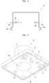
- FIG. 3 is a front view illustrating a bracket according to an embodiment of the present disclosure
- FIG. 4 is a bottom perspective view of the cover according to an embodiment of the present disclosure
- FIG. 5 is a front view of the fixing body according to an embodiment of the present disclosure
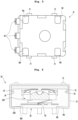
- FIG. 6 is a sectional view taken along line I-I' of FIG. 1 .
- the bracket 10 may include the support plate 18 inclined while extending from the connection plate 13.
- a plurality of support plates 18 may be provided.
- the plurality of support plates 18 may include a first support plate 18a and a third support plate 18c that are bent from the connection plate 13a that forms one side surface of the bracket 10, and a second support plate 18b and a fourth support plate 18d that are bent from a connection plate 13b forming an opposite side surface facing the one side.
- connection plate 13 forming one side surface of the bracket 10 is called a first connection plate 13a and the connection plate 13 facing the first connection plate 13a is called a second connection plate 13b.
- connection guide 14 formed on the first connection plate 13a is called a first connection guide 14a
- connection guide 14 formed on the second connection plate 13b is called a second connection guide 14b.
- the first support plate 18a and the third support plate 18c may be positioned while facing the second support plate 18b and the fourth support plate 18d. In other words, the first support plate 18a and the third support plate 18c may be symmetrical with the second support plate 18b and the fourth support plate 18d.
- Each support plate 18 may be inclined toward the center of the bracket 10. In other words, the support plate 18 may be inclined while extending upward from the connection plate 13.
- the support plate 18 may extend along a virtual extension line "c" drawn upward at a predetermined angle "a” from a virtual horizontal line “H” drawn from a lower end portion of the connection plate 13. Accordingly, the support plate 18 may form the predetermined angle "a” with the virtual horizontal line "H".
- the predetermined angle "a" may be defined as an acute angle.
- the above-described support plate 18 bent to be inclined upward couples and/or supports the fixing body 30 to the upper portion, an influence exerted on the fixing body 30, the cover 20, and the bracket 10 by the rotation of the rotating body 100 may be minimized. Accordingly, the deformation caused by the drawing force outward, the shaking due to the rotation, or the clearance resulting from the repeated rotation may be minimized.
- the cover 20 may further include a front guide shaft 25 and a rear guide shaft 26 for coupling the elastic ring 200.
- the front guide shaft 25 may protrude downward from the bottom surface of the cover 20.
- the front guide shaft 25 and the rear guide shaft 26 may be formed symmetrically with respect to the center of the shaft guide 21.
- the front guide shaft 25 and the rear guide shaft 26 may be inserted into guide holes of the elastic ring 200, which correspond to the front guide shaft 25 and the rear guide shaft 26, respectively, in the front-rear direction. Accordingly, the elastic ring 200 may be fixed the front guide shaft 25 and the rear guide shaft 26.
- cover 20 may further include a fixing protrusion 29 to fix and support the position of the elastic ring 200.
- the fixing protrusion 29 may be formed to make close contact with opposite end portions of front fixing parts 230 (see FIG. 10 ) of the elastic ring 200.
- a pair of fixing protrusions 28 may be formed to protrude from the bottom surface of the cover 20.
- the front guide shaft 25 may be interposed between the pair of fixing protrusions 28.
- the cover 20 may further include a mounting protrusion 27 to be mounted to a right position of the fixing body 30 and coupled with the fixing body 30.
- the mounting protrusion 27 may protrude from the bottom surface of the cover 20 to be inserted into the inner space of the fixing body 30.
- a pair of mounting protrusions 27 may be formed.
- the mounting protrusions 27 may be positioned outside of the fixing protrusion 29.
- cover 20 may further include a seating end portion 21a positioned at a lower end portion of the shaft guide 21.
- the seating end portion may make contact with a shaft stopper 120 of the rotating body 100 to be described.
- the seating end portion 21a may be seated on the shaft stopper 120.
- the seating end portion 21a makes contact with the shaft stopper 120 to maintain the space between the bottom surface of the cover 20 and the protrusion of the rotating body 100.
- the seating end portion 21a and the shaft stopper 120 may preserve the space in which the elastic ring 200 is installed. Accordingly, the elastic ring 200 may be prevented from being deformed or broken.
- cover 20 may further include an outer wall 24 extending downward vertically along the outer rim of the cover 20.
- the outer wall 24 may include a step formed along the rim of the bottom surface of the cover 20.
- the outer wall 24 may be coupled to an upper end portion of the fixing body 30 to make close contact with the upper end portion of the fixing body 30.
- the fixing body 30 may further include an inner wall 34 having a step formed inward along an upper end portion of the fixing body 30.
- the inner wall 34 may extend upward to be stepped from the upper end of the fixing body 30.
- the inner wall 34 may be formed in a shape corresponding to the outer wall 24.
- the cover 20 may cover the open top surface of the fixing body 30 such that the outer wall 24 is in close contact with the outside of the inner wall 34.
- the fixing body 30 may further include a support groove 38 into which the support plate 18 is inserted.
- the support groove 38 may be formed on the bottom surface of the fixing body 30.
- the support groove 38 may be formed at a position corresponding to the support plate 18.
- the support groove 38 may be recessed and inclined upward at a predetermined angle "a" from the lower end portion of the fixing body 30 by the predetermined angle "a".
- the fixing body 30 may include a plurality of support grooves 38 that may be formed in number corresponding to the number of the support plates 18.
- the support grooves 38 may include a first support groove 38a, into which the first support plate 18a is inserted, a second support groove 38b in which the second support plate 18b is inserted, a third support groove 38c into which the third support plate 18c is inserted, and a fourth support groove 38d in which the fourth support plate 18d is inserted.
- the bracket 10, the cover 20, and the fixing body 30 may be stably maintained in air tightness and sealing through the configuration of the bracket 10, the cover 20, and the fixing body 30. Therefore, there is an effect of preventing a urethane coating liquid from being infiltrated.
- FIG. 7 is a perspective view of the rotating body according to an embodiment of the present disclosure
- FIG. 8 is an enlarged view of part A of FIG. 7
- FIG. 9 is a top view of the rotating body when viewed from the top according to an embodiment of the present disclosure.
- the rotating body 100 may include a base 110 coupled to the contact plate 50 and a shaft 105 extending upward from the center of the base 110.
- the base 110 may have a disc shape.
- the contact plate 50 may be coupled to the bottom surface of the base 110. As the rotating body 100 rotates, the contact plate 50 may rotate in the inner space of the fixing body 30.
- the rotating body 100 may be connected with a handling unit or handling device allowing a user to handle the rotation.
- a handling unit or handling device allowing a user to handle the rotation.
- the knob connection groove 108 recessed in the top surface of the shaft 105 may be coupled to the handling unit to transfer the torque provided by the user to the rotating body 100.
- the rotating body 100 may further include a shaft stopper 120 extending along a circumferential surface of the shaft 105 by a predetermined length.
- the shaft stopper 120 may protrude in the radial direction from the lower outer circumferential surface of the shaft 105 and extend in the circumferential direction.
- the shaft stopper 120 may be formed to extend in the radial direction from the shaft 105 by a predetermined length.
- the shaft stopper 120 may form a step difference from the lower portion of the shaft 105.
- the shaft stopper 120 may extend upwardly from the base 110 to have a diameter greater than the diameter of the shaft 105.
- the shaft stopper 120 may have a cylindrical shape with a short length.
- the shaft stopper 120 may extend from the base 110 to a position higher than the elastic ring 200. Accordingly, when drawing force outward or force is applied to the rotating body 100 outwardly or in the shaft direction, since the step difference of the shaft stopper 120 makes contact with the seating step part 21a, the elastic ring 200 may be prevented from being deformed and/or broken.
- the rotating body 100 includes protrusions 130 and 140 protruding in the axial direction and the radial direction, respectively.
- a plurality of protrusions 130 and 140 are provided on the top surface and the circumferential surface (or the side surface) of the base 110 in the circumferential direction, thereby forming a roughness shape.
- the rotating body 100 may include protrusions 130 and 140 protruding in two directions perpendicular to each other.
- the protrusions 130 and 140 may make contact with the elastic ring 200 or the leaf spring 60 while rotating.
- the elastic ring 200 may provide elastic force to the protrusions 130 and 140 in the axial direction
- the leaf spring 60 may provide the elastic force to the protrusions 130 and 140 in the side direction.
- the protrusions 130 and 140 may include a side protrusion 130 protruding in a radial direction along the circumferential surface of the base 110 and an upward protrusion 140 protruding in a direction perpendicular to the side protrusion 130.
- the side protrusion 130 and the upward protrusion 140 protude from the base 110 in two different directions.
- the side protrusion 130 and the upward protrusion 140 extend in the side direction and the axial direction of the base 110 to be perpendicular to each other from a common center O.
- side protrusion 130 and the upward protrusion 140 may extend in the side direction and the upward direction from the same position and may be provided in the circumferential direction of the base 110.
- the side protrusion 130 and the upward protrusion 140 may be formed perpendicularly to each other such that a starting point and an end point protruding from the base 110 are the same. In other words, the side protrusion 130 and the upward protrusion 140 are not provided alternately.
- the rotating state may be acoustically informed to the user.
- a plurality of side protrusions 130 and upward protrusions 140 may be formed in the circumferential surface of the base 100.
- the side protrusion 130 may protrude in the side direction (or radial direction) from the circumferential surface of the base 100.
- the side protrusion 130 may have a surface which is gently curved and faces the outside.
- the top surface and the lower surface of the side protrusion 130 may be formed as planes aligned in line with the base 110.
- the upward protrusion 140 is formed to protrude upward from the top surface of the base 110.
- the top surface of the upward protrusion 140 may have a surface which is gently curved.
- opposite side surfaces of the upward protrusion 140 may be formed as curved surfaces to improve the stiffness and the precision of the position.
- the side protrusion 130 and the upward protrusion 140 may be named protrusions of the rotating body 100.
- the protrusions 130 and 140 of the rotating body 100 may have surfaces gently curved in the protrusion direction to make stable and smooth rotation-contact with the leaf spring 60 or the elastic ring 200
- the side protrusion 130 and the upward protrusion 140 may have a semicircular cross section.
- the side protrusion 130 and the upward protrusion 140 may extend with different slops due to the difference in the design value (for example, durability) between the elastic ring 200 and the leaf spring 60.
- the side protrusion 130 may be formed to have a steeper slop at a point of first making contact with the leaf spring 60, so as to generate a rhythmical.
- the upward protrusion 140 may be formed to have a gentler slope at a point first making contact with the elastic ring 200 to provide smooth rotational operation feeling.
- the upward protrusion 140 may have a smaller slope of the curved surface protruding from the base 110 than the side protrusion 130.
- the protruded curved surface of the upward protrusion 140 may be understood as a top surface of the upward protrusion 140 and the protruded curved surface of the side protrusion 130 may be understood as an outer surface of the side protrusion 130. Therefore, the top surface of the upward protrusion 140 may be formed more gently than the outer surface of the side protrusion 130.
- the distance V from a common midpoint "O" to the uppermost point of the upward protrusion 140 is greater than the distance "R" between the common midpoint "0" and the outermost point of the side protrusion 130.
- the maximum length V of the upward protrusion 140 extending upward from the base 110 may be shorter than the maximum length R of the side protrusion 130 extending in the radial direction from the base 110. That is, the maximum extension length "V" of the upward protrusion may be shorter than the maximum extension length "R" of the side protrusion.
- the radius of the longitudinal sectional surface of the upward protrusion 140 may be smaller than the radius of the cross sectional surface of the side protrusion 130.
- the longitudinal surface of the upward protrusion 140 may have an oval shape having a smaller radius toward the uppermost point.
- the cross sectional surface of the side protrusion may have an oval shape having a radius increased toward the outermost point.
- the elastic ring 200 smoothly slides to the top surface, which is gentle and low, of the upward protrusion 140 while rotating and making contact with the upward protrusion 140, the rotational operation feeling of the handling unit by the user may be improved.
- the leaf spring 60 Since the leaf spring 60 makes friction or collides with a greater deformation degree due to a higher slop or height while rotating and making contact with the side protrusion 130, the leaf spring 60 generates a loud and rhythmical sound.
- the rotating body 100 may further include an extending rib or a plurality of extending ribs 150 provided at a lower portion of the rotating body 100 while extending in the radial direction.
- the extending ribs 150 may extend in the radial direction from the outer circumferential surface of the shaft 105. In detail, the extending ribs 150 may extend in the radial direction from the outer circumferential surface of the shaft stopper 120.
- the extending rib 150 may extend from the shaft stopper 120 to the upward protrusion 140.
- the extending rib 150 may protrude in the radial direction from the circumferential surface (or side surface) of the shaft stopper 120 and may extend to the side surface of the upward protrusion 140.
- the extending rib 150 may be formed to have a height which is decreased in the radial direction. In other words, the extending rib 150 may be formed to have a height decreased in an extending direction extending from the shaft stopper 120 to the upward protrusion 140. In other words, the top surface of the extending rib 150 may be formed to be inclined.
- the extending ribs 150 may be formed in a number corresponding to the upward protrusions 140.
- the extending rib 150 may reinforce the stiffness of the upward protrusion 140.
- the extending rib 150 may perform a guide to make the contact between the elastic ring 200 and the upward protrusion 140 at a right position.
- the elastic ring 200 may make contact with the upward protrusion 140 at a wrong position by deviating from the right position due to the repetitive rotation of the rotating body 100. As the case is repeated, the elastic ring 200 and the rotating body 100 may be abraded or cracked.
- the extending rib 150 may prevent the elastic ring 200 from deviating from the right position due to the rotation of the elastic ring 200.
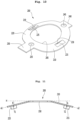
- FIG. 10 is a perspective view illustrating an elastic ring according to an embodiment of the present disclosure
- FIG. 11 is a front view of the elastic ring according to an embodiment of the present disclosure.
- the elastic ring 200 may be formed to have a tapered shape.
- the elastic ring 200 may include a first bending part 210 bent downward from one side thereof and a second bending part 220 bent downward from an opposite side thereof.
- the first bending part 210 and the second bending part 220 may be formed to be symmetrical to each other.
- the second bending part 220 may form a remaining semicircle of the elastic ring 200.
- first bending part 210 and the second bending part 220 are bent from the central portion of the elastic ring 200 downward of opposite sides thereof, force may be applied to the rotating body 100 in the central axis.
- a virtual horizontal line “H” may be set for the convenience of explanation of the first bending part 210 and the second bending part 220.
- the virtual horizontal line “H” may be understood as a horizontal line extending in parallel to the extension plane of a front fixing part 230.
- the first bending part 210 may be bent downward at a predetermined bending angle "b" from the virtual horizontal line "H".
- the bending angle "b" may include an acute angle.
- the second bending part 220 may be bent downward at a predetermined bending angle "b" from the virtual horizontal line.
- the elastic ring 220 may include elastic protrusions 215 and 225 making contact the protrusion of the upward protrusion 140.
- the elastic protrusions 215 and 225 may be formed to protrude downward from the elastic ring 220.
- the protrusion portions of the elastic protrusions 215 and 225 may be rounded. Therefore, the bottom surfaces of the elastic protrusions 215 and 225 may have gentle curved surfaces.
- the elastic protrusions 215 and 225 may protrude downward from both the bending portions 210 and 220 such that opposite sides of the elastic protrusions 215 and 225 are cut out.
- the elastic protrusions 215 and 225 may include a first elastic protrusion 215 and a second elastic protrusion 225 formed to be symmetrical to each other.
- the first elastic protrusion 215 and the second elastic protrusion 225 may be symmetrical to each other.
- the elastic ring 200 may press the rotating body 100 in at least two points symmetrical to each other.
- the first elastic protrusion 215 may be formed to protrude downward T2 perpendicular to a virtual extension line e2 drawn in an extension direction of the first bending part 210 while forming the bending angle "b".
- the second elastic protrusion 225 may be formed to protrude downward T1 perpendicular to a virtual extension line e1 drawn in an extension direction of the second bending part 220 while forming the bending angle "b".
- the elastic protrusions 215 and 225 may act as resultant force F of force FL pressing vertically downward against the upward protrusion 140 and force Fc pressing the upward protrusion 140 toward the center.
- the first elastic protrusion 215 and the second elastic protrusion 225 may be formed to have widths smaller than the widths of the bending parts 210 and 220 extending in a circular shape.
- the elastic ring 200 may include elastic reinforcing holes 218 and 219 to reinforce the elastic force of the elastic protrusions 215 and 225.
- the elastic reinforcing holes 218 and 219 may be defined as spaces spaced apart in the vertical direction between the bottom surface of the elastic ring 200 and the elastic protrusions 215 and 225.
- a portion of a top surface of the first bending part 210 may be recessed downward such that the first elastic protrusion 215 protrudes downward in the vertical direction from the first bending part 210.
- the first elastic protrusion 215 may have openings 218 spaced apart bi-directionally from the first bending part 210.
- the spaces, which are open bi-directionally between the first elastic protrusion 215 and the first bending part 210, may be named a first elastic enhancing hole 218.
- the first elastic enhancing hole 218 forms a space open downward from the first bending part 210, the first elastic protrusion 215 may be guided to be easily elastically deformed.
- the second elastic protrusion 225 may form the second elastic enhancing hole 219.
- the elastic ring 200 may include elastic enhancing holes 218 and 219 provided at opposite sides of the elastic protrusions 215 and 225 and defined as openings to space the elastic protrusions 215 and 225 from the bending parts 210 and 220.
- the elastic ring 200 may further include a front fixing part 230 and a rear fixing part 240 to be fixed to the cover 20 or the fixing body 30.
- the front fixing part 230 and the rear fixing part 240 may be provided in the form of a rectangular flat plate.
- the front fixing part 230 may include a front end portion that protrudes while extending forward.
- the rear fixing part 240 may include a rear end portion protruding rearward while extending. However, the rear fixing part 240 may be shorter than the front fixing part 230.
- Opposite end portions of the front fixing part 230 may be fitted between the fixing protrusions 29 of the cover 20.
- the front end portion of the front fixing part 230 may be inserted or seated in the fixing body 30.
- the rear end portion of the rear fixing part 240 may be inserted or seated in the fixing body 30
- the front fixing part 230 may include a front guide hole 235 into which the front guide shaft 25 is inserted.
- the rear fixing part 240 may include a rear guide hole 245 into which the rear guide shaft 26 is inserted.
- the elastic ring 200 may be stably supported by the cover 20 and the fixing body 30. Accordingly, the elastic ring 200 may stably press the upward protrusion 140 of the rotating body 100.
- the front fixing part 230 and the rear fixing part 240 may be positioned at the center of the elastic ring 200. Therefore, the first bending part 210 and the second bending part 220 may be formed symmetrically to each other with respect to the fixing parts 230 and 240.
- front fixing part 230 and the rear fixing part 240 may provide references of front and rear positions of the elastic ring 200.
- the front fixing part 230 and the rear fixing part 240 may guide the elastic ring 200 such that the elastic ring 200 is mounted in a right position of the cover 20 or the fixing body 30.
- the elastic ring 200 may provide elastic force to the protrusions 130 and 140 of the rotating body 100 together with the leaf spring 60, the elastic ring 200 may have a mechanical property different from the one of the leaf spring 60.
- the elastic ring 200 may be formed to have a greater elastic coefficient, stiffness, and durability than the leaf spring 60.
- the elastic ring 200 provides the rotating body 100 with an elastic force in a range that is greater than the elastic force provided from the leaf spring 60 to the side protrusion 130, the elastic ring 200 may serve as the major cause of torque applied to the rotating body 100.
- the leaf spring 60 is designed to have a significantly low elastic coefficient as compared with that of the elastic ring 200, even if the degree of deformation of the leaf spring 60 is relatively large, the influence of the overall elastic force exerted on the rotating body 100 may be made much smaller in the leaf spring 60 than in the elastic ring 200.
- the leaf spring 60 may provide a relatively small unit of torque to the rotating body 100.
- allowable torque values may be set in 10 units or 100 units through the design of the elastic ring 200 and the upward protrusion 140.
- the allowable torque value may be set in one or less unit through the design of the leaf spring 60 and the side protrusion 130.
- the value of 300 or 310 may be set through the design of the elastic ring 200 and the upward protrusion 140, and the value of 12 or 2 may be set through the design of the leaf spring 60 and the side protrusion 130.
- the main function of the elastic ring 200 is to improve the rotational operation feeling, and it can be understood that the main function of the leaf spring 60 is to improve the rotation sound.
- FIG. 12 is an assembled perspective view illustrating a coupling relationship between the rotating body, the elastic ring, and the leaf spring according to an embodiment of the present disclosure
- FIG. 13 is a sectional view taken along line J-J 'of FIG. 12
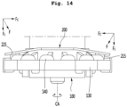
- FIG. 14 is a front view of FIG. 12 .
- the protrusions 130 and 140 of the rotating body 100 may make contact with the elastic ring 200 and the leaf spring 60.
- the elastic protrusions 215 and 225 are elastically restored when the elastic protrusions 215 and 225 are positioned in the valleys formed by the plurality of the upward protrusions 140. In addition, the elastic protrusions 215 and 225 are most elastically deformed when they are positioned on the ridges of the upward protrusions 140.
- the central protrusion 65 is elastically restored when the central protrusion 65 is positioned in the valleys formed by the plurality of side protrusions 130.
- the central protrusion 65 is most elastically deformed when the central protrusion 65 is positioned on the ridge of the side protrusion 130.
- the elastic protrusions 215 and 225 may act as resultant force F of force FL pressing vertically downward against the upward protrusion 140 and force Fc pressing the upward protrusion 140 toward the center of the rotating body 100.
- the elastic ring 200 may downward apply force to the rotating body 100 and force toward the central axis CA.
- This action of the force F enables the rotation of the rotating body 100 to be stably maintained with respect to the central axis CA. Therefore, it is possible to reduce the shaking due to the rotation of the rotating body 100, and to minimize the deviation from the rotation radius, thereby improving the rotation stability.
- the elastic ring 200 press the rotating body 100 vertically downward, the shaking and the vibration may be reduced, and the rotation stability may be improved as compared with when a conventional rotating body is supported only in the transverse direction or side direction.
- the inner space of the fixing body 30 may be formed in a compact size. Accordingly, the space formed from the protrusions 130 and 140 of the rotating body 100 in the side direction and radial direction may be minimized. Accordingly, the clearance between components, which is caused by the repeated rotation, may be minimized.
- the elastic ring 200 may be named a first elastic unit.
- the leaf spring 60 may be named a second elastic ring, and the auxiliary leaf spring 70 may be named a third elastic ring.
Landscapes
- Rotary Switch, Piano Key Switch, And Lever Switch (AREA)
Description
- The present disclosure relates to a rotary switch.
- A rotary switch may switch a contact and select a circuit through rotation operation. Accordingly, as the rotary switch performs an on/off control of an individual switch through the rotation operation, the configuration of the circuit is varied.
- The rotary switch may generate a pulse signal by rotating clockwise or counterclockwise. Accordingly, the rotary switch may be called a rotary encoder switch.
- The rotary switch is provided in various products. For example, the rotary switch may be provided in a washing machine. In this case, the rotary switch may be used as a handling device of the washing machine. Accordingly, a user may select a desired operation mode of the washing machine by rotating the rotary switch.
- In general, the rotary switch may include a handling unit rotated and operated by the user, a rotating body rotating through the rotation of the handling unit, and a fixing body allowing the rotating body to be received therein and making sliding contact with the rotating body.
- In addition, the fixing body may include a switch pattern connected with a terminal. In addition, the rotating body may include a metallic plate making sliding-contact with the switch pattern through the rotation. The on-off control of the switch may be performed through the sliding-contact between the metallic plate and the switch pattern.
- A conventional rotary switch has the following problem.
- First, a space is formed in the rotating body in the longitudinal and transverse directions, so the shaking and the vibration are relatively large during rotation.
- Second, according to the conventional rotating body, a concavo-convex part formed at a circumferential surface thereof determines the rotational sound and torque necessary for the rotation. Accordingly, the user feels that the rotational operation feeling, which allows the user to tactilely recognize the rotation, is coarse and feels that the rotational sound, which is dependent on the rotation of the operation part and allows the user to audibly recognize the rotation, is relatively blunt.
- Third, it is difficult to finely adjust an allowable torque value allowing the rotation in the procedure of manufacturing the rotary switch. In other words, it is difficult to perform fine tuning for allowable torque for the rotation of the rotary switch.
- Fourth, by the handling of the user, force applied in the shaft direction of the rotating body or drawing force outward direction may be applied to the rotary switch. In this case, the leaf spring and the rotating body may be easily deformed (or broken) by force applied in the shaft direction or drawing force outward.
- Fifth, the roughness (or protrusion) may be cracked due to the repeated rotation of the rotating body, thereby reducing the lifespan of the product.
- Sixth, since only the fixing body and the cover are coupled to receive the rotating body, the durability of the rotary switch may be relatively degraded.
- Information on the prior art will be described as follows.
-
KR10-2008-0044464 -
KR100670540 B1
CN 201 122 548 Y relates to a positioning structure for a multiway rotary switch. The positioning structure comprises an insulation stool body which is provided with a holding space for holding a conductive terminal group, a butt terminal group, a baffle plate and a knob. The pins of the conductive terminal group respectively extend to be exposed outside the insulation stool body. The butt terminal group is positioned above the conductive terminal group and is adjacent to the conductive terminal group to form a preset gap, and elastic propping parts are respectively arranged on the butt terminals. The baffle plate is positioned above the butt terminal group and is provided with a plurality of openings. The knob is positioned above the baffle plate, and is provided with a turn table with a convex turning rod, a propping block is arranged at the bottom of the turn table, a plurality of limiting clipping grooves are arranged on the circumference of the outer ring of the turn table, and a limiting wing panel which can be elastically distorted is arranged outside the turn table. A cover body is closed and covered above the insulation stool body, and an operating hole for the turning rod of the turn table to protrude is arranged on the surface of the cover body. - The invention is specified by the
independent claim 1. Preferred embodiments are defined in the dependent claims. The present disclosure is suggested to solve the problem of the conventional rotary switch, and is to provide a rotary switch which minimizes a space separated from a rotating body. - The present disclosure is to provide a rotary switch which minimizes the clearance between components, which is caused due to rotation.
- In addition, the present disclosure is to provide a rotary switch capable of relatively improving the rotational operation feeling and a rotational sound allowing a user to be impressed as a high-quality product.
- In addition, the present disclosure is to provide the structure of a rotary switch allowing the design of relatively fine allowable torque for rotation.
- In addition, the present disclosure is to provide a rotary switch capable of preventing the deformation and the breakdown even if drawing force applied outward or force applied in the shaft direction act
- In addition, the present disclosure is to provide a rotary switch capable of minimizing cracks which are caused due to the repeated rotation of a rotating body.
- Further, the present disclosure is to provide the structure of a rotary switch in which the coupling between components is relatively strong and stable.
- The invention is specified by the independent claim. Preferred embodiments are defined in the dependent claims. In order to accomplish the objects, a rotary switch may include a fixing body, a rotating body having received in the fixing body to rotate, a cover coupled to an upper portion of the fixing body to allow the rotating body to pass through the cover, a first elastic body positioned under the cover to make contact with the protrusion, which is formed in the rotating body in the shaft direction, while rotating; and a second elastic body positioned under the cover to make contact with the protrusion, which is formed in the rotating body in the radial direction, while rotating. Accordingly, the first elastic body and the second elastic body may improve the quality of the rotary switch in the rotational operation feeling and the rotational sound.
- The first elastic unit may support the rotating body in the axial direction. In addition, the second elastic unit may support the rotating body in the side direction. Accordingly, the rotation of the rotating body may be performed stably, and the generation of clearance between the components may be minimized.
- The first elastic body may have a ring shape such that the rotating body passes through the center of the first elastic body and provides force toward the center of the rotating body. The second elastic body may have a plate shape.
- The first elastic body may include: a first bending part and a second bending part which are bent downward symmetrically to each other.
- The first elastic body may press the rotating body in at least two points symmetrical to each other.
- The first elastic body may include: a first elastic protrusion protruding downward from the first bending part and a second elastic protrusion protruding downward from the second bending part.
- The first elastic body may be formed therein with elastic enhancement holes defined as spaces away from the first elastic protrusion and the second elastic protrusion in a vertical direction.
- The rotating body may include: a base having a circular shape and a shaft extending upward from the center of the base. The protrusions may include a side protrusion protruding in the radial direction along a circumferential surface of the base and an upward protrusion protruding perpendicularly to the side protrusion.
- The upward protrusion may protrude with a slope, which may be gentler than the side protrusion, from the base.
- A plurality of upward protrusions and a plurality of side protrusions may be formed in a circumferential direction of the base.
- The rotating body may further include a shaft stopper having a step along a lower circumference of the shaft. The shaft stopper may extend from the base to a position higher than the first elastic body.
- The cover may include a shaft guide having an opening allowing the shaft to pass through the opening and a guide shaft extending downward from a bottom surface of the cover to fix the first elastic body.
- The rotating body may further include an extending rib extending from the shaft toward the upward protrusion. The extending rib may extend so that a height gradually decreases toward the upward protrusion.
- The rotary switch may further include a bracket coupled to an upper portion of the cover. The bracket may include a support plate extending upwardly and inclined so as to be inserted into a support groove recessed from a bottom surface of the fixing body.
- The fixing body may include: coupling bosses protruding from opposite side surfaces thereof and a coupling shaft extending upward to guide coupling the cover to the bracket. The coupling bosses may be inserted into boss holes formed in opposite side surfaces of the bracket.
- The first elastic body may be called an elastic ring, and the second elastic body may be called a leaf spring.
- The protrusions formed on the rotating body may protrude in the axial direction and the radial direction of the rotating body, respectively. Accordingly, there is suggested the structure of the rotary switch capable of functionally separating the rotational operation feeling and the rotational sound in the protrusion direction of the protrusion, which is different a conventional art. Therefore, the rotary switch according to the embodiment of the present disclosure may optimize the rotational operation feeling and the rotational sound in terms of sensibility of the user.
- The elastic ring makes contact with the protrusion, which protrudes in the axial direction of the rotating body, while rotating. According to the elastic ring pressing the rotating body in the axial direction, the rotating body may minimize the space in the axial direction (or vertical direction) as compared with the rotary switch.
- In addition, the elastic ring is interposed between the bottom surface of the cover and the base of the rotating body and provides force to the rotating body. Accordingly, the rotation stability and the rotational operation feeling of the rotary switch may be improved.
- The upward protrusion protrudes upward from the rotating body and the side protrusion protrudes in the side direction of the rotating body.
- The surfaces of the upward protrusion and the side protrusion, which make contact with the elastic ring or the leaf spring, may be curved.
- In addition, the leaf spring making contact with the side protrusion while rotating may be provided under the elastic ring. The side protrusion making contact with the leaf spring may instantly generate cheerful rotational sound.
- In addition, the upward protrusion, which makes contact with the elastic ring, in the vertical direction of the rotating body may provide the soft rotational operation feeling to the user.
- In addition, the upward protrusion and the side protrusion may be formed in a semicircular shape to make stable rotation contact.
- Further, the upward protrusion and the side protrusion may be formed with mutually different slopes due to the difference in durability between the leaf spring and the elastic ring.
- In addition, to make smooth rotation contact with the elastic ring, the upward protrusion may have a smaller inclination angle of the curved surface protruding from the base than the side protrusion.
- In addition, the upward protrusion and the side protrusion may be positioned perpendicularly to each other and corresponding to each other, thereby generating the rotational sound depending on the rotation of the rotary switch. For example, a diameter of the upward protrusion in the longitudinal sectional surface may be identical to the diameter of the side protrusion in the cross sectional surface. In other words, the upward protrusion and the side protrusion may have the same starting point and end point for protruding from the base of the rotating body. Accordingly, the rotational sound may be generated corresponding to the rotational operation of the user.
- In addition, the upward protrusion and the side protrusion may extend from a common point to be perpendicular to each other. Accordingly, the rotational sound may be generated corresponding to the rotation of the rotary switch.
- The upward protrusion and the side protrusion may have oval-shaped sectional surfaces. For example, the upward protrusion may be formed to have a radius decreased from the central point (O) toward the highest point and the side protrusion may be formed to have a radius increased from the central point (O) toward the outermost point.
- In addition, the upward protrusion may be formed such that the maximum extension length (V) of the upward protrusion may be shorter than the maximum extension length (R) of the side protrusion.
- Further, a radius of the upward protrusion in the longitudinal sectional surface may be identical to the radius of the side protrusion in the cross sectional surface.
- Meanwhile, to provide elastic force to the upward protrusion, the elastic ring may include an elastic protrusion protruding downward.
- At least two elastic protrusions may be provided.
- In addition, a plurality of elastic protrusions may be positioned to be symmetrical to each other. Accordingly, the elastic ring may guide the stable rotation since the elastic ring presses the upward protrusion in at two points symmetrical to each other.
- Further, to provide a force directed toward the central axis of the rotating body, the elastic ring may be formed to be tapered at opposite sides thereof.
- In other words, the elastic ring may include a first bending part bent to be inclined downward at one side and a second bending part bent to be inclined downward at an opposite side thereof.
- Further, the first bending part and the second bending part may be formed to have the same inclination angle that the first bending part and the second bending part are bent from the center of the elastic ring.
- In addition, the first bending part and the second bending part may be formed to be symmetrical to each other. Accordingly, the force acting on the rotating body from the elastic ring faces the center, so that stable rotation of the rotating body may be guided.
- In addition, the elastic protrusion formed on the elastic ring may be formed to protrude downward from the first bending part and the second bending part, respectively. For example, the elastic protrusions may protrude perpendicularly to a bottom surface of each of the first bending part and the second bending part.
- In addition, the elastic protrusions may be formed to be rounded downward.
- Further, to enhance the elastic force of the elastic protrusion, the elastic ring may have elastic enhancing holes formed at opposite sides of the elastic protrusion and defined as openings to space the elastic protrusion from the bending part (the first bending part and the second bending part)
- In addition, the elastic ring may be provided in the type of a ring to make contact with the upward protrusion under the ring. Accordingly, the clearance, which may occur in the vertical direction (or shaft direction), may be minimized.
- In addition, the upward protrusion of the rotating body making contact with the elastic ring may be designed to have allowable torque values (unit kgf·cm) in the 10 or 100 units such that the fine tuning of the allowable torque is possible in the procedure of manufacturing the rotary switch. The side protrusion of the rotating body making contact with the leaf spring may be designed to have an allowable torque value of 1 unit (unit kgf-cm) or less.
- To minimize the acting of force applied in the side direction or drawing force outward with respect to the elastic ring and the leaf spring, the support plate of the bracket may be formed to be inclined upward, and the support groove of the fixing body may be recessed to correspond to the support plate.
- In addition, to minimize the force applied to the elastic ring in the side direction or the drawing force applied outward to the elastic ring, a shaft stopper having a step difference along the lower circumference of the shaft of the rotating body may make contact with the bottom surface of the cover.
- In addition, to minimize the cracks of the elastic ring or the upward protrusion which is caused due to the repeated rotation, the extending rib extending in the radial direction from the shaft stopper to the upward protrusion may be provided.
- The extending rib may stably guide the contact between the elastic ring and the upward protrusion.
- In addition to strongly couple the bracket to the fixing body, the fixing body may include a coupling boss protruding from the outer circumferential surface of the fixing body.
- The coupling boss may be inserted into the boss hole formed in the connection plate of the bracket.
- In addition, for stable fixation of the bracket, the cover, and the fixing body, the fixing body may include a coupling shaft extending upward. The coupling shaft may be positioned so as to sequentially pass through the coupling hole in the cover and the insertion hole in the bracket. In other words, the coupling shaft may perform a function of guiding the coupling of the cover and the bracket.
- Further, the rim of the cover and the fixing body may form steps corresponding to each other. In detail, an inner wall extending vertically upward is provided on the upper end portion of the fixing body to form the step and an outer wall extending vertically downward from the outer circumference is formed at the lower end portion of the cover to form the step. In addition, the outer wall and the inner wall may be coupled to each other to be in close contact with each other.
- In addition, the bracket may be positioned on the cover such that the rotating body passes through the bracket. In addition, the bracket may be coupled to the cover and the fixing body. Accordingly, the stable coupling and support between components are maintained, so the rotation stability of the rotary switch is improved.
- According to the present disclosure, the protrusions of the rotating body and the elastic ring, which are separated from each other functionally and structurally, are provided to minimize the space separated apart from the rotating body and the clearance between components, thereby reducing the shaking and the vibration. In addition, the rotation stability of the rotary switch is improved.
- According to the present disclosure, when the user rotates and manipulates the handling unit, elastic force is applied to the side protrusion and the upward protrusion of the rotating body, thereby minimizing the vibration. Accordingly, the relatively smooth rotational operation feeling may be provided. In addition, the more cheerful rotational sound may be provided. Accordingly, the product impresses a user as high-quality product in terms of sensibility.
- According to the present disclosure, the fine tuning of the allowable torque is possible in the procedure of manufacturing the rotary switch, which is different from the conventional rotary switch. In addition, high-quality rotational operation feeling may be provided. Therefore, the reliability of the product is improved.
- According to the present disclosure, the support plate of the bracket is formed to be bent, and the support groove of the fixing body is recessed to correspond to the support plate. Accordingly, the rotary switch may be prevented from being broken or deformed by the force applied to the rotary switch in the shaft direction or the drawing force applied outward from the rotary switch. In other words, the durability of the product is improved, so the lifespan of the product is improved.
- According to the present disclosure, the extending rib extending to the upward protrusion guides the rotation contact between the elastic ring and the upward protrusion due to the rotation of the rotating body, and the stiffness of the upward protrusion may be reinforced. Accordingly, the cracks of the elastic ring or the upward protrusion may be minimized. Accordingly, the lifespan of the product extends.
- In addition, since the fixing body, the cover, and the bracket are mutually strongly coupled and supported, the durability of the rotary switch is improved.
- In addition, since the outer wall and the inner wall are coupled to make contact with each other, the fixing body and the cover may be stably maintained with air tightness and sealing.
-
-
FIG. 1 is a perspective view illustrating a rotary switch according to an embodiment of the present disclosure. -
FIG. 2 is an exploded perspective view illustrating the configuration of the rotary switch according to an embodiment of the present disclosure. -
FIG. 3 is a front view illustrating a bracket according to an embodiment of the present disclosure. -
FIG. 4 is a bottom perspective view of the cover according to an embodiment of the present disclosure. -
FIG. 5 is a front view of the fixing body according to an embodiment of the present disclosure. -
FIG. 6 is a sectional view taken along line I-I' ofFIG. 1 . -
FIG. 7 is a perspective view of the rotating body according to an embodiment of the present disclosure. -
FIG. 8 is an enlarged view of part A ofFIG. 7 . -
FIG. 9 is a top view of the rotating body when viewed from the top according to an embodiment of the present disclosure. -
FIG. 10 is a perspective view illustrating an elastic ring according to an embodiment of the present disclosure. -
FIG. 11 is a front view of the elastic ring according to an embodiment of the present disclosure. -
FIG. 12 is an assembled perspective view illustrating a coupling relationship between the rotating body, the elastic ring, and the leaf spring according to an embodiment of the present disclosure. -
FIG. 13 is a sectional view taken along line J-J 'ofFIG. 12 . -
FIG. 14 is a front view ofFIG. 12 . - Hereinafter, some embodiments of the present disclosure will be described in detail with reference to accompanying drawings. In adding the reference numerals to the components of each drawing, it should be noted that the identical or equivalent component is designated by the identical numeral even when they are displayed on other drawings. In addition, in the following description of an embodiment of the present disclosure, a detailed description of well-known features or functions will be ruled out in order not to unnecessarily obscure the gist of the present disclosure.
- In the following description of elements according to an embodiment of the present disclosure, the terms 'first', 'second', 'A', 'B', `(a)', and `(b)' may be used. These terms are merely intended to distinguish one component from another component, and the terms do not limit the nature, sequence or order of the constituent components. When a certain element is "liked to", "coupled to", or "connected with" another element, the certain element may be directly linked to or connected with the another element, and a third element may be "linked", " coupled ", or "connected" between the certain element and the another element.
-
FIG. 1 is a perspective view illustrating a rotary switch according to an embodiment of the present disclosure, andFIG. 2 is an exploded perspective view illustrating the configuration of the rotary switch according to an embodiment of the present disclosure. - Referring to
FIGS. 1 and2 , arotary switch 1 according to an embodiment of the present disclosure may include abracket 10. - The
bracket 10 may be stably engaged with other components positioned under thebracket 10. For example, acover 20 and a fixingbody 30 positioned under thebracket 10 may be firmly engaged with thebracket 10. - The
rotary switch 1 may further include therotating body 100 which is rotatable. - In detail, the
bracket 10 may be formed in the center thereof with acentral opening 11 open to allow ashaft 105 of therotating body 100 to pass through thecentral opening 11. For example, thecentral opening 11 may be formed in a circular shape. - In addition, the
bracket 10 may include a rectangular plate. In addition, thebracket 10 may include aninsertion hole 12 to guide the coupling with the fixingbody 30 in a vertical direction (or a shaft direction). Theinsertion hole 12 may be formed such that acoupling shaft 31 of the fixingbody 30 to be described later is inserted into and/or fixed to theinsertion hole 12. - The insertion holes 12 may be formed in a number corresponding to the
coupling shafts 31. - Further, the
bracket 10 may includeconnection plates 13 extending vertically downward from opposite edges of thebracket 10. Therefore, thebracket 10 may be opened in the front-rear direction. Theconnection plates 13 may be positioned on opposite sides of thebracket 10. For example, thebracket 10 may be formed in the shape of tongs. - The
connection plates 13 may be formed at opposite sides thereof with boss holes 15 that guide the coupling to the fixingbody 30. The boss holes 15 may be formed such thatcoupling bosses 33 to be described later are inserted into and fixed to the boss holes 15. The boss holes 15 may be formed in the number corresponding to thecoupling bosses 33. - Each
connection plate 13 may include aconnection guide 14 to guide the connection with external components. - The
connection guide 14 may be formed to extend downward from the central portion of theconnection plate 13. Theconnection guide 14 may be formed to be bent along the extending direction. - In addition, the
bracket 10 may include asupport plate 18 extending inward of thebracket 10 from theconnection plate 13. - The
support plate 18 may be formed to extend toward the center of thebracket 10 from a lower end portion of theconnection plate 13. In other words, thesupport plate 18 may be inclined while extending. The details thereof will be described below. - The
rotary switch 1 may further include acover 20. - The
cover 20 may be positioned under thebracket 10. Thecover 20 may be positioned to be inserted into or to pass through thecentral opening 11 of thebracket 10. - The
cover 20 may include ashaft guide 21 to guide ashaft 105 of therotating body 100. - The
shaft guide 21 may be formed at the center of thecover 20. Theshaft guide 21 may extend to pass through thecentral opening 11. For example, theshaft guide 21 may be provided in the form of a pipe extending upward. - The
shaft guide 21 may be open in an axial/vertical direction (or in a shaft direction) such that theshaft 105 may be inserted into and pass through theshaft guide 21. For example, theshaft guide 21 may be formed in a cylindrical shape to open the center of thecover 20 in the vertical direction. - The
cover 20 may include coupling holes 22 formed in positions corresponding to the insertion holes 12 under the insertion holes 12 such that thecoupling shafts 31 of the fixingbody 30 pass through the coupling holes 22. Similarly, the coupling holes 22 may be formed in number corresponding to thecoupling shafts 31. - In other words, the
coupling shafts 31 are sequentially inserted into and pass through the coupling holes 22 and the insertion holes 12, thereby stably fixing the fixingbody 30, thecover 20 and thebracket 10. - The
rotating body 100 may be positioned under thecover 20. In addition, therotating body 100 may be positioned in such a manner that therotating body 100 passes through the center of thecover 20 from the lower portion of thecover 20. - In this case, the lower portion of the
cover 20 may be defined as including a position making contact with a bottom surface of thecover 20 and a position spaced apart downward from the bottom surface of thecover 20. - An
elastic ring 200 to be described, therotating body 100, and aleaf spring 60 may be positioned under thecover 20. - The
rotating body 100 may include ashaft 105 extending upward. - The
shaft 105 may extend in the longitudinal direction. For example, theshaft 105 may include a cylinder shape extending upward in the longitudinal direction. - The
shaft 105 may form a central axis of therotary switch 1. Theshaft 105 may extend to pass through theshaft guide 21 of thecover 20 and thecentral opening 11 of thebracket 10. - A
knob connection groove 108, which is downward recessed, may be formed in the top surface of theshaft 105. Theknob connection groove 108 may guide the handing unit (not illustrated) such that the handling unit is coupled to theknob connection groove 108. - Accordingly, when the user rotates the handling unit, the
rotating body 100 may receive the rotational force (torque) by theknob connection groove 108. Therefore, as a user performs the rotation handling while therotating body 100 is rotated, thereby controlling the above-described switch on-off. - The
rotating body 100 may includeprotrusions rotating body 100, respectively. The details of therotating body 100 will be described below in detail. - The
rotary switch 1 includes theelastic ring 200. - The
elastic ring 200 is positioned under thecover 20. Theelastic ring 200 may form a circular opening 205 (seeFIG. 10 ) at the center thereof so that theshaft 105 passes through thecircular opening 205. - The
elastic ring 200 may include a ring shape. - The
elastic ring 200 is coupled to the bottom surface of thecover 20 to press therotating body 100 downward. In other words, theelastic ring 200 is interposed between thecover 20 and the protrusion of therotating body 100. - The
elastic ring 200 makes contact the protrusion formed on therotating body 100 to provide elastic force. - The
elastic ring 200 may include anelastic protrusion 215 making contact the protrusion of therotating body 100. Theelastic protrusion 215 may provide force toward the center axis of therotating body 100. - The
rotary switch 1 includes acontact plate 50. Thecontact plate 50 may be positioned under therotating body 100. - The
contact plate 50 is coupled to therotating body 100. Thecontact plate 50 is be coupled to the bottom surface of therotating body 100. Thecontact plate 50 may be formed therein with a plurality of holes into which a plate fixing shaft (not shown) formed on the bottom surface of therotating body 100 is inserted. Accordingly, thecontact plate 50 may be rotated together with the rotation of therotating body 100 depending on the rotation of therotating body 100. - Meanwhile, the bottom surface of the
rotating body 100 may be understood as a bottom surface of the base 110 to be described later. - The
contact plate 50 may be formed of a metal material. - In addition, the
contact plate 50 may include a ring shape. Thecontact plate 50 may include a contact part extending in the circumferential direction and inclined downward so as to make contact with a switch pattern to be described later. - The
rotary switch 1 may further include a fixingbody 30 and a terminal 40. - The fixing
body 30 may be positioned under therotating body 100. In detail, the fixingbody 30 may be positioned under thecontact plate 50. - The fixing
body 30 may be formed such that a portion of theshaft 105 is received in the center thereof. - The fixing
body 30 may include a hexahedron having an open top surface. The fixingbody 30 may form an inner space in which therotating body 100 is received. For example, the inner space of the fixingbody 30 may be provided in the shape of a circular groove. - The fixing
body 30 may include thecoupling boss 33 for coupling with thebracket 10. - The
coupling boss 33 may be formed to protrude from opposite side surfaces of the fixingbody 30. In addition, thecoupling boss 33 may be formed in a shape corresponding to a position corresponding to theboss hole 15 to be inserted into and fixed to theboss hole 15. - The fixing
body 30 may further include thecoupling shaft 31 to guide the coupling of thecover 20 and thebracket 10. - The
coupling shaft 31 may sequentially pass through thecoupling hole 22 and theinsertion hole 12. In detail, thecoupling shaft 31 may extend upward from the upper end of the fixingbody 30 - The
coupling shaft 31 may have a cylindrical shape. For example, thecoupling shaft 31 may be positioned near a corner along an upper edge of the fixingbody 30. In this case, thecoupling hole 22 and theinsertion hole 12 may be positioned above correspond to thecoupling shaft 31. - Accordingly, the
coupling shaft 31 and thecoupling boss 33 may stably fix and couple thebracket 10. - The fixing
body 30 includes a switch pattern with which thecontact plate 50 makes contact while sliding. The switch pattern may be formed in the circumferential direction with respect to the central axis. - The switch pattern may be positioned on the bottom surface of the fixing
body 30. The switch pattern may be connected with the terminal 40. Therefore, thecontact plate 50, which rotates together with the rotation of therotating body 100, may perform on-off control of the switch while making sliding-contact with the switch pattern. - The terminal 40 may be coupled to the fixing
body 30. For example, the terminal 40 may be formed to be inserted into the lower portion of the switch pattern. - The terminal 40 may include a plurality of connection terminals connected to a ground (GND), a power source, and the like. For example, the connection terminal may protrude from one side of the fixing
body 30 and be bent downward. - The
rotary switch 1 may further include aleaf spring 60 and anauxiliary leaf spring 70. - The
leaf spring 60 and theauxiliary leaf spring 70 may perform a function to generate a sound in accordance with the rotation of therotating body 100. In other words, theleaf spring 60 and theauxiliary leaf spring 70 may generate a rotating sound. - The
leaf spring 60 and theauxiliary leaf spring 70 may be formed of a metal material. - The
leaf spring 60 may be received in the fixingbody 30. Theleaf spring 60 may be positioned in a side direction of therotating body 100. In addition, theleaf spring 60 may support therotating body 100 in the side direction. - The
leaf spring 60 may be positioned under theelastic ring 200. The upper end of theleaf spring 60 may make contact with the bottom surface of a front fixing part 230 (seeFIG. 12 ) of theelastic ring 200. - The
leaf spring 60 may include a plate shape. Theleaf spring 60 makes rotational contact with theside protrusion 130. - Since the
leaf spring 60 may apply elastic force to theside protrusion 130 formed in the side direction on therotating body 100, a relatively fine torque is applied to therotating body 100 when therotating body 100 rotates. Accordingly, theleaf spring 60 may guide the stable rotation of therotating body 100. - The
leaf spring 60 may include acentral protrusion 65 protruding toward therotating body 100. Thecentral protrusion 65 may be formed to be engaged with theside protrusion 130 of therotating body 100. For example, thecentral protrusion 65 may be formed such that a curved surface protrudes toward therotating body 100 by bending the central portion of theleaf spring 60. - The
central protrusion 65 may be elastically deformed or elastically restored as a plurality ofside protrusions 130 formed in the circumferential direction of therotating body 100 make contact with thecentral protrusion 65 while rotating. - The
central protrusion 65 may make contact with a valley or a peak formed by the plurality ofside protrusions 130 while sliding. - Meanwhile, the
central protrusion 65 may be positioned to be inserted into the valleys formed by the plurality ofside protrusions 130 before the elastic deformation starts or after the elastic restoration is completed. Accordingly, thecentral protrusion 65 may be formed in a shape corresponding to the shape of the valleys formed by the plurality ofside protrusions 130. - The
auxiliary leaf spring 70 may be positioned outside theleaf spring 60 with respect to therotating body 100. Theauxiliary leaf spring 70 may be received in the fixingbody 30. - Hereinafter, the generation of rotation sound will be described in detail. The
central protrusion 65 of theleaf spring 60 may elastically make contact with the rotation of theside protrusion 130 of therotating body 100. Accordingly, theleaf spring 60 may generate a frictional sound or a colliding sound as the elastic deformation occurs. - In addition, in the process of elastically deforming the
leaf spring 60, theauxiliary leaf spring 70 makes friction with opposite ends of theleaf spring 60 to generate a frictional sound. In the elastic restoring process of theleaf spring 60, theauxiliary leaf spring 70 may collide with theleaf spring 60 to generate a collision sound. - In addition, regarding the rotation sound, a rubbing sound or a colliding sound according to the contact of the
elastic ring 200 and theupward protrusion 140 described later may be added. - Meanwhile, the
upward protrusion 140 and theelastic ring 200 have a main function of improving the rotational operation feeling of therotary switch 1 by providing torque to therotating body 100. However, as described above, theupward protrusion 140 and theelastic ring 200 may generate a rotating sound. - Accordingly, as the
rotating body 100 rotates, theelastic ring 200, theleaf spring 60, and theauxiliary leaf spring 70, which collide with or make friction with therotating body 100, may provide light and clear rotation sound to the user in match with the rotation of therotating body 100. -
FIG. 3 is a front view illustrating a bracket according to an embodiment of the present disclosure,FIG. 4 is a bottom perspective view of the cover according to an embodiment of the present disclosure,FIG. 5 is a front view of the fixing body according to an embodiment of the present disclosure, andFIG. 6 is a sectional view taken along line I-I' ofFIG. 1 . - Referring to
FIGS. 2 to 6 , thebracket 10 may include thesupport plate 18 inclined while extending from theconnection plate 13. - A plurality of
support plates 18 may be provided. For example, the plurality ofsupport plates 18 may include afirst support plate 18a and athird support plate 18c that are bent from theconnection plate 13a that forms one side surface of thebracket 10, and asecond support plate 18b and afourth support plate 18d that are bent from aconnection plate 13b forming an opposite side surface facing the one side. - The
connection plate 13 forming one side surface of thebracket 10 is called afirst connection plate 13a and theconnection plate 13 facing thefirst connection plate 13a is called asecond connection plate 13b. Similarly, theconnection guide 14 formed on thefirst connection plate 13a is called afirst connection guide 14a, and theconnection guide 14 formed on thesecond connection plate 13b is called asecond connection guide 14b. - The
first support plate 18a and thethird support plate 18c may be positioned while facing thesecond support plate 18b and thefourth support plate 18d. In other words, thefirst support plate 18a and thethird support plate 18c may be symmetrical with thesecond support plate 18b and thefourth support plate 18d. - Each
support plate 18 may be inclined toward the center of thebracket 10. In other words, thesupport plate 18 may be inclined while extending upward from theconnection plate 13. - In more detail, the
support plate 18 may extend along a virtual extension line "c" drawn upward at a predetermined angle "a" from a virtual horizontal line "H" drawn from a lower end portion of theconnection plate 13. Accordingly, thesupport plate 18 may form the predetermined angle "a" with the virtual horizontal line "H". - In this case, the predetermined angle "a" may be defined as an acute angle.
- Since the above-described
support plate 18 bent to be inclined upward couples and/or supports the fixingbody 30 to the upper portion, an influence exerted on the fixingbody 30, thecover 20, and thebracket 10 by the rotation of therotating body 100 may be minimized. Accordingly, the deformation caused by the drawing force outward, the shaking due to the rotation, or the clearance resulting from the repeated rotation may be minimized. - Meanwhile, the
cover 20 may further include afront guide shaft 25 and arear guide shaft 26 for coupling theelastic ring 200. - The
front guide shaft 25 may protrude downward from the bottom surface of thecover 20. Thefront guide shaft 25 and therear guide shaft 26 may be formed symmetrically with respect to the center of theshaft guide 21. - The
front guide shaft 25 and therear guide shaft 26 may be inserted into guide holes of theelastic ring 200, which correspond to thefront guide shaft 25 and therear guide shaft 26, respectively, in the front-rear direction. Accordingly, theelastic ring 200 may be fixed thefront guide shaft 25 and therear guide shaft 26. - In addition, the
cover 20 may further include a fixingprotrusion 29 to fix and support the position of theelastic ring 200. - The fixing
protrusion 29 may be formed to make close contact with opposite end portions of front fixing parts 230 (seeFIG. 10 ) of theelastic ring 200. For example, a pair of fixing protrusions 28 may be formed to protrude from the bottom surface of thecover 20. Further, thefront guide shaft 25 may be interposed between the pair of fixing protrusions 28. - The
cover 20 may further include a mountingprotrusion 27 to be mounted to a right position of the fixingbody 30 and coupled with the fixingbody 30. - The mounting
protrusion 27 may protrude from the bottom surface of thecover 20 to be inserted into the inner space of the fixingbody 30. For example, a pair of mountingprotrusions 27 may be formed. In addition, the mountingprotrusions 27 may be positioned outside of the fixingprotrusion 29. - In addition, the
cover 20 may further include aseating end portion 21a positioned at a lower end portion of theshaft guide 21. - The seating end portion may make contact with a
shaft stopper 120 of therotating body 100 to be described. In other words, theseating end portion 21a may be seated on theshaft stopper 120. - Accordingly, when the drawing force outward is applied in an external direction or force is applied in the shaft direction, the
seating end portion 21a makes contact with theshaft stopper 120 to maintain the space between the bottom surface of thecover 20 and the protrusion of therotating body 100. In other words, theseating end portion 21a and theshaft stopper 120 may preserve the space in which theelastic ring 200 is installed. Accordingly, theelastic ring 200 may be prevented from being deformed or broken. - In addition, the
cover 20 may further include anouter wall 24 extending downward vertically along the outer rim of thecover 20. - The
outer wall 24 may include a step formed along the rim of the bottom surface of thecover 20. In addition, theouter wall 24 may be coupled to an upper end portion of the fixingbody 30 to make close contact with the upper end portion of the fixingbody 30. - Meanwhile, the fixing
body 30 may further include aninner wall 34 having a step formed inward along an upper end portion of the fixingbody 30. - The
inner wall 34 may extend upward to be stepped from the upper end of the fixingbody 30. Theinner wall 34 may be formed in a shape corresponding to theouter wall 24. - The
cover 20 may cover the open top surface of the fixingbody 30 such that theouter wall 24 is in close contact with the outside of theinner wall 34. - In addition, the fixing
body 30 may further include asupport groove 38 into which thesupport plate 18 is inserted. - The
support groove 38 may be formed on the bottom surface of the fixingbody 30. Thesupport groove 38 may be formed at a position corresponding to thesupport plate 18. For example, thesupport groove 38 may be recessed and inclined upward at a predetermined angle "a" from the lower end portion of the fixingbody 30 by the predetermined angle "a". - In addition, the fixing
body 30 may include a plurality ofsupport grooves 38 that may be formed in number corresponding to the number of thesupport plates 18. For example, thesupport grooves 38 may include afirst support groove 38a, into which thefirst support plate 18a is inserted, asecond support groove 38b in which thesecond support plate 18b is inserted, athird support groove 38c into which thethird support plate 18c is inserted, and afourth support groove 38d in which thefourth support plate 18d is inserted. - The
bracket 10, thecover 20, and the fixingbody 30 may be stably maintained in air tightness and sealing through the configuration of thebracket 10, thecover 20, and the fixingbody 30. Therefore, there is an effect of preventing a urethane coating liquid from being infiltrated. -
FIG. 7 is a perspective view of the rotating body according to an embodiment of the present disclosure,FIG. 8 is an enlarged view of part A ofFIG. 7 , andFIG. 9 is a top view of the rotating body when viewed from the top according to an embodiment of the present disclosure. - Referring to
FIGS. 7 to 9 , therotating body 100 may include a base 110 coupled to thecontact plate 50 and ashaft 105 extending upward from the center of thebase 110. - The base 110 may have a disc shape. The
contact plate 50 may be coupled to the bottom surface of thebase 110. As therotating body 100 rotates, thecontact plate 50 may rotate in the inner space of the fixingbody 30. - The
rotating body 100 may be connected with a handling unit or handling device allowing a user to handle the rotation. For example, as described above, theknob connection groove 108 recessed in the top surface of theshaft 105 may be coupled to the handling unit to transfer the torque provided by the user to therotating body 100. - The
rotating body 100 may further include ashaft stopper 120 extending along a circumferential surface of theshaft 105 by a predetermined length. - In other words, the
shaft stopper 120 may protrude in the radial direction from the lower outer circumferential surface of theshaft 105 and extend in the circumferential direction. For example, theshaft stopper 120 may be formed to extend in the radial direction from theshaft 105 by a predetermined length. - That is, the
shaft stopper 120 may form a step difference from the lower portion of theshaft 105. - In another aspect, the
shaft stopper 120 may extend upwardly from the base 110 to have a diameter greater than the diameter of theshaft 105. In this case, theshaft stopper 120 may have a cylindrical shape with a short length. - The
shaft stopper 120 may extend from the base 110 to a position higher than theelastic ring 200. Accordingly, when drawing force outward or force is applied to therotating body 100 outwardly or in the shaft direction, since the step difference of theshaft stopper 120 makes contact with theseating step part 21a, theelastic ring 200 may be prevented from being deformed and/or broken. - In addition, the
rotating body 100 includesprotrusions - In other words, a plurality of
protrusions - Differently, the
rotating body 100 may includeprotrusions - The
protrusions elastic ring 200 or theleaf spring 60 while rotating. When therotating body 100 is rotated, theelastic ring 200 may provide elastic force to theprotrusions leaf spring 60 may provide the elastic force to theprotrusions - The
protrusions side protrusion 130 protruding in a radial direction along the circumferential surface of thebase 110 and anupward protrusion 140 protruding in a direction perpendicular to theside protrusion 130. - In other words, the
side protrusion 130 and theupward protrusion 140 protude from the base 110 in two different directions. Theside protrusion 130 and theupward protrusion 140 extend in the side direction and the axial direction of the base 110 to be perpendicular to each other from a common center O. - In addition, the
side protrusion 130 and theupward protrusion 140 may extend in the side direction and the upward direction from the same position and may be provided in the circumferential direction of thebase 110. - In other words, the
side protrusion 130 and theupward protrusion 140 may be formed perpendicularly to each other such that a starting point and an end point protruding from the base 110 are the same. In other words, theside protrusion 130 and theupward protrusion 140 are not provided alternately. - Accordingly, since the rotation sound is generated in accordance with the rotation handling of the user, the rotating state may be acoustically informed to the user.
- In addition, a plurality of
side protrusions 130 andupward protrusions 140 may be formed in the circumferential surface of thebase 100. - The
side protrusion 130 may protrude in the side direction (or radial direction) from the circumferential surface of thebase 100. Theside protrusion 130 may have a surface which is gently curved and faces the outside. The top surface and the lower surface of theside protrusion 130 may be formed as planes aligned in line with thebase 110. - The
upward protrusion 140 is formed to protrude upward from the top surface of thebase 110. The top surface of theupward protrusion 140 may have a surface which is gently curved. - In addition, opposite side surfaces of the
upward protrusion 140 may be formed as curved surfaces to improve the stiffness and the precision of the position. - As described above, the
side protrusion 130 and theupward protrusion 140 may be named protrusions of therotating body 100. - The
protrusions rotating body 100 may have surfaces gently curved in the protrusion direction to make stable and smooth rotation-contact with theleaf spring 60 or theelastic ring 200 For example, theside protrusion 130 and theupward protrusion 140 may have a semicircular cross section. - Meanwhile, the
side protrusion 130 and theupward protrusion 140 may extend with different slops due to the difference in the design value (for example, durability) between theelastic ring 200 and theleaf spring 60. - The
side protrusion 130 may be formed to have a steeper slop at a point of first making contact with theleaf spring 60, so as to generate a rhythmical. To the contrary, theupward protrusion 140 may be formed to have a gentler slope at a point first making contact with theelastic ring 200 to provide smooth rotational operation feeling. - To make smooth rotation contact with the
elastic ring 200, theupward protrusion 140 may have a smaller slope of the curved surface protruding from the base 110 than theside protrusion 130. - The protruded curved surface of the
upward protrusion 140 may be understood as a top surface of theupward protrusion 140 and the protruded curved surface of theside protrusion 130 may be understood as an outer surface of theside protrusion 130. Therefore, the top surface of theupward protrusion 140 may be formed more gently than the outer surface of theside protrusion 130. - More specifically, with respect to the common midpoint O between the
side protrusion 130 and theupward protrusion 140, the distance V from a common midpoint "O" to the uppermost point of theupward protrusion 140 is greater than the distance "R" between the common midpoint "0" and the outermost point of theside protrusion 130. - In other words, the maximum length V of the
upward protrusion 140 extending upward from the base 110 may be shorter than the maximum length R of theside protrusion 130 extending in the radial direction from thebase 110. That is, the maximum extension length "V" of the upward protrusion may be shorter than the maximum extension length "R" of the side protrusion. - According to another embodiment, the radius of the longitudinal sectional surface of the
upward protrusion 140 may be smaller than the radius of the cross sectional surface of theside protrusion 130. - In another embodiment, the longitudinal surface of the
upward protrusion 140 may have an oval shape having a smaller radius toward the uppermost point. In addition, the cross sectional surface of the side protrusion may have an oval shape having a radius increased toward the outermost point. - Accordingly, since the
elastic ring 200 smoothly slides to the top surface, which is gentle and low, of theupward protrusion 140 while rotating and making contact with theupward protrusion 140, the rotational operation feeling of the handling unit by the user may be improved. - Since the
leaf spring 60 makes friction or collides with a greater deformation degree due to a higher slop or height while rotating and making contact with theside protrusion 130, theleaf spring 60 generates a loud and rhythmical sound. - In addition, the
rotating body 100 may further include an extending rib or a plurality of extendingribs 150 provided at a lower portion of therotating body 100 while extending in the radial direction. - The extending
ribs 150 may extend in the radial direction from the outer circumferential surface of theshaft 105. In detail, the extendingribs 150 may extend in the radial direction from the outer circumferential surface of theshaft stopper 120. - In addition, the extending
rib 150 may extend from theshaft stopper 120 to theupward protrusion 140. For example, the extendingrib 150 may protrude in the radial direction from the circumferential surface (or side surface) of theshaft stopper 120 and may extend to the side surface of theupward protrusion 140. - Further, the extending
rib 150 may be formed to have a height which is decreased in the radial direction. In other words, the extendingrib 150 may be formed to have a height decreased in an extending direction extending from theshaft stopper 120 to theupward protrusion 140. In other words, the top surface of the extendingrib 150 may be formed to be inclined. - Further, the extending
ribs 150 may be formed in a number corresponding to theupward protrusions 140. - The extending
rib 150 may reinforce the stiffness of theupward protrusion 140. The extendingrib 150 may perform a guide to make the contact between theelastic ring 200 and theupward protrusion 140 at a right position. - The
elastic ring 200 may make contact with theupward protrusion 140 at a wrong position by deviating from the right position due to the repetitive rotation of therotating body 100. As the case is repeated, theelastic ring 200 and therotating body 100 may be abraded or cracked. - However, the extending
rib 150 may prevent theelastic ring 200 from deviating from the right position due to the rotation of theelastic ring 200. -
FIG. 10 is a perspective view illustrating an elastic ring according to an embodiment of the present disclosure, andFIG. 11 is a front view of the elastic ring according to an embodiment of the present disclosure. - Referring to
FIGS. 10 and 11 , theelastic ring 200 may be formed to have a tapered shape. - In detail, the
elastic ring 200 may include afirst bending part 210 bent downward from one side thereof and asecond bending part 220 bent downward from an opposite side thereof. - The
first bending part 210 and thesecond bending part 220 may be formed to be symmetrical to each other. For example, when thefirst bending part 210 forms a semicircle of theelastic ring 200, thesecond bending part 220 may form a remaining semicircle of theelastic ring 200. - Since the
first bending part 210 and thesecond bending part 220 are bent from the central portion of theelastic ring 200 downward of opposite sides thereof, force may be applied to therotating body 100 in the central axis. - A virtual horizontal line "H" may be set for the convenience of explanation of the
first bending part 210 and thesecond bending part 220. The virtual horizontal line "H" may be understood as a horizontal line extending in parallel to the extension plane of a front fixingpart 230. - The
first bending part 210 may be bent downward at a predetermined bending angle "b" from the virtual horizontal line "H". The bending angle "b" may include an acute angle. - Similarly, the
second bending part 220 may be bent downward at a predetermined bending angle "b" from the virtual horizontal line. - Meanwhile, the
elastic ring 220 may includeelastic protrusions upward protrusion 140. - The
elastic protrusions elastic ring 220. The protrusion portions of theelastic protrusions elastic protrusions - In addition, the
elastic protrusions portions elastic protrusions - The
elastic protrusions elastic protrusion 215 and a secondelastic protrusion 225 formed to be symmetrical to each other. - The first
elastic protrusion 215 and the secondelastic protrusion 225 may be symmetrical to each other. - Accordingly, since the first
elastic protrusion 215 and the secondelastic protrusion 225 press theupward protrusion 140 at a point of 180°, a guide is performed such that the rotation is more stably performed. In summary, theelastic ring 200 may press therotating body 100 in at least two points symmetrical to each other. - The first
elastic protrusion 215 may be formed to protrude downward T2 perpendicular to a virtual extension line e2 drawn in an extension direction of thefirst bending part 210 while forming the bending angle "b". - Similarly, the second
elastic protrusion 225 may be formed to protrude downward T1 perpendicular to a virtual extension line e1 drawn in an extension direction of thesecond bending part 220 while forming the bending angle "b". - Accordingly, when the
rotating body 100 is rotated through the rotation handling by a user, theelastic protrusions upward protrusion 140 and force Fc pressing theupward protrusion 140 toward the center. - The first
elastic protrusion 215 and the secondelastic protrusion 225 may be formed to have widths smaller than the widths of the bendingparts - Meanwhile, the
elastic ring 200 may include elastic reinforcingholes elastic protrusions - The elastic reinforcing
holes elastic ring 200 and theelastic protrusions - In detail, a portion of a top surface of the
first bending part 210 may be recessed downward such that the firstelastic protrusion 215 protrudes downward in the vertical direction from thefirst bending part 210. In this case, the firstelastic protrusion 215 may haveopenings 218 spaced apart bi-directionally from thefirst bending part 210. - The spaces, which are open bi-directionally between the first
elastic protrusion 215 and thefirst bending part 210, may be named a first elastic enhancinghole 218. - Since the first elastic enhancing
hole 218 forms a space open downward from thefirst bending part 210, the firstelastic protrusion 215 may be guided to be easily elastically deformed. - Similarly, the second
elastic protrusion 225 may form the second elastic enhancinghole 219. - In summary, the
elastic ring 200 may include elastic enhancingholes elastic protrusions elastic protrusions parts - The
elastic ring 200 may further include afront fixing part 230 and arear fixing part 240 to be fixed to thecover 20 or the fixingbody 30. - The
front fixing part 230 and therear fixing part 240 may be provided in the form of a rectangular flat plate. - The
front fixing part 230 may include a front end portion that protrudes while extending forward. Therear fixing part 240 may include a rear end portion protruding rearward while extending. However, therear fixing part 240 may be shorter than the front fixingpart 230. - Opposite end portions of the front fixing
part 230 may be fitted between the fixingprotrusions 29 of thecover 20. The front end portion of the front fixingpart 230 may be inserted or seated in the fixingbody 30. Like, the rear end portion of therear fixing part 240 may be inserted or seated in the fixingbody 30 - In addition, the
front fixing part 230 may include afront guide hole 235 into which thefront guide shaft 25 is inserted. Therear fixing part 240 may include arear guide hole 245 into which therear guide shaft 26 is inserted. - Therefore, the
elastic ring 200 may be stably supported by thecover 20 and the fixingbody 30. Accordingly, theelastic ring 200 may stably press theupward protrusion 140 of therotating body 100. - The
front fixing part 230 and therear fixing part 240 may be positioned at the center of theelastic ring 200. Therefore, thefirst bending part 210 and thesecond bending part 220 may be formed symmetrically to each other with respect to the fixingparts - In addition, the
front fixing part 230 and therear fixing part 240 may provide references of front and rear positions of theelastic ring 200. - In other words, the
front fixing part 230 and therear fixing part 240 may guide theelastic ring 200 such that theelastic ring 200 is mounted in a right position of thecover 20 or the fixingbody 30. - Although the
elastic ring 200 may provide elastic force to theprotrusions rotating body 100 together with theleaf spring 60, theelastic ring 200 may have a mechanical property different from the one of theleaf spring 60. For example, theelastic ring 200 may be formed to have a greater elastic coefficient, stiffness, and durability than theleaf spring 60. - Accordingly, since the
elastic ring 200 provides therotating body 100 with an elastic force in a range that is greater than the elastic force provided from theleaf spring 60 to theside protrusion 130, theelastic ring 200 may serve as the major cause of torque applied to therotating body 100. - If the
leaf spring 60 is designed to have a significantly low elastic coefficient as compared with that of theelastic ring 200, even if the degree of deformation of theleaf spring 60 is relatively large, the influence of the overall elastic force exerted on therotating body 100 may be made much smaller in theleaf spring 60 than in theelastic ring 200. - In other words, the
leaf spring 60 may provide a relatively small unit of torque to therotating body 100. - In other words, in the procedure of manufacturing the
rotary switch 1, allowable torque values may be set in 10 units or 100 units through the design of theelastic ring 200 and theupward protrusion 140. The allowable torque value may be set in one or less unit through the design of theleaf spring 60 and theside protrusion 130. - For example, on the assumption that a user tactually recognizes the rotation operation and the allowable torque value is 312(kgf·cm) allowing the optimal smooth rotation operation, the value of 300 or 310 may be set through the design of the
elastic ring 200 and theupward protrusion 140, and the value of 12 or 2 may be set through the design of theleaf spring 60 and theside protrusion 130. - Meanwhile, as described above, when the
leaf spring 60 is designed to have a larger degree of deformation, the frictional sound and the colliding sound may be formed relatively loud. Therefore, it can be understood that the main function of theelastic ring 200 is to improve the rotational operation feeling, and it can be understood that the main function of theleaf spring 60 is to improve the rotation sound. -
FIG. 12 is an assembled perspective view illustrating a coupling relationship between the rotating body, the elastic ring, and the leaf spring according to an embodiment of the present disclosure,FIG. 13 is a sectional view taken along line J-J 'ofFIG. 12 , andFIG. 14 is a front view ofFIG. 12 . - Referring to
FIGS. 12 to 14 , theprotrusions rotating body 100 may make contact with theelastic ring 200 and theleaf spring 60. - The
elastic protrusions elastic protrusions upward protrusions 140. In addition, theelastic protrusions upward protrusions 140. - The
central protrusion 65 is elastically restored when thecentral protrusion 65 is positioned in the valleys formed by the plurality ofside protrusions 130. Thecentral protrusion 65 is most elastically deformed when thecentral protrusion 65 is positioned on the ridge of theside protrusion 130. - As described above, when the
rotating body 100 is rotated about the center axis CA as the user handles the rotation operation, theelastic protrusions upward protrusion 140 and force Fc pressing theupward protrusion 140 toward the center of therotating body 100. - In other words, the
elastic ring 200 may downward apply force to therotating body 100 and force toward the central axis CA. This action of the force F enables the rotation of therotating body 100 to be stably maintained with respect to the central axis CA. Therefore, it is possible to reduce the shaking due to the rotation of therotating body 100, and to minimize the deviation from the rotation radius, thereby improving the rotation stability. - In addition, since the
elastic ring 200 press therotating body 100 vertically downward, the shaking and the vibration may be reduced, and the rotation stability may be improved as compared with when a conventional rotating body is supported only in the transverse direction or side direction. - In addition, as the
elastic ring 200 is provided to stably support therotating body 100, the inner space of the fixingbody 30 may be formed in a compact size. Accordingly, the space formed from theprotrusions rotating body 100 in the side direction and radial direction may be minimized. Accordingly, the clearance between components, which is caused by the repeated rotation, may be minimized. - Meanwhile, the
elastic ring 200, theleaf spring 60, and theauxiliary leaf spring 70 may be included in the elastic body. Accordingly, theelastic ring 200 may be named a first elastic unit. In addition, theleaf spring 60 may be named a second elastic ring, and theauxiliary leaf spring 70 may be named a third elastic ring.
Claims (15)
- A rotary switch (1) comprising:a fixing body (30) having a switch pattern;a rotating body (100) having a portion rotatably received in the fixing body (30), wherein the rotation body (100) includes:a base(110);a shaft (105) extending from a center of the base (110) in an upward direction;a side protrusion(130) protruding in a radial direction with respect to the shaft(105) from a circumferential surface of the base (110); anda cover (20) coupled to an upper portion of the fixing body (30) to allow the rotating body (100) to pass through the cover (20) ; anda second elastic body (60) is positioned below the cover (20) to make contact with the side protrusion (130),characterized by:an upward protrusion (140) protruding from a top surface of the base(110) in the upward direction;a contact plate (50) coupled to a bottom surface of the base (110) and configured to contact while sliding to the switch pattern;wherein a first elastic body (200) is positioned below the cover (20) to make contact with the upward protrusion (140);and wherein the side protrusion (130) and the upward protrusion (140) protrude in the upward direction and the radialdirection from a common center (0), respectively.
- The rotary switch (1) of claim 1, wherein the first elastic body (200) supports the rotating body (100) in the axial direction, and
wherein the second elastic body (60) supports the rotating body (100) in a side direction. - The rotary switch (1) of claim 1 or 2, wherein the first elastic body (200) has a ring shape such that the rotating body (100) passes through the center of the first elastic body (200) and provides force toward the center of the rotating body (100).
- The rotary switch (1) of any one of claims 1 to 3, wherein the first elastic body (200) includes:
a first bending part (210) and a second bending part (220) which are bent downward symmetrically to each other. - The rotary switch (1) of any one of claims 1 to 4, wherein the first elastic body (200) presses the rotating body (100) in at least two points symmetrical to each other.
- The rotary switch (1) of claim 4, wherein the first elastic body (200) includes:a first elastic protrusion (215) protruding downward from the first bending part (210); anda second elastic protrusion (225) protruding downward from the second bending part (220).
- The rotary switch (1) of claim 6, wherein the first elastic body (200) is formed therein with elastic enhancement holes (218, 219) defined as spaces away from the first elastic protrusion (215) and the second elastic protrusion (225) in a vertical direction.
- The rotary switch (1) of any one of claims 1 to 7, wherein the base (110) has a circular shape, wherein the upward protrusion (140) protrudes perpendicularly to the side protrusion (130).
- The rotary switch (1) of claim 8, wherein the upward protrusion (140) is configured to have a smaller slope of a curved surface protruding from the base than the side protrusion (130).
- The rotary switch (1) of claim 8 or 9, wherein a plurality of upward protrusions (140) and a plurality of side protrusions (130) are formed in a circumferential direction of the base (110).
- The rotary switch (1) of any one of claims 8 to 10,
wherein the rotating body (100) further includes a shaft stopper (120) having a step along a lower circumference of the shaft (105),
wherein the shaft stopper (120) extends from the base (110) to a position higher than the first elastic body (200). - The rotary switch (1) of any one of claims 8 to 11,
wherein the cover includes:a shaft guide (21) having an opening (11) allowing the shaft to pass through the opening (11); anda guide shaft (25) extending downward from a bottom surface of the cover (20) to fix the first elastic body (200). - The rotary switch (1) of any one of claims 8 to 12,
wherein the rotating body (100) further includes an extending rib (150) extending from the shaft (105) toward the upward protrusion (140),
wherein the extending rib (150) extends so that a height gradually decreases toward the upward protrusion (140). - The rotary switch (1) of any one of claims 1 to 13,
wherein the rotary switch (1) further includes:a bracket (10) coupled to an upper portion of the cover (20), andwherein the bracket (10) includes:
a support plate (18) extending upwardly and inclined so as to be inserted into a support groove (38) recessed from a bottom surface of the fixing body (30). - The rotary switch (1) of claim 14, wherein the fixing body (30) includes:coupling bosses (33) protruding from opposite side surfaces thereof; anda coupling shaft (31) extending upward to guide coupling the cover (20) to the bracket (10), andwherein the coupling bosses (33) are inserted into boss holes (15) formed in opposite side surfaces of the bracket (10).
Applications Claiming Priority (1)
| Application Number | Priority Date | Filing Date | Title |
|---|---|---|---|
| KR1020180110426A KR102068619B1 (en) | 2018-09-14 | 2018-09-14 | Rotary switch |
Publications (2)
| Publication Number | Publication Date |
|---|---|
| EP3624162A1 EP3624162A1 (en) | 2020-03-18 |
| EP3624162B1 true EP3624162B1 (en) | 2024-12-25 |
Family
ID=67180605
Family Applications (1)
| Application Number | Title | Priority Date | Filing Date |
|---|---|---|---|
| EP19184341.6A Active EP3624162B1 (en) | 2018-09-14 | 2019-07-04 | Rotary switch |
Country Status (5)
| Country | Link |
|---|---|
| US (1) | US11417477B2 (en) |
| EP (1) | EP3624162B1 (en) |
| KR (1) | KR102068619B1 (en) |
| AU (1) | AU2019337291B2 (en) |
| WO (1) | WO2020055200A1 (en) |
Families Citing this family (4)
| Publication number | Priority date | Publication date | Assignee | Title |
|---|---|---|---|---|
| US11551892B2 (en) * | 2019-10-11 | 2023-01-10 | Continental Automotive Systems, Inc. | Dual rotation switches |
| US12170177B2 (en) * | 2020-06-26 | 2024-12-17 | Maclean Power, L.L.C. | Isolating ground switch |
| CN116825566A (en) * | 2023-07-04 | 2023-09-29 | 东莞市尚利电子科技有限公司 | A stable rotary coding switch |
| KR102748275B1 (en) * | 2024-01-26 | 2024-12-31 | 최은진 | Rotary Switch Assembly |
Family Cites Families (11)
| Publication number | Priority date | Publication date | Assignee | Title |
|---|---|---|---|---|
| EP0623942A1 (en) * | 1993-04-20 | 1994-11-09 | FRITZ HARTMANN GERÄTEBAU GMBH & CO KG | Encoder |
| KR100670540B1 (en) | 2005-07-12 | 2007-01-16 | 전영환 | A rotary switch assembly |
| KR20080044464A (en) | 2006-11-16 | 2008-05-21 | 엘지전자 주식회사 | Laundry control device |
| CN201122548Y (en) * | 2007-11-29 | 2008-09-24 | 圜达实业股份有限公司 | Positioning structure of multi-direction rotary switch |
| JP5067173B2 (en) * | 2008-01-18 | 2012-11-07 | パナソニック株式会社 | Manufacturing method of rotary operation type encoder |
| JP2011009170A (en) | 2009-06-29 | 2011-01-13 | Bridgestone Corp | Ceramic heater |
| JP5446801B2 (en) * | 2009-12-07 | 2014-03-19 | パナソニック株式会社 | Rotating electronic components |
| JP2012113985A (en) * | 2010-11-25 | 2012-06-14 | Teikoku Tsushin Kogyo Co Ltd | Click mechanism of rotary electronic component |
| JP5754803B2 (en) * | 2011-06-20 | 2015-07-29 | アルプス電気株式会社 | Rotating electrical parts |
| JP5968232B2 (en) * | 2013-01-08 | 2016-08-10 | ホシデン株式会社 | Push switch |
| DE102015105940A1 (en) * | 2015-01-20 | 2016-07-21 | Methode Electronics Malta Ltd. | Control device for controlling devices by hand |
-
2018
- 2018-09-14 KR KR1020180110426A patent/KR102068619B1/en active Active
-
2019
- 2019-07-04 EP EP19184341.6A patent/EP3624162B1/en active Active
- 2019-09-09 US US16/564,625 patent/US11417477B2/en active Active
- 2019-09-11 WO PCT/KR2019/011889 patent/WO2020055200A1/en not_active Ceased
- 2019-09-11 AU AU2019337291A patent/AU2019337291B2/en active Active
Also Published As
| Publication number | Publication date |
|---|---|
| KR102068619B1 (en) | 2020-01-21 |
| WO2020055200A1 (en) | 2020-03-19 |
| EP3624162A1 (en) | 2020-03-18 |
| US20200090887A1 (en) | 2020-03-19 |
| US11417477B2 (en) | 2022-08-16 |
| AU2019337291B2 (en) | 2022-06-23 |
| AU2019337291A1 (en) | 2021-01-28 |
Similar Documents
| Publication | Publication Date | Title |
|---|---|---|
| EP3624162A1 (en) | Rotary switch | |
| JP3900771B2 (en) | Multi-directional operation switch and electronic device using the same | |
| JP2010153351A (en) | Key structure, and key board which has such key structure | |
| CN109677773B (en) | Container with a lid | |
| JP6895522B2 (en) | Click feeling giving mechanism | |
| US5225970A (en) | Twist-in mounting for electromechanical component | |
| JP4026498B2 (en) | Small switch | |
| JPH05309986A (en) | Binder for loose-leaf | |
| US9915916B2 (en) | Process cartridge and drum cartridge | |
| JP6687576B2 (en) | Grommet | |
| KR20050080122A (en) | A rotary switch assembly | |
| US6705883B1 (en) | Electrical connector for connecting CPU to main board | |
| KR100852839B1 (en) | switch | |
| JP6991826B2 (en) | Grommet | |
| KR102402527B1 (en) | Rotary switch | |
| KR100801807B1 (en) | switch | |
| JP3634002B2 (en) | Mobile terminal stand | |
| JPH1092261A (en) | Key top fixing structure | |
| KR20210121731A (en) | Door and home appliance having the same | |
| JP3233449U (en) | Processing punch | |
| JPH0747814Y2 (en) | Thin AC adapter | |
| JP4502271B2 (en) | Operation knob structure | |
| JP2988643B2 (en) | Compact container | |
| US6756542B2 (en) | Front-cover assembly and information apparatus having the same | |
| CN105917433A (en) | Switch |
Legal Events
| Date | Code | Title | Description |
|---|---|---|---|
| PUAI | Public reference made under article 153(3) epc to a published international application that has entered the european phase |
Free format text: ORIGINAL CODE: 0009012 |
|
| STAA | Information on the status of an ep patent application or granted ep patent |
Free format text: STATUS: REQUEST FOR EXAMINATION WAS MADE |
|
| 17P | Request for examination filed |
Effective date: 20190805 |
|
| AK | Designated contracting states |
Kind code of ref document: A1 Designated state(s): AL AT BE BG CH CY CZ DE DK EE ES FI FR GB GR HR HU IE IS IT LI LT LU LV MC MK MT NL NO PL PT RO RS SE SI SK SM TR |
|
| AX | Request for extension of the european patent |
Extension state: BA ME |
|
| RBV | Designated contracting states (corrected) |
Designated state(s): AL AT BE BG CH CY CZ DE DK EE ES FI FR GB GR HR HU IE IS IT LI LT LU LV MC MK MT NL NO PL PT RO RS SE SI SK SM TR |
|
| RIN1 | Information on inventor provided before grant (corrected) |
Inventor name: SON, JINHWAN Inventor name: JUN, YOUNGHWAN |
|
| STAA | Information on the status of an ep patent application or granted ep patent |
Free format text: STATUS: EXAMINATION IS IN PROGRESS |
|
| 17Q | First examination report despatched |
Effective date: 20220609 |
|
| GRAP | Despatch of communication of intention to grant a patent |
Free format text: ORIGINAL CODE: EPIDOSNIGR1 |
|
| STAA | Information on the status of an ep patent application or granted ep patent |
Free format text: STATUS: GRANT OF PATENT IS INTENDED |
|
| INTG | Intention to grant announced |
Effective date: 20240912 |
|
| GRAS | Grant fee paid |
Free format text: ORIGINAL CODE: EPIDOSNIGR3 |
|
| GRAA | (expected) grant |
Free format text: ORIGINAL CODE: 0009210 |
|
| STAA | Information on the status of an ep patent application or granted ep patent |
Free format text: STATUS: THE PATENT HAS BEEN GRANTED |
|
| AK | Designated contracting states |
Kind code of ref document: B1 Designated state(s): AL AT BE BG CH CY CZ DE DK EE ES FI FR GB GR HR HU IE IS IT LI LT LU LV MC MK MT NL NO PL PT RO RS SE SI SK SM TR |
|
| REG | Reference to a national code |
Ref country code: GB Ref legal event code: FG4D |
|
| REG | Reference to a national code |
Ref country code: CH Ref legal event code: EP |
|
| REG | Reference to a national code |
Ref country code: DE Ref legal event code: R096 Ref document number: 602019063882 Country of ref document: DE |
|
| REG | Reference to a national code |
Ref country code: IE Ref legal event code: FG4D |
|
| REG | Reference to a national code |
Ref country code: LT Ref legal event code: MG9D |
|
| PG25 | Lapsed in a contracting state [announced via postgrant information from national office to epo] |
Ref country code: HR Free format text: LAPSE BECAUSE OF FAILURE TO SUBMIT A TRANSLATION OF THE DESCRIPTION OR TO PAY THE FEE WITHIN THE PRESCRIBED TIME-LIMIT Effective date: 20241225 |
|
| PG25 | Lapsed in a contracting state [announced via postgrant information from national office to epo] |
Ref country code: FI Free format text: LAPSE BECAUSE OF FAILURE TO SUBMIT A TRANSLATION OF THE DESCRIPTION OR TO PAY THE FEE WITHIN THE PRESCRIBED TIME-LIMIT Effective date: 20241225 |
|
| PG25 | Lapsed in a contracting state [announced via postgrant information from national office to epo] |
Ref country code: BG Free format text: LAPSE BECAUSE OF FAILURE TO SUBMIT A TRANSLATION OF THE DESCRIPTION OR TO PAY THE FEE WITHIN THE PRESCRIBED TIME-LIMIT Effective date: 20241225 |
|
| PG25 | Lapsed in a contracting state [announced via postgrant information from national office to epo] |
Ref country code: NO Free format text: LAPSE BECAUSE OF FAILURE TO SUBMIT A TRANSLATION OF THE DESCRIPTION OR TO PAY THE FEE WITHIN THE PRESCRIBED TIME-LIMIT Effective date: 20250325 |
|
| PG25 | Lapsed in a contracting state [announced via postgrant information from national office to epo] |
Ref country code: GR Free format text: LAPSE BECAUSE OF FAILURE TO SUBMIT A TRANSLATION OF THE DESCRIPTION OR TO PAY THE FEE WITHIN THE PRESCRIBED TIME-LIMIT Effective date: 20250326 Ref country code: LV Free format text: LAPSE BECAUSE OF FAILURE TO SUBMIT A TRANSLATION OF THE DESCRIPTION OR TO PAY THE FEE WITHIN THE PRESCRIBED TIME-LIMIT Effective date: 20241225 |
|
| PG25 | Lapsed in a contracting state [announced via postgrant information from national office to epo] |
Ref country code: RS Free format text: LAPSE BECAUSE OF FAILURE TO SUBMIT A TRANSLATION OF THE DESCRIPTION OR TO PAY THE FEE WITHIN THE PRESCRIBED TIME-LIMIT Effective date: 20250325 |
|
| REG | Reference to a national code |
Ref country code: NL Ref legal event code: MP Effective date: 20241225 |
|
| PG25 | Lapsed in a contracting state [announced via postgrant information from national office to epo] |
Ref country code: NL Free format text: LAPSE BECAUSE OF FAILURE TO SUBMIT A TRANSLATION OF THE DESCRIPTION OR TO PAY THE FEE WITHIN THE PRESCRIBED TIME-LIMIT Effective date: 20241225 |
|
| REG | Reference to a national code |
Ref country code: AT Ref legal event code: MK05 Ref document number: 1754928 Country of ref document: AT Kind code of ref document: T Effective date: 20241225 |
|
| PG25 | Lapsed in a contracting state [announced via postgrant information from national office to epo] |
Ref country code: SM Free format text: LAPSE BECAUSE OF FAILURE TO SUBMIT A TRANSLATION OF THE DESCRIPTION OR TO PAY THE FEE WITHIN THE PRESCRIBED TIME-LIMIT Effective date: 20241225 |
|
| PG25 | Lapsed in a contracting state [announced via postgrant information from national office to epo] |
Ref country code: PL Free format text: LAPSE BECAUSE OF FAILURE TO SUBMIT A TRANSLATION OF THE DESCRIPTION OR TO PAY THE FEE WITHIN THE PRESCRIBED TIME-LIMIT Effective date: 20241225 |
|
| PG25 | Lapsed in a contracting state [announced via postgrant information from national office to epo] |
Ref country code: ES Free format text: LAPSE BECAUSE OF FAILURE TO SUBMIT A TRANSLATION OF THE DESCRIPTION OR TO PAY THE FEE WITHIN THE PRESCRIBED TIME-LIMIT Effective date: 20241225 |
|
| PG25 | Lapsed in a contracting state [announced via postgrant information from national office to epo] |
Ref country code: IS Free format text: LAPSE BECAUSE OF FAILURE TO SUBMIT A TRANSLATION OF THE DESCRIPTION OR TO PAY THE FEE WITHIN THE PRESCRIBED TIME-LIMIT Effective date: 20250425 |
|
| PG25 | Lapsed in a contracting state [announced via postgrant information from national office to epo] |
Ref country code: PT Free format text: LAPSE BECAUSE OF FAILURE TO SUBMIT A TRANSLATION OF THE DESCRIPTION OR TO PAY THE FEE WITHIN THE PRESCRIBED TIME-LIMIT Effective date: 20250428 |
|
| PG25 | Lapsed in a contracting state [announced via postgrant information from national office to epo] |
Ref country code: EE Free format text: LAPSE BECAUSE OF FAILURE TO SUBMIT A TRANSLATION OF THE DESCRIPTION OR TO PAY THE FEE WITHIN THE PRESCRIBED TIME-LIMIT Effective date: 20241225 |
|
| PG25 | Lapsed in a contracting state [announced via postgrant information from national office to epo] |
Ref country code: RO Free format text: LAPSE BECAUSE OF FAILURE TO SUBMIT A TRANSLATION OF THE DESCRIPTION OR TO PAY THE FEE WITHIN THE PRESCRIBED TIME-LIMIT Effective date: 20241225 Ref country code: AT Free format text: LAPSE BECAUSE OF FAILURE TO SUBMIT A TRANSLATION OF THE DESCRIPTION OR TO PAY THE FEE WITHIN THE PRESCRIBED TIME-LIMIT Effective date: 20241225 |
|
| PG25 | Lapsed in a contracting state [announced via postgrant information from national office to epo] |
Ref country code: SK Free format text: LAPSE BECAUSE OF FAILURE TO SUBMIT A TRANSLATION OF THE DESCRIPTION OR TO PAY THE FEE WITHIN THE PRESCRIBED TIME-LIMIT Effective date: 20241225 |
|
| PG25 | Lapsed in a contracting state [announced via postgrant information from national office to epo] |
Ref country code: CZ Free format text: LAPSE BECAUSE OF FAILURE TO SUBMIT A TRANSLATION OF THE DESCRIPTION OR TO PAY THE FEE WITHIN THE PRESCRIBED TIME-LIMIT Effective date: 20241225 |
|
| PG25 | Lapsed in a contracting state [announced via postgrant information from national office to epo] |
Ref country code: IT Free format text: LAPSE BECAUSE OF FAILURE TO SUBMIT A TRANSLATION OF THE DESCRIPTION OR TO PAY THE FEE WITHIN THE PRESCRIBED TIME-LIMIT Effective date: 20241225 |
|
| PG25 | Lapsed in a contracting state [announced via postgrant information from national office to epo] |
Ref country code: SE Free format text: LAPSE BECAUSE OF FAILURE TO SUBMIT A TRANSLATION OF THE DESCRIPTION OR TO PAY THE FEE WITHIN THE PRESCRIBED TIME-LIMIT Effective date: 20241225 |
|
| REG | Reference to a national code |
Ref country code: DE Ref legal event code: R097 Ref document number: 602019063882 Country of ref document: DE |
|
| PG25 | Lapsed in a contracting state [announced via postgrant information from national office to epo] |
Ref country code: DK Free format text: LAPSE BECAUSE OF FAILURE TO SUBMIT A TRANSLATION OF THE DESCRIPTION OR TO PAY THE FEE WITHIN THE PRESCRIBED TIME-LIMIT Effective date: 20241225 |
|
| PGFP | Annual fee paid to national office [announced via postgrant information from national office to epo] |
Ref country code: DE Payment date: 20250609 Year of fee payment: 7 |
|
| PLBE | No opposition filed within time limit |
Free format text: ORIGINAL CODE: 0009261 |
|
| STAA | Information on the status of an ep patent application or granted ep patent |
Free format text: STATUS: NO OPPOSITION FILED WITHIN TIME LIMIT |
|
| REG | Reference to a national code |
Ref country code: CH Ref legal event code: L10 Free format text: ST27 STATUS EVENT CODE: U-0-0-L10-L00 (AS PROVIDED BY THE NATIONAL OFFICE) Effective date: 20251105 |
|
| 26N | No opposition filed |
Effective date: 20250926 |
|
| REG | Reference to a national code |
Ref country code: CH Ref legal event code: H13 Free format text: ST27 STATUS EVENT CODE: U-0-0-H10-H13 (AS PROVIDED BY THE NATIONAL OFFICE) Effective date: 20260224 |
|
| PG25 | Lapsed in a contracting state [announced via postgrant information from national office to epo] |
Ref country code: LU Free format text: LAPSE BECAUSE OF NON-PAYMENT OF DUE FEES Effective date: 20250704 |
|
| GBPC | Gb: european patent ceased through non-payment of renewal fee |
Effective date: 20250704 |
|
| REG | Reference to a national code |
Ref country code: BE Ref legal event code: MM Effective date: 20250731 |
|
| PG25 | Lapsed in a contracting state [announced via postgrant information from national office to epo] |
Ref country code: GB Free format text: LAPSE BECAUSE OF NON-PAYMENT OF DUE FEES Effective date: 20250704 |
|
| PG25 | Lapsed in a contracting state [announced via postgrant information from national office to epo] |
Ref country code: BE Free format text: LAPSE BECAUSE OF NON-PAYMENT OF DUE FEES Effective date: 20250731 |
|
| PG25 | Lapsed in a contracting state [announced via postgrant information from national office to epo] |
Ref country code: FR Free format text: LAPSE BECAUSE OF NON-PAYMENT OF DUE FEES Effective date: 20250731 |
|
| PG25 | Lapsed in a contracting state [announced via postgrant information from national office to epo] |
Ref country code: CH Free format text: LAPSE BECAUSE OF NON-PAYMENT OF DUE FEES Effective date: 20250731 |