EP3624108A1 - Electronic musical instrument and musical sound generation processing method of electronic musical instrument - Google Patents
Electronic musical instrument and musical sound generation processing method of electronic musical instrument Download PDFInfo
- Publication number
- EP3624108A1 EP3624108A1 EP19196314.9A EP19196314A EP3624108A1 EP 3624108 A1 EP3624108 A1 EP 3624108A1 EP 19196314 A EP19196314 A EP 19196314A EP 3624108 A1 EP3624108 A1 EP 3624108A1
- Authority
- EP
- European Patent Office
- Prior art keywords
- musical sound
- tones
- detection
- unit
- sound effect
- Prior art date
- Legal status (The legal status is an assumption and is not a legal conclusion. Google has not performed a legal analysis and makes no representation as to the accuracy of the status listed.)
- Granted
Links
Images







Classifications
-
- G—PHYSICS
- G10—MUSICAL INSTRUMENTS; ACOUSTICS
- G10H—ELECTROPHONIC MUSICAL INSTRUMENTS; INSTRUMENTS IN WHICH THE TONES ARE GENERATED BY ELECTROMECHANICAL MEANS OR ELECTRONIC GENERATORS, OR IN WHICH THE TONES ARE SYNTHESISED FROM A DATA STORE
- G10H1/00—Details of electrophonic musical instruments
- G10H1/02—Means for controlling the tone frequencies, e.g. attack or decay; Means for producing special musical effects, e.g. vibratos or glissandos
- G10H1/04—Means for controlling the tone frequencies, e.g. attack or decay; Means for producing special musical effects, e.g. vibratos or glissandos by additional modulation
- G10H1/053—Means for controlling the tone frequencies, e.g. attack or decay; Means for producing special musical effects, e.g. vibratos or glissandos by additional modulation during execution only
- G10H1/055—Means for controlling the tone frequencies, e.g. attack or decay; Means for producing special musical effects, e.g. vibratos or glissandos by additional modulation during execution only by switches with variable impedance elements
- G10H1/0558—Means for controlling the tone frequencies, e.g. attack or decay; Means for producing special musical effects, e.g. vibratos or glissandos by additional modulation during execution only by switches with variable impedance elements using variable resistors
-
- G—PHYSICS
- G10—MUSICAL INSTRUMENTS; ACOUSTICS
- G10H—ELECTROPHONIC MUSICAL INSTRUMENTS; INSTRUMENTS IN WHICH THE TONES ARE GENERATED BY ELECTROMECHANICAL MEANS OR ELECTRONIC GENERATORS, OR IN WHICH THE TONES ARE SYNTHESISED FROM A DATA STORE
- G10H1/00—Details of electrophonic musical instruments
- G10H1/02—Means for controlling the tone frequencies, e.g. attack or decay; Means for producing special musical effects, e.g. vibratos or glissandos
- G10H1/04—Means for controlling the tone frequencies, e.g. attack or decay; Means for producing special musical effects, e.g. vibratos or glissandos by additional modulation
- G10H1/053—Means for controlling the tone frequencies, e.g. attack or decay; Means for producing special musical effects, e.g. vibratos or glissandos by additional modulation during execution only
- G10H1/055—Means for controlling the tone frequencies, e.g. attack or decay; Means for producing special musical effects, e.g. vibratos or glissandos by additional modulation during execution only by switches with variable impedance elements
-
- G—PHYSICS
- G10—MUSICAL INSTRUMENTS; ACOUSTICS
- G10H—ELECTROPHONIC MUSICAL INSTRUMENTS; INSTRUMENTS IN WHICH THE TONES ARE GENERATED BY ELECTROMECHANICAL MEANS OR ELECTRONIC GENERATORS, OR IN WHICH THE TONES ARE SYNTHESISED FROM A DATA STORE
- G10H1/00—Details of electrophonic musical instruments
- G10H1/0008—Associated control or indicating means
-
- G—PHYSICS
- G10—MUSICAL INSTRUMENTS; ACOUSTICS
- G10H—ELECTROPHONIC MUSICAL INSTRUMENTS; INSTRUMENTS IN WHICH THE TONES ARE GENERATED BY ELECTROMECHANICAL MEANS OR ELECTRONIC GENERATORS, OR IN WHICH THE TONES ARE SYNTHESISED FROM A DATA STORE
- G10H1/00—Details of electrophonic musical instruments
- G10H1/0091—Means for obtaining special acoustic effects
-
- G—PHYSICS
- G10—MUSICAL INSTRUMENTS; ACOUSTICS
- G10H—ELECTROPHONIC MUSICAL INSTRUMENTS; INSTRUMENTS IN WHICH THE TONES ARE GENERATED BY ELECTROMECHANICAL MEANS OR ELECTRONIC GENERATORS, OR IN WHICH THE TONES ARE SYNTHESISED FROM A DATA STORE
- G10H1/00—Details of electrophonic musical instruments
- G10H1/02—Means for controlling the tone frequencies, e.g. attack or decay; Means for producing special musical effects, e.g. vibratos or glissandos
- G10H1/06—Circuits for establishing the harmonic content of tones, or other arrangements for changing the tone colour
- G10H1/14—Circuits for establishing the harmonic content of tones, or other arrangements for changing the tone colour during execution
-
- G—PHYSICS
- G10—MUSICAL INSTRUMENTS; ACOUSTICS
- G10H—ELECTROPHONIC MUSICAL INSTRUMENTS; INSTRUMENTS IN WHICH THE TONES ARE GENERATED BY ELECTROMECHANICAL MEANS OR ELECTRONIC GENERATORS, OR IN WHICH THE TONES ARE SYNTHESISED FROM A DATA STORE
- G10H1/00—Details of electrophonic musical instruments
- G10H1/32—Constructional details
- G10H1/34—Switch arrangements, e.g. keyboards or mechanical switches specially adapted for electrophonic musical instruments
- G10H1/342—Switch arrangements, e.g. keyboards or mechanical switches specially adapted for electrophonic musical instruments for guitar-like instruments with or without strings and with a neck on which switches or string-fret contacts are used to detect the notes being played
-
- G—PHYSICS
- G10—MUSICAL INSTRUMENTS; ACOUSTICS
- G10H—ELECTROPHONIC MUSICAL INSTRUMENTS; INSTRUMENTS IN WHICH THE TONES ARE GENERATED BY ELECTROMECHANICAL MEANS OR ELECTRONIC GENERATORS, OR IN WHICH THE TONES ARE SYNTHESISED FROM A DATA STORE
- G10H1/00—Details of electrophonic musical instruments
- G10H1/32—Constructional details
- G10H1/34—Switch arrangements, e.g. keyboards or mechanical switches specially adapted for electrophonic musical instruments
- G10H1/344—Structural association with individual keys
-
- G—PHYSICS
- G10—MUSICAL INSTRUMENTS; ACOUSTICS
- G10H—ELECTROPHONIC MUSICAL INSTRUMENTS; INSTRUMENTS IN WHICH THE TONES ARE GENERATED BY ELECTROMECHANICAL MEANS OR ELECTRONIC GENERATORS, OR IN WHICH THE TONES ARE SYNTHESISED FROM A DATA STORE
- G10H1/00—Details of electrophonic musical instruments
- G10H1/36—Accompaniment arrangements
- G10H1/38—Chord
- G10H1/386—One-finger or one-key chord systems
-
- G—PHYSICS
- G10—MUSICAL INSTRUMENTS; ACOUSTICS
- G10H—ELECTROPHONIC MUSICAL INSTRUMENTS; INSTRUMENTS IN WHICH THE TONES ARE GENERATED BY ELECTROMECHANICAL MEANS OR ELECTRONIC GENERATORS, OR IN WHICH THE TONES ARE SYNTHESISED FROM A DATA STORE
- G10H2210/00—Aspects or methods of musical processing having intrinsic musical character, i.e. involving musical theory or musical parameters or relying on musical knowledge, as applied in electrophonic musical tools or instruments
- G10H2210/155—Musical effects
-
- G—PHYSICS
- G10—MUSICAL INSTRUMENTS; ACOUSTICS
- G10H—ELECTROPHONIC MUSICAL INSTRUMENTS; INSTRUMENTS IN WHICH THE TONES ARE GENERATED BY ELECTROMECHANICAL MEANS OR ELECTRONIC GENERATORS, OR IN WHICH THE TONES ARE SYNTHESISED FROM A DATA STORE
- G10H2220/00—Input/output interfacing specifically adapted for electrophonic musical tools or instruments
- G10H2220/155—User input interfaces for electrophonic musical instruments
- G10H2220/161—User input interfaces for electrophonic musical instruments with 2D or x/y surface coordinates sensing
-
- G—PHYSICS
- G10—MUSICAL INSTRUMENTS; ACOUSTICS
- G10H—ELECTROPHONIC MUSICAL INSTRUMENTS; INSTRUMENTS IN WHICH THE TONES ARE GENERATED BY ELECTROMECHANICAL MEANS OR ELECTRONIC GENERATORS, OR IN WHICH THE TONES ARE SYNTHESISED FROM A DATA STORE
- G10H2220/00—Input/output interfacing specifically adapted for electrophonic musical tools or instruments
- G10H2220/155—User input interfaces for electrophonic musical instruments
- G10H2220/221—Keyboards, i.e. configuration of several keys or key-like input devices relative to one another
-
- G—PHYSICS
- G10—MUSICAL INSTRUMENTS; ACOUSTICS
- G10H—ELECTROPHONIC MUSICAL INSTRUMENTS; INSTRUMENTS IN WHICH THE TONES ARE GENERATED BY ELECTROMECHANICAL MEANS OR ELECTRONIC GENERATORS, OR IN WHICH THE TONES ARE SYNTHESISED FROM A DATA STORE
- G10H2220/00—Input/output interfacing specifically adapted for electrophonic musical tools or instruments
- G10H2220/155—User input interfaces for electrophonic musical instruments
- G10H2220/265—Key design details; Special characteristics of individual keys of a keyboard; Key-like musical input devices, e.g. finger sensors, pedals, potentiometers, selectors
- G10H2220/275—Switching mechanism or sensor details of individual keys, e.g. details of key contacts, hall effect or piezoelectric sensors used for key position or movement sensing purposes; Mounting thereof
- G10H2220/295—Switch matrix, e.g. contact array common to several keys, the actuated keys being identified by the rows and columns in contact
- G10H2220/301—Fret-like switch array arrangements for guitar necks
-
- G—PHYSICS
- G10—MUSICAL INSTRUMENTS; ACOUSTICS
- G10H—ELECTROPHONIC MUSICAL INSTRUMENTS; INSTRUMENTS IN WHICH THE TONES ARE GENERATED BY ELECTROMECHANICAL MEANS OR ELECTRONIC GENERATORS, OR IN WHICH THE TONES ARE SYNTHESISED FROM A DATA STORE
- G10H2220/00—Input/output interfacing specifically adapted for electrophonic musical tools or instruments
- G10H2220/155—User input interfaces for electrophonic musical instruments
- G10H2220/315—User input interfaces for electrophonic musical instruments for joystick-like proportional control of musical input; Videogame input devices used for musical input or control, e.g. gamepad, joysticks
-
- G—PHYSICS
- G10—MUSICAL INSTRUMENTS; ACOUSTICS
- G10H—ELECTROPHONIC MUSICAL INSTRUMENTS; INSTRUMENTS IN WHICH THE TONES ARE GENERATED BY ELECTROMECHANICAL MEANS OR ELECTRONIC GENERATORS, OR IN WHICH THE TONES ARE SYNTHESISED FROM A DATA STORE
- G10H2220/00—Input/output interfacing specifically adapted for electrophonic musical tools or instruments
- G10H2220/461—Transducers, i.e. details, positioning or use of assemblies to detect and convert mechanical vibrations or mechanical strains into an electrical signal, e.g. audio, trigger or control signal
Definitions
- the electronic musical instrument includes a keyboard device KY for instructing an occurrence start and stop of a musical sound and a ribbon controller RC for detecting a detection position on a detection surface, and applies the degree of one musical sound effect (cut-off, resonance or the like) corresponding to the detection position of the ribbon controller RC to each of a plurality of tones constituting the musical sound and outputs the tones. Accordingly, the degree of one musical sound effect desired by a user can be easily changed according to the detection positions of the ribbon controller RC.
- the ribbon 5 has a structure in which the position sensor and the pressure sensitive sensor are formed in a part of a folded sheet (a film) 51.
- resistance membranes 52A, 52B which function as the position sensor are formed.
- membranes 53A, 53B made of pressure sensitive conductive ink (hereinafter referred to as pressure sensitive ink) which function as the pressure sensitive sensor are formed.
- the rear surface of the second part and the rear surface of the third part are adhered by a double-face tape (a double-face adhesive tape).
- a double-face tape a double-face adhesive tape
- an adhesive 60 is laminated on a front surface and a rear surface of a support (a setting plate) 54.
- a separating member (a separator) 55 of the double-face tape of the rear side of the third part is also shown.
- a line segment between the parts indicates the boundary of the parts.
- An ellipse on the boundary of the part 51A and the part 51D and an ellipse on the boundary of the part 51C and the part 51D are holes.
- the parts 51A, 51B, 51C, 51D are temporarily expanded to return to the state as shown in FIG. 4 .
- this state there are creases between the parts.
- the processes for bending or folding the four parts may be carried out manually or a jig for carrying out the processes may be used.
- FIG. 8(a) is a cross-sectional view for illustrating an action of the position sensor in the ribbon 5.
- FIG. 8(b) is an illustration diagram for illustrating a detection principle.
- one base material for example, the film 51
- the film 51 includes four parts (the first part, the second part, the third part, and the fourth part, which are, for example, the part 51A, the part 51B, the part 51C, and the part 51D), resistance membranes for position detection (for example, the resistance membranes 52A, 52B) are formed on each of the first part (for example, the part 51) and the second part (for example, the part 51B) which are two adjacent parts in the four parts, and resistance membranes being pressure sensitive (for example, the membranes 53A, 53B made of the pressure sensitive ink 93) are formed in each of the third part (for example, the part 51C) and the fourth part (for example, the part 51D) which are the other two adjacent parts of the four parts; the second part is laminated by being folded with respect to the first part, the third part is laminated by being folded with respect to the fourth part, and the two parts (for example, a laminate of the parts 51A,51B and a laminate
- the ribbon 5 is also disclosed in which the resistance membrane for position detection made of carbon or made of silver and carbon is formed on the first part (for example, the part 51A) and the second part (for example, the part 51B) by screen printing, and the resistance membrane being pressure sensitive made of silver and pressure sensitive ink is formed on the third part (for example, the part 51C) and the fourth part (for example, the part 51D) by screen printing.
- the degree of the musical sound effect for each of the tone A-tone D corresponding to the input values based on the detection positions in the X-direction of the front surface panel 81 of the ribbon 5 is acquired from the aspect information L14 and applied to the musical sound effect which is assigned to the X-direction of the front surface panel 81.
- the aspect information L14 is specified, "volume” is assigned as a musical sound effect in the X-direction of the front surface panel 81, and the input value based on the detection position in the X-direction of the front surface panel 81 is "41”, as shown in FIG. 12(b) , the "volume” for tone A is set to "127", the “volume” for tone B is set to "127”, the “volume” for tone C is set to "3”, and the "volume” for tone D is set to "0".
- the number of tones A-D to which the musical sound effects assigned to the detection positions in the X-direction are applied can be switched rapidly.
- the aspect information L23 shown in FIG. 13(e) in which three tones are produced or the aspect information L22 shown in FIG. 13(f) in which two tones are produced is also changed in the degrees of the musical sound effects with respect to the tones A-C or the tones A, B in accordance with the above-described aspect information L24.
- the aspect information of one aspect level is stored in the YZ-direction aspect information table 11c, and the aspect information is also set as so-called simple aspect information in which the degrees of the musical sound effects of the tones A-D are increased by a linear function with respect to the input values.
- the sound source 13 is a device which outputs waveform data corresponding to performance information input from the CPU 10.
- the DSP 14 is an arithmetic device for performing an arithmetic processing on the waveform data input from the sound source 13.
- the DAC 16 is a conversion device which converts the waveform data input from the DSP 14 into analog waveform data.
- the amplifier 17 is an amplification device which amplifies the analog waveform data output from the DAC 16 with a predetermined gain
- the speaker 18 is an output device which emits (outputs) the analog waveform data amplified by the amplifier 17 as a musical sound.
Landscapes
- Physics & Mathematics (AREA)
- Engineering & Computer Science (AREA)
- Acoustics & Sound (AREA)
- Multimedia (AREA)
- Electrophonic Musical Instruments (AREA)
Abstract
Description
- The disclosure relates to an electronic musical instrument and a musical sound generation processing method of the electronic musical instrument.
- In
patent literature 1, a technology of an electronic musical instrument is disclosed in which the electronic musical instrument includes a keyboard device KY for instructing an occurrence start and stop of a musical sound and a ribbon controller RC for detecting a detection position on a detection surface, and applies the degree of one musical sound effect (cut-off, resonance or the like) corresponding to the detection position of the ribbon controller RC to each of a plurality of tones constituting the musical sound and outputs the tones. Accordingly, the degree of one musical sound effect desired by a user can be easily changed according to the detection positions of the ribbon controller RC. - [Patent literature 1] Japanese Laid-Open No.
2017-122824 - However, the change of the degree of one musical sound effect corresponding to the detection position of the ribbon controller RC is the same in all of the plurality of tones. Accordingly, there is a risk that because the degrees of the musical sound effects with respect to all of the plurality of tones are all changed in the same way even if the user frequently changes the detection position of the ribbon controller RC during performance, the change of the musical sound effect that is output eventually and heard by audiencesounds monotonous.
- The disclosure is accomplished for solving the above problems and provides an electronic musical instrument capable of changing the degrees of musical sound effects with respect to a plurality of tones, suppressing the monotony of this change and performing expressively.
- The electronic musical instrument of the disclosure includes: an input unit, which inputs a pronouncation indication of a plurality of tones; a detection unit, which has a detection surface and detects detection positions on the detection surface; a musical sound control unit, which applies a musical sound effect to each of the plurality of tones based on the pronouncation indication input by the input unit and outputs the tones; and a musical sound effect change unit, which changes, for each tone, a degree of the musical sound effect applied to each tone by the musical sound control unit corresponding to the detection positions detected by the detection unit.
-
-
FIG. 1 is an external view of a keytar that is an embodiment. -
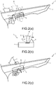
FIG. 2(a) is a front view of a neck of the keytar in a case of operating a ribbon controller;FIG. 2(b) is a cross-sectional view of the neck in a case of loading pressure on the ribbon controller or a case of operating a modulation bar; andFIG. 2(c) is a front view of the neck in a case of operating the modulation bar. -
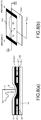
FIG. 3(a) is a cross-sectional view showing the ribbon controller; andFIG. 3(b) is a plan view of a terminal portion in the ribbon controller. -
FIG. 4 is a plan view showing an expanded state (a state before a use form is formed) of the ribbon controller. -
FIG. 5 is a cross-sectional view showing the expanded state (the state before a use form is formed) of the ribbon controller. -
FIG. 6(a)-FIG. 6(f) are illustration diagrams for illustrating a manufacturing method of the ribbon controller. -
FIG. 7 is a circuit diagram showing schematic circuit configurations of a pressure sensitive sensor and a position sensor. -
FIG. 8(a) is a cross-sectional view for illustrating an action of the position sensor; andFIG. 8(b) is an illustration diagram for illustrating a detection principle. -
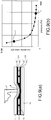
FIG. 9(a) is a cross-sectional view for illustrating an action of the pressure sensitive sensor; andFIG. 9(b) is an illustration diagram showing an example of a resistance-load (pressure) characteristic in the pressure sensitive sensor. -
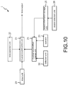
FIG. 10 is a functional block diagram of the keytar. -
FIG. 11 is a block diagram showing an electrical configuration of the keytar. -
FIG. 12(a) is a diagram schematically showing an X-direction aspect information table;FIG. 12(b) is a diagram schematically showing aspect information stored in the X-direction aspect information table;FIG. 12(c) is a diagram schematically showing a YZ-direction aspect information table; andFIG. 12(d) is a diagram schematically showing aspect information stored in the YZ-direction aspect information table. -
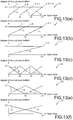
FIG. 13(a)-FIG. 13(f) are graphs respectively showing an aspect of a change of the degree of a musical sound effect. -
FIG. 14 is a flow chart of main processing. -
FIG. 15 is a flow chart of a musical sound generation process. - In the following, preferred examples are described with reference to the attached diagrams.
FIG. 1 is an external view of akeytar 1 that is an embodiment. Thekeytar 1 is an electronic musical instrument, which applies a musical sound effect such as a volume change or a pitch change, a cut-off or a resonance to each of a plurality of tones that is based on a performance operation of a performer H and outputs the tone. Ther term "keytar" refers to an electronic keyboard or synthesizer that can be operated in a performance style like a guitar by hanging it on the neck or shoulder using a strap or the like. Especially in Japan, it is sometimes called "shoulder keyboard". - As shown in
FIG. 1 , akeyboard 2 and settingkeys 3 which change various setting contents of thekeytar 1 are arranged on thekeytar 1. Thekeyboard 2 is an input device for acquiring performance information of a performance of the performer H and is equipped with a plurality ofkeys 2a. The performance information of a MIDI (Musical Instrument Digital Inteface) standard corresponding to a plurality of tones according to a key pressing/key releasing operation of thekeys 2a done by the performer H is output to a CPU 10 (seeFIG. 11 ). Thesetting keys 3 are keys which change various settings of thekeytar 1, for example, tones assigned to thekeys 2a, musical sound effects assigned to aribbon controller 5 and amodulation bar 6 described later inFIG. 2(a)-FIG. 2(c) , or the like. - In a position adjacent to the
keyboard 2, aneck 4 which becomes a handle of the performer H in thekeytar 1 is formed. By grasping theneck 4 with a hand (the left hand of the performer H inFIG. 1 ) that does not operate thekeyboard 2 in the performer H, a balance of thekeytar 1 during the operation of thekeyboard 2 can be stabilized. In addition, the degrees of the musical sound effects with respect to a plurality of tones in output can be changed by theribbon controller 5 and themodulation bar 6 arranged in theneck 4, and the details are described later inFIG. 2(a)-FIG. 2(c) . - Next, the
ribbon controller 5 and themodulation bar 6 arranged in theneck 4 are described with reference toFIG. 2(a)-FIG. 2(c) to FIG. 9(a)-FIG. 9(b) .FIG. 2(a) is a front view of theneck 4 of thekeytar 1 in a case of operating theribbon controller 5;FIG. 2(b) is a cross-sectional view of theneck 4 in a case of loading pressure on theribbon controller 5 or a case of operating themodulation bar 6; andFIG. 2(c) is a front view of theneck 4 in a case of operating themodulation bar 6. - As shown in
FIG. 2(a)-FIG. 2(c) , the ribbon controller (hereinafter abbreviated as "ribbon") 5 and the modulation bar (hereinafter abbreviated as "operation bar") 6 are arranged in theneck 4. Theribbon 5 is a senor having a rectangular shape in a top view in which a position sensor and a pressure sensitive sensor are laminated. Afront surface panel 81 which is a detection surface of theribbon 5 is arranged in an upper portion of the position sensor and the pressure sensitive sensor in theribbon 5, a position of the longitudinal side on thefront surface panel 81 is detected by the position sensor, and a pressing force on thefront surface panel 81 is detected by the pressure sensitive sensor; the details are described later inFIG. 3(a)-FIG. 3(b) to FIG. 9(a)-FIG. 9(b) . In the following, the longitudinal direction of thefront surface panel 81 is referred to as "X-direction" (FIG. 2(a) ), and the direction in which the pressing force is loaded on thefront surface panel 81 is referred to as "Z-direction" (FIG. 2(b) ). That is, two different types of values of the position in the X-direction and the pressing force in the Z-direction can be acquired by oneribbon 5. Herein, a structure of theribbon 5 is described with reference toFIG. 3(a)-FIG. 3(b) to FIG. 9(a)-FIG. 9(b) . -
FIG. 3(a) is a cross-sectional view showing theribbon 5; andFIG. 3(b) is a plan view of a terminal portion in theribbon 5. - The
ribbon 5 has a structure in which the position sensor and the pressure sensitive sensor are formed in a part of a folded sheet (a film) 51. In this embodiment,resistance membranes membranes - The
film 51 includes four parts (a first part, a second part, a third part, and a fourth part). In a state that thefilm 51 is folded, the four parts are laminated. - As described hereinafter, a surface on which the
resistance membrane 52A in the first part (corresponding to apart 51A shown inFIG. 4 ) of thefilm 51 is formed and a surface on which theresistance membrane 52B in the second part (corresponding to apart 51B shown inFIG. 4 ) of thefilm 51 is formed are adhered by a pressure sensitive adhesive (a printing paste) 59. A surface on which themembrane 53A in the third part (corresponding to apart 51C shown inFIG. 4 ) of thefilm 51 is formed and a surface on which themembrane 53B in the fourth part (corresponding to apart 51D shown inFIG. 4 ) of thefilm 51 is formed are also adhered by the pressuresensitive adhesive 59. Besides, in each part, the surface on which theresistance membranes membranes resistance membranes membranes - The rear surface of the second part and the rear surface of the third part are adhered by a double-face tape (a double-face adhesive tape). In regard to the double-face tape, an adhesive 60 is laminated on a front surface and a rear surface of a support (a setting plate) 54. Besides, in
FIG. 3(a) , a separating member (a separator) 55 of the double-face tape of the rear side of the third part is also shown. - A
terminal portion 57 is formed at one end of the film 51 (seeFIG. 3(b) ). Areinforcement plate 56 is pasted on the rear side of theterminal portion 57 in thefilm 51. There is anextension portion 58 between a part in which thereinforcement plate 56 and theterminal portion 57 are formed and a part in which the position sensor and the pressure sensitive sensor are formed. - As shown in
FIG. 3(b) , theterminal portion 57 includes four terminals (1)-(4). In each of the terminals (1)-(4), a pressuresensitive ink 57a is superimposed and formed on asilver layer 57b. Each of the terminals (1)-(4) is electrically connected to one or more of theresistance membranes membranes - The
ribbon 5 has afront surface panel 81. Thefront surface panel 81 is adhered to thelaminated film 51 by an adhesive (for example, the double-face tape).FIG. 3(a) shows an example of using, as the adhesive, the double-face tape in which anadhesive compound 83 is laminated on a front surface and a rear surface of asupport 82. Thefront surface panel 81 is a member for a finger of the performer H or the like to contact and uses, for example, polycarbonate (PC) sheet such as CARBOGLASS (registered trademark) as a material. However, the material of thefront surface panel 81 is not limited to PC sheet. -
FIG. 4 is a plan view showing theribbon 5 before a use form (a folded state) is formed. As shown inFIG. 4 , thefilm 51 includes fourparts - The
resistance membrane 52A (seeFIG. 3(a) ) is formed in a part of the front surface of thepart 51A closest to theextension portion 58. Theresistance membrane 52B (seeFIG. 3(a) ) is formed in a part of the front surface of the part (the part on the right inFIG. 4 ) 51B adjacent to thepart 51A in a P-direction (a longitudinal direction). Themembrane 53B (seeFIG. 3(a) ) made of pressure sensitive ink is formed in a part of the front surface of another part (the upper part inFIG. 4 ) 51D adjacent to thepart 51A in a Q-direction (a width direction). Themembrane 53A (seeFIG. 3(a) ) made of pressure sensitive ink is formed in a part of the front surface of thepart 51C adjacent to thepart 51D in the Q-direction. Besides, in the embodiment, the plane shapes of theresistance membranes membranes - In addition, the
part 51A and thepart 51B can also be seen as being adjacent via a boundary in the width direction (the Q-direction). Thepart 51A and thepart 51D can also be seen as being adjacent via a boundary in the longitudinal direction (the P-direction). Thepart 51D and thepart 51C can also be seen as being adjacent via the boundary in the longitudinal direction (the P-direction). - In addition, in
FIG. 4 , a line segment between the parts indicates the boundary of the parts. An ellipse on the boundary of thepart 51A and thepart 51D and an ellipse on the boundary of thepart 51C and thepart 51D are holes. - The
part 51B in theribbon 5 shown inFIG. 4 before a use form is formed is folded with respect to thepart 51A, and thepart 51C is folded with respect to thepart 51D and further folded with respect to thepart 51A; after that, theribbon 5 includes thepart 51A in which theresistance membrane 52A for position detection is formed, thepart 51B which is located below thepart 51A and in which theresistance membrane 52B for position detection is formed, thepart 51C which is located below thepart 51B and in which the resistance membrane being pressure sensitive (themembrane 53A) is formed, and thepart 51D which is located below thepart 51C and in which the resistance membrane being pressure sensitive (themembrane 53B) is formed. Besides, theparts film 51 in the embodiment). Then, for example, the parts are preferably formed by folding one base material. In addition, in the embodiment, "below the part" refers to a lower portion in a position relationship when the position of thefront surface panel 81 is regarded as an upper portion. -
FIG. 5 is a cross-sectional view showing theribbon 5 before a use form is formed. Besides, inFIG. 5 , cross sections of theparts resistance membranes FIG. 4 are formed are shown. Accordingly, inFIG. 5 , the pressuresensitive adhesive 59 exists on the upper surface side of thefilm 51. Besides, in the example shown inFIG. 5 , aseparator 71 is arranged on the upper surface side of the pressuresensitive adhesive 59. In addition, a condition is shown in which the double-face tape including theseparator 72 and the adhesive 73 is pasted on the lower surface of a part (specifically, thepart 51A) of thefilm 51. - Next, a formation method of the
film 51 is described with reference toFIG. 6(a)-FIG. 6(f) . -
FIG. 6(a)-FIG. 6(f) are illustration diagrams for illustrating a manufacturing method of theribbon 5. Firstly, a plan film which includes fourparts film 51 constituting the expandedribbon 5 and the extension portion 58 (seeFIG. 4 ) is prepared. Besides, the plan film may be a large-area film which includes thefilm 51 constituting a plurality ofribbons 5. Besides, thefilm 51 may be polyimide (PI), polyester terephthalate (PET), polyethylene naphthalate (PEN) and the like. - Next, as shown in
FIG. 6(a) , silver is printed (for example, screen printing) to places (seeFIG. 4 ) in which theresistance membrane 52A and themembranes terminal portion 57 is formed, and asilver layer 91 is formed. Furthermore, as shown inFIG. 6(b) , a conductive carbon (hereinafter referred to as carbon) 92 is printed (for example, screen printing) to places in theparts FIG. 4 ) in which theresistance membranes carbon 92 is also printed to predetermined places in the drawing line. The predetermined places are places in which theparts part 51B, thecarbon 92 is printed onto the place in which the silver is printed so as to protect thesilver layer 91. - In addition, as shown in
FIG. 6(c) , the pressuresensitive ink 93 is printed (for example, screen printing) to predetermined places of theparts FIG. 4 ) in which themembranes - Furthermore, as shown in
FIG. 6(d) , a resistink 94 is printed (for example, screen printing) to a place other than specified places. Besides, the specified places are the places in theparts resistance membranes parts membranes terminal portion 57 is also included in the specified places. - In addition, as shown in
FIG. 6(e) , by printing (for example, screen printing) a UV curable resin in which spacer particles are dispersed onto the places in theparts FIG. 4 ) in which theresistance membrane 52A and themembrane 53B are formed, aspacer dots 95 are formed. - In addition, as shown in
FIG. 6(f) , the pressuresensitive adhesive 59 is printed (for example, screen printing) to a place other than the places in theparts FIG. 4 ) in which theresistance membrane 52B and themembrane 53B are formed. Next, theseparator 71 is arranged on the upper surface side of the pressure sensitive adhesive 59 (seeFIG. 5 ). Besides, to simplify the operation, theseparator 71 may also be arranged on the upper surface sides of all theparts - After that, the double-face tape is pasted on the rear surfaces of the
parts part 51C is used for adhesion with the rear surface of thepart 51B. The double-face tape on the rear surface of thepart 51D is used for adhesion between theribbon 5 and other members. In addition, thereinforcement plate 56 is pasted on the rear surface of theterminal portion 57. Then, punching processing is performed to obtain thefilm 51 in the shape shown inFIG. 4 or the like. - Furthermore, the
parts FIG. 4 to FIG. 6(a)-FIG. 6(f) . - Firstly, the
part 51C is bent toward thepart 51D side so that a boundary of thepart 51C and thepart 51D is creased and themembranes part 51B is bent toward thepart 51A side so that a boundary of thepart 51A and thepart 51B is creased and theresistance membranes - After that, the
parts FIG. 4 . In this state, there are creases between the parts. - In this state, the separator 71 (see
FIG. 5 ) on the front surface of thepart 51D is peeled. When theseparator 71 is arranged in all theparts separators 71 on the front surfaces of theparts part 51C is folded again toward thepart 51D side so that themembranes sensitive adhesive 59 is formed on the front surface of thepart 51D (seeFIG. 6(f) ), the front surface of thepart 51C and the front surface of thepart 51D are adhered. - Next, the separator 71 (see
FIG. 5 ) on the front surface of thepart 51B is peeled. Then, thepart 51B is folded again toward thepart 51A so that theresistance membranes sensitive adhesive 59 is formed on the front surface of thepart 51B (seeFIG. 6(f) ), the front surface of thepart 51A and the front surface of thepart 51B are adhered. - In addition, the
separator 72 of the double-face tape pasted on the rear surface of thepart 51C is peeled. Besides, in this state, thepart 51B is folded toward thepart 51A side, and thepart 51C is folded toward thepart 51D side. Then, the rear surface of thepart 51C and the rear surface of thepart 51B are adhered by the double-face tape. - Furthermore, the double-face tape is pasted on the rear surface of the
front surface panel 81, and thefront surface panel 81 and thepart 51A of thefilm 51 are adhered by the double-face tape. - In this way, the
ribbon 5 shown inFIG. 3(a)-FIG. 3(b) is obtained. - Besides, the processes for bending or folding the four parts (the first part, the second part, the third part, and the fourth part) may be carried out manually or a jig for carrying out the processes may be used.
- Next, actions of the position sensor formed on the
parts film 51 and the pressure sensitive sensor formed on theparts film 51 are described with reference toFIG. 7 to FIG. 9(a)-FIG. 9(b) .FIG. 7 is a circuit diagram showing schematic circuit configurations of the pressure sensitive sensor and the position sensor. Besides, terminals (1)-(4) inFIG. 7 correspond to the terminals (1)-(4) inFIG. 3(b) . -
FIG. 8(a) is a cross-sectional view for illustrating an action of the position sensor in theribbon 5.FIG. 8(b) is an illustration diagram for illustrating a detection principle. - The
film 51 is shown in two places ofFIG. 8(a) , and theupper film 51 corresponds to thepart 51A (seeFIG. 4 and the like), and thelower film 51 corresponds to thepart 51B (seeFIG. 4 and the like). In addition, thecarbon 92 on the upper side corresponds to theresistance membrane 52A (seeFIG. 3(a)-FIG. 3(b) and the like), and thecarbon 92 and thesilver layer 91 on the lower side correspond to theresistance membrane 52B (seeFIG. 3(a)-FIG. 3(b) and the like). Besides, inFIG. 8(a) , thespacer dots 95 and thespacer 97 are also shown. The part of thespacer 97 includes the pressure sensitive adhesive 59 or the resistink 94. - As shown in
FIG. 8(b) , a power-supply voltage (Vcc) and a ground potential (0 V) are supplied to two sides (black parts inFIG. 8(b) ) of theresistance membrane 52A. Besides, the power-supply voltage (Vcc) and the ground potential (0 V) are supplied from the terminal (3) and the terminal (2) inFIG. 7 . However, the ground potential (0 V) may also be supplied from the terminal (3), and the power-supply voltage (Vcc) may also be supplied from the terminal (2). The place in which the Vcc is supplied is set as a power-supply electrode, and the place in which 0 V is supplied is set as a ground electrode. An output (Vout) is extracted from the drawing line connected to theresistance membrane 52B. Besides, the output is extracted from the terminal (4) inFIG. 7 . - The direction orthogonal to the two sides of the
resistance membrane 52A is set as a p-direction. As shown inFIG. 8(a) , the finger of the performer H or the like comes into contact with theribbon 5. R1 represents a resistance value between the power-supply voltage and a place E in contact with the finger of the performer H or the like. R2 represents a resistance value between the place in contact with the finger of the performer H or the like and the ground electrode. - The ratio of a distance from the place E to the electrodes on two ends is equivalent to the ratio of the resistance values of R1 and R2. Thus, when the
resistance membrane 52A comes into contact with theresistance membrane 52B due to the contact of the finger of the performer H or the like in the place E, a voltage corresponding to the position of the p-direction appears as the Vout. -
FIG. 9(a) is a cross-sectional view for illustrating an action of the pressure sensitive sensor.FIG. 9(b) is an illustration diagram showing an example of a resistance-load (pressure) characteristic in the pressure sensitive sensor. - The
film 51 is shown in two places ofFIG. 9(a) , thefilm 51 on the upper side corresponds to thepart 51C (seeFIG. 4 and the like), and thefilm 51 on the lower side corresponds to thepart 51D (seeFIG. 4 and the like). In addition, thesilver layer 91 and the pressuresensitive ink 93 on the upper side correspond to themembrane 53A (seeFIG. 3(a)-FIG. 3(b) and the like), and the pressuresensitive ink 93 and thesilver layer 91 on the lower side correspond to themembrane 53B (seeFIG. 3(a)-FIG. 3(b) and the like). Besides, inFIG. 9(a) , thespacer dots 95 and thespacer 97 are also shown. The part of thespacer 97 includes the pressure sensitive adhesive 59 or the resistink 94. - As shown in
FIG. 9(a) , the finger of the performer H or the like comes into contact with theribbon 5 in the place E. If the pressing force of the finger of the performer H or the like is large when themembrane 53A and themembrane 53B become a conductive state due to the contact of the finger of the performer H or the like, a contact area of themembrane 53A and themembrane 53B increases and a conductive resistance value is reduced. For example, the ground potential is supplied from the terminal (2) inFIG. 7 to thepart 51C, and the output is extracted from the drawing line connected to themembrane 53B. Besides, the output is extracted from the terminal (1) inFIG. 7 . - As shown by the resistance-load (pressure) characteristic shown in
FIG. 9(b) , the magnitude of the pressing force is expressed as the magnitude of the resistance value. InFIG. 9(b) , a black circle F indicates that the pressing force is large and the resistance value detected as the output is small, and a black circle G indicates that the pressing force is small and the resistance value detected as the output is large. - As described above, the
ribbon 5 of the embodiment can detect the contact position of the finger of the performer H or the like, namely the detecting position, by the position sensor and can detect the pressing force of the finger of the performer H or the like by the pressure sensitive sensor. - In addition, in the ribbon 5 of the disclosure, one base material (for example, the film 51) includes four parts (the first part, the second part, the third part, and the fourth part, which are, for example, the part 51A, the part 51B, the part 51C, and the part 51D), resistance membranes for position detection (for example, the resistance membranes 52A, 52B) are formed on each of the first part (for example, the part 51) and the second part (for example, the part 51B) which are two adjacent parts in the four parts, and resistance membranes being pressure sensitive (for example, the membranes 53A, 53B made of the pressure sensitive ink 93) are formed in each of the third part (for example, the part 51C) and the fourth part (for example, the part 51D) which are the other two adjacent parts of the four parts; the second part is laminated by being folded with respect to the first part, the third part is laminated by being folded with respect to the fourth part, and the two parts (for example, a laminate of the parts 51A,51B and a laminate of the parts 51C, 51D) formed by folding are interfolded; due to this structure, the amount of components of the ribbon 5 is reduced compared with a case in which the position sensor and the pressure sensitive sensor are separately fabricated. As a result, the
ribbon 5 can be manufactured inexpensively. In addition, because one base material is folded and manufactured, assembling of theribbon 5 becomes simple. For example, when the position sensor and the pressure sensitive sensor are fabricated separately, alignment in high accuracy is required when the position sensor and the pressure sensitive sensor are integrated; in comparison, the alignment is relatively easy in theribbon 5 of the disclosure. Furthermore, because the position sensor and the pressure sensitive sensor are formed in one member (the film 51), theterminal portion 57 can be aggregated and arranged on the same plane. - In addition, the position sensor and the pressure sensitive sensor can be approapriately applied, by being used in combination, to an electronic musical instrument capable of controlling the strength of sound corresponding to a contact degree of the finger of the performer H or the like.
- In addition, in the embodiment, the
ribbon 5 is also disclosed which is configured in a manner that in the state before the respective parts are folded, the second part (for example, thepart 51B) is adjacent to the first part (for example, thepart 51A) in the longitudinal direction of the first part, the fourth part (for example, thepart 51D) is adjacent to the first part in the width direction (the direction orthogonal to the longitudinal direction) of the first part, and the third part is adjacent to the fourth part in the longitudinal direction of the fourth part. - In addition, in the embodiment, the
ribbon 5 is also disclosed in which the resistance membrane for position detection made of carbon or made of silver and carbon is formed on the first part (for example, thepart 51A) and the second part (for example, thepart 51B) by screen printing, and the resistance membrane being pressure sensitive made of silver and pressure sensitive ink is formed on the third part (for example, thepart 51C) and the fourth part (for example, thepart 51D) by screen printing. - In addition, in the embodiment, the
ribbon 5 is also disclosed in which the front surface of the first part (for example, thepart 51A) and the front surface of the second part (for example, thepart 51B) are adhered by the pressure sensitive adhesive, the front surface of the third part (for example, thepart 51C) and the front surface of the fourth part (for example, thepart 51D) are adhered by the pressure sensitive adhesive, and the rear surface of the second part and the rear surface of the third part are adhered by the double-face adhesive tape. - Return to
FIG. 2(a)-FIG. 2(c) . Near theribbon 5, that is, in the position adjacent to theribbon 5, anoperation bar 6 is arranged. Theoperation bar 6 is an operator which is arranged along the longitudinal side of theribbon 5 and outputs an operation amount by operating to recline theoperation bar 6 toward the opposite side of theribbon 5. In the following, the direction of operating theoperation bar 6 is referred to as "Y-direction" (FIG. 2(b), FIG. 2(c) ). - Different types of musical sound effects are respectively assigned to the detection positions in the X-direction and the pressing force in the Z-direction detected by the
ribbon 5 and the operation amount in the Y-direction detected by theoperation bar 6, and the degrees of the musical sound effects are respectively set corresponding to the detection positions in the X-direction, the pressing force in the Z-direction or the operation amount in the Y-direction; the details are described later. - In a conventional keytar, the keyboard and the ribbon controller capable of detecting only the detection positions of the X-direction are also arranged; the performer H performs, on the keytar, a sound instruction by an operation of the right hand on the keyboard and controls the musical sound effect corresponding to the position of the ribbon controller specified by the left hand, and thereby put on a performance as if playing on a guitar. However, since the ribbon controller of the keytar is capable of detecting only the detection positions in the X-direction, the ribbon controller of the keytar cannot change the degree of the musical sound effect even if a pressing force is applied to the ribbon controller in the manner of changing a force of the finger pressing down a guitar string or of strongly pressing the guitar string in a flapping manner with the finger.
- On the contrary, in the
ribbon 5 of thekeytar 1 in the embodiment, a pressing force in the Z-direction can be detected, and the degree of the musical sound effect corresponding to this pressing force in the Z-direction is set. Accordingly, when the pressing force in the Z-direction is applied to theribbon 5 in the manner of changing the force of the finger pressing down the guitar string or of strongly pressing the guitar string in the flapping manner with the finger, the degree of the musical sound effect can be changed corresponding to the pressing force. That is, the performance of the guitar can be put on more appropriately by thekeytar 1. - In addition, because the
ribbon 5 and theoperation bar 6 are arranged adjacently, three different degrees of musical sound effects can be changed while a hand movement of the performer H is suppressed to the minimum. Furthermore, as shown inFIG. 2(a)-FIG. 2(c) , the X-direction and the Z-direction in theribbon 5 and the Y-direction in theoperation bar 6 are directions orthogonal to each other, and thus the directions for changing the three different types of degrees of musical sound effects, namely, a direction specifying the detection positions in the X-direction, a direction in which the pressing force in the Z-direction is loaded, and a direction indicating the operation amount in the Y-direction are orthogonal to each other. Accordingly, a situation can be prevented in which an undesired type of degree of musical sound effect of the performer H is changed due to operation mistakes of the performer H when setting the three degrees of musical sound effects. - Next, a function of the
keytar 1 is described with reference toFIG. 10. FIG. 10 is a functional block diagram of thekeytar 1. As shown inFIG. 10 , thekeytar 1 has aninput unit 20, a musicalsound control unit 21, adetection unit 22, anoperator 23, a musical soundeffect change unit 24, an aspectinformation storage unit 25, anaspect selection unit 26, and atone selection unit 27. - The
input unit 20 has a function for inputting a sound instruction of a plurality of tones to thekeytar 1 by one input from the performer H and is implemented by the keyboard 2 (thekeys 2a). The musicalsound control unit 21 has a function for applying a musical sound effect to each of the plurality of tones that is based on the sound instruction input from theinput unit 20 and outputting the tones and is implemented by aCPU 11 described later inFIG. 11 . - The
detection unit 22 has a detection surface and has a function for detecting the detection positions on the detection surface and the pressing force loaded on the detection surface, and is implemented by theribbon 5. Theoperator 23 has a function for inputting the operation from the performer H and is implemented by theoperation bar 6. The musical soundeffect change unit 24 has a function for chaning, for each tone, the degree of the musical sound effect applied to each tone by the musicalsound control unit 21 corresponding to the detection positions and the pressing force detected by thedetection unit 22 or the operation of theoperator 23, and is implemented by theCPU 11. In the embodiemnt, different types of musical sound effects are respectively assigned to the detection positions and the pressing force of thedetection unit 22, or the operation amount of theoperator 23 in advance, and the musical soundeffect change unit 24 changes, for each tone, the degrees of the musical sound effects respectively assigned corresponding to the detection positions and the pressing force of thedetection unit 22, or the operation amount of theoperator 23. - The aspect
information storage unit 25 has a function for storing aspect information representing a change of the degree of the musical sound effect applied to each tone correesponding to the detection positions detected by thedetection unit 22, and is implemented by an X-direction aspect information table 11b described later inFIG. 11 andFIG. 12(a) . Theaspect selection unit 26 has a function for selecting the aspect information stored in the aspectinformation storage unit 25 and is implemented by theCPU 11. Thetone selection unit 27 has a function for selecting a plurality of tones which are objects of the sound instruction obtained by one input of theinput unit 20 and is implemented by theCPU 11. - From the above, by the musical
sound control unit 21, a plurality of tones which is selected by thetone selection unit 27 and which is based on the sound instruction obtained by one input of theinput unit 20 is output after the musical sound effects are applied to the plurality of tones. At this time, the musical soundeffect change unit 24 changes, for each tone, the degrees of the musical sound effects respectively assigned corresponding to the detection positions and the pressing force of thedetection unit 22 or the operation amount of theoperator 23. Accordingly, an expressive performance rich in change of the degree of the musical sound effect for each tone can be achieved. - Particularly, the change of the degree of the musical sound effect for each tone corresponding to the detection positions detected by
detection unit 22 is stored in the aspectinformation storage unit 25, and is performed based on the aspect information selected by theaspect selection unit 26. Accordingly, the degree of the musical sound effect can be changed appropriately according to the aspect information suitable for the preference of the performer H or the genre or tune of a song to be played. - Next, an electrical configuration of the
keytar 1 is described with reference toFIG. 11 to FIG. 13(a)-FIG. 13(f) .FIG. 11 is a block diagram showing the electrical configuration of thekeytar 1. Thekeytar 1 has aCPU 10, aflash ROM 11, aRAM 12, akeyboard 2, a settingkey 3, aribbon 5, anoperation bar 6, asound source 13, and a Digital Signal Processor 14 (hereinafter referred to as "DSP 14"), which are respectively connected via abus line 15. A digital analog converter (DAC) 16 is connected to theDSP 14, anamplifier 17 is connected to the DAC16, and aspeaker 18 is connected to theamplifier 17. - The
CPU 10 is an arithmetic device for controlling each portion connected by thebus line 15. Theflash ROM 11 is a rewritable non-volatile memory and is equipped with a control program 11a, an X-direction aspect information table 11b, and a YZ-direction aspect information table 11c. When the control program 11a is excuted by theCPU 10, the main processing ofFIG. 14 is excuted. The X-direction aspect information table 11b is a data table in which the aspect of the change of the degrees of the musical sound effects assigned to the detection positions in the X-direction of theribbon 5 is stored. The X-direction aspect information table 11b is described with reference toFIG. 12(a)-FIG. 12(d) andFIG. 13(a)-FIG. 13(f) . -
FIG. 12(a) is a diagram schemically showing the X-direction aspect information table 11b. In the X-direction aspect information table 11b, the aspect information associated with an aspect level representing an aspect type of the change of the degree of the musical sound effect and associated with each number of the tones which are sound production objects of one key 2a (seeFIG. 1 ) of thekeyboard 2 is stored. In the embodiment, there are at most four tones which are the sound production objects of one key 2a, and thus the aspect information is stored for each of the sound production numbers of two to four which is the number of the tones produced at the same time. The X-direction aspect information table 11b is an example of the aspectinformation storage unit 25 inFIG. 10 . - As shown in
FIG. 12(a) , in anaspect level 1 of the aspect level, aspect information L14 being the aspect information in which the sound production number is four, aspect information L13 being the aspect information in which the sound production number is three, and aspect information L12 being the aspect information in which the sound production number is two are respectively stored in the X-direction aspect information table 11b. Similarly, the aspect information after anaspect level 2 is also stored in the X-direction aspect information table 11b. Herein, with reference toFIG. 12(b) , the aspect information stored in the X-direction aspect information table 11b is described using the aspect information L14 as an example. -
FIG. 12(b) is a diagram schemically showing the aspect information L14 stored in the X-direction aspect information table 11b. The aspect information is data in which the degree of the musical sound effect for each of tone A-tone D which are four tones corresponding to input values based on the detection positions in the X-direction of theribbon 5 is stored. In the aspect information L14, the degree of the musical sound effect for each of the tone A-tone D which are four tones corresponding to the input values based on the detection positions in the X-direction of theribbon 5 is stored. - The input values are values obtained by converting the detection positions in the X-direction detected by the
ribbon 5 into numbers of 0-127. Specifically, in regard to the input value, when the position of one end (for example, the left end in a front view) in the X-direction of thefront surface panel 81 of theribbon 5 inFIG. 2(a) is set as "0" and the position at the other end is set as "127", a distance from the position at one end to the position at the other end on the X-direction side of thefront surface panel 81 is divided into 128 at equal intervals, and each detection position is expressed as an integer of 0-127. That is, values of 0-127 which correspond to the detection positions in the X-direction of thefront surface panel 81 sepecified by the finger of the performer H are acquired as the input values. - The degree of the musical sound effect with respect to the input value is also set to "0" as the minimum value and "127" as the maxmum value, and the degrees are set as integers equally divided into 128. That is, the assigned musical sound effect is not applied when the degree of the musical sound effect is 0, while the musical sound effect is applied to the fullest when the degree of the musical sound effect is 127.
- Then, the degree of the musical sound effect for each of the tone A-tone D corresponding to the input values based on the detection positions in the X-direction of the
front surface panel 81 of theribbon 5 is acquired from the aspect information L14 and applied to the musical sound effect which is assigned to the X-direction of thefront surface panel 81. For example, when the aspect information L14 is specified, "volume" is assigned as a musical sound effect in the X-direction of thefront surface panel 81, and the input value based on the detection position in the X-direction of thefront surface panel 81 is "41", as shown inFIG. 12(b) , the "volume" for tone A is set to "127", the "volume" for tone B is set to "127", the "volume" for tone C is set to "3", and the "volume" for tone D is set to "0". - In the embodiment, the degree of the musical sound effect stored in the aspect information L14 and the like is not applied only to a case when the musical sound effect is the "volume", but applied in common to a setting of the degree of other musical sound effects such as pitch change or resonance, cut-off and the like. Accordingly, it is unnecessary to respectively prepare the aspect information L14 and the like for the types of the musical sound effect and thus memory resource can be saved. In the X-direction aspect information table 11b of
FIG. 12(a) , the aspect information L14 and the like is stored in each aspect level representing the aspect type of the change of the degree of the musical sound effect. Herein, the aspect type of the change of the degree of the musical sound effect is described with reference toFIG. 13(a)-FIG. 13(f) . -
FIG. 13(a)-FIG. 13(f) are graphs respectively showing the aspect of the change of the degree of the musical sound effect. InFIG. 13(a)-FIG. 13(f) , the horizontal axis represents the input values and the vertical axis represents the degrees of the musical sound effects with respect to the input values. -
FIG. 13(a)-FIG. 13(c) respectively show the aspect of the change of the degree of the musical sound effect for the aspect information L14-L12 in theaspect level 1 ofFIG. 12(a) . In the aspect information L14 in which four tones are produced, for the tone A, the degree of the musical sound effect remains the maximum value of 127 across the input value of 0-127; for the tone B, the degree of the musical sound effect is increased by a linear function from 0 to 127 when the input value is 0-40, and the degree of the musical sound effect remains 127 when the input value is 41 or more. For the tone C, the degree of the musical sound effect is 0 when the input value is 0-40 while the degree of the musical sound effect is increased by a linear function from 0 to 127 when the input value is 41-80, and the degree of the musical sound effect remains 127 when the input value is 81 or more. For the tone D, the degree of the musical sound effect is 0 when the input value is 0-80 while the degree of the musical sound effect is increased by a linear function from 0 to 127 when the input value is 81-127. - In the aspect information L14, by changing the degree of the musical sound effect in this way, the musical sound effects assigned to the detection positions in the X-direction are only applied to the tone A when the input value is 0; the musical sound effects assigned to the detection positions in the X-direction are only applied to the tones A, B when the input value is 1-40; the musical sound effects assigned to the detection positions in the X-direction are only applied to the tones A, B, C when the input value is 41-80; and the musical sound effects assigned to the detection positions in the X-direction are applied to all the tones A-D when the input value is 81 or more. Accordingly, according to the detection positions in the X-direction specified by the performer H toward the
front surface panel 81 of theribbon 5, the number of tones A-D to which the musical sound effects assigned to the detection positions in the X-direction are applied can be switched rapidly. - Furthermore, if the performer H continuously specifies by sliding the finger from one end side to the other end side (that is, from the input value of 0 to the the input value of 127) in the X-direction of the
front surface panel 81, the musical sound effect can be applied to overlay the tones A-D in order. In addition, because the degrees of the musical sound effects of the tones A-D are increased by a linear function corresponding to the change of the input value, for at least one of the degrees of the musical sound effects of the tones A-D, the change of this degree of the musical sound effect always rises to the right. Accordingly, any one of the degrees of the musical sound effects of the tones A-D is always increased when the degree of the musical sound effect is continuously changed from one end side to the other end side in the X-direction of thefront surface panel 81. Accordingly, a musical sound rich in dynamic feeling (excitement feeling) obtained by the musical sound effect can be produced. - On the othe hand, if the performer H continuously specifies from the other end side to one end side (that is, from the input value of 127 to the input value of 0) in the X-direction of the
front surface panel 81, the musical sound effects of the tones A-D that are applied can be released in order. Accordingly, by continuously specifying thefront surface panel 81, an expressive performance rich in change of the degrees of the musical sound effects of the tones A-D can be achieved. - In addition, the aspect information L13 shown in
FIG. 13(b) in which three tones are produced or the aspect information L12 shown inFIG. 13(c) in which two tones are produced in thesame aspect level 1 is also changed in the degrees of the musical sound effects with respect to the tones A-C or the tones A, B in accordance with the above-described aspect information L14. Accordingly, in thesame aspect level 1, even if the number of tones which are the sound production objects of one key 2a during performance is decreased from four to three or two, a feeling of strangeness of the performer H or the audience on the change of the degree of the musical sound effect can be suppressed to the minimum. - Next, an
aspect level 2 which is an aspect level different from theaspect level 1 is described with reference toFIG. 13(d)-FIG. 13(f). FIG. 13(d)-FIG. 13(f) respectively show the aspect of the change of the degree of the musical sound effect for the aspect information L24-L22 in theaspect level 2 ofFIG. 12(a) . - As shown in
FIG. 13(d) , in the aspect information L24 in which four tones are produced, for the tone A, the degree of the musical sound effect is decreased by a linear function from 127 to 0 when the input value is 0-40, and the degree of the musical sound effect remains 0 when the input value is 41 or more. For the tone B, the degree of the musical sound effect is increased by a linear function from 0 to 127 when the input value is 0-40, the degree of the musical sound effect is decreased by a linear function from 127 to 0 when the input value is 41-80, and the degree of the musical sound effect remains 0 when the input value is 81 or more. For the tone C, the degree of the musical sound effect remains 0 when the input value is 0-40, the degree of the musical sound effect is increased by a linear function from 0 to 127 when the input value is 41-80, and the degree of the musical sound effect is decreased by a linear function from 127 to 0 when the input value is 80-127. For the tone D, the degree of the musical sound effect remains 0 when the input value is 0-80, and the degree of the musical sound effect is increased by a linear function from 0 to 127 when the input value is 81-127. - In the aspect information L24, by changing the degree of the musical sound effect in this way, when the input values are 0, 40, 80, 127, the degree of the musical sound effect with respect to only one tone within the tones A, B, C, D becomes the maxmum value of 127 and the degrees of the musical sound effects with respect to the other tones become 0. Accordingly, by specifying the detection positions in the X-direction corresponding to the input values of 0, 40, 80, 127, the musical sound effects assigned to the detection positions in the X-direction can be applied to only one tone.
- In addition, the musical sound effects assigned to the detection positions in the X-direction are only applied to the tones A, B when the input value is 1-40; the musical sound effects assigned to the detection positions in the X-direction are applied to the tones B, C when the input value is 41-80; and the musical sound effects assigned to the detection positions in the X-direction are applied to the tones C, D when the input value is 81 or more. That is, the degrees of the musical sound effects with respect to only two tones within the four tones can be set finely.
- In addition, for example, a volume change is set in the tone effect for the detection position in the X direction, a clear guitar sound is set in the tone A, and tones with a strong distortion are set in the tones B-D in the order of tone B→tone C→tone D. If the performer H continuously specifies from one end side to the other end side in the X-direction of the
front surface panel 81, a distortion condition of the produced musical sound can be increased gradually; on the other hand, if the performer H discretely specifies the position in the X-direction of thefront surface panel 81, the musical sound of the distortion condition corresponding to this position can be produced. - In addition, similar to the
aspect level 1, the aspect information L23 shown inFIG. 13(e) in which three tones are produced or the aspect information L22 shown inFIG. 13(f) in which two tones are produced is also changed in the degrees of the musical sound effects with respect to the tones A-C or the tones A, B in accordance with the above-described aspect information L24. - In this way, the aspect information of a plurality of aspect levels is stored in the X-direction aspect information table 11b, and thus an aspect level suitable for the preference of the performer H or the genre or tune of a song to be played can be selected from the plurality of aspect levels, and the degree of the musical sound effect can be changed appropriately. In addition, the change of the degree of the musical sound effect can be switched in various ways by switching the aspect level during performance, and thus an expressive performance can be achieved.
- Return to
FIG. 11 . The YZ-direction aspect information table 11c is a data table in which the change aspect of the degree of the musical sound effect assigned to the operation amount in the Y-direction of theoperation bar 6 or the pressing force in the Z-direction of theribbon 5 is stored. The YZ-direction aspect information table 11c is described with reference toFIG. 12(c) and FIG. 12(d) . -
FIG. 12(c) is a diagram schemically showing the YZ-direction aspect information table 11c; andFIG. 12(d) is a diagram schemically showing aspect information L4 stored in the YZ-direction aspect information table 11c. The YZ-direction aspect information table 11c is stored corresponding to the number of tones which are the sound production objects of one key 2a of thekeyboard 2, the aspect information L4 is stored as the aspect information with a sound production number of four in the YZ-direction aspect information table 11c; similarly, aspect information L3 is stored as the aspect information with a sound production number of three and aspect information L2 is stored as the aspect information with a sound production number of two in the YZ-direction aspect information table 11c. Only the aspect information of one aspect level is stored in the YZ-direction aspect information table 11c. - As shown in
FIG. 12(d) , in the aspect information L14, the degree of the musical sound effect with respect to each of the tone A-tone D which are four tones corresponding to the input values based on the operation amount in the Y-direction of theoperation bar 6 or the pressing force in the Z-direction of theribbon 5 is stored. The input values here are also values which are obtained by converting the operation amount in the Y-direction of theoperation bar 6 or the pressing force in the Z-direction of theribbon 5 into 0-127. - In the embodiment, the input value for the operation amount in the Y-direction of the
operation bar 6 is set to "0" in a state that theoperation bar 6 is separated from the performer H, and is set to "127" in a state that theoperation bar 6 is reclined toward theribbon 5 side as much as possible, and thereby the operation amount is expressed as the integers equally divided into 128. In addition, the input value for the pressing force in the Z-direction of theribbon 5 is set to "0" in a state that the pressing force is not loaded, and is set to "127" in a state that the maxmum pressing force that can be detected by theribbon 5 is applied, and thereby the pressing force is expressed as the integers equally divided into 128. - As shown in
FIG. 12(d) , in the aspect information L4, the degrees of the musical sound effects of the tones A-D are increased by a linear function from 0 to 127 with respect to the input values 0-127 according to the operation amount in the Y-direction of theoperation bar 6 or the pressing force in the Z-direction of theribbon 5. In addition, although not shown, the aspect information L3 or the aspect information L2 is also changed in the degrees of the musical sound effects with respect to the tones A-C or the tones A, B in accordance with the above-described aspect information L4. - In this way, in the embodiment, only the aspect information of one aspect level is stored in the YZ-direction aspect information table 11c, and the aspect information is also set as so-called simple aspect information in which the degrees of the musical sound effects of the tones A-D are increased by a linear function with respect to the input values. The reason is that compared with the detection positions in the X-direction of the
front surface panel 81 of theribbon 5, the operation amount in the Y-direction of the operation bar or the pressing force toward the Z-direction of thefront surface panel 81 is hard for the performer H to know how much the operation amount or the pressing force is added; moreover, when the degree of the musical sound effect is changed complicately according to a plurality of aspect information with respect to the operation amount in the Y-direction of theoperation bar 6 or the Z-direction of thefront surface panel 81, it is even harder to know the aspect of this change. - Therefore, by changing the degree of the musical sound effect assigned to the operation amount in the Y-direction of the
operation bar 6 or the pressing force in the Z-direction of theribbon 5 according to one simple aspect information, the performer H easily grasps the change of the degree of the musical sound effect, and thus operability of thekeytar 1 can be improved. On the other hand, if the musical sound effects in which complicate change of the degrees is intended are assigned to the detection positions in the X-direction of theribbon 5, as in the above-described aspect information L14 and the like, the degrees of the musical sound effects with respect to the tones A-D can be changed finely. In addition, by appropriately switching the musical sound effects assigned to the detection positions in the X-direction of theribbon 5, the operation amount in the Y-direction of theoperation bar 6, and the pressing force in the Z-direction of theribbon 5, the change of the degrees of the musical sound effects can be switched flexibly corresponding to the preference of the performer H. - Return to
FIG. 11 . TheRAM 12 is a memory which rewritably stores various work data, flags or the like when theCPU 10 excutes programs such as the control program 11a and the like, and theRAM 12 has an X-directioninput value memory 12a in which the input values converted from the detection positions from thefront surface panel 81 of the above-describedribbon 5 are stored, a Y-directioninput value memory 12b in which the input values converted from the operation amount in the Y-direction of theoperation bar 6 are stored, a Z-directioninput value memory 12c in which the input values converted from the pressing force applied to thefront surface panel 81 are stored, an X-directionaspect information memory 12d in which the aspect information selected from the X-direction aspect information table 11b by the performer H is stored, and a YZ-directionaspect information memory 12e in which the aspect information selected from the YZ-direction aspect information table 11c by the performer H is stored. - The
sound source 13 is a device which outputs waveform data corresponding to performance information input from theCPU 10. TheDSP 14 is an arithmetic device for performing an arithmetic processing on the waveform data input from thesound source 13. TheDAC 16 is a conversion device which converts the waveform data input from theDSP 14 into analog waveform data. Theamplifier 17 is an amplification device which amplifies the analog waveform data output from theDAC 16 with a predetermined gain, and thespeaker 18 is an output device which emits (outputs) the analog waveform data amplified by theamplifier 17 as a musical sound. - Next, main processing excuted by the
CPU 10 is described with reference toFIG. 14 andFIG. 15 .FIG. 14 is a flow chart of the main process. The main processing is excuted at power-up of thekeytar 1. - In the main processing, firstly, a confirmation is made on whether a selection operation of the tone or the aspect level is performed by the setting key 3 (see
FIG. 1 andFIG. 11 ) (S1). Specifically, a confirmation is made on whether the tones with a maximum number of four produced by pressing one key 2a is selected from the tones included in thekeytar 1 or the aspect level is selected by the performer H via the settingkey 3. - When the selection operation of the tones or the aspect level is performed in the processing of S1 (S1: Yes), the aspect information corresponding to the selected number of tones and the selected aspect level is acquired from the X-direction aspect information table 11b and stored in the X-direction
aspect information memory 12d (S2); the aspect information corresponding to the number of tones that is set is acquired from the Y-direction aspect information table 11c and stored in the Y-directionaspect information memory 12e (S3). At this time, the setting on which tone within the selected tones corresponds to the tones A-D is also perfomed at the same time. Besides, theCPU 11 excuting the processing of S1 is an example of thetone selection unit 27 inFIG. 10 , and theCPU 11 excuting the processing of S2 is an example of theaspect selection unit 26 inFIG. 10 . - Then, after the processing of S3, an instruction of tone change is output to the sound source 13 (S4). On the other hand, in the processing of S1, when the selection operation of the tones is not performed (S1: No), the processing of S2-S4 are skipped.
- After the processing of S1 or S4, a confirmation is made on whether the musical sound effects assigned to the detection positions in the X-direction of the
ribbon 5, the operation amount in the Y-direction of theoperation bar 6 or the pressing force in the Z-direction of theribbon 5 are changed by the setting key 3 (S5). When the assigned musical sound effects are changed (S5: Yes), mutually different musical sound effects are respectively assigned to the detection positions in the X-direction of theribbon 5, the operation amount in the Y-direction of theoperation bar 6 or the pressing force in the Z-direction of the ribbon 5 (S6). Accordingly, it can be prevented that the same type of musical tone effect is assigned to the detection positions in the X-direction of theribbon 5, the operation amount in the Y-direction of theoperation bar 6 or the pressing force in the Z-direction of theribbon 5, and thus a feeling of strangeness on the performance of thekeytar 1 can be suppressed. On the other hand, in the processing of S5, when the assigned musical sound effects are not changed (S5: No), the processing of S6 is skipped. - After the processing of S5 or S6, the detection positions in the X-direction of the
ribbon 5 are acquired, and the detection positions in the X-direction converted into the input values are stored in the X-directioninput value memory 12a (S7); the operation amount in the Y-direction of theoperation bar 6 is acquired, and the operation amount in the Y-direction converted into the input values is stored in the Y-directioninput value memory 12b (S8); the pressing force in the Z-direction from theribbon 5 is acquired, and the pressing force in the Z-direction converted into the input values is stored in the Z-directioninput value memory 12c (S9). - After the processing of S9, musical sound generation processing is excuted (S10). Herein, the musical sound generation processing is described with reference to
FIG. 15 . -
FIG. 15 is a flow chart of the musical sound generation processing. In the musical sound generation processing, firstly, a confirmation is made on whether thekeys 2a of the keyboard are turned on (S11). Specifically, a confirmation is made on whether all thekeys 2a of thekeyboard 2 are turned on one by one. In the following processing S12 to S18, sound production, sound-deadening or change processing of the degree of the musical sound effect for one key 2a is also performed. - When the
keys 2a of thekeyboard 2 are turned on in the processing of S11 (S11: Yes), a confirmation is made on whether thekeys 2a of thekeyboard 2 are changed from turn-off to turn-on (S12). Specifically, a confirmation is made on whether the same key 2a which is off in the last musical sound generation processing is turned on in the present musical sound generation processing. - When the
keys 2a of thekeyboard 2 are changed from turn-off to turn-on (S12: Yes), an instruction for producing the tones selected in the processing of S1 and S4 ofFIG. 14 according to pitches corresponding to thekeys 2a is performed on the sound source 13 (S13). At this time, the musical sound effects assigned to the detection position in the X-direction of theribbon 5, the operation amount in the Y-direction of theoperation bar 6, and the pressing force in the Z-direction of theribbon 5 are also applied to the tones and are output. TheCPU 11 excuting the processing of S13 is an example of the musicalsound control unit 21 inFIG. 10 . On the other hand, when thekeys 2a of the keyboard are not changed from turn-off to turn-on, the corresponding sound production instruction of thekeys 2a is already output and thus the processing of S13 is skipped. - After the processing of S12 or S13, the degrees of respective musical sound effects assigned to the detection positions in the X-direction of the
ribbon 5, the operation amount in the Y-direction of theoperation bar 6, and the pressing force in the Z-direction of theribbon 5 are changed. Specifically, after the processing of S12 or S13, the degrees of the musical sound effects of respective tones in the aspect information of the X-directionaspect information memory 12d corresponding to the input values stored in the X-directioninput value memory 12a are acquired, and are respectively applied to the degrees of the musical sound effects assigned to the detection positions in the X-direction of the ribbon 5 (S14). TheCPU 11 excuting the processing of S14 is an example of the musical soundeffect change unit 24 inFIG. 10 . - After the processing of S14, the degrees of the musical sound effects of respective tones in the aspect information of the YZ-direction
aspect information memory 12d corresponding to the input values for the operation amount in the Y-direction of theoperation bar 6 are acquired, and are respectively applied to the degree of the musical sound effect assigned to the operation amount in the Y-direction of the operation bar 6 (S15); the degrees of the musical sound effects of respective tones in the aspect information of the YZ-directionaspect information memory 12d corresponding to the input values for the pressing force in the Z-direction of theribbon 5 are acquired, and are respectively applied to the degree of the musical sound effect assigned to the pressing force in the Z-direction of the ribbon 5 (S16). - That is, by the processing of S14-S16, the degrees of the musical sound effects assigned to the detection positions in the X-direction of the
ribbon 5, the operation amount in the Y-direction of theoperation bar 6 and the pressing force in the Z-direction of theribbon 5 can be changed based on the input value which is based on each detection position, the operation amount in the Y-direction, and the pressing force. Particularly, in the musical sound effects assigned to the detection positions in the X-direction of theribbon 5, as described above inFIG. 13(a)-FIG. 13(f) , the aspect information of a plurality of aspect levels can be applied. Accordingly, the change of the degrees of the musical sound effects assigned to the detection positions in the X-direction of theribbon 5 can be switched in various ways by appropriately switching the aspect levels during performance, and thus an expressive performance in which the monotony of the degree of the musical sound effect is suppressed can be achieved. - When the
keys 2a of the keyboard are turned off in the processing of S11 (S11: No), a confirmation is made on whether thekeys 2a of thekeyboard 2 are changed from turn-on to turn-off (S17). Specifically, a confirmation is made on whether the same key 2a which is on in the last musical sound generation processing is turned off in the present musical sound generation processing. - When the
keys 2a of thekeyboard 2 are changed from turn-on to turn-off (S17: Yes), an instruction for sound-deadening the tones corresponding to thekeys 2a is performed on the sound source 13 (S18). On the other hand, when thekeys 2a of thekeyboard 2 are not changed from turn-on to turn-off, the corresponding sound-deadening instruction of thekeys 2a is already output and thus the processing of S18 is skipped. - After the processing of S16-S18, a confirmation is made on whether the processing of S11-S18 is completely performed on all the
keys 2a of the keyboard 2 (S19); when the processing is not completed, the processing of S11-S18 is peformed on thekeys 2a other than thekeys 2a on which the processing of S11-S18 are already performed. On the other hand, when the processing of S11-S18 is completely performed on all thekeys 2a of the keyboard 2 (S19: Yes), the musical sound generation processing is ended, and the processing returns to the main processinging ofFIG. 14 . - Return to
FIG. 14 . After the musical sound generation processing of S10 is ended, the processing after S1 is repeated. - A description is given above based on the above-described embodiments, but it can be easily inferred that various improvements and changes can be made.
- In the above-described embodiments, the
keytar 1 is illustrated as the electronic musical instrument. However, the disclosure is not limited hereto and may be applied to other electronic musical instruments such as an electronic organ, an electronic piano or the like in which a plurality of musical sound effects are applied to the tones that are produced. In this case, it is sufficient if theribbon 5 and theoperation bar 6 are arranged on the electronic musical instrument. - In the above-described embodiments, according to the aspect information stored in the X-direction aspect information table 11b and the YZ-direction aspect information table 11c, the degrees of all the musical sound effects are changed. However, the disclosure is not limited hereto, and the degrees of the musical sound effects may be changed according to different aspect information in the musical sound effects. In this case, the X-direction aspect information table 11b and the YZ-direction aspect information table 11c may be arranged for each musical sound effect, and the aspect information corresponding to the musical sound effects assigned to the detection positions in the X-direction, the operation amount in the Y-direction or the pressing force in the Z-direction is acquired from each of the X-direction aspect information table 11b and YZ-direction aspect information table 11c.
- In the above-described embodiments, one musical sound effect is assigned to the detection positions in the X-direction of the
ribbon 5 in the processing of S6 inFIG. 14 ; by the processing of S14 inFIG. 15 , the degrees of the musical sound effects of the respective tones A-D in the aspect information of the X-directionaspect information memory 12d are acquired, and are respectively applied to the degrees of the musical sound effects assigned to the detection positions in the X-direction of theribbon 5. However, the disclosure is not limited hereto, and a plurality of musical sound effects may be assigned to the detection positions in the X-direction of theribbon 5, furthermore, the musical sound effect applied to each of the tones A-D may be assigned from the plurality of musical sound effects, and the degrees of the musical sound effects of the respective tones A-D in the aspect information of the X-directionaspect information memory 12d may be acquired and respectively applied to the degrees of the musical sound effects assigned to the tones A-D. - For example, the musical sound effects of volume change, pitch change, cut-off, and resonance may be respectively assigned to the detection positions in the X-direction of the
ribbon 5; furthermore, from the musical sound effects, the volume change may be assigned to the tone A, the pitch change may be assigned to the tone B, the cut-off may be assigned to the tone C, and the resonance may be assigned to the tone D to acquire the degree of the musical sound effect of each of the tones A-D in the aspect information of the X-directionaspect information memory 12d and apply the acquired degree of the musical sound effect with respect to the tone A to the degree of the volume change assigned to the tone A, and the degrees of the musical sound effects with respect to the tones B-D acquired similarly are applied to the respective degrees of the pitch change, the cut-off, and the resonance assigned to the tones B-D. - With this configuration, the degrees of the plurality of musical sound effects assigned to the respective tones A-D can be changed corresponding to the detection positions in the X-direction of the
ribbon 5, and thus a performance having a high degree of freedom can be achieved. In addition, because the degrees of the plurality of musical sound effects are changed according to the same aspect information, the degrees of the plurality of musical sound effects are respectively changed in a similar aspect corresponding to the detection positions in the X-direction of theribbon 5. Accordingly, an expressive performance which gives regularity to the changes of the plurality of different musical sound effects can be achieved. - In the above-described embodiments, in the processing of S6 in
FIG. 14 , mutually different musical sound effects are respectively assigned to the detection positions in the X-direction of theribbon 5, the operation amount in the Y-direction of theoperation bar 6 or the pressing force in the Z-direction of theribbon 5. However, the disclosure is not limited hereto, and the same musical sound effect may be assigned to all of the detection positions in the X-direction of theribbon 5, the operation amount in the Y-direction of theoperation bar 6, and the pressing force in the Z-direction of theribbon 5. In addition, the same musical sound effect may be assigned to the detection positions in the X-direction of theribbon 5 and the operation amount in the Y-direction of theoperation bar 6, and a different musical sound effect may be assigned to the pressing force in the Z-direction of theribbon 5; alternatively, the same musical sound effect may be assigned to the detection positions in the X-direction of theribbon 5 and the pressing force in the Z-direction of theribbon 5, and a different musical sound effect may be assigned to the operation amount in the Y-direction of theoperation bar 6; alternatively, the same musical sound effect may be assigned to the operation amount in the Y-direction of theoperation bar 6 and the pressing force in the Z-direction of theribbon 5, and a different musical sound effect may be assigned to the detection positions in the X-direction of theribbon 5. - For example, the pitch changes are assigned to the musical sound effects of the detection positions in the X-direction of the
ribbon 5 and the operation amount in the Y-direction of theoperation bar 6, and the resonance is assigned to the musical sound effect of the pressing force in the Z-direction of theribbon 5. Then, the performer H can achieve a performance in which after theoperation bar 6 is operated with the index finger of the left hand to change the pitch continuously, the pitch is changed discretely by specifying the positions of theribbon 5 with the ring finger of the left hand, and furthermore, the sound production is controlled by a nuance of the resonance corresponding to the pressing force applied to theribbon 5 with the ring finger of the left hand. Accordingly, by a left-hand operation substantially similar to that of the real guitar, performance expressions unique to guitar playing can be achieved. The performance expressions refer to that, in a performance using a real guitar, in regard to a picked string, a so-called choking performance method for changing the pitch of sound by pulling the string with the index finger of the left hand that presses the string is performed; after that, a so-called hammer-on performance method for strongly pressing (in a beating manner), with the ring finger of the left hand, the other fret on the same string being pressed to produce sound is performed. - In the above-described embodiments, the aspect information corresponding to the aspect level of the X-direction aspect information table 11b is set in the musical sound effects for the detection positions in the X-direction, and the aspect information of the YZ-direction aspect information table 11c is set in the musical sound effects for the operation amount in the Y-firection and the pressing force in the Z-direction. However, the disclosure is not limited hereto, the aspect information corresponding to the aspect level of the X-direction aspect information table 11b may be set in the musical sound effects for the operation amount in the Y-direction and the pressing force in the Z-direction, or the aspect information of the YZ-direction aspect information table 11c may be set in the musical sound effects for the detection positions in the X-direction.
- For example, the aspect information corresponding to the aspect level of the X-direction aspect information table 11b is set in the musical sound effect for the pressing force in the Z-direction, and the aspect level is set to the
aspect level 2 and is only set for two tones, namely the tone A and the tone B; furthermore, the musical sound effect for the pressing force in the Z-direction is set to volume change. Accordingly, the volumes of the tone A and the tone B can be changed according to the aspect information L22 (seeFIG. 13(f) ) corresponding to the pressing force in the Z-direction. Furthermore, if the tone A is set as a tone of guitar played using a brushing performance method and the tone B is set as a tone of guitar played by an open string, when the tone of guitar using the open string is to be produced, theribbon 5 may be pressed strongly to increase the pressing force in the Z-direction; on the other hand, when the tone of guitar using the brushing performance method is to be produced, theribbon 5 may be pressed gently to reduce the pressing force in the Z-direction of theribbon 5. Furthermore, if theribbon 5 is operated with the left hand of the performer H, a performance using the open string and a performance using the brushing performance method can be separated by the left-hand operation substantially similar to that of the real guitar. - In the above-described embodiments, in
FIG. 12(a)-FIG. 12(d) andFIG. 13(a)-FIG. 13(f) , the aspect information is configured to be increased or decreased by a linear function corresponding to the input values. However, the disclosure is not limited hereto, and the aspect information may be increased or decreased in curved shape, for example, by a function represented by polynomial, such as a quadratic function, a cubic function or the like, or by an exponential function corresponding to the input values, or the aspect information may be increased or decreased in step, for example, by a step function with respect to the input values. In addition, the aspect information is not limited to be increased or decreased uniformly in one direction corresponding to the input values, and may be increased or decreased in zigzag shape corresponding to the input values or may be changed quite randomly without being based on the input values. - In the above-described embodiments, the degrees of the assigned musical sound effects are respectively changed according to the detection positions in the X-direction, the operation amount in the Y-direction, and the pressing force in the Z-direction. However, the disclosure is not limited hereto, and other settings may be changed corresponding to the detection position in the X-direction, the operation amount in the Y-direction, and the pressing force in the Z-direction. For example, the type of the musical sound effects assigned to the detection positions in the X-direction or the operation amount in the Y-direction may be changed corresponding to the pressing force in the Z-direction, or the type or the number of the tones assigned to the
keys 2a may be changed corresponding to the operation amount in the Y-direction. - In the above-described embodiments, the
keytar 1 is equipped with theribbon 5 and theoperation bar 6. However, the disclosure is not limited hereto, and theoperation bar 6 may be omitted and only theribbon 5 is arranged on thekeytar 1, or theribbon 5 may be omitted on thekeytar 1 and only theoperation bar 6 is arranged on thekeytar 1. In addition, a plurality ofribbons 5 or operation bars 61 may be arranged on onekeytar 1. In this case, different musical sound effects may be assigned to the detection position in the X-direction of theribbon 5 and the pressing force in the Z-direction or the operation amount in the Y-direction of theoperation bar 6 respectively. Furthermore, when a plurality ofribbons 5 are arranged, different aspect levels may be set for the respective detection positions in the X-direction. - In the above-described embodiments, the number of tones which are sound production objects of one key 2a is four at most. However, the disclosure is not limited hereto, and the maximum number of tones which are the sound production objects of one key 2a may be five or more or be three or less. In this case, the degree of the musical sound effect of the maximum number of the tones which are the sound production objects of one key 2a may be stored in the aspect information L14, L4 and the like of
FIG. 12(b) and FIG. 12(d) stored in the X-direction aspect information table 11b and the YZ-direction aspect information table 11c. - The numerical values mentioned in the above-described embodiments are merely examples, and certainly other numerical values can be adopted.
-
- 1
- keytar (electronic musical instrument)
- 2
- keyboard (input unit)
- 5
- ribbon controller (detection unit)
- 6
- modulation bar (operator)
- 11b
- X-direction aspect information table (aspect information storage unit)
- 20
- input unit
- 21, S13
- musical sound control unit
- 22
- detection unit
- 23
- operator
- 24, S14
- musical sound effect change unit
- 25
- aspect information storage unit
- 26, S2
- aspect selection unit
- 27, S1
- tone selection unit
- 81
- surface panel (detection surface)
- H
- performer
Claims (15)
- An electronic musical instrument (1), characterized in that, comprising:an input unit (2), which inputs a sound instruction of a plurality of tones;a detection unit (5, 22), which has a detection surface (81) and detects detection positions on the detection surface (81);a musical sound control unit (21), which applies a musical sound effect to each of the plurality of tones based on the sound instruction input by the input unit (2) and outputs the tones; anda musical sound effect change unit (24), which changes, for each tone, a degree of the musical sound effect applied to each tone by the musical sound control unit (21) corresponding to the detection positions detected by the detection unit (5, 22).
- The electronic musical instrument (1) according to claim 1,
wherein the input unit (2) inputs a sound instruction of a plurality of tones by one input;
the electronic musical instrument (1) comprises a tone selection unit (27) which selects a plurality of tones that is an object of the sound instruction of one input of the input unit (2); and
the musical sound control unit (21) applies, based on the sound instruction of one input of the input unit (2), a musical sound effect to each of the plurality of tones that is selected by the tone selection unit (27) and outputs the tones. - The electronic musical instrument (1) according to claim 1 or 2, comprising:an aspect information storage unit (25), which stores aspect information representing a change of the degree of the musical sound effect applied to each tone corresponding to the detection positions detected by the detection unit (5, 22); andan aspect selection unit (26), which selects the aspect information stored in the aspect information storage unit (25);wherein the musical sound effect change unit (24) changes, for each tone, the degree of the musical sound effect applied to each tone corresponding to the detection positions detected by the detection unit (5, 22) based on the aspect information selected by the aspect selection unit (26).
- The electronic musical instrument (1) according to any one of claims 1 to 3, wherein the musical sound effect change unit (24) changes, for each tone, the degree of the same type of musical sound effect applied to each tone corresponding to the detection positions detected by the detection unit (5, 22).
- The electronic musical instrument (1) according to any one of claims 1 to 4, wherein the detection unit (5, 22) is capable of detecting a pressing force loaded on the detection surface (81), and
the musical sound effect change unit (24) changes the degrees of the musical sound effects applied to the plurality of tones output by the musical sound control unit (21) corresponding to the pressing force on the detection unit (5, 22). - The electronic musical instrument (1) according to claim 5, wherein the musical sound effect change unit (24) changes, corresponding to the pressing force on the detection unit (5, 22), the degrees of musical sound effects that are applied to the plurality of tones output by the musical sound control unit (21) and that are different in type from the musical sound effects which are changed corresponding to the detection positions detected by the detection unit (5, 22).
- The electronic musical instrument (1) according to any one of claims 1 to 6, comprising an operator (6, 23) which is arranged near the detection unit (5, 22) and inputs an operation of a performer (H);
wherein the musical sound effect change unit (24) changes the degrees of the musical sound effects applied to the plurality of tones output by the musical sound control unit (21) corresponding to the operation on the operator (6, 23). - The electronic musical instrument (1) according to claim 7, wherein the musical sound effect change unit (24) changes, corresponding to the operation on the operator (6, 23), the degrees of musical sound effects that are applied to the plurality of tones output by the musical sound control unit (21), and that are different in type from the musical sound effects which are changed corresponding to the detection positions detected by the detection unit (5, 22) and the the musical sound effects which are changed corresponding to the pressing force on the detection surface (81).
- The electronic musical instrument (1) according to claim 7 or 8, wherein the detection positions detected by the detection unit (5, 22) are positions on one direction side on the the detection surface (81); and
an operation direction of the operator (6, 23) is a direction orthogonal to the direction in which the detection positions are detected by the detection unit (5, 22) and orthogonal to the direction in which the pressing force is detected by the detection unit (5, 22). - The electronic musical instrument (1) according to any one of claims 7 to 9, wherein the operator (6, 23) is arranged along a longitudinal side of the detection unit (5, 22), and an operation amount of the operator (6, 23) is output by operating to recline the operator (6, 23) toward an opposite side of the detection unit (5, 22).
- The electronic musical instrument (1) according to any one of claims 1 to 10, wherein the detection unit (5, 22) has a structure in which a position sensor and a pressure sensitive sensor are formed in a part of a folded sheet (51).
- The electronic musical instrument (1) according to any one of claims 1 to 11, wherein the detection unit (5, 22) has a structure in which one base material (51) includes four parts, resistance membranes for position detection (52A, 52B) are formed on each of a first part (51A) and a second part (51B) which are two adjacent parts in the four parts, and resistance membranes being pressure sensitive (53A, 53B) are formed in each of a third part (51C) and a fourth part (51D) which are the other two adjacent parts of the four parts; the second part(51B) is laminated by being folded with respect to the first part (51A), the third part (51C) is laminated by being folded with respect to the fourth part (51D), and two parts formed by folding are interfolded.
- A musical sound generation processing method of electronic musical instrument (1), which is a musical sound generation processing method of the electronic musical instrument (1) according to claim 1, comprising:a step for inputting the sound instruction;a step for detecting the detection positions;a step for applying the musical sound effect to each of the plurality of tones based on the input sound instruction and outputting the tones;a step for changing, for each tone, the degrees of the musical sound effects applied to the plurality of tones to be output corresponding to the detected detection positions.
- The musical sound generation processing method of electronic musical instrument (1) according to claim 13, further comprising a step for detecting a pressing force to be loaded,
wherein the degrees of the musical sound effects applied to the plurality of tones to be output are changed corresponding to the pressing force. - The musical sound generation processing method of electronic musical instrument (1) according to claim 13, wherein the degrees of the musical sound effects applied to the plurality of tones to be output are changed corresponding to the operation of the performer (H).
Applications Claiming Priority (1)
| Application Number | Priority Date | Filing Date | Title |
|---|---|---|---|
| JP2018170745A JP7290926B2 (en) | 2018-09-12 | 2018-09-12 | electronic musical instrument |
Publications (2)
| Publication Number | Publication Date |
|---|---|
| EP3624108A1 true EP3624108A1 (en) | 2020-03-18 |
| EP3624108B1 EP3624108B1 (en) | 2021-06-09 |
Family
ID=67909293
Family Applications (1)
| Application Number | Title | Priority Date | Filing Date |
|---|---|---|---|
| EP19196314.9A Active EP3624108B1 (en) | 2018-09-12 | 2019-09-10 | Electronic musical instrument and musical sound generation processing method of electronic musical instrument |
Country Status (3)
| Country | Link |
|---|---|
| US (1) | US10810982B2 (en) |
| EP (1) | EP3624108B1 (en) |
| JP (1) | JP7290926B2 (en) |
Families Citing this family (2)
| Publication number | Priority date | Publication date | Assignee | Title |
|---|---|---|---|---|
| US10157602B2 (en) * | 2016-03-22 | 2018-12-18 | Michael S. Hanks | Musical instruments including keyboard guitars |
| AT522790B1 (en) * | 2019-11-29 | 2021-02-15 | Baticci Alessandro | Device for detecting the grip pattern when playing a string instrument and string instrument with such a device |
Citations (6)
| Publication number | Priority date | Publication date | Assignee | Title |
|---|---|---|---|---|
| US6018118A (en) * | 1998-04-07 | 2000-01-25 | Interval Research Corporation | System and method for controlling a music synthesizer |
| US20030188627A1 (en) * | 2002-04-05 | 2003-10-09 | Longo Nicholas C. | Interactive performance interface for electronic sound device |
| WO2005096133A1 (en) * | 2004-03-31 | 2005-10-13 | Koninklijke Philips Electronics N.V. | Textile form touch sensor |
| US20160163298A1 (en) * | 2012-01-10 | 2016-06-09 | Artiphon, Llc | Ergonomic electronic musical instrument with pseudo-strings |
| JP2017122824A (en) | 2016-01-07 | 2017-07-13 | ヤマハ株式会社 | Signal generation device |
| WO2018136829A1 (en) * | 2017-01-19 | 2018-07-26 | Netherland Eric | Electronic musical instrument with separate pitch and articulation control |
Family Cites Families (17)
| Publication number | Priority date | Publication date | Assignee | Title |
|---|---|---|---|---|
| JP2608851B2 (en) | 1993-06-28 | 1997-05-14 | サンスター技研株式会社 | Pump operation monitoring method in coating system |
| US5561257A (en) * | 1993-07-02 | 1996-10-01 | Sound Ethix, Corp. | Control system for a musical instrument |
| JP2993331B2 (en) * | 1993-10-20 | 1999-12-20 | ヤマハ株式会社 | Electronic musical instrument |
| JP3585058B2 (en) | 1995-04-27 | 2004-11-04 | ヤマハ株式会社 | Electronic musical instrument |
| JP3574264B2 (en) * | 1996-02-29 | 2004-10-06 | 株式会社河合楽器製作所 | Electronic musical instrument |
| JP3656781B2 (en) | 1996-10-15 | 2005-06-08 | 株式会社河合楽器製作所 | Effect control device |
| JP3293521B2 (en) | 1997-05-20 | 2002-06-17 | ヤマハ株式会社 | Sounding timing control device |
| JP2001013967A (en) | 1999-06-27 | 2001-01-19 | Kenji Tsumura | Guitar with tone control using the flat panel controls |
| JP2002351468A (en) | 2001-05-23 | 2002-12-06 | Roland Corp | Electronic musical instrument |
| US20120297962A1 (en) * | 2011-05-25 | 2012-11-29 | Alesis, L.P. | Keytar having a dock for a tablet computing device |
| US8426719B2 (en) * | 2011-05-25 | 2013-04-23 | Inmusic Brands, Inc. | Keytar controller with percussion pads and accelerometer |
| US8847051B2 (en) * | 2012-03-28 | 2014-09-30 | Michael S. Hanks | Keyboard guitar including transpose buttons to control tuning |
| US9799316B1 (en) * | 2013-03-15 | 2017-10-24 | Duane G. Owens | Gesture pad and integrated transducer-processor unit for use with stringed instrument |
| US20150332660A1 (en) | 2014-05-15 | 2015-11-19 | Fender Musical Instruments Corporation | Musical Instrument and Method of Controlling the Instrument and Accessories Using Control Surface |
| US10157602B2 (en) * | 2016-03-22 | 2018-12-18 | Michael S. Hanks | Musical instruments including keyboard guitars |
| US10319355B2 (en) * | 2017-08-29 | 2019-06-11 | Nomi Ines ABADI | Double-ended keyboard device |
| US10621963B2 (en) * | 2018-01-05 | 2020-04-14 | Harvey Starr | Electronic musical instrument with device |
-
2018
- 2018-09-12 JP JP2018170745A patent/JP7290926B2/en active Active
-
2019
- 2019-09-10 EP EP19196314.9A patent/EP3624108B1/en active Active
- 2019-09-11 US US16/566,911 patent/US10810982B2/en active Active
Patent Citations (6)
| Publication number | Priority date | Publication date | Assignee | Title |
|---|---|---|---|---|
| US6018118A (en) * | 1998-04-07 | 2000-01-25 | Interval Research Corporation | System and method for controlling a music synthesizer |
| US20030188627A1 (en) * | 2002-04-05 | 2003-10-09 | Longo Nicholas C. | Interactive performance interface for electronic sound device |
| WO2005096133A1 (en) * | 2004-03-31 | 2005-10-13 | Koninklijke Philips Electronics N.V. | Textile form touch sensor |
| US20160163298A1 (en) * | 2012-01-10 | 2016-06-09 | Artiphon, Llc | Ergonomic electronic musical instrument with pseudo-strings |
| JP2017122824A (en) | 2016-01-07 | 2017-07-13 | ヤマハ株式会社 | Signal generation device |
| WO2018136829A1 (en) * | 2017-01-19 | 2018-07-26 | Netherland Eric | Electronic musical instrument with separate pitch and articulation control |
Also Published As
| Publication number | Publication date |
|---|---|
| EP3624108B1 (en) | 2021-06-09 |
| US20200082801A1 (en) | 2020-03-12 |
| JP2020042215A (en) | 2020-03-19 |
| JP7290926B2 (en) | 2023-06-14 |
| US10810982B2 (en) | 2020-10-20 |
Similar Documents
| Publication | Publication Date | Title |
|---|---|---|
| EP3624108B1 (en) | Electronic musical instrument and musical sound generation processing method of electronic musical instrument | |
| JP6544330B2 (en) | Electronic percussion | |
| JPH07295568A (en) | Electronic keyboard instrument | |
| JP3656781B2 (en) | Effect control device | |
| US20260120668A1 (en) | Electronic musical instrument, processing execution method, and processing execution program | |
| JP2000231438A (en) | Input device and display key adjustment method in the device | |
| JP5056078B2 (en) | Electronic keyboard instrument and program for realizing the control method | |
| JP3900089B2 (en) | Electronic musical instruments | |
| JP2009139690A (en) | Electronic keyboard instrument | |
| JP2763529B2 (en) | Electronic musical instrument | |
| JP2008216871A (en) | Electronic keyboard musical instrument and program for attaining its control method | |
| JP2621674B2 (en) | Chord designation device and electronic musical instrument with chord pronunciation function using the device | |
| JP2010039104A (en) | Electronic musical instrument | |
| JP3581763B2 (en) | Electronic musical instrument | |
| JP2550515B2 (en) | Musical sound information input device | |
| JP2009157255A (en) | Electronic keyboard instrument | |
| JPH0734467Y2 (en) | Electronic keyboard instrument | |
| JPH1026980A (en) | Electronic musical instrument | |
| JP4251494B2 (en) | Electronic musical instruments | |
| JP3704782B2 (en) | Electronic musical instruments | |
| JPH06250657A (en) | Electronic musical instrument | |
| JPS5850388Y2 (en) | electronic musical instruments | |
| JPH0731499B2 (en) | Touch response effect cancell device | |
| JPH1026979A (en) | Electronic musical instrument | |
| JPH0573053A (en) | Electronic musical instrument |
Legal Events
| Date | Code | Title | Description |
|---|---|---|---|
| PUAI | Public reference made under article 153(3) epc to a published international application that has entered the european phase |
Free format text: ORIGINAL CODE: 0009012 |
|
| STAA | Information on the status of an ep patent application or granted ep patent |
Free format text: STATUS: THE APPLICATION HAS BEEN PUBLISHED |
|
| AK | Designated contracting states |
Kind code of ref document: A1 Designated state(s): AL AT BE BG CH CY CZ DE DK EE ES FI FR GB GR HR HU IE IS IT LI LT LU LV MC MK MT NL NO PL PT RO RS SE SI SK SM TR |
|
| AX | Request for extension of the european patent |
Extension state: BA ME |
|
| STAA | Information on the status of an ep patent application or granted ep patent |
Free format text: STATUS: REQUEST FOR EXAMINATION WAS MADE |
|
| 17P | Request for examination filed |
Effective date: 20200911 |
|
| RBV | Designated contracting states (corrected) |
Designated state(s): AL AT BE BG CH CY CZ DE DK EE ES FI FR GB GR HR HU IE IS IT LI LT LU LV MC MK MT NL NO PL PT RO RS SE SI SK SM TR |
|
| STAA | Information on the status of an ep patent application or granted ep patent |
Free format text: STATUS: EXAMINATION IS IN PROGRESS |
|
| 17Q | First examination report despatched |
Effective date: 20201028 |
|
| GRAP | Despatch of communication of intention to grant a patent |
Free format text: ORIGINAL CODE: EPIDOSNIGR1 |
|
| STAA | Information on the status of an ep patent application or granted ep patent |
Free format text: STATUS: GRANT OF PATENT IS INTENDED |
|
| INTG | Intention to grant announced |
Effective date: 20210122 |
|
| GRAS | Grant fee paid |
Free format text: ORIGINAL CODE: EPIDOSNIGR3 |
|
| GRAA | (expected) grant |
Free format text: ORIGINAL CODE: 0009210 |
|
| STAA | Information on the status of an ep patent application or granted ep patent |
Free format text: STATUS: THE PATENT HAS BEEN GRANTED |
|
| AK | Designated contracting states |
Kind code of ref document: B1 Designated state(s): AL AT BE BG CH CY CZ DE DK EE ES FI FR GB GR HR HU IE IS IT LI LT LU LV MC MK MT NL NO PL PT RO RS SE SI SK SM TR |
|
| REG | Reference to a national code |
Ref country code: GB Ref legal event code: FG4D |
|
| REG | Reference to a national code |
Ref country code: CH Ref legal event code: EP Ref country code: AT Ref legal event code: REF Ref document number: 1401150 Country of ref document: AT Kind code of ref document: T Effective date: 20210615 |
|
| REG | Reference to a national code |
Ref country code: DE Ref legal event code: R096 Ref document number: 602019005220 Country of ref document: DE |
|
| REG | Reference to a national code |
Ref country code: IE Ref legal event code: FG4D |
|
| REG | Reference to a national code |
Ref country code: LT Ref legal event code: MG9D |
|
| PG25 | Lapsed in a contracting state [announced via postgrant information from national office to epo] |
Ref country code: FI Free format text: LAPSE BECAUSE OF FAILURE TO SUBMIT A TRANSLATION OF THE DESCRIPTION OR TO PAY THE FEE WITHIN THE PRESCRIBED TIME-LIMIT Effective date: 20210609 Ref country code: HR Free format text: LAPSE BECAUSE OF FAILURE TO SUBMIT A TRANSLATION OF THE DESCRIPTION OR TO PAY THE FEE WITHIN THE PRESCRIBED TIME-LIMIT Effective date: 20210609 Ref country code: LT Free format text: LAPSE BECAUSE OF FAILURE TO SUBMIT A TRANSLATION OF THE DESCRIPTION OR TO PAY THE FEE WITHIN THE PRESCRIBED TIME-LIMIT Effective date: 20210609 Ref country code: BG Free format text: LAPSE BECAUSE OF FAILURE TO SUBMIT A TRANSLATION OF THE DESCRIPTION OR TO PAY THE FEE WITHIN THE PRESCRIBED TIME-LIMIT Effective date: 20210909 |
|
| REG | Reference to a national code |
Ref country code: AT Ref legal event code: MK05 Ref document number: 1401150 Country of ref document: AT Kind code of ref document: T Effective date: 20210609 |
|
| REG | Reference to a national code |
Ref country code: NL Ref legal event code: MP Effective date: 20210609 |
|
| PG25 | Lapsed in a contracting state [announced via postgrant information from national office to epo] |
Ref country code: SE Free format text: LAPSE BECAUSE OF FAILURE TO SUBMIT A TRANSLATION OF THE DESCRIPTION OR TO PAY THE FEE WITHIN THE PRESCRIBED TIME-LIMIT Effective date: 20210609 Ref country code: RS Free format text: LAPSE BECAUSE OF FAILURE TO SUBMIT A TRANSLATION OF THE DESCRIPTION OR TO PAY THE FEE WITHIN THE PRESCRIBED TIME-LIMIT Effective date: 20210609 Ref country code: NO Free format text: LAPSE BECAUSE OF FAILURE TO SUBMIT A TRANSLATION OF THE DESCRIPTION OR TO PAY THE FEE WITHIN THE PRESCRIBED TIME-LIMIT Effective date: 20210909 Ref country code: LV Free format text: LAPSE BECAUSE OF FAILURE TO SUBMIT A TRANSLATION OF THE DESCRIPTION OR TO PAY THE FEE WITHIN THE PRESCRIBED TIME-LIMIT Effective date: 20210609 Ref country code: GR Free format text: LAPSE BECAUSE OF FAILURE TO SUBMIT A TRANSLATION OF THE DESCRIPTION OR TO PAY THE FEE WITHIN THE PRESCRIBED TIME-LIMIT Effective date: 20210910 |
|
| PG25 | Lapsed in a contracting state [announced via postgrant information from national office to epo] |
Ref country code: SM Free format text: LAPSE BECAUSE OF FAILURE TO SUBMIT A TRANSLATION OF THE DESCRIPTION OR TO PAY THE FEE WITHIN THE PRESCRIBED TIME-LIMIT Effective date: 20210609 Ref country code: PT Free format text: LAPSE BECAUSE OF FAILURE TO SUBMIT A TRANSLATION OF THE DESCRIPTION OR TO PAY THE FEE WITHIN THE PRESCRIBED TIME-LIMIT Effective date: 20211011 Ref country code: RO Free format text: LAPSE BECAUSE OF FAILURE TO SUBMIT A TRANSLATION OF THE DESCRIPTION OR TO PAY THE FEE WITHIN THE PRESCRIBED TIME-LIMIT Effective date: 20210609 Ref country code: NL Free format text: LAPSE BECAUSE OF FAILURE TO SUBMIT A TRANSLATION OF THE DESCRIPTION OR TO PAY THE FEE WITHIN THE PRESCRIBED TIME-LIMIT Effective date: 20210609 Ref country code: AT Free format text: LAPSE BECAUSE OF FAILURE TO SUBMIT A TRANSLATION OF THE DESCRIPTION OR TO PAY THE FEE WITHIN THE PRESCRIBED TIME-LIMIT Effective date: 20210609 Ref country code: CZ Free format text: LAPSE BECAUSE OF FAILURE TO SUBMIT A TRANSLATION OF THE DESCRIPTION OR TO PAY THE FEE WITHIN THE PRESCRIBED TIME-LIMIT Effective date: 20210609 Ref country code: SK Free format text: LAPSE BECAUSE OF FAILURE TO SUBMIT A TRANSLATION OF THE DESCRIPTION OR TO PAY THE FEE WITHIN THE PRESCRIBED TIME-LIMIT Effective date: 20210609 Ref country code: EE Free format text: LAPSE BECAUSE OF FAILURE TO SUBMIT A TRANSLATION OF THE DESCRIPTION OR TO PAY THE FEE WITHIN THE PRESCRIBED TIME-LIMIT Effective date: 20210609 Ref country code: ES Free format text: LAPSE BECAUSE OF FAILURE TO SUBMIT A TRANSLATION OF THE DESCRIPTION OR TO PAY THE FEE WITHIN THE PRESCRIBED TIME-LIMIT Effective date: 20210609 |
|
| PG25 | Lapsed in a contracting state [announced via postgrant information from national office to epo] |
Ref country code: PL Free format text: LAPSE BECAUSE OF FAILURE TO SUBMIT A TRANSLATION OF THE DESCRIPTION OR TO PAY THE FEE WITHIN THE PRESCRIBED TIME-LIMIT Effective date: 20210609 |
|
| REG | Reference to a national code |
Ref country code: DE Ref legal event code: R097 Ref document number: 602019005220 Country of ref document: DE |
|
| PLBE | No opposition filed within time limit |
Free format text: ORIGINAL CODE: 0009261 |
|
| STAA | Information on the status of an ep patent application or granted ep patent |
Free format text: STATUS: NO OPPOSITION FILED WITHIN TIME LIMIT |
|
| PG25 | Lapsed in a contracting state [announced via postgrant information from national office to epo] |
Ref country code: DK Free format text: LAPSE BECAUSE OF FAILURE TO SUBMIT A TRANSLATION OF THE DESCRIPTION OR TO PAY THE FEE WITHIN THE PRESCRIBED TIME-LIMIT Effective date: 20210609 |
|
| 26N | No opposition filed |
Effective date: 20220310 |
|
| REG | Reference to a national code |
Ref country code: BE Ref legal event code: MM Effective date: 20210930 |
|
| PG25 | Lapsed in a contracting state [announced via postgrant information from national office to epo] |
Ref country code: MC Free format text: LAPSE BECAUSE OF FAILURE TO SUBMIT A TRANSLATION OF THE DESCRIPTION OR TO PAY THE FEE WITHIN THE PRESCRIBED TIME-LIMIT Effective date: 20210609 Ref country code: AL Free format text: LAPSE BECAUSE OF FAILURE TO SUBMIT A TRANSLATION OF THE DESCRIPTION OR TO PAY THE FEE WITHIN THE PRESCRIBED TIME-LIMIT Effective date: 20210609 |
|
| PG25 | Lapsed in a contracting state [announced via postgrant information from national office to epo] |
Ref country code: LU Free format text: LAPSE BECAUSE OF NON-PAYMENT OF DUE FEES Effective date: 20210910 Ref country code: IT Free format text: LAPSE BECAUSE OF FAILURE TO SUBMIT A TRANSLATION OF THE DESCRIPTION OR TO PAY THE FEE WITHIN THE PRESCRIBED TIME-LIMIT Effective date: 20210609 Ref country code: IE Free format text: LAPSE BECAUSE OF NON-PAYMENT OF DUE FEES Effective date: 20210910 Ref country code: FR Free format text: LAPSE BECAUSE OF NON-PAYMENT OF DUE FEES Effective date: 20210930 Ref country code: BE Free format text: LAPSE BECAUSE OF NON-PAYMENT OF DUE FEES Effective date: 20210930 |
|
| REG | Reference to a national code |
Ref country code: CH Ref legal event code: PL |
|
| P01 | Opt-out of the competence of the unified patent court (upc) registered |
Effective date: 20230517 |
|
| PG25 | Lapsed in a contracting state [announced via postgrant information from national office to epo] |
Ref country code: CY Free format text: LAPSE BECAUSE OF FAILURE TO SUBMIT A TRANSLATION OF THE DESCRIPTION OR TO PAY THE FEE WITHIN THE PRESCRIBED TIME-LIMIT Effective date: 20210609 |
|
| PG25 | Lapsed in a contracting state [announced via postgrant information from national office to epo] |
Ref country code: LI Free format text: LAPSE BECAUSE OF NON-PAYMENT OF DUE FEES Effective date: 20220930 Ref country code: HU Free format text: LAPSE BECAUSE OF FAILURE TO SUBMIT A TRANSLATION OF THE DESCRIPTION OR TO PAY THE FEE WITHIN THE PRESCRIBED TIME-LIMIT; INVALID AB INITIO Effective date: 20190910 Ref country code: CH Free format text: LAPSE BECAUSE OF NON-PAYMENT OF DUE FEES Effective date: 20220930 |
|
| PG25 | Lapsed in a contracting state [announced via postgrant information from national office to epo] |
Ref country code: MK Free format text: LAPSE BECAUSE OF FAILURE TO SUBMIT A TRANSLATION OF THE DESCRIPTION OR TO PAY THE FEE WITHIN THE PRESCRIBED TIME-LIMIT Effective date: 20210609 |
|
| PG25 | Lapsed in a contracting state [announced via postgrant information from national office to epo] |
Ref country code: MT Free format text: LAPSE BECAUSE OF FAILURE TO SUBMIT A TRANSLATION OF THE DESCRIPTION OR TO PAY THE FEE WITHIN THE PRESCRIBED TIME-LIMIT Effective date: 20210609 |
|
| PGFP | Annual fee paid to national office [announced via postgrant information from national office to epo] |
Ref country code: DE Payment date: 20250730 Year of fee payment: 7 |
|
| PGFP | Annual fee paid to national office [announced via postgrant information from national office to epo] |
Ref country code: GB Payment date: 20250731 Year of fee payment: 7 |
|
| PG25 | Lapsed in a contracting state [announced via postgrant information from national office to epo] |
Ref country code: TR Free format text: LAPSE BECAUSE OF FAILURE TO SUBMIT A TRANSLATION OF THE DESCRIPTION OR TO PAY THE FEE WITHIN THE PRESCRIBED TIME-LIMIT Effective date: 20210609 |