EP3623845A1 - Sensor und autonomes fahrzeug - Google Patents
Sensor und autonomes fahrzeug Download PDFInfo
- Publication number
- EP3623845A1 EP3623845A1 EP19189292.6A EP19189292A EP3623845A1 EP 3623845 A1 EP3623845 A1 EP 3623845A1 EP 19189292 A EP19189292 A EP 19189292A EP 3623845 A1 EP3623845 A1 EP 3623845A1
- Authority
- EP
- European Patent Office
- Prior art keywords
- camera
- sensor
- evaluation unit
- control
- protective field
- Prior art date
- Legal status (The legal status is an assumption and is not a legal conclusion. Google has not performed a legal analysis and makes no representation as to the accuracy of the status listed.)
- Granted
Links
Images


Classifications
-
- G—PHYSICS
- G01—MEASURING; TESTING
- G01S—RADIO DIRECTION-FINDING; RADIO NAVIGATION; DETERMINING DISTANCE OR VELOCITY BY USE OF RADIO WAVES; LOCATING OR PRESENCE-DETECTING BY USE OF THE REFLECTION OR RERADIATION OF RADIO WAVES; ANALOGOUS ARRANGEMENTS USING OTHER WAVES
- G01S17/00—Systems using the reflection or reradiation of electromagnetic waves other than radio waves, e.g. lidar systems
- G01S17/02—Systems using the reflection of electromagnetic waves other than radio waves
- G01S17/06—Systems determining position data of a target
-
- G—PHYSICS
- G01—MEASURING; TESTING
- G01S—RADIO DIRECTION-FINDING; RADIO NAVIGATION; DETERMINING DISTANCE OR VELOCITY BY USE OF RADIO WAVES; LOCATING OR PRESENCE-DETECTING BY USE OF THE REFLECTION OR RERADIATION OF RADIO WAVES; ANALOGOUS ARRANGEMENTS USING OTHER WAVES
- G01S7/00—Details of systems according to groups G01S13/00, G01S15/00, G01S17/00
- G01S7/48—Details of systems according to groups G01S13/00, G01S15/00, G01S17/00 of systems according to group G01S17/00
- G01S7/481—Constructional features, e.g. arrangements of optical elements
- G01S7/4814—Constructional features, e.g. arrangements of optical elements of transmitters alone
- G01S7/4815—Constructional features, e.g. arrangements of optical elements of transmitters alone using multiple transmitters
-
- G—PHYSICS
- G01—MEASURING; TESTING
- G01S—RADIO DIRECTION-FINDING; RADIO NAVIGATION; DETERMINING DISTANCE OR VELOCITY BY USE OF RADIO WAVES; LOCATING OR PRESENCE-DETECTING BY USE OF THE REFLECTION OR RERADIATION OF RADIO WAVES; ANALOGOUS ARRANGEMENTS USING OTHER WAVES
- G01S17/00—Systems using the reflection or reradiation of electromagnetic waves other than radio waves, e.g. lidar systems
- G01S17/02—Systems using the reflection of electromagnetic waves other than radio waves
- G01S17/04—Systems determining the presence of a target
-
- G—PHYSICS
- G01—MEASURING; TESTING
- G01S—RADIO DIRECTION-FINDING; RADIO NAVIGATION; DETERMINING DISTANCE OR VELOCITY BY USE OF RADIO WAVES; LOCATING OR PRESENCE-DETECTING BY USE OF THE REFLECTION OR RERADIATION OF RADIO WAVES; ANALOGOUS ARRANGEMENTS USING OTHER WAVES
- G01S17/00—Systems using the reflection or reradiation of electromagnetic waves other than radio waves, e.g. lidar systems
- G01S17/02—Systems using the reflection of electromagnetic waves other than radio waves
- G01S17/06—Systems determining position data of a target
- G01S17/08—Systems determining position data of a target for measuring distance only
-
- G—PHYSICS
- G01—MEASURING; TESTING
- G01S—RADIO DIRECTION-FINDING; RADIO NAVIGATION; DETERMINING DISTANCE OR VELOCITY BY USE OF RADIO WAVES; LOCATING OR PRESENCE-DETECTING BY USE OF THE REFLECTION OR RERADIATION OF RADIO WAVES; ANALOGOUS ARRANGEMENTS USING OTHER WAVES
- G01S17/00—Systems using the reflection or reradiation of electromagnetic waves other than radio waves, e.g. lidar systems
- G01S17/86—Combinations of lidar systems with systems other than lidar, radar or sonar, e.g. with direction finders
-
- G—PHYSICS
- G01—MEASURING; TESTING
- G01S—RADIO DIRECTION-FINDING; RADIO NAVIGATION; DETERMINING DISTANCE OR VELOCITY BY USE OF RADIO WAVES; LOCATING OR PRESENCE-DETECTING BY USE OF THE REFLECTION OR RERADIATION OF RADIO WAVES; ANALOGOUS ARRANGEMENTS USING OTHER WAVES
- G01S17/00—Systems using the reflection or reradiation of electromagnetic waves other than radio waves, e.g. lidar systems
- G01S17/88—Lidar systems specially adapted for specific applications
- G01S17/89—Lidar systems specially adapted for specific applications for mapping or imaging
-
- G—PHYSICS
- G01—MEASURING; TESTING
- G01S—RADIO DIRECTION-FINDING; RADIO NAVIGATION; DETERMINING DISTANCE OR VELOCITY BY USE OF RADIO WAVES; LOCATING OR PRESENCE-DETECTING BY USE OF THE REFLECTION OR RERADIATION OF RADIO WAVES; ANALOGOUS ARRANGEMENTS USING OTHER WAVES
- G01S17/00—Systems using the reflection or reradiation of electromagnetic waves other than radio waves, e.g. lidar systems
- G01S17/88—Lidar systems specially adapted for specific applications
- G01S17/93—Lidar systems specially adapted for specific applications for anti-collision purposes
-
- G—PHYSICS
- G01—MEASURING; TESTING
- G01S—RADIO DIRECTION-FINDING; RADIO NAVIGATION; DETERMINING DISTANCE OR VELOCITY BY USE OF RADIO WAVES; LOCATING OR PRESENCE-DETECTING BY USE OF THE REFLECTION OR RERADIATION OF RADIO WAVES; ANALOGOUS ARRANGEMENTS USING OTHER WAVES
- G01S17/00—Systems using the reflection or reradiation of electromagnetic waves other than radio waves, e.g. lidar systems
- G01S17/88—Lidar systems specially adapted for specific applications
- G01S17/93—Lidar systems specially adapted for specific applications for anti-collision purposes
- G01S17/931—Lidar systems specially adapted for specific applications for anti-collision purposes of land vehicles
-
- G—PHYSICS
- G01—MEASURING; TESTING
- G01S—RADIO DIRECTION-FINDING; RADIO NAVIGATION; DETERMINING DISTANCE OR VELOCITY BY USE OF RADIO WAVES; LOCATING OR PRESENCE-DETECTING BY USE OF THE REFLECTION OR RERADIATION OF RADIO WAVES; ANALOGOUS ARRANGEMENTS USING OTHER WAVES
- G01S7/00—Details of systems according to groups G01S13/00, G01S15/00, G01S17/00
- G01S7/48—Details of systems according to groups G01S13/00, G01S15/00, G01S17/00 of systems according to group G01S17/00
- G01S7/481—Constructional features, e.g. arrangements of optical elements
-
- G—PHYSICS
- G06—COMPUTING OR CALCULATING; COUNTING
- G06V—IMAGE OR VIDEO RECOGNITION OR UNDERSTANDING
- G06V10/00—Arrangements for image or video recognition or understanding
- G06V10/10—Image acquisition
- G06V10/12—Details of acquisition arrangements; Constructional details thereof
- G06V10/14—Optical characteristics of the device performing the acquisition or on the illumination arrangements
- G06V10/147—Details of sensors, e.g. sensor lenses
-
- B—PERFORMING OPERATIONS; TRANSPORTING
- B60—VEHICLES IN GENERAL
- B60R—VEHICLES, VEHICLE FITTINGS, OR VEHICLE PARTS, NOT OTHERWISE PROVIDED FOR
- B60R2300/00—Details of viewing arrangements using cameras and displays, specially adapted for use in a vehicle
- B60R2300/30—Details of viewing arrangements using cameras and displays, specially adapted for use in a vehicle characterised by the type of image processing
- B60R2300/301—Details of viewing arrangements using cameras and displays, specially adapted for use in a vehicle characterised by the type of image processing combining image information with other obstacle sensor information, e.g. using RADAR/LIDAR/SONAR sensors for estimating risk of collision
-
- B—PERFORMING OPERATIONS; TRANSPORTING
- B60—VEHICLES IN GENERAL
- B60W—CONJOINT CONTROL OF VEHICLE SUB-UNITS OF DIFFERENT TYPE OR DIFFERENT FUNCTION; CONTROL SYSTEMS SPECIALLY ADAPTED FOR HYBRID VEHICLES; ROAD VEHICLE DRIVE CONTROL SYSTEMS FOR PURPOSES NOT RELATED TO THE CONTROL OF A PARTICULAR SUB-UNIT
- B60W2420/00—Indexing codes relating to the type of sensors based on the principle of their operation
- B60W2420/40—Photo, light or radio wave sensitive means, e.g. infrared sensors
- B60W2420/403—Image sensing, e.g. optical camera
-
- B—PERFORMING OPERATIONS; TRANSPORTING
- B60—VEHICLES IN GENERAL
- B60W—CONJOINT CONTROL OF VEHICLE SUB-UNITS OF DIFFERENT TYPE OR DIFFERENT FUNCTION; CONTROL SYSTEMS SPECIALLY ADAPTED FOR HYBRID VEHICLES; ROAD VEHICLE DRIVE CONTROL SYSTEMS FOR PURPOSES NOT RELATED TO THE CONTROL OF A PARTICULAR SUB-UNIT
- B60W2420/00—Indexing codes relating to the type of sensors based on the principle of their operation
- B60W2420/40—Photo, light or radio wave sensitive means, e.g. infrared sensors
- B60W2420/408—Radar; Laser, e.g. lidar
-
- G—PHYSICS
- G06—COMPUTING OR CALCULATING; COUNTING
- G06V—IMAGE OR VIDEO RECOGNITION OR UNDERSTANDING
- G06V20/00—Scenes; Scene-specific elements
- G06V20/50—Context or environment of the image
- G06V20/56—Context or environment of the image exterior to a vehicle by using sensors mounted on the vehicle
- G06V20/58—Recognition of moving objects or obstacles, e.g. vehicles or pedestrians; Recognition of traffic objects, e.g. traffic signs, traffic lights or roads
Definitions
- the present invention relates to a sensor according to the preamble of claim 1 and an autonomous vehicle according to the preamble of claim 10.
- Autonomous vehicles such as mobile platforms, driverless transport systems or driverless transport vehicles are equipped with safety sensors to protect people and collisions.
- Laser scanners or safety laser scanners are used to secure driverless transport systems.
- An object of the invention is to provide an improved sensor which can be better diagnosed or can be used for better object recognition.
- the object is achieved according to claim 1 by a sensor with a multiplicity of light transmitters and a multiplicity of light receivers which are arranged in a common housing, the optical axes of the light transmitters and light receivers being arranged in a fan shape in parallel or in different angular directions, with the result that a Protective field is formed and with a control and evaluation unit for monitoring and evaluating the protective field, a camera being connected to the control and evaluation unit, the camera images being evaluated by the control and evaluation unit.
- the sensor can be a safety sensor or a non-safe sensor. With the help of the camera, it is possible to provide diagnostic images and / or configuration images for the sensor.
- a system provided with a sensor and a camera as well as the control and evaluation unit.
- the camera is connected to the sensor via an interface.
- the camera can, for example, be arranged in its own separate housing.
- the interface can be a wired or a wireless interface.
- the wired interfaces are, for example, Ethernet or other networks or fieldbuses.
- the wireless interfaces are, for example, wireless Ethernet (WLAN), wireless near field communication (NFC) or, for example, Bluetooth.
- the camera images are stored, for example, in a memory of the sensor, in a central memory of a system or in a decentralized cloud memory.
- software tools from the manufacturer are provided, for example, such as uniform operating, configuration and administration software, for example with the names SOPAS, SOPAS Air or Safety Designer from the applicant.
- the protective fields are then switched, for example, depending on the captured camera image.
- the distances between the emitted beams of the light transmitters optionally increase with increasing distance from the optoelectronic sensor and / or the distances between the received beams of the light receivers decrease optionally with decreasing distance from the optoelectronic sensor.
- the sensor can be a safety sensor.
- safety is safety in the sense of machine safety.
- the EN / IEC 61496 standard regulates the requirements for a safe sensor or a safe, non-contact protective device (ESPE) to protect hazardous areas.
- Machine safety is regulated in the EN13849 standard.
- Safety is ensured, for example, by a two-channel or two-channel diversified structure of the control and evaluation unit for error detection and for functional testing.
- the distance-measuring sensor or distance sensor according to the present invention is, for example, intrinsically safe and detects internal errors. When an error is discovered, for example, an error signal is generated.
- the sensor or distance sensor optionally has a sensor test.
- the control and evaluation unit detects protective field violations and can output a safety-related shutdown signal in order to stop a dangerous movement of a machine or a vehicle or a part of a machine or to brake the machine, the part of the machine or a vehicle.
- a safety-related shutdown signal in order to stop a dangerous movement of a machine or a vehicle or a part of a machine or to brake the machine, the part of the machine or a vehicle.
- This can e.g. via safe switching signals e.g. OSSD signals (Output Safety Switching Device signals) or safe distance data, distance data or safe location data of the intervention event can be realized.
- the sensor according to the invention is simple and inexpensive. Since the sensor works without mechanically moving parts, it has no mechanical wear and has a long service life. For example, a required period of use of, for example, approximately 20 years can be met with the sensor according to the invention.
- the optional angular distance is preferably only a few degrees. For example 1 ° to 20 °, or 1 ° to 10 ° or 1 ° to 5 °.
- the light beams are emitted or received in a fan shape in various angular directions, whereby a monitoring area can be easily examined to determine whether objects are present in the monitoring area or not and at which point, i. H. at what distance the objects are present.
- the objects can also be measured, or an environmental contour and its change can be recorded.
- the monitoring area is monitored within a fan-shaped level by the fan-shaped emission of the light beams or the fan-shaped reception.
- the light transmitters or light receivers are arranged, for example, radially symmetrically in the circumference of a cylinder.
- the laser scanner can be manufactured with a high degree of angular accuracy, since the light transmitters and light receivers are firmly fixed and the light beams reach the monitoring area directly, without moving parts. During the production of the laser scanner, the angular accuracy of the angular directions can be checked and set. This ensures that each laser scanner maintains a certain required minimum angular accuracy.
- the senor is a sensor based on the time-of-flight method.
- a light transit time sensor is based, for example, on a time-of-flight chip using the PMD method, which carry out distance measurements on the basis of a phase position measurement of modulated light.
- a distance sensor or light scanner based on the time-of-flight principle has at least one light transmitter that transmits successive light pulses into a measuring area and at least one light receiver that receives the light pulses reflected on an object in the measuring area and feeds them to a control and evaluation unit in the form of electrical reception signals taking into account the speed of light from the time between transmission and reception of the light pulse, a distance signal representative of the distance of the object from the light scanner is determined.
- a light receiver of the distance sensor has at least one array of single-photon avalanche diodes.
- Single photon avalanche diodes are also referred to synonymously as 'single photon avalanche diode' or SPAD for short. Other common names are 'Silicon Photomultiplier' (SiPM), 'Geigermode Avalanche Photon Diode' or 'Single Photon Counting Diode'.
- Single-photon avalanche diodes are photosensitive detectors which can be implemented using standard CMOS technology and, similar to avalanche photodiodes, convert incident photons into current pulses. In contrast to avalanche photodiodes, single photon avalanche diodes are operated above a breakdown voltage. A single incident photon thus triggers an avalanche effect that can be detected as a current pulse. Due to the high sensitivity, namely an amplification factor of 10 6, even the lowest reception powers down to single photons can be detected.
- time-of-flight sensor in particular the use of single photon avalanche diodes in combination with pulse lasers, provide distance information with an accuracy of, for example, up to approximately one millimeter.
- a simple front-end optics via focusing enables good location selectivity and delimitation from stray light.
- a pulse method can be provided.
- one or more time-to-digital converters are provided for the pulse method, in which each individual photon event is provided with a time stamp.
- time stamps therefore occur correlated in the case of a useful signal.
- the measurement value is generated statistically. Backlight, however, creates randomly distributed timestamps.
- CW method Continuous Wave
- synonymous continuous wave method whereby a light signal that is continuously modulated over time is used.
- the single photon events are divided into two counters via a gating signal and a phase is calculated from the ratio of the counter readings.
- Analog signals of the single photon diode array can also be evaluated. These are compared with a threshold value, sampled or evaluated using statistical methods.
- an amplitude value can be generated in addition to the distance value, e.g. B. by a histogram of the timestamp, by a count rate or by a voltage amplitude in an analog evaluation.
- a plausibility check can be carried out using the amplitude value, in particular in safety-related applications.
- Single-photon avalanche diodes can be produced in a standard CMOS process.
- the light sensor is thus highly integrable, e.g. B. as ASIC.
- the light transmitter for example a VSCEL, a laser diode or a light-emitting diode and the control and evaluation unit or a separate light transmitter control can also be integrated on the chip or in the housing.
- the distance sensor or light scanner is more cost-effective than the photosensitive receivers customary in security technology. Very compact systems are possible due to the multiple arrangement of light sensors.
- the use of single-photon avalanche diodes provides high sensitivity down to individual photons. This means that optional optics can be made very compact.
- the camera is arranged in the housing of the sensor.
- the camera is already integrated and optionally already firmly aligned.
- the The camera is therefore protected and insensitive to environmental influences.
- the camera can be arranged and adjusted in the housing.
- the field of view of the camera is directed towards the protective field and at least the area of the protective field is captured by the camera.
- events in the protective field for example interventions in the protective field by the camera, can be analyzed.
- the camera can determine the cause of the intervention. For example, it can be determined that willful, unauthorized interventions by unauthorized persons take place in the protective field or that, for example, interference with the protective field takes place due to certain disturbances, such as interference objects.
- the camera can be activated permanently or temporarily.
- an event in the protective field starts recording the camera.
- the camera can be triggered by the intervention or a specific event in the protective field.
- the camera recording is only activated during the intervention or event and the recording is saved.
- rare interventions or events can be recorded without the camera being constantly activated or without the camera images having to be saved continuously.
- the camera images of a short period of time are constantly saved and the recording is stopped in the event of an intervention or event, so that the history of the intervention is documented by the stored camera images.
- a trigger for the camera can also be triggered by an external event from the machine control.
- machine signals that can be read in via an interface can trigger the camera.
- the production goods are recorded and recorded by the camera in a running production, for example in order to carry out a presence check, a maintenance check or a quality check.
- a recording mode of the camera can be set in the control and evaluation unit.
- the recording mode of the camera can be a film mode, a single image mode or a series image mode. Cyclic image recordings or time-lapse recordings can also be provided as the recording mode.
- the camera recordings of the camera are evaluated by the control and evaluation unit, which lead to an intervention in the protective field to have.
- the recordings before and after an intervention in the protective field are saved and analyzed by the camera.
- the camera for example, continuously records temporary images that are then permanently saved when the protective field is accessed.
- the observed scenarios are classified and evaluated and then saved. For example, it can be determined whether a person, materials or, for example, conveyor vehicles intervened in the protective field. The reasons for an intervention in the protective field can thus be classified and / or diagnosed in classes.
- a repetition rate of recordings for the camera can be changed in the control and evaluation unit.
- the repetition rate is adjusted depending on the frequency of interventions in the protective field.
- the repetition rate of recordings is reduced depending on a large number of interventions in the protective field per unit of time.
- the repetition rate of the recordings can be set in the intervals 1 second, 2 seconds, 5 seconds, 10 seconds, 30 seconds, 1 minute or 5 minutes etc.
- the repetition rate and / or a maximum repetition rate for recordings can be preset. For example, 5 recordings per minute or 5 recordings per hour can be preset.
- Recording times can also be ignored, so that no recordings are saved at certain intervals. If, for example, a new part or an object is delivered every minute and this results in a permissible interruption of the light beams, the control and evaluation unit can be preset so that no recordings are made in the time when the part or the object is delivered . Before and after the permissible interruption, recordings will continue to be made and evaluated. The time of delivery and permissible interruption of the sensor can last, for example, 20 seconds.
- control and evaluation unit is designed to carry out code recognition based on the camera recording, and characters of a bar code or matrix code can be read by the control and evaluation unit.
- the intended configurations can be activated in the sensor. For example, it can be provided that barcodes attached to packages are read and, depending on the barcodes read, a change in the active protective fields is made.
- the captured barcode information can also be passed on to downstream processes and systems, whereby a production system can be controlled.
- control and evaluation unit is designed to carry out object recognition on the basis of the camera recording and to distinguish permissible from impermissible objects, and to suppress an object detection signal from the sensor in the case of permissible objects.
- the camera detects objects that pass through to a processing station. The objects are captured and identified by the camera. If the objects are permissible, the sensor is muted, i. H. bridged so that the objects can pass through. However, if impermissible objects such as people are detected, who are not allowed to pass through the passage, the sensor remains active and the people are detected by the sensor, which, for example, stops a dangerous movement.
- the camera is a camera based on the time-of-flight method.
- the camera itself can generate three-dimensional images, which enables better object recognition or object classification.
- an output interface for measurement data is provided.
- the output interface is connected to the control and evaluation unit.
- distance images or distance images can be output via the output interface.
- the distance images can represent depth maps of the image, for example, via color coding or a false color representation.
- continuously recorded distance images can be used for mapping a workshop or, for example, navigation data can be created for simpler autonomous transport vehicles.
- the distance images or the distance images can be used for an upstream quality control and / or completeness check.
- an object can be recorded, for example a box and possibly associated code information, for example bar code information, can be evaluated.
- the objects are stored in a database with additional information such as. B. Volume information or dimensions of the objects that can be combined with the data of the output interface.
- an object detection signal can be suppressed in the case of permissible objects, this function also being able to take place as muting, that is to say muting or as masking or as partial masking of beam axes.
- the suppression of the object detection signal can be based on the combination of dimensions, ie width and / or height and / or depth and / or height of the object and / or the speed and / or an object color and / or an object structure of the object. For example, only gray packets with small stickers and, for example, a certain speed, for example 1 m / s with a tolerance of +/- 20%, are classified as permissible objects.
- the object detection signal can only be suppressed in the case of muting or in the case of a fade-out if, for example, an object speed detected by the sensor and / or by the camera corresponds to a predetermined target speed.
- the target speed is either configured permanently in the control and evaluation unit of the sensor or specified via external signals via an input interface.
- encoder signals from an external encoder or a 1-out-of-n evaluation of e.g. b. two inputs can be made.
- a machine works in normal operation at a speed of e.g. B. 1 m / s and in a set-up at a speed of z. B. 0.1 m / s.
- an autonomous vehicle has a sensor according to the invention.
- the sensor does not need any moving parts, which can be exposed to accelerations when used in vehicles, for example, the sensor according to the invention is less sensitive to vibration and shock loads and can therefore be used without problems in mechanically moving objects such as vehicles, in particular industrial trucks. Because the sensor does not have any moving parts, the sensor can also be made very compact.
- the camera can already be used when the autonomous vehicle is started up.
- the camera can thus be used when mapping an environment, for example a warehouse, for the purpose of mapping, that is to say the detection of the Environment, actively create and save pictures of the environment.
- mapping an environment
- the spatial surroundings of the vehicle can be reconstructed from the images. For example, the corners, edges, walls, surfaces, columns, routes, etc. are recognized and taught.
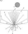
- Figure 1 shows a sensor 1 with a multiplicity of light transmitters 2 and a multiplicity of light receivers 3, which are arranged in a common housing 4, the optical axes 5 of the light transmitters 2 and light receivers 3 being arranged in a fan shape in different angular directions, with the result that a protective field 6 is formed and with a control and evaluation unit 7 for monitoring and evaluating the protective field 6, a camera 8 being connected to the control and evaluation unit 7, the camera images being evaluated by the control and evaluation unit 7.
- Sensor 1 can be a safety sensor or a non-safe sensor. With the help of the camera 8, it is possible to provide diagnostic images and / or configuration images for the sensor 1.
- the camera 8 is connected to the sensor 1 via an interface.
- the interface can be a wired or a wireless interface.
- the camera images are stored, for example, in a memory of the sensor, in a central memory of a system or in a decentralized cloud memory.
- switchable protective fields 6 are provided, for example.
- the protective fields 6 are then switched, for example, depending on the captured camera image.
- the control and evaluation unit 7 detects protective field violations and can output a safety-related shutdown signal in order to stop a dangerous movement of a machine or a vehicle or a part of a machine or to brake the machine, the part of the machine or a vehicle. This can e.g. via safe switching signals e.g. OSSD signals (Output Safety Switching Device signals) or safe distance data, distance data or safe location data of the intervention event can be realized.
- safe switching signals e.g. OSSD signals (Output Safety Switching Device signals) or safe distance data, distance data or safe location data of the intervention event can be realized.
- the angular distance is preferably only a few degrees. For example 1 ° to 20 °, or 1 ° to 10 ° or 1 ° to 5 °.
- the light beams are emitted or received in a fan shape in different angular directions, as a result of which a monitoring area can easily be examined to determine whether objects 9 are present in the monitoring area or not and at what point, ie at what distance the objects 9 are present. Objects 9 can also be measured, or an environmental contour and its change can be recorded.
- the monitoring area is monitored within a fan-shaped level by the fan-shaped emission of the light beams or the fan-shaped reception.
- the light transmitter 2 or light receiver 3 can, for example, also be arranged radially symmetrically in the circumference of a cylinder.
- the sensor can be manufactured with a high degree of angular accuracy, since the light transmitters and light receivers are fixed in place and the light beams reach the monitoring area directly, without moving parts. During the production of the sensor, the angular accuracy of the angular directions can be checked and set. This ensures that each sensor maintains a certain required minimum angular accuracy.
- the sensor 1 is a sensor 1 according to the time-of-flight method.
- the camera 8 is arranged in the housing 4 of the sensor 1.
- the camera 8 is already integrated and optionally already firmly aligned.
- the camera 8 can be arranged in the housing 4 in an adjustable and adjustable manner.
- the field of view of the camera 8 is directed at the protective field 6 and at least the area of the protective field 6 is captured by the camera 8.
- events in the protective field 6, for example interventions in the protective field 6 by the camera 8 can be analyzed.
- the camera 8 can thus determine the cause of the intervention.
- the camera 8 can be activated permanently or temporarily.
- an event in the protective field 6 starts recording the camera 8.
- the camera 8 can thus be triggered by the intervention or a specific event in the protective field 6.
- the camera recording is only activated during the intervention or event and the recording is saved.
- rare interventions or events can be detected without the camera 8 being constantly activated or without the camera images having to be stored continuously.
- the camera images of a short period of time are constantly saved and the recording is stopped in the event of an intervention or event, so that the history of the intervention is documented by the stored camera images.
- a trigger for the camera 8 can, however, also according to Figure 2 are triggered by an external machine control event.
- machine signals that can be read in via an interface can trigger the camera 8.
- the production goods or objects 9 are recorded and recorded by the camera 8 in a running production, for example in order to carry out a presence check, a maintenance check or a quality check.
- a recording mode of the camera 8 can be set in the control and evaluation unit 7.
- the recording mode of the camera 8 can be a film mode, a single image mode or a series image mode.
- control and evaluation unit 7 is designed to carry out object recognition on the basis of the camera recording and to distinguish permissible objects 10 from impermissible objects, and to suppress an object detection signal of the sensor 1 in the case of permissible objects 10.
- objects 9 are detected that pass through a passage to a processing station.
- the objects 9 are captured and identified by the camera 8. If the objects 10 are permissible, the sensor 1 is muted, ie bridged, so that the objects 9 can pass through. However, if impermissible objects such as people are detected, who are not allowed to pass through the passage, the sensor 1 remains active and the people are detected by the sensor 1, whereby, for example, a dangerous movement is stopped.
- the camera 8 is a camera 8 according to the time-of-flight method.
- the camera 8 itself can generate three-dimensional images, which enables better object recognition or object classification.
- control and evaluation unit 7 is designed to carry out code recognition on the basis of the camera recording and characters of a bar code or matrix code can be read by the control and evaluation unit 7.
- Configurations provided in sensor 1 can thereby be activated.
- the captured barcode information can also be passed on to downstream processes and systems, whereby a production system can be controlled.
- an autonomous vehicle 12 has a sensor 1 according to the invention.
- the camera 8 can already be used when the autonomous vehicle 12 is started up.
- the camera 8 can actively generate images of the surroundings and store them when an environment is first used, for example a warehouse for the purpose of mapping, that is to say the detection of the environment.
- the spatial surroundings of the vehicle 12 can be reconstructed from the images. For example, the corners, edges, walls, surfaces, columns, routes, etc. are recognized and taught.
Landscapes
- Engineering & Computer Science (AREA)
- Physics & Mathematics (AREA)
- General Physics & Mathematics (AREA)
- Electromagnetism (AREA)
- Radar, Positioning & Navigation (AREA)
- Remote Sensing (AREA)
- Computer Networks & Wireless Communication (AREA)
- Health & Medical Sciences (AREA)
- Vascular Medicine (AREA)
- Multimedia (AREA)
- Theoretical Computer Science (AREA)
- General Health & Medical Sciences (AREA)
- Traffic Control Systems (AREA)
- Geophysics And Detection Of Objects (AREA)
- Optical Radar Systems And Details Thereof (AREA)
Abstract
Description
- Die vorliegende Erfindung betrifft einen Sensor nach dem Oberbegriff von Anspruch 1 und ein autonomes Fahrzeug nach dem Oberbegriff von Anspruch 10.
- Autonome Fahrzeuge, wie mobile Plattformen, fahrerlose Transportsysteme oder fahrerlose Transportfahrzeuge sind mit Sicherheitssensorik zum Personen- und Kollisionsschutz ausgerüstet.
- Zur Absicherung von fahrerlosen Transportsystemen werden beispielsweise Laserscanner oder Sicherheitslaserscanner verwendet.
- Eine Aufgabe der Erfindung besteht darin, einen verbesserten Sensor bereitzustellen, welcher besser diagnostizierbar ist oder zur besseren Objekterkennung eingesetzt werden kann.
- Die Aufgabe wird gemäß Anspruch 1 gelöst durch einen Sensor mit einer Vielzahl von Lichtsendern und einer Vielzahl von Lichtempfängern, welche in einem gemeinsamen Gehäuse angeordnet sind, wobei die optischen Achsen der Lichtsender und Lichtempfänger parallel oder in verschiedenen Winkelrichtungen mit Winkelabständen fächerförmig angeordnet sind, wodurch ein Schutzfeld gebildet ist und mit einer Steuer-und Auswerteeinheit zur Überwachung und Auswertung des Schutzfeldes, wobei mit der Steuer- und Auswerteeinheit eine Kamera verbunden ist, wobei die Kamerabilder von der Steuer- und Auswerteeinheit ausgewertet werden.
- Bei dem Sensor kann es sich um einen Sicherheitssensor oder um einen nicht sicheren Sensor handeln. Mit Hilfe der Kamera ist es möglich, Diagnosebilder und/oder Konfigurationsbilder für den Sensor bereit zu stellen. Gemäß der Erfindung wird ein System mit einem Sensor und einer Kamera sowie der Steuer- und Auswerteeinheit bereitgestellt.
- Beispielsweise ist die Kamera über eine Schnittstelle mit dem Sensor verbunden. Die Kamera kann beispielsweise in einem eigenen getrennten Gehäuse angeordnet sein. Bei der Schnittstelle kann es sich um eine drahtgebundene oder um eine drahtlose Schnittstelle handeln. Bei den drahtgebundenen Schnittstellen handelt es sich beispielweise um Ethernet oder andere Netzwerke oder Feldbusse. Bei den drahtlosen Schnittstellen handelt es sich beispielsweise um drahtloses Ethernet (WLAN), drahtlose Nahfeldkommunikation (NFC) oder beispielsweise Bluetooth.
- Die Kamerabilder werden beispielsweise in einem Speicher des Sensors, einem zentralen Speicher einer Anlage oder in einem dezentralen Cloud-Speicher abgespeichert.
- Hierzu sind beispielsweise Softwarewerkzeuge des Herstellers vorgesehen, wie beispielsweise einheitliche Bedien-, Konfigurations- und Verwaltungssoftware, beispielsweise mit dem Namen SOPAS, SOPAS Air oder Safety Designer der Anmelderin.
- Gemäß der Erfindung sind beispielsweise mehrere umschaltbare Schutzfelder vorgesehen. Die Schutzfelder werden dann beispielsweise abhängig von dem erfassten Kamerabild umgeschaltet.
- Die Abstände der ausgesendeten Strahlen der Lichtsender vergrößern sich optional mit größer werdendem Abstand zum optoelektronischen Sensor und/oder die Abstände der empfangenen Strahlen der Lichtempfänger verkleinern sich optional mit kleiner werdendem Abstand zum optoelektronischen Sensor.
- Bei dem Sensor kann es sich um einen Sicherheitssensor handeln. Sicherheit ist gemäß vorliegender Erfindung Sicherheit im Sinne von Maschinensicherheit. Beispielsweise regelt die Norm EN/IEC 61496 die Anforderungen an einen sicheren Sensor bzw. eine sichere berührungslos wirkende Schutzeinrichtung (BWS) zur Absicherung von Gefahrenbereichen. Maschinensicherheit ist in der Norm EN13849 geregelt. Die Sicherheit wird beispielsweise durch einen zweikanaligen oder zweikanalig diversitären Aufbau der Steuer- und Auswerteeinheit zur Fehleraufdeckung und zur Funktionsprüfung gewährleistet. Der abstandsmessende Sensor bzw. Distanzsensor gemäß vorliegender Erfindung ist beispielsweise eigensicher ausgebildet und erkennt interne Fehler. Bei Entdeckung eines Fehlers wird beispielsweise ein Fehlersignal generiert. Weiter verfügt der Sensor bzw. Distanzsensor optional über eine Sensortestung.
- Die Steuer- und Auswerteeinheit erkennt Schutzfeldverletzungen und kann ein sicherheitsgerichtetes Abschaltsignal ausgeben, um eine gefahrbringende Bewegung einer Maschine oder eines Fahrzeugs oder eines Teils einer Maschine zu stoppen bzw. die Maschine, das Teil der Maschine oder ein Fahrzeug abzubremsen. Das kann z.B. über sichere Schaltsignale z.B. OSSD-Signale (Output Safety Switching Device-Signale) oder sichere Distanzdaten, Abstandsdaten bzw. sichere Ortsdaten des Eingriffsereignisses realisiert werden.
- Der erfindungsgemäße Sensor ist einfach und preiswert aufgebaut. Da der Sensor ohne mechanisch bewegliche Teile auskommt, weist dieser keinen mechanischen Verschleiß auf und besitzt eine lange Lebensdauer. Beispielsweise kann eine geforderte Einsatzdauer von beispielsweise ca. 20 Jahren mit dem erfindungsgemäßen Sensor erfüllt werden.
- Der optionale Winkelabstand beträgt vorzugsweise nur wenige Grad. Beispielsweise 1° bis 20°, oder 1° bis 10° oder 1° bis 5°.
- Gemäß der Erfindung werden die Lichtstrahlen in verschiedenen Winkelrichtungen fächerförmig ausgesendet bzw. empfangen, wodurch ein Überwachungsbereich dahingehend einfach untersucht werden kann, ob Objekte in dem Überwachungsbereich vorhanden sind oder nicht und an welcher Stelle, d. h. in welcher Entfernung die Objekte vorhanden sind. Weiter können die Objekte vermessen werden, bzw. eine Umgebungskontur und deren Veränderung erfasst werden. Durch die fächerförmige Aussendung der Lichtstrahlen, bzw. das fächerförmige Empfangen wird der Überwachungsbereich innerhalb einer fächerförmigen Ebene überwacht. Die Lichtsender bzw. Lichtempfänger sind beispielsweise im Umfang eines Zylinders radialsymmetrisch angeordnet. Der Laserscanner kann mit einer hohen Winkelgenauigkeit hergestellt werden, da die Lichtsender und Lichtempfänger fest fixiert sind und die Lichtstrahlen direkt, ohne bewegliche Teile in den Überwachungsbereich gelangen. Bei der Produktion des Laserscanners kann die Winkelgenauigkeit der Winkelrichtungen geprüft und eingestellt werden. Dadurch ist gewährleistet, dass jeder Laserscanner eine bestimmte geforderte mindeste Winkelgenauigkeit einhält.
- In Weiterbildung der Erfindung ist der Sensor ein Sensor nach dem Lichtlaufzeitverfahren.
- Ein Lichtlaufzeitsensor basiert beispielsweise auf einem Time-of-flight-Chip nach dem PMD-Verfahren, welche Abstandsmessungen auf Basis einer Phasenlagemessung modulierten Lichts durchführen.
- Ein Distanzsensor bzw. Lichttaster nach dem Lichtlaufzeitprinzip weist mindestens einen Lichtsender auf, der aufeinanderfolgende Lichtimpulse in einen Messbereich aussendet und mindestens einen Lichtempfänger, welcher die an einem Objekt im Messbereich zurückgeworfenen Lichtimpulse aufnimmt und in Form von elektrischen Empfangssignalen einer Steuer- und Auswerteeinheit zuführt, die unter Berücksichtigung der Lichtgeschwindigkeit aus der Zeit zwischen Aussendung und Empfang des Lichtimpulses ein für den Abstand des Objektes zum Lichttaster repräsentatives Abstandssignal ermittelt.
- Gemäß der Erfindung weist ein Lichtempfänger des Distanzsensors mindestens ein Array aus Einzelphotonenlawinendioden auf.
- Einzelphotonenlawinendioden werden auch synonym als,Single Photon Avalanche Diode' kurz SPAD bezeichnet. Andere gängige Bezeichnungen sind 'Silicon Photomultiplier' (SiPM), 'Geigermode Avalanche Photon Diode' oder 'Single Photon Counting Diode'. Einzelphotonenlawinendioden sind in Standard CMOS-Technologie realisierbare photoempfindliche Detektoren, die ähnlich wie Avalanche Photodioden einfallende Photonen in Strompulse konvertieren. Im Gegensatz zu Avalanche Photodioden werden Einzelphotonenlawinendioden jedoch über einer Durchbruchsspannung betrieben. Damit löst bereits ein einzelnes einfallendes Photon einen Lawineneffekt aus, der als Strompuls detektiert werden kann. Aufgrund der hohen Sensitivität, nämlich einem Verstärkungsfaktor von 106, können bereits geringste Empfangsleistungen bis zu Einzelphotonen detektiert werden.
- Eine Verwendung eines Lichtlaufzeitsensors, insbesondere die Verwendung von Einzelphotonenlawinendioden in Kombination mit Pulslasern liefern Abstandsinformationen mit einer Genauigkeit von beispielsweise bis zu ca. einem Millimeter. Gleichzeitig erlaubt eine einfache Vorsatzoptik über eine Fokussierung die Realisierung von guter Ortsselektivität und Abgrenzung gegenüber Störlicht.
- Zur Entfernungsmessung sind verschiedene Lichtlaufzeitverfahren mit einer entsprechenden Auswertung implementierbar.
- Es kann ein Pulsverfahren vorgesehen sein. Beispielsweise sind ein oder mehrere Zeit-zu-Digital-Konverter (time-to-digital-converter) für das Pulsverfahren vorgesehen, in dem jedes Einzelphotonenereignis mit einem Zeitstempel versehen wird. Bei einem Nutzsignal treten daher mehrere Zeitstempel korreliert auf. Die Messwertgenerierung erfolgt statistisch. Hintergrundlicht erzeugt hingegen zufällig verteilte Zeitstempel.
- Weiter kann ein CW-Verfahren (Continuous Wave) bzw. das synonyme Dauerstrich-Verfahren eingesetzt werden, wobei ein zeitlich durchgängig moduliertes Lichtsignal eingesetzt wird. Bei diesem Verfahren werden über ein Gating-Signal die Einzelphotonenevents in zwei Zähler verteilt und aus dem Verhältnis der Zählerstände eine Phase berechnet.
- Weiter können analoge Signale des Einzelphotonendiodenarrays ausgewertet werden. Diese werden mit einem Schwellwert verglichen, werden gesampelt oder werden mit statistischen Methoden ausgewertet.
- Bei der Auswertung nach dem Lichtlaufzeitverfahren kann zusätzlich zum Abstandswert auch ein Amplitudenwert generiert werden, z. B. durch ein Histogramm der Zeitstempel, durch eine Zählrate oder durch eine Spannungsamplitude bei einer analogen Auswertung. Durch den Amplitudenwert kann eine Plausibilitätsprüfung, insbesondere bei sicherheitstechnischen Anwendungen durchgeführt werden.
- Die Verwendung von Einzelphotonenlawinendioden bietet folgende Vorteile: Einzelphotonenlawinendioden sind in einem Standard CMOS Prozess herstellbar. Damit ist der Lichttaster hoch integrierbar, z. B. als ASIC. Der Lichtsender, beispielsweise ein VSCEL, eine Laserdiode oder eine Leuchtdiode und die Steuer- und Auswerteeinheit bzw. eine getrennte Lichtsenderansteuerung sind ebenfalls auf dem Chip bzw. im Gehäuse integrierbar.
- Der Distanzsensor bzw. Lichttaster ist kostengünstiger als bisher in der Sicherheitstechnik übliche photoempfindliche Empfänger. Durch Mehrfachanordnung von Lichttastern sind sehr kompakte Systeme möglich. Durch die Verwendung von Einzelphotonenlawinendioden ist eine hohe Empfindlichkeit bis zu einzelnen Photonen gegeben. Dadurch kann eine optionale Optik sehr kompakt ausgeführt werden.
- In Weiterbildung der Erfindung ist die Kamera im Gehäuse des Sensors angeordnet. Dadurch ist die Kamera bereits integriert und optional bereits fest ausgerichtet. Die Kamera ist dadurch geschützt angeordnet und unempfindlich gegenüber Umwelteinflüssen. Die Kamera kann in dem Gehäuse verstellbar und justierbar angeordnet sein.
- In Weiterbildung der Erfindung ist das Sichtfeld der Kamera auf das Schutzfeld gerichtet und mindestens der Bereich des Schutzfeldes wird von der Kamera erfasst. Dadurch können Ereignisse im Schutzfeld beispielsweise Eingriffe in das Schutzfeld durch die Kamera analysiert werden. So kann durch die Kamera festgestellt werden, aufgrund welcher Ursache der Eingriff erfolgte. So kann beispielsweise festgestellt werden, dass mutwillige unerlaubte Eingriffe von nicht zugelassenen Personen in das Schutzfeld stattfinden oder dass beispielsweise aufgrund von bestimmten Störungen wie beispielsweise Störobjekten, ein Eingriff in das Schutzfeld erfolgt. Die Kamera kann hierzu dauerhaft oder zeitweise aktiviert sein.
- In Weiterbildung der Erfindung startet ein Ereignis im Schutzfeld eine Aufnahme der Kamera. Damit kann die Kamera durch den Eingriff oder ein bestimmtes Ereignis im Schutzfeld getriggert werden. Dadurch wird die Kameraaufnahme nur bei dem Eingriff oder Ereignis aktiviert und die Aufnahme gespeichert. Dadurch können seltene Eingriffe oder Ereignisse erfasst werden, ohne dass die Kamera ständig aktiviert ist, oder ohne dass die Kamerabilder ständig gespeichert werden müssen. Jedoch ist es auch vorgesehen, dass die Kamerabilder eines kurzen Zeitraums ständig gespeichert werden und bei einem Eingriff oder Ereignis die Aufnahme gestoppt wird, so dass die Vorgeschichte des Eingriffes durch die gespeicherten Kamerabilder dokumentiert ist.
- Ein Trigger für die Kamera kann jedoch auch durch ein externes Ereignis der Maschinensteuerung ausgelöst werden. So können beispielsweise Maschinensignale, die über eine Schnittstelle einlesbar sind, Auslöser für die Kamera sein. So kann es beispielsweise vorgesehen sein, dass in einer laufenden Produktion die Produktionsgüter durch die Kamera erfasst und aufgenommen werden, um beispielsweise eine Anwesenheitskontrolle, eine Wartungskontrolle oder eine Qualitätskontrolle durchzuführen.
- In Weiterbildung der Erfindung ist ein Aufnahmemodus der Kamera in der Steuer- und Auswerteeinheit einstellbar. Beispielsweise kann der Aufnahmemodus der Kamera ein Filmmodus, ein Einzelbildmodus oder ein Serienbildmodus sein. Weiter können zyklische Bildaufnahmen oder Zeitrafferaufnahmen als Aufnahmemodus vorgesehen sein.
- In Weiterbildung der Erfindung werden die Kameraaufnahmen der Kamera durch die Steuer- und Auswerteeinheit ausgewertet, die zu einem Eingriff in das Schutzfeld geführt haben. Dabei werden die Aufnahmen die Vor- und nach einem Eingriff in das Schutzfeld von der Kamera gemacht werden abgespeichert und analysiert. Dabei zeichnet die Kamera beispielsweise laufend temporär Bilder auf, die dann bei einem Eingriff in das Schutzfeld dauerhaft abgespeichert werden. Dabei werden die beobachteten Szenarien klassifiziert und bewertet und anschließend abgespeichert. So kann beispielsweise festgestellt werden, ob Eingriffe in das Schutzfeld von einer Person, von Materialien oder beispielsweise von Förderfahrzeugen erfolgte. Damit können die Gründe für einen Eingriff in das Schutzfeld in Klassen klassifiziert und/oder diagnostiziert werden.
- In Weiterbildung der Erfindung ist eine Wiederholrate von Aufnahmen für die Kamera in der Steuer- und Auswerteeinheit änderbar. Beispielsweise wird die Wiederholrate abhängig von der Häufigkeit von Eingriffen in das Schutzfeld angepasst. Beispielsweise wird abhängig von einer hohen Anzahl der Eingriffe pro Zeiteinheit in das Schutzfeld die Wiederholrate von Aufnahmen verringert. Beispielsweise ist die Wiederholrate der Aufnahmen in den Intervallen 1 Sekunde, 2 Sekunden, 5 Sekunden, 10 Sekunden, 30 Sekunden, 1 Minute oder 5 Minuten usw. einstellbar.
- Weiter kann die Wiederholrate und/oder eine maximale Wiederholrate für Aufnahmen, beispielsweise generell oder beispielsweise pro Klasse voreingestellt werden. Beispielsweise können 5 Aufnahmen pro Minute oder 5 Aufnahmen pro Stunde voreingestellt werden.
- Weiter können auch Aufnahmezeiten ignoriert werden, so dass in bestimmten Intervallen keine Aufnahmen gespeichert werden. Wenn beispielsweise jede Minute ein neues Teil bzw. ein Objekt angeliefert wird und daraus eine zulässige Unterbrechung der Lichtstrahlen stattfindet, dann kann in der Steuer- und Auswerteeinheit voreingestellt werden, dass keine Aufnahmen in der Zeit, wenn das Teil bzw. das Objekt angeliefert wird erfolgt. Vor und nach der zulässigen Unterbrechung werden aber weiterhin Aufnahmen gemacht und ausgewertet. Die Zeitdauer der Anlieferung und zulässigen Unterbrechung des Sensors kann beispielsweise 20 Sekunden dauern.
- In Weiterbildung der Erfindung ist die Steuer- und Auswerteeinheit ausgebildet, aufgrund der Kameraaufnahme eine Codeerkennung durchzuführen und Zeichen eines Strichcodes oder Matrixcodes sind durch die Steuer- und Auswerteeinheit lesbar. Dadurch können vorgesehene Konfigurationen im Sensor aktiviert werden. So kann es beispielsweise vorgesehen sein, dass auf Paketen angebrachte Barcodes gelesen werden und abhängig von den gelesenen Barcodes eine Änderung der aktiven Schutzfelder vorgenommen wird. Die erfasste Barcodeinformation kann dabei auch an nachgelagerte Prozesse und Anlagen weitergegeben werden, wodurch eine Produktionsanlage gesteuert werden kann.
- In Weiterbildung der Erfindung ist die Steuer- und Auswerteeinheit ausgebildet, aufgrund der Kameraaufnahme eine Objekterkennung durchzuführen und zulässige von unzulässigen Objekten zu unterscheiden, und bei zulässigen Objekten ein Objektfeststellungssignal des Sensors zu unterdrücken. Beispielsweise werden durch die Kamera Objekte erfasst, die einen Durchgang zu einer Verarbeitungsstation passieren. Durch die Kamera werden die Objekte erfasst und identifiziert. Handelt es sich um zulässige Objekte, wird der Sensor gemutet, d. h. überbrückt, so dass die Objekte den Durchgang passieren können. Werden jedoch unzulässige Objekte wie beispielsweise Personen detektiert, die den Durchgang nicht passieren dürfen, so bleibt der Sensor aktiv und die Personen werden durch den Sensor detektiert, wodurch beispielsweise eine gefahrbringende Bewegung stillgesetzt wird.
- In Weiterbildung der Erfindung ist die Kamera eine Kamera nach dem Lichtlaufzeitverfahren. Dadurch kann die Kamera selbst dreidimensionale Bilder erzeugen, wodurch eine bessere Objekterkennung bzw. Objektklassifizierung ermöglicht wird.
- In Weiterbildung der Erfindung ist eine Ausgabeschnittstelle für Messdaten vorgesehen. Die Ausgabeschnittstelle ist mit der Steuer- und Auswerteeinheit verbunden.
- Beispielsweise können über die Ausgabeschnittstelle Entfernungsbilder bzw. Distanzbilder ausgegeben werden. Die Entfernungsbilder können beispielsweise über eine Farbcodierung oder eine Falschfarbendarstellung Tiefenkarten der Aufnahme darstellen. Beispielsweise können fortlaufend aufgezeichnete Entfernungsbilder für ein Mapping einer Werkshalle herangezogen werden oder beispielsweise Navigationsdaten für einfachere autonome Transportfahrzeuge erstellt werden.
- Weiter können die Entfernungsbilder bzw. die Distanzbilder für eine vorgelagerte Qualitätskontrolle und/oder Vollständigkeitskontrolle herangezogen werden.
- Beispielsweise kann gemäß einer Weiterbildung des Sensors eine Aufnahme eines Objektes erfolgen, beispielsweise eines Kartons und ggf. zugehörige Kodeinformationen, beispielsweise Strichkodeinformationen ausgewertet werden. Zusätzlich sind in einer Datenbank die Objekte gespeichert mit zusätzlichen Informationen wie z. B. Volumenangaben oder Abmessungen der Objekte die mit den Daten der Ausgabeschnittstelle kombiniert werden können.
- In Weiterbildung der Erfindung kann bei zulässigen Objekten ein Objektfeststellungssignal unterdrückt werden, wobei diese Funktion auch als Muting, also einer Stummschaltung oder als Ausblendung oder als teilweise Ausblendung von Strahlachsen erfolgen kann. So kann die Unterdrückung des Objektfeststellungssignals basieren auf der Kombination von Abmessungen also Breite und/oder Höhe und/oder Tiefe und/oder Höhe des Objektes und/oder der Geschwindigkeit und/oder einer Objekt-Farbe und/oder einer Objekt-Struktur des Objektes. Beispielsweise werden nur graue Pakete mit kleinen Aufklebern und beispielsweise einer bestimmten Geschwindigkeit, beispielsweise 1 m/s mit einer Toleranz von +/- 20% als zulässige Objekte klassifiziert.
- Beispielsweise kann eine Unterdrückung des Objektfeststellungssignals bei Muting oder bei einer Ausblendung nur dann erfolgen, wenn beispielsweise eine durch den Sensor und/oder durch die Kamera erfasste Objektgeschwindigkeit mit einer vorgegebenen Soll-Geschwindigkeit übereinstimmt. Die Soll-Geschwindigkeit wird entweder fix in der Steuer- und Auswerteeinheit des Sensors konfiguriert oder über externe Signale über eine Eingangsschnittstelle vorgegeben. So können beispielsweise Encoder Signale eines externen Encoders oder eine 1-aus-n Auswertung von z. b. zwei Eingängen vorgenommen werden. So arbeitet beispielsweise eine Maschine im Normalbetrieb mit einer Geschwindigkeit von z. B. 1 m/s und in einem Einrichtbetrieb mit einer Geschwindigkeit von z. B. 0,1 m/s.
- In Weiterbildung der Erfindung weist ein autonomes Fahrzeug einen erfindungsgemäßen Sensor auf.
- Da der Sensor ohne bewegliche Teile auskommt, die beispielsweise beim Einsatz in Fahrzeugen Beschleunigungen ausgesetzt sein können, ist der erfindungsgemäße Sensor unempfindlicher gegen Schwing- und Schockbelastungen und kann daher problemlos in mechanisch bewegten Objekten wie Fahrzeugen insbesondere Flurförderfahrzeugen eingesetzt werden. Dadurch, dass der Sensor ohne bewegliche Teile auskommt, kann der Sensor auch sehr kompakt ausgeführt werden.
- Beispielsweise kann die Kamera bereits bei der Inbetriebnahme des autonomen Fahrzeugs genutzt werden. So kann die Kamera bei einer Erstbefahrung einer Umgebung, beispielsweise einer Lagerhalle zum Zwecke eines Mapping, also der Erfassung der Umgebung, aktiv Bilder der Umgebung erzeugen und diese abspeichern. Aus den Bildern kann die räumliche Umgebung des Fahrzeugs rekonstruiert werden. Dabei werden beispielsweise die Ecken, Kanten, Wände, Flächen, Säulen, Routen usw. erkannt und eingelernt.
- Die Erfindung wird nachstehend auch hinsichtlich weiterer Vorteile und Merkmale unter Bezugnahme auf die beigefügte Zeichnung anhand von Ausführungsbeispielen erläutert. Die Figuren der Zeichnung zeigen in:
- Figur 1
- einen Sensor mit einem fächerförmigen Schutzfeld und einer Kamera;
- Figur 2
- einen Sensor mit parallelen optischen Achsen und einer Kamera;
- Figur 3
- einen Sensor mit parallelen optischen Achsen und einer Kamera zur Erkennung von Strichcodes.
- Figur 4
- ein autonomes Fahrzeug mit einem Sensor und einer Kamera.
- In den nachfolgenden Figuren sind identische Teile mit identischen Bezugszeichen versehen.
-
Figur 1 zeigt einen Sensor 1 mit einer Vielzahl von Lichtsendern 2 und einer Vielzahl von Lichtempfängern 3, welche in einem gemeinsamen Gehäuse 4 angeordnet sind, wobei die optischen Achsen 5 der Lichtsender 2 und Lichtempfänger 3 in verschiedenen Winkelrichtungen mit Winkelabständen fächerförmig angeordnet sind, wodurch ein Schutzfeld 6 gebildet ist und mit einer Steuer-und Auswerteeinheit 7 zur Überwachung und Auswertung des Schutzfeldes 6, wobei mit der Steuer- und Auswerteeinheit 7 eine Kamera 8 verbunden ist, wobei die Kamerabilder von der Steuer- und Auswerteeinheit 7 ausgewertet werden. - Bei dem Sensor 1 kann es sich um einen Sicherheitssensor oder um einen nicht sicheren Sensor handeln. Mit Hilfe der Kamera 8 ist es möglich, Diagnosebilder und/oder Konfigurationsbilder für den Sensor 1 bereit zu stellen.
- Beispielsweise ist die Kamera 8 über eine Schnittstelle mit dem Sensor 1 verbunden. Bei der Schnittstelle kann es sich um eine drahtgebundene oder um eine drahtlose Schnittstelle handeln.
- Die Kamerabilder werden beispielsweise in einem Speicher des Sensors, einem zentralen Speicher einer Anlage oder in einem dezentralen Cloud-Speicher abgespeichert.
- Gemäß der Erfindung sind beispielsweise mehrere umschaltbare Schutzfelder 6 vorgesehen. Die Schutzfelder 6 werden dann beispielsweise abhängig von dem erfassten Kamerabild umgeschaltet.
- Die Steuer- und Auswerteeinheit 7 erkennt Schutzfeldverletzungen und kann ein sicherheitsgerichtetes Abschaltsignal ausgeben, um eine gefahrbringende Bewegung einer Maschine oder eines Fahrzeugs oder eines Teils einer Maschine zu stoppen bzw. die Maschine, das Teil der Maschine oder ein Fahrzeug abzubremsen. Das kann z.B. über sichere Schaltsignale z.B. OSSD-Signale (Output Safety Switching Device-Signale) oder sichere Distanzdaten, Abstandsdaten bzw. sichere Ortsdaten des Eingriffsereignisses realisiert werden.
- Der Winkelabstand beträgt vorzugsweise nur wenige Grad. Beispielsweise 1° bis 20°, oder 1° bis 10° oder 1° bis 5°.
- Gemäß
Figur 1 werden die Lichtstrahlen in verschiedenen Winkelrichtungen fächerförmig ausgesendet bzw. empfangen, wodurch ein Überwachungsbereich dahingehend einfach untersucht werden kann, ob Objekte 9 in dem Überwachungsbereich vorhanden sind oder nicht und an welcher Stelle, d. h. in welcher Entfernung die Objekte 9 vorhanden sind. Weiter können die Objekte 9 vermessen werden, bzw. eine Umgebungskontur und deren Veränderung erfasst werden. Durch die fächerförmige Aussendung der Lichtstrahlen, bzw. das fächerförmige Empfangen wird der Überwachungsbereich innerhalb einer fächerförmigen Ebene überwacht. Die Lichtsender 2 bzw. Lichtempfänger 3 können beispielsweise auch im Umfang eines Zylinders radialsymmetrisch angeordnet sein. Der Sensor kann mit einer hohen Winkelgenauigkeit hergestellt werden, da die Lichtsender und Lichtempfänger fest fixiert sind und die Lichtstrahlen direkt, ohne bewegliche Teile in den Überwachungsbereich gelangen. Bei der Produktion des Sensors kann die Winkelgenauigkeit der Winkelrichtungen geprüft und eingestellt werden. Dadurch ist gewährleistet, dass jeder Sensor eine bestimmte geforderte mindeste Winkelgenauigkeit einhält. - Gemäß
Figur 1 ist der Sensor 1 ein Sensor 1 nach dem Lichtlaufzeitverfahren. - Gemäß
Figur 1 ist die Kamera 8 im Gehäuse 4 des Sensors 1 angeordnet. Dadurch ist die Kamera 8 bereits integriert und optional bereits fest ausgerichtet. Die Kamera 8 kann in dem Gehäuse 4 verstellbar und justierbar angeordnet sein. - Gemäß
Figur 1 ist das Sichtfeld der Kamera 8 auf das Schutzfeld 6 gerichtet und mindestens der Bereich des Schutzfeldes 6 wird von der Kamera 8 erfasst. Dadurch können Ereignisse im Schutzfeld 6, beispielsweise Eingriffe in das Schutzfeld 6 durch die Kamera 8 analysiert werden. So kann durch die Kamera 8 festgestellt werden, aufgrund welcher Ursache der Eingriff erfolgte. Die Kamera 8 kann hierzu dauerhaft oder zeitweise aktiviert sein. - Gemäß
Figur 1 startet ein Ereignis im Schutzfeld 6 eine Aufnahme der Kamera 8. Damit kann die Kamera 8 durch den Eingriff oder ein bestimmtes Ereignis im Schutzfeld 6 getriggert werden. Dadurch wird die Kameraaufnahme nur bei dem Eingriff oder Ereignis aktiviert und die Aufnahme gespeichert. Dadurch können seltene Eingriffe oder Ereignisse erfasst werden, ohne dass die Kamera 8 ständig aktiviert ist, oder ohne dass die Kamerabilder ständig gespeichert werden müssen. Jedoch ist es auch vorgesehen, dass die Kamerabilder eines kurzen Zeitraums ständig gespeichert werden und bei einem Eingriff oder Ereignis die Aufnahme gestoppt wird, so dass die Vorgeschichte des Eingriffes durch die gespeicherten Kamerabilder dokumentiert ist. - Ein Trigger für die Kamera 8 kann jedoch auch gemäß
Figur 2 durch ein externes Ereignis der Maschinensteuerung ausgelöst werden. So können beispielsweise Maschinensignale, die über eine Schnittstelle einlesbar sind, Auslöser für die Kamera 8 sein. So kann es beispielsweise vorgesehen sein, dass in einer laufenden Produktion die Produktionsgüter bzw. Objekte 9 durch die Kamera 8 erfasst und aufgenommen werden, um beispielsweise eine Anwesenheitskontrolle, eine Wartungskontrolle oder eine Qualitätskontrolle durchzuführen. - Gemäß
Figur 2 ist ein Aufnahmemodus der Kamera 8 in der Steuer- und Auswerteeinheit 7 einstellbar. Beispielsweise kann der Aufnahmemodus der Kamera 8 ein Filmmodus, ein Einzelbildmodus oder ein Serienbildmodus sein. - Gemäß
Figur 2 ist die Steuer- und Auswerteeinheit 7 ausgebildet, aufgrund der Kameraaufnahme eine Objekterkennung durchzuführen und zulässige Objekte 10 von unzulässigen Objekten zu unterscheiden, und bei zulässigen Objekten 10 ein Objektfeststellungssignal des Sensors 1 zu unterdrücken. Beispielsweise werden durch die Kamera 8 Objekte 9 erfasst, die einen Durchgang zu einer Verarbeitungsstation passieren. Durch die Kamera 8 werden die Objekte 9 erfasst und identifiziert. Handelt es sich um zulässige Objekte 10, wird der Sensor 1 gemutet, d. h. überbrückt, so dass die Objekte 9 den Durchgang passieren können. Werden jedoch unzulässige Objekte wie beispielsweise Personen detektiert, die den Durchgang nicht passieren dürfen, so bleibt der Sensor 1 aktiv und die Personen werden durch den Sensor 1 detektiert, wodurch beispielsweise eine gefahrbringende Bewegung stillgesetzt wird. - Gemäß
Figur 2 ist die Kamera 8 eine Kamera 8 nach dem Lichtlaufzeitverfahren. Dadurch kann die Kamera 8 selbst dreidimensionale Bilder erzeugen, wodurch eine bessere Objekterkennung bzw. Objektklassifizierung ermöglicht wird. - Gemäß
Figur 3 ist die Steuer- und Auswerteeinheit 7 ausgebildet, aufgrund der Kameraaufnahme eine Codeerkennung durchzuführen und Zeichen eines Strichcodes oder Matrixcodes sind durch die Steuer- und Auswerteeinheit 7 lesbar. Dadurch können vorgesehene Konfigurationen im Sensor 1 aktiviert werden. So kann es beispielsweise vorgesehen sein, dass auf Paketen bzw. Objekten 9 angebrachte Barcodes gelesen werden und abhängig von den gelesenen Barcodes, eine Änderung der aktiven Schutzfelder 6 vorgenommen wird. Die erfasste Barcodeinformation kann dabei auch an nachgelagerte Prozesse und Anlagen weitergegeben werden, wodurch eine Produktionsanlage gesteuert werden kann. - Gemäß
Figur 4 weist ein autonomes Fahrzeug 12 einen erfindungsgemäßen Sensor 1 auf. - Beispielsweise kann die Kamera 8 bereits bei der Inbetriebnahme des autonomen Fahrzeugs 12 genutzt werden. So kann die Kamera 8 bei einer Erstbefahrung einer Umgebung, beispielsweise einer Lagerhalle zum Zwecke eines Mapping, also der Erfassung der Umgebung, aktiv Bilder der Umgebung erzeugen und diese abspeichern. Aus den Bildern kann die räumliche Umgebung des Fahrzeugs 12 rekonstruiert werden. Dabei werden beispielsweise die Ecken, Kanten, Wände, Flächen, Säulen, Routen usw. erkannt und eingelernt.
-
- 1
- Sensor
- 2
- Lichtsender
- 3
- Lichtempfänger
- 4
- Gehäuse
- 5
- optische Achse
- 6
- Schutzfeld
- 7
- Steuer- und Auswerteeinheit
- 8
- Kamera
- 9
- Objekt
- 10
- zulässiges Objekt
- 12
- autonomes Fahrzeug
Claims (13)
- Sensor (1) mit einer Vielzahl von Lichtsendern (2) und einer Vielzahl von Lichtempfängern (3), welche in einem gemeinsamen Gehäuse (4) angeordnet sind, wobei die optischen Achsen (5) der Lichtsender (2) und Lichtempfänger (3) parallel oder in verschiedenen Winkelrichtungen mit Winkelabständen fächerförmig angeordnet sind, wodurch ein Schutzfeld (6) gebildet ist und mit einer Steuer- und Auswerteeinheit (7) zur Überwachung und Auswertung des Schutzfeldes (6),
dadurch gekennzeichnet, dass
mit der Steuer- und Auswerteeinheit (7) eine Kamera (8) verbunden ist, wobei Kamerabilder der Kamera (8) von der Steuer- und Auswerteeinheit (7) ausgewertet werden. - Sensor (1) nach Anspruch 1, dadurch gekennzeichnet, dass der Sensor (1) ein Sensor (1) nach dem Lichtlaufzeitverfahren ist.
- Sensor (1) nach mindestens einem der vorhergehenden Ansprüche, dadurch gekennzeichnet, dass die Kamera (8) im Gehäuse (4) angeordnet ist.
- Sensor (1) nach mindestens einem der vorhergehenden Ansprüche, dadurch gekennzeichnet, dass das Sichtfeld der Kamera (8) auf das Schutzfeld (6) gerichtet ist und mindestens der Bereich des Schutzfeldes (6) von der Kamera (8) erfasst wird.
- Sensor (1) nach mindestens einem der vorhergehenden Ansprüche, dadurch gekennzeichnet, dass ein Ereignis im Schutzfeld (6) eine Aufnahme der Kamera (8) startet.
- Sensor (1) nach mindestens einem der vorhergehenden Ansprüche, dadurch gekennzeichnet, dass ein Aufnahmemodus der Kamera (8) in der Steuer- und Auswerteeinheit (7) einstellbar ist.
- Sensor (1) nach mindestens einem der vorhergehenden Ansprüche, dadurch gekennzeichnet, dass die Kameraaufnahmen der Kamera durch die Steuer-und Auswerteeinheit ausgewertet werden, die zu einem Eingriff in das Schutzfeld geführt haben.
- Sensor (1) nach mindestens einem der vorhergehenden Ansprüche, dadurch gekennzeichnet, dass eine Wiederholrate von Aufnahmen für die Kamera in der Steuer- und Auswerteeinheit änderbar ist.
- Sensor (1) nach mindestens einem der vorhergehenden Ansprüche, dadurch gekennzeichnet, dass die Steuer- und Auswerteeinheit (7) ausgebildet ist, aufgrund der Kameraaufnahme eine Codeerkennung durchzuführen und Zeichen eines Strichcodes oder Matrixcodes durch die Steuer- und Auswerteeinheit (7) identifizierbar sind.
- Sensor (1) nach mindestens einem der vorhergehenden Ansprüche, dadurch gekennzeichnet, dass die Steuer- und Auswerteeinheit (7) ausgebildet ist, aufgrund der Kameraaufnahme der Kamera (8) eine Objekterkennung durchzuführen und zulässige Objekte (10) von unzulässigen Objekten zu unterscheiden, und bei zulässigen Objekten (10) ein Objektfeststellungssignal des Sensors zu unterdrücken.
- Sensor (1) nach mindestens einem der vorhergehenden Ansprüche, dadurch gekennzeichnet, dass die Kamera (8) eine Kamera (8) nach dem Lichtlaufzeitverfahren ist.
- Sensor (1) nach mindestens einem der vorhergehenden Ansprüche, dadurch gekennzeichnet, dass eine Ausgabeschnittstelle für Messdaten vorgesehen ist.
- Autonomes Fahrzeug (12) mit einem Sensor (1) nach mindestens einem der Ansprüche 1 bis 12.
Applications Claiming Priority (1)
| Application Number | Priority Date | Filing Date | Title |
|---|---|---|---|
| DE102018122263.7A DE102018122263B4 (de) | 2018-09-12 | 2018-09-12 | Autonomes Fahrzeug |
Publications (2)
| Publication Number | Publication Date |
|---|---|
| EP3623845A1 true EP3623845A1 (de) | 2020-03-18 |
| EP3623845B1 EP3623845B1 (de) | 2022-06-22 |
Family
ID=67658330
Family Applications (1)
| Application Number | Title | Priority Date | Filing Date |
|---|---|---|---|
| EP19189292.6A Active EP3623845B1 (de) | 2018-09-12 | 2019-07-31 | Sensor und autonomes fahrzeug |
Country Status (4)
| Country | Link |
|---|---|
| US (1) | US11442167B2 (de) |
| EP (1) | EP3623845B1 (de) |
| CN (1) | CN110895335B (de) |
| DE (1) | DE102018122263B4 (de) |
Families Citing this family (6)
| Publication number | Priority date | Publication date | Assignee | Title |
|---|---|---|---|---|
| DE102017123295A1 (de) * | 2017-10-06 | 2019-04-11 | Pilz Gmbh & Co. Kg | Sicherheitssystem zur Absicherung eines kooperativen Betriebs von Menschen, Robotern und Maschinen |
| DE202020102721U1 (de) * | 2020-05-14 | 2020-12-23 | Leuze Electronic Gmbh + Co. Kg | Überwachungseinrichtung |
| CN111722236A (zh) * | 2020-07-02 | 2020-09-29 | 常州市贝叶斯智能科技有限公司 | 一种基于激光测距的餐盘在位检测装置 |
| CN113484928B (zh) * | 2021-07-08 | 2024-02-20 | 杭州海康威视数字技术股份有限公司 | 一种基于测距传感器的通道检测方法、装置、闸机 |
| EP4345512B1 (de) | 2022-09-28 | 2025-10-29 | Siemens Aktiengesellschaft | Überwachungseinrichtung und verfahren zur überwachung einer öffnung |
| DE102023107857A1 (de) * | 2023-03-28 | 2024-10-02 | TRUMPF Werkzeugmaschinen SE + Co. KG | Verfahren und System zur Überwachung eines Sicherheitsbereichs |
Citations (4)
| Publication number | Priority date | Publication date | Assignee | Title |
|---|---|---|---|---|
| DE10026305A1 (de) * | 2000-05-26 | 2001-11-29 | Sick Ag | Optoelektronische Vorrichtung |
| DE102004038906A1 (de) * | 2004-08-11 | 2006-03-09 | Sick Ag | Verfahren zur Erfassung beweglicher Objekte in einer Überwachungseinrichtung und Überwachungseinrichtung |
| EP1927867A1 (de) * | 2006-12-02 | 2008-06-04 | Sick Ag | Optoelektronischer Mehrebenensensor und Verfahren zur Erfassung von Objekten |
| DE202010012985U1 (de) * | 2010-11-25 | 2012-02-27 | Sick Ag | Sensoranordnung zur Objekterkennung |
Family Cites Families (18)
| Publication number | Priority date | Publication date | Assignee | Title |
|---|---|---|---|---|
| EP0926582B1 (de) * | 1997-12-24 | 2000-09-27 | Datalogic S.P.A. | Vorrichtung und Verfahren zur Fokusierung eines Laserstrahls für optische Codes |
| DE10154861A1 (de) * | 2001-11-08 | 2003-05-22 | Ibeo Automobile Sensor Gmbh | Verfahren zur Bereitstellung von Bildinformationen |
| JP3880837B2 (ja) * | 2001-11-02 | 2007-02-14 | 富士重工業株式会社 | 車外監視装置 |
| US7009500B2 (en) * | 2002-02-13 | 2006-03-07 | Ford Global Technologies, Llc | Method for operating a pre-crash sensing system in a vehicle having a countermeasure system using stereo cameras |
| US20040066500A1 (en) * | 2002-10-02 | 2004-04-08 | Gokturk Salih Burak | Occupancy detection and measurement system and method |
| US7130745B2 (en) * | 2005-02-10 | 2006-10-31 | Toyota Technical Center Usa, Inc. | Vehicle collision warning system |
| EP1901554A4 (de) * | 2005-05-09 | 2016-02-10 | Nikon Corp | Bildgebungsvorrichtung und laufwerkrekordersystem |
| DE102006053002B4 (de) * | 2006-11-10 | 2009-05-14 | Leuze Lumiflex Gmbh + Co. Kg | Optischer Sensor |
| DE102010007520B3 (de) * | 2010-02-11 | 2011-05-05 | Sick Ag | Sicherheitssteuerung mit einer Vielzahl von Anschlüssen für Sensoren |
| DE102012007242A1 (de) * | 2012-03-09 | 2013-09-12 | Fraunhofer-Gesellschaft zur Förderung der angewandten Forschung e.V. | Vorrichtung und Verfahren zur sicheren Mensch-Roboter-Kooperation |
| DE102012006347A1 (de) * | 2012-03-28 | 2013-10-02 | Brose Fahrzeugteile Gmbh & Co. Kg, Hallstadt | Verfahren und Sensorsystem zur Erfassung eines Objektes und/oder zur Bestimmung eines Abstands zwischen dem Objekt und einem Fahrzeug |
| US9187091B2 (en) * | 2012-07-30 | 2015-11-17 | Ford Global Technologies, Llc | Collision detection system with a plausibiity module |
| DE102014108713B3 (de) * | 2014-06-23 | 2015-07-16 | Sick Ag | Rauch- und Brandmelder |
| DE102016103028A1 (de) * | 2016-02-22 | 2017-08-24 | Sick Ag | Vorrichtung zum Überwachen eines Überwachungsbereichs |
| EP3217195B1 (de) * | 2016-03-08 | 2023-04-26 | Leuze electronic GmbH + Co KG | Optischer sensor |
| DE202017102411U1 (de) * | 2017-04-25 | 2017-05-15 | Leuze Electronic Gmbh + Co Kg | Vorrichtung zur Absicherung einer Anlage |
| EP3454298B1 (de) * | 2017-09-06 | 2019-08-07 | Sick AG | Kameravorrichtung und verfahren zur erfassung eines stromes aus objekten |
| US20190204845A1 (en) * | 2017-12-29 | 2019-07-04 | Waymo Llc | Sensor integration for large autonomous vehicles |
-
2018
- 2018-09-12 DE DE102018122263.7A patent/DE102018122263B4/de active Active
-
2019
- 2019-07-31 EP EP19189292.6A patent/EP3623845B1/de active Active
- 2019-09-10 US US16/565,987 patent/US11442167B2/en active Active
- 2019-09-12 CN CN201910863997.6A patent/CN110895335B/zh active Active
Patent Citations (4)
| Publication number | Priority date | Publication date | Assignee | Title |
|---|---|---|---|---|
| DE10026305A1 (de) * | 2000-05-26 | 2001-11-29 | Sick Ag | Optoelektronische Vorrichtung |
| DE102004038906A1 (de) * | 2004-08-11 | 2006-03-09 | Sick Ag | Verfahren zur Erfassung beweglicher Objekte in einer Überwachungseinrichtung und Überwachungseinrichtung |
| EP1927867A1 (de) * | 2006-12-02 | 2008-06-04 | Sick Ag | Optoelektronischer Mehrebenensensor und Verfahren zur Erfassung von Objekten |
| DE202010012985U1 (de) * | 2010-11-25 | 2012-02-27 | Sick Ag | Sensoranordnung zur Objekterkennung |
Also Published As
| Publication number | Publication date |
|---|---|
| DE102018122263A1 (de) | 2020-03-12 |
| EP3623845B1 (de) | 2022-06-22 |
| CN110895335A (zh) | 2020-03-20 |
| US11442167B2 (en) | 2022-09-13 |
| DE102018122263B4 (de) | 2021-03-18 |
| US20200081123A1 (en) | 2020-03-12 |
| CN110895335B (zh) | 2023-01-06 |
Similar Documents
| Publication | Publication Date | Title |
|---|---|---|
| EP3623845B1 (de) | Sensor und autonomes fahrzeug | |
| EP3091272B1 (de) | Lichtgitter | |
| EP3136127B1 (de) | Distanzsensor und verfahren mit einem distanzsensor | |
| EP3091271B1 (de) | Lichttaster | |
| EP2824478B1 (de) | Optoelektronischer Sensor und Verfahren zur Erfassung und Abstandsbestimmung von Objekten in einem Überwachungsbereich | |
| EP3557286B1 (de) | Optoelektronischer sensor und verfahren zur erfassung und abstandsbestimmung eines objekts | |
| DE102010061382A1 (de) | Optoelektronischer Sensor und Verfahren zur Erfassung und Abstandsbestimmung von Objekten | |
| EP3671276A1 (de) | Optoelektronischer sensor und verfahren zur erfassung eines objekts | |
| EP3418846A1 (de) | Vorrichtung zur sicherheitssteuerung einer maschine | |
| EP3208511B1 (de) | Vorrichtung zum überwachen des überwachungsbereichs eines führerlosen fahrzeugs | |
| EP3671264A1 (de) | Sensor und verfahren zur erfassung eines objekts | |
| EP3994481B1 (de) | Auslesevorrichtung und lidar-messvorrichtung | |
| DE102019134701A1 (de) | Optoelektronischer Sensor und Verfahren zur Erfassung eines Objekts | |
| DE102017119283B4 (de) | Sensorsystem | |
| EP3994480A1 (de) | Anpassungsvorrichtung und lidar-messvorrichtung | |
| EP2388618A1 (de) | Verfahren zur Detektion von Störungen des Messbetriebs einer Ultraschall-Messanordnung eines Kraftfahrzeugs und Kraftfahrzeug | |
| EP3415951B1 (de) | Optischer sensor | |
| DE202018104258U1 (de) | Sicherheitslichtgitter | |
| DE202022103929U1 (de) | Optischer Sensor | |
| DE102010064682B3 (de) | Optoelektronischer Sensor und Verfahren zur Erfassung und Abstandsbestimmung von Objekten | |
| EP3367129B1 (de) | Optoelektronischer sensor und verfahren zur erfassung von objekten | |
| EP3837637B1 (de) | Identifikationseinrichtung, identifikationssystem und verfahren zur identifikation eines objekts | |
| DE202018006124U1 (de) | Sensor | |
| EP3663797A1 (de) | Überwachungsvorrichtung | |
| DE202019103672U1 (de) | Sensorsystem |
Legal Events
| Date | Code | Title | Description |
|---|---|---|---|
| PUAI | Public reference made under article 153(3) epc to a published international application that has entered the european phase |
Free format text: ORIGINAL CODE: 0009012 |
|
| STAA | Information on the status of an ep patent application or granted ep patent |
Free format text: STATUS: THE APPLICATION HAS BEEN PUBLISHED |
|
| AK | Designated contracting states |
Kind code of ref document: A1 Designated state(s): AL AT BE BG CH CY CZ DE DK EE ES FI FR GB GR HR HU IE IS IT LI LT LU LV MC MK MT NL NO PL PT RO RS SE SI SK SM TR |
|
| AX | Request for extension of the european patent |
Extension state: BA ME |
|
| STAA | Information on the status of an ep patent application or granted ep patent |
Free format text: STATUS: REQUEST FOR EXAMINATION WAS MADE |
|
| 17P | Request for examination filed |
Effective date: 20200427 |
|
| RBV | Designated contracting states (corrected) |
Designated state(s): AL AT BE BG CH CY CZ DE DK EE ES FI FR GB GR HR HU IE IS IT LI LT LU LV MC MK MT NL NO PL PT RO RS SE SI SK SM TR |
|
| STAA | Information on the status of an ep patent application or granted ep patent |
Free format text: STATUS: EXAMINATION IS IN PROGRESS |
|
| 17Q | First examination report despatched |
Effective date: 20210225 |
|
| GRAP | Despatch of communication of intention to grant a patent |
Free format text: ORIGINAL CODE: EPIDOSNIGR1 |
|
| STAA | Information on the status of an ep patent application or granted ep patent |
Free format text: STATUS: GRANT OF PATENT IS INTENDED |
|
| RIC1 | Information provided on ipc code assigned before grant |
Ipc: G06V 10/147 20220101ALI20220311BHEP Ipc: G01S 7/481 20060101ALI20220311BHEP Ipc: G01S 17/931 20200101ALI20220311BHEP Ipc: G01S 17/86 20200101ALI20220311BHEP Ipc: G01S 17/04 20200101ALI20220311BHEP Ipc: G01S 17/02 20200101ALI20220311BHEP Ipc: G06K 9/00 20060101ALI20220311BHEP Ipc: G01S 17/93 20200101AFI20220311BHEP |
|
| INTG | Intention to grant announced |
Effective date: 20220401 |
|
| GRAS | Grant fee paid |
Free format text: ORIGINAL CODE: EPIDOSNIGR3 |
|
| GRAA | (expected) grant |
Free format text: ORIGINAL CODE: 0009210 |
|
| STAA | Information on the status of an ep patent application or granted ep patent |
Free format text: STATUS: THE PATENT HAS BEEN GRANTED |
|
| AK | Designated contracting states |
Kind code of ref document: B1 Designated state(s): AL AT BE BG CH CY CZ DE DK EE ES FI FR GB GR HR HU IE IS IT LI LT LU LV MC MK MT NL NO PL PT RO RS SE SI SK SM TR |
|
| REG | Reference to a national code |
Ref country code: GB Ref legal event code: FG4D Free format text: NOT ENGLISH |
|
| REG | Reference to a national code |
Ref country code: CH Ref legal event code: EP |
|
| REG | Reference to a national code |
Ref country code: DE Ref legal event code: R096 Ref document number: 502019004702 Country of ref document: DE |
|
| REG | Reference to a national code |
Ref country code: AT Ref legal event code: REF Ref document number: 1500116 Country of ref document: AT Kind code of ref document: T Effective date: 20220715 |
|
| REG | Reference to a national code |
Ref country code: IE Ref legal event code: FG4D Free format text: LANGUAGE OF EP DOCUMENT: GERMAN |
|
| REG | Reference to a national code |
Ref country code: LT Ref legal event code: MG9D |
|
| REG | Reference to a national code |
Ref country code: NL Ref legal event code: MP Effective date: 20220622 |
|
| PG25 | Lapsed in a contracting state [announced via postgrant information from national office to epo] |
Ref country code: SE Free format text: LAPSE BECAUSE OF FAILURE TO SUBMIT A TRANSLATION OF THE DESCRIPTION OR TO PAY THE FEE WITHIN THE PRESCRIBED TIME-LIMIT Effective date: 20220622 Ref country code: NO Free format text: LAPSE BECAUSE OF FAILURE TO SUBMIT A TRANSLATION OF THE DESCRIPTION OR TO PAY THE FEE WITHIN THE PRESCRIBED TIME-LIMIT Effective date: 20220922 Ref country code: LT Free format text: LAPSE BECAUSE OF FAILURE TO SUBMIT A TRANSLATION OF THE DESCRIPTION OR TO PAY THE FEE WITHIN THE PRESCRIBED TIME-LIMIT Effective date: 20220622 Ref country code: HR Free format text: LAPSE BECAUSE OF FAILURE TO SUBMIT A TRANSLATION OF THE DESCRIPTION OR TO PAY THE FEE WITHIN THE PRESCRIBED TIME-LIMIT Effective date: 20220622 Ref country code: GR Free format text: LAPSE BECAUSE OF FAILURE TO SUBMIT A TRANSLATION OF THE DESCRIPTION OR TO PAY THE FEE WITHIN THE PRESCRIBED TIME-LIMIT Effective date: 20220923 Ref country code: FI Free format text: LAPSE BECAUSE OF FAILURE TO SUBMIT A TRANSLATION OF THE DESCRIPTION OR TO PAY THE FEE WITHIN THE PRESCRIBED TIME-LIMIT Effective date: 20220622 Ref country code: BG Free format text: LAPSE BECAUSE OF FAILURE TO SUBMIT A TRANSLATION OF THE DESCRIPTION OR TO PAY THE FEE WITHIN THE PRESCRIBED TIME-LIMIT Effective date: 20220922 |
|
| PG25 | Lapsed in a contracting state [announced via postgrant information from national office to epo] |
Ref country code: RS Free format text: LAPSE BECAUSE OF FAILURE TO SUBMIT A TRANSLATION OF THE DESCRIPTION OR TO PAY THE FEE WITHIN THE PRESCRIBED TIME-LIMIT Effective date: 20220622 Ref country code: LV Free format text: LAPSE BECAUSE OF FAILURE TO SUBMIT A TRANSLATION OF THE DESCRIPTION OR TO PAY THE FEE WITHIN THE PRESCRIBED TIME-LIMIT Effective date: 20220622 |
|
| PG25 | Lapsed in a contracting state [announced via postgrant information from national office to epo] |
Ref country code: NL Free format text: LAPSE BECAUSE OF FAILURE TO SUBMIT A TRANSLATION OF THE DESCRIPTION OR TO PAY THE FEE WITHIN THE PRESCRIBED TIME-LIMIT Effective date: 20220622 |
|
| PG25 | Lapsed in a contracting state [announced via postgrant information from national office to epo] |
Ref country code: SM Free format text: LAPSE BECAUSE OF FAILURE TO SUBMIT A TRANSLATION OF THE DESCRIPTION OR TO PAY THE FEE WITHIN THE PRESCRIBED TIME-LIMIT Effective date: 20220622 Ref country code: SK Free format text: LAPSE BECAUSE OF FAILURE TO SUBMIT A TRANSLATION OF THE DESCRIPTION OR TO PAY THE FEE WITHIN THE PRESCRIBED TIME-LIMIT Effective date: 20220622 Ref country code: RO Free format text: LAPSE BECAUSE OF FAILURE TO SUBMIT A TRANSLATION OF THE DESCRIPTION OR TO PAY THE FEE WITHIN THE PRESCRIBED TIME-LIMIT Effective date: 20220622 Ref country code: PT Free format text: LAPSE BECAUSE OF FAILURE TO SUBMIT A TRANSLATION OF THE DESCRIPTION OR TO PAY THE FEE WITHIN THE PRESCRIBED TIME-LIMIT Effective date: 20221024 Ref country code: ES Free format text: LAPSE BECAUSE OF FAILURE TO SUBMIT A TRANSLATION OF THE DESCRIPTION OR TO PAY THE FEE WITHIN THE PRESCRIBED TIME-LIMIT Effective date: 20220622 Ref country code: EE Free format text: LAPSE BECAUSE OF FAILURE TO SUBMIT A TRANSLATION OF THE DESCRIPTION OR TO PAY THE FEE WITHIN THE PRESCRIBED TIME-LIMIT Effective date: 20220622 Ref country code: CZ Free format text: LAPSE BECAUSE OF FAILURE TO SUBMIT A TRANSLATION OF THE DESCRIPTION OR TO PAY THE FEE WITHIN THE PRESCRIBED TIME-LIMIT Effective date: 20220622 |
|
| PG25 | Lapsed in a contracting state [announced via postgrant information from national office to epo] |
Ref country code: PL Free format text: LAPSE BECAUSE OF FAILURE TO SUBMIT A TRANSLATION OF THE DESCRIPTION OR TO PAY THE FEE WITHIN THE PRESCRIBED TIME-LIMIT Effective date: 20220622 Ref country code: IS Free format text: LAPSE BECAUSE OF FAILURE TO SUBMIT A TRANSLATION OF THE DESCRIPTION OR TO PAY THE FEE WITHIN THE PRESCRIBED TIME-LIMIT Effective date: 20221022 |
|
| REG | Reference to a national code |
Ref country code: DE Ref legal event code: R097 Ref document number: 502019004702 Country of ref document: DE |
|
| REG | Reference to a national code |
Ref country code: BE Ref legal event code: MM Effective date: 20220731 |
|
| PG25 | Lapsed in a contracting state [announced via postgrant information from national office to epo] |
Ref country code: MC Free format text: LAPSE BECAUSE OF FAILURE TO SUBMIT A TRANSLATION OF THE DESCRIPTION OR TO PAY THE FEE WITHIN THE PRESCRIBED TIME-LIMIT Effective date: 20220622 Ref country code: AL Free format text: LAPSE BECAUSE OF FAILURE TO SUBMIT A TRANSLATION OF THE DESCRIPTION OR TO PAY THE FEE WITHIN THE PRESCRIBED TIME-LIMIT Effective date: 20220622 |
|
| PG25 | Lapsed in a contracting state [announced via postgrant information from national office to epo] |
Ref country code: LU Free format text: LAPSE BECAUSE OF NON-PAYMENT OF DUE FEES Effective date: 20220731 Ref country code: DK Free format text: LAPSE BECAUSE OF FAILURE TO SUBMIT A TRANSLATION OF THE DESCRIPTION OR TO PAY THE FEE WITHIN THE PRESCRIBED TIME-LIMIT Effective date: 20220622 |
|
| PLBE | No opposition filed within time limit |
Free format text: ORIGINAL CODE: 0009261 |
|
| STAA | Information on the status of an ep patent application or granted ep patent |
Free format text: STATUS: NO OPPOSITION FILED WITHIN TIME LIMIT |
|
| 26N | No opposition filed |
Effective date: 20230323 |
|
| PG25 | Lapsed in a contracting state [announced via postgrant information from national office to epo] |
Ref country code: BE Free format text: LAPSE BECAUSE OF NON-PAYMENT OF DUE FEES Effective date: 20220731 |
|
| PG25 | Lapsed in a contracting state [announced via postgrant information from national office to epo] |
Ref country code: IE Free format text: LAPSE BECAUSE OF NON-PAYMENT OF DUE FEES Effective date: 20220731 |
|
| PG25 | Lapsed in a contracting state [announced via postgrant information from national office to epo] |
Ref country code: SI Free format text: LAPSE BECAUSE OF FAILURE TO SUBMIT A TRANSLATION OF THE DESCRIPTION OR TO PAY THE FEE WITHIN THE PRESCRIBED TIME-LIMIT Effective date: 20220622 |
|
| PG25 | Lapsed in a contracting state [announced via postgrant information from national office to epo] |
Ref country code: IT Free format text: LAPSE BECAUSE OF FAILURE TO SUBMIT A TRANSLATION OF THE DESCRIPTION OR TO PAY THE FEE WITHIN THE PRESCRIBED TIME-LIMIT Effective date: 20220622 |
|
| PG25 | Lapsed in a contracting state [announced via postgrant information from national office to epo] |
Ref country code: HU Free format text: LAPSE BECAUSE OF FAILURE TO SUBMIT A TRANSLATION OF THE DESCRIPTION OR TO PAY THE FEE WITHIN THE PRESCRIBED TIME-LIMIT; INVALID AB INITIO Effective date: 20190731 |
|
| PG25 | Lapsed in a contracting state [announced via postgrant information from national office to epo] |
Ref country code: MK Free format text: LAPSE BECAUSE OF FAILURE TO SUBMIT A TRANSLATION OF THE DESCRIPTION OR TO PAY THE FEE WITHIN THE PRESCRIBED TIME-LIMIT Effective date: 20220622 Ref country code: CY Free format text: LAPSE BECAUSE OF FAILURE TO SUBMIT A TRANSLATION OF THE DESCRIPTION OR TO PAY THE FEE WITHIN THE PRESCRIBED TIME-LIMIT Effective date: 20220622 |
|
| PG25 | Lapsed in a contracting state [announced via postgrant information from national office to epo] |
Ref country code: MT Free format text: LAPSE BECAUSE OF FAILURE TO SUBMIT A TRANSLATION OF THE DESCRIPTION OR TO PAY THE FEE WITHIN THE PRESCRIBED TIME-LIMIT Effective date: 20220622 |
|
| PG25 | Lapsed in a contracting state [announced via postgrant information from national office to epo] |
Ref country code: BG Free format text: LAPSE BECAUSE OF FAILURE TO SUBMIT A TRANSLATION OF THE DESCRIPTION OR TO PAY THE FEE WITHIN THE PRESCRIBED TIME-LIMIT Effective date: 20220622 |
|
| PG25 | Lapsed in a contracting state [announced via postgrant information from national office to epo] |
Ref country code: BG Free format text: LAPSE BECAUSE OF FAILURE TO SUBMIT A TRANSLATION OF THE DESCRIPTION OR TO PAY THE FEE WITHIN THE PRESCRIBED TIME-LIMIT Effective date: 20220622 |
|
| REG | Reference to a national code |
Ref country code: AT Ref legal event code: MM01 Ref document number: 1500116 Country of ref document: AT Kind code of ref document: T Effective date: 20240731 |
|
| PGFP | Annual fee paid to national office [announced via postgrant information from national office to epo] |
Ref country code: DE Payment date: 20250722 Year of fee payment: 7 |
|
| PGFP | Annual fee paid to national office [announced via postgrant information from national office to epo] |
Ref country code: GB Payment date: 20250724 Year of fee payment: 7 |
|
| PG25 | Lapsed in a contracting state [announced via postgrant information from national office to epo] |
Ref country code: AT Free format text: LAPSE BECAUSE OF NON-PAYMENT OF DUE FEES Effective date: 20240731 |
|
| PGFP | Annual fee paid to national office [announced via postgrant information from national office to epo] |
Ref country code: FR Payment date: 20250723 Year of fee payment: 7 |
|
| PGFP | Annual fee paid to national office [announced via postgrant information from national office to epo] |
Ref country code: CH Payment date: 20250801 Year of fee payment: 7 |
|
| PG25 | Lapsed in a contracting state [announced via postgrant information from national office to epo] |
Ref country code: TR Free format text: LAPSE BECAUSE OF FAILURE TO SUBMIT A TRANSLATION OF THE DESCRIPTION OR TO PAY THE FEE WITHIN THE PRESCRIBED TIME-LIMIT Effective date: 20220622 |
|
| PGFP | Annual fee paid to national office [announced via postgrant information from national office to epo] |
Ref country code: AT Payment date: 20260410 Year of fee payment: 5 |