EP3623654B1 - Magnetic bearing and flywheel accumulator - Google Patents
Magnetic bearing and flywheel accumulator Download PDFInfo
- Publication number
- EP3623654B1 EP3623654B1 EP19197463.3A EP19197463A EP3623654B1 EP 3623654 B1 EP3623654 B1 EP 3623654B1 EP 19197463 A EP19197463 A EP 19197463A EP 3623654 B1 EP3623654 B1 EP 3623654B1
- Authority
- EP
- European Patent Office
- Prior art keywords
- rotor
- bearing
- magnetic
- ring
- axial
- Prior art date
- Legal status (The legal status is an assumption and is not a legal conclusion. Google has not performed a legal analysis and makes no representation as to the accuracy of the status listed.)
- Active
Links
- 230000004907 flux Effects 0.000 claims description 13
- 239000004020 conductor Substances 0.000 claims description 5
- 230000000694 effects Effects 0.000 claims description 5
- 239000000696 magnetic material Substances 0.000 claims description 3
- 238000006073 displacement reaction Methods 0.000 description 2
- 238000005265 energy consumption Methods 0.000 description 2
- 239000007789 gas Substances 0.000 description 2
- 229910000521 B alloy Inorganic materials 0.000 description 1
- RYGMFSIKBFXOCR-UHFFFAOYSA-N Copper Chemical compound [Cu] RYGMFSIKBFXOCR-UHFFFAOYSA-N 0.000 description 1
- QJVKUMXDEUEQLH-UHFFFAOYSA-N [B].[Fe].[Nd] Chemical compound [B].[Fe].[Nd] QJVKUMXDEUEQLH-UHFFFAOYSA-N 0.000 description 1
- 229910052802 copper Inorganic materials 0.000 description 1
- 239000010949 copper Substances 0.000 description 1
- 238000011161 development Methods 0.000 description 1
- 230000018109 developmental process Effects 0.000 description 1
- 238000011982 device technology Methods 0.000 description 1
- 238000005516 engineering process Methods 0.000 description 1
- 230000005484 gravity Effects 0.000 description 1
- 239000007788 liquid Substances 0.000 description 1
- 239000000314 lubricant Substances 0.000 description 1
- 239000000463 material Substances 0.000 description 1
- 238000005096 rolling process Methods 0.000 description 1
- 229920006395 saturated elastomer Polymers 0.000 description 1
- 238000007493 shaping process Methods 0.000 description 1
- 230000003068 static effect Effects 0.000 description 1
Images


Classifications
-
- F—MECHANICAL ENGINEERING; LIGHTING; HEATING; WEAPONS; BLASTING
- F16—ENGINEERING ELEMENTS AND UNITS; GENERAL MEASURES FOR PRODUCING AND MAINTAINING EFFECTIVE FUNCTIONING OF MACHINES OR INSTALLATIONS; THERMAL INSULATION IN GENERAL
- F16C—SHAFTS; FLEXIBLE SHAFTS; ELEMENTS OR CRANKSHAFT MECHANISMS; ROTARY BODIES OTHER THAN GEARING ELEMENTS; BEARINGS
- F16C15/00—Construction of rotary bodies to resist centrifugal force
-
- F—MECHANICAL ENGINEERING; LIGHTING; HEATING; WEAPONS; BLASTING
- F16—ENGINEERING ELEMENTS AND UNITS; GENERAL MEASURES FOR PRODUCING AND MAINTAINING EFFECTIVE FUNCTIONING OF MACHINES OR INSTALLATIONS; THERMAL INSULATION IN GENERAL
- F16C—SHAFTS; FLEXIBLE SHAFTS; ELEMENTS OR CRANKSHAFT MECHANISMS; ROTARY BODIES OTHER THAN GEARING ELEMENTS; BEARINGS
- F16C32/00—Bearings not otherwise provided for
- F16C32/04—Bearings not otherwise provided for using magnetic or electric supporting means
- F16C32/0406—Magnetic bearings
- F16C32/0408—Passive magnetic bearings
- F16C32/041—Passive magnetic bearings with permanent magnets on one part attracting the other part
- F16C32/0412—Passive magnetic bearings with permanent magnets on one part attracting the other part for radial load mainly
-
- F—MECHANICAL ENGINEERING; LIGHTING; HEATING; WEAPONS; BLASTING
- F16—ENGINEERING ELEMENTS AND UNITS; GENERAL MEASURES FOR PRODUCING AND MAINTAINING EFFECTIVE FUNCTIONING OF MACHINES OR INSTALLATIONS; THERMAL INSULATION IN GENERAL
- F16C—SHAFTS; FLEXIBLE SHAFTS; ELEMENTS OR CRANKSHAFT MECHANISMS; ROTARY BODIES OTHER THAN GEARING ELEMENTS; BEARINGS
- F16C32/00—Bearings not otherwise provided for
- F16C32/04—Bearings not otherwise provided for using magnetic or electric supporting means
- F16C32/0406—Magnetic bearings
- F16C32/0408—Passive magnetic bearings
- F16C32/0423—Passive magnetic bearings with permanent magnets on both parts repelling each other
- F16C32/0429—Passive magnetic bearings with permanent magnets on both parts repelling each other for both radial and axial load, e.g. conical magnets
- F16C32/0431—Passive magnetic bearings with permanent magnets on both parts repelling each other for both radial and axial load, e.g. conical magnets with bearings for axial load combined with bearings for radial load
-
- F—MECHANICAL ENGINEERING; LIGHTING; HEATING; WEAPONS; BLASTING
- F16—ENGINEERING ELEMENTS AND UNITS; GENERAL MEASURES FOR PRODUCING AND MAINTAINING EFFECTIVE FUNCTIONING OF MACHINES OR INSTALLATIONS; THERMAL INSULATION IN GENERAL
- F16C—SHAFTS; FLEXIBLE SHAFTS; ELEMENTS OR CRANKSHAFT MECHANISMS; ROTARY BODIES OTHER THAN GEARING ELEMENTS; BEARINGS
- F16C32/00—Bearings not otherwise provided for
- F16C32/04—Bearings not otherwise provided for using magnetic or electric supporting means
- F16C32/0406—Magnetic bearings
- F16C32/044—Active magnetic bearings
- F16C32/0459—Details of the magnetic circuit
- F16C32/0461—Details of the magnetic circuit of stationary parts of the magnetic circuit
- F16C32/0465—Details of the magnetic circuit of stationary parts of the magnetic circuit with permanent magnets provided in the magnetic circuit of the electromagnets
-
- F—MECHANICAL ENGINEERING; LIGHTING; HEATING; WEAPONS; BLASTING
- F16—ENGINEERING ELEMENTS AND UNITS; GENERAL MEASURES FOR PRODUCING AND MAINTAINING EFFECTIVE FUNCTIONING OF MACHINES OR INSTALLATIONS; THERMAL INSULATION IN GENERAL
- F16C—SHAFTS; FLEXIBLE SHAFTS; ELEMENTS OR CRANKSHAFT MECHANISMS; ROTARY BODIES OTHER THAN GEARING ELEMENTS; BEARINGS
- F16C32/00—Bearings not otherwise provided for
- F16C32/04—Bearings not otherwise provided for using magnetic or electric supporting means
- F16C32/0406—Magnetic bearings
- F16C32/044—Active magnetic bearings
- F16C32/0459—Details of the magnetic circuit
- F16C32/0468—Details of the magnetic circuit of moving parts of the magnetic circuit, e.g. of the rotor
-
- F—MECHANICAL ENGINEERING; LIGHTING; HEATING; WEAPONS; BLASTING
- F16—ENGINEERING ELEMENTS AND UNITS; GENERAL MEASURES FOR PRODUCING AND MAINTAINING EFFECTIVE FUNCTIONING OF MACHINES OR INSTALLATIONS; THERMAL INSULATION IN GENERAL
- F16C—SHAFTS; FLEXIBLE SHAFTS; ELEMENTS OR CRANKSHAFT MECHANISMS; ROTARY BODIES OTHER THAN GEARING ELEMENTS; BEARINGS
- F16C2300/00—Application independent of particular apparatuses
- F16C2300/40—Application independent of particular apparatuses related to environment, i.e. operating conditions
- F16C2300/62—Application independent of particular apparatuses related to environment, i.e. operating conditions low pressure, e.g. elements operating under vacuum conditions
-
- F—MECHANICAL ENGINEERING; LIGHTING; HEATING; WEAPONS; BLASTING
- F16—ENGINEERING ELEMENTS AND UNITS; GENERAL MEASURES FOR PRODUCING AND MAINTAINING EFFECTIVE FUNCTIONING OF MACHINES OR INSTALLATIONS; THERMAL INSULATION IN GENERAL
- F16C—SHAFTS; FLEXIBLE SHAFTS; ELEMENTS OR CRANKSHAFT MECHANISMS; ROTARY BODIES OTHER THAN GEARING ELEMENTS; BEARINGS
- F16C2361/00—Apparatus or articles in engineering in general
- F16C2361/55—Flywheel systems
Definitions
- the invention relates to a magnetic bearing of a rotor according to the preamble of claim 1 and a flywheel storage device designed with such a magnetic bearing.
- Rolling and plain bearings are conventionally used to support rotors, in which the contact surfaces are acted upon by a liquid or gaseous lubricant, so that wear and friction are minimized.
- Such conventional bearings reach their limits under certain operating conditions, for example at high or very low ambient temperatures or at extremely high speeds, when used in a vacuum or with aggressive gases.
- non-contact bearings in particular magnetic bearings
- magnetic bearings are used.
- the basic structure of such a magnetic bearing is, for example, in DE 17 50 602 C3 and in the introduction to the description DE 10 2005 028 209 A1 described.
- such magnetic bearings have an axial bearing formed, for example, by a permanent magnet, the permanent magnet being designed in such a way that it bears the weight of the rotor in the axial direction.
- the storage in the radial direction takes place by means of electromagnets, each of which can be controlled via a control circuit.
- the radial position of the rotor is detected via position sensors, so that the electromagnets are controlled in each case via a control loop as a function of the signal from the respective position sensor.
- an active magnetic bearing is also used, the axial gap being detected by a further position sensor.
- a corresponding magnetic bearing is disclosed which is used for levitating a rotor of a flywheel.
- Such magnetic bearings are also used in turbo expansion turbines and compressors, air and gas compressors, vacuum pumps and centrifuges.
- a disadvantage of the above-described systems for levitating a rotor at a defined position in space by means of active field force bearings is that five degrees of freedom (four degrees of freedom in the radial direction, one degree of freedom in the axial direction) have to be actively controlled and, accordingly, five control loops with the associated power electronics and five position sensors required are. This represents a considerable effort in terms of energy, device technology and control technology.
- DE 10 2005 028 209 A1 describes a rotor shaft bearing in which the radial bearing is based on the reluctance principle.
- the radial bearing is based on the reluctance principle.
- separate means for generating a magnetic flux are required, so that the control and device engineering effort is high.
- a magnetic bearing with the features of the preamble of independent claim 1 is from DE 10 2005 030 139 A1 known.
- the invention is based on the object of creating a magnetic bearing which, with a compact structure, enables a rotor to be levitated with little effort.
- the invention is also based on the object of creating a flywheel accumulator, the rotor of which is levitated with little outlay in terms of control engineering and device engineering.
- a rotor is levitated in a housing or a frame by means of a magnetic bearing, which in principle has an axial and a radial bearing, each of which is designed as an active or permanent field force bearing (magnetic bearing).
- the magnetic bearing according to the invention has a position sensor for detecting the axial positions of the rotor and a control circuit for controlling the active axial field force bearing as a function of the signal from the position sensor.
- the radial bearing works according to the reluctance principle with a reluctance-based radial restoring effect, the system always striving for a minimum magnetic resistance that is given with a predetermined nominal position of the rotor with respect to the housing.
- the magnetic bearing also has an axial bearing with at least one permanent field force bearing, which is designed such that it can hold the weight of the rotor and the rotor is held with a predetermined axial gap with respect to a stator of the system.
- a magnetic coil that can be controlled by means of the control circuit is assigned to the permanent field force bearing, which strengthens the magnetic flux of the permanent field force bearing or weakens it when the current is in the opposite direction, so that the axial gap can be adjusted or kept constant depending on the signal from the position sensor by suitable control of the coil by means of the control circuit can.
- the at least one magnetic coil is preferably assigned to both the reluctance-based radial bearing and the active axial bearing.
- the radial rigidity of the magnetic bearing is not implemented via an active control loop, but rather automatically via the reluctance effects described above, the dynamic behavior of the overall system of the magnetic bearing can be easily modeled.
- the axial bearing is designed with two axially spaced permanent field force bearings, each of which is preferably assigned a magnetic coil which can be controlled via a common control circuit.
- These two permanent field force bearings acting in the axial direction are preferably provided in the area of the end sections of the rotor.
- the radial bearing arrangement has two radial bearings arranged at an axial distance, which both work according to the reluctance principle, the permanent field force bearing and the magnetic coil being arranged on a stator of the magnetic bearing and the stator being spaced apart by an axial gap from one connected or connected to the rotor is arranged in one piece with this trained rotor attachment.
- the radial rigidity of the magnetic bearing can be adjusted by slightly varying this geometry.
- the stator and the rotor attachment are formed at least in sections from a magnetically conductive material, preferably a soft magnetic material.
- the profiling on the stator and on the rotor attachment is formed by at least one axially protruding ring or an elevation, the reluctance-optimized flux shaping being effected in that the width of the ring or the elevation is the same on the stator and rotor side, so that if the rings / bumps are covered, the magnetic resistance and the flux density are minimal. It is particularly preferred if at least two concentric rings are formed on the rotor attachment and on the stator.
- the rotor attachment can also be designed in one piece with the rotor.
- additional, preferably circumferential, grooves can be formed on the rings / elevations protruding in the axial direction, these grooves being symmetrical on the stator and rotor side. With a radial displacement of the rotor, these additional grooves cause increased restoring forces (reluctance forces), which arise from the additionally induced distortions of the magnetic field lines.
- the rotor is preferably arranged vertically, the magnetic force generated by means of the permanent field force bearing compensating for the weight of the rotor.
- the rotor can run in a vacuum.
- the housing accommodating the rotor can be designed as a vacuum housing.
- Figure 1 shows an experimental set-up 1 with which the functionality of the magnetic bearing 2 according to the invention of a rotor 4 was confirmed.
- the rotor 4 is mounted in a frame 6.
- a housing preferably a vacuum housing, is then provided instead of the frame 6, in which the rotor 4, designed as a flywheel, is supported via the magnetic bearing 2.
- the in Figure 1 The experimental setup 1 shown in the figure, the rotor 4 is driven by a motor 8 held on the frame 6. In the experimental setup and also in the case of flywheel accumulators, the rotor 4 is upright, ie positioned with a rotor axis arranged in the vertical (direction of gravity). More details of the Experimental setup 1 are based on Figure 2 which shows a vertical section of the experimental setup 1.
- the magnetic bearing 2 has an upper bearing housing 10 and a lower bearing housing 12, which are fixed to the frame 6.
- a magnetic bearing (upper magnetic bearing 14, lower magnetic bearing 16) is arranged in each of the two bearing housings 10, 12, the structure of which is explained in more detail below.
- the rotor 4 has an upper rotor attachment 18, which is operatively connected to the magnetic bearings 14, 16, and a lower rotor attachment 20, which are each connected to the rotor 4 in a rotationally fixed manner.
- the in Figure 1 The indicated motor 8 is accommodated in a motor housing 22 which is fastened to the frame 6.
- a position sensor is arranged in the upper bearing housing 10, which measures the axial gap between a stator and the rotor.
- This position sensor is called axial sensor 23 in the following.
- FIG. 3 On the left the rotor 4 is shown alone, on the right enlarged representations of the upper magnetic bearing 14 and the lower magnetic bearing 16 and the associated components of the magnetic bearing 2 are shown. It can be seen that the rotor attachment 18, 20 is inserted into a corresponding receptacle 28, 30 of the upper or lower rotor end section via a radially recessed fastening pin 24, 26 that plunges into the rotor 4, so that the actual rotor attachment 18, 20 is in Axial direction extends out of the respective end face of the rotor 4.
- the structure of the upper and lower magnetic bearings 14, 16 is largely identical. As in Figure 3 shown, however, the lower rotor attachment 20 is designed so that it does not lie directly on the end face of the actual rotor 4, but is arranged at a distance from it. This spacing is made possible by an extension of the lower fastening pin 26. This axial spacing of the lower rotor attachment 20 with respect to the actual rotor 4 Space is created for receiving the lower magnetic bearing 16, the structure of which corresponds to that of the upper magnetic bearing 14.
- the upper magnetic bearing 14 has an outer bearing ring 32 which is screwed to the bearing housing 10 or 12 and thus forms part of the stator of the magnetic bearing.
- the outer bearing ring 32 is shown in FIG Figure 4 stepped back radially downwards, so that a receiving space 34 is formed, into which a coil holder 36 for a magnetic coil 38 is inserted.
- the bobbin holder 36 is supported inward in the radial direction by an inner bearing ring 40, which likewise dips into the receiving space 34 at least in sections.
- the inner bearing ring 40 and the outer bearing ring 32 are made of a magnetically conductive material, preferably a soft magnetic material, towards the rotor attachment 18, 20.
- the end sections on the rotor attachment side are designed with a geometry that leads to self-centering due to the reluctance forces.
- These end sections of the two bearing rings 32, 40 are referred to as flux shapers 48 and 50, respectively.
- At least these flux shapers 48, 50 are made of a magnetically conductive material in order to optimize self-centering.
- the two flux formers 48, 50 protrude towards the rotor attachment 18 beyond the coil carrier 36, these in the axial direction projecting end sections is formed by a respective tapering of the flow shapers 48, 50, so that two concentric ring structures 52, 54 of the flow shapers 48, 50 are formed on the end face.
- the width B of the inner ring structure 54 is greater than the width b of the outer ring structure 52.
- the rotor attachment 18 is designed with corresponding rings 56, 58, the geometry of which corresponds to that of the ring structure 52, 54.
- the nominal position shown is formed between the ring structures 52, 54 on the one hand and the rings 56, 58 on the other hand, an axial gap 60, which by means of the Figure 2 described axial sensor 23 is detected.
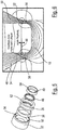
- Figure 5 shows the components of the magnetic bearing 14, 16 in an exploded view.
- the two bearing rings 32, 40 designed as flux formers 48, 50 can be seen, whose end sections on the rotor attachment side - as explained above - are tapered to the ring structures 52, 54.
- the magnetic coil 38 is held on the coil holder 36, which in turn is inserted into the receiving space 34 of the outer bearing ring 32.
- a multiplicity of fixing elements 62 distributed on the circumference for the permanent magnets 46 are formed, so that these are fixed in position in a non-positive or positive manner.
- the permanent magnets 46 can consist, for example, of an iron-neodymium-boron alloy; in the exemplary embodiment shown, the magnetic coil is made of copper.
- the rotor attachments 18, 20 and the bearing rings 32, 40 of the upper and lower magnetic bearings 14, 16 are - as explained above - made at least in sections from a magnetically conductive material.
- the permanent magnets are designed so that they support the weight of the rotor 4 at the operating point of the bearing.
- the upper and the lower magnetic coil 38 can be controlled via a position control circuit 64 with power electronics 66 as a function of the signal from the axial sensor 23 in such a way that the magnetic flux of the Permanent magnets 46 amplified - or with the opposite current flow - is weakened.
- the axial position of the rotor 4 can accordingly be set via the control circuit 64 (position control).
- the ring structures 52, 54 and the corresponding rings 56, 58 can be provided with annular, also concentrically positioned grooves (not shown), which are on both the stator side (flux former 48, 50) and the rotor side (rings 56, 58). In the event of a radial displacement of the rotor, these grooves cause increased restoring forces, which result from the distortions of the magnetic field lines additionally caused by the grooves.
- Figure 6 shows the course of the field lines in the nominal position of the rotor.
- the two ring structures 52, 54 of the stator-side flux formers 48, 50 and the oppositely arranged rings 56, 58 of the rotor attachment 18 are shown the power electronics 66 is adjustable to a certain extent.
- a saturated zone is formed in which the magnetic resistance and the field line density are minimal.
- Figure 7b shows the in Figure 6 The illustrated nominal position of the rotor 4 and the course of the field lines established when the magnet coil 38 is energized and due to the magnetic field of the permanent magnets 46.
- the self-centering geometry of the ring structures 52, 54 and the rings 56, 58 which optimizes the reluctance effect, the magnetic resistance in the nominal position (no radial offset) is minimal.
- Each magnetic field line which is introduced into the rotor 4 or the rotor attachment 18, 20 from the bearing system contributes to supporting the weight of the rotor. If the system is optimized, the amount of material in the rotor through which there is magnetic flow is less than in conventional systems. The eddy current losses, which in magnetic bearings have a significant share in the energy consumption, are therefore significantly lower in the solution according to the invention than in conventional magnetic bearings.
- the magnetic bearing according to the invention can be operated in a very energy-saving manner, since it only has to be brought to an operating point at which the permanent magnet provides all static bearing forces.
- the control loop 64 then only has to compensate for disturbances which act on the system from outside.
- the magnetic bearing according to the invention only requires one active control loop 64.
- the other four degrees of freedom, which in conventional solutions are controlled via four additional control loops, are defined according to the invention via the reluctance-related restoring forces described above in combination with the gyroscopic forces of the rotor 4.
Description
Die Erfindung betrifft eine Magnetlagerung eines Rotors gemäß dem Oberbegriff des Patentanspruches 1 und einen mit einer derartigen Magnetlagerung ausgeführten Schwungradspeicher.The invention relates to a magnetic bearing of a rotor according to the preamble of claim 1 and a flywheel storage device designed with such a magnetic bearing.
Herkömmlich werden zur Lagerung von Rotoren Wälz- und Gleitlager eingesetzt, bei denen die Kontaktflächen mittels eines flüssigen oder gasförmigen Schmierstoffes beaufschlagt sind, so dass der Verschleiß und die Reibung minimiert sind. Derartige herkömmliche Lager kommen bei bestimmten Betriebsbedingungen, beispielsweise bei hohen oder sehr niedrigen Umgebungstemperaturen oder bei extrem hohen Drehzahlen, bei einer Anwendung im Vakuum oder mit aggressiven Gasen an ihre Grenzen.Rolling and plain bearings are conventionally used to support rotors, in which the contact surfaces are acted upon by a liquid or gaseous lubricant, so that wear and friction are minimized. Such conventional bearings reach their limits under certain operating conditions, for example at high or very low ambient temperatures or at extremely high speeds, when used in a vacuum or with aggressive gases.
Als Alternative werden berührungslose Lager, insbesondere Magnetlager verwendet. Der Grundaufbau einer derartigen magnetischen Lagerung ist beispielsweise in der
Demgemäß haben derartige magnetische Lagerungen eine beispielsweise durch einen Permanentmagneten gebildete Axiallagerung, wobei der Permanentmagnet derart ausgelegt ist, dass er das Gewicht des Rotors in Axialrichtung trägt. Die Lagerung in Radialrichtung erfolgt mittels Elektromagneten, die jeweils über einen Regelkreis ansteuerbar sind. Die Radialposition des Rotors wird dabei über Positionssensoren erfasst, so dass die Ansteuerung der Elektromagneten jeweils über einen Regelkreis in Abhängigkeit von dem Signal des jeweiligen Positionssensors erfolgt.Accordingly, such magnetic bearings have an axial bearing formed, for example, by a permanent magnet, the permanent magnet being designed in such a way that it bears the weight of the rotor in the axial direction. The storage in the radial direction takes place by means of electromagnets, each of which can be controlled via a control circuit. The radial position of the rotor is detected via position sensors, so that the electromagnets are controlled in each case via a control loop as a function of the signal from the respective position sensor.
Bei einem weiteren Ausführungsbeispiel wird anstelle des durch einen Permanentmagneten gebildeten Axiallagers ebenfalls ein aktives Magnetlager verwendet, wobei der Axialspalt über einen weiteren Positionssensor erfasst wird.In a further exemplary embodiment, instead of the axial bearing formed by a permanent magnet, an active magnetic bearing is also used, the axial gap being detected by a further position sensor.
In der Druckschrift
Derartige Magnetlagerungen werden auch bei Turbo-Entspannungsturbinen und Verdichtern, Luft- und Gaskompressoren, Vakuumpumpen und Zentrifugen verwendet.Such magnetic bearings are also used in turbo expansion turbines and compressors, air and gas compressors, vacuum pumps and centrifuges.
Möglichkeiten zur Ausgestaltung einer magnetischen Axiallagerung sind in den Druckschriften
Ein Nachteil der vorbeschriebenen Systeme zum Levitieren eines Rotors an einer definierten Position im Raum mittels aktiven Feldkraftlagern besteht darin, dass fünf Freiheitsgrade (vier Freiheitsgrade in Radialrichtung, ein Freiheitsgrad in Axialrichtung) aktiv geregelt werden müssen und dementsprechend fünf Regelkreise mit der zugehörigen Leistungselektronik und fünf Positionssensoren erforderlich sind. Dies stellt einen erheblichen energetischen, vorrichtungstechnischen und regelungstechnischen Aufwand dar.A disadvantage of the above-described systems for levitating a rotor at a defined position in space by means of active field force bearings is that five degrees of freedom (four degrees of freedom in the radial direction, one degree of freedom in the axial direction) have to be actively controlled and, accordingly, five control loops with the associated power electronics and five position sensors required are. This represents a considerable effort in terms of energy, device technology and control technology.
In der vorgenannten
Der Erfindung liegt die Aufgabe zugrunde, eine Magnetlagerung zu schaffen, die bei kompaktem Aufbau ein Levitieren eines Rotors mit geringem Aufwand ermöglicht. Der Erfindung liegt des Weiteren die Aufgabe zugrunde, einen Schwungradspeicher zu schaffen, dessen Rotor mit geringem regelungstechnischen und vorrichtungstechnischen Aufwand levitiert ist.The invention is based on the object of creating a magnetic bearing which, with a compact structure, enables a rotor to be levitated with little effort. The invention is also based on the object of creating a flywheel accumulator, the rotor of which is levitated with little outlay in terms of control engineering and device engineering.
Diese Aufgabe wird im Hinblick auf die Magnetlagerung durch die Merkmalskombination des Patentanspruches 1 und im Hinblick auf den Schwungradspeicher durch die Merkmalskombination des nebengeordneten Patentanspruches 10 gelöst.This object is achieved with regard to the magnetic bearing by the combination of features of claim 1 and with regard to the Flywheel accumulator solved by the combination of features of the
Vorteilhafte Weiterbildungen der Erfindung sind Gegenstand der Unteransprüche.Advantageous further developments of the invention are the subject matter of the subclaims.
Erfindungsgemäß wird ein Rotor in einem Gehäuse oder einem Gestell mittels einer Magnetlagerung levitiert, die im Prinzip eine Axial- und eine Radiallagerung aufweist, die jeweils als aktive oder permanente Feldkraftlager (Magnetlager) ausgeführt sind. Die erfindungsgemäße Magnetlagerung hat einen Positionssensor zur Erfassung der axialen Positionen des Rotors und einen Regelkreis zur Ansteuerung des aktiven axialen Feldkraftlagers in Abhängigkeit von dem Signal des Positionssensors. Erfindungsgemäß arbeitet die Radiallagerung nach dem Reluktanzprinzip mit reluktanzbasierter radialer Rückstellwirkung, wobei das System stets nach einem minimalen magnetischen Widerstand strebt, der bei einer vorbestimmten Nominallage des Rotors mit Bezug zum Gehäuse gegeben ist. Bei einem radialen Versatz des Rotors kommt es auch entsprechend zu einem Feldlinienversatz und einer damit einhergehenden Erhöhung des magnetischen Widerstandes. Dieser Feldlinienversatz bewirkt dann eine Rückstellkraft (Reluktanzkraft), durch die der Rotor radial zurück in seine Nominallage gebracht wird.According to the invention, a rotor is levitated in a housing or a frame by means of a magnetic bearing, which in principle has an axial and a radial bearing, each of which is designed as an active or permanent field force bearing (magnetic bearing). The magnetic bearing according to the invention has a position sensor for detecting the axial positions of the rotor and a control circuit for controlling the active axial field force bearing as a function of the signal from the position sensor. According to the invention, the radial bearing works according to the reluctance principle with a reluctance-based radial restoring effect, the system always striving for a minimum magnetic resistance that is given with a predetermined nominal position of the rotor with respect to the housing. In the event of a radial offset of the rotor, there is also a corresponding field line offset and an associated increase in the magnetic resistance. This field line offset then causes a restoring force (reluctance force), by means of which the rotor is brought back radially into its nominal position.
Erfindungsgemäß hat die Magnetlagerung des Weiteren eine Axiallagerung mit zumindest einem permanenten Feldkraftlager, das derart ausgelegt ist, dass es die Gewichtskraft des Rotors halten kann und der Rotor mit einem vorbestimmten Axialspalt mit Bezug zu einem Stator des Systems gehalten wird. Dem permanenten Feldkraftlager ist eine mittels des Regelkreises ansteuerbare Magnetspule zugeordnet, die den magnetischen Fluss des permanenten Feldkraftlagers stärkt oder bei entgegengesetzter Stromrichtung schwächt, so dass der Axialspalt in Abhängigkeit vom Signal des Positionssensors durch geeignete Ansteuerung der Spule mittels des Regelkreises einstellbar ist oder konstant gehalten werden kann.According to the invention, the magnetic bearing also has an axial bearing with at least one permanent field force bearing, which is designed such that it can hold the weight of the rotor and the rotor is held with a predetermined axial gap with respect to a stator of the system. A magnetic coil that can be controlled by means of the control circuit is assigned to the permanent field force bearing, which strengthens the magnetic flux of the permanent field force bearing or weakens it when the current is in the opposite direction, so that the axial gap can be adjusted or kept constant depending on the signal from the position sensor by suitable control of the coil by means of the control circuit can.
Die zumindest eine Magnetspule ist vorzugsweise sowohl der reluktanzbasierten Radiallagerung als auch der aktiven Axiallagerung zugeordnet.The at least one magnetic coil is preferably assigned to both the reluctance-based radial bearing and the active axial bearing.
Erfindungsgemäß sind somit lediglich ein Regelkreis und ein axialer Positionssensor erforderlich, so dass der vorrichtungstechnische und regelungstechnische Aufwand der erfindungsgemäßen Lösung deutlich geringer als bei den eingangs beschriebenen Lösungen ist. Aus dieser Reduktion der Systemkomplexität resultiert ein signifikant verringerter elektrischer Energieverbrauch. Zudem ist die Ausfallwahrscheinlichkeit des erfindungsgemäßen Magnetlagers deutlich verringert, da sich bei konventionellen Systemen mit fünf Reglern deren Ausfallwahrscheinlichkeiten multiplizieren.According to the invention, only one control loop and one axial position sensor are therefore required, so that the device-related and control-related effort of the solution according to the invention is significantly lower than in the case of the solutions described above. This reduction in system complexity results in a significantly reduced electrical energy consumption. In addition, the failure probability of the magnetic bearing according to the invention is significantly reduced, since in conventional systems with five controllers, their failure probabilities are multiplied.
Da die radiale Steifigkeit der Magnetlagerung nicht über einen aktiven Regelkreis, sondern selbsttätig über die vorbeschriebenen Reluktanzeffekte realisiert wird, lässt sich das dynamische Verhalten des Gesamtsystems der Magnetlagerung einfach modellieren.Since the radial rigidity of the magnetic bearing is not implemented via an active control loop, but rather automatically via the reluctance effects described above, the dynamic behavior of the overall system of the magnetic bearing can be easily modeled.
Entsprechend der Erfindung ist die Axiallagerung mit zwei axial beabstandeten permanenten Feldkraftlagern ausgeführt, denen vorzugsweise jeweils eine Magnetspule zugeordnet ist, die über einen gemeinsamen Regelkreis ansteuerbar sind. Diese beiden in Axialrichtung wirkenden permanenten Feldkraftlager sind vorzugsweise im Bereich der Endabschnitte des Rotors vorgesehen.According to the invention, the axial bearing is designed with two axially spaced permanent field force bearings, each of which is preferably assigned a magnetic coil which can be controlled via a common control circuit. These two permanent field force bearings acting in the axial direction are preferably provided in the area of the end sections of the rotor.
Bei einem Ausführungsbeispiel der Erfindung hat die Radiallageranordnung zwei im Axialabstand angeordnete Radiallager, die beide nach dem Reluktanzprinzip arbeiten, wobei jeweils an einem Stator der Magnetlagerung das permanente Feldkraftlager und die Magnetspule angeordnet sind und der Stator durch einen Axialspalt beabstandet zu einem mit dem Rotor verbundenen oder einstückig mit diesem ausgebildeten Rotoraufsatz angeordnet ist.In one embodiment of the invention, the radial bearing arrangement has two radial bearings arranged at an axial distance, which both work according to the reluctance principle, the permanent field force bearing and the magnetic coil being arranged on a stator of the magnetic bearing and the stator being spaced apart by an axial gap from one connected or connected to the rotor is arranged in one piece with this trained rotor attachment.
Zur Optimierung der Reluktanzkraft sind einander gegenüberliegende Stirnflächen des Stators und des Rotors/Rotoraufsatzes profiliert, wobei diese Profilierung derart erfolgt, dass der magnetische Widerstand zur Erzeugung der die selbstständige radiale Rückstellkraft bewirkenden Reluktanzkraft bei einer radialen Auslenkung maximal ist. Diese eine Selbstzentrierung aufgrund der Reluktanzeffekte bewirkende Geometrie der einander gegenüberliegenden Stirnflächenbereiche des Stators und des Rotors/Rotoraufsatzes wird im Folgenden als "Flussformer" bezeichnet.To optimize the reluctance force, opposing end faces of the stator and the rotor / rotor attachment are profiled, this profiling being carried out in such a way that the magnetic resistance for generating the reluctance force causing the independent radial restoring force is maximum in the event of a radial deflection. This self-centering due to the reluctance effects causing the geometry of Opposite end face areas of the stator and of the rotor / rotor attachment are referred to below as "flux shaper".
Die radiale Steifigkeit der Magnetlagerung kann durch geringfügige Variation dieser Geometrie eingestellt werden.The radial rigidity of the magnetic bearing can be adjusted by slightly varying this geometry.
Der Stator und der Rotoraufsatz sind zumindest abschnittsweise aus einem magnetisch leitfähigen Material, vorzugsweise einem weichmagnetischen Material ausgebildet.The stator and the rotor attachment are formed at least in sections from a magnetically conductive material, preferably a soft magnetic material.
Bei einem Ausführungsbeispiel ist die Profilierung am Stator und am Rotoraufsatz durch zumindest einen in Axialrichtung vorstehenden Ring oder eine Erhebung ausgebildet, wobei die reluktanzoptimierte Flussformung dadurch bewirkt wird, dass die Breite des Ringes bzw. der Erhebung stator- und rotorseitig jeweils gleich ist, so dass bei Überdeckung der Ringe/Erhebungen der magnetische Widerstand und die Flussdichte minimal sind. Dabei wird es besonders bevorzugt, wenn am Rotoraufsatz und am Stator zumindest zwei konzentrische Ringe ausgebildet sind.In one embodiment, the profiling on the stator and on the rotor attachment is formed by at least one axially protruding ring or an elevation, the reluctance-optimized flux shaping being effected in that the width of the ring or the elevation is the same on the stator and rotor side, so that if the rings / bumps are covered, the magnetic resistance and the flux density are minimal. It is particularly preferred if at least two concentric rings are formed on the rotor attachment and on the stator.
Der guten Ordnung halber sei darauf hingewiesen, dass der Rotoraufsatz auch einstückig mit dem Rotor ausgebildet sein kann.For the sake of good order, it should be pointed out that the rotor attachment can also be designed in one piece with the rotor.
Für den Fall, dass eine Erhöhung der radialen Steifigkeit der Magnetlagerung erforderlich ist, können an den in Axialrichtung vorstehenden Ringen/Erhebungen noch zusätzliche, vorzugsweise umlaufende, Rillen ausgebildet werden, wobei diese Rillen stator- und rotorseitig symmetrisch ausgebildet sind. Diese zusätzlichen Rillen bewirken bei einer radialen Verschiebung des Rotors erhöhte Rückstellkräfte (Reluktanzkräfte), welche durch die zusätzlich herbeigeführten Verzerrungen der magnetischen Feldlinien entstehen.In the event that an increase in the radial rigidity of the magnetic bearing is required, additional, preferably circumferential, grooves can be formed on the rings / elevations protruding in the axial direction, these grooves being symmetrical on the stator and rotor side. With a radial displacement of the rotor, these additional grooves cause increased restoring forces (reluctance forces), which arise from the additionally induced distortions of the magnetic field lines.
Der Rotor ist vorzugsweise vertikal angeordnet, wobei die mittels der permanenten Feldkraftlagerung erzeugte Magnetkraft die Gewichtskraft des Rotors kompensiert.The rotor is preferably arranged vertically, the magnetic force generated by means of the permanent field force bearing compensating for the weight of the rotor.
Zur Minimierung der Reibung in den radialen und axialen Spalten kann der Rotor in einem Vakuum laufen. Dazu kann beispielsweise das den Rotor aufnehmende Gehäuse als Vakuumgehäuse ausgebildet sein.To minimize the friction in the radial and axial gaps, the rotor can run in a vacuum. For this purpose, for example, the housing accommodating the rotor can be designed as a vacuum housing.
Bevorzugte Ausführungsbeispiele der Erfindung werden im Folgenden anhand schematischer Zeichnungen näher erläutert. Es zeigen:
-
Figur 1 eine dreidimensionale Darstellung eines Versuchsaufbaus mit einem Rotor, der mittels einer erfindungsgemäßen Magnetlagerung gelagert ist; -
Figur 2Figur 1 ; -
Figur 3 Detaildarstellungen des Rotors der Anordnung gemäß denFiguren 1 und 2 ; -
Figur 4Figur 3 obenliegenden Teils der Magnetlagerung; -
Figur 5 eine Explosionsdarstellung der Magnetlagerung gemäßFigur 4 -
Figur 6Figur 4 -
Figur 7 den Feldlinienverlauf in einer Nominallage des Rotors und bei einem Radialversatz.
-
Figure 1 a three-dimensional representation of an experimental set-up with a rotor which is mounted by means of a magnetic bearing according to the invention; -
Figure 2 a sectional view of the arrangement according toFigure 1 ; -
Figure 3 Detailed representations of the rotor of the arrangement according to theFigures 1 and 2 ; -
Figure 4 a detailed representation of an inFigure 3 overhead part of the magnetic bearing; -
Figure 5 an exploded view of the magnetic bearing according toFigure 4 ; -
Figure 6 the inFigure 4 Enlarged area of the magnetic bearing with the field lines and which are established during operation -
Figure 7 the course of the field lines in a nominal position of the rotor and with a radial offset.
Bei dem in
Demgemäß hat die Magnetlagerung 2 ein oberes Lagergehäuse 10 und ein unteres Lagergehäuse 12, die an dem Gestell 6 festgelegt sind. In den beiden Lagergehäusen 10, 12, ist jeweils ein Magnetlager (oberes Magnetlager 14, unteres Magnetlager 16) angeordnet, dessen Aufbau im Folgenden näher erläutert wird. Bei den dargestellten Ausführungsbeispielen hat der Rotor 4 einen mit den Magnetlagern 14, 16 in Wirkverbindung stehenden oberen Rotoraufsatz 18 und einen unteren Rotoraufsatz 20, die jeweils drehfest mit dem Rotor 4 verbunden sind. Der in
In dem oberen Lagergehäuse 10 ist des Weiteren ein Positionssensor angeordnet, der den Axialspalt zwischen einem Stator und dem Rotor misst. Dieser Positionssensor wird im Folgenden Axialsensor 23 genannt.Furthermore, a position sensor is arranged in the upper bearing
Weitere Einzelheiten der Magnetlager 12, 14 werden anhand
Wie erläutert, ist der Aufbau des oberen und unteren Magnetlagers 14, 16 weitestgehend identisch. Wie in
In dem gehäuse-/gestellfesten oberen bzw. unteren Lagergehäuse 10, 12 (in
Demgemäß hat das obere Magnetlager 14 einen äußeren Lagerring 32, der mit dem Lagergehäuse 10 bzw. 12 verschraubt ist und somit einen Teil des Stators der Magnetlagerung ausbildet. Der äußere Lagerring 32 ist in der Darstellung gemäß
In den Bereich zwischen einer Ringstirnfläche 42 des Aufnahmeraumes 34 und einer oberen Stirnfläche 44 des inneren Lagerringes 40 ist eine Vielzahl von am Umfang verteilten Permanentmagneten 46 eingesetzt. Der innere Lagerring 40 und der äußere Lagerring 32 sind zum Rotoraufsatz 18, 20 hin aus einem magnetisch leitfähigen Werkstoff, vorzugsweise aus einem weichmagnetischen Werkstoff ausgebildet.In the area between an annular end face 42 of the receiving
Wie in der in
Beim konkreten Ausführungsbeispiel stehen die beiden Flussformer 48, 50 zum Rotoraufsatz 18 hin über den Spulenträger 36 hinaus vor, wobei diese in Axialrichtung vorspringenden Endabschnitte durch eine jeweilige Verjüngung der Flussformer 48, 50 ausgebildet ist, so dass sich stirnseitig zwei konzentrische Ringstrukturen 52, 54 der Flussformer 48, 50 ausbilden. Die Breite B der inneren Ringstruktur 54 ist dabei größer als die Breite b der äußeren Ringstruktur 52.In the specific exemplary embodiment, the two
Der Rotoraufsatz 18 ist mit korrespondierenden Ringen 56, 58 ausgeführt, deren Geometrie derjenigen der Ringstruktur 52, 54 entspricht. In der in
Die Permanentmagnete 46 können beispielsweise aus einer Eisen-Neodym-Bor-Legierung bestehen, die Magnetspule ist beim dargestellten Ausführungsbeispiel aus Kupfer hergestellt. Die Rotoraufsätze 18, 20 sowie die Lagerringe 32, 40 der oberen und unteren Magnetlager 14, 16 sind - wie vorstehend erläutert - zumindest abschnittsweise aus einem magnetisch leitfähigen Werkstoff hergestellt.The
Die Permanentmagnete sind so ausgelegt, dass sie die Gewichtskraft des Rotors 4 im Betriebspunkt des Lagers abstützen.The permanent magnets are designed so that they support the weight of the
Wie in
Wie eingangs erläutert, können zur Erhöhung der radialen Steifigkeit die Ringstrukturen 52, 54 und die entsprechenden Ringe 56, 58 mit ringförmigen, ebenfalls konzentrisch positionierten Rillen (nicht dargestellt) versehen werden, die sowohl statorseitig (Flussformer 48, 50) als auch rotorseitig (Ringe 56, 58) ausgebildet werden. Diese Rillen bewirken bei einer radialen Verschiebung des Rotors erhöhte Rückstellkräfte, welche durch die aufgrund der Rillen zusätzlich herbeigeführten Verzerrungen der magnetischen Feldlinien entstehen.As explained at the beginning, to increase the radial rigidity, the
Dies wird nochmals anhand der
Bei einem Radialversatz nach innen (
Jede magnetische Feldlinie, die von dem Lagersystem in den Rotor 4 bzw. den Rotoraufsatz 18, 20 eingeleitet wird, trägt zur Abstützung der Gewichtskraft des Rotors bei. Bei optimierter Auslegung des Systems ist auch die magnetisch durchströmte Materialmenge des Rotors geringer als bei konventionellen Systemen. Die Wirbelstromverluste, die bei Magnetlagern einen wesentlichen Anteil am Energieverbrauch haben, sind dadurch bei der erfindungsgemäßen Lösung deutlich geringer als bei herkömmlichen Magnetlagern.Each magnetic field line which is introduced into the
Das erfindungsgemäße Magnetlager kann sehr energiesparend betrieben werden, da es lediglich in einen Betriebspunkt gebracht werden muss, in dem der Permanentmagnet alle statischen Lagerkräfte bereitstellt. Der Regelkreis 64 muss dann nur Störungen, welche von außen auf das System wirken, ausgleichen.The magnetic bearing according to the invention can be operated in a very energy-saving manner, since it only has to be brought to an operating point at which the permanent magnet provides all static bearing forces. The
Wie vorstehend erläutert, benötigt die erfindungsgemäße Magnetlagerung nur einen aktiven Regelkreis 64. Die anderen vier Freiheitsgrade, die bei herkömmlichen Lösungen über vier weitere Regelkreise geregelt werden, werden erfindungsgemäß über die vorbeschriebenen reluktanzbedingten Rückstellkräfte in Kombination mit den Kreiselkräften des Rotors 4 definiert.As explained above, the magnetic bearing according to the invention only requires one
Offenbart sind eine Magnetlagerung eines Rotors und ein mit einer derartigen Magnetlagerung ausgeführter Schwungradspeicher, wobei die Radiallagerung des Rotors so ausgebildet ist, dass bei einem Radialversatz eine reluktanzbasierende radiale Rückstellung des Rotors erfolgt.Disclosed are a magnetic bearing of a rotor and a flywheel storage device designed with such a magnetic bearing, the radial bearing of the rotor being designed such that a reluctance-based radial return of the rotor takes place in the event of a radial offset.
- 11
- VersuchsaufbauExperimental setup
- 22
- MagnetlagerungMagnetic bearing
- 44th
- Rotorrotor
- 66th
- Gestellframe
- 88th
- Motorengine
- 1010
- oberes Lagergehäuseupper bearing housing
- 1212th
- unteres Lagergehäuselower bearing housing
- 1414th
- oberes Magnetlagerupper magnetic bearing
- 1616
- unteres Magnetlagerlower magnetic bearing
- 1818th
- oberer Rotoraufsatzupper rotor attachment
- 2020th
- unterer Rotoraufsatzlower rotor attachment
- 2222nd
- MotorgehäuseMotor housing
- 2323
- AxialsensorAxial sensor
- 2424
- BefestigungszapfenMounting pin
- 2626th
- BefestigungszapfenMounting pin
- 2828
- Aufnahmerecording
- 3030th
- Aufnahmerecording
- 3232
- äußerer Lagerringouter bearing ring
- 3434
- AufnahmeraumRecording room
- 3636
- SpulenhalterBobbin holder
- 3838
- MagnetspuleSolenoid
- 4040
- innerer Lagerringinner bearing ring
- 4242
- RingstirnflächeRing face
- 4444
- obere Stirnflächeupper face
- 4646
- PermanentmagnetPermanent magnet
- 4848
- FlussformerFlow shaper
- 5050
- FlussformerFlow shaper
- 5252
- RingstrukturRing structure
- 5454
- RingstrukturRing structure
- 5656
- Ringring
- 5858
- Ringring
- 6060
- AxialspaltAxial gap
- 6262
- FixierelementFixing element
- 6464
- RegelkreisControl loop
- 6666
- LeistungselektronikPower electronics
Claims (10)
- Magnetic bearing of a rotor (4), which is levitated in a housing or frame (6), having an axial bearing and a radial bearing assembly, which are each designed as active or permanent field force bearings, and having precisely one control circuit (64) for driving the active field force bearing and having precisely one position sensor for detecting the position of the rotor (4), wherein the radial bearing assembly is designed as a reluctance bearing with a reluctance-based restoring effect and the axial bearing has at least one permanent field force bearing, which has at least one solenoid (38) associated to it, which is drivable via the control circuit (64), for setting an axial gap (60) between an end face region of a stator and an end face region of the rotor (4), in dependence on the signal of the position sensor (23), wherein the axial bearing has two axially spaced, permanent field force bearings, with each of which a solenoid (38) is associated, which are drivable via the common control circuit (64), characterized in in that the field force bearings are provided in the region of end portions of the rotor (4) and act in the axial direction, and wherein rotor attachments (18, 20), which are in operative connection with the magnetic bearings and are connected to the rotor in a rotationally fixed manner, are inserted in each case at an upper and a lower rotor end portion and extend in the axial direction out of the respective end face of the rotor (4).
- The magnetic bearing according to patent claim 1, wherein the radial bearing assembly has two radial bearings arranged at an axial distance, wherein the permanent field force bearing and the solenoid (38) are arranged on a respective stator and the stator is arranged at a distance from the rotor attachment (18, 20), which is connected to the rotor (4) or is formed integrally therewith, via an axial gap (60), wherein mutually opposite end faces of the stator and of the rotor (4) or of the rotor attachment (18, 20) are profiled with a view to optimizing the magnetic flux generating the reluctance forces, wherein the stator and rotor (4) or rotor attachment (18, 20) consist at least in sections of a magnetically conductive material, preferably a soft magnetic material.
- The magnetic bearing according to patent claim 2, wherein at least one axially projecting ring (56, 58) or ring structure (52, 54) is formed on the stator and on the rotor (4) in each case, wherein the stator-side ring (56, 58) and the rotor-side ring structure (52, 54) are each formed with a corresponding ring width (B, b).
- The magnetic bearing according to patent claim 3, wherein at least two concentric ring structures (52, 54) or rings (56, 58) or other axial elevations are formed on the rotor side and stator side.
- The magnetic bearing according to patent claim 3 or 4, wherein each ring structure (52, 54) or each ring (56, 58) has frontal, preferably circumferential, grooves.
- The magnetic bearing according to patent claim 4 or 5, wherein the stator has an inner bearing ring (40) and an outer bearing ring (32), wherein the solenoid (38) is arranged between the inner bearing ring (40) and the outer bearing ring (32) and these are tapered in the direction towards the associated rings (56, 58) of the rotor (4) and the rotor attachment (18, 20), respectively.
- The magnetic bearing according to one of the preceding patent claims, wherein the rotor (4) is arranged upright, wherein the magnetic force generated via the permanent field force bearing compensates for the weight force of the rotor (4).
- The magnetic bearing according to one of the preceding patent claims, wherein the rotor (4) runs in a vacuum.
- The magnetic bearing according to one of the preceding patent claims, wherein the solenoid (38) is associated with the axial bearing and the radial bearing.
- A flywheel accumulator, the rotor (4) of which is supported by a magnetic bearing (2) according to one of the preceding patent claims.
Applications Claiming Priority (1)
| Application Number | Priority Date | Filing Date | Title |
|---|---|---|---|
| DE102018122576.8A DE102018122576A1 (en) | 2018-09-14 | 2018-09-14 | Magnetic bearings and flywheel storage |
Publications (2)
| Publication Number | Publication Date |
|---|---|
| EP3623654A1 EP3623654A1 (en) | 2020-03-18 |
| EP3623654B1 true EP3623654B1 (en) | 2021-11-24 |
Family
ID=67981912
Family Applications (1)
| Application Number | Title | Priority Date | Filing Date |
|---|---|---|---|
| EP19197463.3A Active EP3623654B1 (en) | 2018-09-14 | 2019-09-16 | Magnetic bearing and flywheel accumulator |
Country Status (2)
| Country | Link |
|---|---|
| EP (1) | EP3623654B1 (en) |
| DE (1) | DE102018122576A1 (en) |
Family Cites Families (7)
| Publication number | Priority date | Publication date | Assignee | Title |
|---|---|---|---|---|
| IT942651B (en) * | 1971-09-30 | 1973-04-02 | Elettrorava Spa | RADIAL MAGNETIC BEARING |
| DE3409047A1 (en) * | 1984-03-13 | 1985-09-19 | Kernforschungsanlage Jülich GmbH, 5170 Jülich | MAGNETIC BEARING FOR TRI-AXIS BEARING STABILIZATION OF BODIES |
| DE102005028209B4 (en) * | 2005-06-17 | 2007-04-12 | Siemens Ag | Magnetic bearing device of a rotor shaft against a stator with interlocking rotor disk elements and stator disk elements |
| DE102005030139B4 (en) * | 2005-06-28 | 2007-03-22 | Siemens Ag | Device for the magnetic bearing of a rotor shaft with radial guidance and axial control |
| AT513640B1 (en) * | 2012-12-04 | 2014-08-15 | Tech Universität Wien | Bearing and drive system |
| AT513498B1 (en) * | 2013-01-22 | 2014-05-15 | Tech Universität Wien | Apparatus and method for magnetic axial bearing of a rotor |
| DE102016004714A1 (en) * | 2016-04-19 | 2017-10-19 | Saurer Germany Gmbh & Co. Kg | Spinning rotor shaft, bearing assembly for the active magnetic bearing of such Spinnrotorschafts and spinning rotor drive means |
-
2018
- 2018-09-14 DE DE102018122576.8A patent/DE102018122576A1/en not_active Withdrawn
-
2019
- 2019-09-16 EP EP19197463.3A patent/EP3623654B1/en active Active
Also Published As
| Publication number | Publication date |
|---|---|
| DE102018122576A1 (en) | 2020-03-19 |
| EP3623654A1 (en) | 2020-03-18 |
Similar Documents
| Publication | Publication Date | Title |
|---|---|---|
| EP0344503B1 (en) | Magnetic bearing for a fast rotating vacuum pump | |
| DE102007032933B4 (en) | turbomachinery | |
| DE102005030139B4 (en) | Device for the magnetic bearing of a rotor shaft with radial guidance and axial control | |
| EP3180542B1 (en) | Magnetic damper for vibration absorber | |
| EP1281007B1 (en) | Machine, preferably a vacuum pump, with magnetic bearings | |
| EP3235934B1 (en) | Spinning rotor shaft, bearing assembly for active magnetic bearings of such a spinning rotor shaft and spinning rotor drive | |
| EP2049302B1 (en) | Rotary table mounting and drive device | |
| WO2001086151A2 (en) | Magnetic bearing with damping | |
| WO2002018794A1 (en) | Vacuum pump | |
| EP0332979A2 (en) | Magnetic support with permanent magnets for absorption of the radial bearing stresses | |
| EP1207299A2 (en) | Wind turbine with magnetic bearing | |
| EP2884125B1 (en) | Rotating system | |
| DE3204750C2 (en) | Magnetically mounted turbo molecular pump | |
| WO2009115149A1 (en) | Turbocharger comprising a bearing arrangement for mounting a shaft of the turbocharger | |
| EP3150872A1 (en) | Method for reducing a magnetic stray vector field of a rotary unit with a magnetic bearing comprising permanent magnets by providing a compensating magnet, rotary unit and vacuum pump | |
| EP2708765A2 (en) | Bearing assembly, ventilator, method for guiding a shaft and program | |
| EP1402186A1 (en) | Exhaust gas turbocharger | |
| EP3397423B1 (en) | Damping of vibrations of a machine tool | |
| EP3623654B1 (en) | Magnetic bearing and flywheel accumulator | |
| EP3708843B1 (en) | Method for the manufacture of an electric motor or a vacuum apparatus with such a motor | |
| EP1085224B1 (en) | Rotor with magnetic bearing | |
| DE102009022997B4 (en) | Spindle motor with fluid dynamic bearing system and fixed shaft | |
| EP3926174B1 (en) | Vacuum pump | |
| EP3683449B1 (en) | Magnetic bearing and vacuum apparatus | |
| EP3447299A1 (en) | Adjusting ring |
Legal Events
| Date | Code | Title | Description |
|---|---|---|---|
| PUAI | Public reference made under article 153(3) epc to a published international application that has entered the european phase |
Free format text: ORIGINAL CODE: 0009012 |
|
| STAA | Information on the status of an ep patent application or granted ep patent |
Free format text: STATUS: THE APPLICATION HAS BEEN PUBLISHED |
|
| AK | Designated contracting states |
Kind code of ref document: A1 Designated state(s): AL AT BE BG CH CY CZ DE DK EE ES FI FR GB GR HR HU IE IS IT LI LT LU LV MC MK MT NL NO PL PT RO RS SE SI SK SM TR |
|
| AX | Request for extension of the european patent |
Extension state: BA ME |
|
| STAA | Information on the status of an ep patent application or granted ep patent |
Free format text: STATUS: REQUEST FOR EXAMINATION WAS MADE |
|
| 17P | Request for examination filed |
Effective date: 20200406 |
|
| RBV | Designated contracting states (corrected) |
Designated state(s): AL AT BE BG CH CY CZ DE DK EE ES FI FR GB GR HR HU IE IS IT LI LT LU LV MC MK MT NL NO PL PT RO RS SE SI SK SM TR |
|
| GRAP | Despatch of communication of intention to grant a patent |
Free format text: ORIGINAL CODE: EPIDOSNIGR1 |
|
| STAA | Information on the status of an ep patent application or granted ep patent |
Free format text: STATUS: GRANT OF PATENT IS INTENDED |
|
| INTG | Intention to grant announced |
Effective date: 20210104 |
|
| GRAJ | Information related to disapproval of communication of intention to grant by the applicant or resumption of examination proceedings by the epo deleted |
Free format text: ORIGINAL CODE: EPIDOSDIGR1 |
|
| GRAP | Despatch of communication of intention to grant a patent |
Free format text: ORIGINAL CODE: EPIDOSNIGR1 |
|
| INTG | Intention to grant announced |
Effective date: 20210610 |
|
| INTG | Intention to grant announced |
Effective date: 20210610 |
|
| GRAA | (expected) grant |
Free format text: ORIGINAL CODE: 0009210 |
|
| GRAS | Grant fee paid |
Free format text: ORIGINAL CODE: EPIDOSNIGR3 |
|
| STAA | Information on the status of an ep patent application or granted ep patent |
Free format text: STATUS: THE PATENT HAS BEEN GRANTED |
|
| AK | Designated contracting states |
Kind code of ref document: B1 Designated state(s): AL AT BE BG CH CY CZ DE DK EE ES FI FR GB GR HR HU IE IS IT LI LT LU LV MC MK MT NL NO PL PT RO RS SE SI SK SM TR |
|
| REG | Reference to a national code |
Ref country code: GB Ref legal event code: FG4D Free format text: NOT ENGLISH |
|
| REG | Reference to a national code |
Ref country code: AT Ref legal event code: REF Ref document number: 1450080 Country of ref document: AT Kind code of ref document: T Effective date: 20211215 |
|
| REG | Reference to a national code |
Ref country code: DE Ref legal event code: R096 Ref document number: 502019002825 Country of ref document: DE |
|
| REG | Reference to a national code |
Ref country code: IE Ref legal event code: FG4D Free format text: LANGUAGE OF EP DOCUMENT: GERMAN |
|
| REG | Reference to a national code |
Ref country code: LT Ref legal event code: MG9D |
|
| REG | Reference to a national code |
Ref country code: NL Ref legal event code: MP Effective date: 20211124 |
|
| PG25 | Lapsed in a contracting state [announced via postgrant information from national office to epo] |
Ref country code: RS Free format text: LAPSE BECAUSE OF FAILURE TO SUBMIT A TRANSLATION OF THE DESCRIPTION OR TO PAY THE FEE WITHIN THE PRESCRIBED TIME-LIMIT Effective date: 20211124 Ref country code: LT Free format text: LAPSE BECAUSE OF FAILURE TO SUBMIT A TRANSLATION OF THE DESCRIPTION OR TO PAY THE FEE WITHIN THE PRESCRIBED TIME-LIMIT Effective date: 20211124 Ref country code: FI Free format text: LAPSE BECAUSE OF FAILURE TO SUBMIT A TRANSLATION OF THE DESCRIPTION OR TO PAY THE FEE WITHIN THE PRESCRIBED TIME-LIMIT Effective date: 20211124 Ref country code: BG Free format text: LAPSE BECAUSE OF FAILURE TO SUBMIT A TRANSLATION OF THE DESCRIPTION OR TO PAY THE FEE WITHIN THE PRESCRIBED TIME-LIMIT Effective date: 20220224 |
|
| PG25 | Lapsed in a contracting state [announced via postgrant information from national office to epo] |
Ref country code: IS Free format text: LAPSE BECAUSE OF FAILURE TO SUBMIT A TRANSLATION OF THE DESCRIPTION OR TO PAY THE FEE WITHIN THE PRESCRIBED TIME-LIMIT Effective date: 20220324 Ref country code: SE Free format text: LAPSE BECAUSE OF FAILURE TO SUBMIT A TRANSLATION OF THE DESCRIPTION OR TO PAY THE FEE WITHIN THE PRESCRIBED TIME-LIMIT Effective date: 20211124 Ref country code: PT Free format text: LAPSE BECAUSE OF FAILURE TO SUBMIT A TRANSLATION OF THE DESCRIPTION OR TO PAY THE FEE WITHIN THE PRESCRIBED TIME-LIMIT Effective date: 20220324 Ref country code: PL Free format text: LAPSE BECAUSE OF FAILURE TO SUBMIT A TRANSLATION OF THE DESCRIPTION OR TO PAY THE FEE WITHIN THE PRESCRIBED TIME-LIMIT Effective date: 20211124 Ref country code: NO Free format text: LAPSE BECAUSE OF FAILURE TO SUBMIT A TRANSLATION OF THE DESCRIPTION OR TO PAY THE FEE WITHIN THE PRESCRIBED TIME-LIMIT Effective date: 20220224 Ref country code: NL Free format text: LAPSE BECAUSE OF FAILURE TO SUBMIT A TRANSLATION OF THE DESCRIPTION OR TO PAY THE FEE WITHIN THE PRESCRIBED TIME-LIMIT Effective date: 20211124 Ref country code: LV Free format text: LAPSE BECAUSE OF FAILURE TO SUBMIT A TRANSLATION OF THE DESCRIPTION OR TO PAY THE FEE WITHIN THE PRESCRIBED TIME-LIMIT Effective date: 20211124 Ref country code: HR Free format text: LAPSE BECAUSE OF FAILURE TO SUBMIT A TRANSLATION OF THE DESCRIPTION OR TO PAY THE FEE WITHIN THE PRESCRIBED TIME-LIMIT Effective date: 20211124 Ref country code: GR Free format text: LAPSE BECAUSE OF FAILURE TO SUBMIT A TRANSLATION OF THE DESCRIPTION OR TO PAY THE FEE WITHIN THE PRESCRIBED TIME-LIMIT Effective date: 20220225 Ref country code: ES Free format text: LAPSE BECAUSE OF FAILURE TO SUBMIT A TRANSLATION OF THE DESCRIPTION OR TO PAY THE FEE WITHIN THE PRESCRIBED TIME-LIMIT Effective date: 20211124 |
|
| PG25 | Lapsed in a contracting state [announced via postgrant information from national office to epo] |
Ref country code: SM Free format text: LAPSE BECAUSE OF FAILURE TO SUBMIT A TRANSLATION OF THE DESCRIPTION OR TO PAY THE FEE WITHIN THE PRESCRIBED TIME-LIMIT Effective date: 20211124 Ref country code: SK Free format text: LAPSE BECAUSE OF FAILURE TO SUBMIT A TRANSLATION OF THE DESCRIPTION OR TO PAY THE FEE WITHIN THE PRESCRIBED TIME-LIMIT Effective date: 20211124 Ref country code: RO Free format text: LAPSE BECAUSE OF FAILURE TO SUBMIT A TRANSLATION OF THE DESCRIPTION OR TO PAY THE FEE WITHIN THE PRESCRIBED TIME-LIMIT Effective date: 20211124 Ref country code: EE Free format text: LAPSE BECAUSE OF FAILURE TO SUBMIT A TRANSLATION OF THE DESCRIPTION OR TO PAY THE FEE WITHIN THE PRESCRIBED TIME-LIMIT Effective date: 20211124 Ref country code: DK Free format text: LAPSE BECAUSE OF FAILURE TO SUBMIT A TRANSLATION OF THE DESCRIPTION OR TO PAY THE FEE WITHIN THE PRESCRIBED TIME-LIMIT Effective date: 20211124 Ref country code: CZ Free format text: LAPSE BECAUSE OF FAILURE TO SUBMIT A TRANSLATION OF THE DESCRIPTION OR TO PAY THE FEE WITHIN THE PRESCRIBED TIME-LIMIT Effective date: 20211124 |
|
| REG | Reference to a national code |
Ref country code: DE Ref legal event code: R097 Ref document number: 502019002825 Country of ref document: DE |
|
| PLBE | No opposition filed within time limit |
Free format text: ORIGINAL CODE: 0009261 |
|
| STAA | Information on the status of an ep patent application or granted ep patent |
Free format text: STATUS: NO OPPOSITION FILED WITHIN TIME LIMIT |
|
| PG25 | Lapsed in a contracting state [announced via postgrant information from national office to epo] |
Ref country code: AL Free format text: LAPSE BECAUSE OF FAILURE TO SUBMIT A TRANSLATION OF THE DESCRIPTION OR TO PAY THE FEE WITHIN THE PRESCRIBED TIME-LIMIT Effective date: 20211124 |
|
| 26N | No opposition filed |
Effective date: 20220825 |
|
| PG25 | Lapsed in a contracting state [announced via postgrant information from national office to epo] |
Ref country code: SI Free format text: LAPSE BECAUSE OF FAILURE TO SUBMIT A TRANSLATION OF THE DESCRIPTION OR TO PAY THE FEE WITHIN THE PRESCRIBED TIME-LIMIT Effective date: 20211124 |
|
| REG | Reference to a national code |
Ref country code: DE Ref legal event code: R119 Ref document number: 502019002825 Country of ref document: DE |
|
| PG25 | Lapsed in a contracting state [announced via postgrant information from national office to epo] |
Ref country code: MC Free format text: LAPSE BECAUSE OF FAILURE TO SUBMIT A TRANSLATION OF THE DESCRIPTION OR TO PAY THE FEE WITHIN THE PRESCRIBED TIME-LIMIT Effective date: 20211124 |
|
| REG | Reference to a national code |
Ref country code: CH Ref legal event code: PL |
|
| REG | Reference to a national code |
Ref country code: BE Ref legal event code: MM Effective date: 20220930 |
|
| PG25 | Lapsed in a contracting state [announced via postgrant information from national office to epo] |
Ref country code: IT Free format text: LAPSE BECAUSE OF FAILURE TO SUBMIT A TRANSLATION OF THE DESCRIPTION OR TO PAY THE FEE WITHIN THE PRESCRIBED TIME-LIMIT Effective date: 20211124 |
|
| PG25 | Lapsed in a contracting state [announced via postgrant information from national office to epo] |
Ref country code: LU Free format text: LAPSE BECAUSE OF NON-PAYMENT OF DUE FEES Effective date: 20220916 |
|
| PG25 | Lapsed in a contracting state [announced via postgrant information from national office to epo] |
Ref country code: LI Free format text: LAPSE BECAUSE OF NON-PAYMENT OF DUE FEES Effective date: 20220930 Ref country code: IE Free format text: LAPSE BECAUSE OF NON-PAYMENT OF DUE FEES Effective date: 20220916 Ref country code: FR Free format text: LAPSE BECAUSE OF NON-PAYMENT OF DUE FEES Effective date: 20220930 Ref country code: DE Free format text: LAPSE BECAUSE OF NON-PAYMENT OF DUE FEES Effective date: 20230401 Ref country code: CH Free format text: LAPSE BECAUSE OF NON-PAYMENT OF DUE FEES Effective date: 20220930 |
|
| PG25 | Lapsed in a contracting state [announced via postgrant information from national office to epo] |
Ref country code: BE Free format text: LAPSE BECAUSE OF NON-PAYMENT OF DUE FEES Effective date: 20220930 |
|
| PG25 | Lapsed in a contracting state [announced via postgrant information from national office to epo] |
Ref country code: HU Free format text: LAPSE BECAUSE OF FAILURE TO SUBMIT A TRANSLATION OF THE DESCRIPTION OR TO PAY THE FEE WITHIN THE PRESCRIBED TIME-LIMIT; INVALID AB INITIO Effective date: 20190916 |
|
| PG25 | Lapsed in a contracting state [announced via postgrant information from national office to epo] |
Ref country code: CY Free format text: LAPSE BECAUSE OF FAILURE TO SUBMIT A TRANSLATION OF THE DESCRIPTION OR TO PAY THE FEE WITHIN THE PRESCRIBED TIME-LIMIT Effective date: 20211124 |