EP3623645A1 - Auxiliary device and method for realizing a bolt connection between connecting flanges of a wind turbine mast and a support structure for a wind turbine mast - Google Patents
Auxiliary device and method for realizing a bolt connection between connecting flanges of a wind turbine mast and a support structure for a wind turbine mast Download PDFInfo
- Publication number
- EP3623645A1 EP3623645A1 EP19187096.3A EP19187096A EP3623645A1 EP 3623645 A1 EP3623645 A1 EP 3623645A1 EP 19187096 A EP19187096 A EP 19187096A EP 3623645 A1 EP3623645 A1 EP 3623645A1
- Authority
- EP
- European Patent Office
- Prior art keywords
- support body
- auxiliary device
- connecting flanges
- wind turbine
- moving means
- Prior art date
- Legal status (The legal status is an assumption and is not a legal conclusion. Google has not performed a legal analysis and makes no representation as to the accuracy of the status listed.)
- Granted
Links
Images



Classifications
-
- F—MECHANICAL ENGINEERING; LIGHTING; HEATING; WEAPONS; BLASTING
- F16—ENGINEERING ELEMENTS AND UNITS; GENERAL MEASURES FOR PRODUCING AND MAINTAINING EFFECTIVE FUNCTIONING OF MACHINES OR INSTALLATIONS; THERMAL INSULATION IN GENERAL
- F16B—DEVICES FOR FASTENING OR SECURING CONSTRUCTIONAL ELEMENTS OR MACHINE PARTS TOGETHER, e.g. NAILS, BOLTS, CIRCLIPS, CLAMPS, CLIPS OR WEDGES; JOINTS OR JOINTING
- F16B5/00—Joining sheets or plates, e.g. panels, to one another or to strips or bars parallel to them
- F16B5/02—Joining sheets or plates, e.g. panels, to one another or to strips or bars parallel to them by means of fastening members using screw-thread
-
- E—FIXED CONSTRUCTIONS
- E04—BUILDING
- E04H—BUILDINGS OR LIKE STRUCTURES FOR PARTICULAR PURPOSES; SWIMMING OR SPLASH BATHS OR POOLS; MASTS; FENCING; TENTS OR CANOPIES, IN GENERAL
- E04H12/00—Towers; Masts or poles; Chimney stacks; Water-towers; Methods of erecting such structures
- E04H12/02—Structures made of specified materials
- E04H12/08—Structures made of specified materials of metal
- E04H12/085—Details of flanges for tubular masts
-
- E—FIXED CONSTRUCTIONS
- E04—BUILDING
- E04H—BUILDINGS OR LIKE STRUCTURES FOR PARTICULAR PURPOSES; SWIMMING OR SPLASH BATHS OR POOLS; MASTS; FENCING; TENTS OR CANOPIES, IN GENERAL
- E04H12/00—Towers; Masts or poles; Chimney stacks; Water-towers; Methods of erecting such structures
- E04H12/34—Arrangements for erecting or lowering towers, masts, poles, chimney stacks, or the like
- E04H12/342—Arrangements for stacking tower sections on top of each other
-
- F—MECHANICAL ENGINEERING; LIGHTING; HEATING; WEAPONS; BLASTING
- F03—MACHINES OR ENGINES FOR LIQUIDS; WIND, SPRING, OR WEIGHT MOTORS; PRODUCING MECHANICAL POWER OR A REACTIVE PROPULSIVE THRUST, NOT OTHERWISE PROVIDED FOR
- F03D—WIND MOTORS
- F03D13/00—Assembly, mounting or commissioning of wind motors; Arrangements specially adapted for transporting wind motor components
- F03D13/10—Assembly of wind motors; Arrangements for erecting wind motors
-
- F—MECHANICAL ENGINEERING; LIGHTING; HEATING; WEAPONS; BLASTING
- F03—MACHINES OR ENGINES FOR LIQUIDS; WIND, SPRING, OR WEIGHT MOTORS; PRODUCING MECHANICAL POWER OR A REACTIVE PROPULSIVE THRUST, NOT OTHERWISE PROVIDED FOR
- F03D—WIND MOTORS
- F03D13/00—Assembly, mounting or commissioning of wind motors; Arrangements specially adapted for transporting wind motor components
- F03D13/20—Arrangements for mounting or supporting wind motors; Masts or towers for wind motors
- F03D13/25—Arrangements for mounting or supporting wind motors; Masts or towers for wind motors specially adapted for offshore installation
-
- B—PERFORMING OPERATIONS; TRANSPORTING
- B63—SHIPS OR OTHER WATERBORNE VESSELS; RELATED EQUIPMENT
- B63B—SHIPS OR OTHER WATERBORNE VESSELS; EQUIPMENT FOR SHIPPING
- B63B35/00—Vessels or similar floating structures specially adapted for specific purposes and not otherwise provided for
- B63B35/44—Floating buildings, stores, drilling platforms, or workshops, e.g. carrying water-oil separating devices
- B63B2035/4433—Floating structures carrying electric power plants
- B63B2035/446—Floating structures carrying electric power plants for converting wind energy into electric energy
-
- F—MECHANICAL ENGINEERING; LIGHTING; HEATING; WEAPONS; BLASTING
- F03—MACHINES OR ENGINES FOR LIQUIDS; WIND, SPRING, OR WEIGHT MOTORS; PRODUCING MECHANICAL POWER OR A REACTIVE PROPULSIVE THRUST, NOT OTHERWISE PROVIDED FOR
- F03D—WIND MOTORS
- F03D13/00—Assembly, mounting or commissioning of wind motors; Arrangements specially adapted for transporting wind motor components
- F03D13/40—Arrangements or methods specially adapted for transporting wind motor components
-
- F—MECHANICAL ENGINEERING; LIGHTING; HEATING; WEAPONS; BLASTING
- F16—ENGINEERING ELEMENTS AND UNITS; GENERAL MEASURES FOR PRODUCING AND MAINTAINING EFFECTIVE FUNCTIONING OF MACHINES OR INSTALLATIONS; THERMAL INSULATION IN GENERAL
- F16B—DEVICES FOR FASTENING OR SECURING CONSTRUCTIONAL ELEMENTS OR MACHINE PARTS TOGETHER, e.g. NAILS, BOLTS, CIRCLIPS, CLAMPS, CLIPS OR WEDGES; JOINTS OR JOINTING
- F16B2200/00—Constructional details of connections not covered for in other groups of this subclass
- F16B2200/99—Fasteners with means for avoiding incorrect assembly or positioning
-
- Y—GENERAL TAGGING OF NEW TECHNOLOGICAL DEVELOPMENTS; GENERAL TAGGING OF CROSS-SECTIONAL TECHNOLOGIES SPANNING OVER SEVERAL SECTIONS OF THE IPC; TECHNICAL SUBJECTS COVERED BY FORMER USPC CROSS-REFERENCE ART COLLECTIONS [XRACs] AND DIGESTS
- Y02—TECHNOLOGIES OR APPLICATIONS FOR MITIGATION OR ADAPTATION AGAINST CLIMATE CHANGE
- Y02E—REDUCTION OF GREENHOUSE GAS [GHG] EMISSIONS, RELATED TO ENERGY GENERATION, TRANSMISSION OR DISTRIBUTION
- Y02E10/00—Energy generation through renewable energy sources
- Y02E10/70—Wind energy
- Y02E10/72—Wind turbines with rotation axis in wind direction
-
- Y—GENERAL TAGGING OF NEW TECHNOLOGICAL DEVELOPMENTS; GENERAL TAGGING OF CROSS-SECTIONAL TECHNOLOGIES SPANNING OVER SEVERAL SECTIONS OF THE IPC; TECHNICAL SUBJECTS COVERED BY FORMER USPC CROSS-REFERENCE ART COLLECTIONS [XRACs] AND DIGESTS
- Y02—TECHNOLOGIES OR APPLICATIONS FOR MITIGATION OR ADAPTATION AGAINST CLIMATE CHANGE
- Y02E—REDUCTION OF GREENHOUSE GAS [GHG] EMISSIONS, RELATED TO ENERGY GENERATION, TRANSMISSION OR DISTRIBUTION
- Y02E10/00—Energy generation through renewable energy sources
- Y02E10/70—Wind energy
- Y02E10/727—Offshore wind turbines
Definitions
- the invention relates to an auxiliary device for realizing a bolt connection between connecting flanges of a first and a second structure, which are placed against each other.
- the invention likewise relates to a method for efficiently realizing with the device a bolt connection between connecting flanges of a first and a second structure, which are placed against each other.
- the invention relates particularly to an auxiliary device and method for realizing a bolt connection between connecting flanges, placed against each other, of a support structure for a wind turbine mast which is connected to the deck of a vessel and of a wind turbine mast, for the purpose of seafastening the wind turbine mast in erected state.
- the invention will be elucidated below with reference to the seafastening of an offshore wind turbine, for which the invention is particularly suitable. This does not however imply that the invention is limited hereto, and the auxiliary device and corresponding method can likewise be applied to connect connecting flanges of any other combination of a first and second structure.
- suitable applications comprise seafastening and transport of wind turbine masts or other wind turbine components, seafastening and transport of foundations or parts of foundations suitable for wind turbines and, if desired, of other components with a flange which must be seafastened and transported to an offshore location.
- This seafastening is enabled by placing the connecting flange of the wind turbine against a connecting flange of the support structure and connecting it thereto by arranging bolts through aligned openings in the two flanges and securing them with a counter-nut.
- Such a method of seafastening according to the prior art is laborious and time-consuming.
- the invention has for its object, among others, to provide an auxiliary device and corresponding method which at least partially prevent the above stated and other prior art drawbacks.
- this object is achieved by providing an auxiliary device for realizing a bolt connection between connecting flanges of a first and a second structure, which are placed against each other, which auxiliary device comprises a support body provided with a number of receiving positions for a bolt, wherein the receiving positions are aligned with corresponding bolt holes in the connecting flanges to be placed against each other, and wherein the auxiliary device further comprises moving means for moving the support body toward the connecting flanges which are arranged against each other so that a number of bolts arranged in the receiving positions are arranged substantially simultaneously (or collectively) through the bolt holes.
- the invented auxiliary device the working time in realizing a bolt connection can be markedly reduced.
- the invention is particularly suitable for seafastening of a wind turbine (or a component of such a wind turbine, such as for instance a wind turbine mast).
- an auxiliary device is provided here, wherein the first structure comprises a support structure for a wind turbine mast and the second structure a wind turbine mast.
- a support structure for a wind turbine mast is also referred to as a tower seafastening grillage and comprises for instance an annular structure provided with a connecting flange for connecting to a connecting flange of a wind turbine mast.
- an auxiliary device is provided, wherein the support structure is connected to the deck of a vessel.
- the support body is provided with a number of receiving positions for a bolt, aligned with corresponding bolt holes in the connecting flanges to be placed against each other.
- the auxiliary device, and particularly the support body of the auxiliary device is in a suitable embodiment received in the first structure, for instance in a support structure for a wind turbine (component).
- a practical embodiment of the invention provides an auxiliary device wherein the support body of the auxiliary device is connected via the moving means to the first structure.
- the support body can thus be moved relative to the first structure, preferably up and downward, and thereby counter to the force of gravity or along with the force of gravity.
- a first part of the moving means can be connected to the support body, and a second part of the moving means can be connected to the first structure, for instance a support structure for a wind turbine (component).
- the second part of the moving means is preferably connected fixedly to the first structure, while the first part is movable relative to the second part and thus also relative to the first structure. The first and second parts of the moving means can then be moved relative to each other.
- an auxiliary device wherein a first part of the moving means, this first part being connected to the support body, can be moved relative to a second part of the moving means under the influence of a mechanically, electrically, pneumatically and/or hydraulically generated force.
- the second part is preferably connected fixedly to the first structure, and the movement is preferably counter to the force of gravity or along with the force of gravity.
- the moving means comprise a gear transmission which can be operated manually or mechanically.
- a suitable gear transmission can comprise a second part in the form of a box beam mounted on a wall of the first structure, a first part in the form of a gear rack which runs in vertical direction to a position against the support body and is connected thereto, and a gearbox in which is received a gear driven with a suitable drive means.
- the drive can move the gear rack and therefore also the support body up and downward in vertical direction, so counter to the force of gravity or along with the force of gravity, relative to the box beam mounted on the first structure.
- an auxiliary device wherein the support body takes substantially the form of a circle segment for co-action with substantially circular connecting flanges.
- the number of segments can for instance amount to 1 to 10, more preferably 2 to 6, and most preferably 3 to 4. These ranges include the end points. These segments preferably cover a substantially whole circumference of the connecting flanges.
- an auxiliary device wherein the support body extends substantially in a plane and the receiving positions are configured to receive a bolt protruding from the plane, more preferably a bolt running perpendicularly of the plane.
- Another aspect of the invention relates to a method for realizing a bolt connection between connecting flanges, placed against each other, of a first and a second structure, comprising of providing an auxiliary device according to any one of the foregoing claims, placing connecting flanges of the first and second structure against each other, aligning the receiving positions of the support body with corresponding bolt holes in the connecting flanges placed against each other, and moving the support body toward the connecting flanges, arranged against each other, with the moving means, so that a number of bolts arranged in the receiving positions is arranged substantially simultaneously through the bolt holes.
- a method is provided, wherein the first part of the moving means, which is connected to the support body, is moved relative to the second part of the moving means by means of a gear transmission.
- a method is provided, wherein during movement of the support body the receiving positions are kept aligned with the corresponding bolt holes in the connecting flanges, which are placed against each other, using guide means.
- a method wherein the support body takes substantially the form of a circle segment for co-action with substantially circular connecting flanges.
- a method is provided, wherein the support body extends substantially in a plane and a bolt protruding from the plane, more preferably a bolt running perpendicularly of the plane, is received in the receiving positions.
- a method wherein the first structure comprises a support structure for a wind turbine mast, and the second structure a wind turbine mast.
- a method is provided, wherein the support structure is connected to the deck of a vessel.
- the auxiliary device and method according to the invention are particularly suitable for rapid and efficient seafastening of a wind turbine (component) for the purpose of carrying the wind turbine (component) to an offshore position.
- each support structure 2 is embodied as a lattice structure reinforced with shores 20 and comprising a series of side plates 21 arranged in a square, between which are arranged strengthening partitions 22 which run radially inward and support a centrally disposed seafastening ring 23.
- a wind turbine 3 anchored to a support structure 2 thus extends substantially in a direction 30 perpendicularly of the plane of deck 5.
- Connecting flanges 24 and 34 are moved toward each other by taking up a wind turbine 3 with suitable lifting gear, moving it in the direction of support structure 2 and lowering it onto this structure.
- Arranged on seafastening ring 23 in a peripheral direction 25 of connecting flange 24 are three guide plates 26 which facilitate the moving toward each other of connecting flanges 24 and 34.
- auxiliary device 1 comprises four support bodies 10 (10a, 10b), a pair (10a, 10b) of which is placed almost against each other, as can be seen clearly in the top view of figure 3 .
- the four support bodies 10 take the form of a circle segment spanning a peripheral angle of about 60° for the two support bodies 10a, and for the two other support bodies 10b an angle of about 80°.
- Support bodies 10 are received in seafastening ring 23 such that they substantially overlap with connecting flange 24 of seafastening ring 23.
- a large number of bolt holes 28 distributed along the peripheral direction 25 is received in connecting flange 24 of seafastening ring 23.
- Each support body 10 is provided with a number of receiving positions 11, likewise distributed along peripheral direction 25, for a bolt 12.
- the distribution of receiving positions 11 is such that receiving positions 11 can be aligned with bolt holes 28 and with corresponding bolt holes in the connecting flange 34 of wind turbine mast 3 to be arranged against connecting flange 24.
- This alignment can be achieved inter alia by connecting support bodies 10 to the seafastening ring 23 of wind turbine mast 3 by arranging moving means, welded onto an inner wall of seafastening ring 23, in the form of two gear transmissions 13 (per support body 10) at determined positions in peripheral direction 25.
- the shown gear transmissions 13 comprise a second part in the form of a box beam 130 welded to the inner wall, a first part in the form of a gear rack 131 which runs in vertical direction to a position against support body 10 and is connected thereto, and a gearbox 132 in which is received a gear (not visible) driven with the crank 133.
- crank 133 By rotation of crank 133 the support body 10 can be moved up and downward in vertical direction relative to the box beam 130 welded to seafastening ring 23. This movement can of course also be made possible in other manner, for instance under the influence of an electrically, pneumatically and/or hydraulically generated force, for instance with hydraulic piston cylinders.
- each support body 10 is further connected with three guide means 14 for the relevant support body 10 to the inner wall of seafastening ring 23.
- the shown guide means 14 comprise a box beam 140 welded to the inner wall and having an opening through which a vertically directed guide rod 141, welded to a side surface of support body 10, can be moved.
- Each guide rod 141 is secured on a lower side to a bottom part of seafastening ring 23.
- the support bodies are here in a relatively low position, such as the position shown in figure 4 .
- Support bodies 10 are preferably brought to a height wherein, although situated with a part thereof in bolt holes 28, bolts 12 do not rise above an upper surface 240 of connecting flange 24.
- a wind turbine mast 3 is then taken up with a suitable lifting crane and carried with a connecting flange 34 to a position against connecting flange 24 of seafastening ring 23, until the upper surface 240 of connecting flange 24 and a lower surface of connecting flange 34 of wind turbine mast 3 lie against each other.
- the aligning of bolt holes 28 with corresponding bolt holes in connecting flange 34 of wind turbine mast 3 can be facilitated by pins 241 (see figure 2 ) arranged on connecting flange 24.
- the support bodies 10 provided with bolts 12 are then moved upward by rotation of cranks 133, i.e. in the direction of the mutually aligned connecting flanges 24 and 34 which are placed against each other.
- This upward movement of support bodies 10 is continued until the bolts 12 arranged in receiving positions 11 protrude substantially simultaneously through bolt holes 28 and through the corresponding bolt holes in connecting flange 34.
- This state is shown schematically in figure 5 , in which connecting flange 34 of wind turbine mast 3 is shown with a broken line.
- the protruding parts 120 are each provided with a counter-nut (not shown).
- auxiliary device 1 a large number of bolts 12 can be collectively arranged through bolt holes per support body.
- a large number can indicate any number, although the advantages of the invention become most clearly manifest when the number of bolts per support body 10 (or the number of receiving positions 11) is greater than 5, more preferably greater than 10, still more preferably greater than 15, still more preferably greater than 20, still more preferably greater than 40, still more preferably greater than 80, and most preferably greater than 100.
- An upper limit to the number of bolts per support body can in principle be determined only by practical conditions, such as for instance the overall weight of the support body with bolts, the dimensions of the connecting flanges, and so on.
Landscapes
- Engineering & Computer Science (AREA)
- Architecture (AREA)
- Life Sciences & Earth Sciences (AREA)
- Chemical & Material Sciences (AREA)
- General Engineering & Computer Science (AREA)
- Mechanical Engineering (AREA)
- Civil Engineering (AREA)
- Structural Engineering (AREA)
- Sustainable Energy (AREA)
- Sustainable Development (AREA)
- Combustion & Propulsion (AREA)
- Wood Science & Technology (AREA)
- Materials Engineering (AREA)
- Wind Motors (AREA)
Abstract
Description
- The invention relates to an auxiliary device for realizing a bolt connection between connecting flanges of a first and a second structure, which are placed against each other. The invention likewise relates to a method for efficiently realizing with the device a bolt connection between connecting flanges of a first and a second structure, which are placed against each other. The invention relates particularly to an auxiliary device and method for realizing a bolt connection between connecting flanges, placed against each other, of a support structure for a wind turbine mast which is connected to the deck of a vessel and of a wind turbine mast, for the purpose of seafastening the wind turbine mast in erected state.
- The invention will be elucidated below with reference to the seafastening of an offshore wind turbine, for which the invention is particularly suitable. This does not however imply that the invention is limited hereto, and the auxiliary device and corresponding method can likewise be applied to connect connecting flanges of any other combination of a first and second structure. Examples of suitable applications comprise seafastening and transport of wind turbine masts or other wind turbine components, seafastening and transport of foundations or parts of foundations suitable for wind turbines and, if desired, of other components with a flange which must be seafastened and transported to an offshore location.
- An offshore wind turbine is usually placed on a support structure anchored to a seabed, for instance in the form of a monopile, transition piece as part of a foundation, lattice structure or jacket arranged in the seabed. In order to enable the wind turbine mast to be connected to the support structure or to other structures an underside of the mast is often provided with a connecting flange in which a number of bolt holes is arranged, distributed along a peripheral direction of the connecting flange. For the purpose of transporting a wind turbine over sea the wind turbine has to be firmly connected, at least temporarily, to the deck of a vessel, and particularly to a support structure present on the deck. This seafastening is enabled by placing the connecting flange of the wind turbine against a connecting flange of the support structure and connecting it thereto by arranging bolts through aligned openings in the two flanges and securing them with a counter-nut. Such a method of seafastening according to the prior art is laborious and time-consuming.
- The invention has for its object, among others, to provide an auxiliary device and corresponding method which at least partially prevent the above stated and other prior art drawbacks.
- According to the invention, this object is achieved by providing an auxiliary device for realizing a bolt connection between connecting flanges of a first and a second structure, which are placed against each other, which auxiliary device comprises a support body provided with a number of receiving positions for a bolt, wherein the receiving positions are aligned with corresponding bolt holes in the connecting flanges to be placed against each other, and wherein the auxiliary device further comprises moving means for moving the support body toward the connecting flanges which are arranged against each other so that a number of bolts arranged in the receiving positions are arranged substantially simultaneously (or collectively) through the bolt holes. With the invented auxiliary device the working time in realizing a bolt connection can be markedly reduced.
- The invention is particularly suitable for seafastening of a wind turbine (or a component of such a wind turbine, such as for instance a wind turbine mast). According to an embodiment of the invention, an auxiliary device is provided here, wherein the first structure comprises a support structure for a wind turbine mast and the second structure a wind turbine mast. A support structure for a wind turbine mast is also referred to as a tower seafastening grillage and comprises for instance an annular structure provided with a connecting flange for connecting to a connecting flange of a wind turbine mast.
- According to an embodiment of the invention, an auxiliary device is provided, wherein the support structure is connected to the deck of a vessel.
- According to the invention, the support body is provided with a number of receiving positions for a bolt, aligned with corresponding bolt holes in the connecting flanges to be placed against each other. In order to realize this feature the auxiliary device, and particularly the support body of the auxiliary device, is in a suitable embodiment received in the first structure, for instance in a support structure for a wind turbine (component).
- A practical embodiment of the invention provides an auxiliary device wherein the support body of the auxiliary device is connected via the moving means to the first structure. The support body can thus be moved relative to the first structure, preferably up and downward, and thereby counter to the force of gravity or along with the force of gravity. In such an embodiment a first part of the moving means can be connected to the support body, and a second part of the moving means can be connected to the first structure, for instance a support structure for a wind turbine (component). The second part of the moving means is preferably connected fixedly to the first structure, while the first part is movable relative to the second part and thus also relative to the first structure. The first and second parts of the moving means can then be moved relative to each other.
- According to an embodiment of the invention, an auxiliary device is provided, wherein a first part of the moving means, this first part being connected to the support body, can be moved relative to a second part of the moving means under the influence of a mechanically, electrically, pneumatically and/or hydraulically generated force. The second part is preferably connected fixedly to the first structure, and the movement is preferably counter to the force of gravity or along with the force of gravity.
- According to a practical embodiment of the invention, the moving means comprise a gear transmission which can be operated manually or mechanically. A suitable gear transmission can comprise a second part in the form of a box beam mounted on a wall of the first structure, a first part in the form of a gear rack which runs in vertical direction to a position against the support body and is connected thereto, and a gearbox in which is received a gear driven with a suitable drive means. The drive can move the gear rack and therefore also the support body up and downward in vertical direction, so counter to the force of gravity or along with the force of gravity, relative to the box beam mounted on the first structure. This movement can of course also be made possible in other manner, for instance under the influence of an electrically, pneumatically and/or hydraulically generated force, for instance with hydraulic piston cylinders. A piston cylinder driven in said manner is then mounted between a second part mounted on a wall of the first structure and a first part which makes contact with the support body, for instance a piston rod of the piston cylinder.
- According to another embodiment of the invention, an auxiliary device is provided which is further provided with guide means for keeping the receiving positions aligned, during movement of the support body, with the corresponding bolt holes in the connecting flanges to be placed against each other. This achieves that, during upward or downward movement of the support body, it will be difficult for this support body to become jammed or come to lie at an angle relative to a contact surface formed by the connecting flanges placed against each other, or an upper or lower surface of these connecting flanges.
- According to the invention, it is possible to apply one support body, all this depending on the form of the connecting flanges and/or of the first and second structure. It is however also possible to apply a plurality of support bodies, each of these manipulating some of the bolts to be arranged.
- According to a particular embodiment of the invention, an auxiliary device is provided, wherein the support body takes substantially the form of a circle segment for co-action with substantially circular connecting flanges. The number of segments can for instance amount to 1 to 10, more preferably 2 to 6, and most preferably 3 to 4. These ranges include the end points. These segments preferably cover a substantially whole circumference of the connecting flanges.
- According to yet another embodiment of the invention, an auxiliary device is provided, wherein the support body extends substantially in a plane and the receiving positions are configured to receive a bolt protruding from the plane, more preferably a bolt running perpendicularly of the plane.
- Another aspect of the invention relates to a method for realizing a bolt connection between connecting flanges, placed against each other, of a first and a second structure, comprising of providing an auxiliary device according to any one of the foregoing claims, placing connecting flanges of the first and second structure against each other, aligning the receiving positions of the support body with corresponding bolt holes in the connecting flanges placed against each other, and moving the support body toward the connecting flanges, arranged against each other, with the moving means, so that a number of bolts arranged in the receiving positions is arranged substantially simultaneously through the bolt holes.
- According to an embodiment of the invention, a method is provided, wherein the support body is connected via the moving means to the first structure.
- According to an embodiment of the invention, a method is provided, wherein a first part of the moving means, which is connected to the support body, is moved relative to a second part of the moving means under the influence of a mechanically, electrically, pneumatically and/or hydraulically generated force.
- According to an embodiment of the invention, a method is provided, wherein the first part of the moving means, which is connected to the support body, is moved relative to the second part of the moving means by means of a gear transmission.
- According to an embodiment of the invention, a method is provided, wherein during movement of the support body the receiving positions are kept aligned with the corresponding bolt holes in the connecting flanges, which are placed against each other, using guide means.
- According to an embodiment of the invention, a method is provided, wherein the support body takes substantially the form of a circle segment for co-action with substantially circular connecting flanges.
- According to an embodiment of the invention, a method is provided, wherein the support body extends substantially in a plane and a bolt protruding from the plane, more preferably a bolt running perpendicularly of the plane, is received in the receiving positions.
- According to an embodiment of the invention, a method is provided, wherein the first structure comprises a support structure for a wind turbine mast, and the second structure a wind turbine mast.
- According to an embodiment of the invention, a method is provided, wherein the support structure is connected to the deck of a vessel.
- The auxiliary device and method according to the invention are particularly suitable for rapid and efficient seafastening of a wind turbine (component) for the purpose of carrying the wind turbine (component) to an offshore position.
- The embodiments of the invention described in this patent application can be combined in any possible combination of these embodiments, and each embodiment can individually form the subject-matter of a divisional patent application.
- The invention will now be further elucidated on the basis of the following figures and description of a preferred embodiment, without the invention otherwise being limited thereto. In the figures:
-
Fig. 1 is a schematic perspective view of a support structure for seafastening of wind turbines wherein an auxiliary device according to the invention is applied; -
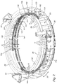
Fig. 2 is a schematic perspective view of an auxiliary device according to an embodiment of the invention; -
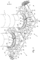
Fig. 3 is a schematic top view of the embodiment of the auxiliary device according to the invention shown infigure 2 ; -
Fig. 4 is a schematic perspective view of a part of an auxiliary device according to an embodiment of the invention in retracted position; -
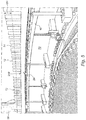
Fig. 5 is a schematic perspective view of the part of the auxiliary device shown infigure 4 in an extended position; and -
Fig. 6 is a schematic perspective detail view of an auxiliary device according to an embodiment of the invention. - Referring to
figure 1 , twosupport structures 2 connected to thedeck 4 of an installation vessel (not further shown) are shown for seafastening of twowind turbine masts 3.Support structures 2 are for instance secured todeck 4 by means of a welded connection. Eachsupport structure 2 is embodied as a lattice structure reinforced withshores 20 and comprising a series ofside plates 21 arranged in a square, between which are arranged strengtheningpartitions 22 which run radially inward and support a centrallydisposed seafastening ring 23. - Secured to a connecting
flange 24 of eachseafastening ring 23 using a large number of bolts is a corresponding connectingflange 34 of awind turbine mast 3. Awind turbine 3 anchored to asupport structure 2 thus extends substantially in adirection 30 perpendicularly of the plane of deck 5. Connectingflanges wind turbine 3 with suitable lifting gear, moving it in the direction ofsupport structure 2 and lowering it onto this structure. Arranged onseafastening ring 23 in aperipheral direction 25 of connectingflange 24 are threeguide plates 26 which facilitate the moving toward each other of connectingflanges - Referring to
figures 2 and3 , an embodiment of anauxiliary device 1 according to the invention is shown. In the shown embodimentauxiliary device 1 comprises four support bodies 10 (10a, 10b), a pair (10a, 10b) of which is placed almost against each other, as can be seen clearly in the top view offigure 3 . The foursupport bodies 10 take the form of a circle segment spanning a peripheral angle of about 60° for the twosupport bodies 10a, and for the twoother support bodies 10b an angle of about 80°.Support bodies 10 are received inseafastening ring 23 such that they substantially overlap with connectingflange 24 ofseafastening ring 23. - A large number of bolt holes 28 distributed along the
peripheral direction 25 is received in connectingflange 24 ofseafastening ring 23. Eachsupport body 10 is provided with a number of receivingpositions 11, likewise distributed alongperipheral direction 25, for abolt 12. The distribution of receivingpositions 11 is such that receivingpositions 11 can be aligned withbolt holes 28 and with corresponding bolt holes in the connectingflange 34 ofwind turbine mast 3 to be arranged against connectingflange 24. - This alignment can be achieved inter alia by connecting
support bodies 10 to theseafastening ring 23 ofwind turbine mast 3 by arranging moving means, welded onto an inner wall ofseafastening ring 23, in the form of two gear transmissions 13 (per support body 10) at determined positions inperipheral direction 25. According tofigure 4 , the showngear transmissions 13 comprise a second part in the form of abox beam 130 welded to the inner wall, a first part in the form of agear rack 131 which runs in vertical direction to a position againstsupport body 10 and is connected thereto, and agearbox 132 in which is received a gear (not visible) driven with thecrank 133. By rotation ofcrank 133 thesupport body 10 can be moved up and downward in vertical direction relative to thebox beam 130 welded toseafastening ring 23. This movement can of course also be made possible in other manner, for instance under the influence of an electrically, pneumatically and/or hydraulically generated force, for instance with hydraulic piston cylinders. - In order to guide the up and downward movement each
support body 10 is further connected with three guide means 14 for therelevant support body 10 to the inner wall ofseafastening ring 23. According tofigure 4 , the shown guide means 14 comprise abox beam 140 welded to the inner wall and having an opening through which a vertically directedguide rod 141, welded to a side surface ofsupport body 10, can be moved. Eachguide rod 141 is secured on a lower side to a bottom part ofseafastening ring 23. During the up and downward movement of asupport body 10guide rod 141 moves relative tobox beam 140 and in this way keeps receivingpositions 11 aligned with the corresponding bolt holes 28 in the connecting flanges (24, 34) to be placed against each other. - In order to enable a number of
bolts 12 to be placed through bolt holes 28 simultaneously, a large number ofbolts 12 is first arranged in receivingpositions 11. The support bodies are here in a relatively low position, such as the position shown infigure 4 .Support bodies 10 are preferably brought to a height wherein, although situated with a part thereof in bolt holes 28,bolts 12 do not rise above anupper surface 240 of connectingflange 24. - A
wind turbine mast 3 is then taken up with a suitable lifting crane and carried with a connectingflange 34 to a position against connectingflange 24 ofseafastening ring 23, until theupper surface 240 of connectingflange 24 and a lower surface of connectingflange 34 ofwind turbine mast 3 lie against each other. The aligning of bolt holes 28 with corresponding bolt holes in connectingflange 34 ofwind turbine mast 3 can be facilitated by pins 241 (seefigure 2 ) arranged on connectingflange 24. - The
support bodies 10 provided withbolts 12 are then moved upward by rotation ofcranks 133, i.e. in the direction of the mutually aligned connectingflanges support bodies 10 is continued until thebolts 12 arranged in receivingpositions 11 protrude substantially simultaneously through bolt holes 28 and through the corresponding bolt holes in connectingflange 34. This state is shown schematically infigure 5 , in which connectingflange 34 ofwind turbine mast 3 is shown with a broken line. In order to eventually realize the connection between the two connecting flanges (24, 34) the protrudingparts 120 are each provided with a counter-nut (not shown). - With the invented auxiliary device 1 a large number of
bolts 12 can be collectively arranged through bolt holes per support body. A large number can indicate any number, although the advantages of the invention become most clearly manifest when the number of bolts per support body 10 (or the number of receiving positions 11) is greater than 5, more preferably greater than 10, still more preferably greater than 15, still more preferably greater than 20, still more preferably greater than 40, still more preferably greater than 80, and most preferably greater than 100. An upper limit to the number of bolts per support body can in principle be determined only by practical conditions, such as for instance the overall weight of the support body with bolts, the dimensions of the connecting flanges, and so on. - The invention is not limited to the embodiments shown in the figures, and many variants thereof are possible within the scope of protection of the appended claims.
Claims (14)
- Auxiliary device for realizing a bolt connection between connecting flanges, placed against each other, of a first and a second structure, comprising a support body provided with a number of receiving positions for a bolt, wherein the receiving positions are aligned with corresponding bolt holes in the connecting flanges to be placed against each other, and wherein the auxiliary device further comprises moving means for moving the support body toward the connecting flanges which are arranged against each other so that a number of bolts arranged in the receiving positions are collectively arranged through the bolt holes, wherein the support body is movably connected via the moving means to the first structure, and wherein a first part of the moving means, which is connected to the support body, can be moved relative to a second part of the moving means, which is connected to the first structure, under the influence of a mechanically, electrically, pneumatically and/or hydraulically generated force.
- Auxiliary device according to claim 1, wherein the moving means comprise a gear transmission.
- Auxiliary device according to any one of the foregoing claims, further comprising guide means for keeping the receiving positions aligned, during movement of the support body, with the corresponding bolt holes in the connecting flanges to be placed against each other.
- Auxiliary device according to any one of the foregoing claims, wherein the support body takes substantially the form of a circle segment for co-action with substantially circular connecting flanges.
- Auxiliary device according to any one of the foregoing claims, wherein the support body extends substantially in a plane and the receiving positions are configured to receive a bolt protruding from the plane, more preferably a bolt running perpendicularly of the plane.
- Auxiliary device according to any one of the foregoing claims, wherein the first structure comprises a support structure for a wind turbine mast and the second structure a wind turbine mast.
- Auxiliary device according to claim 6, wherein the support structure is connected to the deck of a vessel.
- Method for realizing a bolt connection between connecting flanges, placed against each other, of a first and a second structure, comprising of providing an auxiliary device according to any one of the foregoing claims, placing connecting flanges of the first and second structure against each other, aligning the receiving positions of the support body with corresponding bolt holes in the connecting flanges placed against each other, and moving the support body toward the connecting flanges, arranged against each other, with the moving means, so that a number of bolts arranged in the receiving positions is collectively arranged through the bolt holes, wherein the support body is movably connected via the moving means to the first structure, and wherein a first part of the moving means, which is connected to the support body, is moved relative to a second part of the moving means, which is connected to the first structure, under the influence of a mechanically, electrically, pneumatically and/or hydraulically generated force.
- Method according to claim 8, wherein the first part of the moving means, which is connected to the support body, is moved relative to the second part of the moving means by means of a gear transmission.
- Method according to any one of the claims 8-9, wherein during movement of the support body the receiving positions are kept aligned with the corresponding bolt holes in the connecting flanges, which are placed against each other, using guide means.
- Method according to any one of the claims 8-10, wherein the support body takes substantially the form of a circle segment for co-action with substantially circular connecting flanges.
- Method according to any one of the claims 8-11, wherein the support body extends substantially in a plane and a bolt protruding from the plane, more preferably a bolt running perpendicularly of the plane, is received in the receiving positions.
- Method according to any one of the claims 8-12, wherein the first structure comprises a support structure for a wind turbine mast, and the second structure a wind turbine mast.
- Method according to claim 13, wherein the support structure is connected to the deck of a vessel.
Applications Claiming Priority (1)
| Application Number | Priority Date | Filing Date | Title |
|---|---|---|---|
| BE2018/5629A BE1025747B1 (en) | 2018-09-13 | 2018-09-13 | Auxiliary device and method for establishing a bolt connection between connecting flanges of a first and a second construction |
Publications (3)
| Publication Number | Publication Date |
|---|---|
| EP3623645A1 true EP3623645A1 (en) | 2020-03-18 |
| EP3623645C0 EP3623645C0 (en) | 2024-06-19 |
| EP3623645B1 EP3623645B1 (en) | 2024-06-19 |
Family
ID=63762146
Family Applications (1)
| Application Number | Title | Priority Date | Filing Date |
|---|---|---|---|
| EP19187096.3A Active EP3623645B1 (en) | 2018-09-13 | 2019-07-18 | Support structure for a wind turbine mast and method for realizing a bolt connection between connecting flanges of a wind turbine mast and a support structure for a wind turbine mast |
Country Status (4)
| Country | Link |
|---|---|
| US (1) | US10920443B2 (en) |
| EP (1) | EP3623645B1 (en) |
| BE (1) | BE1025747B1 (en) |
| TW (1) | TWI831832B (en) |
Cited By (2)
| Publication number | Priority date | Publication date | Assignee | Title |
|---|---|---|---|---|
| WO2021122289A1 (en) * | 2019-12-17 | 2021-06-24 | Vestas Offshore Wind A/S | A kit for positioning bolts in a flange connection |
| WO2025223626A1 (en) * | 2024-04-22 | 2025-10-30 | Vestas Wind Systems A/S | A method for seafastening a wind turbine component |
Families Citing this family (9)
| Publication number | Priority date | Publication date | Assignee | Title |
|---|---|---|---|---|
| WO2020035803A1 (en) * | 2018-08-14 | 2020-02-20 | Lamprell Energy Ltd. | Grillage for use as a foundation for a wind motor |
| CN114151150B (en) * | 2020-09-07 | 2023-07-25 | 中国航发商用航空发动机有限责任公司 | Turbine outer ring connection assembly, gas turbine engine and connection method |
| NO346610B1 (en) | 2020-12-11 | 2022-10-31 | Nekkar Asa | Apparatus for and method of installing a wind turbine |
| NO346882B1 (en) * | 2021-07-07 | 2023-02-13 | Nekkar Asa | Wind turbine tower installation apparatus, wind turbine support tower and method |
| US12577942B2 (en) | 2021-09-16 | 2026-03-17 | Crowley New Energy, Inc. | Methods of securing a vessel during transportation, off-loading, and installation of wind turbine components |
| CN113883134B (en) * | 2021-09-29 | 2023-03-28 | 东风本田汽车有限公司 | Part positioning and connecting device and positioning and connecting method |
| WO2023175566A1 (en) * | 2022-03-17 | 2023-09-21 | Rute Foundation Systems, Inc. | Post-tensioned wind turbine foundation |
| CN116084760B (en) * | 2022-12-23 | 2024-02-13 | 国网安徽省电力有限公司 | Single-column steel pipe pole high-altitude auxiliary docking device |
| CN119641109B (en) * | 2025-02-13 | 2025-04-18 | 湖南中天建设集团股份有限公司 | Large-span steel beam connection auxiliary device and large-span steel beam connection method |
Citations (8)
| Publication number | Priority date | Publication date | Assignee | Title |
|---|---|---|---|---|
| US4052045A (en) * | 1976-07-29 | 1977-10-04 | Billy Joe Shaddix | Alignment of flanges |
| US5466105A (en) * | 1994-06-09 | 1995-11-14 | Westinghouse Air Brake Company | Fastener assembly for installing valve devices and the like |
| US5632583A (en) * | 1995-07-18 | 1997-05-27 | Schneider; William A. | Split bolt ring |
| US6439807B1 (en) * | 1997-04-24 | 2002-08-27 | Allseas Group S.A. | Method and apparatus for underwater connection of pipe pieces and bolt therefor |
| WO2005090800A1 (en) * | 2004-03-12 | 2005-09-29 | Gkn Driveline North America, Inc. | Bolt assembly |
| EP2615315A1 (en) * | 2012-01-12 | 2013-07-17 | Rolls-Royce plc | Retaining bracket for threaded fasteners and a retaining assembly |
| EP2636899A1 (en) * | 2012-03-06 | 2013-09-11 | Siemens Aktiengesellschaft | Tower base module with segmented base flange |
| WO2017168176A1 (en) * | 2016-04-01 | 2017-10-05 | Steadfast Engineering Limited | Apparatus for use in forming a bolted connection subsea |
Family Cites Families (29)
| Publication number | Priority date | Publication date | Assignee | Title |
|---|---|---|---|---|
| US2327869A (en) * | 1942-07-02 | 1943-08-24 | Dean W Carlson | Roof and its support |
| US5533835A (en) * | 1995-02-06 | 1996-07-09 | Angelette; A. M. | Railroad crossing signal foundation and method of producing and erecting the same |
| US5839239A (en) * | 1996-04-04 | 1998-11-24 | Jang; Byung K. | Apparatus and method for building construction |
| US5800094A (en) * | 1997-02-05 | 1998-09-01 | Jones; Robert L. | Apparatus for lifting and supporting structures |
| JPH11182759A (en) | 1997-12-17 | 1999-07-06 | Kawasaki Heavy Ind Ltd | Flange fastening device |
| US6079905A (en) * | 1998-12-15 | 2000-06-27 | Richard D. Ruiz, Llc | Bracket assembly for lifting and supporting a foundation |
| US6503024B2 (en) * | 2000-03-06 | 2003-01-07 | Stan Rupiper | Concrete foundation pierhead and method of lifting a foundation using a jack assembly |
| US6539685B2 (en) * | 2000-11-28 | 2003-04-01 | Thomas A. Bell | Apparatus and method for lifting sunken foundations |
| DE10226996B4 (en) * | 2001-10-09 | 2014-07-03 | Aloys Wobben | Method for creating a foundation, in particular for a tower of a wind energy plant |
| US7533505B2 (en) * | 2003-01-06 | 2009-05-19 | Henderson Allan P | Pile anchor foundation |
| US7083363B2 (en) * | 2003-05-22 | 2006-08-01 | Jim Nelson Baker | Pier installation system and method |
| US7182316B2 (en) * | 2004-02-05 | 2007-02-27 | Sykes Richard D | Adjustable support bracket |
| US7004683B1 (en) * | 2004-03-26 | 2006-02-28 | Stan Rupiper | Helice pierhead mounting plate and bolt assembly |
| DE102005044989B3 (en) * | 2005-09-21 | 2006-12-14 | Nordex Energy Gmbh | Method of installing foundation for wind power generator involves embedding anchor cage and load divider plate with reinforcement and temporary retaining nuts |
| WO2008036934A2 (en) * | 2006-09-21 | 2008-03-27 | Ahmed Phuly | Partially prefabricated modular foundation system |
| US7744316B2 (en) * | 2007-01-15 | 2010-06-29 | PierTech, LLC | Apparatus for lifting building foundations |
| US20090044482A1 (en) * | 2007-01-30 | 2009-02-19 | Tooman Norman L | Wind turbine installation comprising an apparatus for protection of anchor bolts and method of installation |
| CN201428567Y (en) * | 2009-05-25 | 2010-03-24 | 上海同韵环保能源科技有限公司 | An automatic positioning and centering device for the overall installation of offshore wind turbines |
| US20110138706A1 (en) * | 2010-08-13 | 2011-06-16 | Stefan Voss | Wind turbine anchor element |
| ES2405034B1 (en) * | 2011-11-17 | 2014-04-15 | Acciona Windpower, S.A. | PROCEDURE AND UNIT FOR THE SETTING OF A TOWER FROM AN AIRCRAFT TO A FOUNDATION AND AEROGENERATOR THAT INCLUDES SUCH UNIT |
| DK2667017T3 (en) * | 2012-05-22 | 2015-03-09 | Siemens Ag | Set of a plurality of alignment tools in the field of wind turbines for tower and bottom alignment |
| US8887451B2 (en) * | 2013-03-18 | 2014-11-18 | Gregory Enterprises, Inc. | Pivoting bracket for foundation support system |
| CN205688927U (en) * | 2013-05-10 | 2016-11-16 | 艾瑞电信公司 | Base for a monopole and monopole structure |
| US9003721B1 (en) * | 2013-11-08 | 2015-04-14 | Siemens Aktiengesellschaft | Leveling arrangement for a tower |
| GB201321989D0 (en) * | 2013-12-12 | 2014-01-29 | Claxton Engineering Services Ltd | Connector for joining two tubular members |
| DE102016200160A1 (en) * | 2016-01-08 | 2017-07-13 | Wobben Properties Gmbh | Lifting device for lifting a component of a wind turbine and method for mounting components of a wind turbine |
| EP3195974B1 (en) * | 2016-01-21 | 2022-09-21 | Admede Ab | Robot to move a support platform along a flange connection |
| WO2017133744A1 (en) * | 2016-02-05 | 2017-08-10 | Vestas Wind Systems A/S | Method of replacing anchor bolts in wind turbine foundations |
| JP6656106B2 (en) | 2016-07-21 | 2020-03-04 | 中電プラント株式会社 | Bolt removal jig and bolt removal method |
-
2018
- 2018-09-13 BE BE2018/5629A patent/BE1025747B1/en active IP Right Grant
-
2019
- 2019-07-18 EP EP19187096.3A patent/EP3623645B1/en active Active
- 2019-09-12 US US16/568,713 patent/US10920443B2/en active Active
- 2019-09-16 TW TW108133213A patent/TWI831832B/en active
Patent Citations (8)
| Publication number | Priority date | Publication date | Assignee | Title |
|---|---|---|---|---|
| US4052045A (en) * | 1976-07-29 | 1977-10-04 | Billy Joe Shaddix | Alignment of flanges |
| US5466105A (en) * | 1994-06-09 | 1995-11-14 | Westinghouse Air Brake Company | Fastener assembly for installing valve devices and the like |
| US5632583A (en) * | 1995-07-18 | 1997-05-27 | Schneider; William A. | Split bolt ring |
| US6439807B1 (en) * | 1997-04-24 | 2002-08-27 | Allseas Group S.A. | Method and apparatus for underwater connection of pipe pieces and bolt therefor |
| WO2005090800A1 (en) * | 2004-03-12 | 2005-09-29 | Gkn Driveline North America, Inc. | Bolt assembly |
| EP2615315A1 (en) * | 2012-01-12 | 2013-07-17 | Rolls-Royce plc | Retaining bracket for threaded fasteners and a retaining assembly |
| EP2636899A1 (en) * | 2012-03-06 | 2013-09-11 | Siemens Aktiengesellschaft | Tower base module with segmented base flange |
| WO2017168176A1 (en) * | 2016-04-01 | 2017-10-05 | Steadfast Engineering Limited | Apparatus for use in forming a bolted connection subsea |
Non-Patent Citations (7)
| Title |
|---|
| ANONYMOUS: "A2Sea Installs Last Rentel Turbine", OFFSHOREWIND.BIZ, 3 September 2018 (2018-09-03), pages 1 - 2, XP093375333, Retrieved from the Internet <URL:https://www.offshorewind.biz/2018/09/03/a2sea-installs-last-rentel-turbine/> |
| ANONYMOUS: "GeoSea Finalizes A2SEA Buy", OFFSHOREWIND.BIZ, 4 September 2017 (2017-09-04), pages 1 - 4, XP093375298, Retrieved from the Internet <URL:https://www.offshorewind.biz> |
| ANONYMOUS: "Sea Installer Ready for Rentel Turbine Pick-Up", OFFSHOREWIND.BIZ, 2 May 2018 (2018-05-02), pages 1 - 3, XP093375302, Retrieved from the Internet <URL:https://www.offshorewind.biz/2018/05/02/sea-installer-ready-for-rentel-turbine-pick-up/> |
| ANONYMOUS: "Sea Installer Ticks 33 Turbines Off Rentel List", OFFSHOREWIND.BIZ, 15 August 2018 (2018-08-15), pages 1 - 2, XP093375328, Retrieved from the Internet <URL:https://www.offshorewind.biz/2018/08/15/sea-installer-ticks-33-turbines-off-rentel-list/> |
| ANONYMOUS: "Sea Installer", SHIP-TECHNOLOGY.COM, 1 January 2018 (2018-01-01), pages 1 - 8, XP093375290, Retrieved from the Internet <URL:https://www.ship-technology.com/projects/sea-installer/> |
| ANONYMOUS: "YouTube Data Viewer", DYTLARGE, 1 January 2018 (2018-01-01), pages 1 - 11, XP093375351 |
| DAMEN: "DEME Sea Installer @ Damen Shiprepair Dunkerque", YOUTUBE, 11 June 2018 (2018-06-11), XP093384111, Retrieved from the Internet <URL:https://www.youtube.com/watch?v=7GXd8z9uEpc> |
Cited By (2)
| Publication number | Priority date | Publication date | Assignee | Title |
|---|---|---|---|---|
| WO2021122289A1 (en) * | 2019-12-17 | 2021-06-24 | Vestas Offshore Wind A/S | A kit for positioning bolts in a flange connection |
| WO2025223626A1 (en) * | 2024-04-22 | 2025-10-30 | Vestas Wind Systems A/S | A method for seafastening a wind turbine component |
Also Published As
| Publication number | Publication date |
|---|---|
| US10920443B2 (en) | 2021-02-16 |
| US20200087945A1 (en) | 2020-03-19 |
| TWI831832B (en) | 2024-02-11 |
| TW202014616A (en) | 2020-04-16 |
| EP3623645C0 (en) | 2024-06-19 |
| EP3623645B1 (en) | 2024-06-19 |
| BE1025747B1 (en) | 2019-06-27 |
Similar Documents
| Publication | Publication Date | Title |
|---|---|---|
| US10920443B2 (en) | Auxiliary device and method for realizing a bolt connection between connecting flanges of a first and a second structure | |
| EP3826952B1 (en) | Device and method for upending a tubular element with a longitudinal direction at an outer end | |
| EP3827149B1 (en) | Device and method for upending a tubular element with a longitudinal direction from a support surface at an outer end | |
| EP3826953B1 (en) | Coupling tool for connection to an outer end of a tubular element for upending the element and a related method for this | |
| US10322913B2 (en) | Device and method for placing a rotor blade of a wind turbine | |
| EP2585712B1 (en) | Lifting device and method for positioning of a unwieldy object | |
| EP1499778B1 (en) | Method and vessel for manipulating an offshore construction | |
| JP2021531434A (en) | How to install wind turbines and wind turbines | |
| EP3130796A1 (en) | Wind turbine assembly system and related method | |
| US20120027523A1 (en) | Device and method for assembling a structure at sea | |
| EP3483342B1 (en) | Device and method for arranging a secondary construction on an offshore primary construction | |
| AU2012201136A1 (en) | Device and method for depositing rocks at a defined location on the bottom of a water mass | |
| WO2013093614A1 (en) | Device and method for assembling a structure at sea | |
| EP2256079A1 (en) | Device for assembling a large structure at sea | |
| EP4377521B1 (en) | Device and method for offshore arranging of a wind turbine or components thereof | |
| NO20210161A1 (en) | Crane system for mounting a wind turbine and method for using the crane system | |
| US20240344504A1 (en) | Methods for handling a load, in particular for installing or removing a blade on an offshore wind turbine, and devices for carrying out such methods | |
| EP4540522B1 (en) | Method and blade installation device for installing a blade of an offshore wind turbine | |
| US11131073B2 (en) | Method for foundation of a transformer platform and transformer platform with at least three piles | |
| EP3246471B1 (en) | Device and method for connecting a hollow tubular structure in erected state to a work of a floating device |
Legal Events
| Date | Code | Title | Description |
|---|---|---|---|
| PUAI | Public reference made under article 153(3) epc to a published international application that has entered the european phase |
Free format text: ORIGINAL CODE: 0009012 |
|
| STAA | Information on the status of an ep patent application or granted ep patent |
Free format text: STATUS: THE APPLICATION HAS BEEN PUBLISHED |
|
| AK | Designated contracting states |
Kind code of ref document: A1 Designated state(s): AL AT BE BG CH CY CZ DE DK EE ES FI FR GB GR HR HU IE IS IT LI LT LU LV MC MK MT NL NO PL PT RO RS SE SI SK SM TR |
|
| AX | Request for extension of the european patent |
Extension state: BA ME |
|
| RAP1 | Party data changed (applicant data changed or rights of an application transferred) |
Owner name: DEME OFFSHORE BE N.V. |
|
| STAA | Information on the status of an ep patent application or granted ep patent |
Free format text: STATUS: REQUEST FOR EXAMINATION WAS MADE |
|
| 17P | Request for examination filed |
Effective date: 20200917 |
|
| RBV | Designated contracting states (corrected) |
Designated state(s): AL AT BE BG CH CY CZ DE DK EE ES FI FR GB GR HR HU IE IS IT LI LT LU LV MC MK MT NL NO PL PT RO RS SE SI SK SM TR |
|
| STAA | Information on the status of an ep patent application or granted ep patent |
Free format text: STATUS: EXAMINATION IS IN PROGRESS |
|
| 17Q | First examination report despatched |
Effective date: 20211223 |
|
| GRAP | Despatch of communication of intention to grant a patent |
Free format text: ORIGINAL CODE: EPIDOSNIGR1 |
|
| STAA | Information on the status of an ep patent application or granted ep patent |
Free format text: STATUS: GRANT OF PATENT IS INTENDED |
|
| INTG | Intention to grant announced |
Effective date: 20240111 |
|
| GRAS | Grant fee paid |
Free format text: ORIGINAL CODE: EPIDOSNIGR3 |
|
| GRAA | (expected) grant |
Free format text: ORIGINAL CODE: 0009210 |
|
| STAA | Information on the status of an ep patent application or granted ep patent |
Free format text: STATUS: THE PATENT HAS BEEN GRANTED |
|
| AK | Designated contracting states |
Kind code of ref document: B1 Designated state(s): AL AT BE BG CH CY CZ DE DK EE ES FI FR GB GR HR HU IE IS IT LI LT LU LV MC MK MT NL NO PL PT RO RS SE SI SK SM TR |
|
| RAP3 | Party data changed (applicant data changed or rights of an application transferred) |
Owner name: DEME OFFSHORE BE NV |
|
| REG | Reference to a national code |
Ref country code: GB Ref legal event code: FG4D |
|
| REG | Reference to a national code |
Ref country code: CH Ref legal event code: EP |
|
| REG | Reference to a national code |
Ref country code: DE Ref legal event code: R096 Ref document number: 602019053818 Country of ref document: DE |
|
| U01 | Request for unitary effect filed |
Effective date: 20240712 |
|
| U07 | Unitary effect registered |
Designated state(s): AT BE BG DE DK EE FI FR IT LT LU LV MT NL PT SE SI Effective date: 20240723 |
|
| U20 | Renewal fee for the european patent with unitary effect paid |
Year of fee payment: 6 Effective date: 20240726 |
|
| PG25 | Lapsed in a contracting state [announced via postgrant information from national office to epo] |
Ref country code: HR Free format text: LAPSE BECAUSE OF FAILURE TO SUBMIT A TRANSLATION OF THE DESCRIPTION OR TO PAY THE FEE WITHIN THE PRESCRIBED TIME-LIMIT Effective date: 20240619 |
|
| PG25 | Lapsed in a contracting state [announced via postgrant information from national office to epo] |
Ref country code: GR Free format text: LAPSE BECAUSE OF FAILURE TO SUBMIT A TRANSLATION OF THE DESCRIPTION OR TO PAY THE FEE WITHIN THE PRESCRIBED TIME-LIMIT Effective date: 20240920 |
|
| PG25 | Lapsed in a contracting state [announced via postgrant information from national office to epo] |
Ref country code: NO Free format text: LAPSE BECAUSE OF FAILURE TO SUBMIT A TRANSLATION OF THE DESCRIPTION OR TO PAY THE FEE WITHIN THE PRESCRIBED TIME-LIMIT Effective date: 20240919 Ref country code: HR Free format text: LAPSE BECAUSE OF FAILURE TO SUBMIT A TRANSLATION OF THE DESCRIPTION OR TO PAY THE FEE WITHIN THE PRESCRIBED TIME-LIMIT Effective date: 20240619 Ref country code: GR Free format text: LAPSE BECAUSE OF FAILURE TO SUBMIT A TRANSLATION OF THE DESCRIPTION OR TO PAY THE FEE WITHIN THE PRESCRIBED TIME-LIMIT Effective date: 20240920 Ref country code: RS Free format text: LAPSE BECAUSE OF FAILURE TO SUBMIT A TRANSLATION OF THE DESCRIPTION OR TO PAY THE FEE WITHIN THE PRESCRIBED TIME-LIMIT Effective date: 20240919 |
|
| PG25 | Lapsed in a contracting state [announced via postgrant information from national office to epo] |
Ref country code: PL Free format text: LAPSE BECAUSE OF FAILURE TO SUBMIT A TRANSLATION OF THE DESCRIPTION OR TO PAY THE FEE WITHIN THE PRESCRIBED TIME-LIMIT Effective date: 20240619 |
|
| PG25 | Lapsed in a contracting state [announced via postgrant information from national office to epo] |
Ref country code: IS Free format text: LAPSE BECAUSE OF FAILURE TO SUBMIT A TRANSLATION OF THE DESCRIPTION OR TO PAY THE FEE WITHIN THE PRESCRIBED TIME-LIMIT Effective date: 20241019 |
|
| PG25 | Lapsed in a contracting state [announced via postgrant information from national office to epo] |
Ref country code: CZ Free format text: LAPSE BECAUSE OF FAILURE TO SUBMIT A TRANSLATION OF THE DESCRIPTION OR TO PAY THE FEE WITHIN THE PRESCRIBED TIME-LIMIT Effective date: 20240619 |
|
| PG25 | Lapsed in a contracting state [announced via postgrant information from national office to epo] |
Ref country code: RO Free format text: LAPSE BECAUSE OF FAILURE TO SUBMIT A TRANSLATION OF THE DESCRIPTION OR TO PAY THE FEE WITHIN THE PRESCRIBED TIME-LIMIT Effective date: 20240619 Ref country code: SK Free format text: LAPSE BECAUSE OF FAILURE TO SUBMIT A TRANSLATION OF THE DESCRIPTION OR TO PAY THE FEE WITHIN THE PRESCRIBED TIME-LIMIT Effective date: 20240619 |
|
| PG25 | Lapsed in a contracting state [announced via postgrant information from national office to epo] |
Ref country code: ES Free format text: LAPSE BECAUSE OF FAILURE TO SUBMIT A TRANSLATION OF THE DESCRIPTION OR TO PAY THE FEE WITHIN THE PRESCRIBED TIME-LIMIT Effective date: 20240619 Ref country code: SM Free format text: LAPSE BECAUSE OF FAILURE TO SUBMIT A TRANSLATION OF THE DESCRIPTION OR TO PAY THE FEE WITHIN THE PRESCRIBED TIME-LIMIT Effective date: 20240619 |
|
| PG25 | Lapsed in a contracting state [announced via postgrant information from national office to epo] |
Ref country code: SM Free format text: LAPSE BECAUSE OF FAILURE TO SUBMIT A TRANSLATION OF THE DESCRIPTION OR TO PAY THE FEE WITHIN THE PRESCRIBED TIME-LIMIT Effective date: 20240619 Ref country code: SK Free format text: LAPSE BECAUSE OF FAILURE TO SUBMIT A TRANSLATION OF THE DESCRIPTION OR TO PAY THE FEE WITHIN THE PRESCRIBED TIME-LIMIT Effective date: 20240619 Ref country code: RO Free format text: LAPSE BECAUSE OF FAILURE TO SUBMIT A TRANSLATION OF THE DESCRIPTION OR TO PAY THE FEE WITHIN THE PRESCRIBED TIME-LIMIT Effective date: 20240619 Ref country code: PL Free format text: LAPSE BECAUSE OF FAILURE TO SUBMIT A TRANSLATION OF THE DESCRIPTION OR TO PAY THE FEE WITHIN THE PRESCRIBED TIME-LIMIT Effective date: 20240619 Ref country code: IS Free format text: LAPSE BECAUSE OF FAILURE TO SUBMIT A TRANSLATION OF THE DESCRIPTION OR TO PAY THE FEE WITHIN THE PRESCRIBED TIME-LIMIT Effective date: 20241019 Ref country code: ES Free format text: LAPSE BECAUSE OF FAILURE TO SUBMIT A TRANSLATION OF THE DESCRIPTION OR TO PAY THE FEE WITHIN THE PRESCRIBED TIME-LIMIT Effective date: 20240619 Ref country code: CZ Free format text: LAPSE BECAUSE OF FAILURE TO SUBMIT A TRANSLATION OF THE DESCRIPTION OR TO PAY THE FEE WITHIN THE PRESCRIBED TIME-LIMIT Effective date: 20240619 |
|
| REG | Reference to a national code |
Ref country code: CH Ref legal event code: PL |
|
| PG25 | Lapsed in a contracting state [announced via postgrant information from national office to epo] |
Ref country code: MC Free format text: LAPSE BECAUSE OF FAILURE TO SUBMIT A TRANSLATION OF THE DESCRIPTION OR TO PAY THE FEE WITHIN THE PRESCRIBED TIME-LIMIT Effective date: 20240619 |
|
| REG | Reference to a national code |
Ref country code: DE Ref legal event code: R026 Ref document number: 602019053818 Country of ref document: DE |
|
| PLBI | Opposition filed |
Free format text: ORIGINAL CODE: 0009260 |
|
| PG25 | Lapsed in a contracting state [announced via postgrant information from national office to epo] |
Ref country code: MC Free format text: LAPSE BECAUSE OF FAILURE TO SUBMIT A TRANSLATION OF THE DESCRIPTION OR TO PAY THE FEE WITHIN THE PRESCRIBED TIME-LIMIT Effective date: 20240619 |
|
| PLAX | Notice of opposition and request to file observation + time limit sent |
Free format text: ORIGINAL CODE: EPIDOSNOBS2 |
|
| PG25 | Lapsed in a contracting state [announced via postgrant information from national office to epo] |
Ref country code: CH Free format text: LAPSE BECAUSE OF NON-PAYMENT OF DUE FEES Effective date: 20240731 |
|
| 26 | Opposition filed |
Opponent name: VESTAS WIND SYSTEMS A/S Effective date: 20250319 |
|
| GBPC | Gb: european patent ceased through non-payment of renewal fee |
Effective date: 20240919 |
|
| PG25 | Lapsed in a contracting state [announced via postgrant information from national office to epo] |
Ref country code: GB Free format text: LAPSE BECAUSE OF NON-PAYMENT OF DUE FEES Effective date: 20240919 |
|
| PG25 | Lapsed in a contracting state [announced via postgrant information from national office to epo] |
Ref country code: IE Free format text: LAPSE BECAUSE OF NON-PAYMENT OF DUE FEES Effective date: 20240718 |
|
| PLBB | Reply of patent proprietor to notice(s) of opposition received |
Free format text: ORIGINAL CODE: EPIDOSNOBS3 |
|
| U20 | Renewal fee for the european patent with unitary effect paid |
Year of fee payment: 7 Effective date: 20250715 |
|
| PG25 | Lapsed in a contracting state [announced via postgrant information from national office to epo] |
Ref country code: CY Free format text: LAPSE BECAUSE OF FAILURE TO SUBMIT A TRANSLATION OF THE DESCRIPTION OR TO PAY THE FEE WITHIN THE PRESCRIBED TIME-LIMIT; INVALID AB INITIO Effective date: 20190718 |
|
| PLBD | Termination of opposition procedure: decision despatched |
Free format text: ORIGINAL CODE: EPIDOSNOPC1 |
|
| PLBP | Opposition withdrawn |
Free format text: ORIGINAL CODE: 0009264 |
|
| REG | Reference to a national code |
Ref country code: CH Ref legal event code: L10 Free format text: ST27 STATUS EVENT CODE: U-0-0-L10-L00 (AS PROVIDED BY THE NATIONAL OFFICE) Effective date: 20260211 |
|
| PG25 | Lapsed in a contracting state [announced via postgrant information from national office to epo] |
Ref country code: HU Free format text: LAPSE BECAUSE OF FAILURE TO SUBMIT A TRANSLATION OF THE DESCRIPTION OR TO PAY THE FEE WITHIN THE PRESCRIBED TIME-LIMIT; INVALID AB INITIO Effective date: 20190718 |
|
| PLBM | Termination of opposition procedure: date of legal effect published |
Free format text: ORIGINAL CODE: 0009276 |
|
| REG | Reference to a national code |
Ref country code: CH Ref legal event code: L10 Free format text: ST27 STATUS EVENT CODE: U-0-0-L10-L00 (AS PROVIDED BY THE NATIONAL OFFICE) Effective date: 20260521 |
|
| PG25 | Lapsed in a contracting state [announced via postgrant information from national office to epo] |
Ref country code: TR Free format text: LAPSE BECAUSE OF FAILURE TO SUBMIT A TRANSLATION OF THE DESCRIPTION OR TO PAY THE FEE WITHIN THE PRESCRIBED TIME-LIMIT Effective date: 20240619 |
|
| 27C | Opposition proceedings terminated |
Effective date: 20260202 |