EP3623633A1 - Pump for multiphase fluids - Google Patents
Pump for multiphase fluids Download PDFInfo
- Publication number
- EP3623633A1 EP3623633A1 EP19197704.0A EP19197704A EP3623633A1 EP 3623633 A1 EP3623633 A1 EP 3623633A1 EP 19197704 A EP19197704 A EP 19197704A EP 3623633 A1 EP3623633 A1 EP 3623633A1
- Authority
- EP
- European Patent Office
- Prior art keywords
- pump
- return line
- inlet
- process fluid
- annulus
- Prior art date
- Legal status (The legal status is an assumption and is not a legal conclusion. Google has not performed a legal analysis and makes no representation as to the accuracy of the status listed.)
- Granted
Links
Images


Classifications
-
- F—MECHANICAL ENGINEERING; LIGHTING; HEATING; WEAPONS; BLASTING
- F04—POSITIVE - DISPLACEMENT MACHINES FOR LIQUIDS; PUMPS FOR LIQUIDS OR ELASTIC FLUIDS
- F04C—ROTARY-PISTON, OR OSCILLATING-PISTON, POSITIVE-DISPLACEMENT MACHINES FOR LIQUIDS; ROTARY-PISTON, OR OSCILLATING-PISTON, POSITIVE-DISPLACEMENT PUMPS
- F04C13/00—Adaptations of machines or pumps for special use, e.g. for extremely high pressures
- F04C13/001—Pumps for particular liquids
-
- F—MECHANICAL ENGINEERING; LIGHTING; HEATING; WEAPONS; BLASTING
- F04—POSITIVE - DISPLACEMENT MACHINES FOR LIQUIDS; PUMPS FOR LIQUIDS OR ELASTIC FLUIDS
- F04D—NON-POSITIVE-DISPLACEMENT PUMPS
- F04D3/00—Axial-flow pumps
- F04D3/005—Axial-flow pumps with a conventional single stage rotor
-
- F—MECHANICAL ENGINEERING; LIGHTING; HEATING; WEAPONS; BLASTING
- F04—POSITIVE - DISPLACEMENT MACHINES FOR LIQUIDS; PUMPS FOR LIQUIDS OR ELASTIC FLUIDS
- F04D—NON-POSITIVE-DISPLACEMENT PUMPS
- F04D31/00—Pumping liquids and elastic fluids at the same time
-
- E—FIXED CONSTRUCTIONS
- E21—EARTH OR ROCK DRILLING; MINING
- E21B—EARTH OR ROCK DRILLING; OBTAINING OIL, GAS, WATER, SOLUBLE OR MELTABLE MATERIALS OR A SLURRY OF MINERALS FROM WELLS
- E21B43/00—Methods or apparatus for obtaining oil, gas, water, soluble or meltable materials or a slurry of minerals from wells
- E21B43/12—Methods or apparatus for controlling the flow of the obtained fluid to or in wells
-
- F—MECHANICAL ENGINEERING; LIGHTING; HEATING; WEAPONS; BLASTING
- F04—POSITIVE - DISPLACEMENT MACHINES FOR LIQUIDS; PUMPS FOR LIQUIDS OR ELASTIC FLUIDS
- F04C—ROTARY-PISTON, OR OSCILLATING-PISTON, POSITIVE-DISPLACEMENT MACHINES FOR LIQUIDS; ROTARY-PISTON, OR OSCILLATING-PISTON, POSITIVE-DISPLACEMENT PUMPS
- F04C13/00—Adaptations of machines or pumps for special use, e.g. for extremely high pressures
- F04C13/008—Pumps for submersible use, i.e. down-hole pumping
-
- F—MECHANICAL ENGINEERING; LIGHTING; HEATING; WEAPONS; BLASTING
- F04—POSITIVE - DISPLACEMENT MACHINES FOR LIQUIDS; PUMPS FOR LIQUIDS OR ELASTIC FLUIDS
- F04C—ROTARY-PISTON, OR OSCILLATING-PISTON, POSITIVE-DISPLACEMENT MACHINES FOR LIQUIDS; ROTARY-PISTON, OR OSCILLATING-PISTON, POSITIVE-DISPLACEMENT PUMPS
- F04C15/00—Component parts, details or accessories of machines, pumps or pumping installations, not provided for in groups F04C2/00 - F04C14/00
- F04C15/0057—Driving elements, brakes, couplings, transmission specially adapted for machines or pumps
-
- F—MECHANICAL ENGINEERING; LIGHTING; HEATING; WEAPONS; BLASTING
- F04—POSITIVE - DISPLACEMENT MACHINES FOR LIQUIDS; PUMPS FOR LIQUIDS OR ELASTIC FLUIDS
- F04C—ROTARY-PISTON, OR OSCILLATING-PISTON, POSITIVE-DISPLACEMENT MACHINES FOR LIQUIDS; ROTARY-PISTON, OR OSCILLATING-PISTON, POSITIVE-DISPLACEMENT PUMPS
- F04C15/00—Component parts, details or accessories of machines, pumps or pumping installations, not provided for in groups F04C2/00 - F04C14/00
- F04C15/06—Arrangements for admission or discharge of the working fluid, e.g. constructional features of the inlet or outlet
-
- F—MECHANICAL ENGINEERING; LIGHTING; HEATING; WEAPONS; BLASTING
- F04—POSITIVE - DISPLACEMENT MACHINES FOR LIQUIDS; PUMPS FOR LIQUIDS OR ELASTIC FLUIDS
- F04D—NON-POSITIVE-DISPLACEMENT PUMPS
- F04D1/00—Radial-flow pumps, e.g. centrifugal pumps; Helico-centrifugal pumps
- F04D1/06—Multi-stage pumps
-
- F—MECHANICAL ENGINEERING; LIGHTING; HEATING; WEAPONS; BLASTING
- F04—POSITIVE - DISPLACEMENT MACHINES FOR LIQUIDS; PUMPS FOR LIQUIDS OR ELASTIC FLUIDS
- F04D—NON-POSITIVE-DISPLACEMENT PUMPS
- F04D13/00—Pumping installations or systems
- F04D13/02—Units comprising pumps and their driving means
- F04D13/06—Units comprising pumps and their driving means the pump being electrically driven
- F04D13/08—Units comprising pumps and their driving means the pump being electrically driven for submerged use
- F04D13/086—Units comprising pumps and their driving means the pump being electrically driven for submerged use the pump and drive motor are both submerged
-
- F—MECHANICAL ENGINEERING; LIGHTING; HEATING; WEAPONS; BLASTING
- F04—POSITIVE - DISPLACEMENT MACHINES FOR LIQUIDS; PUMPS FOR LIQUIDS OR ELASTIC FLUIDS
- F04D—NON-POSITIVE-DISPLACEMENT PUMPS
- F04D15/00—Control, e.g. regulation, of pumps, pumping installations or systems
- F04D15/0005—Control, e.g. regulation, of pumps, pumping installations or systems by using valves
-
- F—MECHANICAL ENGINEERING; LIGHTING; HEATING; WEAPONS; BLASTING
- F04—POSITIVE - DISPLACEMENT MACHINES FOR LIQUIDS; PUMPS FOR LIQUIDS OR ELASTIC FLUIDS
- F04D—NON-POSITIVE-DISPLACEMENT PUMPS
- F04D15/00—Control, e.g. regulation, of pumps, pumping installations or systems
- F04D15/0005—Control, e.g. regulation, of pumps, pumping installations or systems by using valves
- F04D15/0011—Control, e.g. regulation, of pumps, pumping installations or systems by using valves by-pass valves
-
- F—MECHANICAL ENGINEERING; LIGHTING; HEATING; WEAPONS; BLASTING
- F04—POSITIVE - DISPLACEMENT MACHINES FOR LIQUIDS; PUMPS FOR LIQUIDS OR ELASTIC FLUIDS
- F04D—NON-POSITIVE-DISPLACEMENT PUMPS
- F04D29/00—Details, component parts, or accessories
- F04D29/18—Rotors
- F04D29/181—Axial flow rotors
-
- F—MECHANICAL ENGINEERING; LIGHTING; HEATING; WEAPONS; BLASTING
- F04—POSITIVE - DISPLACEMENT MACHINES FOR LIQUIDS; PUMPS FOR LIQUIDS OR ELASTIC FLUIDS
- F04D—NON-POSITIVE-DISPLACEMENT PUMPS
- F04D29/00—Details, component parts, or accessories
- F04D29/40—Casings; Connections of working fluid
-
- F—MECHANICAL ENGINEERING; LIGHTING; HEATING; WEAPONS; BLASTING
- F04—POSITIVE - DISPLACEMENT MACHINES FOR LIQUIDS; PUMPS FOR LIQUIDS OR ELASTIC FLUIDS
- F04D—NON-POSITIVE-DISPLACEMENT PUMPS
- F04D29/00—Details, component parts, or accessories
- F04D29/40—Casings; Connections of working fluid
- F04D29/52—Casings; Connections of working fluid for axial pumps
- F04D29/522—Casings; Connections of working fluid for axial pumps especially adapted for elastic fluid pumps
-
- F—MECHANICAL ENGINEERING; LIGHTING; HEATING; WEAPONS; BLASTING
- F04—POSITIVE - DISPLACEMENT MACHINES FOR LIQUIDS; PUMPS FOR LIQUIDS OR ELASTIC FLUIDS
- F04D—NON-POSITIVE-DISPLACEMENT PUMPS
- F04D9/00—Priming; Preventing vapour lock
- F04D9/004—Priming of not self-priming pumps
- F04D9/005—Priming of not self-priming pumps by adducting or recycling liquid
-
- F—MECHANICAL ENGINEERING; LIGHTING; HEATING; WEAPONS; BLASTING
- F04—POSITIVE - DISPLACEMENT MACHINES FOR LIQUIDS; PUMPS FOR LIQUIDS OR ELASTIC FLUIDS
- F04C—ROTARY-PISTON, OR OSCILLATING-PISTON, POSITIVE-DISPLACEMENT MACHINES FOR LIQUIDS; ROTARY-PISTON, OR OSCILLATING-PISTON, POSITIVE-DISPLACEMENT PUMPS
- F04C2210/00—Fluid
- F04C2210/24—Fluid mixed, e.g. two-phase fluid
-
- F—MECHANICAL ENGINEERING; LIGHTING; HEATING; WEAPONS; BLASTING
- F05—INDEXING SCHEMES RELATING TO ENGINES OR PUMPS IN VARIOUS SUBCLASSES OF CLASSES F01-F04
- F05B—INDEXING SCHEME RELATING TO WIND, SPRING, WEIGHT, INERTIA OR LIKE MOTORS, TO MACHINES OR ENGINES FOR LIQUIDS COVERED BY SUBCLASSES F03B, F03D AND F03G
- F05B2210/00—Working fluid
- F05B2210/10—Kind or type
- F05B2210/13—Kind or type mixed, e.g. two-phase fluid
Definitions
- the pump In order to protect the pump from operating below the minimum flow of the operating range the pump is designed for several pump protection strategies are known in the art, for example, to provide a recycle line or a return line to artificially increase the volumetric flow at the pump inlet.
- This return line branches off downstream of the pump outlet and leads back to the pump inlet for recycling a part of the process fluid from the high pressure side downstream of the pump outlet back to the suction side or the inlet of the pump at the low pressure side.
- the return line may be connected to the piping downstream of the pump outlet by a T-piece or any other suited branch off device.
- the return line comprises a valve for opening or closing the return line.
- the liquid extraction unit is for example a static separation device, which tries to separate the liquid out of the multiphase fluid, so that only or mainly the liquid phase of the multiphase fluid is returned to the suction side.
- the liquid extraction unit is not really capable of handling the wide range of operational points, e.g. the strong variations in the GVF. It might be that the liquid extraction unit has a very good efficiency at a certain operating point but when moving away from said operating point the performance of the liquid extraction unit rapidly drops off. It might even be that the liquid extraction unit functions as a gas extraction unit at some operating points. Therefore the solution with the liquid extraction unit is not really satisfying in praxis.
- the process fluid entering the return line is very homogeneous.
- the pump rotor acting on the process fluid creates a very homogeneous mixture of the different phases of the process fluid.
- the gas phase is uniformly distributed in the liquid phase.
- the thoroughly mixed and homogenized process fluid entering the return line has the advantage that a sufficiently high return flow to the low pressure side and to the pump inlet may be achieved thus preventing the pump from operating below the minimum flow that is required for a safe and efficient pump operation.
- the homogenized process fluid in the discharge annulus has to flow through the pump outlet and additional piping prior to entering the return line.
- Such separating devices which can be optionally provided in the multiphase pump according to the invention, are for example disclosed in EP-A-2 626 564 or in EP-A-2 626 563 . These separating devices are co-rotating with the pump rotor to separate solids, e.g. sand, from the process fluid by means of centrifugal forces.
- the outlet of the return line is in fluid communication with the inlet annulus.
- the discharge annulus is in fluid communication with the inlet annulus by means of the return line, so that the process fluid may be directly recycled from the discharge annulus to the inlet annulus, when the return line is open.
- a buffer tank is provided between the discharge annulus and the inlet annulus so that the process fluid recycled through the return line first enters the buffer tank and is then supplied from the buffer tank to the low pressure side of the pump for entering the inlet annulus.
- the outlet of the return line and the pump inlet are disposed in a spaced relationship at the inlet annulus.
- the outlet of the return line is a different opening at the inlet annulus than the pump inlet.
- the return line directly couples the discharge annulus with the inlet annulus, i.e. beside the control valve for opening and closing the return line there is no other device arranged in the return line.
- the return line is for example a single pipe directly connecting the discharge annulus with the inlet annulus.
- the multiphase pump is designed for installation on the sea ground.
- the multiphase pump 1 is designed and adapted for being used as a subsea pump in the oil and gas industry.
- the multiphase pump 1 is configured for installation on the sea ground, i.e. for use beneath the water-surface, in particular down to a depth of 100 m, down to 500 m or even down to more than 1000 m beneath the water-surface of the sea.
- the multiphase process fluid is typically a hydrocarbons containing mixture that has to be pumped from an oilfield for example to a processing unit beneath or on the water-surface or on the shore.
- the multiphase mixture constituting the process fluid to be conveyed can include a liquid phase, a gaseous phase and a solid phase, wherein the liquid phase can include crude oil, seawater and chemicals, the gas phase can include methane, natural gas or the like and the solid phase can include sand, sludge and smaller stones without the multiphase pump 1 being damaged on the pumping of the multiphase mixture.
- the invention is not restricted to this specific example but is related to multiphase pumps in general.
- the invention may be used in a lot of different applications, especially in such applications where the multiphase pump 1 is installed at locations which are difficult to access.
- the shaft 71 of the pump rotor 7 is operatively connected to a drive unit 8, which might be a separate unit located outside the housing 2 of the pump, or which might be integrated into the housing 2.
- a drive unit 8 is usually arranged inside the housing 2.
- the pump rotor 7 is driven during operation of the pump 1 for a rotation about the axial direction A that is defined by the longitudinal axis of the pump rotor 7.
- the inlet 91 of the return line 9 opens into the discharge annulus 6, so that the process fluid may directly enter the inlet 91 of the return line 9 from the discharge annulus 6.
- the inlet 91 of the return line 9 and the pump outlet 4 are disposed in a spaced relationship at the discharge annulus 6.
- the discharge annulus 6 is an annular chamber.
- the inlet 91 of the return line 9 and the pump outlet 4 are arranged diametrically opposed at the discharge annulus 6.
- the distance between the inlet 91 of the return line 9 and the pump outlet 4 at the discharge annulus 6 may be different from 180° when viewed in the circumferential direction of the discharge annulus 6.
- the opening of the inlet 91 into the discharge annulus 6 is a different opening than the opening of the pump outlet 4 into the discharge annulus 6.
- the distance between the outlet 92 of the return line 9 and the pump inlet 3 at the inlet annulus 5 may be different from 180° when viewed in the circumferential direction of the inlet annulus 5.
- the opening of the outlet 92 into the inlet annulus 5 is a different opening than the opening of the pump inlet 3 into the inlet annulus 5.
- the return line 9 is designed as a pipe connecting the discharge annulus 6 with the inlet annulus 5.
- the return line 9 is designed as an external pipe and arranged at the outside of the housing 2.
- the return line 9 is fixed to the housing 2 by means of a first flange connection 94 connecting the inlet 91 of the return line 9 with the discharge annulus 6, and by means of a second flange connection 95 connecting the outlet 92 of the return line 9 with the inlet annulus 5.
- the return line 9 is designed as a pipe having the shortest length that is possible or technically reasonable when considering constructional or structural aspects. Ideally, the length of the pipe constituting the return line is essentially the same as the distance between the discharge annulus 6 and the inlet annulus 5. In practice, the return line 9 is somewhat longer than the distance between the discharge annulus 6 and the inlet annulus 5 due to constructional reasons. It is preferred that the return line 9 has a length which is at most two times and particularly preferred at most 1.5 times the distance between the pump inlet 3 and the pump outlet 4. The short and compact design of the return line 9 has the advantage that the pressure loss caused by friction losses in the return line 9 is very low.
- the short length of the return line 9 reduces any separation effects in the recycled process fluid, such as phase separation, stratification or slug generation. Furthermore, by the short length of the return line 9 considerable temperature variations between the recycled process fluid and the main stream of process fluid are avoided. Due to the low pressure losses and the low thermal variations the formation of hydrates, in particular in the return line 9, is prevented
- the return line 9 further comprises the control valve 93 for opening and closing the return line 9.
- the control valve 93 When the control valve 93 is in the open position the fluid communication through the return line 9 is open, so that the process fluid is recycled from the discharge annulus 6 to the low pressure side LP.
- the control valve 93 When the control valve 93 is in the close position the fluid communication through the return line 9 is closed, so that no process fluid is recycled from the discharge annulus 6 to the low pressure side LP.
- the control valve 93 may be designed as a shut-off valve having only an open and a close position or the control valve 93 may be designed as a flow control valve for regulating the flow of the process fluid through the return line 9.
- the control valve 93 may be configured for example as an electrically actuated valve or as a hydraulically actuated valve.
- the hydraulic performance of the pump 1 is monitored.
- the flow generated by the pump is detected, for example by determining the flow of process fluid discharged through the pump outlet 4.
- the flow may be directly measured by means of one or more appropriate sensors or the flow may be determined by means of other operational parameters of the pump 1 which are indicative for or related to the flow generated by the pump 1.
- the return line 9 is partially or fully opened by means of the control valve 93.
- the process fluid is at least partially recycled from the high pressure side HP to the low pressure side LP or the suction side, respectively, of the pump 1.
- the entire flow of process fluid conveyed to the discharge annulus 6 is returned to the inlet annulus 5.
- the volume flow at the pump inlet 4 or through the inlet annulus 5 is increased, whereby the flow through the pump 1 from the inlet annulus 5 to the discharge annulus 6 is increased, which moves the actual operating pump away from the minimum flow condition back towards the best efficiency point.
- the return line 9 can be closed by means of the control valve 93, so that the process fluid is no longer recycled from the discharge annulus 6 to the low pressure side LP of the pump.
- the outlet 92 of the return line 9 is connected to the pump inlet 3.
- the return line 9 is connected to a buffer tank and the buffer tank is connected with the pump inlet 3.
- the process fluid recycled from the discharge annulus 6 is supplied to the buffer tank. From the buffer tank the process fluid is supplied to the pump inlet 3.
- the embodiment shown in Fig. 1 is configured as a vertical pump with the pump rotor 7 extending in the vertical direction.
- the pump rotor 7 is oriented in the direction of gravity and the axial direction A extends vertically.
- the multiphase pump according to the invention may also be designed as a horizontal pump with the pump rotor 7 extending in the horizontal direction, i.e. perpendicular to the direction of gravity.
- Fig. 2 shows a cross-sectional view of a second embodiment of a multiphase pump 1 according to the invention.
- the second embodiment is designed as a horizontal pump 1.
- the multiphase pump 1 is designed as a multistage pump 1, wherein the pump rotor 7 comprises a plurality of impellers 72 arranged in series on the shaft 71.
- the impellers 72 are designed as semi-axial impellers 72. Between adjacent impellers 72 in each case a stationary diffusor 73 is provided for directing the process fluid to the next stage impeller 72.
- the drive unit 8 for rotating the pump rotor 7 is not shown in Fig. 2 .
- Fig. 3 shows a cross-sectional view of a third embodiment of a multiphase pump 1 according to the invention.
- the third embodiment is here designed as a vertical pump.
- the drive unit 8 for rotating the pump rotor 7 is not shown in Fig. 3 .
- the return line 9 is fixedly connected to the housing 2 in a non-detachable manner.
- the return line 9 is for example welded to the housing 2 as indicated by the welding seams 96 in Fig. 3 .
- Fig. 4 shows a cross-sectional view of a fourth embodiment of a multiphase pump 1 according to the invention.
- the fourth embodiment is here designed as a vertical pump.
- the drive unit 8 for rotating the pump rotor 7 is not shown in Fig. 4 .
- the return line 9 is an internal line, i.e. the return line 9 is arranged inside the housing 2 of the multiphase pump 1.
Landscapes
- Engineering & Computer Science (AREA)
- General Engineering & Computer Science (AREA)
- Mechanical Engineering (AREA)
- Life Sciences & Earth Sciences (AREA)
- Mining & Mineral Resources (AREA)
- Geology (AREA)
- Physics & Mathematics (AREA)
- Environmental & Geological Engineering (AREA)
- Fluid Mechanics (AREA)
- Sustainable Development (AREA)
- General Life Sciences & Earth Sciences (AREA)
- Geochemistry & Mineralogy (AREA)
- Structures Of Non-Positive Displacement Pumps (AREA)
- Details And Applications Of Rotary Liquid Pumps (AREA)
- Rotary Pumps (AREA)
Abstract
Description
- The invention relates to a multiphase pump for conveying a multiphase process fluid in accordance with the preamble of the independent claim.
- Multiphase pumps are used in many different industries, where it is necessary to convey a process fluid which comprises a mixture of a plurality of phases, for example a liquid phase and a gaseous phase. An important example is the oil and gas processing industry where multiphase pumps are used for conveying hydrocarbon fluids, for example for extracting the crude oil from the oil field or for transportation of the oil/gas through pipelines or within refineries.
- In view of an efficient exploitation of oil- and gas fields there is nowadays an increasing demand for pumps that may be installed and operated directly on the sea ground in particular down to a depth of 100 m, down to 500 m or even down to more than 1,000 m beneath the water's surface. Needless to say that the design of such pumps is challenging, in particular because these pumps shall operate in a difficult subsea environment for a long time period with as little as possible maintenance and service work. This requires specific measurements to minimize the amount of equipment involved and to optimize the reliability of the pump.
- Fossil fuels are usually not present in pure form in oil fields or gas fields, but as a multiphase mixture which contains liquid components, gas components and possibly also solid components, such as sand. This multiphase mixture of e.g. crude oil, natural gas and chemicals may also contain seawater and a not unsubstantial proportion of sand and has to be pumped from the oil field or gas field. For such a conveying of fossil fuels, multiphase pumps are used which are able to pump a liquid-gas mixture which may also contain solid components, for example sand.
- One of the challenges regarding the design of multiphase pumps is the fact that in many applications the composition of the multiphase process fluid is strongly varying during operation of the pump. For example, during exploitation of an oil field the ratio of the gaseous phase (e.g. natural gas) and the liquid phase (e.g. crude oil) is strongly varying. These variations may occur very sudden and could cause a drop in pump efficiency, vibrations of the pump or other problems. The ratio of the gaseous phase in the multiphase mixture is commonly measured by the dimensionless gas volume fraction (GVF) designating the volume ratio of the gas in the multiphase process fluid. In applications in the oil and gas industry the GVF may vary between 0% and 100%. These strong variations in the composition of the process fluid could cause that the pump is at least temporarily working outside the operating range the pump is designed for. It is a known measure for reducing the large variations in the GVF to provide a buffer tank upstream of the inlet of a multiphase pump. The multiphase process fluid to be pumped by the multiphase pump is first supplied to a buffer tank of suited volume and the outlet of the buffer tank is connected to the inlet of the pump. By this measure the strong variations of the GVF may be damped thereby improving the pump performance. Modern multiphase pumps in the oil and gas industry may handle multiphase process fluids having a GVF of up to 95% or even more.
- However, in some applications it might not be reasonable to provide a buffer tank, e.g. due to technical reasons or due to a lack of available space.
- But even if providing a buffer tank it might be that the variations in the composition of the multiphase process fluid are still as strong that it cannot be ensured that the multiphase pump is always operating within the operating range the pump is designed for. In particular in case of a very high GVF there is a risk that the liquid flow through the pump falls below the minimum flow, at which the pump is operating in a safe, reliable and efficient manner.
- In order to protect the pump from operating below the minimum flow of the operating range the pump is designed for several pump protection strategies are known in the art, for example, to provide a recycle line or a return line to artificially increase the volumetric flow at the pump inlet. This return line branches off downstream of the pump outlet and leads back to the pump inlet for recycling a part of the process fluid from the high pressure side downstream of the pump outlet back to the suction side or the inlet of the pump at the low pressure side. The return line may be connected to the piping downstream of the pump outlet by a T-piece or any other suited branch off device. The return line comprises a valve for opening or closing the return line. Upon detection of a critical operational state, e.g. a flow that is close to the minimum flow of the operating range of the pump, the valve opens the return line, so that a part of the process fluid is recycled to the suction side of the pump. When the flow through the pump increases and moves away from the minimum required flow, the return line is closed by means of the valve, thus preventing a further recycling of the process fluid to the suction side of the pump. The operation and the control of such a return line is described for example in
EP-A-3 037 668 . - The performance of such a recycling method or return line is heavily influenced by the fluid properties, for example the density and miscibility of the fluid phases, the GVF, fluid velocity, shear forces, temperature and pressure as well as other external factors such as pipe layout, recycle line scaling, valve position, control feedback lag and valve control.
- Thus, depending on the actual conditions it might be that the liquid flow through the return line becomes too low to ensure a reliable operation of the pump.
- For improving the performance of such a return line it is a known measure to provide a liquid extraction unit in or upstream of the return line. The liquid extraction unit is for example a static separation device, which tries to separate the liquid out of the multiphase fluid, so that only or mainly the liquid phase of the multiphase fluid is returned to the suction side. However there is the problem that the liquid extraction unit is not really capable of handling the wide range of operational points, e.g. the strong variations in the GVF. It might be that the liquid extraction unit has a very good efficiency at a certain operating point but when moving away from said operating point the performance of the liquid extraction unit rapidly drops off. It might even be that the liquid extraction unit functions as a gas extraction unit at some operating points. Therefore the solution with the liquid extraction unit is not really satisfying in praxis.
- Starting from this state of the art it is therefore an object of the invention to propose an improved multiphase pump for conveying a multiphase process fluid, wherein the multiphase pump is better protected from operating below the minimum flow the pump is designed for. In particular, the pump shall be suited for subsea applications.
- The subject matter of the invention satisfying this object is characterized by the features of the independent claim.
- Thus, according to the invention a multiphase pump is proposed for conveying a multiphase process fluid from a low pressure side to a high pressure side, comprising a housing having a pump inlet and a pump outlet for the process fluid, further comprising an inlet annulus designed for receiving the process fluid from the pump inlet, a discharge annulus designed for discharging the process fluid into the pump outlet, a pump rotor for rotating about an axial direction arranged within the housing, with the pump rotor being designed for conveying the process fluid from the inlet annulus to the outlet annulus, and a return line for returning the process fluid from the high pressure side to the low pressure side, wherein the return line comprises an inlet for receiving the process fluid, an outlet for discharging the process fluid and a control valve for opening and closing the return line, and wherein the inlet of the return line is arranged directly at the discharge annulus.
- By providing the inlet of the return line directly at the outlet annulus the process fluid entering the return line is very homogeneous. The pump rotor acting on the process fluid creates a very homogeneous mixture of the different phases of the process fluid. In particular, the gas phase is uniformly distributed in the liquid phase. The thoroughly mixed and homogenized process fluid entering the return line has the advantage that a sufficiently high return flow to the low pressure side and to the pump inlet may be achieved thus preventing the pump from operating below the minimum flow that is required for a safe and efficient pump operation. In known solutions, where the return line is branched off downstream of the pump outlet the homogenized process fluid in the discharge annulus has to flow through the pump outlet and additional piping prior to entering the return line. This causes adverse effects in the process fluid to be recycled, such as phase separation, stratification or slug generation. All these adverse separation effects are avoided with the multiphase pump according to the invention, because the process fluid is recycled from a location, namely the discharge annulus, where the homogeneity of the process fluid is the highest.
- In addition, due to the homogeneity of the process fluid in the discharge annulus, there is no need for any liquid extraction unit upstream the inlet of the return line or in the return line.
- It has to be noted that the return line with its inlet directly arranged at the discharge annulus recycles the process fluid to the low pressure side before said process fluid may pass through any additional component that is wetted by the process fluid and in which rotating parts, i.e. parts of the pump rotor, interact with stationary parts of the pump. Said components are for example a balance piston or a bearing for the pump rotor, in particular a bearing lubricated by the process fluid or component(s) of the process fluid. Thus, that process fluid, which is directly returned from the discharge annulus to the low pressure side, does not pass any rotational component, such as a balance piston or a bearing, when flowing from the discharge annulus through the return line.
- The arrangement of the inlet of the return line directly at the discharge annulus assures, that thoroughly mixed and homogenized process fluid through normal swirl in the discharge annulus enters the return line. The multiphase pump according to the invention does not require a separate swirl devices or mixing device to ensure that properly mixed and non-separated multiphase process fluid enters the return line. However, the inlet annulus and the discharge annulus may be designed, for example for a specific application, to include swirl devices or other mechanical surfaces to encourage cyclonic or similar effects to further improve the fluid flow conditions into and out of the return line.
- In addition, an integrated cyclonic separating device using tangential or centrifugal forces may be provided in or at the discharge annulus to remove sand or other solid constituents from the process fluid, in order to avoid the recycling of solids to the low pressure side and the inlet annulus, respectively.
- Such separating devices, which can be optionally provided in the multiphase pump according to the invention, are for example disclosed in
EP-A-2 626 564 or inEP-A-2 626 563 . These separating devices are co-rotating with the pump rotor to separate solids, e.g. sand, from the process fluid by means of centrifugal forces. - According to a preferred embodiment, the inlet of the return line and the pump outlet are disposed in a spaced relationship at the discharge annulus. Thus, the inlet of the return line is a different opening at the discharge annulus than the pump outlet.
- Preferably, the outlet of the return line is in fluid communication with the inlet annulus. Thus, the discharge annulus is in fluid communication with the inlet annulus by means of the return line, so that the process fluid may be directly recycled from the discharge annulus to the inlet annulus, when the return line is open.
- Furthermore, it is preferred, that the outlet of the return line is arranged directly at the inlet annulus.
- According to other embodiments it is also possible, that a buffer tank is provided between the discharge annulus and the inlet annulus so that the process fluid recycled through the return line first enters the buffer tank and is then supplied from the buffer tank to the low pressure side of the pump for entering the inlet annulus.
- According to an advantageous measure, the outlet of the return line and the pump inlet are disposed in a spaced relationship at the inlet annulus. Thus, the outlet of the return line is a different opening at the inlet annulus than the pump inlet.
- According to a preferred embodiment the return line directly couples the discharge annulus with the inlet annulus, i.e. beside the control valve for opening and closing the return line there is no other device arranged in the return line. The return line is for example a single pipe directly connecting the discharge annulus with the inlet annulus.
- According to a preferred design the return line is as short as it is reasonably possible. In particular, the return line has a length, which is at most two times, preferably at most 1.5 times, the distance between the pump inlet and the pump outlet. Thus, it is strived for minimizing the length of the return line. Ideally, the length of the return line corresponds essentially to the distance between the discharge annulus and the inlet annulus. However, depending on the respective design or the respective configuration of the pump and depending on how the return line is coupled to the discharge annulus and the inlet annulus, the total length of the return line may be - in practice - somewhat greater than the distance between the discharge annulus and the inlet annulus. According to this preferred design the return line is configured to have the shortest length that is constructively possible or reasonable.
- The short length of the return line has several advantages: By the short length of the return line separation effects such as stratification, phase separation or slug generation in the recycled process fluid in the return line are avoided or at least considerably reduced. In addition, the short length cause only very low pressure losses along the return line resulting from friction losses in the return line. Furthermore, the thermal variance of the process fluid in the return line as compared to the main stream of the process fluid through the pump is very low, for example the temperature of the process fluid in the return line is at least very similar to the temperature of the process fluid conveyed by the pump rotor from the inlet annulus to the discharge annulus. Both the low pressure drop over the return line and the low thermal variance help to prevent the formation of hydrates.
- According to a preferred embodiment the return line is detachably connected with the housing, for example by means of a flange connection.
- In a preferred embodiment the return line is designed as an external pipe arranged at the outside of the housing.
- In another preferred embodiment the return line is arranged inside the housing.
- The multiphase pump according to the invention may be designed as a vertical pump with the pump rotor extending in the vertical direction. Alternatively, the multiphase pump according to the invention may be designed as a horizontal pump with the pump rotor extending perpendicular to the vertical direction, i.e. in horizontal direction.
- According to a preferred configuration the multiphase pump comprises a drive unit operatively connected to the pump rotor for rotating the pump rotor, wherein the drive unit is arranged inside the housing.
- In particular, the multiphase pump may be designed for subsea oil and gas conveyance.
- In a preferred embodiment the multiphase pump is designed for installation on the sea ground.
- Further advantageous measures and embodiments of the invention will become apparent from the dependent claims.
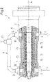
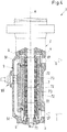
- The invention will be explained in more detail hereinafter with reference to the drawings. There are shown in a schematic representation:
- Fig. 1:
- a cross-sectional view of a first embodiment of a multiphase pump according to the invention,
- Fig.2:
- a cross-sectional view of a second embodiment of a multiphase pump according to the invention,
- Fig. 3:
- a cross-sectional view of a third embodiment of a multiphase pump according to the invention, and
- Fig. 4:
- a cross-sectional view of a fourth embodiment of a multiphase pump according to the invention.
-
Fig. 1 shows a cross-sectional view of an embodiment of a multiphase pump according to the invention which is designated in its entity withreference numeral 1. Themultiphase pump 1 is designed as a centrifugal pump for conveying a multiphase process fluid from a low pressure side LP to a high pressure side HP. Themultiphase pump 1 has ahousing 2 designed as a pressure housing, which is able to withstand the pressure generated by thepump 1 as well as the pressure exerted on thepump 1 by the environment. Thehousing 2 may comprise several housing parts, which are connected to each other to form thehousing 2. - In the following description reference is made by way of example to the important application that the
multiphase pump 1 is designed and adapted for being used as a subsea pump in the oil and gas industry. In particular, themultiphase pump 1 is configured for installation on the sea ground, i.e. for use beneath the water-surface, in particular down to a depth of 100 m, down to 500 m or even down to more than 1000 m beneath the water-surface of the sea. In such applications the multiphase process fluid is typically a hydrocarbons containing mixture that has to be pumped from an oilfield for example to a processing unit beneath or on the water-surface or on the shore. The multiphase mixture constituting the process fluid to be conveyed can include a liquid phase, a gaseous phase and a solid phase, wherein the liquid phase can include crude oil, seawater and chemicals, the gas phase can include methane, natural gas or the like and the solid phase can include sand, sludge and smaller stones without themultiphase pump 1 being damaged on the pumping of the multiphase mixture. - It goes without saying that the invention is not restricted to this specific example but is related to multiphase pumps in general. The invention may be used in a lot of different applications, especially in such applications where the
multiphase pump 1 is installed at locations which are difficult to access. - The
housing 2 of themultiphase pump 1 comprises apump inlet 3 through which the multiphase process fluid enters thepump 1 at the low pressure side LP as indicated by the arrow I, and apump outlet 4 for discharging the process fluid with an increased pressure at the high pressure side HP as indicated by the arrow O. Typically thepump outlet 4 is connected to a pipe or a piping (not shown) for delivering the process fluid to another location. The pressure of the process fluid at thepump outlet 4, i.e. at the high pressure side HP, is typically considerably higher than the pressure of the process fluid at thepump inlet 3, i.e. at the low pressure side LP. A typical value for the difference between the high pressure and the low pressure side is for example 50 to 200 bar. - The
pump 1 further comprises aninlet annulus 5. Thepump inlet 3 opens into theinlet annulus 5, so that theinlet annulus 5 receives the process fluid through thepump inlet 3. Thepump 1 further comprises adischarge annulus 6 for discharging the process fluid into thepump outlet 4, through which the process fluid leaves thepump 1. Thepump outlet 4 opens into thedischarge annulus 6. - The multiphase pump further comprises a
pump rotor 7 for rotating about an axial direction A. In a manner known per se thepump rotor 7 is configured for conveying the process fluid from theinlet annulus 5 at the low pressure side LP to thedischarge annulus 6 at the high pressure side HP. The details of thepump rotor 7 are not shown inFig. 1 . Typically, thepump rotor 7 comprises a shaft 71 (see for exampleFig. 2 ) rotatable about the axial direction A and one impeller 72 (single stage pump) or a plurality of impellers 72 (multistage pump) arranged in series along the axial direction A for conveying the process fluid from theinlet annulus 5 to thedischarge annulus 6 and thereby increasing the pressure of the process fluid. Eachimpeller 72 is fixed to theshaft 71 in a torque-proof manner. Eachimpeller 72 may be designed for example as a radial impeller or as an axial impeller or as a semi-axial impeller. - For rotating the
shaft 71 of thepump rotor 7, theshaft 71 is operatively connected to adrive unit 8, which might be a separate unit located outside thehousing 2 of the pump, or which might be integrated into thehousing 2. For subsea applications thedrive unit 8 is usually arranged inside thehousing 2. - By means of the
drive unit 8 thepump rotor 7 is driven during operation of thepump 1 for a rotation about the axial direction A that is defined by the longitudinal axis of thepump rotor 7. - The
multiphase pump 1 further comprises areturn line 9 for recycling a part of the process fluid from the high pressure side HP to the low pressure side LP. Thereturn line 9 comprises aninlet 91 for receiving the process fluid to be recycled, anoutlet 92 for discharging the process fluid to be recycled, and acontrol valve 93 for opening and closing thereturn line 9. Thecontrol valve 93 may be designed for example as a minimum flow valve, which opens thereturn line 9 when the flow generated by thepump 1 drops below a minimum flow. - According to the invention, the
inlet 91 of thereturn line 9 is arranged directly at thedischarge annulus 6, so that thereturn line 9 receives the process fluid directly from thedischarge annulus 6. The multiphase process fluid in thedischarge annulus 6 is strongly homogenized by the action of thepump rotor 7, which thoroughly mixes at least the liquid and the gaseous phase of the multiphase fluid. - In the embodiment shown in
Fig. 1 theinlet 91 of thereturn line 9 opens into thedischarge annulus 6, so that the process fluid may directly enter theinlet 91 of thereturn line 9 from thedischarge annulus 6. - The
inlet 91 of thereturn line 9 and thepump outlet 4 are disposed in a spaced relationship at thedischarge annulus 6. Typically, thedischarge annulus 6 is an annular chamber. As shown inFig. 1 theinlet 91 of thereturn line 9 and thepump outlet 4 are arranged diametrically opposed at thedischarge annulus 6. - It has to be noted that the distance between the
inlet 91 of thereturn line 9 and thepump outlet 4 at thedischarge annulus 6 may be different from 180° when viewed in the circumferential direction of thedischarge annulus 6. However, the opening of theinlet 91 into thedischarge annulus 6 is a different opening than the opening of thepump outlet 4 into thedischarge annulus 6. - The
outlet 92 of thereturn line 9 is in fluid communication with theinlet annulus 5 of thepump 1. According to the embodiment shown inFig. 1 , theoutlet 92 of thereturn line 9 is arranged directly at theinlet annulus 5. Theoutlet 92 opens into theinlet annulus 5. - The
outlet 92 of thereturn line 9 and thepump inlet 3 are disposed in a spaced relationship at theinlet annulus 5. Typically, theinlet annulus 5 is an annular chamber. As shown inFig. 1 theoutlet 92 of thereturn line 9 and thepump inlet 3 are arranged diametrically opposed at theinlet annulus 5. - It has to be noted that the distance between the
outlet 92 of thereturn line 9 and thepump inlet 3 at theinlet annulus 5 may be different from 180° when viewed in the circumferential direction of theinlet annulus 5. However, the opening of theoutlet 92 into theinlet annulus 5 is a different opening than the opening of thepump inlet 3 into theinlet annulus 5. - The
return line 9 is designed as a pipe connecting thedischarge annulus 6 with theinlet annulus 5. In the first embodiment shown inFig. 1 thereturn line 9 is designed as an external pipe and arranged at the outside of thehousing 2. Thereturn line 9 is fixed to thehousing 2 by means of afirst flange connection 94 connecting theinlet 91 of thereturn line 9 with thedischarge annulus 6, and by means of asecond flange connection 95 connecting theoutlet 92 of thereturn line 9 with theinlet annulus 5. - The
return line 9 is designed as a pipe having the shortest length that is possible or technically reasonable when considering constructional or structural aspects. Ideally, the length of the pipe constituting the return line is essentially the same as the distance between thedischarge annulus 6 and theinlet annulus 5. In practice, thereturn line 9 is somewhat longer than the distance between thedischarge annulus 6 and theinlet annulus 5 due to constructional reasons. It is preferred that thereturn line 9 has a length which is at most two times and particularly preferred at most 1.5 times the distance between thepump inlet 3 and thepump outlet 4. The short and compact design of thereturn line 9 has the advantage that the pressure loss caused by friction losses in thereturn line 9 is very low. In addition the short length of thereturn line 9 reduces any separation effects in the recycled process fluid, such as phase separation, stratification or slug generation. Furthermore, by the short length of thereturn line 9 considerable temperature variations between the recycled process fluid and the main stream of process fluid are avoided. Due to the low pressure losses and the low thermal variations the formation of hydrates, in particular in thereturn line 9, is prevented - As already said, the
return line 9 further comprises thecontrol valve 93 for opening and closing thereturn line 9. When thecontrol valve 93 is in the open position the fluid communication through thereturn line 9 is open, so that the process fluid is recycled from thedischarge annulus 6 to the low pressure side LP. When thecontrol valve 93 is in the close position the fluid communication through thereturn line 9 is closed, so that no process fluid is recycled from thedischarge annulus 6 to the low pressure side LP. Thecontrol valve 93 may be designed as a shut-off valve having only an open and a close position or thecontrol valve 93 may be designed as a flow control valve for regulating the flow of the process fluid through thereturn line 9. - The
control valve 93 may be configured for example as an electrically actuated valve or as a hydraulically actuated valve. - The method for operating the
return line 9, in particular how and when thereturn line 9 is opened or closed by thecontrol valve 93, per se is not particularly relevant for the invention. In principle, each method known in the art for operating areturn line 9 in a pump, in particular in amultiphase pump 1, is suited for operating themultiphase pump 1 according to the invention. As an example reference is made toEP-A-3 037 668 where a method is described for operating a pump having a return line for recycling the process fluid from the high pressure side to the low pressure side or the suction side of the pump. - The basic function of the
return line 9 is to avoid, that themultiphase pump 1 is operating at a flow, which is lower than the minimum flow themultiphase pump 1 is designed for. This minimum flow is a known value, which is given by the design of thepump 1 or the pump installation. - During operation of the
multiphase pump 1 the hydraulic performance of thepump 1 is monitored. For example the flow generated by the pump is detected, for example by determining the flow of process fluid discharged through thepump outlet 4. The flow may be directly measured by means of one or more appropriate sensors or the flow may be determined by means of other operational parameters of thepump 1 which are indicative for or related to the flow generated by thepump 1. - When the flow approaches or reaches the minimum flow the
return line 9 is partially or fully opened by means of thecontrol valve 93. Now, the process fluid is at least partially recycled from the high pressure side HP to the low pressure side LP or the suction side, respectively, of thepump 1. Of course, it is also possible that the entire flow of process fluid conveyed to thedischarge annulus 6 is returned to theinlet annulus 5. - By returning the process fluid from the high pressure side HP to the
pump inlet 3 or to the inlet annulus, respectively, the volume flow at thepump inlet 4 or through theinlet annulus 5 is increased, whereby the flow through thepump 1 from theinlet annulus 5 to thedischarge annulus 6 is increased, which moves the actual operating pump away from the minimum flow condition back towards the best efficiency point. As soon as the flow of process fluid generated by thepump 1 is sufficiently higher than the minimum flow, thereturn line 9 can be closed by means of thecontrol valve 93, so that the process fluid is no longer recycled from thedischarge annulus 6 to the low pressure side LP of the pump. - For recycling the process fluid from the
discharge annulus 6 to the low pressure side LP of the pump it is not necessary to supply the recycled process fluid directly to theinlet annulus 5 through an opening that is different from the orifice of thepump inlet 3 into theinlet annulus 5. - In other embodiment of the
pump 1 theoutlet 92 of thereturn line 9 is connected to thepump inlet 3. - In addition, it is also possible that the
return line 9 is connected to a buffer tank and the buffer tank is connected with thepump inlet 3. In such embodiments the process fluid recycled from thedischarge annulus 6 is supplied to the buffer tank. From the buffer tank the process fluid is supplied to thepump inlet 3. - The embodiment shown in
Fig. 1 is configured as a vertical pump with thepump rotor 7 extending in the vertical direction. During operation of the pump thepump rotor 7 is oriented in the direction of gravity and the axial direction A extends vertically. - It goes without saying that the multiphase pump according to the invention may also be designed as a horizontal pump with the
pump rotor 7 extending in the horizontal direction, i.e. perpendicular to the direction of gravity. - In the following description of further embodiments of the
multiphase pump 1 according to the invention only the differences to the first embodiment are explained in more detail. The explanations with respect to the first embodiment are also valid in the same way or in analogously the same way for the other embodiments. Same reference numerals designate features that have been explained with reference toFig. 1 or functionally equivalent features. In addition, the features explained referring to a specific embodiment may also be implemented in an analogous way in the respective other embodiments. In particular each of the embodiments may be designed as a vertical pump or as a horizontal pump. -
Fig. 2 shows a cross-sectional view of a second embodiment of amultiphase pump 1 according to the invention. The second embodiment is designed as ahorizontal pump 1. Themultiphase pump 1 is designed as amultistage pump 1, wherein thepump rotor 7 comprises a plurality ofimpellers 72 arranged in series on theshaft 71. Theimpellers 72 are designed assemi-axial impellers 72. Betweenadjacent impellers 72 in each case astationary diffusor 73 is provided for directing the process fluid to thenext stage impeller 72. Thedrive unit 8 for rotating thepump rotor 7 is not shown inFig. 2 . -
Fig. 3 shows a cross-sectional view of a third embodiment of amultiphase pump 1 according to the invention. The third embodiment is here designed as a vertical pump. Thedrive unit 8 for rotating thepump rotor 7 is not shown inFig. 3 . - According to the third embodiment the
return line 9 is fixedly connected to thehousing 2 in a non-detachable manner. Thereturn line 9 is for example welded to thehousing 2 as indicated by the welding seams 96 inFig. 3 . -
Fig. 4 shows a cross-sectional view of a fourth embodiment of amultiphase pump 1 according to the invention. The fourth embodiment is here designed as a vertical pump. Thedrive unit 8 for rotating thepump rotor 7 is not shown inFig. 4 . - In the fourth embodiment the
return line 9 is an internal line, i.e. thereturn line 9 is arranged inside thehousing 2 of themultiphase pump 1.
Claims (14)
- A multiphase pump for conveying a multiphase process fluid from a low pressure side (LP) to a high pressure side (HP), comprising a housing (2) having a pump inlet (3) and a pump outlet (4) for the process fluid, further comprising an inlet annulus (5) designed for receiving the process fluid from the pump inlet (4), a discharge annulus (6) designed for discharging the process fluid into the pump outlet (4), a pump rotor (7) for rotating about an axial direction (A) arranged within the housing (2), with the pump rotor (7) being designed for conveying the process fluid from the inlet annulus (5) to the outlet annulus (6), and a return line (9) for returning the process fluid from the high pressure side (HP) to the low pressure side (LP), wherein the return line (9) comprises an inlet (91) for receiving the process fluid, an outlet (92) for discharging the process fluid and a control valve (93) for opening and closing the return line (9), characterized in that the inlet (91) of the return line (9) is arranged directly at the discharge annulus (6).
- A multiphase pump in accordance with claim 1, wherein the inlet (91) of the return line (9) and the pump outlet (4) are disposed in a spaced relationship at the discharge annulus (6).
- A multiphase pump in accordance with anyone of the preceding claims, wherein the outlet (92) of the return line (9) is in fluid communication with the inlet annulus (5).
- A multiphase pump in accordance with anyone of the preceding claims, wherein the outlet (92) of the return line (9) is arranged directly at the inlet annulus (5).
- A multiphase pump in accordance with anyone of the preceding claims, wherein the outlet (92) of the return line (9) and the pump inlet (4) are disposed in a spaced relationship at the inlet annulus (5).
- A multiphase pump in accordance with anyone of the preceding claims, wherein the return line (9) directly couples the discharge annulus (6) with the inlet annulus (5).
- A multiphase pump in accordance with anyone of the preceding claims, wherein the return line (9) has a length, which is at most two times, preferably at most 1.5 times, the distance between the pump inlet (3) and the pump outlet (4).
- A multiphase pump in accordance with anyone of the preceding claims, wherein the return line (9) is detachably connected with the housing (2).
- A multiphase pump in accordance with anyone of the preceding claims, wherein the return line (9) is designed as an external pipe arranged at the outside of the housing (2).
- A multiphase pump in accordance with anyone of claims 1-8, wherein the return line (9) is arranged inside the housing (2).
- A multiphase pump in accordance with anyone of the preceding claims, designed as a vertical pump with the pump rotor (7) extending in the vertical direction.
- A multiphase pump in accordance with any one of the preceding claims, comprising a drive unit (8) operatively connected to the pump rotor (7) for rotating the pump rotor (7), wherein the drive unit (8) is arranged inside the housing (2).
- A multiphase pump in accordance with any one of the preceding claims, designed for subsea oil and gas conveyance.
- A multiphase pump in accordance with any one of the preceding claims, designed for installation on the sea ground.
Applications Claiming Priority (1)
| Application Number | Priority Date | Filing Date | Title |
|---|---|---|---|
| EP18194754 | 2018-09-17 |
Publications (2)
| Publication Number | Publication Date |
|---|---|
| EP3623633A1 true EP3623633A1 (en) | 2020-03-18 |
| EP3623633B1 EP3623633B1 (en) | 2022-11-02 |
Family
ID=63637706
Family Applications (1)
| Application Number | Title | Priority Date | Filing Date |
|---|---|---|---|
| EP19197704.0A Active EP3623633B1 (en) | 2018-09-17 | 2019-09-17 | Pump for multiphase fluids |
Country Status (8)
| Country | Link |
|---|---|
| US (1) | US12135044B2 (en) |
| EP (1) | EP3623633B1 (en) |
| KR (1) | KR20200032638A (en) |
| CN (1) | CN110905863B (en) |
| AU (1) | AU2019219857B2 (en) |
| CA (1) | CA3052441A1 (en) |
| RU (1) | RU2019127660A (en) |
| SG (1) | SG10201907366PA (en) |
Cited By (1)
| Publication number | Priority date | Publication date | Assignee | Title |
|---|---|---|---|---|
| CN119982629A (en) * | 2025-03-31 | 2025-05-13 | 重庆水泵厂有限责任公司 | Design method of low axial force multi-layer supercharged axial flow impeller |
Families Citing this family (5)
| Publication number | Priority date | Publication date | Assignee | Title |
|---|---|---|---|---|
| WO2020072053A1 (en) * | 2018-10-03 | 2020-04-09 | Halliburton Energy Services, Inc. | Electric submersible pump with discharge recycle |
| EP3913226A1 (en) * | 2020-05-18 | 2021-11-24 | Sulzer Management AG | Multiphase pump |
| CN112855614B (en) * | 2021-01-31 | 2022-09-23 | 安徽南方化工泵业有限公司 | Intelligent centrifugal water pump |
| EP4116588A1 (en) | 2021-07-06 | 2023-01-11 | Sulzer Management AG | Multistage centrifugal pump with a recirculation path |
| CN114233633A (en) * | 2022-01-10 | 2022-03-25 | 浙江南元泵业有限公司 | Horizontal single-stage centrifugal pump with pressure boost runner |
Citations (4)
| Publication number | Priority date | Publication date | Assignee | Title |
|---|---|---|---|---|
| EP2626563A2 (en) | 2012-02-10 | 2013-08-14 | Sulzer Pumpen Ag | Pump, recirculating device for a pump and rotor shaft for a pump |
| WO2016077674A1 (en) * | 2014-11-13 | 2016-05-19 | General Electric Company | Subsea fluid processing system with intermediate re-circulation |
| EP3037668A1 (en) | 2014-12-18 | 2016-06-29 | Sulzer Management AG | Operating method for a pump, in particular a multi phase pump as well as a pump |
| US20180073509A1 (en) * | 2016-09-13 | 2018-03-15 | Grundfos Holding A/S | Centrifugal pump assembly |
Family Cites Families (14)
| Publication number | Priority date | Publication date | Assignee | Title |
|---|---|---|---|---|
| US3268155A (en) * | 1964-02-07 | 1966-08-23 | Ingersoll Rand Co | Fluid-flow control system |
| GB1184972A (en) * | 1968-01-02 | 1970-03-18 | Pegg S & Son Ltd | Reversible Impeller Pump |
| US6135723A (en) * | 1999-01-19 | 2000-10-24 | Hatton; Gregory John | Efficient Multistage pump |
| JP3475174B2 (en) * | 2000-02-10 | 2003-12-08 | 東芝テック株式会社 | Electric pump |
| DE50206223D1 (en) | 2001-10-22 | 2006-05-18 | Sulzer Pumpen Ag | Shaft sealing arrangement for a pump for conveying hot fluids |
| US20070177990A1 (en) * | 2006-01-27 | 2007-08-02 | Applied Drives & Systems, Inc. | Centrifugal pump casing relief system |
| CN101265914B (en) * | 2008-05-12 | 2010-06-02 | 杭州小尔机电设计有限公司 | Determining method for two-phase stream diving pump dredging system booster pump station optimal number |
| JP2010031808A (en) * | 2008-07-30 | 2010-02-12 | Shinmaywa Industries Ltd | Casing for pump and pump with the same |
| DE102012015064B4 (en) * | 2012-07-31 | 2018-08-02 | Joh. Heinr. Bornemann Gmbh | Method for operating a multi-phase pump and device thereto |
| NO337108B1 (en) * | 2012-08-14 | 2016-01-25 | Aker Subsea As | Multiphase pressure amplification pump |
| CN102787817B (en) | 2012-09-08 | 2015-02-18 | 东北石油大学 | Comprehensive simulation experimental device of drilling circulation system |
| CN105164423B (en) * | 2012-12-20 | 2018-01-19 | 苏尔寿管理有限公司 | Multiphase pump with separator, wherein process fluid lubricate and cooled down the pump |
| NO338575B1 (en) * | 2014-09-16 | 2016-09-05 | Fmc Kongsberg Subsea As | System for pumping a fluid and process for its operation. |
| US10533578B2 (en) * | 2015-10-12 | 2020-01-14 | Baker Hughes, A Ge Company, Llc | Metal-to-metal sealing for diffusers of an electrical submersible well pump |
-
2019
- 2019-08-08 SG SG10201907366PA patent/SG10201907366PA/en unknown
- 2019-08-19 CA CA3052441A patent/CA3052441A1/en active Pending
- 2019-08-23 AU AU2019219857A patent/AU2019219857B2/en active Active
- 2019-08-30 KR KR1020190107221A patent/KR20200032638A/en not_active Withdrawn
- 2019-09-03 CN CN201910827382.8A patent/CN110905863B/en active Active
- 2019-09-03 US US16/558,953 patent/US12135044B2/en active Active
- 2019-09-03 RU RU2019127660A patent/RU2019127660A/en unknown
- 2019-09-17 EP EP19197704.0A patent/EP3623633B1/en active Active
Patent Citations (5)
| Publication number | Priority date | Publication date | Assignee | Title |
|---|---|---|---|---|
| EP2626563A2 (en) | 2012-02-10 | 2013-08-14 | Sulzer Pumpen Ag | Pump, recirculating device for a pump and rotor shaft for a pump |
| EP2626564A1 (en) | 2012-02-10 | 2013-08-14 | Sulzer Pumpen Ag | Pump, separation device for a pump, and a rotor shaft for a pump |
| WO2016077674A1 (en) * | 2014-11-13 | 2016-05-19 | General Electric Company | Subsea fluid processing system with intermediate re-circulation |
| EP3037668A1 (en) | 2014-12-18 | 2016-06-29 | Sulzer Management AG | Operating method for a pump, in particular a multi phase pump as well as a pump |
| US20180073509A1 (en) * | 2016-09-13 | 2018-03-15 | Grundfos Holding A/S | Centrifugal pump assembly |
Cited By (1)
| Publication number | Priority date | Publication date | Assignee | Title |
|---|---|---|---|---|
| CN119982629A (en) * | 2025-03-31 | 2025-05-13 | 重庆水泵厂有限责任公司 | Design method of low axial force multi-layer supercharged axial flow impeller |
Also Published As
| Publication number | Publication date |
|---|---|
| AU2019219857A1 (en) | 2020-04-02 |
| AU2019219857B2 (en) | 2024-08-15 |
| BR102019017801A2 (en) | 2020-03-31 |
| SG10201907366PA (en) | 2020-04-29 |
| RU2019127660A (en) | 2021-03-03 |
| KR20200032638A (en) | 2020-03-26 |
| EP3623633B1 (en) | 2022-11-02 |
| CN110905863B (en) | 2023-07-07 |
| US12135044B2 (en) | 2024-11-05 |
| CA3052441A1 (en) | 2020-03-17 |
| US20200088201A1 (en) | 2020-03-19 |
| CN110905863A (en) | 2020-03-24 |
Similar Documents
| Publication | Publication Date | Title |
|---|---|---|
| EP3623633B1 (en) | Pump for multiphase fluids | |
| US6171074B1 (en) | Single-shaft compression-pumping device associated with a separator | |
| US9784075B2 (en) | Gas compression system | |
| US7569097B2 (en) | Subsea multiphase pumping systems | |
| US10330122B2 (en) | Operating method for a pump, in particular for a multiphase pump, and pump | |
| EP4031748B1 (en) | Wellhead boosting apparatus and system | |
| WO2018077527A1 (en) | Multiphase pump and method for operating such a pump | |
| EP3832140B1 (en) | Method for operating a pump, in particular a multiphase pump | |
| EP4063665B1 (en) | Multiphase pump | |
| AU2015202860B2 (en) | Combined multi-phase pump and compressor unit and gas compression system | |
| Cooper et al. | Multiphase gas-liquid pumping | |
| Heng et al. | Internal flow visualization and performance characteristics of a disc pump under gas-liquid two-phase flow conditions | |
| BR102019017801B1 (en) | MULTIPHASE PUMP | |
| EP0554937B1 (en) | Liquid ring pump | |
| RU2834626C1 (en) | Method of distributing flows of working media at underwater process plant | |
| Visintainer et al. | Practical Experience with Slurry Systems | |
| Torp | Subsea Multiphase Boosting: Review and Future Applications |
Legal Events
| Date | Code | Title | Description |
|---|---|---|---|
| PUAI | Public reference made under article 153(3) epc to a published international application that has entered the european phase |
Free format text: ORIGINAL CODE: 0009012 |
|
| STAA | Information on the status of an ep patent application or granted ep patent |
Free format text: STATUS: THE APPLICATION HAS BEEN PUBLISHED |
|
| AK | Designated contracting states |
Kind code of ref document: A1 Designated state(s): AL AT BE BG CH CY CZ DE DK EE ES FI FR GB GR HR HU IE IS IT LI LT LU LV MC MK MT NL NO PL PT RO RS SE SI SK SM TR |
|
| STAA | Information on the status of an ep patent application or granted ep patent |
Free format text: STATUS: REQUEST FOR EXAMINATION WAS MADE |
|
| 17P | Request for examination filed |
Effective date: 20200918 |
|
| RBV | Designated contracting states (corrected) |
Designated state(s): AL AT BE BG CH CY CZ DE DK EE ES FI FR GB GR HR HU IE IS IT LI LT LU LV MC MK MT NL NO PL PT RO RS SE SI SK SM TR |
|
| GRAP | Despatch of communication of intention to grant a patent |
Free format text: ORIGINAL CODE: EPIDOSNIGR1 |
|
| STAA | Information on the status of an ep patent application or granted ep patent |
Free format text: STATUS: GRANT OF PATENT IS INTENDED |
|
| INTG | Intention to grant announced |
Effective date: 20220504 |
|
| GRAS | Grant fee paid |
Free format text: ORIGINAL CODE: EPIDOSNIGR3 |
|
| GRAA | (expected) grant |
Free format text: ORIGINAL CODE: 0009210 |
|
| STAA | Information on the status of an ep patent application or granted ep patent |
Free format text: STATUS: THE PATENT HAS BEEN GRANTED |
|
| AK | Designated contracting states |
Kind code of ref document: B1 Designated state(s): AL AT BE BG CH CY CZ DE DK EE ES FI FR GB GR HR HU IE IS IT LI LT LU LV MC MK MT NL NO PL PT RO RS SE SI SK SM TR |
|
| REG | Reference to a national code |
Ref country code: GB Ref legal event code: FG4D |
|
| REG | Reference to a national code |
Ref country code: CH Ref legal event code: EP Ref country code: AT Ref legal event code: REF Ref document number: 1528935 Country of ref document: AT Kind code of ref document: T Effective date: 20221115 |
|
| REG | Reference to a national code |
Ref country code: DE Ref legal event code: R096 Ref document number: 602019021361 Country of ref document: DE |
|
| REG | Reference to a national code |
Ref country code: IE Ref legal event code: FG4D |
|
| REG | Reference to a national code |
Ref country code: NO Ref legal event code: T2 Effective date: 20221102 |
|
| REG | Reference to a national code |
Ref country code: LT Ref legal event code: MG9D |
|
| REG | Reference to a national code |
Ref country code: NL Ref legal event code: MP Effective date: 20221102 |
|
| REG | Reference to a national code |
Ref country code: AT Ref legal event code: MK05 Ref document number: 1528935 Country of ref document: AT Kind code of ref document: T Effective date: 20221102 |
|
| PG25 | Lapsed in a contracting state [announced via postgrant information from national office to epo] |
Ref country code: SE Free format text: LAPSE BECAUSE OF FAILURE TO SUBMIT A TRANSLATION OF THE DESCRIPTION OR TO PAY THE FEE WITHIN THE PRESCRIBED TIME-LIMIT Effective date: 20221102 Ref country code: PT Free format text: LAPSE BECAUSE OF FAILURE TO SUBMIT A TRANSLATION OF THE DESCRIPTION OR TO PAY THE FEE WITHIN THE PRESCRIBED TIME-LIMIT Effective date: 20230302 Ref country code: LT Free format text: LAPSE BECAUSE OF FAILURE TO SUBMIT A TRANSLATION OF THE DESCRIPTION OR TO PAY THE FEE WITHIN THE PRESCRIBED TIME-LIMIT Effective date: 20221102 Ref country code: FI Free format text: LAPSE BECAUSE OF FAILURE TO SUBMIT A TRANSLATION OF THE DESCRIPTION OR TO PAY THE FEE WITHIN THE PRESCRIBED TIME-LIMIT Effective date: 20221102 Ref country code: ES Free format text: LAPSE BECAUSE OF FAILURE TO SUBMIT A TRANSLATION OF THE DESCRIPTION OR TO PAY THE FEE WITHIN THE PRESCRIBED TIME-LIMIT Effective date: 20221102 Ref country code: AT Free format text: LAPSE BECAUSE OF FAILURE TO SUBMIT A TRANSLATION OF THE DESCRIPTION OR TO PAY THE FEE WITHIN THE PRESCRIBED TIME-LIMIT Effective date: 20221102 |
|
| PG25 | Lapsed in a contracting state [announced via postgrant information from national office to epo] |
Ref country code: RS Free format text: LAPSE BECAUSE OF FAILURE TO SUBMIT A TRANSLATION OF THE DESCRIPTION OR TO PAY THE FEE WITHIN THE PRESCRIBED TIME-LIMIT Effective date: 20221102 Ref country code: PL Free format text: LAPSE BECAUSE OF FAILURE TO SUBMIT A TRANSLATION OF THE DESCRIPTION OR TO PAY THE FEE WITHIN THE PRESCRIBED TIME-LIMIT Effective date: 20221102 Ref country code: LV Free format text: LAPSE BECAUSE OF FAILURE TO SUBMIT A TRANSLATION OF THE DESCRIPTION OR TO PAY THE FEE WITHIN THE PRESCRIBED TIME-LIMIT Effective date: 20221102 Ref country code: IS Free format text: LAPSE BECAUSE OF FAILURE TO SUBMIT A TRANSLATION OF THE DESCRIPTION OR TO PAY THE FEE WITHIN THE PRESCRIBED TIME-LIMIT Effective date: 20230302 Ref country code: HR Free format text: LAPSE BECAUSE OF FAILURE TO SUBMIT A TRANSLATION OF THE DESCRIPTION OR TO PAY THE FEE WITHIN THE PRESCRIBED TIME-LIMIT Effective date: 20221102 Ref country code: GR Free format text: LAPSE BECAUSE OF FAILURE TO SUBMIT A TRANSLATION OF THE DESCRIPTION OR TO PAY THE FEE WITHIN THE PRESCRIBED TIME-LIMIT Effective date: 20230203 |
|
| P01 | Opt-out of the competence of the unified patent court (upc) registered |
Effective date: 20230412 |
|
| PG25 | Lapsed in a contracting state [announced via postgrant information from national office to epo] |
Ref country code: NL Free format text: LAPSE BECAUSE OF FAILURE TO SUBMIT A TRANSLATION OF THE DESCRIPTION OR TO PAY THE FEE WITHIN THE PRESCRIBED TIME-LIMIT Effective date: 20221102 |
|
| PG25 | Lapsed in a contracting state [announced via postgrant information from national office to epo] |
Ref country code: SM Free format text: LAPSE BECAUSE OF FAILURE TO SUBMIT A TRANSLATION OF THE DESCRIPTION OR TO PAY THE FEE WITHIN THE PRESCRIBED TIME-LIMIT Effective date: 20221102 Ref country code: RO Free format text: LAPSE BECAUSE OF FAILURE TO SUBMIT A TRANSLATION OF THE DESCRIPTION OR TO PAY THE FEE WITHIN THE PRESCRIBED TIME-LIMIT Effective date: 20221102 Ref country code: EE Free format text: LAPSE BECAUSE OF FAILURE TO SUBMIT A TRANSLATION OF THE DESCRIPTION OR TO PAY THE FEE WITHIN THE PRESCRIBED TIME-LIMIT Effective date: 20221102 Ref country code: DK Free format text: LAPSE BECAUSE OF FAILURE TO SUBMIT A TRANSLATION OF THE DESCRIPTION OR TO PAY THE FEE WITHIN THE PRESCRIBED TIME-LIMIT Effective date: 20221102 Ref country code: CZ Free format text: LAPSE BECAUSE OF FAILURE TO SUBMIT A TRANSLATION OF THE DESCRIPTION OR TO PAY THE FEE WITHIN THE PRESCRIBED TIME-LIMIT Effective date: 20221102 |
|
| REG | Reference to a national code |
Ref country code: DE Ref legal event code: R097 Ref document number: 602019021361 Country of ref document: DE |
|
| PG25 | Lapsed in a contracting state [announced via postgrant information from national office to epo] |
Ref country code: SK Free format text: LAPSE BECAUSE OF FAILURE TO SUBMIT A TRANSLATION OF THE DESCRIPTION OR TO PAY THE FEE WITHIN THE PRESCRIBED TIME-LIMIT Effective date: 20221102 Ref country code: AL Free format text: LAPSE BECAUSE OF FAILURE TO SUBMIT A TRANSLATION OF THE DESCRIPTION OR TO PAY THE FEE WITHIN THE PRESCRIBED TIME-LIMIT Effective date: 20221102 |
|
| PLBE | No opposition filed within time limit |
Free format text: ORIGINAL CODE: 0009261 |
|
| STAA | Information on the status of an ep patent application or granted ep patent |
Free format text: STATUS: NO OPPOSITION FILED WITHIN TIME LIMIT |
|
| 26N | No opposition filed |
Effective date: 20230803 |
|
| PG25 | Lapsed in a contracting state [announced via postgrant information from national office to epo] |
Ref country code: SI Free format text: LAPSE BECAUSE OF FAILURE TO SUBMIT A TRANSLATION OF THE DESCRIPTION OR TO PAY THE FEE WITHIN THE PRESCRIBED TIME-LIMIT Effective date: 20221102 |
|
| REG | Reference to a national code |
Ref country code: CH Ref legal event code: PL |
|
| PG25 | Lapsed in a contracting state [announced via postgrant information from national office to epo] |
Ref country code: LU Free format text: LAPSE BECAUSE OF NON-PAYMENT OF DUE FEES Effective date: 20230917 |
|
| REG | Reference to a national code |
Ref country code: BE Ref legal event code: MM Effective date: 20230930 |
|
| PG25 | Lapsed in a contracting state [announced via postgrant information from national office to epo] |
Ref country code: LU Free format text: LAPSE BECAUSE OF NON-PAYMENT OF DUE FEES Effective date: 20230917 Ref country code: IT Free format text: LAPSE BECAUSE OF FAILURE TO SUBMIT A TRANSLATION OF THE DESCRIPTION OR TO PAY THE FEE WITHIN THE PRESCRIBED TIME-LIMIT Effective date: 20221102 Ref country code: MC Free format text: LAPSE BECAUSE OF FAILURE TO SUBMIT A TRANSLATION OF THE DESCRIPTION OR TO PAY THE FEE WITHIN THE PRESCRIBED TIME-LIMIT Effective date: 20221102 |
|
| REG | Reference to a national code |
Ref country code: IE Ref legal event code: MM4A |
|
| PG25 | Lapsed in a contracting state [announced via postgrant information from national office to epo] |
Ref country code: IE Free format text: LAPSE BECAUSE OF NON-PAYMENT OF DUE FEES Effective date: 20230917 |
|
| PG25 | Lapsed in a contracting state [announced via postgrant information from national office to epo] |
Ref country code: CH Free format text: LAPSE BECAUSE OF NON-PAYMENT OF DUE FEES Effective date: 20230930 |
|
| PG25 | Lapsed in a contracting state [announced via postgrant information from national office to epo] |
Ref country code: IE Free format text: LAPSE BECAUSE OF NON-PAYMENT OF DUE FEES Effective date: 20230917 Ref country code: CH Free format text: LAPSE BECAUSE OF NON-PAYMENT OF DUE FEES Effective date: 20230930 |
|
| PG25 | Lapsed in a contracting state [announced via postgrant information from national office to epo] |
Ref country code: BE Free format text: LAPSE BECAUSE OF NON-PAYMENT OF DUE FEES Effective date: 20230930 |
|
| PG25 | Lapsed in a contracting state [announced via postgrant information from national office to epo] |
Ref country code: BG Free format text: LAPSE BECAUSE OF FAILURE TO SUBMIT A TRANSLATION OF THE DESCRIPTION OR TO PAY THE FEE WITHIN THE PRESCRIBED TIME-LIMIT Effective date: 20221102 |
|
| PG25 | Lapsed in a contracting state [announced via postgrant information from national office to epo] |
Ref country code: BG Free format text: LAPSE BECAUSE OF FAILURE TO SUBMIT A TRANSLATION OF THE DESCRIPTION OR TO PAY THE FEE WITHIN THE PRESCRIBED TIME-LIMIT Effective date: 20221102 |
|
| PG25 | Lapsed in a contracting state [announced via postgrant information from national office to epo] |
Ref country code: CY Free format text: LAPSE BECAUSE OF FAILURE TO SUBMIT A TRANSLATION OF THE DESCRIPTION OR TO PAY THE FEE WITHIN THE PRESCRIBED TIME-LIMIT; INVALID AB INITIO Effective date: 20190917 |
|
| PG25 | Lapsed in a contracting state [announced via postgrant information from national office to epo] |
Ref country code: HU Free format text: LAPSE BECAUSE OF FAILURE TO SUBMIT A TRANSLATION OF THE DESCRIPTION OR TO PAY THE FEE WITHIN THE PRESCRIBED TIME-LIMIT; INVALID AB INITIO Effective date: 20190917 |
|
| PGFP | Annual fee paid to national office [announced via postgrant information from national office to epo] |
Ref country code: DE Payment date: 20250919 Year of fee payment: 7 |
|
| PGFP | Annual fee paid to national office [announced via postgrant information from national office to epo] |
Ref country code: NO Payment date: 20250923 Year of fee payment: 7 |
|
| PGFP | Annual fee paid to national office [announced via postgrant information from national office to epo] |
Ref country code: GB Payment date: 20250919 Year of fee payment: 7 |
|
| PGFP | Annual fee paid to national office [announced via postgrant information from national office to epo] |
Ref country code: FR Payment date: 20250922 Year of fee payment: 7 |
|
| PG25 | Lapsed in a contracting state [announced via postgrant information from national office to epo] |
Ref country code: TR Free format text: LAPSE BECAUSE OF FAILURE TO SUBMIT A TRANSLATION OF THE DESCRIPTION OR TO PAY THE FEE WITHIN THE PRESCRIBED TIME-LIMIT Effective date: 20221102 |