EP3623618A1 - Pompe avec système de va-et-vient à pignon et crémaillère et utilisation d'une telle pompe - Google Patents
Pompe avec système de va-et-vient à pignon et crémaillère et utilisation d'une telle pompe Download PDFInfo
- Publication number
- EP3623618A1 EP3623618A1 EP19196776.9A EP19196776A EP3623618A1 EP 3623618 A1 EP3623618 A1 EP 3623618A1 EP 19196776 A EP19196776 A EP 19196776A EP 3623618 A1 EP3623618 A1 EP 3623618A1
- Authority
- EP
- European Patent Office
- Prior art keywords
- pump
- pinion
- axis
- rack
- piston
- Prior art date
- Legal status (The legal status is an assumption and is not a legal conclusion. Google has not performed a legal analysis and makes no representation as to the accuracy of the status listed.)
- Granted
Links
Images

Classifications
-
- F—MECHANICAL ENGINEERING; LIGHTING; HEATING; WEAPONS; BLASTING
- F04—POSITIVE - DISPLACEMENT MACHINES FOR LIQUIDS; PUMPS FOR LIQUIDS OR ELASTIC FLUIDS
- F04B—POSITIVE-DISPLACEMENT MACHINES FOR LIQUIDS; PUMPS
- F04B9/00—Piston machines or pumps characterised by the driving or driven means to or from their working members
- F04B9/02—Piston machines or pumps characterised by the driving or driven means to or from their working members the means being mechanical
-
- F—MECHANICAL ENGINEERING; LIGHTING; HEATING; WEAPONS; BLASTING
- F04—POSITIVE - DISPLACEMENT MACHINES FOR LIQUIDS; PUMPS FOR LIQUIDS OR ELASTIC FLUIDS
- F04B—POSITIVE-DISPLACEMENT MACHINES FOR LIQUIDS; PUMPS
- F04B17/00—Pumps characterised by combination with, or adaptation to, specific driving engines or motors
- F04B17/03—Pumps characterised by combination with, or adaptation to, specific driving engines or motors driven by electric motors
-
- F—MECHANICAL ENGINEERING; LIGHTING; HEATING; WEAPONS; BLASTING
- F04—POSITIVE - DISPLACEMENT MACHINES FOR LIQUIDS; PUMPS FOR LIQUIDS OR ELASTIC FLUIDS
- F04B—POSITIVE-DISPLACEMENT MACHINES FOR LIQUIDS; PUMPS
- F04B5/00—Machines or pumps with differential-surface pistons
- F04B5/02—Machines or pumps with differential-surface pistons with double-acting pistons
-
- F—MECHANICAL ENGINEERING; LIGHTING; HEATING; WEAPONS; BLASTING
- F04—POSITIVE - DISPLACEMENT MACHINES FOR LIQUIDS; PUMPS FOR LIQUIDS OR ELASTIC FLUIDS
- F04B—POSITIVE-DISPLACEMENT MACHINES FOR LIQUIDS; PUMPS
- F04B53/00—Component parts, details or accessories not provided for in, or of interest apart from, groups F04B1/00 - F04B23/00 or F04B39/00 - F04B47/00
- F04B53/14—Pistons, piston-rods or piston-rod connections
- F04B53/144—Adaptation of piston-rods
- F04B53/146—Piston-rod guiding arrangements
Definitions
- the present invention relates to a pump for a fluid product, the pump being of the type comprising a frame, a piston and a piston drive system for moving the piston relative to the frame in translation in a reciprocating movement along an axis. movement, the drive system comprising an input shaft extending along an axis of rotation, a motor adapted to drive said input shaft in rotation about the axis of rotation relative to the frame, and a system of conversion to convert the rotation of the input shaft around the axis of rotation into a translational movement of the piston.
- fluid product is understood here and hereinafter a product which has a viscosity between 1 mPa.s and 2 kPa.s, this viscosity being for example measured using a Brookfield Plan Cone viscometer in normal temperature and pressure conditions.
- This expression thus includes products in the liquid state, perfectly deformable and with low viscosity, but also products generally qualified as “pasty", more viscous than liquids and having an intermediate state between the liquid state and the solid state .
- the invention also relates to the use of such a pump for pumping a paint or a viscous product, a “viscous product” being defined here and hereinafter as a product having a viscosity of between 3000 and 300000 mPa.s.
- Pumps of the aforementioned type are known and are commonly used for pumping paints and viscous products.
- their motor consists of an electric, or pneumatic, or hydroelectric motor.
- the conversion system of these pumps consists of a ball screw.
- a disadvantage of this solution is that it requires driving a reversal of the direction of rotation of the motor, which requires the use of a relatively expensive motor.
- the ball screw requires an initial setting which complicates the manufacture of the conversion system.
- the ball screw has a very limited life.
- a third known solution consists in using a connecting rod-crank system to convert the rotation of the input shaft into translation of the pivot. This solution makes it possible to produce a reciprocating movement of the piston despite a constant direction of rotation for the engine. However, it has the disadvantage of requiring complex control of the motor rotation speed to maintain a substantially constant speed of the piston in each direction.
- a fourth known solution consists in driving with the input shaft a cam against which the piston shaft is held in abutment. Again, this solution makes it possible to produce a reciprocating movement of the piston while maintaining a constant direction of rotation for the motor. However, it is not entirely satisfactory, since it is necessary to provide a piston return system against the cam which complicates the drive system and reduces the working stroke of the piston.
- An object of the invention is thus to provide a pump whose piston is simply and economically driven by a motor with a constant direction of rotation.
- the invention relates to a pump of the aforementioned type, in which the conversion system comprises a reciprocating system with pinion and rack.
- the invention also relates to the use of the pump defined above to pump a paint, a varnish, a viscous product, or another liquid product.
- the pump 10 shown in the Figure 1 conventionally comprises a frame 12 and a pumping unit 14.
- the pumping unit 14 comprises, in a conventional manner, a cylindrical chamber 16 for receiving the fluid to be pumped, and a piston 18.
- the chamber 16 is integral with the frame 12 and is oriented along an axis AA ′. It is closed at a first axial end by a first wall 20, and at the opposite axial end by a second wall 22.
- the piston 18 is mounted movable in translation inside the chamber 16 along said axis A-A '. It performs a sealed separation between a first part 24 of the chamber 16, which extends from the first wall 20 to the piston 18, and a second part 26 of the chamber 16 which extends from the second wall 22 to to the piston 18. Depending on the position of the piston 18 inside the chamber 16, the volume of each of the first and second parts 24, 26 varies.
- the piston 18 is integral with a shaft 28 oriented parallel to the axis A-A 'and preferably, as shown, substantially coaxial with the axis A-A'.
- This shaft 28 extends through the second wall 22, in which a through orifice 30 is provided for this purpose.
- the pumping unit 14 also comprises a supply of fluid 32 to supply the chamber 16 with fluid, and a fluid discharge 34 to allow the fluid to be discharged from the chamber 16.
- the supply 32 comprises a supply inlet 40 for the connection of a fluid supply pipe (not shown), a first supply branch 42 fluidly connecting said inlet 40 to a first supply orifice 44 formed in the first wall 20, and a first supply non-return valve 46 mounted in the first branch 42 so as to allow the circulation of fluid from the inlet 40 to the orifice 44 by preventing the discharge of fluid from the orifice 44 towards entry 40.
- the evacuation 34 comprises an evacuation outlet 50 for the connection of a fluid evacuation pipe (not shown), a first evacuation branch 52 fluidly connecting said outlet 50 to a first evacuation orifice 54 formed in the first wall 20, and a first evacuation check valve 56 mounted in the first branch 52 so as to allow the circulation of fluid from the orifice 54 towards the outlet 50 while preventing the discharge of fluid from the outlet 50 towards the orifice 54.
- the pumping unit 14 is adapted so that the displacement of the piston 18 from the first wall 20 towards the second wall 22 causes the suction of the fluid product from the inlet 40 in the first part 24 of the chamber 16, and that the displacement of the piston 18 from the second wall 22 towards the first wall 20 causes the fluid product to be discharged from the first part of the chamber 16, towards the outlet 50.
- the pump 10 is a double-acting pump, that is to say that the pumping unit 14 is adapted so that the displacement of the piston 18 from the second wall 22 towards the first wall 20 causes also the aspiration of the fluid product from the inlet 40 in the second part 26 of the chamber 16, and that the displacement of the piston 18 from the first wall 20 towards the second wall 22 also causes the fluid product to be discharged from the second part 26 of room 16, towards exit 50.
- the supply 32 also comprises a second supply branch 58 fluidly connecting the inlet 40 to a second supply orifice 60 formed in the second wall 22, and a second supply non-return valve 62 mounted in the second branch 58 so as to allow the circulation of fluid from the inlet 40 to the orifice 60 by preventing the delivery of fluid from the orifice 60 to the inlet 40.
- the evacuation 34 also comprises a second evacuation branch 64 fluidly connecting the outlet 50 to a second evacuation orifice 66 formed in the second wall 22, and a second evacuation non-return valve 68 mounted in the second branch 64 so as to allow the circulation of fluid from port 66 to outlet 50 by prohibiting the discharge of fluid from outlet 50 to port 66.
- the pumping unit 14 is here constituted by a four ball pump.
- the pumping unit 14 is constituted by a two ball pump.
- the pump 10 also comprises a system 70 for driving the piston 18 to move the piston 18 inside the chamber 16 in translation according to a back-and-forth movement along the axis AA '.
- this drive system 70 comprises an input shaft 72, a motor 74 for driving said input shaft 72 in rotation about its axis relative to the frame 12, and a conversion system 76 for converting the rotation of the input shaft 72 around its axis in translational movement of the piston 18 along the axis AA '.
- the input shaft 72 is elongated along an axis B-B 'orthogonal to the axis A-A'. It is also mounted movable in rotation relative to the frame 12 around this same axis B-B '.
- the input shaft 72 is thus adapted to occupy different angular positions relative to the frame 12, each angular position being defined by an angle between 0 ° and 360 ° relative to a reference position of the shaft 72, a rotation complete of the shaft 72 around the axis BB 'bringing the shaft 72 back to its initial angular position.
- the motor 74 comprises a stator (not shown) secured to the frame 12, and a rotor (not shown) mounted to rotate about its axis relative to the frame 12. Said rotor is kinematically linked to the input shaft 72, typically by means of a reduction gear (not shown), so that the rotation of the rotor causes the rotation of the input shaft 72; as a variant, the rotor constitutes the input shaft 72.
- the motor 74 is typically constituted by an electric motor, for example a brushless motor or an asynchronous motor.
- the conversion system 76 comprises a carriage 80 mounted movable in translation relative to the frame 12 in a direction parallel to the axis AA ′. This carriage 80 is integral with the piston 18, via the shaft 28.
- the carriage 80 has a generally parallelepiped shape.
- the conversion system 76 also includes a guide system 82 for guiding the movement of the carriage 80 relative to the frame 12.
- This guide system 82 here comprises a pair of rails 84 together framing the carriage 80 in a direction orthogonal to the axes A-A 'and B-B', each rail 84 being parallel to the axis A-A '.
- the system 82 also includes, for each rail 84, two rotary rollers 86 mounted on the carriage 80 and making the interface between the carriage 80 and the rail 84, each roller 86 being centered on a proper axis parallel to the axis BB ' and being freely rotatable about this axis relative to the carriage 80.
- each roller 86 is positioned at a respective edge of the carriage 80.
- the conversion system 76 also comprises a conversion device 90 for converting the rotation of the input shaft 72 about its axis BB 'into a reciprocating movement of the carriage 80 and, by this means, of the piston 18 , along the axis A-A '.
- this conversion device 90 consists of a back and forth system with pinion and rack.
- This reciprocating system 90 comprises a half-pinion 92, a first rack 94 able to mesh the half-pinion 92 in a first direction, and a second rack 96 able to mesh the half-pinion 92 in a second direction opposite to the first direction.
- a second rack 96 able to mesh the half-pinion 92 in a second direction opposite to the first direction.
- the half-pinion 92 is mounted movable in rotation relative to the frame 12 around the axis B-B 'and is stationary in translation relative to the frame 12 along the axis A-A'. It is kinematically linked to the input shaft 72 so that the rotation of the input shaft 72 causes the rotation of the half-pinion 92.
- the half-pinion 92 is integral with the shaft of entry 72.
- the half-pinion 92 comprises a toothed angular sector 98, the rest of the half-pinion 92 being devoid of teeth. In other words, the teeth of the half-pinion 92 are all grouped together in the toothed angular sector 98.
- the toothed angular sector 98 is continuous and the teeth are regularly distributed in this angular sector 98.
- the angular sector 98 has an angular extent less than 170 ° and preferably between 90 ° and 130 °.
- the half-pinion 92 comprises a number N of teeth, this number N here being equal to five, without this being limiting.
- the half-pinion 92 is interposed between the racks 94, 96.
- Each of the first and second racks 94, 96 is formed in the carriage 80 and is, therefore, integral with the piston 18 and the other rack 94, 96.
- Each rack 94, 96 is rectilinear and is oriented substantially parallel to the axis AA ′.
- Each rack 94, 96 comprises, in a known manner, a body 100 and teeth 102 projecting from this body.
- each rack 94, 96 comprises one tooth more than the half-pinion 92, the racks 94, 96 having the same number teeth.
- each rack 94, 96 comprises six teeth 102.
- all the teeth 102 have the same height, that is to say that the distance separating the body 100 from the top of a tooth 102 is equal to the distance separating the body 100 from the top of each other tooth 102.
- the racks 94, 96 are spaced from each other in a direction orthogonal to the axes A-A 'and B-B'.
- each rack 94, 96 face each other, that is to say that the teeth 102 of each rack 94, 96 protrude from the body 100 of the rack 94, 96 in the direction of the other rack 94, 96. From more, each tooth 102 of each rack 94, 96 is substantially aligned in said direction orthogonal to the axes AA 'and BB' with a corresponding tooth 102 of the other rack 94, 96.
- the conversion system 76 also includes a mechanism 110, shown in the Figure 4 , immobilization of the piston 18 when the reciprocating system 90 is in the disengaged configuration.
- this immobilization mechanism 110 comprises four abutment surfaces 112, 114, 116, 118 carried by the carriage 80, and an eccentric 120, that is to say a part eccentric relative to its axis of rotation, kinematically linked to the input shaft 72 so that the rotation of the input shaft 72 causes said eccentric 120 to rotate about an eccentric axis formed here by the axis B-B '.
- the abutment surfaces 112, 114, 116, 118 comprise a first abutment surface 112 and a second abutment surface 114 which face each other and are spaced apart from each other along the axis AA ′.
- Each abutment surface 112, 114 is at least partially orthogonal to the axis AA ′.
- each abutment surface 112, 114 has an overall shape of cylinder trunk, a tangent plane of which is formed by a plane orthogonal to the axis AA ′.
- this cylinder trunk has as an axis an axis parallel to the axis B-B 'and is truncated by a plane orthogonal to the axis A-A'.
- the abutment surfaces 112, 114, 116, 118 also include a third abutment surface 116 and a fourth abutment surface 118 oriented in opposite directions to each other.
- Each abutment surface 116, 118 is at least partially orthogonal to the axis AA ′.
- each abutment surface 116, 118 has an overall shape of cylinder trunk, a tangent plane of which is formed by a plane orthogonal to the axis AA ′.
- this cylinder trunk has as an axis an axis parallel to the axis B-B 'and is truncated by a plane orthogonal to the axis A-A'.
- the first and fourth stops 112, 118 are each oriented opposite the piston 18.
- the second and third stops 114, 116 each oriented towards the piston 18.
- the first stop 112 and the third stop 116 are each interposed between the eccentric axis and the piston 18, and the second stop 114 and the fourth stop 118 are arranged opposite the piston 18 relative to the eccentric axis.
- the eccentric 120 is adapted to be in abutment against the first and third abutment surface 112, 116 when the reciprocating system 90 is in its first disengaged configuration, and to be in abutment against the second and fourth abutment surfaces stop 114, 118 when the reciprocating system 90 is in its second disengaged configuration.
- the eccentric 120 comprises an arm 122 kinematically linked to the input shaft 72 so that the rotation of the input shaft 72 causes said arm 122 to rotate around the eccentric axis, and a support member 124 mounted on said arm 122, said support member 124 having a primary support surface 126, oriented opposite the eccentric axis and able to rest against the first and second surfaces stop 112, 114, and a secondary bearing surface 128, oriented towards the eccentric axis and able to rest against the third and fourth stop surfaces 116, 118.
- the arm 122 is in particular integral with the input shaft 72.
- the support member 124 here consists of a roller mounted on the arm 122 so as to be, relatively to the arm 122, freely rotatable about an axis parallel to the eccentric axis.
- This pump 10 is thus particularly suitable for use for pumping a paint or a viscous product, owing to the simple and particularly robust system for converting the rotational movement of the motor 74 into the reciprocating movement of the piston 18.
- this pump 10 is particularly stable thanks to the immobilization mechanism 110 which prevents the pump 10 from swallowing the pumped product under the effect of the pressure difference existing between the upstream and downstream circuits.
- the reciprocating system 90 only comprises a single half-pinion 92
- the invention is not however limited to this single case.
- the reciprocating system 90 comprises two half-pinions.
- the two half-pinions are kinematically linked to one another so as to rotate in the same direction, and they together frame the first and second racks 94, 96, which are then not positioned face to face but back to back.
Landscapes
- Engineering & Computer Science (AREA)
- Mechanical Engineering (AREA)
- General Engineering & Computer Science (AREA)
- Reciprocating Pumps (AREA)
- Transmission Devices (AREA)
Abstract
Description
- La présente invention concerne une pompe pour produit fluide, la pompe étant du type comprenant un bâti, un piston et un système d'entraînement du piston pour déplacer le piston relativement au bâti en translation selon un mouvement de va-et-vient suivant un axe de déplacement, le système d'entraînement comprenant un arbre d'entrée s'étendant suivant un axe de rotation, un moteur adapté pour entraîner ledit arbre d'entrée en rotation autour de l'axe de rotation relativement au bâti, et un système de conversion pour convertir la rotation de l'arbre d'entrée autour de l'axe de rotation en un mouvement de translation du piston.
- Par « produit fluide », on comprend ici et dans la suite un produit qui a une viscosité comprise entre 1 mPa.s et 2 kPa.s, cette viscosité étant par exemple mesurée à l'aide d'un viscosimètre Brookfield Plan Cone dans des conditions normales de température et de pression. Cette expression regroupe ainsi les produits à l'état liquide, parfaitement déformables et à faible viscosité, mais également les produits généralement qualifiés de « pâteux », plus visqueux que les liquides et présentant un état intermédiaire entre l'état liquide et l'état solide.
- L'invention concerne également l'utilisation d'une telle pompe pour pomper une peinture ou un produit visqueux, un « produit visqueux » étant défini ici et dans la suite comme un produit ayant une viscosité comprise entre 3000 et 300000 mPa.s.
- Des pompes du type précité sont connues et sont communément utilisées pour pomper des peintures et des produits visqueux. Généralement, leur moteur consiste en un moteur électrique, ou pneumatique, ou hydroélectrique.
- Le plus souvent, le système de conversion de ces pompes est constitué par une vis à bille. Un inconvénient de cette solution est qu'elle nécessite de piloter une inversion du sens de rotation du moteur, ce qui nécessite d'employer un moteur relativement cher. De plus, la vis à bille nécessite un calage initial qui complique la fabrication du système de conversion. En outre, la vis à bille présente une durée de vie très limitée.
- Une autre solution connue consiste à utiliser comme système de conversion un système à pignon et crémaillère. Une telle solution est décrite par exemple dans le document
US 2014/0219819 A1 . Néanmoins, cette solution nécessite toujours de piloter une inversion du sens de rotation du moteur. - Une troisième solution connue consiste à utiliser un système bielle-manivelle pour convertir la rotation de l'arbre d'entrée en translation du pivot. Cette solution permet de produire un mouvement de va-et-vient du piston malgré un sens de rotation constant pour le moteur. Elle a toutefois comme inconvénient de nécessiter un pilotage complexe de la vitesse de rotation du moteur pour maintenir une vitesse sensiblement constante du piston dans chaque sens.
- Enfin, une quatrième solution connue consiste à entraîner avec l'arbre d'entrée une came contre laquelle l'arbre du piston est maintenu en appui. A nouveau, cette solution permet de produire un mouvement de va-et-vient du piston en conservant un sens de rotation constant pour le moteur. Elle ne donne toutefois pas entière satisfaction, puisqu'il est nécessaire de prévoir un système de rappel du piston contre la came qui complexifie le système d'entraînement et réduit la course de travail du piston.
- Un objectif de l'invention est ainsi de proposer une pompe dont le piston est entraîné de manière simple et économique par un moteur à sens de rotation constant.
- A cet effet, l'invention a pour objet une pompe du type précité, dans laquelle le système de conversion comprend un système de va-et-vient à pignon et crémaillère.
- Selon des modes de réalisation particuliers de l'invention, la pompe présente également l'une ou plusieurs des caractéristiques suivantes, considérées isolément ou suivante toute(s) combinaison(s) techniquement possible(s) :
- le système de va-et-vient à pignon et crémaillère comprend au moins un demi-pignon cinématiquement lié à l'arbre d'entrée de sorte que la rotation de l'arbre d'entrée entraîne la rotation du ou de chaque demi-pignon, une première crémaillère solidaire du piston et qui est apte à engrener le demi-pignon ou un premier des demi-pignons, dans un premier sens, et une deuxième crémaillère solidaire du piston et qui est apte à engrener le demi-pignon ou un deuxième des demi-pignons, dans un deuxième sens opposé au premier sens ;
- le système de va-et-vient à pignon et crémaillère comprend un unique demi-pignon, ledit demi-pignon étant interposé entre les première et deuxième crémaillères, lesdites première et deuxième crémaillères se faisant face ;
- chaque crémaillère comprend au moins une dent de plus que le demi-pignon, les crémaillères ayant le même nombre de dents.
- chaque dent de la première crémaillère est sensiblement alignée suivant une direction orthogonale à l'axe de déplacement avec une dent correspondante de la deuxième crémaillère ;
- chaque crémaillère comprend une pluralité de dents, lesdites dents ayant toutes une même hauteur ;
- chaque crémaillère est rectiligne et est orientée sensiblement parallèlement à l'axe de déplacement ;
- le système de conversion comprend un chariot monté mobile en translation relativement au bâti, le piston étant solidaire dudit chariot et les crémaillères faisant partie dudit chariot ;
- le système de conversion comprend un système de guidage pour guider le déplacement du chariot relativement au bâti, ledit système de guidage comprenant au moins une paire de rails encadrant ensemble le chariot suivant une direction orthogonale à l'axe de déplacement, chaque rail étant parallèle à l'axe de déplacement, et, pour chaque rail, au moins deux galets rotatifs montés sur le chariot et faisant l'interface entre le chariot et le rail ;
- le système de va-et-vient à pignon et crémaillère présente au moins une configuration débrayée dans laquelle aucun demi-pignon n'est engrené ni sur la première crémaillère ni sur la deuxième crémaillère, et le système de conversion comprend un mécanisme d'immobilisation du piston lorsque le système de va-et-vient à pignon et crémaillère est en configuration débrayée, ledit mécanisme d'immobilisation comprenant :
- ∘ au moins une surface de butée portée par le chariot, et
- ∘ un excentrique cinématiquement lié à l'arbre d'entrée de sorte que la rotation de l'arbre d'entrée entraîne la rotation dudit excentrique autour d'un axe d'excentrique, l'excentrique étant adapté pour être en appui contre la surface de butée ou contre au moins une des surfaces de butée lorsque le système de va-et-vient à pignon et crémaillère est en configuration débrayée ;
- les surfaces de butée comprennent une première surface de butée et une deuxième surface de butée espacées l'une de l'autre suivant l'axe de déplacement, l'excentrique étant interposée entre lesdites première et deuxième surfaces de butée ;
- l'excentrique comprend un bras cinématiquement lié à l'arbre d'entrée de sorte que la rotation de l'arbre d'entrée entraîne la rotation dudit bras autour de l'axe d'excentrique, et un galet monté sur ledit bras de sorte à être, relativement au bras, librement rotatif autour d'un axe parallèle à l'axe d'excentrique, ledit galet définissant au moins une surface d'appui de l'excentrique contre la ou chaque surface de butée ;
- la pompe est une pompe à double effet ; et
- le moteur est un moteur électrique.
- L'invention a également pour objet l'utilisation de la pompe définie ci-dessus pour pomper une peinture, un vernis, un produit visqueux, ou un autre produit liquide.
- D'autres caractéristiques et avantages de l'invention apparaîtront à la lecture de la description qui va suivre, donnée uniquement à titre d'exemple et faire en référence aux dessins annexés, dans lesquels :
- la
Figure 1 est une vue en élévation et en coupe d'une pompe selon l'invention, - la
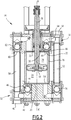
Figure 2 est une vue d'un détail marqué II de laFigure 1 , - la
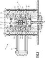
Figure 3 est une vue d'un détail marqué III de laFigure 1 , et - la
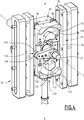
Figure 4 est une vue en perspective d'un système de conversion de la pompe de laFigure 1 . - La pompe 10 représentée sur la
Figure 1 comprend, de manière classique, un bâti 12 et une unité de pompage 14. - En référence à la
Figure 2 , l'unité de pompage 14 comporte, de manière classique, une chambre cylindrique 16 pour la réception du produit fluide à pomper, et un piston 18. - La chambre 16 est solidaire du bâti 12 et est orientée suivant un axe A-A'. Elle est fermée à une première extrémité axiale par une première paroi 20, et à l'extrémité axiale opposée par une deuxième paroi 22.
- Le piston 18 est monté mobile en translation à l'intérieur de la chambre 16 suivant ledit axe A-A'. Il réalise une séparation étanche entre une première partie 24 de la chambre 16, qui s'étend depuis la première paroi 20 jusqu'au piston 18, et une deuxième partie 26 de la chambre 16 qui s'étend depuis la deuxième paroi 22 jusqu'au piston 18. Selon la position du piston 18 à l'intérieur de la chambre 16, le volume de chacune des première et deuxième parties 24, 26 varie.
- Le piston 18 est solidaire d'un arbre 28 orienté parallèlement à l'axe A-A' et de préférence, comme représenté, sensiblement coaxial à l'axe A-A'. Cet arbre 28 s'étend à travers la deuxième paroi 22, dans laquelle un orifice traversant 30 est ménagé à cet effet.
- L'unité de pompage 14 comprend également une alimentation en produit fluide 32 pour alimenter la chambre 16 en produit fluide, et une évacuation de produit fluide 34 pour permettre d'évacuer le produit fluide hors de la chambre 16.
- L'alimentation 32 comprend une entrée d'alimentation 40 pour le raccordement d'une conduite d'alimentation en produit fluide (non représentée), une première branche d'alimentation 42 raccordant fluidiquement ladite entrée 40 à un premier orifice d'alimentation 44 ménagé dans la première paroi 20, et un premier clapet anti-retour d'alimentation 46 monté dans la première branche 42 de sorte à permettre la circulation de fluide depuis l'entrée 40 vers l'orifice 44 en interdisant le refoulement de fluide depuis l'orifice 44 vers l'entrée 40.
- L'évacuation 34 comprend une sortie d'évacuation 50 pour le raccordement d'une conduite d'évacuation du produit fluide (non représentée), une première branche d'évacuation 52 raccordant fluidiquement ladite sortie 50 à un premier orifice d'évacuation 54 ménagé dans la première paroi 20, et un premier clapet anti-retour d'évacuation 56 monté dans la première branche 52 de sorte à permettre la circulation de fluide depuis l'orifice 54 vers la sortie 50 en interdisant le refoulement de fluide depuis la sortie 50 vers l'orifice 54.
- Ainsi, l'unité de pompage 14 est adaptée pour que le déplacement du piston 18 depuis la première paroi 20 vers la deuxième paroi 22 entraîne l'aspiration du produit fluide depuis l'entrée 40 dans la première partie 24 de la chambre 16, et que le déplacement du piston 18 depuis la deuxième paroi 22 vers la première paroi 20 entraîne le refoulement du produit fluide hors de la première partie de la chambre 16, vers la sortie 50.
- Dans l'exemple représenté, la pompe 10 est une pompe à double effet, c'est-à-dire que l'unité de pompage 14 est adaptée pour que le déplacement du piston 18 depuis la deuxième paroi 22 vers la première paroi 20 entraîne également l'aspiration du produit fluide depuis l'entrée 40 dans la deuxième partie 26 de la chambre 16, et que le déplacement du piston 18 depuis la première paroi 20 vers la deuxième paroi 22 entraîne également le refoulement du produit fluide hors de la deuxième partie 26 de la chambre 16, vers la sortie 50.
- A cet effet, l'alimentation 32 comprend également une deuxième branche d'alimentation 58 raccordant fluidiquement l'entrée 40 à un deuxième orifice d'alimentation 60 ménagé dans la deuxième paroi 22, et un deuxième clapet anti-retour d'alimentation 62 monté dans la deuxième branche 58 de sorte à permettre la circulation de fluide depuis l'entrée 40 vers l'orifice 60 en interdisant le refoulement de fluide depuis l'orifice 60 vers l'entrée 40. En outre, l'évacuation 34 comprend également une deuxième branche d'évacuation 64 raccordant fluidiquement la sortie 50 à un deuxième orifice d'évacuation 66 ménagé dans la deuxième paroi 22, et un deuxième clapet anti-retour d'évacuation 68 monté dans la deuxième branche 64 de sorte à permettre la circulation de fluide depuis l'orifice 66 vers la sortie 50 en interdisant le refoulement de fluide depuis la sortie 50 vers l'orifice 66.
- Ainsi, l'unité de pompage 14 est ici constituée par une pompe quatre billes. En variante (non représentée), l'unité de pompage 14 est constituée par une pompe deux billes.
- De retour à la
Figure 1 , la pompe 10 comprend également un système 70 d'entraînement du piston 18 pour déplacer le piston 18 à l'intérieur de la chambre 16 en translation selon un mouvement de va-et-vient suivant l'axe A-A'. - En référence à la
Figure 3 , ce système d'entraînement 70 comprend un arbre d'entrée 72, un moteur 74 pour entraîner ledit arbre d'entrée 72 en rotation autour de son axe relativement au bâti 12, et un système de conversion 76 pour convertir la rotation de l'arbre d'entrée 72 autour de son axe en mouvement de translation du piston 18 suivant l'axe A-A'. - L'arbre d'entrée 72 est allongé suivant un axe B-B' orthogonal à l'axe A-A'. Il est également monté mobile en rotation relativement au bâti 12 autour de ce même axe B-B'.
- L'arbre d'entrée 72 est ainsi adapté pour occuper différentes positions angulaires par rapport au bâti 12, chaque position angulaire étant définie par un angle compris entre 0° et 360° relativement à une position de référence de l'arbre 72, une rotation complète de l'arbre 72 autour de l'axe B-B' ramenant l'arbre 72 à sa position angulaire initiale.
- Le moteur 74 comprend un stator (non représenté) solidaire du bâti 12, et un rotor (non représenté) monté mobile en rotation autour de son axe relativement au bâti 12. Ledit rotor est lié cinématiquement à l'arbre d'entrée 72, typiquement par l'intermédiaire d'un réducteur (non représenté), de sorte que la rotation du rotor entraîne la rotation de l'arbre d'entrée 72 ; en variante, le rotor constitue l'arbre d'entrée 72.
- Le moteur 74 est typiquement constitué par un moteur électrique, par exemple un moteur sans balais ou un moteur asynchrone.
- Le système de conversion 76 comprend un chariot 80 monté mobile en translation relativement au bâti 12 suivant une direction parallèle à l'axe A-A'. Ce chariot 80 est solidaire du piston 18, par l'intermédiaire de l'arbre 28.
- Dans l'exemple représenté, le chariot 80 a une forme générale parallélépipédique.
- Le système de conversion 76 comprend également un système de guidage 82 pour guider le déplacement du chariot 80 relativement au bâti 12.
- Ce système de guidage 82 comprend ici une paire de rails 84 encadrant ensemble le chariot 80 suivant une direction orthogonale aux axes A-A' et B-B', chaque rail 84 étant parallèle à l'axe A-A'. Le système 82 comprend également, pour chaque rail 84, deux galets rotatifs 86 montés sur le chariot 80 et faisant l'interface entre le chariot 80 et le rail 84, chaque galet 86 étant centré sur un axe propre parallèle à l'axe B-B' et étant librement rotatif autour de cet axe relativement au chariot 80.
- Dans l'exemple représenté, chaque galet 86 est positionné au niveau d'une arête respective du chariot 80.
- Le système de conversion 76 comprend également un dispositif de conversion 90 pour convertir la rotation de l'arbre d'entrée 72 autour de son axe B-B' en mouvement de va-et-vient du chariot 80 et, par cet intermédiaire, du piston 18, suivant l'axe A-A'.
- Selon l'invention, ce dispositif de conversion 90 consiste en un système de va-et-vient à pignon et crémaillère.
- Ce système de va-et-vient 90 comprend un demi-pignon 92, une première crémaillère 94 apte à engrener le demi-pignon 92 dans un premier sens, et une deuxième crémaillère 96 apte à engrener le demi-pignon 92 dans un deuxième sens opposé au premier sens. Par « apte à engrener le demi-pignon dans un deuxième sens opposé au premier sens », on comprend ici et dans la suite que, pour un sens de rotation constant du demi-pignon 92, l'engrènement du demi-pignon 92 sur la deuxième crémaillère 96 entraîne un déplacement du demi-pignon 92 relativement à la deuxième crémaillère 96 dans un sens opposé au sens de déplacement du demi-pignon 92 relativement à la première crémaillère 94 lorsqu'il est engrené sur cette dernière.
- Le demi-pignon 92 est monté mobile en rotation relativement au bâti 12 autour de l'axe B-B' et est immobile en translation relativement au bâti 12 suivant l'axe A-A'. Il est cinématiquement lié à l'arbre d'entrée 72 de sorte que la rotation de l'arbre d'entrée 72 entraîne la rotation du demi-pignon 92. En particulier, le demi-pignon 92 est solidaire de l'arbre d'entrée 72.
- Le demi-pignon 92 comprend un secteur angulaire denté 98, le reste du demi-pignon 92 étant dépourvu de dents. En d'autres termes, les dents du demi-pignon 92 sont toutes regroupées dans le secteur angulaire denté 98.
- Le secteur angulaire denté 98 est continu et les dents sont régulièrement réparties dans ce secteur angulaire 98.
- Le secteur angulaire 98 a une étendue angulaire inférieure à 170° et de préférence comprise entre 90° et 130°.
- Le demi-pignon 92 comprend un nombre N de dents, ce nombre N étant ici égal à cinq, sans que cela ne soit limitatif.
- Le demi-pignon 92 est interposé entre les crémaillères 94, 96.
- Chacune des première et deuxième crémaillères 94, 96 est formée dans le chariot 80 et est, de ce fait, solidaire du piston 18 et de l'autre crémaillère 94, 96.
- Chaque crémaillère 94, 96 est rectiligne et est orientée sensiblement parallèlement à l'axe A-A'.
- Chaque crémaillère 94, 96 comprend, de manière connue, un corps 100 et des dents 102 faisant saillie depuis ce corps.
- Ces dents 102 sont, de manière préférentielle, au nombre de N+1, c'est-à-dire que chaque crémaillère 94, 96 comprend une dent de plus que le demi-pignon 92, les crémaillères 94, 96 ayant le même nombre de dents. Ainsi, dans l'exemple représenté, chaque crémaillère 94, 96 comprend six dents 102.
- Avantageusement, toutes les dents 102 ont la même hauteur, c'est-à-dire que la distance séparant le corps 100 du sommet d'une dent 102 est égale à la distance séparant le corps 100 du sommet de chaque autre dent 102. Ainsi, il est possible d'utiliser pour les crémaillères 94, 96 des crémaillères standard, et la gestion des stocks de crémaillères nécessaires à la production de la pompe 10 est facilitée
- Les crémaillères 94, 96 sont espacées l'une de l'autre suivant une direction orthogonale aux axes A-A' et B-B'.
- Les crémaillères 94, 96 se font face, c'est-à-dire que les dents 102 de chaque crémaillère 94, 96 font saillie depuis le corps 100 de la crémaillère 94, 96 en direction de l'autre crémaillère 94, 96. De plus, chaque dent 102 de chaque crémaillère 94, 96 est sensiblement alignée suivant ladite direction orthogonale aux axes A-A' et B-B' avec une dent 102 correspondante de l'autre crémaillère 94, 96.
- Du fait de l'étendue angulaire relativement restreinte du secteur denté 98 du demi-pignon 92 et de la configuration des crémaillères 94, 96, le demi-pignon 92 est configuré pour, au cours de sa rotation, s'engrener alternativement sur la première crémaillère 94 et sur la deuxième crémaillère 96, entraînant ainsi le déplacement du chariot 80, et donc du piston 18, suivant l'axe A-A' alternativement selon un premier sens et selon un deuxième sens. Il est en outre configuré pour, lors des phases de transition entre les première et deuxième crémaillères 94, 96, se désengrener intégralement de la crémaillère 94, 96 qu'il quitte avant de s'engrener sur l'autre crémaillère 94, 96. Ainsi, le système de va-et-vient 90 présente les différentes configurations suivantes :
- une première configuration embrayée, dans laquelle le demi-pignon 92 est engrené sur la première crémaillère 94 ; cette configuration est rencontrée lorsque l'arbre d'entrée 72 occupe une position angulaire comprise dans un premier secteur ;
- une première configuration débrayée, dans laquelle le demi-pignon 92 n'est engrené sur aucune des crémaillères 94, 96, ses dents étant orientées à l'opposé du piston 18; cette configuration est rencontrée lorsque l'arbre d'entrée 72 occupe une position angulaire comprise dans un deuxième secteur juxtaposé au premier secteur ;
- une deuxième configuration embrayée, dans laquelle le demi-pignon 92 est engrené sur la deuxième crémaillère 96, comme montré sur les Figures ; cette configuration est rencontrée lorsque l'arbre d'entrée 72 occupe une position angulaire comprise dans un troisième secteur juxtaposé au deuxième secteur et disjoint du premier secteur ; et
- une deuxième configuration débrayée, dans laquelle le demi-pignon 92 n'est engrené sur aucune des crémaillères 94, 96, ses dents étant orientées vers le piston 18; cette configuration est rencontrée lorsque l'arbre d'entrée 72 occupe une position angulaire comprise dans un quatrième secteur interposé entre les premier et troisième secteurs et disjoint du deuxième secteur.
- Afin d'empêcher tout déplacement du piston 18 dans ces configurations débrayées, le système de conversion 76 comprend également un mécanisme 110, représenté sur la
Figure 4 , d'immobilisation du piston 18 lorsque le système de va-et-vient 90 est en configuration débrayée. - En référence à la
Figure 4 , ce mécanisme d'immobilisation 110 comprend quatre surfaces de butée 112, 114, 116, 118 portées par le chariot 80, et un excentrique 120, c'est-à-dire une pièce excentrée par rapport à son axe de rotation, cinématiquement lié à l'arbre d'entrée 72 de sorte que la rotation de l'arbre d'entrée 72 entraîne la rotation dudit excentrique 120 autour d'un axe d'excentrique constitué ici par l'axe B-B'. - Les surfaces de butée 112, 114, 116, 118 comprennent une première surface de butée 112 et une deuxième surface de butée 114 se faisant face en étant espacées l'une de l'autre suivant l'axe A-A'.
- Chaque surface de butée 112, 114 est au moins en partie orthogonale à l'axe A-A'. Dans l'exemple représentée, chaque surface de butée 112, 114 a une forme globale de tronc de cylindre dont un plan tangent est constitué par un plan orthogonal à l'axe A-A'. En particulier, ce tronc de cylindre a pour axe un axe parallèle à l'axe B-B' et est tronqué par un plan orthogonal à l'axe A-A'.
- Les surfaces de butée 112, 114, 116, 118 comprennent également une troisième surface de butée 116 et une quatrième surface de butée 118 orientées dans des directions opposées l'une à l'autre.
- Chaque surface de butée 116, 118 est au moins en partie orthogonale à l'axe A-A'. Dans l'exemple représentée, chaque surface de butée 116, 118 a une forme globale de tronc de cylindre dont un plan tangent est constitué par un plan orthogonal à l'axe A-A'. En particulier, ce tronc de cylindre a pour axe un axe parallèle à l'axe B-B' et est tronqué par un plan orthogonal à l'axe A-A'.
- Les première et quatrième butées 112, 118 sont chacune orientées à l'opposé du piston 18. Les deuxième et troisième butées 114, 116 chacune orientées vers le piston 18.
- Suivant l'axe A-A', on rencontre successivement, en partant du piston 18 et en s'en éloignant: la première butée 112, la troisième butée 116, l'axe d'excentrique, la quatrième butée 118 et la deuxième butée 114. Ainsi, la première butée 112 et la troisième butée 116 sont chacune interposées entre l'axe d'excentrique et le piston 18, et la deuxième butée 114 et la quatrième butée 118 sont disposées à l'opposé du piston 18 relativement à l'axe d'excentrique.
- L'excentrique 120 est adapté pour être en appui contre les première et troisième surface de butée 112, 116 lorsque le système de va-et-vient 90 est dans sa première configuration débrayée, et pour être en appui contre les deuxième et quatrième surfaces de butée 114, 118 lorsque le système de va-et-vient 90 est dans sa deuxième configuration débrayée.
- A cet effet, l'excentrique 120 comprend un bras 122 cinématiquement lié à l'arbre d'entrée 72 de sorte que la rotation de l'arbre d'entrée 72 entraîne la rotation dudit bras 122 autour de l'axe d'excentrique, et un organe d'appui 124 monté sur ledit bras 122, ledit organe d'appui 124 présentant une surface d'appui primaire 126, orientée à l'opposé de l'axe d'excentrique et apte à reposer contre les première et deuxième surfaces de butée 112, 114, et une surface d'appui secondaire 128, orientée vers l'axe d'excentrique et apte à reposer contre les troisième et quatrième surfaces de butée 116, 118.
- Le bras 122 est en particulier solidaire de l'arbre d'entrée 72.
- L'organe d'appui 124 est ici constitué par un galet monté sur le bras 122 de sorte à être, relativement au bras 122, librement rotatif autour d'un axe parallèle à l'axe d'excentrique.
- Cette pompe 10 est ainsi particulièrement adaptée à une utilisation pour pomper une peinture ou un produit visqueux, du fait du système simple et particulièrement robuste de conversion du mouvement de rotation du moteur 74 en mouvement de va-et-vient du piston 18.
- En outre, cette pompe 10 est particulièrement stable grâce au mécanisme d'immobilisation 110 qui évite que la pompe 10 ne ravale le produit refoulé sous l'effet de la différence de pression existant entre les circuits amont et aval.
- Bien que, dans le mode de réalisation décrit ci-dessus, le système de va-et-vient 90 ne comprenne qu'un seul demi-pignon 92, l'invention ne se limite toutefois pas à ce seul cas. Ainsi, en variante (non représentée), le système de va-et-vient 90 comprend deux demi-pignons. Dans cette variante, les deux demi-pignons sont liés cinématiquement l'un à l'autre de sorte à tourner dans un même sens, et ils encadrent ensemble les première et deuxième crémaillères 94, 96, lesquelles ne sont alors pas positionnées face à face mais dos à dos.
- D'autres variantes de la pompe 10 et en particulier du système de va-et-vient 90 sont encore possibles sans sortir du cadre de l'invention.
Claims (14)
- Pompe (10) pour produit fluide, la pompe (10) comprenant un bâti (12), un piston (18) et un système (70) d'entraînement du piston (18) pour déplacer le piston (18) relativement au bâti (12) en translation selon un mouvement de va-et-vient suivant un axe de déplacement (A-A'), le système d'entraînement (70) comprenant un arbre d'entrée (72) s'étendant suivant un axe de rotation (B-B'), un moteur (74) adapté pour entraîner ledit arbre d'entrée (72) en rotation autour de l'axe de rotation (B-B') relativement au bâti (12), et un système de conversion (76) pour convertir la rotation de l'arbre d'entrée (72) autour de l'axe de rotation (B-B') en un mouvement de translation du piston (18), caractérisée en ce que le système de conversion (76) comprend un système de va-et-vient à pignon et crémaillère (90).
- Pompe (10) selon la revendication 1, dans laquelle le système de va-et-vient à pignon et crémaillère (90) comprend au moins un demi-pignon (92) cinématiquement lié à l'arbre d'entrée (72) de sorte que la rotation de l'arbre d'entrée (72) entraîne la rotation du ou de chaque demi-pignon (92), une première crémaillère (94) solidaire du piston (18) et qui est apte à engrener le demi-pignon (92) ou un premier des demi-pignons, dans un premier sens, et une deuxième crémaillère (96) solidaire du piston (18) et qui est apte à engrener le demi-pignon (92) ou un deuxième des demi-pignons, dans un deuxième sens opposé au premier sens.
- Pompe (10) selon la revendication 2, dans laquelle le système de va-et-vient à pignon et crémaillère (90) comprend un unique demi-pignon (92), ledit demi-pignon (92) étant interposé entre les première et deuxième crémaillères (94, 96), lesdites première et deuxième crémaillères (94, 96) se faisant face.
- Pompe (10) selon la revendication 3, dans laquelle chaque crémaillère (94, 96) comprend au moins une dent (102) de plus que le demi-pignon (92), les crémaillères (94, 96) ayant le même nombre de dents (102).
- Pompe (10) selon l'une quelconque des revendications 2 à 4, dans laquelle chaque crémaillère (94, 96) comprend une pluralité de dents (102), lesdites dents (102) ayant toutes une même hauteur.
- Pompe (10) selon l'une quelconque des revendications 2 à 5, dans laquelle chaque crémaillère (94, 96) est rectiligne et est orientée sensiblement parallèlement à l'axe de déplacement (A-A').
- Pompe (10) selon l'une quelconque des revendications 2 à 6, dans laquelle le système de conversion (76) comprend un chariot (80) monté mobile en translation relativement au bâti (12), le piston (18) étant solidaire dudit chariot (80) et les crémaillères (94, 96) faisant partie dudit chariot (80).
- Pompe (10) selon la revendication 7, dans laquelle le système de conversion (76) comprend un système de guidage (82) pour guider le déplacement du chariot (80) relativement au bâti (12), ledit système de guidage (82) comprenant au moins une paire de rails (84) encadrant ensemble le chariot (80) suivant une direction orthogonale à l'axe de déplacement (A-A'), chaque rail (84) étant parallèle à l'axe de déplacement (A-A'), et, pour chaque rail (84), au moins deux galets rotatifs (86) montés sur le chariot (80) et faisant l'interface entre le chariot (80) et le rail (84).
- Pompe (10) selon la revendication 7 ou 8, dans laquelle le système de va-et-vient à pignon et crémaillère (90) présente au moins une configuration débrayée dans laquelle aucun demi-pignon (92) n'est engrené ni sur la première crémaillère (94) ni sur la deuxième crémaillère (96), et le système de conversion (76) comprend un mécanisme (110) d'immobilisation du piston (18) lorsque le système de va-et-vient à pignon et crémaillère (90) est en configuration débrayée, ledit mécanisme d'immobilisation (110) comprenant :- au moins une surface de butée (112, 114, 116, 118) portée par le chariot (80), et- un excentrique (120) cinématiquement lié à l'arbre d'entrée (72) de sorte que la rotation de l'arbre d'entrée (72) entraîne la rotation dudit excentrique (120) autour d'un axe d'excentrique, l'excentrique (120) étant adapté pour être en appui contre la surface de butée (112, 114, 116, 118) ou contre au moins une des surfaces de butée (112, 114, 116, 118) lorsque le système de va-et-vient à pignon et crémaillère (90) est en configuration débrayée.
- Pompe (10) selon la revendication 9, dans laquelle les surfaces de butée (112, 114, 116, 118) comprennent une première surface de butée (112) et une deuxième surface de butée (114) espacées l'une de l'autre suivant l'axe de déplacement (A-A'), l'excentrique (120) étant interposée entre lesdites première et deuxième surfaces de butée (112, 114).
- Pompe (10) selon la revendication 9 ou 10, dans laquelle l'excentrique (120) comprend un bras (122) cinématiquement lié à l'arbre d'entrée (72) de sorte que la rotation de l'arbre d'entrée (72) entraîne la rotation dudit bras (122) autour de l'axe d'excentrique, et un galet (124) monté sur ledit bras (122) de sorte à être, relativement au bras (122), librement rotatif autour d'un axe parallèle à l'axe d'excentrique, ledit galet (124) définissant au moins une surface d'appui (126, 128) de l'excentrique (120) contre la ou chaque surface de butée (112, 114, 116, 118).
- Pompe (10) selon l'une quelconque des revendications précédentes, ladite pompe (10) étant une pompe à double effet.
- Pompe (10) selon l'une quelconque des revendications précédentes, dans laquelle le moteur (74) est un moteur électrique.
- Utilisation d'une pompe (10) selon l'une quelconque des revendications précédentes pour pomper une peinture, un vernis, ou un produit visqueux.
Applications Claiming Priority (1)
| Application Number | Priority Date | Filing Date | Title |
|---|---|---|---|
| FR1858152A FR3085729B1 (fr) | 2018-09-12 | 2018-09-12 | Pompe avec systeme de va-et-vient a pignon et cremaillere et utilisation d'une telle pompe |
Publications (2)
| Publication Number | Publication Date |
|---|---|
| EP3623618A1 true EP3623618A1 (fr) | 2020-03-18 |
| EP3623618B1 EP3623618B1 (fr) | 2022-05-18 |
Family
ID=65201375
Family Applications (1)
| Application Number | Title | Priority Date | Filing Date |
|---|---|---|---|
| EP19196776.9A Active EP3623618B1 (fr) | 2018-09-12 | 2019-09-11 | Pompe avec système de va-et-vient à pignon et crémaillère et utilisation d'une telle pompe |
Country Status (3)
| Country | Link |
|---|---|
| EP (1) | EP3623618B1 (fr) |
| ES (1) | ES2918384T3 (fr) |
| FR (1) | FR3085729B1 (fr) |
Cited By (2)
| Publication number | Priority date | Publication date | Assignee | Title |
|---|---|---|---|---|
| CN112196759A (zh) * | 2020-04-15 | 2021-01-08 | 深圳市飞猫电器有限公司 | 脉冲水泵以及洗牙器 |
| CN117212095A (zh) * | 2023-10-09 | 2023-12-12 | 北京航威硕杰电子有限责任公司 | 一种双向增压齿条动力泵 |
Families Citing this family (2)
| Publication number | Priority date | Publication date | Assignee | Title |
|---|---|---|---|---|
| US10907622B2 (en) * | 2018-05-02 | 2021-02-02 | Sherman Production Solutions, Llc | Reciprocating injection pump and method of use |
| CN112123071A (zh) * | 2020-10-28 | 2020-12-25 | 常州钟楼银星汽车附件有限公司 | 一种双工位工件打磨装置 |
Citations (5)
| Publication number | Priority date | Publication date | Assignee | Title |
|---|---|---|---|---|
| FR2608711A1 (fr) * | 1986-12-17 | 1988-06-24 | Goulet Michel | Dispositif de transformation d'un mouvement lineaire alternatif en un mouvement de rotation |
| KR100781391B1 (ko) * | 2002-07-24 | 2007-11-30 | 인제대학교 산학협력단 | 구동모터를 이용한 왕복펌프 |
| US20140219819A1 (en) | 2011-09-09 | 2014-08-07 | Graco Minnesota Inc. | Reciprocating positive displacement pump with electric reversing motor |
| CN106762500A (zh) * | 2016-12-30 | 2017-05-31 | 北京工业大学 | 一种齿轮齿条传动的卧式三缸柱塞往复泵 |
| CN107795449A (zh) * | 2017-11-28 | 2018-03-13 | 西南石油大学 | 一种凸轮限位的齿扇齿条式往复泵 |
-
2018
- 2018-09-12 FR FR1858152A patent/FR3085729B1/fr not_active Expired - Fee Related
-
2019
- 2019-09-11 ES ES19196776T patent/ES2918384T3/es active Active
- 2019-09-11 EP EP19196776.9A patent/EP3623618B1/fr active Active
Patent Citations (5)
| Publication number | Priority date | Publication date | Assignee | Title |
|---|---|---|---|---|
| FR2608711A1 (fr) * | 1986-12-17 | 1988-06-24 | Goulet Michel | Dispositif de transformation d'un mouvement lineaire alternatif en un mouvement de rotation |
| KR100781391B1 (ko) * | 2002-07-24 | 2007-11-30 | 인제대학교 산학협력단 | 구동모터를 이용한 왕복펌프 |
| US20140219819A1 (en) | 2011-09-09 | 2014-08-07 | Graco Minnesota Inc. | Reciprocating positive displacement pump with electric reversing motor |
| CN106762500A (zh) * | 2016-12-30 | 2017-05-31 | 北京工业大学 | 一种齿轮齿条传动的卧式三缸柱塞往复泵 |
| CN107795449A (zh) * | 2017-11-28 | 2018-03-13 | 西南石油大学 | 一种凸轮限位的齿扇齿条式往复泵 |
Cited By (3)
| Publication number | Priority date | Publication date | Assignee | Title |
|---|---|---|---|---|
| CN112196759A (zh) * | 2020-04-15 | 2021-01-08 | 深圳市飞猫电器有限公司 | 脉冲水泵以及洗牙器 |
| CN117212095A (zh) * | 2023-10-09 | 2023-12-12 | 北京航威硕杰电子有限责任公司 | 一种双向增压齿条动力泵 |
| CN117212095B (zh) * | 2023-10-09 | 2024-02-13 | 北京航威硕杰电子有限责任公司 | 一种双向增压齿条动力泵 |
Also Published As
| Publication number | Publication date |
|---|---|
| FR3085729A1 (fr) | 2020-03-13 |
| ES2918384T3 (es) | 2022-07-15 |
| FR3085729B1 (fr) | 2021-11-19 |
| EP3623618B1 (fr) | 2022-05-18 |
Similar Documents
| Publication | Publication Date | Title |
|---|---|---|
| EP3623618B1 (fr) | Pompe avec système de va-et-vient à pignon et crémaillère et utilisation d'une telle pompe | |
| EP3025058B1 (fr) | Sous-ensemble oscillo-rotatif et dispositif de pompage volumétrique oscillo-rotatif pour pompage volumétrique d'un fluide | |
| CA2918927C (fr) | Sous-ensemble oscillo-rotatif pour pompage d'un fluide et dispositif de pompage oscillo-rotatif | |
| EP2501964B1 (fr) | Vanne a obturateur rotatif et installation de traitement d'eau comportant une telle vanne | |
| EP2771572A2 (fr) | Échangeur de pression volumétrique pour une installation de dessalement d'eau de mer et installation de dessalement | |
| FR2908844A1 (fr) | Pompe a palettes a deplacement variable | |
| FR3011290A3 (fr) | Pompe a engrenages a deplacement positif | |
| BE1030413B1 (fr) | Pompe de fluide pour turbomachine d'aéronef, circuit de lubrification et turbomachine d'aéronef | |
| WO2017109329A1 (fr) | Système de refroidissement et lubrification pour dispositif d'étanchéité pour piston | |
| WO2021156574A1 (fr) | Dispositif de distribution de liquide oscillo-rotatif avec ressort et sa méthode | |
| EP0400496B1 (fr) | Pompe volumétrique et procédé pour pomper volumétriquement | |
| WO2012084033A1 (fr) | Ensemble de micro pompe | |
| EP3992425A1 (fr) | Pompe modulaire | |
| EP2422087B1 (fr) | Pompe volumetrique comprenant un absorbeur de pression | |
| EP3677775B1 (fr) | Microcentrale hydraulique | |
| EP4409139B1 (fr) | Pompe volumetrique a lobes | |
| EP3228866B1 (fr) | Pompe à fuel à engrenages | |
| EP3772588A1 (fr) | Bloc modulaire pour pompe électrique à encombrement limité et pompe associée | |
| WO2000050773A2 (fr) | Pompe volumetrique double | |
| WO2025114111A1 (fr) | Pompe volumétrique à pression régulée | |
| EP3824183A1 (fr) | Pompe de précision alternative a débit continu | |
| FR3003313A1 (fr) | Pompe volumetrique a soufflets | |
| CH702249B1 (fr) | Vanne à obturateur rotatif et installation de traitement d'eau comportant une telle vanne. | |
| FR3087231A1 (fr) | Pompe a rotors contrarotatifs | |
| FR2587765A1 (fr) | Transformateur de forte puissance hydraulique a debit regulier |
Legal Events
| Date | Code | Title | Description |
|---|---|---|---|
| PUAI | Public reference made under article 153(3) epc to a published international application that has entered the european phase |
Free format text: ORIGINAL CODE: 0009012 |
|
| STAA | Information on the status of an ep patent application or granted ep patent |
Free format text: STATUS: THE APPLICATION HAS BEEN PUBLISHED |
|
| AK | Designated contracting states |
Kind code of ref document: A1 Designated state(s): AL AT BE BG CH CY CZ DE DK EE ES FI FR GB GR HR HU IE IS IT LI LT LU LV MC MK MT NL NO PL PT RO RS SE SI SK SM TR |
|
| AX | Request for extension of the european patent |
Extension state: BA ME |
|
| STAA | Information on the status of an ep patent application or granted ep patent |
Free format text: STATUS: REQUEST FOR EXAMINATION WAS MADE |
|
| STAA | Information on the status of an ep patent application or granted ep patent |
Free format text: STATUS: EXAMINATION IS IN PROGRESS |
|
| 17P | Request for examination filed |
Effective date: 20200828 |
|
| RBV | Designated contracting states (corrected) |
Designated state(s): AL AT BE BG CH CY CZ DE DK EE ES FI FR GB GR HR HU IE IS IT LI LT LU LV MC MK MT NL NO PL PT RO RS SE SI SK SM TR |
|
| 17Q | First examination report despatched |
Effective date: 20201001 |
|
| GRAP | Despatch of communication of intention to grant a patent |
Free format text: ORIGINAL CODE: EPIDOSNIGR1 |
|
| STAA | Information on the status of an ep patent application or granted ep patent |
Free format text: STATUS: GRANT OF PATENT IS INTENDED |
|
| INTG | Intention to grant announced |
Effective date: 20210407 |
|
| GRAJ | Information related to disapproval of communication of intention to grant by the applicant or resumption of examination proceedings by the epo deleted |
Free format text: ORIGINAL CODE: EPIDOSDIGR1 |
|
| STAA | Information on the status of an ep patent application or granted ep patent |
Free format text: STATUS: EXAMINATION IS IN PROGRESS |
|
| INTC | Intention to grant announced (deleted) | ||
| GRAP | Despatch of communication of intention to grant a patent |
Free format text: ORIGINAL CODE: EPIDOSNIGR1 |
|
| STAA | Information on the status of an ep patent application or granted ep patent |
Free format text: STATUS: GRANT OF PATENT IS INTENDED |
|
| INTG | Intention to grant announced |
Effective date: 20211222 |
|
| GRAS | Grant fee paid |
Free format text: ORIGINAL CODE: EPIDOSNIGR3 |
|
| GRAA | (expected) grant |
Free format text: ORIGINAL CODE: 0009210 |
|
| STAA | Information on the status of an ep patent application or granted ep patent |
Free format text: STATUS: THE PATENT HAS BEEN GRANTED |
|
| AK | Designated contracting states |
Kind code of ref document: B1 Designated state(s): AL AT BE BG CH CY CZ DE DK EE ES FI FR GB GR HR HU IE IS IT LI LT LU LV MC MK MT NL NO PL PT RO RS SE SI SK SM TR |
|
| REG | Reference to a national code |
Ref country code: GB Ref legal event code: FG4D Free format text: NOT ENGLISH |
|
| REG | Reference to a national code |
Ref country code: CH Ref legal event code: EP |
|
| REG | Reference to a national code |
Ref country code: IE Ref legal event code: FG4D Free format text: LANGUAGE OF EP DOCUMENT: FRENCH |
|
| REG | Reference to a national code |
Ref country code: DE Ref legal event code: R096 Ref document number: 602019015040 Country of ref document: DE |
|
| REG | Reference to a national code |
Ref country code: AT Ref legal event code: REF Ref document number: 1493287 Country of ref document: AT Kind code of ref document: T Effective date: 20220615 |
|
| REG | Reference to a national code |
Ref country code: ES Ref legal event code: FG2A Ref document number: 2918384 Country of ref document: ES Kind code of ref document: T3 Effective date: 20220715 |
|
| REG | Reference to a national code |
Ref country code: LT Ref legal event code: MG9D |
|
| REG | Reference to a national code |
Ref country code: NL Ref legal event code: MP Effective date: 20220518 |
|
| REG | Reference to a national code |
Ref country code: AT Ref legal event code: MK05 Ref document number: 1493287 Country of ref document: AT Kind code of ref document: T Effective date: 20220518 |
|
| PG25 | Lapsed in a contracting state [announced via postgrant information from national office to epo] |
Ref country code: SE Free format text: LAPSE BECAUSE OF FAILURE TO SUBMIT A TRANSLATION OF THE DESCRIPTION OR TO PAY THE FEE WITHIN THE PRESCRIBED TIME-LIMIT Effective date: 20220518 Ref country code: PT Free format text: LAPSE BECAUSE OF FAILURE TO SUBMIT A TRANSLATION OF THE DESCRIPTION OR TO PAY THE FEE WITHIN THE PRESCRIBED TIME-LIMIT Effective date: 20220919 Ref country code: NO Free format text: LAPSE BECAUSE OF FAILURE TO SUBMIT A TRANSLATION OF THE DESCRIPTION OR TO PAY THE FEE WITHIN THE PRESCRIBED TIME-LIMIT Effective date: 20220818 Ref country code: NL Free format text: LAPSE BECAUSE OF FAILURE TO SUBMIT A TRANSLATION OF THE DESCRIPTION OR TO PAY THE FEE WITHIN THE PRESCRIBED TIME-LIMIT Effective date: 20220518 Ref country code: LT Free format text: LAPSE BECAUSE OF FAILURE TO SUBMIT A TRANSLATION OF THE DESCRIPTION OR TO PAY THE FEE WITHIN THE PRESCRIBED TIME-LIMIT Effective date: 20220518 Ref country code: HR Free format text: LAPSE BECAUSE OF FAILURE TO SUBMIT A TRANSLATION OF THE DESCRIPTION OR TO PAY THE FEE WITHIN THE PRESCRIBED TIME-LIMIT Effective date: 20220518 Ref country code: GR Free format text: LAPSE BECAUSE OF FAILURE TO SUBMIT A TRANSLATION OF THE DESCRIPTION OR TO PAY THE FEE WITHIN THE PRESCRIBED TIME-LIMIT Effective date: 20220819 Ref country code: FI Free format text: LAPSE BECAUSE OF FAILURE TO SUBMIT A TRANSLATION OF THE DESCRIPTION OR TO PAY THE FEE WITHIN THE PRESCRIBED TIME-LIMIT Effective date: 20220518 Ref country code: BG Free format text: LAPSE BECAUSE OF FAILURE TO SUBMIT A TRANSLATION OF THE DESCRIPTION OR TO PAY THE FEE WITHIN THE PRESCRIBED TIME-LIMIT Effective date: 20220818 Ref country code: AT Free format text: LAPSE BECAUSE OF FAILURE TO SUBMIT A TRANSLATION OF THE DESCRIPTION OR TO PAY THE FEE WITHIN THE PRESCRIBED TIME-LIMIT Effective date: 20220518 |
|
| PG25 | Lapsed in a contracting state [announced via postgrant information from national office to epo] |
Ref country code: RS Free format text: LAPSE BECAUSE OF FAILURE TO SUBMIT A TRANSLATION OF THE DESCRIPTION OR TO PAY THE FEE WITHIN THE PRESCRIBED TIME-LIMIT Effective date: 20220518 Ref country code: PL Free format text: LAPSE BECAUSE OF FAILURE TO SUBMIT A TRANSLATION OF THE DESCRIPTION OR TO PAY THE FEE WITHIN THE PRESCRIBED TIME-LIMIT Effective date: 20220518 Ref country code: LV Free format text: LAPSE BECAUSE OF FAILURE TO SUBMIT A TRANSLATION OF THE DESCRIPTION OR TO PAY THE FEE WITHIN THE PRESCRIBED TIME-LIMIT Effective date: 20220518 Ref country code: IS Free format text: LAPSE BECAUSE OF FAILURE TO SUBMIT A TRANSLATION OF THE DESCRIPTION OR TO PAY THE FEE WITHIN THE PRESCRIBED TIME-LIMIT Effective date: 20220918 |
|
| PG25 | Lapsed in a contracting state [announced via postgrant information from national office to epo] |
Ref country code: SM Free format text: LAPSE BECAUSE OF FAILURE TO SUBMIT A TRANSLATION OF THE DESCRIPTION OR TO PAY THE FEE WITHIN THE PRESCRIBED TIME-LIMIT Effective date: 20220518 Ref country code: SK Free format text: LAPSE BECAUSE OF FAILURE TO SUBMIT A TRANSLATION OF THE DESCRIPTION OR TO PAY THE FEE WITHIN THE PRESCRIBED TIME-LIMIT Effective date: 20220518 Ref country code: RO Free format text: LAPSE BECAUSE OF FAILURE TO SUBMIT A TRANSLATION OF THE DESCRIPTION OR TO PAY THE FEE WITHIN THE PRESCRIBED TIME-LIMIT Effective date: 20220518 Ref country code: EE Free format text: LAPSE BECAUSE OF FAILURE TO SUBMIT A TRANSLATION OF THE DESCRIPTION OR TO PAY THE FEE WITHIN THE PRESCRIBED TIME-LIMIT Effective date: 20220518 Ref country code: DK Free format text: LAPSE BECAUSE OF FAILURE TO SUBMIT A TRANSLATION OF THE DESCRIPTION OR TO PAY THE FEE WITHIN THE PRESCRIBED TIME-LIMIT Effective date: 20220518 Ref country code: CZ Free format text: LAPSE BECAUSE OF FAILURE TO SUBMIT A TRANSLATION OF THE DESCRIPTION OR TO PAY THE FEE WITHIN THE PRESCRIBED TIME-LIMIT Effective date: 20220518 |
|
| REG | Reference to a national code |
Ref country code: DE Ref legal event code: R097 Ref document number: 602019015040 Country of ref document: DE |
|
| PLBE | No opposition filed within time limit |
Free format text: ORIGINAL CODE: 0009261 |
|
| STAA | Information on the status of an ep patent application or granted ep patent |
Free format text: STATUS: NO OPPOSITION FILED WITHIN TIME LIMIT |
|
| PG25 | Lapsed in a contracting state [announced via postgrant information from national office to epo] |
Ref country code: AL Free format text: LAPSE BECAUSE OF FAILURE TO SUBMIT A TRANSLATION OF THE DESCRIPTION OR TO PAY THE FEE WITHIN THE PRESCRIBED TIME-LIMIT Effective date: 20220518 |
|
| 26N | No opposition filed |
Effective date: 20230221 |
|
| PG25 | Lapsed in a contracting state [announced via postgrant information from national office to epo] |
Ref country code: MC Free format text: LAPSE BECAUSE OF FAILURE TO SUBMIT A TRANSLATION OF THE DESCRIPTION OR TO PAY THE FEE WITHIN THE PRESCRIBED TIME-LIMIT Effective date: 20220518 |
|
| REG | Reference to a national code |
Ref country code: BE Ref legal event code: MM Effective date: 20220930 |
|
| PG25 | Lapsed in a contracting state [announced via postgrant information from national office to epo] |
Ref country code: SI Free format text: LAPSE BECAUSE OF FAILURE TO SUBMIT A TRANSLATION OF THE DESCRIPTION OR TO PAY THE FEE WITHIN THE PRESCRIBED TIME-LIMIT Effective date: 20220518 |
|
| PG25 | Lapsed in a contracting state [announced via postgrant information from national office to epo] |
Ref country code: LU Free format text: LAPSE BECAUSE OF NON-PAYMENT OF DUE FEES Effective date: 20220911 |
|
| PG25 | Lapsed in a contracting state [announced via postgrant information from national office to epo] |
Ref country code: IE Free format text: LAPSE BECAUSE OF NON-PAYMENT OF DUE FEES Effective date: 20220911 |
|
| PG25 | Lapsed in a contracting state [announced via postgrant information from national office to epo] |
Ref country code: BE Free format text: LAPSE BECAUSE OF NON-PAYMENT OF DUE FEES Effective date: 20220930 |
|
| PG25 | Lapsed in a contracting state [announced via postgrant information from national office to epo] |
Ref country code: HU Free format text: LAPSE BECAUSE OF FAILURE TO SUBMIT A TRANSLATION OF THE DESCRIPTION OR TO PAY THE FEE WITHIN THE PRESCRIBED TIME-LIMIT; INVALID AB INITIO Effective date: 20190911 |
|
| PG25 | Lapsed in a contracting state [announced via postgrant information from national office to epo] |
Ref country code: CY Free format text: LAPSE BECAUSE OF FAILURE TO SUBMIT A TRANSLATION OF THE DESCRIPTION OR TO PAY THE FEE WITHIN THE PRESCRIBED TIME-LIMIT Effective date: 20220511 |
|
| PG25 | Lapsed in a contracting state [announced via postgrant information from national office to epo] |
Ref country code: MK Free format text: LAPSE BECAUSE OF FAILURE TO SUBMIT A TRANSLATION OF THE DESCRIPTION OR TO PAY THE FEE WITHIN THE PRESCRIBED TIME-LIMIT Effective date: 20220511 |
|
| PG25 | Lapsed in a contracting state [announced via postgrant information from national office to epo] |
Ref country code: MT Free format text: LAPSE BECAUSE OF FAILURE TO SUBMIT A TRANSLATION OF THE DESCRIPTION OR TO PAY THE FEE WITHIN THE PRESCRIBED TIME-LIMIT Effective date: 20220511 |
|
| PG25 | Lapsed in a contracting state [announced via postgrant information from national office to epo] |
Ref country code: BG Free format text: LAPSE BECAUSE OF FAILURE TO SUBMIT A TRANSLATION OF THE DESCRIPTION OR TO PAY THE FEE WITHIN THE PRESCRIBED TIME-LIMIT Effective date: 20220518 |
|
| PG25 | Lapsed in a contracting state [announced via postgrant information from national office to epo] |
Ref country code: BG Free format text: LAPSE BECAUSE OF FAILURE TO SUBMIT A TRANSLATION OF THE DESCRIPTION OR TO PAY THE FEE WITHIN THE PRESCRIBED TIME-LIMIT Effective date: 20220518 |
|
| REG | Reference to a national code |
Ref country code: CH Ref legal event code: U11 Free format text: ST27 STATUS EVENT CODE: U-0-0-U10-U11 (AS PROVIDED BY THE NATIONAL OFFICE) Effective date: 20251001 |
|
| PGFP | Annual fee paid to national office [announced via postgrant information from national office to epo] |
Ref country code: DE Payment date: 20250916 Year of fee payment: 7 |
|
| PGFP | Annual fee paid to national office [announced via postgrant information from national office to epo] |
Ref country code: TR Payment date: 20250905 Year of fee payment: 7 Ref country code: IT Payment date: 20250909 Year of fee payment: 7 |
|
| PGFP | Annual fee paid to national office [announced via postgrant information from national office to epo] |
Ref country code: GB Payment date: 20250919 Year of fee payment: 7 |
|
| PGFP | Annual fee paid to national office [announced via postgrant information from national office to epo] |
Ref country code: FR Payment date: 20250929 Year of fee payment: 7 |
|
| REG | Reference to a national code |
Ref country code: CH Ref legal event code: R18 Free format text: ST27 STATUS EVENT CODE: U-0-0-R10-R18 (AS PROVIDED BY THE NATIONAL OFFICE) Effective date: 20260106 |
|
| PGFP | Annual fee paid to national office [announced via postgrant information from national office to epo] |
Ref country code: CH Payment date: 20251001 Year of fee payment: 7 |
|
| PGFP | Annual fee paid to national office [announced via postgrant information from national office to epo] |
Ref country code: ES Payment date: 20251015 Year of fee payment: 7 |