EP3623575A1 - Serpentine turn cover for gas turbine stator vane assembly - Google Patents
Serpentine turn cover for gas turbine stator vane assembly Download PDFInfo
- Publication number
- EP3623575A1 EP3623575A1 EP19184771.4A EP19184771A EP3623575A1 EP 3623575 A1 EP3623575 A1 EP 3623575A1 EP 19184771 A EP19184771 A EP 19184771A EP 3623575 A1 EP3623575 A1 EP 3623575A1
- Authority
- EP
- European Patent Office
- Prior art keywords
- collar
- outer diameter
- diameter platform
- stator vane
- gas turbine
- Prior art date
- Legal status (The legal status is an assumption and is not a legal conclusion. Google has not performed a legal analysis and makes no representation as to the accuracy of the status listed.)
- Granted
Links
- WYTGDNHDOZPMIW-RCBQFDQVSA-N alstonine Natural products C1=CC2=C3C=CC=CC3=NC2=C2N1C[C@H]1[C@H](C)OC=C(C(=O)OC)[C@H]1C2 WYTGDNHDOZPMIW-RCBQFDQVSA-N 0.000 title description 7
- 238000001816 cooling Methods 0.000 claims abstract description 23
- 238000000034 method Methods 0.000 claims description 12
- 239000002184 metal Substances 0.000 claims description 9
- 238000003466 welding Methods 0.000 claims description 5
- 238000005266 casting Methods 0.000 claims description 4
- 239000007789 gas Substances 0.000 description 23
- 230000000712 assembly Effects 0.000 description 7
- 238000000429 assembly Methods 0.000 description 7
- 239000000446 fuel Substances 0.000 description 5
- 239000000567 combustion gas Substances 0.000 description 4
- 238000013461 design Methods 0.000 description 4
- 239000000284 extract Substances 0.000 description 4
- 238000004519 manufacturing process Methods 0.000 description 4
- 230000008569 process Effects 0.000 description 4
- 238000000149 argon plasma sintering Methods 0.000 description 3
- 238000005192 partition Methods 0.000 description 3
- 230000009467 reduction Effects 0.000 description 3
- 230000003068 static effect Effects 0.000 description 3
- 239000000654 additive Substances 0.000 description 2
- 230000000996 additive effect Effects 0.000 description 2
- 239000012809 cooling fluid Substances 0.000 description 2
- 230000000977 initiatory effect Effects 0.000 description 2
- 238000005304 joining Methods 0.000 description 2
- 239000000463 material Substances 0.000 description 2
- 238000003491 array Methods 0.000 description 1
- 230000008901 benefit Effects 0.000 description 1
- 238000005219 brazing Methods 0.000 description 1
- 230000008859 change Effects 0.000 description 1
- 238000004891 communication Methods 0.000 description 1
- 230000006835 compression Effects 0.000 description 1
- 238000007906 compression Methods 0.000 description 1
- 238000012937 correction Methods 0.000 description 1
- 238000009826 distribution Methods 0.000 description 1
- 239000012530 fluid Substances 0.000 description 1
- 238000010348 incorporation Methods 0.000 description 1
- 238000005495 investment casting Methods 0.000 description 1
- 238000005259 measurement Methods 0.000 description 1
- 230000007246 mechanism Effects 0.000 description 1
- 238000012986 modification Methods 0.000 description 1
- 230000004048 modification Effects 0.000 description 1
- 238000005457 optimization Methods 0.000 description 1
- 238000013021 overheating Methods 0.000 description 1
- 239000000843 powder Substances 0.000 description 1
- 230000003252 repetitive effect Effects 0.000 description 1
- 230000004044 response Effects 0.000 description 1
- 238000000926 separation method Methods 0.000 description 1
- 238000005382 thermal cycling Methods 0.000 description 1
- 238000012546 transfer Methods 0.000 description 1
Images


Classifications
-
- F—MECHANICAL ENGINEERING; LIGHTING; HEATING; WEAPONS; BLASTING
- F01—MACHINES OR ENGINES IN GENERAL; ENGINE PLANTS IN GENERAL; STEAM ENGINES
- F01D—NON-POSITIVE DISPLACEMENT MACHINES OR ENGINES, e.g. STEAM TURBINES
- F01D5/00—Blades; Blade-carrying members; Heating, heat-insulating, cooling or antivibration means on the blades or the members
- F01D5/02—Blade-carrying members, e.g. rotors
- F01D5/08—Heating, heat-insulating or cooling means
- F01D5/085—Heating, heat-insulating or cooling means cooling fluid circulating inside the rotor
- F01D5/087—Heating, heat-insulating or cooling means cooling fluid circulating inside the rotor in the radial passages of the rotor disc
-
- F—MECHANICAL ENGINEERING; LIGHTING; HEATING; WEAPONS; BLASTING
- F01—MACHINES OR ENGINES IN GENERAL; ENGINE PLANTS IN GENERAL; STEAM ENGINES
- F01D—NON-POSITIVE DISPLACEMENT MACHINES OR ENGINES, e.g. STEAM TURBINES
- F01D5/00—Blades; Blade-carrying members; Heating, heat-insulating, cooling or antivibration means on the blades or the members
- F01D5/12—Blades
- F01D5/14—Form or construction
- F01D5/147—Construction, i.e. structural features, e.g. of weight-saving hollow blades
-
- F—MECHANICAL ENGINEERING; LIGHTING; HEATING; WEAPONS; BLASTING
- F01—MACHINES OR ENGINES IN GENERAL; ENGINE PLANTS IN GENERAL; STEAM ENGINES
- F01D—NON-POSITIVE DISPLACEMENT MACHINES OR ENGINES, e.g. STEAM TURBINES
- F01D5/00—Blades; Blade-carrying members; Heating, heat-insulating, cooling or antivibration means on the blades or the members
- F01D5/12—Blades
- F01D5/14—Form or construction
- F01D5/18—Hollow blades, i.e. blades with cooling or heating channels or cavities; Heating, heat-insulating or cooling means on blades
- F01D5/186—Film cooling
-
- F—MECHANICAL ENGINEERING; LIGHTING; HEATING; WEAPONS; BLASTING
- F01—MACHINES OR ENGINES IN GENERAL; ENGINE PLANTS IN GENERAL; STEAM ENGINES
- F01D—NON-POSITIVE DISPLACEMENT MACHINES OR ENGINES, e.g. STEAM TURBINES
- F01D5/00—Blades; Blade-carrying members; Heating, heat-insulating, cooling or antivibration means on the blades or the members
- F01D5/12—Blades
- F01D5/14—Form or construction
- F01D5/18—Hollow blades, i.e. blades with cooling or heating channels or cavities; Heating, heat-insulating or cooling means on blades
- F01D5/187—Convection cooling
-
- F—MECHANICAL ENGINEERING; LIGHTING; HEATING; WEAPONS; BLASTING
- F01—MACHINES OR ENGINES IN GENERAL; ENGINE PLANTS IN GENERAL; STEAM ENGINES
- F01D—NON-POSITIVE DISPLACEMENT MACHINES OR ENGINES, e.g. STEAM TURBINES
- F01D9/00—Stators
- F01D9/02—Nozzles; Nozzle boxes; Stator blades; Guide conduits, e.g. individual nozzles
- F01D9/04—Nozzles; Nozzle boxes; Stator blades; Guide conduits, e.g. individual nozzles forming ring or sector
- F01D9/041—Nozzles; Nozzle boxes; Stator blades; Guide conduits, e.g. individual nozzles forming ring or sector using blades
-
- F—MECHANICAL ENGINEERING; LIGHTING; HEATING; WEAPONS; BLASTING
- F01—MACHINES OR ENGINES IN GENERAL; ENGINE PLANTS IN GENERAL; STEAM ENGINES
- F01D—NON-POSITIVE DISPLACEMENT MACHINES OR ENGINES, e.g. STEAM TURBINES
- F01D9/00—Stators
- F01D9/06—Fluid supply conduits to nozzles or the like
- F01D9/065—Fluid supply or removal conduits traversing the working fluid flow, e.g. for lubrication-, cooling-, or sealing fluids
-
- F—MECHANICAL ENGINEERING; LIGHTING; HEATING; WEAPONS; BLASTING
- F05—INDEXING SCHEMES RELATING TO ENGINES OR PUMPS IN VARIOUS SUBCLASSES OF CLASSES F01-F04
- F05D—INDEXING SCHEME FOR ASPECTS RELATING TO NON-POSITIVE-DISPLACEMENT MACHINES OR ENGINES, GAS-TURBINES OR JET-PROPULSION PLANTS
- F05D2230/00—Manufacture
- F05D2230/20—Manufacture essentially without removing material
- F05D2230/23—Manufacture essentially without removing material by permanently joining parts together
- F05D2230/232—Manufacture essentially without removing material by permanently joining parts together by welding
- F05D2230/237—Brazing
-
- F—MECHANICAL ENGINEERING; LIGHTING; HEATING; WEAPONS; BLASTING
- F05—INDEXING SCHEMES RELATING TO ENGINES OR PUMPS IN VARIOUS SUBCLASSES OF CLASSES F01-F04
- F05D—INDEXING SCHEME FOR ASPECTS RELATING TO NON-POSITIVE-DISPLACEMENT MACHINES OR ENGINES, GAS-TURBINES OR JET-PROPULSION PLANTS
- F05D2240/00—Components
- F05D2240/80—Platforms for stationary or moving blades
- F05D2240/81—Cooled platforms
-
- F—MECHANICAL ENGINEERING; LIGHTING; HEATING; WEAPONS; BLASTING
- F05—INDEXING SCHEMES RELATING TO ENGINES OR PUMPS IN VARIOUS SUBCLASSES OF CLASSES F01-F04
- F05D—INDEXING SCHEME FOR ASPECTS RELATING TO NON-POSITIVE-DISPLACEMENT MACHINES OR ENGINES, GAS-TURBINES OR JET-PROPULSION PLANTS
- F05D2250/00—Geometry
- F05D2250/10—Two-dimensional
- F05D2250/18—Two-dimensional patterned
- F05D2250/185—Two-dimensional patterned serpentine-like
-
- F—MECHANICAL ENGINEERING; LIGHTING; HEATING; WEAPONS; BLASTING
- F05—INDEXING SCHEMES RELATING TO ENGINES OR PUMPS IN VARIOUS SUBCLASSES OF CLASSES F01-F04
- F05D—INDEXING SCHEME FOR ASPECTS RELATING TO NON-POSITIVE-DISPLACEMENT MACHINES OR ENGINES, GAS-TURBINES OR JET-PROPULSION PLANTS
- F05D2260/00—Function
- F05D2260/20—Heat transfer, e.g. cooling
- F05D2260/201—Heat transfer, e.g. cooling by impingement of a fluid
-
- Y—GENERAL TAGGING OF NEW TECHNOLOGICAL DEVELOPMENTS; GENERAL TAGGING OF CROSS-SECTIONAL TECHNOLOGIES SPANNING OVER SEVERAL SECTIONS OF THE IPC; TECHNICAL SUBJECTS COVERED BY FORMER USPC CROSS-REFERENCE ART COLLECTIONS [XRACs] AND DIGESTS
- Y02—TECHNOLOGIES OR APPLICATIONS FOR MITIGATION OR ADAPTATION AGAINST CLIMATE CHANGE
- Y02T—CLIMATE CHANGE MITIGATION TECHNOLOGIES RELATED TO TRANSPORTATION
- Y02T50/00—Aeronautics or air transport
- Y02T50/60—Efficient propulsion technologies, e.g. for aircraft
Definitions
- Exemplary embodiments pertain to the art of gas turbine engines and, more particularly, to a serpentine turn cover for gas turbine engines.
- Gas turbine engines typically include a compressor section, a combustor section, and a turbine section.
- air is pressurized in the compressor section and is mixed with fuel and burned in the combustor section to generate hot combustion gases.
- the hot combustion gases are communicated through the turbine section, which extracts energy from the hot combustion gases to power the compressor section and other gas turbine engine loads.
- Both the compressor and turbine sections may include alternating arrays of rotating blades and stationary vanes that extend into the core airflow path of the gas turbine engine. For example, in the turbine section, turbine blades rotate and extract energy from the hot combustion gases that are communicated along the core airflow path.
- the turbine vanes guide the airflow and prepare it for the downstream set of blades.
- Turbine vanes are known to include internal passageways configured to direct a flow of cooling fluid within the interior of the vane.
- the flow of cooling fluid protects the vane from the relatively hot fluid in the core airflow path.
- the same cooling flow may be used to cool the platform of the vane and part of the airfoil itself. After cooling the platform, the cooling air must make its way to the inlet of the airfoil serpentine cooling passages. Inside the airfoil serpentine, the air will turn from the inner diameter to the outer diameter and make a final turn before dispersing into airfoil trailing edge discharge features.
- Serpentine passageways are formed within an interior of an airfoil section of the vane, and are often formed integrally with the remainder of the vane using an investment casting process, for example.
- cast-in serpentine turning features at the outer diameter of the airfoil are subject to high metal temperatures and the stress at the air inlet corners may be unacceptably high.
- a stator vane assembly as recited in claim 1, including an inner diameter platform.
- the assembly also includes an outer diameter platform defining an air inlet orifice extending radially therethrough.
- an airfoil extending between the inner diameter platform and the outer diameter platform, the airfoil having a hollow portion therein defining a serpentine cooling airflow path fluidly coupled to the air inlet orifice.
- a collar extending radially outwardly from the outer diameter platform and positioned adjacent the air inlet orifice, the collar extending to a non-uniform radial distance.
- the assembly also includes a turn cover operatively coupled to the collar.
- the turn cover is welded to the collar.
- the turn cover is formed of sheet metal.
- the airfoil, the outer diameter platform and the collar are integrally formed.
- the airfoil, the outer diameter platform and the collar are formed from a casting process.
- a radially outer surface of the collar is angled to include a most radially inward location.
- the most radially inward location is located adjacent to the air inlet orifice.
- the radially outer surface of the collar is a continuous planar surface.
- the radially outer surface of the collar is contoured.
- the radially outer surface of the collar is contoured to include at least one portion that is concave.
- the radially outer surface of the collar is contoured to include at least one portion that is convex.
- a gas turbine engine comprising: a compressor section; a combustor section; a turbine section; and a stator vane assembly as described herein with reference to the first aspect of the invention.
- a gas turbine engine as recited in claim 8, including a compressor section, a combustor section, and a turbine section. Also included is a stator vane assembly located within the turbine section.
- the stator vane assembly includes an outer diameter platform defining an air inlet orifice extending radially therethrough.
- the stator vane assembly also includes an airfoil extending between the inner diameter platform and the outer diameter platform, the airfoil having a hollow portion therein defining a serpentine cooling airflow path fluidly coupled to the air inlet orifice.
- the stator vane assembly further includes a turn cover welded to the outer diameter platform adjacent to the air inlet orifice.
- further embodiments may include a collar extending radially outwardly from the outer diameter platform, the turn cover welded to a radially outer surface of the collar.
- the collar extends to a non-uniform radial distance.
- the collar extends to a uniform radial distance.
- the airfoil, the outer diameter platform and the collar are integrally formed.
- the radially outer surface of the collar is angled to include a most radially inward location.
- the radially outer surface of the collar is flat.
- the radially outer surface of the collar is contoured.
- the gas turbine engine comprises a stator vane assembly as recited herein with reference to the first aspect of the invention.
- a method of assembling a stator vane assembly for a gas turbine engine as recited in claim 15.
- the method includes integrally forming a stator vane and an outer diameter platform, the stator vane having a hollow portion therein defining a serpentine cooling airflow path fluidly coupled to an air inlet orifice of the outer diameter platform.
- the method also includes welding a turn cover to the outer diameter platform adjacent to the air inlet orifice.
- the method includes assembling a stator vane assembly as recited herein with reference to the first aspect of the invention, and/or includes assembling a gas turbine engine as recited herein with reference to the second aspect of the invention or the third aspect of the invention.
- FIG. 1 schematically illustrates a gas turbine engine 20.
- the gas turbine engine 20 is disclosed herein as a two-spool turbofan that generally incorporates a fan section 22, a compressor section 24, a combustor section 26 and a turbine section 28.
- the fan section 22 drives air along a bypass flow path B in a bypass duct, while the compressor section 24 drives air along a core flow path C for compression and communication into the combustor section 26 then expansion through the turbine section 28.
- FIG. 1 schematically illustrates a gas turbine engine 20.
- the gas turbine engine 20 is disclosed herein as a two-spool turbofan that generally incorporates a fan section 22, a compressor section 24, a combustor section 26 and a turbine section 28.
- the fan section 22 drives air along a bypass flow path B in a bypass duct
- the compressor section 24 drives air along a core flow path C for compression and communication into the combustor section 26 then expansion through the turbine section 28.
- the exemplary engine 20 generally includes a low speed spool 30 and a high speed spool 32 mounted for rotation about an engine central longitudinal axis A relative to an engine static structure 36 via several bearing systems 38. It should be understood that various bearing systems 38 at various locations may alternatively or additionally be provided, and the location of bearing systems 38 may be varied as appropriate to the application.
- the low speed spool 30 generally includes an inner shaft 40 that interconnects a fan 42, a low pressure compressor 44 and a low pressure turbine 46.
- the inner shaft 40 is connected to the fan 42 through a speed change mechanism, which in exemplary gas turbine engine 20 is illustrated as a geared architecture 48 to drive the fan 42 at a lower speed than the low speed spool 30.
- the high speed spool 32 includes an outer shaft 50 that interconnects a high pressure compressor 52 and high pressure turbine 54.
- a combustor 56 is arranged in exemplary gas turbine 20 between the high pressure compressor 52 and the high pressure turbine 54.
- An engine static structure 36 is arranged generally between the high pressure turbine 54 and the low pressure turbine 46.
- the engine static structure 36 further supports bearing systems 38 in the turbine section 28.
- the inner shaft 40 and the outer shaft 50 are concentric and rotate via bearing systems 38 about the engine central longitudinal axis A which is collinear with their longitudinal axes.
- each of the positions of the fan section 22, compressor section 24, combustor section 26, turbine section 28, and fan drive gear system 48 may be varied.
- gear system 48 may be located aft of combustor section 26 or even aft of turbine section 28, and fan section 22 may be positioned forward or aft of the location of gear system 48.
- the engine 20 in one example is a high-bypass geared aircraft engine.
- the engine 20 bypass ratio is greater than about six (6), with an example embodiment being greater than about ten (10)
- the geared architecture 48 is an epicyclic gear train, such as a planetary gear system or other gear system, with a gear reduction ratio of greater than about 2.3 and the low pressure turbine 46 has a pressure ratio that is greater than about five.
- the engine 20 bypass ratio is greater than about ten (10:1)
- the fan diameter is significantly larger than that of the low pressure compressor 44
- the low pressure turbine 46 has a pressure ratio that is greater than about five (5:1).
- Low pressure turbine 46 pressure ratio is pressure measured prior to inlet of low pressure turbine 46 as related to the pressure at the outlet of the low pressure turbine 46 prior to an exhaust nozzle.
- the geared architecture 48 may be an epicycle gear train, such as a planetary gear system or other gear system, with a gear reduction ratio of greater than about 2.3:1. It should be understood, however, that the above parameters are only exemplary of one embodiment of a geared architecture engine and that the present disclosure is applicable to other gas turbine engines including direct drive turbofans.
- the fan section 22 of the engine 20 is designed for a particular flight condition--typically cruise at about 0.8 Mach and about 35,000 feet (10,688 meters).
- 'TSFC Thrust Specific Fuel Consumption
- Low fan pressure ratio is the pressure ratio across the fan blade alone, without a Fan Exit Guide Vane (“FEGV”) system.
- the low fan pressure ratio as disclosed herein according to one non-limiting embodiment is less than about 1.45.
- Low corrected fan tip speed is the actual fan tip speed in ft/sec divided by an industry standard temperature correction of [(Tram °R)/(518.7 °R)] 0.5 .
- the "Low corrected fan tip speed” as disclosed herein according to one non-limiting embodiment is less than about 1150 ft/second (350.5 m/sec).
- Each of the compressor section 24 and the turbine section 28 may include alternating rows of rotor assemblies and vane assemblies (shown schematically) that carry airfoils that extend into the core flow path C.
- the rotor assemblies can carry a plurality of rotating blades 25 ( FIG. 2 ), while each vane assembly can carry a plurality of vanes 27 that extend into the core flow path C.
- the blades 25 of the rotor assemblies create or extract energy (in the form of pressure) from the core airflow that is communicated through the gas turbine engine 20 along the core flow path C.
- the vanes 27 of the vane assemblies direct the core airflow to the blades 25 to either add or extract energy.
- Various components of the gas turbine engine 20, including but not limited to the airfoils of the blades 25 and the vanes 27 of the compressor section 24 and the turbine section 28, may be subjected to repetitive thermal cycling under widely ranging temperatures and pressures.
- the hardware of the turbine section 28 is particularly subjected to relatively extreme operating conditions. Therefore, some components may require internal cooling circuits for cooling the parts during engine operation.
- FIG. 2 is a partial schematic view of the turbine section 28.
- the turbine section 28 includes airfoils in the form of stationary stator vane assemblies 27 and other airfoils that are blades 25 of turbines disks.
- the illustrated stator vane assembly 27 is an airfoil with one or more internal cavities 60 ( FIG. 6 ) defining a number of cooling passages.
- the airfoil cavities 60 are formed within the airfoil and are at least partially defined by partitions 62 that extend either from an inner diameter 64 or an outer diameter 68 of the vane 27.
- the partitions 62 as shown, extend for a portion of the internal radial distance of the vane 27 to form a serpentine passage within the vane 27. As such, the partitions 62 may stop or end prior to forming a complete wall within the vane 27.
- each of the airfoil cavities 60 may be fluidly connected.
- the vane 27 includes an outer diameter platform 70 and an inner diameter platform 72.
- the vane platforms 70, 72 are configured to enable attachment within and to the gas turbine engine 20.
- the inner diameter platform 72 can be mounted between adjacent rotor disks 74 and the outer diameter platform 70 can be mounted to a case 76 of the gas turbine engine 20.
- an outer diameter cavity 78 is formed between the case 76 and the outer diameter platform 70.
- the outer diameter cavity 78 is outside of, or separate from, the core flow path C.
- the body of the vane 27 extends from and between surfaces of the respective platforms 70, 72.
- the platforms 70, 72 and the body of the vane 27 are a unitary body.
- Air is passed through the airfoil cooling cavities 60 of the vane 27 to provide cooling airflow to prevent overheating of the airfoils and/or other components or parts of the gas turbine engine 20.
- the airfoil cavities 60 are configured to have air flow therethrough to cool the vane 27.
- an airflow path 80 is indicated by a dashed line.
- air flows from the outer diameter cavity 78 and into the airfoil cooling cavities 60 through an inlet feed orifice 82 defined by the outer diameter platform 70. The air then flows into and through the airfoil cooling cavities 60 as indicated by the airflow path 80.
- a turn cover 100 is operatively coupled (welding or brazing, for example) to the outer diameter platform 70 to facilitate turning of the airflow 80, as described in detail herein.
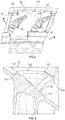
- a segment of the outer diameter platform 70 is viewed from a radially outward to inward perspective.
- the illustrated segment of the outer diameter platform 70 includes two adjacent stator vane locations, one of which is illustrated with the turn cover 100 operatively coupled thereto and the other having the turn cover 100 removed to illustrate a platform collar 102 that is integrally formed with the outer diameter platform 70 in a casting process.
- the turn cover 100 is affixed to the platform collar 102 using various manufacturing weld, and/or braze processes in some embodiments, but alternative joining methods are contemplated.
- the turn cover 100 is not integrally formed with the outer diameter platform 70, such as with a casting process, to avoid thick and stiff walls that create stress risers that are inherently present with the geometries of the relevant components.
- the platform collar 102, and the turn cover 100 that is operatively coupled thereto, is positioned adjacent to the inlet feed orifice 82 of the outer diameter platform 70, thereby allowing the cooling airflow 80 to enter the vane 27.
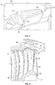
- the platform collar 102 is illustrated in greater detail.
- the platform collar 102 is a feature of the outer diameter platform 70 that extends radially outwardly from a main surface 104 of the outer diameter platform 70.
- the platform collar 102 does not have to extend to a common radial height, or to a uniform arcuate profile. Rather, the platform collar 102 is an angled collar that extends to different radially outward distances (i.e., non-uniform radial height). In particular, at least a portion of the platform collar 102 tilts at an angle to provide a lower height near the inlet feed orifice 82 of the platform collar 102.
- the corner of the platform collar 102 referenced with numeral 110 has a height 112 that is greater than a height 114 of the corner 116.
- the heights 112, 114 are measured from the main surface 104 of the outer diameter platform 70 to the radial position of the platform collar 102.
- the radially outer surface 118 of the platform collar 102 is the surface to which the turn cover 100 is welded and/or brazed to.
- the height of the platform collar 102 is high enough to have sufficient depth for welding the turn cover 100 to it.
- the radially outer surface 118 is flat (i.e., continuous planar surface) in some embodiments, but may be contoured in other embodiments to reduce stress.
- the radially outers surface 118 may be tailored to have either convex and/or concave curvature depending on local thermal strain requirements necessary to mitigate thermal mechanical fatigue (TMF) and/or low cycle fatigue (LCF) crack initiation and propagation.
- the turn cover 100 is illustrated in an installed condition.
- the turn cover 100 which is a component separately formed from the remainder of the vane assembly 27, including the outer diameter platform 102, is operatively coupled to the platform collar 102 in the manner described herein.
- the turn cover 100 is sheet metal in some embodiments and is contoured to create the serpentine turn on the top of the platform collar 102.
- the turn cover may be fabricated using standard forming tooling for sheet metal design and material applications, other manufacturing processes may be desirable and enable further design optimization to minimize internal flow separation resulting in undesirable pressure losses and poor internal convective heat transfer characteristics.
- Alternative turn cover design geometries may be fabricated using advanced additive manufacturing methods, such as a metal based powder laser sintering process, more commonly referred to as Direct Metal Laser Sintering (DMLS), or Select Laser Sintering (SLS).
- Additive manufacturing processes enable the turn cover design concepts to be more elaborate and specifically tailored by enabling the incorporation of geometric flow features and surface contours that may be unachievable using conventional sheet metal forming and joining processes.
- the offset distance and radial height of the platform collar 102 may vary non-uniformly, creating a nonplanar radial outward surface 118 in order to optimally tailor and minimize the local thermal-mechanical strain distribution that exists between the colder platform collar 102 and the hotter surrounding platform main surface 104 and inlet corner(s) of orifice 82.
- the radial outward surface 118 may also comprise of convex and/or convex surface curvatures used in conjunction with planar surfaces in order to mitigate locally high thermal-mechanical strains that may result in thermal mechanical fatigue (TMF) and/or low cycle fatigue (LCF) crack initiation and propagation.
- the higher corner(s) of the platform collar 102 provide sufficient depth for welding operations, represented by dash line 103 in Fig. 7 .
- the thick wall of a cast-in turn feature is replaced with the thin sheet metal turn cover 100, thereby reducing weight of the overall system.
Landscapes
- Engineering & Computer Science (AREA)
- Mechanical Engineering (AREA)
- General Engineering & Computer Science (AREA)
- Architecture (AREA)
- Physics & Mathematics (AREA)
- Fluid Mechanics (AREA)
- Turbine Rotor Nozzle Sealing (AREA)
Abstract
Description
- This application claims the benefit of
U.S. Provisional Application No. 62/731,395 filed September 14, 2018 - This invention was made with Government support under Contract No. FA8626-16-C-2139 awarded by the United States Air Force. The Government has certain rights in the invention.
- Exemplary embodiments pertain to the art of gas turbine engines and, more particularly, to a serpentine turn cover for gas turbine engines.
- Gas turbine engines typically include a compressor section, a combustor section, and a turbine section. During operation, air is pressurized in the compressor section and is mixed with fuel and burned in the combustor section to generate hot combustion gases. The hot combustion gases are communicated through the turbine section, which extracts energy from the hot combustion gases to power the compressor section and other gas turbine engine loads. Both the compressor and turbine sections may include alternating arrays of rotating blades and stationary vanes that extend into the core airflow path of the gas turbine engine. For example, in the turbine section, turbine blades rotate and extract energy from the hot combustion gases that are communicated along the core airflow path. The turbine vanes guide the airflow and prepare it for the downstream set of blades.
- Turbine vanes are known to include internal passageways configured to direct a flow of cooling fluid within the interior of the vane. The flow of cooling fluid protects the vane from the relatively hot fluid in the core airflow path. In order to reduce the amount of cooling flow needed to meet temperature requirements, the same cooling flow may be used to cool the platform of the vane and part of the airfoil itself. After cooling the platform, the cooling air must make its way to the inlet of the airfoil serpentine cooling passages. Inside the airfoil serpentine, the air will turn from the inner diameter to the outer diameter and make a final turn before dispersing into airfoil trailing edge discharge features.
- Serpentine passageways are formed within an interior of an airfoil section of the vane, and are often formed integrally with the remainder of the vane using an investment casting process, for example. However, cast-in serpentine turning features at the outer diameter of the airfoil are subject to high metal temperatures and the stress at the air inlet corners may be unacceptably high.
- According to a first aspect of the invention there is provided a stator vane assembly as recited in claim 1, including an inner diameter platform. The assembly also includes an outer diameter platform defining an air inlet orifice extending radially therethrough. Further included is an airfoil extending between the inner diameter platform and the outer diameter platform, the airfoil having a hollow portion therein defining a serpentine cooling airflow path fluidly coupled to the air inlet orifice. Yet further included is a collar extending radially outwardly from the outer diameter platform and positioned adjacent the air inlet orifice, the collar extending to a non-uniform radial distance. The assembly also includes a turn cover operatively coupled to the collar.
- Optionally, the turn cover is welded to the collar.
- Optionally, the turn cover is formed of sheet metal.
- Optionally, the airfoil, the outer diameter platform and the collar are integrally formed.
- Optionally, the airfoil, the outer diameter platform and the collar are formed from a casting process.
- Optionally, a radially outer surface of the collar is angled to include a most radially inward location.
- Optionally, the most radially inward location is located adjacent to the air inlet orifice.
- Optionally, the radially outer surface of the collar is a continuous planar surface.
- Optionally, the radially outer surface of the collar is contoured.
- Optionally, the radially outer surface of the collar is contoured to include at least one portion that is concave.
- Optionally, the radially outer surface of the collar is contoured to include at least one portion that is convex.
- According to a second aspect of the invention there is provided a gas turbine engine comprising: a compressor section; a combustor section; a turbine section; and a stator vane assembly as described herein with reference to the first aspect of the invention.
- According to a third aspect of the invention there is provided a gas turbine engine as recited in claim 8, including a compressor section, a combustor section, and a turbine section. Also included is a stator vane assembly located within the turbine section. The stator vane assembly includes an outer diameter platform defining an air inlet orifice extending radially therethrough. The stator vane assembly also includes an airfoil extending between the inner diameter platform and the outer diameter platform, the airfoil having a hollow portion therein defining a serpentine cooling airflow path fluidly coupled to the air inlet orifice. The stator vane assembly further includes a turn cover welded to the outer diameter platform adjacent to the air inlet orifice.
- Optionally, further embodiments may include a collar extending radially outwardly from the outer diameter platform, the turn cover welded to a radially outer surface of the collar.
- Optionally, the collar extends to a non-uniform radial distance.
- Optionally, the collar extends to a uniform radial distance.
- Optionally, the airfoil, the outer diameter platform and the collar are integrally formed.
- Optionally, the radially outer surface of the collar is angled to include a most radially inward location.
- Optionally, the radially outer surface of the collar is flat.
- Optionally, the radially outer surface of the collar is contoured.
- Optionally, the gas turbine engine comprises a stator vane assembly as recited herein with reference to the first aspect of the invention.
- According to a fourth aspect of the invention there is provided a method of assembling a stator vane assembly for a gas turbine engine as recited in claim 15. The method includes integrally forming a stator vane and an outer diameter platform, the stator vane having a hollow portion therein defining a serpentine cooling airflow path fluidly coupled to an air inlet orifice of the outer diameter platform. The method also includes welding a turn cover to the outer diameter platform adjacent to the air inlet orifice.
- Optionally, the method includes assembling a stator vane assembly as recited herein with reference to the first aspect of the invention, and/or includes assembling a gas turbine engine as recited herein with reference to the second aspect of the invention or the third aspect of the invention.
- The following descriptions should not be considered limiting in any way. With reference to the accompanying drawings, like elements are numbered alike:
-
FIG. 1 is a side, partial cross-sectional view of a gas turbine engine; -
FIG. 2 is a schematic illustration of a portion of the gas turbine engine showing rotor assemblies and a stator vane assembly; -
FIG. 3 is a perspective view of an outer diameter of a stator platform of the stator vane assembly; -
FIG. 4 is a cross-sectional view of a platform collar taken along line A-A ofFIG. 3 ; -
FIG. 5 is a perspective view of the platform collar; -
FIG. 6 is a cross-sectional view of a turn cover taken along line B-B ofFIG. 3 ; -
FIG. 7 is an enlarged view of the sectional view ofFIG. 6 of the turn cover; and -
FIG. 8 is a perspective view of the turn cover. - A detailed description of one or more embodiments of the disclosed apparatus and method are presented herein by way of exemplification and not limitation with reference to the Figures.
-
FIG. 1 schematically illustrates agas turbine engine 20. Thegas turbine engine 20 is disclosed herein as a two-spool turbofan that generally incorporates afan section 22, acompressor section 24, acombustor section 26 and aturbine section 28. Thefan section 22 drives air along a bypass flow path B in a bypass duct, while thecompressor section 24 drives air along a core flow path C for compression and communication into thecombustor section 26 then expansion through theturbine section 28. Although depicted as a two-spool turbofan gas turbine engine in the disclosed non-limiting embodiment, it should be understood that the concepts described herein are not limited to use with two-spool turbofans as the teachings may be applied to other types of turbine engines including three-spool architectures. - The
exemplary engine 20 generally includes alow speed spool 30 and ahigh speed spool 32 mounted for rotation about an engine central longitudinal axis A relative to an enginestatic structure 36 viaseveral bearing systems 38. It should be understood that various bearingsystems 38 at various locations may alternatively or additionally be provided, and the location of bearingsystems 38 may be varied as appropriate to the application. - The
low speed spool 30 generally includes aninner shaft 40 that interconnects afan 42, alow pressure compressor 44 and alow pressure turbine 46. Theinner shaft 40 is connected to thefan 42 through a speed change mechanism, which in exemplarygas turbine engine 20 is illustrated as a gearedarchitecture 48 to drive thefan 42 at a lower speed than thelow speed spool 30. Thehigh speed spool 32 includes anouter shaft 50 that interconnects ahigh pressure compressor 52 andhigh pressure turbine 54. Acombustor 56 is arranged inexemplary gas turbine 20 between thehigh pressure compressor 52 and thehigh pressure turbine 54. An enginestatic structure 36 is arranged generally between thehigh pressure turbine 54 and thelow pressure turbine 46. The enginestatic structure 36 furthersupports bearing systems 38 in theturbine section 28. Theinner shaft 40 and theouter shaft 50 are concentric and rotate via bearingsystems 38 about the engine central longitudinal axis A which is collinear with their longitudinal axes. - The core airflow is compressed by the
low pressure compressor 44 then thehigh pressure compressor 52, mixed and burned with fuel in thecombustor 56, then expanded over thehigh pressure turbine 54 andlow pressure turbine 46. Theturbines low speed spool 30 andhigh speed spool 32 in response to the expansion. It will be appreciated that each of the positions of thefan section 22,compressor section 24,combustor section 26,turbine section 28, and fandrive gear system 48 may be varied. For example,gear system 48 may be located aft ofcombustor section 26 or even aft ofturbine section 28, andfan section 22 may be positioned forward or aft of the location ofgear system 48. - The
engine 20 in one example is a high-bypass geared aircraft engine. In a further example, theengine 20 bypass ratio is greater than about six (6), with an example embodiment being greater than about ten (10), the gearedarchitecture 48 is an epicyclic gear train, such as a planetary gear system or other gear system, with a gear reduction ratio of greater than about 2.3 and thelow pressure turbine 46 has a pressure ratio that is greater than about five. In one disclosed embodiment, theengine 20 bypass ratio is greater than about ten (10:1), the fan diameter is significantly larger than that of thelow pressure compressor 44, and thelow pressure turbine 46 has a pressure ratio that is greater than about five (5:1).Low pressure turbine 46 pressure ratio is pressure measured prior to inlet oflow pressure turbine 46 as related to the pressure at the outlet of thelow pressure turbine 46 prior to an exhaust nozzle. The gearedarchitecture 48 may be an epicycle gear train, such as a planetary gear system or other gear system, with a gear reduction ratio of greater than about 2.3:1. It should be understood, however, that the above parameters are only exemplary of one embodiment of a geared architecture engine and that the present disclosure is applicable to other gas turbine engines including direct drive turbofans. - A significant amount of thrust is provided by the bypass flow B due to the high bypass ratio. The
fan section 22 of theengine 20 is designed for a particular flight condition--typically cruise at about 0.8 Mach and about 35,000 feet (10,688 meters). The flight condition of 0.8 Mach and 35,000 feet (10,688 meters), with the engine at its best fuel consumption--also known as "bucket cruise Thrust Specific Fuel Consumption ('TSFC)"--is the industry standard parameter of lbm of fuel being burned divided by lbf of thrust the engine produces at that minimum point. "Low fan pressure ratio" is the pressure ratio across the fan blade alone, without a Fan Exit Guide Vane ("FEGV") system. The low fan pressure ratio as disclosed herein according to one non-limiting embodiment is less than about 1.45. "Low corrected fan tip speed" is the actual fan tip speed in ft/sec divided by an industry standard temperature correction of [(Tram °R)/(518.7 °R)]0.5. The "Low corrected fan tip speed" as disclosed herein according to one non-limiting embodiment is less than about 1150 ft/second (350.5 m/sec). - Each of the
compressor section 24 and theturbine section 28 may include alternating rows of rotor assemblies and vane assemblies (shown schematically) that carry airfoils that extend into the core flow path C. For example, the rotor assemblies can carry a plurality of rotating blades 25 (FIG. 2 ), while each vane assembly can carry a plurality ofvanes 27 that extend into the core flow path C. Theblades 25 of the rotor assemblies create or extract energy (in the form of pressure) from the core airflow that is communicated through thegas turbine engine 20 along the core flow path C. Thevanes 27 of the vane assemblies direct the core airflow to theblades 25 to either add or extract energy. - Various components of the
gas turbine engine 20, including but not limited to the airfoils of theblades 25 and thevanes 27 of thecompressor section 24 and theturbine section 28, may be subjected to repetitive thermal cycling under widely ranging temperatures and pressures. The hardware of theturbine section 28 is particularly subjected to relatively extreme operating conditions. Therefore, some components may require internal cooling circuits for cooling the parts during engine operation. -
FIG. 2 is a partial schematic view of theturbine section 28. As described above, theturbine section 28 includes airfoils in the form of stationarystator vane assemblies 27 and other airfoils that areblades 25 of turbines disks. The illustratedstator vane assembly 27 is an airfoil with one or more internal cavities 60 (FIG. 6 ) defining a number of cooling passages. The airfoil cavities 60 are formed within the airfoil and are at least partially defined bypartitions 62 that extend either from aninner diameter 64 or anouter diameter 68 of thevane 27. Thepartitions 62, as shown, extend for a portion of the internal radial distance of thevane 27 to form a serpentine passage within thevane 27. As such, thepartitions 62 may stop or end prior to forming a complete wall within thevane 27. Thus, each of theairfoil cavities 60 may be fluidly connected. - The
vane 27 includes anouter diameter platform 70 and aninner diameter platform 72. Thevane platforms gas turbine engine 20. For example, as appreciated by those of skill in the art, theinner diameter platform 72 can be mounted betweenadjacent rotor disks 74 and theouter diameter platform 70 can be mounted to acase 76 of thegas turbine engine 20. As shown, anouter diameter cavity 78 is formed between thecase 76 and theouter diameter platform 70. Theouter diameter cavity 78 is outside of, or separate from, the core flow path C. The body of thevane 27 extends from and between surfaces of therespective platforms platforms vane 27 are a unitary body. - Air is passed through the
airfoil cooling cavities 60 of thevane 27 to provide cooling airflow to prevent overheating of the airfoils and/or other components or parts of thegas turbine engine 20. The airfoil cavities 60 are configured to have air flow therethrough to cool thevane 27. For example, as shown inFIG. 6 , anairflow path 80 is indicated by a dashed line. In the configuration ofFIG. 6 , air flows from theouter diameter cavity 78 and into theairfoil cooling cavities 60 through aninlet feed orifice 82 defined by theouter diameter platform 70. The air then flows into and through theairfoil cooling cavities 60 as indicated by theairflow path 80. Aturn cover 100 is operatively coupled (welding or brazing, for example) to theouter diameter platform 70 to facilitate turning of theairflow 80, as described in detail herein. - Referring now to
FIG. 3 , a segment of theouter diameter platform 70 is viewed from a radially outward to inward perspective. The illustrated segment of theouter diameter platform 70 includes two adjacent stator vane locations, one of which is illustrated with theturn cover 100 operatively coupled thereto and the other having theturn cover 100 removed to illustrate aplatform collar 102 that is integrally formed with theouter diameter platform 70 in a casting process. Theturn cover 100 is affixed to theplatform collar 102 using various manufacturing weld, and/or braze processes in some embodiments, but alternative joining methods are contemplated. However, theturn cover 100 is not integrally formed with theouter diameter platform 70, such as with a casting process, to avoid thick and stiff walls that create stress risers that are inherently present with the geometries of the relevant components. - The
platform collar 102, and theturn cover 100 that is operatively coupled thereto, is positioned adjacent to theinlet feed orifice 82 of theouter diameter platform 70, thereby allowing the coolingairflow 80 to enter thevane 27. - Referring to
FIGS. 4 and5 , theplatform collar 102 is illustrated in greater detail. Theplatform collar 102 is a feature of theouter diameter platform 70 that extends radially outwardly from amain surface 104 of theouter diameter platform 70. Theplatform collar 102 does not have to extend to a common radial height, or to a uniform arcuate profile. Rather, theplatform collar 102 is an angled collar that extends to different radially outward distances (i.e., non-uniform radial height). In particular, at least a portion of theplatform collar 102 tilts at an angle to provide a lower height near theinlet feed orifice 82 of theplatform collar 102. As shown, the corner of theplatform collar 102 referenced withnumeral 110 has aheight 112 that is greater than aheight 114 of thecorner 116. Theheights main surface 104 of theouter diameter platform 70 to the radial position of theplatform collar 102. - The radially
outer surface 118 of theplatform collar 102 is the surface to which theturn cover 100 is welded and/or brazed to. The height of theplatform collar 102 is high enough to have sufficient depth for welding theturn cover 100 to it. The radiallyouter surface 118 is flat (i.e., continuous planar surface) in some embodiments, but may be contoured in other embodiments to reduce stress. In an embodiment with a contoured radially outer surface that does not include a continuous planar surface, the radially outers surface 118 may be tailored to have either convex and/or concave curvature depending on local thermal strain requirements necessary to mitigate thermal mechanical fatigue (TMF) and/or low cycle fatigue (LCF) crack initiation and propagation. - Referring to
FIGS. 6-8 , theturn cover 100 is illustrated in an installed condition. In particular, theturn cover 100 which is a component separately formed from the remainder of thevane assembly 27, including theouter diameter platform 102, is operatively coupled to theplatform collar 102 in the manner described herein. Theturn cover 100 is sheet metal in some embodiments and is contoured to create the serpentine turn on the top of theplatform collar 102. Although the turn cover may be fabricated using standard forming tooling for sheet metal design and material applications, other manufacturing processes may be desirable and enable further design optimization to minimize internal flow separation resulting in undesirable pressure losses and poor internal convective heat transfer characteristics. Alternative turn cover design geometries may be fabricated using advanced additive manufacturing methods, such as a metal based powder laser sintering process, more commonly referred to as Direct Metal Laser Sintering (DMLS), or Select Laser Sintering (SLS). Additive manufacturing processes enable the turn cover design concepts to be more elaborate and specifically tailored by enabling the incorporation of geometric flow features and surface contours that may be unachievable using conventional sheet metal forming and joining processes. - With traditional cast-in serpentine turns and high metal temperatures on the
vane 27, the stress at the air inlet corner(s) oforifice 82 is much higher when compared to the embodiments described herein. Removing the cast-in turn results in a collar-cover configuration serves as a conduit that turns and redirects the internal cooling air flow to downstream cooling passages in order maximize the convective and thermal efficiency of overall cooling configuration. Theangled platform collar 102 described herein, with its lowered height near theorifice 82 corner, yields a significantly lower stress at that region by reducing and minimizing the local "stiffness" and thermal strain between the relativelycolder platform collar 102 walls and the hotter surrounding platformmain surface 104 of theouter diameter platform 70. In an alternative embodiment the offset distance and radial height of theplatform collar 102 may vary non-uniformly, creating a nonplanar radialoutward surface 118 in order to optimally tailor and minimize the local thermal-mechanical strain distribution that exists between thecolder platform collar 102 and the hotter surrounding platformmain surface 104 and inlet corner(s) oforifice 82. The radialoutward surface 118 may also comprise of convex and/or convex surface curvatures used in conjunction with planar surfaces in order to mitigate locally high thermal-mechanical strains that may result in thermal mechanical fatigue (TMF) and/or low cycle fatigue (LCF) crack initiation and propagation. - The higher corner(s) of the
platform collar 102 provide sufficient depth for welding operations, represented bydash line 103 inFig. 7 . In addition to the stress reduction, the thick wall of a cast-in turn feature is replaced with the thin sheetmetal turn cover 100, thereby reducing weight of the overall system. - The term "about" is intended to include the degree of error associated with measurement of the particular quantity based upon the equipment available at the time of filing the application. For example, "about" can include a range of ± 8% or 5%, or 2% of a given value.
- The terminology used herein is for the purpose of describing particular embodiments only and is not intended to be limiting of the present disclosure. As used herein, the singular forms "a", "an" and "the" are intended to include the plural forms as well, unless the context clearly indicates otherwise. It will be further understood that the terms "comprises" and/or "comprising," when used in this specification, specify the presence of stated features, integers, steps, operations, elements, and/or components, but do not preclude the presence or addition of one or more other features, integers, steps, operations, element components, and/or groups thereof.
- While the present disclosure has been described with reference to an exemplary embodiment or embodiments, it will be understood by those skilled in the art that various changes may be made and equivalents may be substituted for elements thereof without departing from the scope of the present invention as defined by the appended claims. In addition, many modifications may be made to adapt a particular situation or material to the teachings of the present disclosure without departing from the scope of the invention. Therefore, it is intended that the present disclosure not be limited to the particular embodiment disclosed as the best mode contemplated for carrying out this present disclosure, but that the present disclosure will include all embodiments falling within the scope of the claims.
Claims (15)
- A stator vane assembly comprising:an inner diameter platform;an outer diameter platform defining an air inlet orifice extending radially therethrough;an airfoil extending between the inner diameter platform and the outer diameter platform, the airfoil having a hollow portion therein defining a serpentine cooling airflow path fluidly coupled to the air inlet orifice;a collar extending radially outwardly from the outer diameter platform and positioned adjacent the air inlet orifice, the collar extending to a non-uniform radial distance; anda turn cover operatively coupled to the collar.
- The stator vane assembly of claim 1, wherein the turn cover is welded to the collar.
- The stator vane assembly of claim 1 or 2, wherein the turn cover is formed of sheet metal.
- The stator vane assembly of claim 1, 2 or 3, wherein the airfoil, the outer diameter platform and the collar are integrally formed; preferably
wherein the airfoil, the outer diameter platform and the collar are formed from a casting process. - The stator vane assembly of any preceding claim, wherein a radially outer surface of the collar is angled to include a most radially inward location; and/or
wherein the most radially inward location is located adjacent to the air inlet orifice. - The stator vane assembly of any preceding claim, wherein the radially outer surface of the collar is a continuous planar surface.
- The stator vane assembly of any preceding claim, wherein the radially outer surface of the collar is contoured; preferably
wherein the radially outer surface of the collar is contoured to include at least one portion that is concave; or
wherein the radially outer surface of the collar is contoured to include at least one portion that is convex. - A gas turbine engine comprising:a compressor section;a combustor section;a turbine section; anda stator vane assembly located within the turbine section, the stator vane assembly comprising:an outer diameter platform defining an air inlet orifice extending radially therethrough;an airfoil extending between an inner diameter platform and the outer diameter platform, the airfoil having a hollow portion therein defining a serpentine cooling airflow path fluidly coupled to the air inlet orifice; anda turn cover welded to the outer diameter platform adjacent to the air inlet orifice.
- The gas turbine engine of claim 8, further comprising a collar extending radially outwardly from the outer diameter platform, the turn cover welded to a radially outer surface of the collar.
- The gas turbine engine of claim 9, wherein the collar extends to a non-uniform radial distance.
- The gas turbine engine of claim 9, wherein the collar extends to a uniform radial distance.
- The gas turbine engine of claim 9, 10 or 11, wherein the airfoil, the outer diameter platform and the collar are integrally formed.
- The gas turbine engine of any of claims 9 to 12, wherein the radially outer surface of the collar is angled to include a most radially inward location.
- The gas turbine engine of any of claims 9 to 13, wherein the radially outer surface of the collar is flat; or
wherein the radially outer surface of the collar is contoured. - A method of assembling a stator vane assembly for a gas turbine engine, the method comprising:integrally forming a stator vane and an outer diameter platform, the stator vane having a hollow portion therein defining a serpentine cooling airflow path fluidly coupled to an air inlet orifice of the outer diameter platform; andwelding a turn cover to the outer diameter platform adjacent to the air inlet orifice.
Applications Claiming Priority (2)
| Application Number | Priority Date | Filing Date | Title |
|---|---|---|---|
| US201862731395P | 2018-09-14 | 2018-09-14 | |
| US16/159,149 US10968746B2 (en) | 2018-09-14 | 2018-10-12 | Serpentine turn cover for gas turbine stator vane assembly |
Publications (2)
| Publication Number | Publication Date |
|---|---|
| EP3623575A1 true EP3623575A1 (en) | 2020-03-18 |
| EP3623575B1 EP3623575B1 (en) | 2021-11-17 |
Family
ID=67184923
Family Applications (1)
| Application Number | Title | Priority Date | Filing Date |
|---|---|---|---|
| EP19184771.4A Active EP3623575B1 (en) | 2018-09-14 | 2019-07-05 | Serpentine turn cover for gas turbine stator vane assembly |
Country Status (2)
| Country | Link |
|---|---|
| US (1) | US10968746B2 (en) |
| EP (1) | EP3623575B1 (en) |
Citations (3)
| Publication number | Priority date | Publication date | Assignee | Title |
|---|---|---|---|---|
| US20120148383A1 (en) * | 2010-12-14 | 2012-06-14 | Gear Paul J | Gas turbine vane with cooling channel end turn structure |
| WO2014165518A1 (en) * | 2013-04-01 | 2014-10-09 | United Technologies Corporation | Stator vane arrangement for a turbine engine |
| EP3348787A1 (en) * | 2017-01-12 | 2018-07-18 | United Technologies Corporation | Airfoil turn caps in gas turbine engines |
Family Cites Families (5)
| Publication number | Priority date | Publication date | Assignee | Title |
|---|---|---|---|---|
| US7108479B2 (en) * | 2003-06-19 | 2006-09-19 | General Electric Company | Methods and apparatus for supplying cooling fluid to turbine nozzles |
| US7445432B2 (en) * | 2006-03-28 | 2008-11-04 | United Technologies Corporation | Enhanced serpentine cooling with U-shaped divider rib |
| US8870524B1 (en) * | 2011-05-21 | 2014-10-28 | Florida Turbine Technologies, Inc. | Industrial turbine stator vane |
| US9845694B2 (en) | 2015-04-22 | 2017-12-19 | United Technologies Corporation | Flow directing cover for engine component |
| US10465528B2 (en) * | 2017-02-07 | 2019-11-05 | United Technologies Corporation | Airfoil turn caps in gas turbine engines |
-
2018
- 2018-10-12 US US16/159,149 patent/US10968746B2/en active Active
-
2019
- 2019-07-05 EP EP19184771.4A patent/EP3623575B1/en active Active
Patent Citations (3)
| Publication number | Priority date | Publication date | Assignee | Title |
|---|---|---|---|---|
| US20120148383A1 (en) * | 2010-12-14 | 2012-06-14 | Gear Paul J | Gas turbine vane with cooling channel end turn structure |
| WO2014165518A1 (en) * | 2013-04-01 | 2014-10-09 | United Technologies Corporation | Stator vane arrangement for a turbine engine |
| EP3348787A1 (en) * | 2017-01-12 | 2018-07-18 | United Technologies Corporation | Airfoil turn caps in gas turbine engines |
Also Published As
| Publication number | Publication date |
|---|---|
| US20200088038A1 (en) | 2020-03-19 |
| EP3623575B1 (en) | 2021-11-17 |
| US10968746B2 (en) | 2021-04-06 |
Similar Documents
| Publication | Publication Date | Title |
|---|---|---|
| EP2975217B1 (en) | Using inserts to balance heat transfer and stress in high temperature alloys | |
| US11035236B2 (en) | Baffle for a component of a gas turbine engine | |
| EP2993304B1 (en) | Gas turbine engine component with film cooling hole | |
| EP3054094B1 (en) | Gas turbine engine turbine vane baffle and serpentine cooling passage | |
| EP3252420A1 (en) | Heat exchanger with precision manufactured flow passages | |
| US11976566B2 (en) | Fatigue resistant blade outer air seal | |
| EP3078807B2 (en) | Cooling passages for a gas turbine engine component | |
| EP3112596A1 (en) | Gas turbine engine airfoil with bi-axial skin cooling passage and corresponding gas turbine engine | |
| EP3047111B1 (en) | Component for a gas turbine engine, corresponding gas turbine engine and method of cooling | |
| EP3514331B1 (en) | Cooled airfoil and corresponding gas turbine engine | |
| EP3502420B1 (en) | Component for a gas turbine engine and corresponding gas turbine engine | |
| EP3564485B1 (en) | Airfoils, cores, and methods of manufacture for forming airfoils having fluidly connected platform cooling circuits | |
| EP3623575B1 (en) | Serpentine turn cover for gas turbine stator vane assembly | |
| EP3045666B1 (en) | Airfoil platform with cooling feed orifices | |
| EP3708776A1 (en) | Gasturbine airfoils having tapered tip flag cavity and cores for forming the same | |
| EP3748133B1 (en) | Fatigue resistant blade outer air seal | |
| EP3569819B1 (en) | Multiple source impingement baffles for gas turbine engine components | |
| EP3663517B1 (en) | Component for a gas turbine engine and corresponding gas turbine engine |
Legal Events
| Date | Code | Title | Description |
|---|---|---|---|
| PUAI | Public reference made under article 153(3) epc to a published international application that has entered the european phase |
Free format text: ORIGINAL CODE: 0009012 |
|
| STAA | Information on the status of an ep patent application or granted ep patent |
Free format text: STATUS: THE APPLICATION HAS BEEN PUBLISHED |
|
| AK | Designated contracting states |
Kind code of ref document: A1 Designated state(s): AL AT BE BG CH CY CZ DE DK EE ES FI FR GB GR HR HU IE IS IT LI LT LU LV MC MK MT NL NO PL PT RO RS SE SI SK SM TR |
|
| AX | Request for extension of the european patent |
Extension state: BA ME |
|
| STAA | Information on the status of an ep patent application or granted ep patent |
Free format text: STATUS: REQUEST FOR EXAMINATION WAS MADE |
|
| 17P | Request for examination filed |
Effective date: 20200918 |
|
| RBV | Designated contracting states (corrected) |
Designated state(s): AL AT BE BG CH CY CZ DE DK EE ES FI FR GB GR HR HU IE IS IT LI LT LU LV MC MK MT NL NO PL PT RO RS SE SI SK SM TR |
|
| GRAP | Despatch of communication of intention to grant a patent |
Free format text: ORIGINAL CODE: EPIDOSNIGR1 |
|
| STAA | Information on the status of an ep patent application or granted ep patent |
Free format text: STATUS: GRANT OF PATENT IS INTENDED |
|
| INTG | Intention to grant announced |
Effective date: 20201209 |
|
| RAP1 | Party data changed (applicant data changed or rights of an application transferred) |
Owner name: RAYTHEON TECHNOLOGIES CORPORATION |
|
| GRAJ | Information related to disapproval of communication of intention to grant by the applicant or resumption of examination proceedings by the epo deleted |
Free format text: ORIGINAL CODE: EPIDOSDIGR1 |
|
| STAA | Information on the status of an ep patent application or granted ep patent |
Free format text: STATUS: REQUEST FOR EXAMINATION WAS MADE |
|
| INTC | Intention to grant announced (deleted) | ||
| GRAP | Despatch of communication of intention to grant a patent |
Free format text: ORIGINAL CODE: EPIDOSNIGR1 |
|
| STAA | Information on the status of an ep patent application or granted ep patent |
Free format text: STATUS: GRANT OF PATENT IS INTENDED |
|
| INTG | Intention to grant announced |
Effective date: 20210621 |
|
| RIN1 | Information on inventor provided before grant (corrected) |
Inventor name: VU, KY H. Inventor name: MONGILLO, DOMINIC J. |
|
| GRAS | Grant fee paid |
Free format text: ORIGINAL CODE: EPIDOSNIGR3 |
|
| GRAA | (expected) grant |
Free format text: ORIGINAL CODE: 0009210 |
|
| STAA | Information on the status of an ep patent application or granted ep patent |
Free format text: STATUS: THE PATENT HAS BEEN GRANTED |
|
| AK | Designated contracting states |
Kind code of ref document: B1 Designated state(s): AL AT BE BG CH CY CZ DE DK EE ES FI FR GB GR HR HU IE IS IT LI LT LU LV MC MK MT NL NO PL PT RO RS SE SI SK SM TR |
|
| REG | Reference to a national code |
Ref country code: GB Ref legal event code: FG4D |
|
| REG | Reference to a national code |
Ref country code: IE Ref legal event code: FG4D |
|
| REG | Reference to a national code |
Ref country code: DE Ref legal event code: R096 Ref document number: 602019009309 Country of ref document: DE |
|
| REG | Reference to a national code |
Ref country code: AT Ref legal event code: REF Ref document number: 1448211 Country of ref document: AT Kind code of ref document: T Effective date: 20211215 |
|
| REG | Reference to a national code |
Ref country code: LT Ref legal event code: MG9D |
|
| REG | Reference to a national code |
Ref country code: NL Ref legal event code: MP Effective date: 20211117 |
|
| REG | Reference to a national code |
Ref country code: AT Ref legal event code: MK05 Ref document number: 1448211 Country of ref document: AT Kind code of ref document: T Effective date: 20211117 |
|
| PG25 | Lapsed in a contracting state [announced via postgrant information from national office to epo] |
Ref country code: RS Free format text: LAPSE BECAUSE OF FAILURE TO SUBMIT A TRANSLATION OF THE DESCRIPTION OR TO PAY THE FEE WITHIN THE PRESCRIBED TIME-LIMIT Effective date: 20211117 Ref country code: LT Free format text: LAPSE BECAUSE OF FAILURE TO SUBMIT A TRANSLATION OF THE DESCRIPTION OR TO PAY THE FEE WITHIN THE PRESCRIBED TIME-LIMIT Effective date: 20211117 Ref country code: FI Free format text: LAPSE BECAUSE OF FAILURE TO SUBMIT A TRANSLATION OF THE DESCRIPTION OR TO PAY THE FEE WITHIN THE PRESCRIBED TIME-LIMIT Effective date: 20211117 Ref country code: BG Free format text: LAPSE BECAUSE OF FAILURE TO SUBMIT A TRANSLATION OF THE DESCRIPTION OR TO PAY THE FEE WITHIN THE PRESCRIBED TIME-LIMIT Effective date: 20220217 Ref country code: AT Free format text: LAPSE BECAUSE OF FAILURE TO SUBMIT A TRANSLATION OF THE DESCRIPTION OR TO PAY THE FEE WITHIN THE PRESCRIBED TIME-LIMIT Effective date: 20211117 |
|
| PG25 | Lapsed in a contracting state [announced via postgrant information from national office to epo] |
Ref country code: IS Free format text: LAPSE BECAUSE OF FAILURE TO SUBMIT A TRANSLATION OF THE DESCRIPTION OR TO PAY THE FEE WITHIN THE PRESCRIBED TIME-LIMIT Effective date: 20220317 Ref country code: SE Free format text: LAPSE BECAUSE OF FAILURE TO SUBMIT A TRANSLATION OF THE DESCRIPTION OR TO PAY THE FEE WITHIN THE PRESCRIBED TIME-LIMIT Effective date: 20211117 Ref country code: PT Free format text: LAPSE BECAUSE OF FAILURE TO SUBMIT A TRANSLATION OF THE DESCRIPTION OR TO PAY THE FEE WITHIN THE PRESCRIBED TIME-LIMIT Effective date: 20220317 Ref country code: PL Free format text: LAPSE BECAUSE OF FAILURE TO SUBMIT A TRANSLATION OF THE DESCRIPTION OR TO PAY THE FEE WITHIN THE PRESCRIBED TIME-LIMIT Effective date: 20211117 Ref country code: NO Free format text: LAPSE BECAUSE OF FAILURE TO SUBMIT A TRANSLATION OF THE DESCRIPTION OR TO PAY THE FEE WITHIN THE PRESCRIBED TIME-LIMIT Effective date: 20220217 Ref country code: NL Free format text: LAPSE BECAUSE OF FAILURE TO SUBMIT A TRANSLATION OF THE DESCRIPTION OR TO PAY THE FEE WITHIN THE PRESCRIBED TIME-LIMIT Effective date: 20211117 Ref country code: LV Free format text: LAPSE BECAUSE OF FAILURE TO SUBMIT A TRANSLATION OF THE DESCRIPTION OR TO PAY THE FEE WITHIN THE PRESCRIBED TIME-LIMIT Effective date: 20211117 Ref country code: HR Free format text: LAPSE BECAUSE OF FAILURE TO SUBMIT A TRANSLATION OF THE DESCRIPTION OR TO PAY THE FEE WITHIN THE PRESCRIBED TIME-LIMIT Effective date: 20211117 Ref country code: GR Free format text: LAPSE BECAUSE OF FAILURE TO SUBMIT A TRANSLATION OF THE DESCRIPTION OR TO PAY THE FEE WITHIN THE PRESCRIBED TIME-LIMIT Effective date: 20220218 Ref country code: ES Free format text: LAPSE BECAUSE OF FAILURE TO SUBMIT A TRANSLATION OF THE DESCRIPTION OR TO PAY THE FEE WITHIN THE PRESCRIBED TIME-LIMIT Effective date: 20211117 |
|
| PG25 | Lapsed in a contracting state [announced via postgrant information from national office to epo] |
Ref country code: SM Free format text: LAPSE BECAUSE OF FAILURE TO SUBMIT A TRANSLATION OF THE DESCRIPTION OR TO PAY THE FEE WITHIN THE PRESCRIBED TIME-LIMIT Effective date: 20211117 Ref country code: SK Free format text: LAPSE BECAUSE OF FAILURE TO SUBMIT A TRANSLATION OF THE DESCRIPTION OR TO PAY THE FEE WITHIN THE PRESCRIBED TIME-LIMIT Effective date: 20211117 Ref country code: RO Free format text: LAPSE BECAUSE OF FAILURE TO SUBMIT A TRANSLATION OF THE DESCRIPTION OR TO PAY THE FEE WITHIN THE PRESCRIBED TIME-LIMIT Effective date: 20211117 Ref country code: EE Free format text: LAPSE BECAUSE OF FAILURE TO SUBMIT A TRANSLATION OF THE DESCRIPTION OR TO PAY THE FEE WITHIN THE PRESCRIBED TIME-LIMIT Effective date: 20211117 Ref country code: DK Free format text: LAPSE BECAUSE OF FAILURE TO SUBMIT A TRANSLATION OF THE DESCRIPTION OR TO PAY THE FEE WITHIN THE PRESCRIBED TIME-LIMIT Effective date: 20211117 Ref country code: CZ Free format text: LAPSE BECAUSE OF FAILURE TO SUBMIT A TRANSLATION OF THE DESCRIPTION OR TO PAY THE FEE WITHIN THE PRESCRIBED TIME-LIMIT Effective date: 20211117 |
|
| REG | Reference to a national code |
Ref country code: DE Ref legal event code: R097 Ref document number: 602019009309 Country of ref document: DE |
|
| PLBE | No opposition filed within time limit |
Free format text: ORIGINAL CODE: 0009261 |
|
| STAA | Information on the status of an ep patent application or granted ep patent |
Free format text: STATUS: NO OPPOSITION FILED WITHIN TIME LIMIT |
|
| 26N | No opposition filed |
Effective date: 20220818 |
|
| PG25 | Lapsed in a contracting state [announced via postgrant information from national office to epo] |
Ref country code: AL Free format text: LAPSE BECAUSE OF FAILURE TO SUBMIT A TRANSLATION OF THE DESCRIPTION OR TO PAY THE FEE WITHIN THE PRESCRIBED TIME-LIMIT Effective date: 20211117 |
|
| PG25 | Lapsed in a contracting state [announced via postgrant information from national office to epo] |
Ref country code: SI Free format text: LAPSE BECAUSE OF FAILURE TO SUBMIT A TRANSLATION OF THE DESCRIPTION OR TO PAY THE FEE WITHIN THE PRESCRIBED TIME-LIMIT Effective date: 20211117 |
|
| PG25 | Lapsed in a contracting state [announced via postgrant information from national office to epo] |
Ref country code: MC Free format text: LAPSE BECAUSE OF FAILURE TO SUBMIT A TRANSLATION OF THE DESCRIPTION OR TO PAY THE FEE WITHIN THE PRESCRIBED TIME-LIMIT Effective date: 20211117 |
|
| REG | Reference to a national code |
Ref country code: CH Ref legal event code: PL |
|
| REG | Reference to a national code |
Ref country code: BE Ref legal event code: MM Effective date: 20220731 |
|
| PG25 | Lapsed in a contracting state [announced via postgrant information from national office to epo] |
Ref country code: LU Free format text: LAPSE BECAUSE OF NON-PAYMENT OF DUE FEES Effective date: 20220705 Ref country code: LI Free format text: LAPSE BECAUSE OF NON-PAYMENT OF DUE FEES Effective date: 20220731 Ref country code: CH Free format text: LAPSE BECAUSE OF NON-PAYMENT OF DUE FEES Effective date: 20220731 |
|
| PG25 | Lapsed in a contracting state [announced via postgrant information from national office to epo] |
Ref country code: IT Free format text: LAPSE BECAUSE OF FAILURE TO SUBMIT A TRANSLATION OF THE DESCRIPTION OR TO PAY THE FEE WITHIN THE PRESCRIBED TIME-LIMIT Effective date: 20211117 Ref country code: BE Free format text: LAPSE BECAUSE OF NON-PAYMENT OF DUE FEES Effective date: 20220731 |
|
| P01 | Opt-out of the competence of the unified patent court (upc) registered |
Effective date: 20230521 |
|
| PG25 | Lapsed in a contracting state [announced via postgrant information from national office to epo] |
Ref country code: IE Free format text: LAPSE BECAUSE OF NON-PAYMENT OF DUE FEES Effective date: 20220705 |
|
| PGFP | Annual fee paid to national office [announced via postgrant information from national office to epo] |
Ref country code: DE Payment date: 20230620 Year of fee payment: 5 |
|
| PG25 | Lapsed in a contracting state [announced via postgrant information from national office to epo] |
Ref country code: HU Free format text: LAPSE BECAUSE OF FAILURE TO SUBMIT A TRANSLATION OF THE DESCRIPTION OR TO PAY THE FEE WITHIN THE PRESCRIBED TIME-LIMIT; INVALID AB INITIO Effective date: 20190705 |
|
| PG25 | Lapsed in a contracting state [announced via postgrant information from national office to epo] |
Ref country code: MK Free format text: LAPSE BECAUSE OF FAILURE TO SUBMIT A TRANSLATION OF THE DESCRIPTION OR TO PAY THE FEE WITHIN THE PRESCRIBED TIME-LIMIT Effective date: 20211117 Ref country code: CY Free format text: LAPSE BECAUSE OF FAILURE TO SUBMIT A TRANSLATION OF THE DESCRIPTION OR TO PAY THE FEE WITHIN THE PRESCRIBED TIME-LIMIT Effective date: 20211117 |
|
| PGFP | Annual fee paid to national office [announced via postgrant information from national office to epo] |
Ref country code: GB Payment date: 20240620 Year of fee payment: 6 |
|
| PGFP | Annual fee paid to national office [announced via postgrant information from national office to epo] |
Ref country code: FR Payment date: 20240619 Year of fee payment: 6 |
|
| PG25 | Lapsed in a contracting state [announced via postgrant information from national office to epo] |
Ref country code: MT Free format text: LAPSE BECAUSE OF FAILURE TO SUBMIT A TRANSLATION OF THE DESCRIPTION OR TO PAY THE FEE WITHIN THE PRESCRIBED TIME-LIMIT Effective date: 20211117 |