EP3623274B1 - Electromagnetic-released, multi-disc enclosed safety brake - Google Patents
Electromagnetic-released, multi-disc enclosed safety brake Download PDFInfo
- Publication number
- EP3623274B1 EP3623274B1 EP19206132.3A EP19206132A EP3623274B1 EP 3623274 B1 EP3623274 B1 EP 3623274B1 EP 19206132 A EP19206132 A EP 19206132A EP 3623274 B1 EP3623274 B1 EP 3623274B1
- Authority
- EP
- European Patent Office
- Prior art keywords
- electric motor
- disc
- assembly according
- motor brake
- brake assembly
- Prior art date
- Legal status (The legal status is an assumption and is not a legal conclusion. Google has not performed a legal analysis and makes no representation as to the accuracy of the status listed.)
- Active
Links
- 230000000712 assembly Effects 0.000 claims description 3
- 238000000429 assembly Methods 0.000 claims description 3
- 239000006096 absorbing agent Substances 0.000 claims description 2
- 230000035939 shock Effects 0.000 claims description 2
- 238000013016 damping Methods 0.000 description 6
- 239000012530 fluid Substances 0.000 description 5
- 238000013461 design Methods 0.000 description 3
- 239000011521 glass Substances 0.000 description 3
- 230000000007 visual effect Effects 0.000 description 3
- 238000012423 maintenance Methods 0.000 description 2
- 238000000034 method Methods 0.000 description 2
- 238000000926 separation method Methods 0.000 description 2
- RYGMFSIKBFXOCR-UHFFFAOYSA-N Copper Chemical compound [Cu] RYGMFSIKBFXOCR-UHFFFAOYSA-N 0.000 description 1
- 238000013459 approach Methods 0.000 description 1
- 230000000295 complement effect Effects 0.000 description 1
- 229910052802 copper Inorganic materials 0.000 description 1
- 239000010949 copper Substances 0.000 description 1
- 230000007797 corrosion Effects 0.000 description 1
- 238000005260 corrosion Methods 0.000 description 1
- 230000005484 gravity Effects 0.000 description 1
- 238000005259 measurement Methods 0.000 description 1
- 230000000116 mitigating effect Effects 0.000 description 1
- 238000005381 potential energy Methods 0.000 description 1
- 238000004382 potting Methods 0.000 description 1
- 230000000717 retained effect Effects 0.000 description 1
- 238000012546 transfer Methods 0.000 description 1
Images


Classifications
-
- F—MECHANICAL ENGINEERING; LIGHTING; HEATING; WEAPONS; BLASTING
- F16—ENGINEERING ELEMENTS AND UNITS; GENERAL MEASURES FOR PRODUCING AND MAINTAINING EFFECTIVE FUNCTIONING OF MACHINES OR INSTALLATIONS; THERMAL INSULATION IN GENERAL
- F16D—COUPLINGS FOR TRANSMITTING ROTATION; CLUTCHES; BRAKES
- F16D55/00—Brakes with substantially-radial braking surfaces pressed together in axial direction, e.g. disc brakes
- F16D55/24—Brakes with substantially-radial braking surfaces pressed together in axial direction, e.g. disc brakes with a plurality of axially-movable discs, lamellae, or pads, pressed from one side towards an axially-located member
- F16D55/26—Brakes with substantially-radial braking surfaces pressed together in axial direction, e.g. disc brakes with a plurality of axially-movable discs, lamellae, or pads, pressed from one side towards an axially-located member without self-tightening action
- F16D55/36—Brakes with a plurality of rotating discs all lying side by side
-
- B—PERFORMING OPERATIONS; TRANSPORTING
- B63—SHIPS OR OTHER WATERBORNE VESSELS; RELATED EQUIPMENT
- B63B—SHIPS OR OTHER WATERBORNE VESSELS; EQUIPMENT FOR SHIPPING
- B63B21/00—Tying-up; Shifting, towing, or pushing equipment; Anchoring
- B63B21/16—Tying-up; Shifting, towing, or pushing equipment; Anchoring using winches
-
- B—PERFORMING OPERATIONS; TRANSPORTING
- B63—SHIPS OR OTHER WATERBORNE VESSELS; RELATED EQUIPMENT
- B63B—SHIPS OR OTHER WATERBORNE VESSELS; EQUIPMENT FOR SHIPPING
- B63B27/00—Arrangement of ship-based loading or unloading equipment for cargo or passengers
- B63B27/08—Arrangement of ship-based loading or unloading equipment for cargo or passengers of winches
-
- B—PERFORMING OPERATIONS; TRANSPORTING
- B66—HOISTING; LIFTING; HAULING
- B66D—CAPSTANS; WINCHES; TACKLES, e.g. PULLEY BLOCKS; HOISTS
- B66D5/00—Braking or detent devices characterised by application to lifting or hoisting gear, e.g. for controlling the lowering of loads
- B66D5/02—Crane, lift hoist, or winch brakes operating on drums, barrels, or ropes
- B66D5/12—Crane, lift hoist, or winch brakes operating on drums, barrels, or ropes with axial effect
- B66D5/14—Crane, lift hoist, or winch brakes operating on drums, barrels, or ropes with axial effect embodying discs
-
- B—PERFORMING OPERATIONS; TRANSPORTING
- B66—HOISTING; LIFTING; HAULING
- B66D—CAPSTANS; WINCHES; TACKLES, e.g. PULLEY BLOCKS; HOISTS
- B66D5/00—Braking or detent devices characterised by application to lifting or hoisting gear, e.g. for controlling the lowering of loads
- B66D5/02—Crane, lift hoist, or winch brakes operating on drums, barrels, or ropes
- B66D5/24—Operating devices
- B66D5/30—Operating devices electrical
-
- F—MECHANICAL ENGINEERING; LIGHTING; HEATING; WEAPONS; BLASTING
- F16—ENGINEERING ELEMENTS AND UNITS; GENERAL MEASURES FOR PRODUCING AND MAINTAINING EFFECTIVE FUNCTIONING OF MACHINES OR INSTALLATIONS; THERMAL INSULATION IN GENERAL
- F16D—COUPLINGS FOR TRANSMITTING ROTATION; CLUTCHES; BRAKES
- F16D65/00—Parts or details
- F16D65/0006—Noise or vibration control
-
- F—MECHANICAL ENGINEERING; LIGHTING; HEATING; WEAPONS; BLASTING
- F16—ENGINEERING ELEMENTS AND UNITS; GENERAL MEASURES FOR PRODUCING AND MAINTAINING EFFECTIVE FUNCTIONING OF MACHINES OR INSTALLATIONS; THERMAL INSULATION IN GENERAL
- F16D—COUPLINGS FOR TRANSMITTING ROTATION; CLUTCHES; BRAKES
- F16D65/00—Parts or details
- F16D65/14—Actuating mechanisms for brakes; Means for initiating operation at a predetermined position
- F16D65/16—Actuating mechanisms for brakes; Means for initiating operation at a predetermined position arranged in or on the brake
-
- F—MECHANICAL ENGINEERING; LIGHTING; HEATING; WEAPONS; BLASTING
- F16—ENGINEERING ELEMENTS AND UNITS; GENERAL MEASURES FOR PRODUCING AND MAINTAINING EFFECTIVE FUNCTIONING OF MACHINES OR INSTALLATIONS; THERMAL INSULATION IN GENERAL
- F16D—COUPLINGS FOR TRANSMITTING ROTATION; CLUTCHES; BRAKES
- F16D65/00—Parts or details
- F16D65/38—Slack adjusters
- F16D65/40—Slack adjusters mechanical
- F16D65/42—Slack adjusters mechanical non-automatic
-
- F—MECHANICAL ENGINEERING; LIGHTING; HEATING; WEAPONS; BLASTING
- F16—ENGINEERING ELEMENTS AND UNITS; GENERAL MEASURES FOR PRODUCING AND MAINTAINING EFFECTIVE FUNCTIONING OF MACHINES OR INSTALLATIONS; THERMAL INSULATION IN GENERAL
- F16D—COUPLINGS FOR TRANSMITTING ROTATION; CLUTCHES; BRAKES
- F16D66/00—Arrangements for monitoring working conditions, e.g. wear, temperature
- F16D66/02—Apparatus for indicating wear
-
- F—MECHANICAL ENGINEERING; LIGHTING; HEATING; WEAPONS; BLASTING
- F16—ENGINEERING ELEMENTS AND UNITS; GENERAL MEASURES FOR PRODUCING AND MAINTAINING EFFECTIVE FUNCTIONING OF MACHINES OR INSTALLATIONS; THERMAL INSULATION IN GENERAL
- F16D—COUPLINGS FOR TRANSMITTING ROTATION; CLUTCHES; BRAKES
- F16D2121/00—Type of actuator operation force
- F16D2121/18—Electric or magnetic
- F16D2121/20—Electric or magnetic using electromagnets
- F16D2121/22—Electric or magnetic using electromagnets for releasing a normally applied brake
Definitions
- the invention herein resides in the art of spring-applied, electromagnetic-released motor brakes. Specifically, the invention relates to winch applications typically used in association with offshore marine applications driven by electric motors.
- Another necessary feature for a brake operating in a marine environment is ease of maintenance and accessibility.
- the brakes may require a provision to manually release the disc pack without using the electromagnetic release function.
- US 2 025 098 A discloses a multi-disc electric motor brake, comprising a motor mounting; an electromagnetic coil attached to said mounting; an armature in operative engagement with said electromagnetic coil; a plurality of springs in axially biasing engagement with said armature; a hub received on an end of a motor shaft, said hub engaging a plurality of friction rotors; a plurality of torque reaction members attached to said mounting and in engagement with a plurality of separator stators interleaved with said friction rotors and forming a disc pack; and an endplate attached to said torque reaction members and axially encapsulating said disc pack.
- EP 0 961 047 A2 describes a device for braking electric motors, the device having a motor mounting that has a plate form.
- An option of the invention is to provide self-contained separator spring assemblies that provide equal separation in vertical shaft configurations.
- Still another option of the invention is the provision to adjust for wear by use of one or more shims located between the torque block and endplate.
- Still a further option of the invention is the provision for a mechanical indication of wear on the face of the brake viewed parallel with the motor shaft.
- the visual indicator requires no measurement tools.
- Yet a further option of the invention is the provision to manually release the brake without removing the cover using the release screws in combination with the wear indicator pin.
- An additional option of the invention is the provision of slotted separator discs to reduce thermal buckling and surface temperature thus increasing the energy capacity of the brake.
- Another option of the invention is to provide an electromagnetic-released multi-disc safety brake having a sealed enclosure between an input and output.
- Another option of the invention is to axially damp the armature and separator plates using spring-applied friction pads, which bi-directionally resist their motion and thereby damp the undesired vibration.
- Yet another option of the invention is axially damping of the armature's movement with a fluid-type shock absorber to absorb and dissipate the energy from the friction-induced vibration.
- An additional option of the invention is to damp the motion of the armature by the implementation of a friction-damped linkage, which absorbs the axial energy of the armature as it is vibrationally excited.
- a multi-disc electric motor brake comprising a motor mounting plate; an electromagnetic coil attached to said mounting disc; an armature in operative engagement with said electromagnetic coil; a plurality of springs in axially biasing engagement with said armature; a hub received on an end of a motor shaft, said hub engaging a plurality of friction rotors; a plurality of torque reaction members attached to said mounting plate and in engagement with a plurality of separator stators interleaved with said friction rotors and forming a disc pack; and an endplate attached to said torque blocks and axially encapsulating said disc pack.
- a safety brake for offshore marine winch applications comprising the above multi-disc electric motor brake.
- the motor brake assembly is designated generally by the numeral 10.
- a mounting plate 12 is adapted to mount a motor flange (not shown) and is positioned by means of a pilot interface.
- An electromagnetic coil assembly 14 is maintained by a housing 16, which is secured to the mounting plate 12 by appropriate screws 18.
- the coil assembly 14 is comprised of a wound copper coil and electrically-isolating potting.
- the coil housing 16 includes cylindrical pockets 20 containing apply springs 22 that are uniformly circumferentially spaced within the housing 16.
- the torque blocks 24, as shown in Fig 2 are secured to the coil housing using threaded fasteners 26 and located by means of appropriate alignment bushings. There are preferably three torque blocks 24, each rectangular in cross-section and circumferentially spaced 120° apart. Torque blocks have been found to be more stable and occupy a smaller footprint than typical torque pins.
- the brake hub 28 has a bore 30 to secure the motor shaft by common industry standards, such as shrink fitting.
- the brake hub includes an external spline 32 that interfaces with multiple friction plates discs 34.
- the springs 22 apply axial force to the armature 36 when the brake is engaged.
- the friction discs are interposed between separator plates or discs 38 and endplate 40.
- Separator spring assemblies 42 are located between the armature 36 and a separator disc 38 and between the endplate 40 and the other separator disc 38. This arrangement ensures desired separation of the discs when the safety brake is disengaged, and particularly so when the brake is vertically oriented with gravity urging the disks together.
- the adjustment shims 44 as shown in Fig.
- the torque blocks 24 are clamped to the coil housing 16 by threaded fasteners 26, which serve to secure the torque blocks 24 during servicing. Pairs of fasteners or bolts 29, shown in Fig. 1 , pass through the endplate 40 and associated torque block 24 to the coil housing 16, securing those elements together. The shims 44 are removed to accommodate wear in the disc stack.
- the interleaved discs 34, 38 are radially tapered in thickness.
- the friction discs or rotors increase in thickness radially outwardly, while the separator or stator discs decrease in thickness in that direction.
- the tapers may be reversed. In either event, it is desired that the stators and rotors fully nest, remain stable, and do not "walk" in use. It has been found that complementary tapers achieve this end.
- the separator discs preferably include radial slots 37, 39 outwardly from an inner circumference and inwardly from an outer edge to a central region of the disc body. These uniformly spaced slots serve to prevent or limit thermal distortion of the discs.
- a wear indicator pin 46 as shown in Fig. 4 , is secured to a release screw 48 by means of an O-ring 50.
- a spring 52 is used to assure the wear indicator pin remains in contact with the armature 36 during operation.
- a cartridge-style heater 54 shown in Fig. 5 , is mounted to the coil housing 16. The heater is energized when the brake is set to prevent corrosion caused by moisture contained within the brake assembly.
- a cover 56 is used to protect the brake from the environment.
- the cover is positioned by means of a pilot interface and is secured to the mounting plate 12 by the use of threaded studs 58 and encapsulated nuts 60.
- the cover 56 also includes provisions 62 to mount an encoder as may be required for the motor's controller.
- a sight glass 64 secured to the cover 56 allows visual access to the mechanical wear indicator 46.
- the sight glass 64 is removable to allow access to the release screw, which is provided with a hex head that may be rotated by socket or wrench to manually release the brake by overcoming the springs opposing the armature 36.
- the hex head of the release screw 48 is notched, having upper and lower top edges, the former being a level for wear assessment when the disc stack is new or refurbished, and latter being for such assessment when the shims 44 have been removed.
- a smaller sight glass 66 is also secured to the cover 56 to allow visual access to confirm the presence of adjustment shims 44 interposed between the endplate 40 and torque blocks 24.
- a non-contact proximity switch 68 is installed in the coil housing 16 and provides a digital indication to an associated control system when the position of the armature 36 exceeds the axial limit of the design, indicating a need for service or refurbishing.
- the stationary coil housing 16 encompasses and maintains springs 22 that apply pressure or force to the armature 36 and a stack of a pair of separator plates 38 interleaved with three friction plates 34 and a stationary endplate 40.
- This multi-disc brake stack is released when a DC voltage is applied to the brake coil 14.
- the electromagnetic force of the coil 14 attracts the armature 36 across an air gap therebetween, thus reducing or overcoming the spring force applied to the brake stack and disengaging the brake.
- the brake may then be reapplied or actuated when the DC voltage is removed from the brake coil.
- the foregoing multi-disc brake is capable of meeting the increasing demand for high-energy motor shaft brakes in a compact and efficient manner.
- a major drawback of designs for such brakes in the past has been the friction-induced vibration/shaft whirl exhibited during a braking event.
- the instant invention contemplates mitigating such problem in various ways.
- a motor brake assembly similar to that described above, is represented by the numeral 70.
- a plurality of friction pads 72 are attached to plungers 74. These plungers are forced by springs 82 between the torque blocks 76, separator plates 78, and armature 80, as shown.
- the torque blocks 76 are similar in nature to the torque blocks 24, described above, while the separator plates or discs 78 correspond to the separator discs 38, and the armature 80 corresponds to the armature 36, all presented above.
- the motor brake assembly 70 is provided with a fluid-type axial damper 84, which is interposed between the fixed endplate 86 and armature 80 by means of a plunger or piston rod 88.
- the axial damper can be of any appropriate type, but is presently contemplated to a be a fluid-filled chamber with a piston head having bores therethrough being movable within the fluid-filled piston chamber, the fluid restricting the movement of the piston head and piston rod 88 as a function of the viscosity of the fluid and the size of the apertures or holes.
- the motor brake 70 employs springs 90 introduced axially between the endplate 86 and spring plates 92, which are retained to the torque block 76 by means of bolts 94 and bushings 96.
- the springs 90 allow the endplate 86 to move axially along the bushings 96 until bottoming out on the spring plates 92.
- the detailed structure of the interrelationship of the bolts 94, bushings 96, and torque lock 76 is best shown in Fig. 11 .
- a friction-damped linkage 98 is employed in the motor brake assembly 70 for damping undesired vibrations.
- the linkage 98 is attached to the coil housing 16 and armature 36.
- the linkage damps the motion of the armature as the brake is released and applied. It achieves this damping by having a spring 106, which applies force to a friction pad 108 that resists the motion between the input and output arms 100, 102 as the armature is extended and retracted.
- a nut and bolt assembly 104 interconnects the arms 100, 102 with the spring 106 and friction pad 108 interconnected therewith.
Description
- The invention herein resides in the art of spring-applied, electromagnetic-released motor brakes. Specifically, the invention relates to winch applications typically used in association with offshore marine applications driven by electric motors.
- As the market for VFD (variable frequency drive) motors in the marine winch environment has matured, the need for higher rotational speed is desired. The higher rotational speeds generate substantially more kinetic energy which is then combined with the potential energy from the suspended load. During an over-speed condition, the delay in the control system will allow an increase in motor speed beyond the motor max speed, thus further increasing the kinetic energy. As the interest in such high-speed applications increases, the desirability of an enclosed spring-applied, electrically released brake capable of absorbing the higher energy increases.
- Common brakes in the industry only utilize a single friction disc. Additional torque and energy capacity is obtained by increasing the diameter of the friction interfaces. Increasing the diameter of the friction interfaces also increases the centripetal force and reduces the allowable speed. Increasing the diameter and number of friction interfaces may induce instability that is detected by a vibration or whirling condition. Multi-disc brakes are typically limited to horizontal shaft applications due to increased drag of the disc pack when operating in a vertical shaft configuration.
- Another necessary feature for a brake operating in a marine environment is ease of maintenance and accessibility. During commissioning and maintenance procedures, the brakes may require a provision to manually release the disc pack without using the electromagnetic release function.
- Further, a major drawback to multi-disc brake designs in the past has been the friction-induced vibration/shaft whirl that often occurs during a braking event.
-
US 2 025 098 A discloses a multi-disc electric motor brake, comprising a motor mounting; an electromagnetic coil attached to said mounting; an armature in operative engagement with said electromagnetic coil; a plurality of springs in axially biasing engagement with said armature; a hub received on an end of a motor shaft, said hub engaging a plurality of friction rotors; a plurality of torque reaction members attached to said mounting and in engagement with a plurality of separator stators interleaved with said friction rotors and forming a disc pack; and an endplate attached to said torque reaction members and axially encapsulating said disc pack.EP 0 961 047 A2 - The invention is defined by the claims. In light of the foregoing, it is a first aspect of the invention to provide three or more torque blocks to position the separator discs and transfer the torque into the mounting plate. The linear contact between the torque blocks and separator discs also prevents binding caused by rapid thermal expansion generated during a dynamic braking event.
- It is an option of the invention to provide one or more tapered friction interfaces which provide stability to the motor shaft during a braking event.
- An option of the invention is to provide self-contained separator spring assemblies that provide equal separation in vertical shaft configurations.
- Still another option of the invention is the provision to adjust for wear by use of one or more shims located between the torque block and endplate.
- Still a further option of the invention is the provision for a mechanical indication of wear on the face of the brake viewed parallel with the motor shaft. The visual indicator requires no measurement tools.
- Yet a further option of the invention is the provision to manually release the brake without removing the cover using the release screws in combination with the wear indicator pin.
- An additional option of the invention is the provision of slotted separator discs to reduce thermal buckling and surface temperature thus increasing the energy capacity of the brake.
- Another option of the invention is to provide an electromagnetic-released multi-disc safety brake having a sealed enclosure between an input and output.
- It is another option of the invention to provide springs aligned axially with the endplate to alter its stiffness, which has been shown as an effective means of eliminating objectionable vibration/shaft whirl.
- Another option of the invention is to axially damp the armature and separator plates using spring-applied friction pads, which bi-directionally resist their motion and thereby damp the undesired vibration.
- Yet another option of the invention is axially damping of the armature's movement with a fluid-type shock absorber to absorb and dissipate the energy from the friction-induced vibration.
- An additional option of the invention is to damp the motion of the armature by the implementation of a friction-damped linkage, which absorbs the axial energy of the armature as it is vibrationally excited.
- The foregoing and other aspects of the invention that will become apparent as the detailed description proceeds are achieved by a multi-disc electric motor brake, comprising a motor mounting plate; an electromagnetic coil attached to said mounting disc; an armature in operative engagement with said electromagnetic coil; a plurality of springs in axially biasing engagement with said armature; a hub received on an end of a motor shaft, said hub engaging a plurality of friction rotors; a plurality of torque reaction members attached to said mounting plate and in engagement with a plurality of separator stators interleaved with said friction rotors and forming a disc pack; and an endplate attached to said torque blocks and axially encapsulating said disc pack.
- Other optional aspects of the invention are achieved by a safety brake for offshore marine winch applications, comprising the above multi-disc electric motor brake.
- For a complete understanding of the various aspects of the invention, reference should be made to the following detailed description and accompanying drawings wherein:
-
Fig. 1 is a side elevational view of the safety brake of the invention; -
Fig. 2 is a cross-sectional view of the invention ofFig. 1 , taken along the line 2-2; -
Fig. 3 is a cross-sectional view of the invention ofFig. 1 , taken along the line 3-3; -
Fig. 4 is a cross-sectional view of the invention ofFig. 1 , taken along the line 4-4; -
Fig. 5 is a cross-sectional view of the invention ofFig. 1 , taken along the line 5-5; -
Fig. 6 is an illustrative showing of the proximity switch interposed between the coil housing and associated armature; -
Fig. 7 is an illustrative view showing the slotted separator disc of the invention; -
Fig. 8 is a cross-sectional view of an embodiment of the invention employing spring-applied friction pads for vibration damping; -
Fig. 9 is a sectional view of an embodiment of the invention employing an axial fluid damper for reducing vibrations; -
Fig. 10 shows an embodiment of the invention employing springs and bushings biased against the torque block for damping vibrations; -
Fig. 11 is a sectional view of the structure ofFig. 10 showing the implementation of the bushings; -
Fig. 12 is an illustrative view of an embodiment of the invention employing a friction-damped linkage between the armature and coil housing; and -
Fig. 13 is a detailed sectional view of friction-damped linkage according to the invention. - Referring now to the drawings, and more particularly
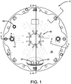
Figs. 1 and2 , it can be seen that the motor brake assembly according to the invention is designated generally by thenumeral 10. Amounting plate 12 is adapted to mount a motor flange (not shown) and is positioned by means of a pilot interface. Anelectromagnetic coil assembly 14 is maintained by ahousing 16, which is secured to themounting plate 12 byappropriate screws 18. Thecoil assembly 14 is comprised of a wound copper coil and electrically-isolating potting. Thecoil housing 16 includes cylindrical pockets 20 containing apply springs 22 that are uniformly circumferentially spaced within thehousing 16. The torque blocks 24, as shown inFig 2 , are secured to the coil housing using threadedfasteners 26 and located by means of appropriate alignment bushings. There are preferably threetorque blocks 24, each rectangular in cross-section and circumferentially spaced 120° apart. Torque blocks have been found to be more stable and occupy a smaller footprint than typical torque pins. - The
brake hub 28 has abore 30 to secure the motor shaft by common industry standards, such as shrink fitting. The brake hub includes anexternal spline 32 that interfaces with multiplefriction plates discs 34. The springs 22 apply axial force to thearmature 36 when the brake is engaged. The friction discs are interposed between separator plates ordiscs 38 andendplate 40.Separator spring assemblies 42, as shown inFig. 3 , are located between thearmature 36 and aseparator disc 38 and between theendplate 40 and theother separator disc 38. This arrangement ensures desired separation of the discs when the safety brake is disengaged, and particularly so when the brake is vertically oriented with gravity urging the disks together. The adjustment shims 44, as shown inFig. 2 , are located between the torque blocks 24 andendplate 40. The torque blocks 24 are clamped to thecoil housing 16 by threadedfasteners 26, which serve to secure the torque blocks 24 during servicing. Pairs of fasteners orbolts 29, shown inFig. 1 , pass through theendplate 40 and associatedtorque block 24 to thecoil housing 16, securing those elements together. Theshims 44 are removed to accommodate wear in the disc stack. - With continued attention to
Fig. 2 , it can be seen that the interleaveddiscs Fig. 7 , the separator discs preferably includeradial slots - A
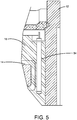
wear indicator pin 46, as shown inFig. 4 , is secured to arelease screw 48 by means of an O-ring 50. Aspring 52 is used to assure the wear indicator pin remains in contact with thearmature 36 during operation. A cartridge-style heater 54, shown inFig. 5 , is mounted to thecoil housing 16. The heater is energized when the brake is set to prevent corrosion caused by moisture contained within the brake assembly. - A
cover 56, as shown inFigs. 1 and2 , is used to protect the brake from the environment. The cover is positioned by means of a pilot interface and is secured to the mountingplate 12 by the use of threadedstuds 58 and encapsulated nuts 60. Thecover 56 also includesprovisions 62 to mount an encoder as may be required for the motor's controller. - As shown in
Figs. 2 and4 , asight glass 64 secured to thecover 56 allows visual access to themechanical wear indicator 46. As is apparent fromFig. 4 , thesight glass 64 is removable to allow access to the release screw, which is provided with a hex head that may be rotated by socket or wrench to manually release the brake by overcoming the springs opposing thearmature 36. As shown, the hex head of therelease screw 48 is notched, having upper and lower top edges, the former being a level for wear assessment when the disc stack is new or refurbished, and latter being for such assessment when theshims 44 have been removed. Asmaller sight glass 66 is also secured to thecover 56 to allow visual access to confirm the presence of adjustment shims 44 interposed between theendplate 40 and torque blocks 24. - With reference to
Fig. 6 , it can be seen that anon-contact proximity switch 68 is installed in thecoil housing 16 and provides a digital indication to an associated control system when the position of thearmature 36 exceeds the axial limit of the design, indicating a need for service or refurbishing. - It will now be appreciated that the
stationary coil housing 16 encompasses and maintains springs 22 that apply pressure or force to thearmature 36 and a stack of a pair ofseparator plates 38 interleaved with threefriction plates 34 and astationary endplate 40. This multi-disc brake stack is released when a DC voltage is applied to thebrake coil 14. The electromagnetic force of thecoil 14 attracts thearmature 36 across an air gap therebetween, thus reducing or overcoming the spring force applied to the brake stack and disengaging the brake. The brake may then be reapplied or actuated when the DC voltage is removed from the brake coil. - The foregoing multi-disc brake is capable of meeting the increasing demand for high-energy motor shaft brakes in a compact and efficient manner. A major drawback of designs for such brakes in the past has been the friction-induced vibration/shaft whirl exhibited during a braking event. The instant invention contemplates mitigating such problem in various ways.
- One such approach is shown in
Fig. 8 wherein a spring-applied friction pad is employed. Here a motor brake assembly, similar to that described above, is represented by the numeral 70. A plurality offriction pads 72 are attached toplungers 74. These plungers are forced bysprings 82 between the torque blocks 76,separator plates 78, andarmature 80, as shown. It will be appreciated that the torque blocks 76 are similar in nature to the torque blocks 24, described above, while the separator plates ordiscs 78 correspond to theseparator discs 38, and thearmature 80 corresponds to thearmature 36, all presented above. - In
Fig. 9 , themotor brake assembly 70 is provided with a fluid-typeaxial damper 84, which is interposed between the fixedendplate 86 andarmature 80 by means of a plunger orpiston rod 88. The axial damper can be of any appropriate type, but is presently contemplated to a be a fluid-filled chamber with a piston head having bores therethrough being movable within the fluid-filled piston chamber, the fluid restricting the movement of the piston head andpiston rod 88 as a function of the viscosity of the fluid and the size of the apertures or holes. - With reference to
Figs. 10 and11 , an apparatus and methodology for achieving the desired damping by the use of springs and bushings is shown. Here themotor brake 70 employs springs 90 introduced axially between theendplate 86 andspring plates 92, which are retained to thetorque block 76 by means ofbolts 94 andbushings 96. Thesprings 90 allow theendplate 86 to move axially along thebushings 96 until bottoming out on thespring plates 92. The detailed structure of the interrelationship of thebolts 94,bushings 96, andtorque lock 76 is best shown inFig. 11 . - With attention now to
Figs. 12 and13 , it can be seen that a friction-dampedlinkage 98 is employed in themotor brake assembly 70 for damping undesired vibrations. Here thelinkage 98 is attached to thecoil housing 16 andarmature 36. The linkage damps the motion of the armature as the brake is released and applied. It achieves this damping by having aspring 106, which applies force to afriction pad 108 that resists the motion between the input andoutput arms bolt assembly 104 interconnects thearms spring 106 andfriction pad 108 interconnected therewith.
Claims (14)
- A multi-disc electric motor brake (10), characterised in that it comprises:a motor mounting plate (12);an electromagnetic coil (14) attached to said mounting plate (12);an armature (36) in operative engagement with said electromagnetic coil (14);a plurality of springs (22) in axially biasing engagement with said armature (36);a hub (28) received on an end of a motor shaft, said hub (28) engaging a plurality of friction rotors (34);a plurality of torque reaction members (24) attached to said mounting plate (12) and in engagement with a plurality of separator stators (38) interleaved with said friction rotors (34) and forming a disc pack;an endplate (40) attached to said torque reaction members (24) and axially encapsulating said disc pack; anda friction-damped linkage (98) interposed between said armature (36) and said mounting plate (12).
- The multi-disc electric motor brake assembly according to claim 1, wherein said torque reaction members (24) are parallel-sided blocks.
- The multi-disc electric motor brake assembly according to claim 1, wherein said friction rotors (34) and separator stators (38) have tapered surfaces matingly engaging each other.
- The multi-disc electric motor brake assembly according to claim 1, wherein said separator stators (38) comprise self-contained, positive-release spring assemblies (42).
- The multi-disc electric motor brake assembly according to claim 1, further comprising disc pack wear adjustment shims (44) interposed between said endplate (40) and said torque reaction members (24).
- The multi-disc electric motor brake assembly according to claim 5, further comprising an externally visible disc pack wear indicator (46).
- The multi-disc electric motor brake assembly according to claim 6, wherein said wear indicator (46) comprises a thread form to manually release the brake by overcoming said springs (22) in axially biasing engagement with said armature (36).
- The multi-disc electric motor brake assembly according to claim 1, wherein said separator stators (38) are radially slotted.
- The multi-disc electric motor brake assembly according to claim 1, further comprising a sealed external enclosure (56) engaging said mounting plate (12).
- The multi-disc electric motor brake assembly according to claim 1, further comprising a spring plate assembly (90, 92) in axial interacting engagement with said endplate (40).
- The multi-disc electric motor brake assembly according to claim 1, further comprising spring-applied friction pads (72) operative to resist motion of said separator stators (38) in relation to said torque reaction members (24).
- The multi-disc electric motor brake assembly according to claim 1, further comprising a shock absorber (84, 90) interposed between said endplate (40) and said armature (36).
- The multi-disc electric motor brake assembly according to claim 1, wherein said friction-damped linkage (98) comprises a pair of arms (100, 102) extending between said armature (36) and mounting plate (12), said arms (100, 102) being secured together with a friction member (108) and spring (106) therebetween.
- A safety brake for offshore marine winch applications, comprising the multi-disc electric motor brake of claim 1.
Applications Claiming Priority (4)
| Application Number | Priority Date | Filing Date | Title |
|---|---|---|---|
| US201562109205P | 2015-01-29 | 2015-01-29 | |
| US201562206964P | 2015-08-19 | 2015-08-19 | |
| PCT/US2016/015271 WO2016123289A1 (en) | 2015-01-29 | 2016-01-28 | Electromagnetic-released, multi-disc enclosed safety brake |
| EP16744076.7A EP3250450B1 (en) | 2015-01-29 | 2016-01-28 | Electromagnetic-released, multi-disc enclosed safety brake |
Related Parent Applications (2)
| Application Number | Title | Priority Date | Filing Date |
|---|---|---|---|
| EP16744076.7A Division EP3250450B1 (en) | 2015-01-29 | 2016-01-28 | Electromagnetic-released, multi-disc enclosed safety brake |
| EP16744076.7A Division-Into EP3250450B1 (en) | 2015-01-29 | 2016-01-28 | Electromagnetic-released, multi-disc enclosed safety brake |
Publications (2)
| Publication Number | Publication Date |
|---|---|
| EP3623274A1 EP3623274A1 (en) | 2020-03-18 |
| EP3623274B1 true EP3623274B1 (en) | 2020-12-23 |
Family
ID=56544307
Family Applications (2)
| Application Number | Title | Priority Date | Filing Date |
|---|---|---|---|
| EP19206132.3A Active EP3623274B1 (en) | 2015-01-29 | 2016-01-28 | Electromagnetic-released, multi-disc enclosed safety brake |
| EP16744076.7A Active EP3250450B1 (en) | 2015-01-29 | 2016-01-28 | Electromagnetic-released, multi-disc enclosed safety brake |
Family Applications After (1)
| Application Number | Title | Priority Date | Filing Date |
|---|---|---|---|
| EP16744076.7A Active EP3250450B1 (en) | 2015-01-29 | 2016-01-28 | Electromagnetic-released, multi-disc enclosed safety brake |
Country Status (6)
| Country | Link |
|---|---|
| US (1) | US10240648B2 (en) |
| EP (2) | EP3623274B1 (en) |
| CN (1) | CN107428397B (en) |
| DK (1) | DK3623274T3 (en) |
| SG (1) | SG11201706137XA (en) |
| WO (1) | WO2016123289A1 (en) |
Families Citing this family (4)
| Publication number | Priority date | Publication date | Assignee | Title |
|---|---|---|---|---|
| JP6617723B2 (en) * | 2017-01-26 | 2019-12-11 | トヨタ自動車株式会社 | Braking device |
| US10584754B2 (en) * | 2017-09-19 | 2020-03-10 | Whippany Actuation Systems Llc | Line replaceable brake |
| CN109114136A (en) * | 2018-10-15 | 2019-01-01 | 宁波新大通电机有限公司 | A kind of double dial electromagnetic brake of threephase asynchronous |
| CN114688190B (en) * | 2022-04-20 | 2023-08-08 | 银川威马电机有限责任公司 | Lightweight electromagnetic power-off brake with strong universality |
Family Cites Families (29)
| Publication number | Priority date | Publication date | Assignee | Title |
|---|---|---|---|---|
| US1660497A (en) * | 1925-06-29 | 1928-02-28 | Bessemer Gas Engine Company | Friction clutch |
| US2025098A (en) * | 1934-12-04 | 1935-12-24 | Dudick Victor | Brake for electric motors |
| US2718292A (en) * | 1952-06-30 | 1955-09-20 | Willard C Meilander | Magnetic clutch |
| US3018852A (en) * | 1958-03-10 | 1962-01-30 | Bendix Corp | Combination retracting mechanism and wear indicator |
| CH520285A (en) * | 1969-03-21 | 1972-03-15 | Baumueller Gmbh A | Single-disc brake arranged on a motor housing for braking the motor shaft, in particular electric motors |
| DE1920128A1 (en) * | 1969-04-21 | 1970-11-05 | Lenze Kg Maschf Hans | Automatic adjustment device for two-disc or multi-disc spring-force clutches or brakes with electromagnetic release of the clutch or ventilation of the brake |
| US4279330A (en) * | 1977-06-27 | 1981-07-21 | Walter Kidde & Company, Inc. | Double-acting disc brake |
| AU550746B2 (en) * | 1980-11-26 | 1986-04-10 | Massey-Ferguson Services N.V. | Disc brake |
| US4445596A (en) * | 1981-09-08 | 1984-05-01 | Facet Enterprises, Inc. | Electromagnetically released spring applied friction brake with torque booster and driving force distributor |
| FR2548303B1 (en) * | 1983-06-30 | 1985-10-25 | Dba | IMPROVEMENTS TO MULTI-DISC BRAKES |
| US4658936A (en) * | 1985-07-25 | 1987-04-21 | Goodyear Aerospace Corporation | Brake temperature and wear indicator |
| AU580453B2 (en) | 1985-11-04 | 1989-01-12 | Johns Perry Industries Pty. Ltd. | Lift sheave |
| US5186287A (en) * | 1990-11-27 | 1993-02-16 | Rexnord Corporation | Simplified motor brake |
| US5228541A (en) * | 1991-12-18 | 1993-07-20 | The Boeing Company | Aircraft brake wear limit indicator having integral configuration control and method |
| US5310025A (en) * | 1992-07-23 | 1994-05-10 | Allied-Signal Inc. | Aircraft brake vibration damper |
| US5528950A (en) * | 1995-03-28 | 1996-06-25 | Eaton Corporation | Transmission inertia brake with ball ramp actuator |
| US5850895A (en) * | 1997-05-12 | 1998-12-22 | Aircraft Braking Systems Corporation | Metallic aircraft brake disk having thermal relief slots |
| DE19733169B4 (en) * | 1997-07-31 | 2005-06-16 | Chr. Mayr Gmbh & Co. Kg | Electromagnetically released friction safety brake with two independent brake circuits |
| US6459182B1 (en) * | 1998-05-14 | 2002-10-01 | Sew-Eurodrive Gmbh | Electric motor with brake |
| AT408394B (en) | 1998-05-29 | 2001-11-26 | Atb Austria Antriebstech Ag | DEVICE FOR BRAKING ELECTRIC MOTORS |
| US6460659B1 (en) * | 2000-12-07 | 2002-10-08 | Caterpillar Inc | Brake wear indicator |
| FR2857348B1 (en) * | 2003-07-08 | 2005-12-02 | Leroy Somer Moteurs | BRAKE SYSTEM WITH SECURED TORQUE RETRIEVAL |
| CN101679009B (en) * | 2007-06-18 | 2014-04-16 | 因温特奥股份公司 | Device and method for controlling a brake device |
| JP4952955B2 (en) * | 2008-12-19 | 2012-06-13 | 株式会社安川電機 | Non-excitation actuated electromagnetic brake and motor equipped with the same |
| JP5341856B2 (en) * | 2010-10-04 | 2013-11-13 | 日立建機株式会社 | Wet brake device |
| CN202659777U (en) * | 2012-07-05 | 2013-01-09 | 成都瑞迪机械实业有限公司 | Manual release type large-torque electromagnetic brake |
| DE102013005239B4 (en) | 2012-11-27 | 2015-03-12 | Sew-Eurodrive Gmbh & Co Kg | Brake assembly and electric motor |
| CN103343789B (en) * | 2013-07-16 | 2015-08-12 | 大连华锐重工集团股份有限公司 | A kind of off-course brake of wind power plant and controlling method thereof |
| US9279468B1 (en) * | 2014-12-09 | 2016-03-08 | Arvinmeritor Technology, Llc | Brake assembly |
-
2016
- 2016-01-28 EP EP19206132.3A patent/EP3623274B1/en active Active
- 2016-01-28 EP EP16744076.7A patent/EP3250450B1/en active Active
- 2016-01-28 DK DK19206132.3T patent/DK3623274T3/en active
- 2016-01-28 SG SG11201706137XA patent/SG11201706137XA/en unknown
- 2016-01-28 WO PCT/US2016/015271 patent/WO2016123289A1/en active Application Filing
- 2016-01-28 US US15/547,194 patent/US10240648B2/en active Active
- 2016-01-28 CN CN201680019626.4A patent/CN107428397B/en active Active
Non-Patent Citations (1)
| Title |
|---|
| None * |
Also Published As
| Publication number | Publication date |
|---|---|
| CN107428397B (en) | 2019-12-20 |
| EP3250450A1 (en) | 2017-12-06 |
| DK3623274T3 (en) | 2021-01-18 |
| CN107428397A (en) | 2017-12-01 |
| SG11201706137XA (en) | 2017-09-28 |
| WO2016123289A1 (en) | 2016-08-04 |
| US10240648B2 (en) | 2019-03-26 |
| EP3250450A4 (en) | 2018-11-14 |
| EP3623274A1 (en) | 2020-03-18 |
| EP3250450B1 (en) | 2020-01-08 |
| US20180023641A1 (en) | 2018-01-25 |
Similar Documents
| Publication | Publication Date | Title |
|---|---|---|
| EP3623274B1 (en) | Electromagnetic-released, multi-disc enclosed safety brake | |
| US5669469A (en) | Integrated elevator drive machine and brake assembly | |
| EP0890037B1 (en) | Multi-disc brake actuator for vibration damping | |
| RU2523365C2 (en) | Torque transfer device | |
| US20070107998A1 (en) | Coupling/brake combination | |
| US3357519A (en) | Aircraft brake damper mechanism | |
| JP2020529559A (en) | Brake system for mining trucks | |
| US4821847A (en) | Liquid cooled brake unit | |
| KR101659513B1 (en) | Electric machine with dampening means | |
| EP2126398B1 (en) | Braking | |
| US2850124A (en) | Brake with resilient friction disc | |
| US8020673B2 (en) | Braking system for high speed and power rotating machinery | |
| US5679993A (en) | Brake assembly for a motor | |
| CN205099138U (en) | Speed limit protection device | |
| EP2061976B1 (en) | Electromagnetic brake for handling system | |
| CA2472036A1 (en) | Elevator brake | |
| CA1038308A (en) | Fail-safe disc brake | |
| EP4332404A1 (en) | Brake device | |
| JPH08259188A (en) | Winding device with brake acting to both sides of clutch | |
| CN201437830U (en) | Automatic spacing tracking electromagnetic brake | |
| EP4321768A1 (en) | Tapered torque plate barrel for improving dynamic stability | |
| CN219345341U (en) | Motor friction plate for braking | |
| SU1504403A1 (en) | Electromagnetic disk brake | |
| SE439050B (en) | ELECTROMAGNETIC DISC BRAKE WITH MANUAL AIR GAP ADJUSTMENT | |
| JPS59739B2 (en) | Friction type electromagnetic coupling device |
Legal Events
| Date | Code | Title | Description |
|---|---|---|---|
| PUAI | Public reference made under article 153(3) epc to a published international application that has entered the european phase |
Free format text: ORIGINAL CODE: 0009012 |
|
| STAA | Information on the status of an ep patent application or granted ep patent |
Free format text: STATUS: THE APPLICATION HAS BEEN PUBLISHED |
|
| AC | Divisional application: reference to earlier application |
Ref document number: 3250450 Country of ref document: EP Kind code of ref document: P |
|
| AK | Designated contracting states |
Kind code of ref document: A1 Designated state(s): AL AT BE BG CH CY CZ DE DK EE ES FI FR GB GR HR HU IE IS IT LI LT LU LV MC MK MT NL NO PL PT RO RS SE SI SK SM TR |
|
| STAA | Information on the status of an ep patent application or granted ep patent |
Free format text: STATUS: REQUEST FOR EXAMINATION WAS MADE |
|
| 17P | Request for examination filed |
Effective date: 20200323 |
|
| RBV | Designated contracting states (corrected) |
Designated state(s): AL AT BE BG CH CY CZ DE DK EE ES FI FR GB GR HR HU IE IS IT LI LT LU LV MC MK MT NL NO PL PT RO RS SE SI SK SM TR |
|
| RIN1 | Information on inventor provided before grant (corrected) |
Inventor name: CLAPP, TIMOTHY A. Inventor name: COLE, RICHARD, E., JR. |
|
| REG | Reference to a national code |
Ref country code: DE Ref legal event code: R079 Ref document number: 602016050459 Country of ref document: DE Free format text: PREVIOUS MAIN CLASS: B63B0021000000 Ipc: B63B0021160000 |
|
| RIC1 | Information provided on ipc code assigned before grant |
Ipc: B66D 5/30 20060101ALI20200623BHEP Ipc: F16D 55/36 20060101ALI20200623BHEP Ipc: B63B 21/16 20060101AFI20200623BHEP Ipc: B66D 5/14 20060101ALI20200623BHEP |
|
| GRAP | Despatch of communication of intention to grant a patent |
Free format text: ORIGINAL CODE: EPIDOSNIGR1 |
|
| STAA | Information on the status of an ep patent application or granted ep patent |
Free format text: STATUS: GRANT OF PATENT IS INTENDED |
|
| INTG | Intention to grant announced |
Effective date: 20200904 |
|
| GRAS | Grant fee paid |
Free format text: ORIGINAL CODE: EPIDOSNIGR3 |
|
| GRAA | (expected) grant |
Free format text: ORIGINAL CODE: 0009210 |
|
| STAA | Information on the status of an ep patent application or granted ep patent |
Free format text: STATUS: THE PATENT HAS BEEN GRANTED |
|
| AC | Divisional application: reference to earlier application |
Ref document number: 3250450 Country of ref document: EP Kind code of ref document: P |
|
| AK | Designated contracting states |
Kind code of ref document: B1 Designated state(s): AL AT BE BG CH CY CZ DE DK EE ES FI FR GB GR HR HU IE IS IT LI LT LU LV MC MK MT NL NO PL PT RO RS SE SI SK SM TR |
|
| REG | Reference to a national code |
Ref country code: GB Ref legal event code: FG4D |
|
| REG | Reference to a national code |
Ref country code: DE Ref legal event code: R096 Ref document number: 602016050459 Country of ref document: DE |
|
| REG | Reference to a national code |
Ref country code: AT Ref legal event code: REF Ref document number: 1347454 Country of ref document: AT Kind code of ref document: T Effective date: 20210115 |
|
| REG | Reference to a national code |
Ref country code: DK Ref legal event code: T3 Effective date: 20210113 |
|
| REG | Reference to a national code |
Ref country code: IE Ref legal event code: FG4D |
|
| REG | Reference to a national code |
Ref country code: NL Ref legal event code: FP |
|
| PG25 | Lapsed in a contracting state [announced via postgrant information from national office to epo] |
Ref country code: GR Free format text: LAPSE BECAUSE OF FAILURE TO SUBMIT A TRANSLATION OF THE DESCRIPTION OR TO PAY THE FEE WITHIN THE PRESCRIBED TIME-LIMIT Effective date: 20210324 Ref country code: NO Free format text: LAPSE BECAUSE OF FAILURE TO SUBMIT A TRANSLATION OF THE DESCRIPTION OR TO PAY THE FEE WITHIN THE PRESCRIBED TIME-LIMIT Effective date: 20210323 Ref country code: FI Free format text: LAPSE BECAUSE OF FAILURE TO SUBMIT A TRANSLATION OF THE DESCRIPTION OR TO PAY THE FEE WITHIN THE PRESCRIBED TIME-LIMIT Effective date: 20201223 Ref country code: RS Free format text: LAPSE BECAUSE OF FAILURE TO SUBMIT A TRANSLATION OF THE DESCRIPTION OR TO PAY THE FEE WITHIN THE PRESCRIBED TIME-LIMIT Effective date: 20201223 |
|
| REG | Reference to a national code |
Ref country code: AT Ref legal event code: MK05 Ref document number: 1347454 Country of ref document: AT Kind code of ref document: T Effective date: 20201223 |
|
| PG25 | Lapsed in a contracting state [announced via postgrant information from national office to epo] |
Ref country code: LV Free format text: LAPSE BECAUSE OF FAILURE TO SUBMIT A TRANSLATION OF THE DESCRIPTION OR TO PAY THE FEE WITHIN THE PRESCRIBED TIME-LIMIT Effective date: 20201223 Ref country code: SE Free format text: LAPSE BECAUSE OF FAILURE TO SUBMIT A TRANSLATION OF THE DESCRIPTION OR TO PAY THE FEE WITHIN THE PRESCRIBED TIME-LIMIT Effective date: 20201223 Ref country code: BG Free format text: LAPSE BECAUSE OF FAILURE TO SUBMIT A TRANSLATION OF THE DESCRIPTION OR TO PAY THE FEE WITHIN THE PRESCRIBED TIME-LIMIT Effective date: 20210323 |
|
| PG25 | Lapsed in a contracting state [announced via postgrant information from national office to epo] |
Ref country code: HR Free format text: LAPSE BECAUSE OF FAILURE TO SUBMIT A TRANSLATION OF THE DESCRIPTION OR TO PAY THE FEE WITHIN THE PRESCRIBED TIME-LIMIT Effective date: 20201223 |
|
| REG | Reference to a national code |
Ref country code: LT Ref legal event code: MG9D |
|
| PG25 | Lapsed in a contracting state [announced via postgrant information from national office to epo] |
Ref country code: PT Free format text: LAPSE BECAUSE OF FAILURE TO SUBMIT A TRANSLATION OF THE DESCRIPTION OR TO PAY THE FEE WITHIN THE PRESCRIBED TIME-LIMIT Effective date: 20210423 Ref country code: RO Free format text: LAPSE BECAUSE OF FAILURE TO SUBMIT A TRANSLATION OF THE DESCRIPTION OR TO PAY THE FEE WITHIN THE PRESCRIBED TIME-LIMIT Effective date: 20201223 Ref country code: LT Free format text: LAPSE BECAUSE OF FAILURE TO SUBMIT A TRANSLATION OF THE DESCRIPTION OR TO PAY THE FEE WITHIN THE PRESCRIBED TIME-LIMIT Effective date: 20201223 Ref country code: SK Free format text: LAPSE BECAUSE OF FAILURE TO SUBMIT A TRANSLATION OF THE DESCRIPTION OR TO PAY THE FEE WITHIN THE PRESCRIBED TIME-LIMIT Effective date: 20201223 Ref country code: SM Free format text: LAPSE BECAUSE OF FAILURE TO SUBMIT A TRANSLATION OF THE DESCRIPTION OR TO PAY THE FEE WITHIN THE PRESCRIBED TIME-LIMIT Effective date: 20201223 Ref country code: EE Free format text: LAPSE BECAUSE OF FAILURE TO SUBMIT A TRANSLATION OF THE DESCRIPTION OR TO PAY THE FEE WITHIN THE PRESCRIBED TIME-LIMIT Effective date: 20201223 Ref country code: CZ Free format text: LAPSE BECAUSE OF FAILURE TO SUBMIT A TRANSLATION OF THE DESCRIPTION OR TO PAY THE FEE WITHIN THE PRESCRIBED TIME-LIMIT Effective date: 20201223 |
|
| PG25 | Lapsed in a contracting state [announced via postgrant information from national office to epo] |
Ref country code: AT Free format text: LAPSE BECAUSE OF FAILURE TO SUBMIT A TRANSLATION OF THE DESCRIPTION OR TO PAY THE FEE WITHIN THE PRESCRIBED TIME-LIMIT Effective date: 20201223 Ref country code: PL Free format text: LAPSE BECAUSE OF FAILURE TO SUBMIT A TRANSLATION OF THE DESCRIPTION OR TO PAY THE FEE WITHIN THE PRESCRIBED TIME-LIMIT Effective date: 20201223 |
|
| REG | Reference to a national code |
Ref country code: CH Ref legal event code: PL |
|
| REG | Reference to a national code |
Ref country code: DE Ref legal event code: R097 Ref document number: 602016050459 Country of ref document: DE |
|
| PG25 | Lapsed in a contracting state [announced via postgrant information from national office to epo] |
Ref country code: MC Free format text: LAPSE BECAUSE OF FAILURE TO SUBMIT A TRANSLATION OF THE DESCRIPTION OR TO PAY THE FEE WITHIN THE PRESCRIBED TIME-LIMIT Effective date: 20201223 Ref country code: IS Free format text: LAPSE BECAUSE OF FAILURE TO SUBMIT A TRANSLATION OF THE DESCRIPTION OR TO PAY THE FEE WITHIN THE PRESCRIBED TIME-LIMIT Effective date: 20210423 Ref country code: LU Free format text: LAPSE BECAUSE OF NON-PAYMENT OF DUE FEES Effective date: 20210128 |
|
| REG | Reference to a national code |
Ref country code: BE Ref legal event code: MM Effective date: 20210131 |
|
| PG25 | Lapsed in a contracting state [announced via postgrant information from national office to epo] |
Ref country code: AL Free format text: LAPSE BECAUSE OF FAILURE TO SUBMIT A TRANSLATION OF THE DESCRIPTION OR TO PAY THE FEE WITHIN THE PRESCRIBED TIME-LIMIT Effective date: 20201223 |
|
| PLBE | No opposition filed within time limit |
Free format text: ORIGINAL CODE: 0009261 |
|
| STAA | Information on the status of an ep patent application or granted ep patent |
Free format text: STATUS: NO OPPOSITION FILED WITHIN TIME LIMIT |
|
| PG25 | Lapsed in a contracting state [announced via postgrant information from national office to epo] |
Ref country code: LI Free format text: LAPSE BECAUSE OF NON-PAYMENT OF DUE FEES Effective date: 20210131 Ref country code: CH Free format text: LAPSE BECAUSE OF NON-PAYMENT OF DUE FEES Effective date: 20210131 |
|
| 26N | No opposition filed |
Effective date: 20210924 |
|
| PG25 | Lapsed in a contracting state [announced via postgrant information from national office to epo] |
Ref country code: ES Free format text: LAPSE BECAUSE OF FAILURE TO SUBMIT A TRANSLATION OF THE DESCRIPTION OR TO PAY THE FEE WITHIN THE PRESCRIBED TIME-LIMIT Effective date: 20201223 |
|
| PG25 | Lapsed in a contracting state [announced via postgrant information from national office to epo] |
Ref country code: SI Free format text: LAPSE BECAUSE OF FAILURE TO SUBMIT A TRANSLATION OF THE DESCRIPTION OR TO PAY THE FEE WITHIN THE PRESCRIBED TIME-LIMIT Effective date: 20201223 |
|
| PG25 | Lapsed in a contracting state [announced via postgrant information from national office to epo] |
Ref country code: BE Free format text: LAPSE BECAUSE OF NON-PAYMENT OF DUE FEES Effective date: 20210131 |
|
| PGFP | Annual fee paid to national office [announced via postgrant information from national office to epo] |
Ref country code: DK Payment date: 20230123 Year of fee payment: 8 Ref country code: IE Payment date: 20230119 Year of fee payment: 8 Ref country code: FR Payment date: 20230124 Year of fee payment: 8 |
|
| PGFP | Annual fee paid to national office [announced via postgrant information from national office to epo] |
Ref country code: IT Payment date: 20230120 Year of fee payment: 8 Ref country code: GB Payment date: 20230119 Year of fee payment: 8 Ref country code: DE Payment date: 20230123 Year of fee payment: 8 |
|
| PG25 | Lapsed in a contracting state [announced via postgrant information from national office to epo] |
Ref country code: CY Free format text: LAPSE BECAUSE OF FAILURE TO SUBMIT A TRANSLATION OF THE DESCRIPTION OR TO PAY THE FEE WITHIN THE PRESCRIBED TIME-LIMIT Effective date: 20201223 |
|
| PGFP | Annual fee paid to national office [announced via postgrant information from national office to epo] |
Ref country code: NL Payment date: 20230119 Year of fee payment: 8 |
|
| P01 | Opt-out of the competence of the unified patent court (upc) registered |
Effective date: 20230613 |
|
| PG25 | Lapsed in a contracting state [announced via postgrant information from national office to epo] |
Ref country code: HU Free format text: LAPSE BECAUSE OF FAILURE TO SUBMIT A TRANSLATION OF THE DESCRIPTION OR TO PAY THE FEE WITHIN THE PRESCRIBED TIME-LIMIT; INVALID AB INITIO Effective date: 20160128 |
|
| PGFP | Annual fee paid to national office [announced via postgrant information from national office to epo] |
Ref country code: NL Payment date: 20240119 Year of fee payment: 9 |
|
| PGFP | Annual fee paid to national office [announced via postgrant information from national office to epo] |
Ref country code: IE Payment date: 20240119 Year of fee payment: 9 |