EP3623187B1 - Multi-directional smooth damper - Google Patents
Multi-directional smooth damper Download PDFInfo
- Publication number
- EP3623187B1 EP3623187B1 EP17909193.9A EP17909193A EP3623187B1 EP 3623187 B1 EP3623187 B1 EP 3623187B1 EP 17909193 A EP17909193 A EP 17909193A EP 3623187 B1 EP3623187 B1 EP 3623187B1
- Authority
- EP
- European Patent Office
- Prior art keywords
- base
- inner cavity
- rotating portion
- disposed
- housing
- Prior art date
- Legal status (The legal status is an assumption and is not a legal conclusion. Google has not performed a legal analysis and makes no representation as to the accuracy of the status listed.)
- Active
Links
Images



Classifications
-
- B—PERFORMING OPERATIONS; TRANSPORTING
- B60—VEHICLES IN GENERAL
- B60H—ARRANGEMENTS OF HEATING, COOLING, VENTILATING OR OTHER AIR-TREATING DEVICES SPECIALLY ADAPTED FOR PASSENGER OR GOODS SPACES OF VEHICLES
- B60H1/00—Heating, cooling or ventilating devices
- B60H1/34—Nozzles; Air-diffusers
- B60H1/3414—Nozzles; Air-diffusers with means for adjusting the air stream direction
- B60H1/3435—Nozzles; Air-diffusers with means for adjusting the air stream direction using only a pivoting frame
- B60H1/3442—Nozzles; Air-diffusers with means for adjusting the air stream direction using only a pivoting frame the frame being spherical
-
- B—PERFORMING OPERATIONS; TRANSPORTING
- B60—VEHICLES IN GENERAL
- B60H—ARRANGEMENTS OF HEATING, COOLING, VENTILATING OR OTHER AIR-TREATING DEVICES SPECIALLY ADAPTED FOR PASSENGER OR GOODS SPACES OF VEHICLES
- B60H1/00—Heating, cooling or ventilating devices
- B60H1/34—Nozzles; Air-diffusers
- B60H1/3414—Nozzles; Air-diffusers with means for adjusting the air stream direction
-
- F—MECHANICAL ENGINEERING; LIGHTING; HEATING; WEAPONS; BLASTING
- F16—ENGINEERING ELEMENTS AND UNITS; GENERAL MEASURES FOR PRODUCING AND MAINTAINING EFFECTIVE FUNCTIONING OF MACHINES OR INSTALLATIONS; THERMAL INSULATION IN GENERAL
- F16D—COUPLINGS FOR TRANSMITTING ROTATION; CLUTCHES; BRAKES
- F16D3/00—Yielding couplings, i.e. with means permitting movement between the connected parts during the drive
- F16D3/16—Universal joints in which flexibility is produced by means of pivots or sliding or rolling connecting parts
- F16D3/26—Hooke's joints or other joints with an equivalent intermediate member to which each coupling part is pivotally or slidably connected
- F16D3/44—Hooke's joints or other joints with an equivalent intermediate member to which each coupling part is pivotally or slidably connected the intermediate member being connected to the coupling parts by ridges, pins, balls, or the like guided in grooves or between cogs
-
- F—MECHANICAL ENGINEERING; LIGHTING; HEATING; WEAPONS; BLASTING
- F24—HEATING; RANGES; VENTILATING
- F24F—AIR-CONDITIONING; AIR-HUMIDIFICATION; VENTILATION; USE OF AIR CURRENTS FOR SCREENING
- F24F13/00—Details common to, or for air-conditioning, air-humidification, ventilation or use of air currents for screening
- F24F13/08—Air-flow control members, e.g. louvres, grilles, flaps or guide plates
- F24F13/10—Air-flow control members, e.g. louvres, grilles, flaps or guide plates movable, e.g. dampers
- F24F13/14—Air-flow control members, e.g. louvres, grilles, flaps or guide plates movable, e.g. dampers built up of tilting members, e.g. louvre
- F24F13/1426—Air-flow control members, e.g. louvres, grilles, flaps or guide plates movable, e.g. dampers built up of tilting members, e.g. louvre characterised by actuating means
-
- B—PERFORMING OPERATIONS; TRANSPORTING
- B60—VEHICLES IN GENERAL
- B60H—ARRANGEMENTS OF HEATING, COOLING, VENTILATING OR OTHER AIR-TREATING DEVICES SPECIALLY ADAPTED FOR PASSENGER OR GOODS SPACES OF VEHICLES
- B60H1/00—Heating, cooling or ventilating devices
- B60H1/34—Nozzles; Air-diffusers
- B60H2001/3471—Details of actuators
-
- B—PERFORMING OPERATIONS; TRANSPORTING
- B60—VEHICLES IN GENERAL
- B60H—ARRANGEMENTS OF HEATING, COOLING, VENTILATING OR OTHER AIR-TREATING DEVICES SPECIALLY ADAPTED FOR PASSENGER OR GOODS SPACES OF VEHICLES
- B60H1/00—Heating, cooling or ventilating devices
- B60H1/34—Nozzles; Air-diffusers
- B60H2001/3471—Details of actuators
- B60H2001/3478—Details of actuators acting on additional damper doors
-
- F—MECHANICAL ENGINEERING; LIGHTING; HEATING; WEAPONS; BLASTING
- F16—ENGINEERING ELEMENTS AND UNITS; GENERAL MEASURES FOR PRODUCING AND MAINTAINING EFFECTIVE FUNCTIONING OF MACHINES OR INSTALLATIONS; THERMAL INSULATION IN GENERAL
- F16C—SHAFTS; FLEXIBLE SHAFTS; ELEMENTS OR CRANKSHAFT MECHANISMS; ROTARY BODIES OTHER THAN GEARING ELEMENTS; BEARINGS
- F16C33/00—Parts of bearings; Special methods for making bearings or parts thereof
- F16C33/02—Parts of sliding-contact bearings
- F16C33/04—Brasses; Bushes; Linings
- F16C33/06—Sliding surface mainly made of metal
- F16C33/10—Construction relative to lubrication
- F16C33/102—Construction relative to lubrication with grease as lubricant
-
- F—MECHANICAL ENGINEERING; LIGHTING; HEATING; WEAPONS; BLASTING
- F16—ENGINEERING ELEMENTS AND UNITS; GENERAL MEASURES FOR PRODUCING AND MAINTAINING EFFECTIVE FUNCTIONING OF MACHINES OR INSTALLATIONS; THERMAL INSULATION IN GENERAL
- F16D—COUPLINGS FOR TRANSMITTING ROTATION; CLUTCHES; BRAKES
- F16D3/00—Yielding couplings, i.e. with means permitting movement between the connected parts during the drive
- F16D3/16—Universal joints in which flexibility is produced by means of pivots or sliding or rolling connecting parts
- F16D3/20—Universal joints in which flexibility is produced by means of pivots or sliding or rolling connecting parts one coupling part entering a sleeve of the other coupling part and connected thereto by sliding or rolling members
- F16D3/202—Universal joints in which flexibility is produced by means of pivots or sliding or rolling connecting parts one coupling part entering a sleeve of the other coupling part and connected thereto by sliding or rolling members one coupling part having radially projecting pins, e.g. tripod joints
- F16D3/205—Universal joints in which flexibility is produced by means of pivots or sliding or rolling connecting parts one coupling part entering a sleeve of the other coupling part and connected thereto by sliding or rolling members one coupling part having radially projecting pins, e.g. tripod joints the pins extending radially outwardly from the coupling part
- F16D3/2052—Universal joints in which flexibility is produced by means of pivots or sliding or rolling connecting parts one coupling part entering a sleeve of the other coupling part and connected thereto by sliding or rolling members one coupling part having radially projecting pins, e.g. tripod joints the pins extending radially outwardly from the coupling part having two pins
Definitions
- the present invention relates to a multi-directional smooth damper and a circular air conditioner vent comprising said multi-directional smooth damper.
- adjustment of an air conditioner vent includes adjusting an air volume switch and adjusting air direction. Adjusting the air volume switch of a square vent mainly controls a switch of the square vent via an external dial wheel, thereby adjusting the air volume. The air direction of the square vent is adjusted by adjusting a vertical direction of blades and horizontal direction of the blades.
- a circular vent does not have the dial wheel and a vent control structure
- the adjustment of the air volume switch of the circular vent is realized through a closed-vent structure arranged on an external surface of the circular vent. Since the circular vent does not have vertical and horizontal blades, the adjustment of the air direction is realized by an overall rotation of an inner housing. Since the air direction should be maintained via friction between the internal and external housing after adjustment, mostly the internal housing directly contacts the external housing, and operating force depends on adjusting a size of the internal housing and a size of the external housing, and the friction between the plastic internal and the plastic housing external housing brings noise and not smooth operation.
- Another method for adjusting the air direction is to realize the adjustment of the air direction by matching an elastic convex structure with a latch. Although the method is more comfortable, a process for matching the elastic convex structure with the latch brings a "tak tak" sound that makes users feel aversion.
- a common universal ball joint includes a bearing sleeve and a ball head disposed in the bearing sleeve.
- the operating force for blade deflection is controlled by the clamping in the ball head disposed in the bearing sleeve. That is, friction resistance between the bearing sleeve and the ball head is adjusted by corresponding pre-tightening of the bearing sleeve around the ball head. Since wear of used material and the weakening of elasticity is caused by aging, retention force of the universal ball joint decreases over time.
- the retention force of the blade is less and less until the air guide device in the housing no longer has sufficient support to maintain a preset direction for airflow.
- there is a gap is between the bearing sleeve and the ball head, which results in an unexpected noise in the car and changes in the size of the ball head and housing caused by the temperature change, further making operating force not smooth or no operating force.
- the above-mentioned method needs to add the panel rotation button to control the structure of a vent switch and pass the operating force to the vent through wheel gear, thereby, to turn on and off vent. That is, the smooth of operation force depends on high precision size, transmission nodes are too many, and the problem risk is multiplied.
- a common damping device of the air conditioner vent of car which technical requirements for smooth operating force mainly realized by a coordination control of shaft and shaft hole.
- the above technology requires precise size control and is tested repeatedly for different products to meet the requirements.
- This structure is not conducive to form a smooth and constant damping force from the cooperation of the rotating shaft and shaft hole.
- Document DE 10 2009 009241 A1 discloses an air outlet having a housing and in which pivoting flaps are arranged for closing the housing.
- the air outlet comprises a locking device for holding the flaps in a pivoted position.
- the locking device is a non-rotatable friction element made of silicone or a thermoplastic elastomer with a high coefficient of friction.
- a bearing shell of a pivot pin is frictionally held in the friction element.
- Document US 2013/210333 A1 discloses an air vent having a housing and an air guiding means that is swivel-mounted in the housing by means of a ball joint having a bearing shell and a ball head mounted in the bearing shell.
- the ball head comprises a non-rotatable first spherical segments and a second spherical member that is displaced in the direction of a longitudinal axis of the vent, away from the first spherical segment.
- the present invention provides a multi-directional smooth damper and a circular air conditioner vent to overcome the above problems.
- the grease groove is formed from the opening of the one end of the inner cavity of the base along the surface of the inner cavity of the base to extend to the opening of the other end of the inner cavity of the base.
- the first rotating portion comprises a first ball and a first operating shaft; an end of the first operating shaft is connected with the first ball.
- the first ball is rotated and disposed in the inner cavity of the base.
- the first operating shaft passes through the opening of the one end of the base.
- the first ball comprises an opening and an inner cavity.
- the second rotating portion comprises a second ball and a second operating shaft, and an end of the second operating shaft is connected to the second ball.
- the second ball is rotated and disposed in the inner cavity of the first rotating portion, and the second operating shaft passes through the opening of the end of the base away from the first rotating portion.
- annular protrusion is disposed on the second operating shaft; a connecting piece is connected with the annular protrusion and is connected to an external component.
- an ear column is disposed on the second ball of the second rotating portion and the ear column drives the second rotating portion to rotate around axis.
- An ear column avoidance groove is disposed in the inner cavity of the first rotating portion and is matched with the ear column; the first rotating portion drives the second rotating portion to rotate synchronously around the axis via matching the ear column with the ear column avoidance groove.
- the ear column is a columnar projection distributed in the second ball in the non-rotational axis direction.
- the present invention also provides a circular air conditioner vent, where the circular air conditioner vent comprises a housing, a blade disposed in the housing, an air door, and the above described multi-directional smooth damper.
- the base of the multi-directional smooth damper is fixed and connected with an inner surface of the housing; the blade is circular and connected with the first rotating portion of the multi-directional smooth damper.
- the air door is connected with the housing and is rotated by the multi-directional smooth damper.
- the circular air conditioner vent further comprises a connecting rod shaft connected with the second operating shaft of the multi-directional smooth damper and a bevel gear connected with the connecting rod shaft.
- the bevel gear is meshed with a semi-bevel gear disposed on the air door.
- the air door comprises a rotating shaft and two air door bodies disposed on the rotating shaft.
- the two air door bodies are unfolded in a shape corresponding to the opening of the one end of the housing away from the blade.
- the semi-bevel gear is staggered and disposed on position of the rotating shaft corresponding to two air door bodies.
- the present invention uses the multi-directional smooth damper to uniformly adjust an air volume switch and air direction of the circular air conditioner vent, which simplifies structure, saves operating space, and simplifies operation.
- a grease layer is coated between an external surface of the first rotating portion and the inner cavity of the base, which performs lubrication action and keeps constant damper force because of viscosity of the grease.
- the structure is simple, which is convenient to assemble and achieves smooth rotation and keeps stable retention force. When the structure does not change, different grease is coated, the damper force is also different.
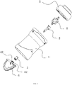
- the present invention provides a multi-directional smooth damper 1, as shown in FIG. 1 to FIG. 5 , includes a base 11, a first rotating portion 12, and a second rotating portion 13.
- the base 11 includes an inner cavity that is spherically -shaped, where two ends of the inner cavity defining openings.
- a first end of the first rotating portion 12 is rotated and disposed in the inner cavity of the base 11 and a shape of the first end of the first rotating portion 12 corresponds to the shape of the inner cavity.
- a second end of the first rotating portion 12 passes through an opening of one end of the base 11.
- the first rotating portion 12 is disposed at one end of the base 11 having the opening and the inner cavity.
- a first end of the second rotating portion 13 is rotated and disposed in an inner cavity of the first rotating portion 12 and a shape of the inner cavity of the first rotating portion 12 corresponds to the shape of the inner cavity.
- a second end of the second rotating portion 13 passes through the one opening of one end of the base 11 away from the first rotating portion 12.
- At least one grease groove is disposed on a surface of the inner cavity of the base 11.
- the grease groove of the embodiment is formed from the opening of one end of the base 11 along the surface of the inner cavity of the base 11 to extend to an opening of the other end of the base 11.
- the grease groove is regarded as a groove circumferentially disposed along the surface of the inner cavity of the base 11.
- the grease groove is used to store grease having a viscosity and capable of generating a constant damping force.
- the first rotating portion 12 rotates relative to the base 11 to bring the grease of the grease groove.
- a grease layer is formed between the surface of the first rotating portion 12 and the surface of the inner cavity of the base 11, and between the surface of the second rotating portion 13 and the surface of the inner cavity of the first rotating portion 12.
- the grease used in the grease layer is a lubricating material and a common damping material, which utilizes its lubricity and viscosity to generate a smooth and constant damping force between the two components moving relative to each other.
- the grease layer forms a thin oil film in the gap between different components.
- the oil film performs lubrication action when the components rotate and match each other, further making the components rotate smoothly.
- the viscosity of the grease can make the components generate the constant friction to form constant damping force when rotating.
- the smooth and constant damping force is formed when the components are relatively rotated and matched using the above structure, and the structure is simple and convenient in assembly.
- the grease layer forms the thin oil film in the gap between the surface of the inner cavity of the base 11 and the surface of the first rotating portion 12.
- the oil film performs lubrication action when the first rotating portion 12 and the base 11 rotate and match each other, further making the first rotating portion 12 rotate smoothly in the base 11.
- the constant friction can be generated to form constant damping force when the first rotating portion 12 rotates smoothly in the base 11 because of the viscosity of the grease.
- the smooth and constant damping force is formed when the first rotating portion 12 and the base 11 are relatively rotated and matched.
- the first rotating portion 12 includes a first ball 121 and a first operating shaft 122, where an end of the first operating shaft 122 is connected with the first ball 121.
- the first ball 121 is rotated and disposed in the inner cavity of the base 11.
- the first operating shaft 122 passes through the opening of the one end of the base 11.
- the second rotating portion 13 includes a second ball 131 and a second operating shaft 132, where an end of the second operating shaft 132 is connected to the second ball 131.
- the second ball 131 is rotated and disposed in the inner cavity of the first rotating portion 12,
- the second operating shaft 132 passes through the opening of the end of the base 11 away from the first rotating portion 12.
- the first operating shaft 122 drives the first ball 121 to rotate in the inner cavity of the base 11.
- An annular protrusion 123 and a first connecting piece 124 are disposed on an end of the first operating shaft 122 away from the base 11, a first connecting piece 124 is connected with the annular protrusion 123 and is connected to the external component.
- An annular protrusion 134 is disposed on an end of the second operating shaft 132 away from the base 11.
- a second connecting piece 135 is connected to the external component and is connected with the annular protrusion 134.
- the first connecting piece 124 and the second connecting piece 135 are buckled to facilitate the assembly and disassembly with other components.
- the base 11 provides an inner cavity that is spherically-shaped, where both ends of the inner cavity defining openings.
- the base 11 includes an end cover 112 having a through hole and sealingly connected with the opening of one end of the base 11.
- the base 11 also includes a base body 111 with a stepped and convex shape.
- a sinking platform is disposed on the end cover 112, and is buckled and connected to a convex plate disposed on one end of the base body 111, where the convex plate is connected with the sinking platform by ultrasonic welding.
- the first operating shaft 122 passes through the hole of the end cover 112.
- a radial width of the through hole on the end cover 112 is greater than radial width of the first operating shaft 122 to make more room for multi-directional movement of the first operating shaft 122.
- an annular seal groove is disposed along an edge of the through hole of the end cover 112, and a sealing ring 113 is disposed in the groove.
- an annular seal groove is formed at a joint position between the annular protrusion 134 of the second rotating portion 13 and the second connecting piece 135, and the sealing ring 113 is disposed in the groove, thereby, sealing the grease is sealed in the base 11 to effectively prevent oil leakage, which makes the damper 1 to maintain the constant damping force.
- a third connecting piece 114 is disposed on an outer surface of the base 11. The third connecting piece 114 of the embodiment is a buckle.
- An ear column 133 is disposed on the second ball 131 of the embodiment.
- the ear column 133 of the embodiment is a columnar protrusion disposed on the surface of the second ball 131.
- An ear column avoidance groove is disposed in the inner cavity of the first ball 121 and is matched with the ear column 133.
- the first rotating portion 12 drives the second rotating portion 13 to rotate synchronously around the axis using the ear column 133.
- the ear column 133 is a columnar projection distributed in the second ball 131 in the non-rotational axis direction.
- the first rotating portion 12 drives the second rotating portion 13 synchronously around the axis by matching the ear column 133 with the ear column avoidance groove.
- a plurality of ear columns 133 respectively disposed on two or more sides in the axial direction.
- the ear column 133 of the embodiment is disposed in the columnar protrusion of the second ball 131 in four directions of the same horizontal plane.
- the embodiment provides a circular air conditioner vent includes a housing 4, a blade 2 disposed in the housing 4, an air door 6, and a multi-directional smooth damper 1 described in the above embodiment 1.
- the base 11 of the multi-directional smooth damper 1 is fixed and connected with an inner surface of the housing 4.
- the blade 2 is circular and rigidly connected with the first operating shaft 122 of the first rotating portion 12 of the multi-directional smooth damper 1.
- the first operating shaft 122 is driven by controlling the direction of blade 2. Thereby, the first rotating portion 12 is controlled to rotate around the axis or around the ball center to make a multi-directional rotational motion.
- the air door 6 is rotatable and is connected with the housing 4 and is rotated by the multi-directional smooth damper 1.
- the air door 6 includes a rotating shaft 63 connected with the housing 4, an air door body 61 which is rotated and connected with the rotating shaft 63, and a semi-bevel gear 62 disposed on the air door body 61.
- the air door body 61 rotates around the rotating shaft 63 to control opening and closing of the air door 6.
- the air door 6 can effectively shade one end of the housing 4 far away from the blade 2. Thereby, the gas is prevented from entering into the housing 4.
- the air volume is adjusted, namely an opening angle of the air door 6 is adjusted. Thereby, control adjustment of the air volume is achieved.
- the circular air conditioner vent of the embodiment includes a connecting rod shaft 3 rigidly connected with the end of the second operating shaft 132 of the multi-directional smooth damper 1 and a bevel gear 5 rigidly connected with an end of the connecting rod shaft 3.
- the bevel gear 5 is meshed with the semi-bevel gear 62 disposed on the air door 6.
- the bevel gear 5 rotated around the axis of the connecting rod shaft 3. Thereby, the air door 6 is driven to rotate around the rotating shaft 63.
- the air door 6 of the embodiment includes the rotating shaft 63 and two air door bodies 61 disposed on the rotating shaft 63.
- the two air door bodies 61 are unfolded in a shape corresponding to the opening of the one end of the housing 4 away from the blade 2.
- the semi-bevel gear 62 is staggered and disposed on position of the rotating shaft 63 corresponding to two air door bodies 61.
- the housing 4 of the embodiment is a cylinder and two ends of the cylinder are open.
- the air door 6 includes two semi-circular air door bodies 61 corresponding to the rotating shaft 63.
- the semi-bevel gear 62 is disposed on each of the air door bodies 61.
- the semi-bevel gears 62 on the two air door bodies 61 are staggered and disposed, and the shape of the two semicircular air door bodies 61 after unfolding is circular corresponding to a circular-shaped of the one end of the housing 4 away from the blade 2.
- the bevel gear 5 on the connecting rod shaft 3 simultaneously meshes with the semi-bevel gear 62 on the two air door bodies 61. Thereby, the two air door bodies 61 are simultaneously driven to rotate around the rotating shaft 63. Since the semi-bevel gears 62 are oppositely disposed, the two air door bodies 61 are rotated in opposite directions by the bevel gear 5.
- the blade 2 When air door is open or closed, or the air volume is adjusted, the blade 2 is controlled to rotate around the axis. Thereby, the first rotating portion 12 is driven to rotate around the axis corresponding to the base 11. Furthermore, the second rotating portion 13 is driven to rotate around the axis via matching the ear column 133 with the ear column avoidance groove.
- the bevel gear 5 rotates around the axis via the connecting rod shaft 3 connected with the second rotating portion 13, and the bevel gear 5 is meshed with the semi-bevel gear 62 on the air door 6, thereby realizing that the rotating shaft 63 on the vent body 61 rotates, the opening or closing of the air door 6, or adjusting of the air volume of the air door 6 are realized.
Landscapes
- Engineering & Computer Science (AREA)
- Mechanical Engineering (AREA)
- Physics & Mathematics (AREA)
- Thermal Sciences (AREA)
- General Engineering & Computer Science (AREA)
- Chemical & Material Sciences (AREA)
- Combustion & Propulsion (AREA)
- Air-Flow Control Members (AREA)
- Air-Conditioning For Vehicles (AREA)
Description
- The present invention relates to a multi-directional smooth damper and a circular air conditioner vent comprising said multi-directional smooth damper.
- In an automobile air conditioner field, adjustment of an air conditioner vent includes adjusting an air volume switch and adjusting air direction. Adjusting the air volume switch of a square vent mainly controls a switch of the square vent via an external dial wheel, thereby adjusting the air volume. The air direction of the square vent is adjusted by adjusting a vertical direction of blades and horizontal direction of the blades.
- However, a circular vent does not have the dial wheel and a vent control structure, the adjustment of the air volume switch of the circular vent is realized through a closed-vent structure arranged on an external surface of the circular vent. Since the circular vent does not have vertical and horizontal blades, the adjustment of the air direction is realized by an overall rotation of an inner housing. Since the air direction should be maintained via friction between the internal and external housing after adjustment, mostly the internal housing directly contacts the external housing, and operating force depends on adjusting a size of the internal housing and a size of the external housing, and the friction between the plastic internal and the plastic housing external housing brings noise and not smooth operation.
- Another method for adjusting the air direction is to realize the adjustment of the air direction by matching an elastic convex structure with a latch. Although the method is more comfortable, a process for matching the elastic convex structure with the latch brings a "tak tak" sound that makes users feel aversion.
- Furthermore, for the circuit vent in the market, in order to integrate the air direction adjustment and the adjustment of the air volume switch in one, the circular vent on the prior art mainly through the universal ball joint and is realized by adding a panel rotation button. A common universal ball joint includes a bearing sleeve and a ball head disposed in the bearing sleeve. In this universal ball joint, the operating force for blade deflection is controlled by the clamping in the ball head disposed in the bearing sleeve. That is, friction resistance between the bearing sleeve and the ball head is adjusted by corresponding pre-tightening of the bearing sleeve around the ball head. Since wear of used material and the weakening of elasticity is caused by aging, retention force of the universal ball joint decreases over time. Namely the retention force of the blade is less and less until the air guide device in the housing no longer has sufficient support to maintain a preset direction for airflow. In an extreme case, there is a gap is between the bearing sleeve and the ball head, which results in an unexpected noise in the car and changes in the size of the ball head and housing caused by the temperature change, further making operating force not smooth or no operating force.
- The above-mentioned method needs to add the panel rotation button to control the structure of a vent switch and pass the operating force to the vent through wheel gear, thereby, to turn on and off vent. That is, the smooth of operation force depends on high precision size, transmission nodes are too many, and the problem risk is multiplied.
- At present, a common damping device of the air conditioner vent of car which technical requirements for smooth operating force mainly realized by a coordination control of shaft and shaft hole. The above technology requires precise size control and is tested repeatedly for different products to meet the requirements. This structure is not conducive to form a smooth and constant damping force from the cooperation of the rotating shaft and shaft hole. Most circular vent for integrating of the air direction adjustment and the adjustment of the air volume switch in one, the structure is complex, the installation is very inconvenient, the operation cannot be smooth.
- Document
DE 10 2009 009241 A1 discloses an air outlet having a housing and in which pivoting flaps are arranged for closing the housing. The air outlet comprises a locking device for holding the flaps in a pivoted position. The locking device is a non-rotatable friction element made of silicone or a thermoplastic elastomer with a high coefficient of friction. A bearing shell of a pivot pin is frictionally held in the friction element. - Document
US 2013/210333 A1 discloses an air vent having a housing and an air guiding means that is swivel-mounted in the housing by means of a ball joint having a bearing shell and a ball head mounted in the bearing shell. The ball head comprises a non-rotatable first spherical segments and a second spherical member that is displaced in the direction of a longitudinal axis of the vent, away from the first spherical segment. - Thereby, it is necessary to develop a novel multi-directional smooth damper and a circular air conditioner vent comprising said multi-directional smooth damper with a simple structure, smooth operation, and stable damping force to overcome existing problems in the prior art.
- In view of the above problems mentioned in the prior art, the present invention provides a multi-directional smooth damper and a circular air conditioner vent to overcome the above problems.
- In accordance with the present invention there is provided a multi-directional smooth damper as set out in
independent claim 1. Preferred embodiments of the present invention are laid down in the appended dependent claims. - Preferably, the grease groove is formed from the opening of the one end of the inner cavity of the base along the surface of the inner cavity of the base to extend to the opening of the other end of the inner cavity of the base.
- Preferably, the first rotating portion comprises a first ball and a first operating shaft; an end of the first operating shaft is connected with the first ball. The first ball is rotated and disposed in the inner cavity of the base. The first operating shaft passes through the opening of the one end of the base. The first ball comprises an opening and an inner cavity. The second rotating portion comprises a second ball and a second operating shaft, and an end of the second operating shaft is connected to the second ball. The second ball is rotated and disposed in the inner cavity of the first rotating portion, and the second operating shaft passes through the opening of the end of the base away from the first rotating portion.
- Preferably, an annular protrusion is disposed on the second operating shaft; a connecting piece is connected with the annular protrusion and is connected to an external component.
- Preferably, an ear column is disposed on the second ball of the second rotating portion and the ear column drives the second rotating portion to rotate around axis. An ear column avoidance groove is disposed in the inner cavity of the first rotating portion and is matched with the ear column; the first rotating portion drives the second rotating portion to rotate synchronously around the axis via matching the ear column with the ear column avoidance groove.
- Preferably, the ear column is a columnar projection distributed in the second ball in the non-rotational axis direction.
- The present invention also provides a circular air conditioner vent, where the circular air conditioner vent comprises a housing, a blade disposed in the housing, an air door, and the above described multi-directional smooth damper. The base of the multi-directional smooth damper is fixed and connected with an inner surface of the housing; the blade is circular and connected with the first rotating portion of the multi-directional smooth damper. The air door is connected with the housing and is rotated by the multi-directional smooth damper.
- Preferably, the circular air conditioner vent further comprises a connecting rod shaft connected with the second operating shaft of the multi-directional smooth damper and a bevel gear connected with the connecting rod shaft. The bevel gear is meshed with a semi-bevel gear disposed on the air door.
- Preferably, the air door comprises a rotating shaft and two air door bodies disposed on the rotating shaft. The two air door bodies are unfolded in a shape corresponding to the opening of the one end of the housing away from the blade. The semi-bevel gear is staggered and disposed on position of the rotating shaft corresponding to two air door bodies.
- From the above technical scheme, the present invention uses the multi-directional smooth damper to uniformly adjust an air volume switch and air direction of the circular air conditioner vent, which simplifies structure, saves operating space, and simplifies operation. When the first rotating portion rotates in the inner cavity of the base, a grease layer is coated between an external surface of the first rotating portion and the inner cavity of the base, which performs lubrication action and keeps constant damper force because of viscosity of the grease. The structure is simple, which is convenient to assemble and achieves smooth rotation and keeps stable retention force. When the structure does not change, different grease is coated, the damper force is also different.
- The drawings are included to provide a further understanding of embodiments of the present invention, which form portions of the specification and are used to illustrate implementation manners of the present invention and are intended to illustrate operating principles of the present invention together with the description. Apparently, the drawings in the following description are merely some of the embodiments of the present invention.
-
FIG. 1 is a structural schematic diagram and exploded schematic diagram of a multi-directional smooth damper of the present invention; -
FIG. 2 is an exploded schematic diagram of a circular air conditioner vent of the present invention; -
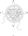
FIG. 3 is a front structural schematic diagram when using the circular air conditioner vent of the present invention. -
FIG. 4 is a sectional diagram showing A-A direction of the circular air conditioner vent of the present invention. -
FIG. 5 is a sectional diagram showing B-B direction of the circular air conditioner vent of the present invention. - A technical proposal in the embodiments of the present invention is clearly and completely described in the following with reference to the drawings and embodiments. Obviously, the described embodiments are only a part of the embodiments of the present invention.
- The present invention provides a multi-directional
smooth damper 1, as shown inFIG. 1 to FIG. 5 , includes abase 11, a first rotatingportion 12, and a secondrotating portion 13. Thebase 11 includes an inner cavity that is spherically -shaped, where two ends of the inner cavity defining openings. A first end of the first rotatingportion 12 is rotated and disposed in the inner cavity of thebase 11 and a shape of the first end of the first rotatingportion 12 corresponds to the shape of the inner cavity. A second end of the first rotatingportion 12 passes through an opening of one end of thebase 11. The firstrotating portion 12 is disposed at one end of the base 11 having the opening and the inner cavity. A first end of the second rotatingportion 13 is rotated and disposed in an inner cavity of the first rotatingportion 12 and a shape of the inner cavity of the first rotatingportion 12 corresponds to the shape of the inner cavity. A second end of the second rotatingportion 13 passes through the one opening of one end of the base 11 away from the first rotatingportion 12. - At least one grease groove is disposed on a surface of the inner cavity of the
base 11. The grease groove of the embodiment is formed from the opening of one end of thebase 11 along the surface of the inner cavity of the base 11 to extend to an opening of the other end of thebase 11. In another embodiment, the grease groove is regarded as a groove circumferentially disposed along the surface of the inner cavity of thebase 11. The grease groove is used to store grease having a viscosity and capable of generating a constant damping force. The firstrotating portion 12 rotates relative to the base 11 to bring the grease of the grease groove. Thereby, a grease layer is formed between the surface of the first rotatingportion 12 and the surface of the inner cavity of thebase 11, and between the surface of the second rotatingportion 13 and the surface of the inner cavity of the first rotatingportion 12. The grease used in the grease layer is a lubricating material and a common damping material, which utilizes its lubricity and viscosity to generate a smooth and constant damping force between the two components moving relative to each other. When different components relatively rotate, the grease layer forms a thin oil film in the gap between different components. The oil film performs lubrication action when the components rotate and match each other, further making the components rotate smoothly. And the viscosity of the grease can make the components generate the constant friction to form constant damping force when rotating. The smooth and constant damping force is formed when the components are relatively rotated and matched using the above structure, and the structure is simple and convenient in assembly. Especially for the relative rotation of the first rotatingportion 12 in thebase 11, the grease layer forms the thin oil film in the gap between the surface of the inner cavity of thebase 11 and the surface of the first rotatingportion 12. The oil film performs lubrication action when the first rotatingportion 12 and the base 11 rotate and match each other, further making the first rotatingportion 12 rotate smoothly in thebase 11. The constant friction can be generated to form constant damping force when the first rotatingportion 12 rotates smoothly in thebase 11 because of the viscosity of the grease. The smooth and constant damping force is formed when the first rotatingportion 12 and the base 11 are relatively rotated and matched. - To be specific, the first rotating
portion 12 includes afirst ball 121 and afirst operating shaft 122, where an end of thefirst operating shaft 122 is connected with thefirst ball 121. Thefirst ball 121 is rotated and disposed in the inner cavity of thebase 11. Thefirst operating shaft 122 passes through the opening of the one end of thebase 11. The secondrotating portion 13 includes asecond ball 131 and asecond operating shaft 132, where an end of thesecond operating shaft 132 is connected to thesecond ball 131. Thesecond ball 131 is rotated and disposed in the inner cavity of the first rotatingportion 12, Thesecond operating shaft 132 passes through the opening of the end of the base 11 away from the first rotatingportion 12. Thefirst operating shaft 122 drives thefirst ball 121 to rotate in the inner cavity of thebase 11. Anannular protrusion 123 and a first connectingpiece 124 are disposed on an end of thefirst operating shaft 122 away from thebase 11, a first connectingpiece 124 is connected with theannular protrusion 123 and is connected to the external component. Anannular protrusion 134 is disposed on an end of thesecond operating shaft 132 away from thebase 11. A second connectingpiece 135 is connected to the external component and is connected with theannular protrusion 134. In the embodiment, the first connectingpiece 124 and the second connectingpiece 135 are buckled to facilitate the assembly and disassembly with other components. - The
base 11 provides an inner cavity that is spherically-shaped, where both ends of the inner cavity defining openings. Specifically, thebase 11 includes anend cover 112 having a through hole and sealingly connected with the opening of one end of thebase 11. The base 11 also includes abase body 111 with a stepped and convex shape. A sinking platform is disposed on theend cover 112, and is buckled and connected to a convex plate disposed on one end of thebase body 111, where the convex plate is connected with the sinking platform by ultrasonic welding. Thefirst operating shaft 122 passes through the hole of theend cover 112. It should be noted that a radial width of the through hole on theend cover 112 is greater than radial width of thefirst operating shaft 122 to make more room for multi-directional movement of thefirst operating shaft 122. In order to prevent overflow of the grease, and an annular seal groove is disposed along an edge of the through hole of theend cover 112, and asealing ring 113 is disposed in the groove. In order to obtain better sealing, the one opening of the one end of thebase 11, an annular seal groove is formed at a joint position between theannular protrusion 134 of the second rotatingportion 13 and the second connectingpiece 135, and thesealing ring 113 is disposed in the groove, thereby, sealing the grease is sealed in the base 11 to effectively prevent oil leakage, which makes thedamper 1 to maintain the constant damping force. A third connectingpiece 114 is disposed on an outer surface of thebase 11. The third connectingpiece 114 of the embodiment is a buckle. - An
ear column 133 is disposed on thesecond ball 131 of the embodiment. Theear column 133 of the embodiment is a columnar protrusion disposed on the surface of thesecond ball 131. An ear column avoidance groove is disposed in the inner cavity of thefirst ball 121 and is matched with theear column 133. The firstrotating portion 12 drives the second rotatingportion 13 to rotate synchronously around the axis using theear column 133. Theear column 133 is a columnar projection distributed in thesecond ball 131 in the non-rotational axis direction. The firstrotating portion 12 drives the second rotatingportion 13 synchronously around the axis by matching theear column 133 with the ear column avoidance groove. In order to achieve a better effect, a plurality ofear columns 133 respectively disposed on two or more sides in the axial direction. Theear column 133 of the embodiment is disposed in the columnar protrusion of thesecond ball 131 in four directions of the same horizontal plane. - The embodiment provides a circular air conditioner vent includes a
housing 4, ablade 2 disposed in thehousing 4, anair door 6, and a multi-directionalsmooth damper 1 described in theabove embodiment 1. Thebase 11 of the multi-directionalsmooth damper 1 is fixed and connected with an inner surface of thehousing 4. Theblade 2 is circular and rigidly connected with thefirst operating shaft 122 of the first rotatingportion 12 of the multi-directionalsmooth damper 1. Thefirst operating shaft 122 is driven by controlling the direction ofblade 2. Thereby, the first rotatingportion 12 is controlled to rotate around the axis or around the ball center to make a multi-directional rotational motion. - The
air door 6 is rotatable and is connected with thehousing 4 and is rotated by the multi-directionalsmooth damper 1. Theair door 6 includes arotating shaft 63 connected with thehousing 4, anair door body 61 which is rotated and connected with the rotatingshaft 63, and asemi-bevel gear 62 disposed on theair door body 61. Theair door body 61 rotates around the rotatingshaft 63 to control opening and closing of theair door 6. When theair door 6 is closed, theair door 6 can effectively shade one end of thehousing 4 far away from theblade 2. Thereby, the gas is prevented from entering into thehousing 4. The air volume is adjusted, namely an opening angle of theair door 6 is adjusted. Thereby, control adjustment of the air volume is achieved. - The circular air conditioner vent of the embodiment includes a connecting
rod shaft 3 rigidly connected with the end of thesecond operating shaft 132 of the multi-directionalsmooth damper 1 and abevel gear 5 rigidly connected with an end of the connectingrod shaft 3. Thebevel gear 5 is meshed with thesemi-bevel gear 62 disposed on theair door 6. Thebevel gear 5 rotated around the axis of the connectingrod shaft 3. Thereby, theair door 6 is driven to rotate around the rotatingshaft 63. - The
air door 6 of the embodiment includes therotating shaft 63 and twoair door bodies 61 disposed on therotating shaft 63. The twoair door bodies 61 are unfolded in a shape corresponding to the opening of the one end of thehousing 4 away from theblade 2. Thesemi-bevel gear 62 is staggered and disposed on position of therotating shaft 63 corresponding to twoair door bodies 61. Specifically, thehousing 4 of the embodiment is a cylinder and two ends of the cylinder are open. Theair door 6 includes two semi-circularair door bodies 61 corresponding to therotating shaft 63. Thesemi-bevel gear 62 is disposed on each of theair door bodies 61. The semi-bevel gears 62 on the twoair door bodies 61 are staggered and disposed, and the shape of the two semicircularair door bodies 61 after unfolding is circular corresponding to a circular-shaped of the one end of thehousing 4 away from theblade 2. Thebevel gear 5 on the connectingrod shaft 3 simultaneously meshes with thesemi-bevel gear 62 on the twoair door bodies 61. Thereby, the twoair door bodies 61 are simultaneously driven to rotate around the rotatingshaft 63. Since the semi-bevel gears 62 are oppositely disposed, the twoair door bodies 61 are rotated in opposite directions by thebevel gear 5. - When air door is open or closed, or the air volume is adjusted, the
blade 2 is controlled to rotate around the axis. Thereby, the first rotatingportion 12 is driven to rotate around the axis corresponding to thebase 11. Furthermore, the second rotatingportion 13 is driven to rotate around the axis via matching theear column 133 with the ear column avoidance groove. Thebevel gear 5 rotates around the axis via the connectingrod shaft 3 connected with the second rotatingportion 13, and thebevel gear 5 is meshed with thesemi-bevel gear 62 on theair door 6, thereby realizing that the rotatingshaft 63 on thevent body 61 rotates, the opening or closing of theair door 6, or adjusting of the air volume of theair door 6 are realized. - When the direction of the air needs to adjust, since the
first rotation portion 12 rotates around the ball center to make a multi-directional rotational motion, an adjustment of the direction of the air is achieved by only adjusting rotation direction of theblade 2 rotating around the ball center. - The above embodiments provide detail described of a multi-directional smooth damper and a circular air conditioner vent, and a principle and implementation mode of the present invention are expounded by using specific examples in this article. The above embodiments are only used to help to understand the present invention.
- At the same time, for the general technical person in this field, there will be changes in the concrete implementation mode of the present invention.
- In summary, the contents of the specification should not be understood as the restriction of the present invention which is defined by the appended claims.
Claims (3)
- A multi-directional smooth damper (1), comprising:a base (11) comprising an inner cavity that is spherically-shaped, two ends of the inner cavity defining openings;a first rotating portion (12); anda second rotating portion (13);wherein a first end of the first rotating portion (12) is rotated and disposed in the inner cavity of the base (11) and a shape of the first end of the first rotating portion (12) corresponds to a shape of the inner cavity of the base (11); a second end of the first rotating portion (12) passes through an opening of one end of the inner cavity of the base (11); the first rotating portion (12) is disposed at one end of the base (11) having the opening and the inner cavity; a first end of the second rotating portion (13) is rotated and disposed in an inner cavity of the first rotating portion (12) and a shape of the inner cavity of the first rotating portion (12) corresponds to the shape of the inner cavity of the base (11); a second end of the second rotating portion (13) passes through the opening of one end of the inner cavity of the base (11) away from the first rotating portion (12);characterized in that at least one grease groove is disposed on a surface of the inner cavity of the base (11); a grease layer is coated between a surface of the first rotating portion (12) and the surface of the inner cavity of the base (11),and in that the base (11) comprises an end cover (112) having a through hole and sealingly connected with the opening of the one end of the inner cavity of the base (11); the base (11) comprises a base body (111) with a stepped and a convex shape; a sinking platform is disposed on the end cover (112), and is buckled and connected to a convex plate disposed on one end of the base body (111); the openings of the two ends of the inner cavity of the base (11) have sealing rings (113) to seal grease.
- The multi-directional smooth damper (1) according to claim 1, wherein the grease groove is formed from the opening of the one end of the inner cavity of the base (11) along the surface of the inner cavity of the base (11) to extend to the opening of the other end of the inner cavity of the base (11).
- A circular air conditioner vent, comprisinga housing (4);a blade (2) disposed in the housing (4);an air door (6); anda multi-directional smooth damper (1) as the above any of claims 1 to 2;wherein the base (11) of the multi-directional smooth damper (1) is fixed and connected with an inner surface of the housing (4); the blade (2) is circular and connected with the first rotating portion (12) of the multi-directional smooth damper (1); the air door (6) is connected with the housing (4) and is rotated by the multi-directional smooth damper (1).
Applications Claiming Priority (2)
| Application Number | Priority Date | Filing Date | Title |
|---|---|---|---|
| CN201710322739.8A CN107116995A (en) | 2017-05-09 | 2017-05-09 | A kind of multidirectional smooth-going damper and circular air-conditioner air outlet |
| PCT/CN2017/095359 WO2018205429A1 (en) | 2017-05-09 | 2017-08-01 | Multidirectional smoothing damper and round air conditioner air outlet |
Publications (3)
| Publication Number | Publication Date |
|---|---|
| EP3623187A1 EP3623187A1 (en) | 2020-03-18 |
| EP3623187A4 EP3623187A4 (en) | 2021-01-27 |
| EP3623187B1 true EP3623187B1 (en) | 2022-12-14 |
Family
ID=59727885
Family Applications (1)
| Application Number | Title | Priority Date | Filing Date |
|---|---|---|---|
| EP17909193.9A Active EP3623187B1 (en) | 2017-05-09 | 2017-08-01 | Multi-directional smooth damper |
Country Status (4)
| Country | Link |
|---|---|
| US (1) | US11292317B2 (en) |
| EP (1) | EP3623187B1 (en) |
| CN (1) | CN107116995A (en) |
| WO (1) | WO2018205429A1 (en) |
Families Citing this family (14)
| Publication number | Priority date | Publication date | Assignee | Title |
|---|---|---|---|---|
| CN108501662A (en) * | 2018-03-30 | 2018-09-07 | 英华利汽车模具系统(深圳)有限公司 | A kind of damper and round air-conditioner air outlet |
| CN109720173B (en) * | 2018-12-29 | 2022-02-01 | 曼德电子电器有限公司 | Automobile air conditioner air door control structure with spherical air outlet and control method |
| CN109910560B (en) * | 2019-03-13 | 2021-08-03 | 曼德电子电器有限公司 | Air passage control mechanism of air conditioner air outlet channel |
| CN109910562B (en) * | 2019-03-13 | 2021-08-03 | 曼德电子电器有限公司 | Air conditioner air outlet duct air flow adjusting mechanism |
| KR102692284B1 (en) * | 2019-04-24 | 2024-08-05 | 현대자동차주식회사 | Air vent device for vehicle |
| DE102019118239A1 (en) * | 2019-07-05 | 2021-01-07 | Fischer Automotive Systems Gmbh & Co. Kg | Air vents |
| CN112721574B (en) * | 2019-10-14 | 2022-09-27 | 长城汽车股份有限公司 | Rocker switch structure |
| JP7349322B2 (en) * | 2019-10-30 | 2023-09-22 | 日本プラスト株式会社 | Wind direction adjustment device |
| CN111452596B (en) * | 2020-04-16 | 2023-05-05 | 上海延锋金桥汽车饰件系统有限公司 | Air regulating device |
| JP7446902B2 (en) * | 2020-04-20 | 2024-03-11 | 株式会社Subaru | vehicle blowing device |
| CN111546857B (en) * | 2020-07-13 | 2020-10-27 | 宁波均胜群英汽车系统股份有限公司 | A manual control type automobile air conditioner air outlet structure |
| CN112793395B (en) * | 2021-04-13 | 2021-07-02 | 宁波均胜群英汽车系统股份有限公司 | Manually-controlled circular air outlet |
| CN116021965B (en) * | 2021-10-26 | 2025-11-07 | 台山市大成实业发展有限公司 | Automobile air outlet structure |
| CN114734785B (en) * | 2022-04-24 | 2025-05-09 | 武汉理工大学 | A foldable flexible air outlet for air conditioning |
Family Cites Families (21)
| Publication number | Priority date | Publication date | Assignee | Title |
|---|---|---|---|---|
| US1491763A (en) * | 1921-04-06 | 1924-04-22 | Oliver F Warhus | Universal joint |
| KR100457153B1 (en) * | 2002-09-11 | 2004-11-16 | 양홍선 | Damper device for air conditioner |
| JP4544124B2 (en) * | 2005-10-17 | 2010-09-15 | 株式会社デンソー | Seat air conditioner, dozing prevention device, and seat air conditioning operation method |
| US20100004064A1 (en) * | 2008-07-03 | 2010-01-07 | Hou-Fei Hu | Universal joint |
| DE102009009241B4 (en) * | 2009-02-17 | 2015-11-19 | Key Plastics Löhne GmbH | In the dashboard of a motor vehicle installable vent |
| CN201672640U (en) * | 2010-05-21 | 2010-12-15 | 重庆长安汽车股份有限公司 | Air conditioning air outlet air quantity adjusting mechanism |
| DE102010032233B3 (en) * | 2010-07-26 | 2011-07-21 | TRW Automotive Electronics & Components GmbH, 78315 | Air outlet for use in vehicle, has housing and air guiding device pivoted in housing, where bearing is provided, with which air guiding device is pivotably mounted on housing around swiveling axis |
| US20130022388A1 (en) * | 2011-07-22 | 2013-01-24 | Carli Sage T | Lower ball joint assembly |
| CN202371854U (en) * | 2011-12-01 | 2012-08-08 | 三一重工股份有限公司 | Vehicle air conditioner and air door transmission mechanism thereof |
| CN202493609U (en) * | 2012-03-07 | 2012-10-17 | 上海纳铁福传动轴有限公司 | Cardan external star wheel having abnormal sound prevention structure |
| JP6104534B2 (en) * | 2012-08-08 | 2017-03-29 | 豊和化成株式会社 | register |
| JP2015009616A (en) * | 2013-06-27 | 2015-01-19 | 豊田合成株式会社 | Air-conditioning register |
| FR3026353B1 (en) * | 2014-09-30 | 2016-12-09 | Faurecia Interieur Ind | AERATOR AND VEHICLE COMPRISING SUCH AERATOR |
| CN204268667U (en) * | 2014-10-27 | 2015-04-15 | 英华利汽车模具系统(深圳)有限公司 | The smooth-going damper of a kind of multidirectional operating physical force |
| JP6389738B2 (en) * | 2014-11-18 | 2018-09-12 | 日本プラスト株式会社 | Vehicle wind direction adjusting device |
| JP6379426B2 (en) * | 2014-12-24 | 2018-08-29 | 森六テクノロジー株式会社 | Ball joint |
| JP6504853B2 (en) * | 2015-02-27 | 2019-04-24 | カルソニックカンセイ株式会社 | Ventilator structure |
| CN104729047B (en) * | 2015-04-01 | 2017-08-22 | 宁波福尔达智能科技有限公司 | Air conditioning for automobiles circle air outlet assembly |
| US10544825B2 (en) * | 2015-11-10 | 2020-01-28 | Federal-Mogul Motorparts Llc | Socket assembly |
| CN106394170A (en) * | 2016-08-31 | 2017-02-15 | 奇瑞商用车(安徽)有限公司 | Automobile air conditioner air outlet and mounting method thereof |
| CN206734017U (en) * | 2017-05-09 | 2017-12-12 | 英华利汽车模具系统(深圳)有限公司 | A kind of multidirectional smooth-going damper and circular air-conditioner air outlet |
-
2017
- 2017-05-09 CN CN201710322739.8A patent/CN107116995A/en active Pending
- 2017-08-01 EP EP17909193.9A patent/EP3623187B1/en active Active
- 2017-08-01 WO PCT/CN2017/095359 patent/WO2018205429A1/en not_active Ceased
-
2019
- 2019-04-26 US US16/395,285 patent/US11292317B2/en active Active
Also Published As
| Publication number | Publication date |
|---|---|
| WO2018205429A1 (en) | 2018-11-15 |
| EP3623187A1 (en) | 2020-03-18 |
| US11292317B2 (en) | 2022-04-05 |
| CN107116995A (en) | 2017-09-01 |
| US20190248214A1 (en) | 2019-08-15 |
| EP3623187A4 (en) | 2021-01-27 |
Similar Documents
| Publication | Publication Date | Title |
|---|---|---|
| EP3623187B1 (en) | Multi-directional smooth damper | |
| KR100251044B1 (en) | Rotary damper and cover opening and closing device using the damper | |
| JPH08303513A (en) | Rotary damper | |
| JP2016159721A (en) | Ventilator structure | |
| JP5656957B2 (en) | register | |
| US20150183300A1 (en) | Air vent apparatus for vehicle | |
| KR100289798B1 (en) | Rotary damper | |
| US6678918B2 (en) | Open-close apparatus | |
| GB2407846A (en) | Rotary damper device | |
| CN206734017U (en) | A kind of multidirectional smooth-going damper and circular air-conditioner air outlet | |
| EP3778274A1 (en) | Damper and circular air-conditioning air outlet | |
| US3238861A (en) | Air valve | |
| JP7341007B2 (en) | register | |
| JP2018176791A (en) | register | |
| CN104608698B (en) | Rearview mirror | |
| JP6629586B2 (en) | Rotary damper and door braking device using the same | |
| JP6983036B2 (en) | register | |
| JPH10287126A (en) | Spherical register | |
| US7416237B1 (en) | Adjusting system of a motor vehicle for the adjustment of a closing part for the closure of an opening of a motor vehicle body | |
| CN218085287U (en) | The damping structure of the toggle switch and the smart cockpit streaming media rearview mirror | |
| CN208290918U (en) | A kind of damper and round air-conditioner air outlet | |
| JP2007232126A (en) | Rotating damper | |
| CN108081900A (en) | Pneumatic control device | |
| JP4170151B2 (en) | Member rotation structure and electronic device | |
| JP6920764B1 (en) | Open / close display device and valve |
Legal Events
| Date | Code | Title | Description |
|---|---|---|---|
| STAA | Information on the status of an ep patent application or granted ep patent |
Free format text: STATUS: THE INTERNATIONAL PUBLICATION HAS BEEN MADE |
|
| PUAI | Public reference made under article 153(3) epc to a published international application that has entered the european phase |
Free format text: ORIGINAL CODE: 0009012 |
|
| STAA | Information on the status of an ep patent application or granted ep patent |
Free format text: STATUS: REQUEST FOR EXAMINATION WAS MADE |
|
| 17P | Request for examination filed |
Effective date: 20190620 |
|
| AK | Designated contracting states |
Kind code of ref document: A1 Designated state(s): AL AT BE BG CH CY CZ DE DK EE ES FI FR GB GR HR HU IE IS IT LI LT LU LV MC MK MT NL NO PL PT RO RS SE SI SK SM TR |
|
| AX | Request for extension of the european patent |
Extension state: BA ME |
|
| DAV | Request for validation of the european patent (deleted) | ||
| DAX | Request for extension of the european patent (deleted) | ||
| A4 | Supplementary search report drawn up and despatched |
Effective date: 20210114 |
|
| RIC1 | Information provided on ipc code assigned before grant |
Ipc: B60H 1/34 20060101AFI20201223BHEP Ipc: F24F 13/14 20060101ALI20201223BHEP |
|
| STAA | Information on the status of an ep patent application or granted ep patent |
Free format text: STATUS: EXAMINATION IS IN PROGRESS |
|
| 17Q | First examination report despatched |
Effective date: 20211027 |
|
| GRAP | Despatch of communication of intention to grant a patent |
Free format text: ORIGINAL CODE: EPIDOSNIGR1 |
|
| STAA | Information on the status of an ep patent application or granted ep patent |
Free format text: STATUS: GRANT OF PATENT IS INTENDED |
|
| INTG | Intention to grant announced |
Effective date: 20220628 |
|
| GRAS | Grant fee paid |
Free format text: ORIGINAL CODE: EPIDOSNIGR3 |
|
| GRAA | (expected) grant |
Free format text: ORIGINAL CODE: 0009210 |
|
| STAA | Information on the status of an ep patent application or granted ep patent |
Free format text: STATUS: THE PATENT HAS BEEN GRANTED |
|
| AK | Designated contracting states |
Kind code of ref document: B1 Designated state(s): AL AT BE BG CH CY CZ DE DK EE ES FI FR GB GR HR HU IE IS IT LI LT LU LV MC MK MT NL NO PL PT RO RS SE SI SK SM TR |
|
| REG | Reference to a national code |
Ref country code: GB Ref legal event code: FG4D |
|
| REG | Reference to a national code |
Ref country code: CH Ref legal event code: EP |
|
| REG | Reference to a national code |
Ref country code: DE Ref legal event code: R096 Ref document number: 602017064699 Country of ref document: DE |
|
| REG | Reference to a national code |
Ref country code: IE Ref legal event code: FG4D |
|
| REG | Reference to a national code |
Ref country code: AT Ref legal event code: REF Ref document number: 1537467 Country of ref document: AT Kind code of ref document: T Effective date: 20230115 |
|
| REG | Reference to a national code |
Ref country code: LT Ref legal event code: MG9D |
|
| REG | Reference to a national code |
Ref country code: NL Ref legal event code: MP Effective date: 20221214 |
|
| PG25 | Lapsed in a contracting state [announced via postgrant information from national office to epo] |
Ref country code: SE Free format text: LAPSE BECAUSE OF FAILURE TO SUBMIT A TRANSLATION OF THE DESCRIPTION OR TO PAY THE FEE WITHIN THE PRESCRIBED TIME-LIMIT Effective date: 20221214 Ref country code: NO Free format text: LAPSE BECAUSE OF FAILURE TO SUBMIT A TRANSLATION OF THE DESCRIPTION OR TO PAY THE FEE WITHIN THE PRESCRIBED TIME-LIMIT Effective date: 20230314 Ref country code: LT Free format text: LAPSE BECAUSE OF FAILURE TO SUBMIT A TRANSLATION OF THE DESCRIPTION OR TO PAY THE FEE WITHIN THE PRESCRIBED TIME-LIMIT Effective date: 20221214 Ref country code: FI Free format text: LAPSE BECAUSE OF FAILURE TO SUBMIT A TRANSLATION OF THE DESCRIPTION OR TO PAY THE FEE WITHIN THE PRESCRIBED TIME-LIMIT Effective date: 20221214 |
|
| REG | Reference to a national code |
Ref country code: AT Ref legal event code: MK05 Ref document number: 1537467 Country of ref document: AT Kind code of ref document: T Effective date: 20221214 |
|
| PG25 | Lapsed in a contracting state [announced via postgrant information from national office to epo] |
Ref country code: RS Free format text: LAPSE BECAUSE OF FAILURE TO SUBMIT A TRANSLATION OF THE DESCRIPTION OR TO PAY THE FEE WITHIN THE PRESCRIBED TIME-LIMIT Effective date: 20221214 Ref country code: LV Free format text: LAPSE BECAUSE OF FAILURE TO SUBMIT A TRANSLATION OF THE DESCRIPTION OR TO PAY THE FEE WITHIN THE PRESCRIBED TIME-LIMIT Effective date: 20221214 Ref country code: HR Free format text: LAPSE BECAUSE OF FAILURE TO SUBMIT A TRANSLATION OF THE DESCRIPTION OR TO PAY THE FEE WITHIN THE PRESCRIBED TIME-LIMIT Effective date: 20221214 Ref country code: GR Free format text: LAPSE BECAUSE OF FAILURE TO SUBMIT A TRANSLATION OF THE DESCRIPTION OR TO PAY THE FEE WITHIN THE PRESCRIBED TIME-LIMIT Effective date: 20230315 |
|
| PG25 | Lapsed in a contracting state [announced via postgrant information from national office to epo] |
Ref country code: NL Free format text: LAPSE BECAUSE OF FAILURE TO SUBMIT A TRANSLATION OF THE DESCRIPTION OR TO PAY THE FEE WITHIN THE PRESCRIBED TIME-LIMIT Effective date: 20221214 |
|
| PG25 | Lapsed in a contracting state [announced via postgrant information from national office to epo] |
Ref country code: SM Free format text: LAPSE BECAUSE OF FAILURE TO SUBMIT A TRANSLATION OF THE DESCRIPTION OR TO PAY THE FEE WITHIN THE PRESCRIBED TIME-LIMIT Effective date: 20221214 Ref country code: RO Free format text: LAPSE BECAUSE OF FAILURE TO SUBMIT A TRANSLATION OF THE DESCRIPTION OR TO PAY THE FEE WITHIN THE PRESCRIBED TIME-LIMIT Effective date: 20221214 Ref country code: PT Free format text: LAPSE BECAUSE OF FAILURE TO SUBMIT A TRANSLATION OF THE DESCRIPTION OR TO PAY THE FEE WITHIN THE PRESCRIBED TIME-LIMIT Effective date: 20230414 Ref country code: ES Free format text: LAPSE BECAUSE OF FAILURE TO SUBMIT A TRANSLATION OF THE DESCRIPTION OR TO PAY THE FEE WITHIN THE PRESCRIBED TIME-LIMIT Effective date: 20221214 Ref country code: EE Free format text: LAPSE BECAUSE OF FAILURE TO SUBMIT A TRANSLATION OF THE DESCRIPTION OR TO PAY THE FEE WITHIN THE PRESCRIBED TIME-LIMIT Effective date: 20221214 Ref country code: CZ Free format text: LAPSE BECAUSE OF FAILURE TO SUBMIT A TRANSLATION OF THE DESCRIPTION OR TO PAY THE FEE WITHIN THE PRESCRIBED TIME-LIMIT Effective date: 20221214 Ref country code: AT Free format text: LAPSE BECAUSE OF FAILURE TO SUBMIT A TRANSLATION OF THE DESCRIPTION OR TO PAY THE FEE WITHIN THE PRESCRIBED TIME-LIMIT Effective date: 20221214 |
|
| PG25 | Lapsed in a contracting state [announced via postgrant information from national office to epo] |
Ref country code: SK Free format text: LAPSE BECAUSE OF FAILURE TO SUBMIT A TRANSLATION OF THE DESCRIPTION OR TO PAY THE FEE WITHIN THE PRESCRIBED TIME-LIMIT Effective date: 20221214 Ref country code: PL Free format text: LAPSE BECAUSE OF FAILURE TO SUBMIT A TRANSLATION OF THE DESCRIPTION OR TO PAY THE FEE WITHIN THE PRESCRIBED TIME-LIMIT Effective date: 20221214 Ref country code: IS Free format text: LAPSE BECAUSE OF FAILURE TO SUBMIT A TRANSLATION OF THE DESCRIPTION OR TO PAY THE FEE WITHIN THE PRESCRIBED TIME-LIMIT Effective date: 20230414 Ref country code: AL Free format text: LAPSE BECAUSE OF FAILURE TO SUBMIT A TRANSLATION OF THE DESCRIPTION OR TO PAY THE FEE WITHIN THE PRESCRIBED TIME-LIMIT Effective date: 20221214 |
|
| REG | Reference to a national code |
Ref country code: DE Ref legal event code: R097 Ref document number: 602017064699 Country of ref document: DE |
|
| PLBE | No opposition filed within time limit |
Free format text: ORIGINAL CODE: 0009261 |
|
| STAA | Information on the status of an ep patent application or granted ep patent |
Free format text: STATUS: NO OPPOSITION FILED WITHIN TIME LIMIT |
|
| PG25 | Lapsed in a contracting state [announced via postgrant information from national office to epo] |
Ref country code: DK Free format text: LAPSE BECAUSE OF FAILURE TO SUBMIT A TRANSLATION OF THE DESCRIPTION OR TO PAY THE FEE WITHIN THE PRESCRIBED TIME-LIMIT Effective date: 20221214 |
|
| 26N | No opposition filed |
Effective date: 20230915 |
|
| PG25 | Lapsed in a contracting state [announced via postgrant information from national office to epo] |
Ref country code: SI Free format text: LAPSE BECAUSE OF FAILURE TO SUBMIT A TRANSLATION OF THE DESCRIPTION OR TO PAY THE FEE WITHIN THE PRESCRIBED TIME-LIMIT Effective date: 20221214 |
|
| REG | Reference to a national code |
Ref country code: DE Ref legal event code: R119 Ref document number: 602017064699 Country of ref document: DE |
|
| PG25 | Lapsed in a contracting state [announced via postgrant information from national office to epo] |
Ref country code: MC Free format text: LAPSE BECAUSE OF FAILURE TO SUBMIT A TRANSLATION OF THE DESCRIPTION OR TO PAY THE FEE WITHIN THE PRESCRIBED TIME-LIMIT Effective date: 20221214 |
|
| REG | Reference to a national code |
Ref country code: CH Ref legal event code: PL |
|
| PG25 | Lapsed in a contracting state [announced via postgrant information from national office to epo] |
Ref country code: MC Free format text: LAPSE BECAUSE OF FAILURE TO SUBMIT A TRANSLATION OF THE DESCRIPTION OR TO PAY THE FEE WITHIN THE PRESCRIBED TIME-LIMIT Effective date: 20221214 |
|
| PG25 | Lapsed in a contracting state [announced via postgrant information from national office to epo] |
Ref country code: LU Free format text: LAPSE BECAUSE OF NON-PAYMENT OF DUE FEES Effective date: 20230801 |
|
| GBPC | Gb: european patent ceased through non-payment of renewal fee |
Effective date: 20230801 |
|
| PG25 | Lapsed in a contracting state [announced via postgrant information from national office to epo] |
Ref country code: LU Free format text: LAPSE BECAUSE OF NON-PAYMENT OF DUE FEES Effective date: 20230801 Ref country code: CH Free format text: LAPSE BECAUSE OF NON-PAYMENT OF DUE FEES Effective date: 20230831 |
|
| REG | Reference to a national code |
Ref country code: BE Ref legal event code: MM Effective date: 20230831 |
|
| REG | Reference to a national code |
Ref country code: IE Ref legal event code: MM4A |
|
| PG25 | Lapsed in a contracting state [announced via postgrant information from national office to epo] |
Ref country code: IT Free format text: LAPSE BECAUSE OF FAILURE TO SUBMIT A TRANSLATION OF THE DESCRIPTION OR TO PAY THE FEE WITHIN THE PRESCRIBED TIME-LIMIT Effective date: 20221214 |
|
| PG25 | Lapsed in a contracting state [announced via postgrant information from national office to epo] |
Ref country code: IE Free format text: LAPSE BECAUSE OF NON-PAYMENT OF DUE FEES Effective date: 20230801 |
|
| PG25 | Lapsed in a contracting state [announced via postgrant information from national office to epo] |
Ref country code: GB Free format text: LAPSE BECAUSE OF NON-PAYMENT OF DUE FEES Effective date: 20230801 |
|
| PG25 | Lapsed in a contracting state [announced via postgrant information from national office to epo] |
Ref country code: IE Free format text: LAPSE BECAUSE OF NON-PAYMENT OF DUE FEES Effective date: 20230801 Ref country code: GB Free format text: LAPSE BECAUSE OF NON-PAYMENT OF DUE FEES Effective date: 20230801 Ref country code: FR Free format text: LAPSE BECAUSE OF NON-PAYMENT OF DUE FEES Effective date: 20230831 Ref country code: DE Free format text: LAPSE BECAUSE OF NON-PAYMENT OF DUE FEES Effective date: 20240301 |
|
| PG25 | Lapsed in a contracting state [announced via postgrant information from national office to epo] |
Ref country code: BE Free format text: LAPSE BECAUSE OF NON-PAYMENT OF DUE FEES Effective date: 20230831 |
|
| PG25 | Lapsed in a contracting state [announced via postgrant information from national office to epo] |
Ref country code: BG Free format text: LAPSE BECAUSE OF FAILURE TO SUBMIT A TRANSLATION OF THE DESCRIPTION OR TO PAY THE FEE WITHIN THE PRESCRIBED TIME-LIMIT Effective date: 20221214 |
|
| PG25 | Lapsed in a contracting state [announced via postgrant information from national office to epo] |
Ref country code: BG Free format text: LAPSE BECAUSE OF FAILURE TO SUBMIT A TRANSLATION OF THE DESCRIPTION OR TO PAY THE FEE WITHIN THE PRESCRIBED TIME-LIMIT Effective date: 20221214 |
|
| PG25 | Lapsed in a contracting state [announced via postgrant information from national office to epo] |
Ref country code: CY Free format text: LAPSE BECAUSE OF FAILURE TO SUBMIT A TRANSLATION OF THE DESCRIPTION OR TO PAY THE FEE WITHIN THE PRESCRIBED TIME-LIMIT; INVALID AB INITIO Effective date: 20170801 |
|
| PG25 | Lapsed in a contracting state [announced via postgrant information from national office to epo] |
Ref country code: HU Free format text: LAPSE BECAUSE OF FAILURE TO SUBMIT A TRANSLATION OF THE DESCRIPTION OR TO PAY THE FEE WITHIN THE PRESCRIBED TIME-LIMIT; INVALID AB INITIO Effective date: 20170801 |
|
| PG25 | Lapsed in a contracting state [announced via postgrant information from national office to epo] |
Ref country code: TR Free format text: LAPSE BECAUSE OF FAILURE TO SUBMIT A TRANSLATION OF THE DESCRIPTION OR TO PAY THE FEE WITHIN THE PRESCRIBED TIME-LIMIT Effective date: 20221214 |