EP3623173A1 - Non-pneumatic tire - Google Patents
Non-pneumatic tire Download PDFInfo
- Publication number
- EP3623173A1 EP3623173A1 EP18797535.4A EP18797535A EP3623173A1 EP 3623173 A1 EP3623173 A1 EP 3623173A1 EP 18797535 A EP18797535 A EP 18797535A EP 3623173 A1 EP3623173 A1 EP 3623173A1
- Authority
- EP
- European Patent Office
- Prior art keywords
- radial direction
- tire
- tire radial
- outside
- connecting member
- Prior art date
- Legal status (The legal status is an assumption and is not a legal conclusion. Google has not performed a legal analysis and makes no representation as to the accuracy of the status listed.)
- Withdrawn
Links
- 230000007423 decrease Effects 0.000 claims description 13
- 229920002725 thermoplastic elastomer Polymers 0.000 description 13
- 229920005992 thermoplastic resin Polymers 0.000 description 7
- 239000000463 material Substances 0.000 description 6
- 230000002093 peripheral effect Effects 0.000 description 4
- 229920005989 resin Polymers 0.000 description 4
- 239000011347 resin Substances 0.000 description 4
- 239000000203 mixture Substances 0.000 description 3
- PPBRXRYQALVLMV-UHFFFAOYSA-N Styrene Chemical compound C=CC1=CC=CC=C1 PPBRXRYQALVLMV-UHFFFAOYSA-N 0.000 description 2
- 239000012141 concentrate Substances 0.000 description 2
- 229920001971 elastomer Polymers 0.000 description 2
- 230000001629 suppression Effects 0.000 description 2
- 239000012815 thermoplastic material Substances 0.000 description 2
- 229920002803 thermoplastic polyurethane Polymers 0.000 description 2
- 239000004636 vulcanized rubber Substances 0.000 description 2
- JOYRKODLDBILNP-UHFFFAOYSA-N Ethyl urethane Chemical compound CCOC(N)=O JOYRKODLDBILNP-UHFFFAOYSA-N 0.000 description 1
- 244000043261 Hevea brasiliensis Species 0.000 description 1
- BZHJMEDXRYGGRV-UHFFFAOYSA-N Vinyl chloride Chemical compound ClC=C BZHJMEDXRYGGRV-UHFFFAOYSA-N 0.000 description 1
- 238000010521 absorption reaction Methods 0.000 description 1
- 239000000654 additive Substances 0.000 description 1
- 230000000996 additive effect Effects 0.000 description 1
- 150000001336 alkenes Chemical class 0.000 description 1
- 150000001408 amides Chemical class 0.000 description 1
- 230000003712 anti-aging effect Effects 0.000 description 1
- 239000003795 chemical substances by application Substances 0.000 description 1
- 230000000694 effects Effects 0.000 description 1
- 230000005489 elastic deformation Effects 0.000 description 1
- 239000000806 elastomer Substances 0.000 description 1
- 150000002148 esters Chemical class 0.000 description 1
- 239000000945 filler Substances 0.000 description 1
- 230000005484 gravity Effects 0.000 description 1
- 208000015181 infectious disease Diseases 0.000 description 1
- 238000001746 injection moulding Methods 0.000 description 1
- 238000004519 manufacturing process Methods 0.000 description 1
- 238000012986 modification Methods 0.000 description 1
- 230000004048 modification Effects 0.000 description 1
- 229920003052 natural elastomer Polymers 0.000 description 1
- 229920001194 natural rubber Polymers 0.000 description 1
- JRZJOMJEPLMPRA-UHFFFAOYSA-N olefin Natural products CCCCCCCC=C JRZJOMJEPLMPRA-UHFFFAOYSA-N 0.000 description 1
- 239000000049 pigment Substances 0.000 description 1
- 239000004014 plasticizer Substances 0.000 description 1
- 229920006122 polyamide resin Polymers 0.000 description 1
- 229920005672 polyolefin resin Polymers 0.000 description 1
- 239000000243 solution Substances 0.000 description 1
Images



Classifications
-
- B—PERFORMING OPERATIONS; TRANSPORTING
- B60—VEHICLES IN GENERAL
- B60C—VEHICLE TYRES; TYRE INFLATION; TYRE CHANGING; CONNECTING VALVES TO INFLATABLE ELASTIC BODIES IN GENERAL; DEVICES OR ARRANGEMENTS RELATED TO TYRES
- B60C7/00—Non-inflatable or solid tyres
- B60C7/10—Non-inflatable or solid tyres characterised by means for increasing resiliency
- B60C7/14—Non-inflatable or solid tyres characterised by means for increasing resiliency using springs
- B60C7/143—Non-inflatable or solid tyres characterised by means for increasing resiliency using springs having a lateral extension disposed in a plane parallel to the wheel axis
-
- B—PERFORMING OPERATIONS; TRANSPORTING
- B60—VEHICLES IN GENERAL
- B60C—VEHICLE TYRES; TYRE INFLATION; TYRE CHANGING; CONNECTING VALVES TO INFLATABLE ELASTIC BODIES IN GENERAL; DEVICES OR ARRANGEMENTS RELATED TO TYRES
- B60C7/00—Non-inflatable or solid tyres
- B60C7/10—Non-inflatable or solid tyres characterised by means for increasing resiliency
- B60C7/14—Non-inflatable or solid tyres characterised by means for increasing resiliency using springs
- B60C7/16—Non-inflatable or solid tyres characterised by means for increasing resiliency using springs of helical or flat coil form
- B60C7/18—Non-inflatable or solid tyres characterised by means for increasing resiliency using springs of helical or flat coil form disposed radially relative to wheel axis
-
- B—PERFORMING OPERATIONS; TRANSPORTING
- B60—VEHICLES IN GENERAL
- B60B—VEHICLE WHEELS; CASTORS; AXLES FOR WHEELS OR CASTORS; INCREASING WHEEL ADHESION
- B60B9/00—Wheels of high resiliency, e.g. with conical interacting pressure-surfaces
- B60B9/02—Wheels of high resiliency, e.g. with conical interacting pressure-surfaces using springs resiliently mounted bicycle rims
-
- B—PERFORMING OPERATIONS; TRANSPORTING
- B60—VEHICLES IN GENERAL
- B60C—VEHICLE TYRES; TYRE INFLATION; TYRE CHANGING; CONNECTING VALVES TO INFLATABLE ELASTIC BODIES IN GENERAL; DEVICES OR ARRANGEMENTS RELATED TO TYRES
- B60C7/00—Non-inflatable or solid tyres
-
- B—PERFORMING OPERATIONS; TRANSPORTING
- B60—VEHICLES IN GENERAL
- B60C—VEHICLE TYRES; TYRE INFLATION; TYRE CHANGING; CONNECTING VALVES TO INFLATABLE ELASTIC BODIES IN GENERAL; DEVICES OR ARRANGEMENTS RELATED TO TYRES
- B60C7/00—Non-inflatable or solid tyres
- B60C7/10—Non-inflatable or solid tyres characterised by means for increasing resiliency
- B60C7/14—Non-inflatable or solid tyres characterised by means for increasing resiliency using springs
- B60C7/16—Non-inflatable or solid tyres characterised by means for increasing resiliency using springs of helical or flat coil form
- B60C7/20—Non-inflatable or solid tyres characterised by means for increasing resiliency using springs of helical or flat coil form disposed circumferentially relative to wheel axis
-
- B—PERFORMING OPERATIONS; TRANSPORTING
- B60—VEHICLES IN GENERAL
- B60C—VEHICLE TYRES; TYRE INFLATION; TYRE CHANGING; CONNECTING VALVES TO INFLATABLE ELASTIC BODIES IN GENERAL; DEVICES OR ARRANGEMENTS RELATED TO TYRES
- B60C7/00—Non-inflatable or solid tyres
- B60C7/10—Non-inflatable or solid tyres characterised by means for increasing resiliency
- B60C7/14—Non-inflatable or solid tyres characterised by means for increasing resiliency using springs
- B60C7/146—Non-inflatable or solid tyres characterised by means for increasing resiliency using springs extending substantially radially, e.g. like spokes
Definitions
- the non-pneumatic tire is provided with a support structure that supports a load from a vehicle.
- the support structure is provided with an inside annular portion, an intermediate annular portion concentrically provided outside the inside annular portion, an outside annular portion concentrically provided outside the intermediate annular portion, a plurality of inside connecting portions interconnecting the inside annular portion and the intermediate annular portion, and a plurality of outside connecting portions interconnecting the outside annular portion and the intermediate annular portion.
- At least one of the inside connecting portion and the outside connecting portion is provided with a connecting portion main body extending along a tire radial direction and two branch portions branching from one end portion of the connecting portion main body and extending to the intermediate annular portion.
- Patent Document 1 Japanese Unexamined Patent Application, First Publication No. 2013-79037
- the inside connecting portion and the outside connecting portion is provided with the connecting portion main body, and thus the deformation of the inside connecting portion and the outside connecting portion is restrained by the connecting portion main body and the problem of poor ride comfort arises when an external force has been input from a road surface to the non-pneumatic tire.
- the present invention has been made in view of the above-described circumstances, and an object of the present invention is to improve ride comfort.
- the present invention proposes the following means in order to solve the above problem.
- a non-pneumatic tire according to the present invention includes three or more tubular bodies coaxially disposed at intervals in a tire radial direction and a plurality of elastically deformable connecting members interconnecting the tubular bodies and disposed along a tire circumferential direction in each annular space provided between the tubular bodies adjacent to each other in the tire radial direction among the three or more tubular bodies.
- the three or more tubular bodies are provided with an inner tube positioned on an innermost side in the tire radial direction and attached to an axle, an outer tube positioned on an outermost side in the tire radial direction, and an elastically deformable intermediate tube positioned between the inner tube and the outer tube.
- Each of the connecting members is provided with a pair of connecting plates having both end portions in the tire radial direction directly connected to the tubular body and extending so as to be separated in the tire circumferential direction from an outside toward an inside in the tire radial direction.
- a position of connection to the pair of connecting plates connected to the intermediate tube from the outside in the tire radial direction and a position of connection to the pair of connecting plates connected to the intermediate tube from the inside in the tire radial direction are shifted in the tire circumferential direction in the intermediate tube.
- FIGS. 1 to 3 the configuration of a non-pneumatic tire according to the present embodiment will be described with reference to FIGS. 1 to 3 . It should be noted that the scale in each of the drawings used in the following description is appropriately changed so that each member is recognizable in terms of size.
- a non-pneumatic tire 1 is provided with a wheel portion (not shown) attached to an axle and a tire portion 7 disposed on the outer periphery of the wheel portion.
- the non-pneumatic tire 1 is used for bicycles, two-wheeled vehicles, automobiles, and the like (hereinafter, these generic names will be simply referred to as vehicles).
- the wheel portion is formed in a disc shape
- the tire portion 7 is formed in an annular shape
- the central axes of the wheel portion and the tire portion 7 are positioned on a common axis.
- This common axis will be referred to as a central axis O1 and the direction that is along the central axis O1 will be referred to as a tire width direction.
- the direction that is around the central axis O1 will be referred to as a tire circumferential direction and the direction that is orthogonal to the central axis O1 will be referred to as a tire radial direction.
- the tire portion 7 is provided with three tubular bodies 2 disposed in a multiple manner at intervals in the tire radial direction and a plurality of elastically deformable connecting members 3 interconnecting the tubular bodies 2 and disposed along the tire circumferential direction in an annular space 9 provided between the tubular bodies 2 that are adjacent to each other in the tire radial direction among the three tubular bodies 2.
- the three tubular bodies 2 are disposed coaxially with each other.
- the central axes of the tubular bodies 2 are disposed coaxially with the central axis O1.
- the non-pneumatic tire 1 is provided with an inner tube 6 positioned on the innermost side in the tire radial direction and attached to the axle, an elastically deformable outer tube 4 positioned on the outermost side in the tire radial direction, and an elastically deformable intermediate tube 8 positioned between the inner tube 6 and the outer tube 4 as the three tubular bodies 2.
- the plurality of tubular bodies are provided in order such that one tubular body surrounds another tubular body.
- the inner tube 6 is externally fitted to the wheel portion and attached to the axle via the wheel portion.
- the outer tube 4 surrounds the inner tube 6 and the intermediate tube 8 from the outside in the tire radial direction.
- a tread member 5 is fitted on the outer peripheral surface of the outer tube 4.
- the tread member 5 is formed of, for example, vulcanized rubber in which natural rubber or/and a rubber composition is vulcanized or a thermoplastic material and the like.
- the thermoplastic material include a thermoplastic elastomer, a thermoplastic resin, and the like.
- thermoplastic elastomer examples include the amide-based thermoplastic elastomer (TPA), the ester-based thermoplastic elastomer (TPC), the olefin-based thermoplastic elastomer (TPO), the styrene-based thermoplastic elastomer (TPS), the urethane-based thermoplastic elastomer (TPU), the cross-linked thermoplastic rubber (TPV), the other thermoplastic elastomer (TPZ), and the like defined in Japanese Industrial Standard (JIS) K6418.
- thermoplastic resin examples include urethane resin, olefin resin, vinyl chloride resin, polyamide resin, and the like. It should be noted that the tread member 5 is preferably formed of vulcanized rubber from the viewpoint of wear resistance.
- the annular space 9 is provided between the tubular bodies 2 that are adjacent to each other in the tire radial direction among the three tubular bodies 2.
- the annular space 9 is continuously provided over the entire circumference in the tire circumferential direction.
- the annular space 9 has a first annular space 9a (9) positioned on the outside in the tire radial direction and a second annular space 9b (9) positioned on the inside in the tire radial direction.
- the size of the annular space 9 in the tire radial direction gradually increases from the annular space 9 that is positioned on the outside in the tire radial direction toward the annular space 9 that is positioned on the inside in the tire radial direction.
- the size (width) of the annular space 9 (a connecting ring 10 to be described later) in the tire radial direction satisfies H1 ⁇ H2 when H1 represents the annular space 9a (9) positioned on the outside in the tire radial direction and H2 represents the annular space 9b (9) positioned on the inside in the tire radial direction.
- H1 represents the annular space 9a (9) positioned on the outside in the tire radial direction
- H2 represents the annular space 9b (9) positioned on the inside in the tire radial direction.
- the interval between the intermediate tube 8 and the inner tube 6 in the tire radial direction is larger than the interval between the intermediate tube 8 and the outer tube 4 in the tire radial direction.
- the size of the annular space 9 in the tire radial direction gradually increases from the outside in the tire radial direction toward the inside in the tire radial direction.
- the connecting member 3 has a rigidity at which the connecting member 3 is not elastically deformed by the weight of the non-pneumatic tire 1.
- the connecting member 3 is disposed in each annular space 9 in a state where the position of the connecting member 3 in the tire circumferential direction is shifted. In the plurality of connecting members 3 disposed in the same annular space 9, the positions in the tire circumferential direction do not overlap.
- a connecting member 3a is provided in the first annular space 9a (9) and a connecting member 3b is provided in the second annular space 9b (9).
- the connecting member 3 is formed in a V shape that opens toward the inside in the tire radial direction.
- the connecting member 3 is provided with a pair of connecting plates 21 and 22 having both end portions in the tire radial direction directly connected to the tubular body 2 and extending in the tire radial direction and separated in the tire circumferential direction from the outside toward the inside in the tire radial direction.
- the pair of connecting plates 21 and 22 are elastically deformable plate materials having front and back surfaces facing the tire circumferential direction and side surfaces facing the tire width direction.
- the pair of connecting plates 21 and 22 are directly connected to the tubular body 2 and are not connected to the tubular body 2 via another component.
- the connection parts between the front and back surfaces of the pair of connecting plates 21 and 22 and the peripheral surface of the tubular body 2 are R-chamfered so as to form a circular arc shape (fillet) in the side view.
- the pair of connecting plates 21 and 22 have equivalent breadths, lengths, and thicknesses along the tire width direction.
- the pair of connecting plates 21 and 22 are disposed at positions equivalent to each other in the tire width direction.
- the end portions of the pair of connecting plates 21 and 22 that are on the outside in the tire radial direction are disposed at equivalent positions in the tire circumferential direction.
- the end portions of the pair of connecting plates 21 and 22 that are on the outside in the tire radial direction form the end portion of the connecting member 3 that is on the outside in the tire radial direction.
- the end portions of the pair of connecting plates 21 and 22 that are on the inside in the tire radial direction are separated at an equivalent distance in the tire circumferential direction from the end portion of the connecting member 3 that is on the outside in the tire radial direction.
- the end portions of the pair of connecting plates 21 and 22 that are on the inside in the tire radial direction form the end portion of the connecting member 3 in the tire circumferential direction.
- the connecting member 3 is provided with the first connecting plate 21 and the second connecting plate 22 as the pair of connecting plates 21 and 22.
- first connecting plate 21 the tire-radial-direction outside end portion
- second end portion the tire-radial-direction inside end portion
- fourth end portion the tire-radial-direction outside end portion
- the first connecting plate 21 is positioned on the other side in the tire circumferential direction with respect to the second connecting plate 22.
- the connecting members 3 that are adjacent to each other in the tire circumferential direction the second end portion of the first connecting plate 21 forming the connecting member 3 positioned on one side in the tire circumferential direction and the fourth end portion of the second connecting plate 22 forming the connecting member 3 positioned on the other side in the tire circumferential direction are connected to each other.
- Curved portions 21d to 21f and 22d to 22f curved in the tire circumferential direction are formed at the tire-radial-direction intermediate parts of one or both of the connecting plates 21 and 22 of the pair of connecting plates 21 and 22 (parts positioned between the first and second end portions and between the third and fourth end portions).
- the plurality of curved portions 21d to 21f and 22d to 22f are formed in both connecting plates 21 and 22 and the connecting plates 21 and 22 are provided with a plurality of inflection points in the side view.
- the plurality of curved portions 21d to 21f and 22d to 22f are formed along the extension direction in which the first connecting plate 21 and the second connecting plate 22 extend.
- the plurality of curved portions 21d to 21f in the first connecting plate 21 and the plurality of curved portions 22d to 22f in the second connecting plate 22 are adjacent to each other in the extension direction and have curve directions opposite to each other in the tire circumferential direction.
- the plurality of curved portions 21d to 21f formed in the first connecting plate 21 have the first curved portion 21d curved so as to protrude toward one side in the tire circumferential direction, the second curved portion 21e positioned between the first curved portion 21d and the first end portion and curved so as to protrude toward the other side in the tire circumferential direction, and the third curved portion 21f positioned between the first curved portion 21d and the second end portion and curved so as to protrude toward the other side in the tire circumferential direction.
- the plurality of curved portions 22d to 22f formed in the second connecting plate 22 have the first curved portion 22d curved so as to protrude toward the other side in the tire circumferential direction, the second curved portion 22e positioned between the first curved portion 22d and the third end portion and curved so as to protrude toward one side in the tire circumferential direction, and the third curved portion 22f positioned between the first curved portion 22d and the fourth end portion and curved so as to protrude toward one side in the tire circumferential direction.
- the first curved portions 21d and 22d are formed so as to be smaller in radius of curvature (larger in curvature) in the tire side view than the second curved portions 21e and 22e and the third curved portions 21f and 22f and are disposed in the extension-direction middle portions of the first connecting plate 21 and the second connecting plate 22.
- the first curved portions 21d and 22d, the second curved portions 21e and 22e, and the third curved portions 21f and 22f of the first connecting plate 21 and the second connecting plate 22 have equivalent sizes while protruding in opposite directions in the tire circumferential direction.
- the plurality of connecting members 3 disposed along the tire circumferential direction in the same annular space 9 form the connecting ring 10 interconnecting the tubular bodies 2 adjacent to each other in the tire radial direction over the entire circumference.
- the connecting ring 10 interconnects the tubular bodies 2 so as to be freely displaceable.
- the size (height, width) of the connecting ring 10 in the tire radial direction gradually increases (heightens) from the connecting ring 10 that is positioned on the outside in the tire radial direction toward the connecting ring 10 that is positioned on the inside in the tire radial direction.
- the same number of the connecting members 3 are provided so as to be disposed at equivalent positions in the tire circumferential direction.
- the connecting members 3 corresponding to each other in each of the plurality of connecting rings 10 the tire-circumferential-direction positions of the tire-radial-direction outside end portions in the respective connecting members 3 are equivalent and the tire-radial-direction outside end portion of each connecting member 3 is positioned on a first reference line L1, which extends in the tire radial direction through the central axis O1, in the side view. It should be noted that the imaginary line is positioned on the first reference line L1.
- the tire-circumferential-direction positions of both tire-circumferential-direction end portions in the respective connecting members 3 are also equivalent and both tire-circumferential-direction end portions of each connecting member 3 are positioned on a second reference line L2 extending in the tire radial direction through the central axis O1.
- V-shaped angle the angle that the pair of connecting plates 21 and 22 form in the end portion of the connecting member 3 on the outside in the tire radial direction gradually decreases from the connecting member 3 forming the connecting ring 10 positioned on the outside in the tire radial direction toward the connecting member 3 forming the connecting ring 10 positioned on the inside in the tire radial direction.
- the V-shaped angle is formed by a straight line connecting the first end portion and the second end portion of the first connecting plate 21 and a straight line connecting the third end portion and the fourth end portion of the second connecting plate 22 in the side view.
- the size (circumferential length) of the connecting member 3 in the tire circumferential direction gradually decreases from the connecting member 3 forming the connecting ring 10 positioned on the outside in the tire radial direction toward the connecting member 3 forming the connecting ring 10 positioned on the inside in the tire radial direction.
- ⁇ 1 > ⁇ 2 is satisfied when the V-shaped angle is ⁇ 1 and ⁇ 2 in size in the order of the connecting member 3 of the connecting ring 10 positioned on the outside in the tire radial direction and the connecting member 3 of the connecting ring 10 positioned on the inside in the tire radial direction.
- ⁇ 1 > ⁇ 2 is satisfied when the V-shaped angle of the connecting member 3a (3) of the connecting ring 10a (10) positioned on the outside in the tire radial direction is ⁇ 1 and the V-shaped angle of the connecting member 3b (3) of the connecting ring 10b (10) positioned on the inside in the tire radial direction is ⁇ 2.
- the size of the V-shaped angle gradually decreases from the outside in the tire radial direction toward the inside in the tire radial direction.
- the size of the connecting member 3 in the tire radial direction increases, although the size of the connecting member 3 in the tire circumferential direction decreases, from the connecting member 3 forming the connecting ring 10 positioned on the outside in the tire radial direction toward the connecting member 3 forming the connecting ring 10 positioned on the inside in the tire radial direction.
- the length of each of the connecting plates 21 and 22 in the connecting member 3 can be equivalent with ease regardless of the position of the connecting member 3 in the tire radial direction.
- each of the curved portions 21d to 21f and 22d to 22f of the connecting member 3 gradually increases from the connecting member 3 forming the connecting ring 10 positioned on the outside in the tire radial direction toward the connecting member 3 forming the connecting ring 10 positioned on the inside in the tire radial direction.
- outside connection position P1 is along the tire circumferential direction regarding the part where the second and fourth end portions of the pair of connecting plates 21a (21) and 22a (22) (tire-circumferential-direction end portions of the connecting member 3) are connected on the outer peripheral surface of the intermediate tube 8.
- the inside connection position P2 is along the tire circumferential direction regarding the part where the first and third end portions of the pair of connecting plates 21b (21) and 22b (22) (tire-radial-direction outside end portions of the connecting member 3) are connected on the inner peripheral surface of the intermediate tube 8.
- the outside connection position P1 and the inside connection position P2 are alternately disposed in the intermediate tube 8 along the tire circumferential direction.
- the tire-circumferential-direction interval between the outside connection position P1 and the inside connection position P2 is equivalent over the entire circumference in the tire circumferential direction.
- the tubular body 2 and the connecting member 3 are integrally formed of a thermoplastic resin.
- the thermoplastic resin may be one type of resin, a mixture containing two or more types of resins, a mixture containing one or more types of resins and one or more types of elastomers, or the like and the thermoplastic resin may contain an additive such as an anti-aging agent, a plasticizer, a filler, a pigment, and the like.
- the degree of freedom in terms of design can be ensured for the tire portion 7 by the tubular body 2 and the connecting member 3 being integrally formed of the thermoplastic resin as described above.
- tubular body 2 and the connecting member 3 may be formed separately from each other.
- the tubular body 2 and the connecting member 3 may be formed of a material other than the thermoplastic resin.
- each connecting member 3 can be formed in the V shape that opens toward the inside in the tire radial direction in the side view. As a result, each connecting member 3 as a whole can be flexibly and elastically deformed when, for example, an external force has been input from a road surface to the non-pneumatic tire 1.
- the curved portions 21d to 21f and 22d to 22f are formed at the intermediate parts of the connecting plates 21 and 22 and the connecting plates 21 and 22 have a plurality of infection points in the side view in the present embodiment.
- the intermediate tube 8 can be elastically deformed with ease toward the inside in the tire radial direction at the outside connection position P1 and the intermediate tube 8 can be elastically deformed with ease toward the outside in the tire radial direction at the inside connection position P2 when, for example, an external force has been input from a road surface to the non-pneumatic tire 1.
- the pre-elastic deformation shape of each member is indicated by a two-dot chain line in FIG. 3 .
- each connecting member 3 as a whole and the intermediate tube 8 can be flexibly and elastically deformed when, for example, an external force has been input from a road surface to the non-pneumatic tire 1, and thus it is possible to improve ride comfort by reducing the rigidity of the non-pneumatic tire 1 as a whole.
- the same number of the connecting members 3 can be disposed at the equivalent positions in the tire circumferential direction in each of the plurality of connecting rings 10 after each connecting member 3 is formed in the V shape described above. Accordingly, the outside connection position P1 and the inside connection position P2 in the intermediate tube 8 can be effectively shifted along the tire circumferential direction and the intermediate tube 8 and each connecting member 3 as a whole can be elastically deformed with more flexibility.
- the circumferential length of the annular space 9 gradually decreases from the annular space 9 positioned on the outside in the tire radial direction toward the annular space 9 positioned on the inside in the tire radial direction. Accordingly, when the same number of the connecting members 3 are provided in each of the plurality of connecting rings 10, the connecting member 3 becomes smaller in the tire circumferential direction in the connecting ring 10 positioned on the inside in the tire radial direction than in the connecting ring 10 positioned on the outside in the tire radial direction, and thus it becomes difficult to ensure the lengths of the connecting plates 21 and 22.
- the size of the annular space 9 in the tire radial direction increases from the annular space 9 positioned on the outside in the tire radial direction toward the annular space 9 positioned on the inside in the tire radial direction. Accordingly, the connecting member 3 can be longer (higher) in the tire radial direction in the connecting ring 10 positioned on the inside in the tire radial direction than in the connecting ring 10 positioned on the outside in the tire radial direction. As a result, the lengths of the connecting plates 21 and 22 of the connecting member 3 forming each connecting ring 10 can be easily and equivalently ensured regardless of the position of the connecting ring 10 in the tire radial direction. As a result, the connecting member 3 can be flexibly deformed in an effective manner and the ride comfort can be reliably enhanced.
- the V-shaped angle gradually decreases from the connecting member 3 forming the connecting ring 10 positioned on the outside in the tire radial direction toward the connecting member 3 forming the connecting ring 10 positioned on the inside in the tire radial direction. Accordingly, it is possible to reduce the size of the connecting member 3 in the tire circumferential direction while ensuring the lengths of the connecting plates 21 and 22 of the connecting member 3 as described above in the connecting ring 10 positioned on the inside in the tire radial direction.
- the same number of the connecting members 3 as in the annular space 9 having a long circumferential length and positioned on the outside in the tire radial direction can be reliably provided even in the annular space 9 having a short circumferential length and positioned on the inside in the tire radial direction.
- the non-pneumatic tire 50 is provided with one inner tube 6, one outer tube 4, and two intermediate tubes 8 as the tubular bodies 2.
- an outside intermediate tube 8a (8) positioned on the outside in the tire radial direction and an inside intermediate tube 8b (8) positioned on the inside in the tire radial direction are the two intermediate tubes 8.
- three annular spaces 9 and three connecting rings 10 are formed.
- the first ring 10a interconnects the outer tube 4 and the intermediate tube 8
- the second ring 10b interconnects the intermediate tubes 8 (the outside intermediate tube 8a (8) and the inside intermediate tube 8b (8))
- the third ring 10c interconnects the intermediate tube 8 and the inner tube 6.
- the connecting members that form the first ring 10a, the second ring 10b, and the third ring 10c are referred to as the first connecting member 3a, the second connecting member 3b, and a third connecting member 3c, respectively.
- the connecting members 3a, 3b, and 3c are disposed in the first annular space 9a, the second annular space 9b, and a third annular space 9c, respectively.
- the size of the annular space 9 in the tire radial direction satisfies H1 ⁇ H2 ⁇ H3 when the size of the annular space 9 in the tire radial direction is H1, H2, and H3 in order from the annular space 9 positioned on the outside in the tire radial direction to the annular space 9 positioned on the inside in the tire radial direction (in the order of the annular spaces 9a, 9b, and 9c).
- the size of the annular space 9 in the tire radial direction gradually increases from the outside in the tire radial direction toward the inside in the tire radial direction.
- the size of the V-shaped angle satisfies ⁇ 1 > ⁇ 2 > ⁇ 3 when the V-shaped angles of the connecting members 3a, 3b, and 3c are ⁇ 1, ⁇ 2, and ⁇ 3 in the order of the connecting member 3 of the connecting ring 10 positioned on the outside in the tire radial direction to the connecting member 3 of the connecting ring 10 positioned on the inside in the tire radial direction.
- the size of the V-shaped angle gradually decreases from the outside in the tire radial direction toward the inside in the tire radial direction.
- each connecting member can be formed in the V shape that opens toward the inside in the tire radial direction in the side view as viewed from the tire width direction.
- each connecting member as a whole can be flexibly and elastically deformed when, for example, an external force has been input from a road surface to the non-pneumatic tire.
- the outside connection position as the position of connection to the pair of connecting plates connected to the intermediate tube from the outside in the tire radial direction and the inside connection position as the position of connection to the pair of connecting plates connected to the intermediate tube from the inside in the tire radial direction are shifted in the tire circumferential direction.
- the non-pneumatic tire it is possible to ensure a deformation amount in the non-pneumatic tire as a whole while reducing the deformation amount of each member by flexibly and elastically deforming the intermediate tube and each connecting member as a whole. As a result, the strength of the non-pneumatic tire can be ensured.
- the deformation during external force input may concentrate on the connecting member and it may be impossible to ensure the strength of the connecting member in a case where, for example, the inner tube and the outer tube are directly connected not via the intermediate tube but by the connecting member. In this case, deformation suppression based on an increase in the rigidity of the connecting member for the purpose of ensuring the strength of the connecting member may lead to a decline in ride comfort.
- the plurality of connecting members disposed along the tire circumferential direction in each of the annular spaces form the connecting ring interconnecting the tubular bodies over the entire circumference and the same number of the connecting members are provided so as to be disposed at equivalent positions in the tire circumferential direction in the plurality of connecting rings.
- the same number of the connecting members can be disposed at the equivalent positions in the tire circumferential direction in each of the plurality of connecting rings after each connecting member is formed in the V shape described above. Accordingly, the outside connection position and the inside connection position in the intermediate tube can be effectively shifted along the tire circumferential direction and the intermediate tube and each connecting member as a whole can be elastically deformed with more flexibility.
- the size of the annular space in the tire radial direction gradually increases from the annular space positioned on the outside in the tire radial direction toward the annular space positioned on the inside in the tire radial direction.
- the connecting member can be longer (higher) in the tire radial direction in the connecting ring positioned on the inside in the tire radial direction than in the connecting ring positioned on the outside in the tire radial direction.
- the lengths of the connecting plates of the connecting member forming each connecting ring can be easily and equivalently ensured regardless of the position of the connecting ring in the tire radial direction.
- the connecting member can be flexibly deformed in an effective manner and the ride comfort can be reliably enhanced.
- the angle that the pair of connecting plates form in the end portion of the connecting member on the outside in the tire radial direction gradually decreases from the connecting member forming the connecting ring positioned on the outside in the tire radial direction toward the connecting member forming the connecting ring positioned on the inside in the tire radial direction.
- the same number of the connecting members as in the annular space having a long circumferential length and positioned on the outside in the tire radial direction can be reliably provided even in the annular space having a short circumferential length and positioned on the inside in the tire radial direction.
- a curved portion curved in the tire circumferential direction may be formed at the tire-radial-direction intermediate part of one or both of the connecting plates of the pair of connecting plates.
- the curved portion is formed at the intermediate part of the connecting plate and the connecting plate has a plurality of inflection points in the side view.
- the curved portions 21d to 21f and 22d to 22f may be omitted and the tread member 5 may be omitted.
- the tubular bodies 2 are not limited to three or four in number and it is possible to appropriately adopt a form in which the tubular bodies 2 are three or more in number.
- the size of the annular space 9 in the tire radial direction may not gradually increase from the annular space 9 positioned on the outside in the tire radial direction toward the annular space 9 positioned on the inside in the tire radial direction.
Landscapes
- Engineering & Computer Science (AREA)
- Mechanical Engineering (AREA)
- Tires In General (AREA)
Abstract
Description
- The present invention relates to a non-pneumatic tire.
- Priority is claimed on Japanese Patent Application No.
2017-094666, filed on May 11, 2017 - In the related art, a non-pneumatic tire described in, for example,
Patent Document 1 below is known. The non-pneumatic tire is provided with a support structure that supports a load from a vehicle. The support structure is provided with an inside annular portion, an intermediate annular portion concentrically provided outside the inside annular portion, an outside annular portion concentrically provided outside the intermediate annular portion, a plurality of inside connecting portions interconnecting the inside annular portion and the intermediate annular portion, and a plurality of outside connecting portions interconnecting the outside annular portion and the intermediate annular portion. At least one of the inside connecting portion and the outside connecting portion is provided with a connecting portion main body extending along a tire radial direction and two branch portions branching from one end portion of the connecting portion main body and extending to the intermediate annular portion. - [Patent Document 1] Japanese Unexamined Patent Application, First Publication No.
2013-79037 - However, in the non-pneumatic tire of the related art, at least one of the inside connecting portion and the outside connecting portion is provided with the connecting portion main body, and thus the deformation of the inside connecting portion and the outside connecting portion is restrained by the connecting portion main body and the problem of poor ride comfort arises when an external force has been input from a road surface to the non-pneumatic tire.
- The present invention has been made in view of the above-described circumstances, and an object of the present invention is to improve ride comfort.
- The present invention proposes the following means in order to solve the above problem.
- A non-pneumatic tire according to the present invention includes three or more tubular bodies coaxially disposed at intervals in a tire radial direction and a plurality of elastically deformable connecting members interconnecting the tubular bodies and disposed along a tire circumferential direction in each annular space provided between the tubular bodies adjacent to each other in the tire radial direction among the three or more tubular bodies. The three or more tubular bodies are provided with an inner tube positioned on an innermost side in the tire radial direction and attached to an axle, an outer tube positioned on an outermost side in the tire radial direction, and an elastically deformable intermediate tube positioned between the inner tube and the outer tube. Each of the connecting members is provided with a pair of connecting plates having both end portions in the tire radial direction directly connected to the tubular body and extending so as to be separated in the tire circumferential direction from an outside toward an inside in the tire radial direction. A position of connection to the pair of connecting plates connected to the intermediate tube from the outside in the tire radial direction and a position of connection to the pair of connecting plates connected to the intermediate tube from the inside in the tire radial direction are shifted in the tire circumferential direction in the intermediate tube.
- According to the non-pneumatic tire described above, ride comfort can be improved.
-
-
FIG. 1 is a side view of a non-pneumatic tire according to a first embodiment of the present invention. -
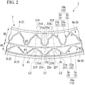
FIG. 2 is an enlarged side view of a main portion of the non-pneumatic tire shown inFIG. 1 . -
FIG. 3 is an enlarged side view of the main portion of the non-pneumatic tire shown inFIG. 2 and is a view showing a state where an external force has been input from a road surface to the non-pneumatic tire. -
FIG. 4 is an enlarged side view of a main portion of a non-pneumatic tire according to a second embodiment of the present invention. - Hereinafter, the configuration of a non-pneumatic tire according to the present embodiment will be described with reference to
FIGS. 1 to 3 . It should be noted that the scale in each of the drawings used in the following description is appropriately changed so that each member is recognizable in terms of size. - As shown in
FIGS. 1 and2 , anon-pneumatic tire 1 is provided with a wheel portion (not shown) attached to an axle and atire portion 7 disposed on the outer periphery of the wheel portion. Thenon-pneumatic tire 1 is used for bicycles, two-wheeled vehicles, automobiles, and the like (hereinafter, these generic names will be simply referred to as vehicles). - Here, the wheel portion is formed in a disc shape, the
tire portion 7 is formed in an annular shape, and the central axes of the wheel portion and thetire portion 7 are positioned on a common axis. This common axis will be referred to as a central axis O1 and the direction that is along the central axis O1 will be referred to as a tire width direction. In addition, in a side view as viewed from the tire width direction, the direction that is around the central axis O1 will be referred to as a tire circumferential direction and the direction that is orthogonal to the central axis O1 will be referred to as a tire radial direction. - The
tire portion 7 is provided with threetubular bodies 2 disposed in a multiple manner at intervals in the tire radial direction and a plurality of elastically deformable connectingmembers 3 interconnecting thetubular bodies 2 and disposed along the tire circumferential direction in anannular space 9 provided between thetubular bodies 2 that are adjacent to each other in the tire radial direction among the threetubular bodies 2. - The three
tubular bodies 2 are disposed coaxially with each other. In the shown example, the central axes of thetubular bodies 2 are disposed coaxially with the central axis O1. Thenon-pneumatic tire 1 is provided with aninner tube 6 positioned on the innermost side in the tire radial direction and attached to the axle, an elastically deformableouter tube 4 positioned on the outermost side in the tire radial direction, and an elastically deformableintermediate tube 8 positioned between theinner tube 6 and theouter tube 4 as the threetubular bodies 2. In other words, the plurality of tubular bodies are provided in order such that one tubular body surrounds another tubular body. - The
inner tube 6 is externally fitted to the wheel portion and attached to the axle via the wheel portion. Theouter tube 4 surrounds theinner tube 6 and theintermediate tube 8 from the outside in the tire radial direction. Atread member 5 is fitted on the outer peripheral surface of theouter tube 4. - The
tread member 5 is formed of, for example, vulcanized rubber in which natural rubber or/and a rubber composition is vulcanized or a thermoplastic material and the like. Examples of the thermoplastic material include a thermoplastic elastomer, a thermoplastic resin, and the like. Examples of the thermoplastic elastomer include the amide-based thermoplastic elastomer (TPA), the ester-based thermoplastic elastomer (TPC), the olefin-based thermoplastic elastomer (TPO), the styrene-based thermoplastic elastomer (TPS), the urethane-based thermoplastic elastomer (TPU), the cross-linked thermoplastic rubber (TPV), the other thermoplastic elastomer (TPZ), and the like defined in Japanese Industrial Standard (JIS) K6418. Examples of the thermoplastic resin include urethane resin, olefin resin, vinyl chloride resin, polyamide resin, and the like. It should be noted that thetread member 5 is preferably formed of vulcanized rubber from the viewpoint of wear resistance. - The
annular space 9 is provided between thetubular bodies 2 that are adjacent to each other in the tire radial direction among the threetubular bodies 2. Theannular space 9 is continuously provided over the entire circumference in the tire circumferential direction. Theannular space 9 has a firstannular space 9a (9) positioned on the outside in the tire radial direction and a secondannular space 9b (9) positioned on the inside in the tire radial direction. The size of theannular space 9 in the tire radial direction gradually increases from theannular space 9 that is positioned on the outside in the tire radial direction toward theannular space 9 that is positioned on the inside in the tire radial direction. The size (width) of the annular space 9 (a connectingring 10 to be described later) in the tire radial direction satisfies H1 < H2 when H1 represents theannular space 9a (9) positioned on the outside in the tire radial direction and H2 represents theannular space 9b (9) positioned on the inside in the tire radial direction. In other words, the interval between theintermediate tube 8 and theinner tube 6 in the tire radial direction is larger than the interval between theintermediate tube 8 and theouter tube 4 in the tire radial direction. In other words, the size of theannular space 9 in the tire radial direction gradually increases from the outside in the tire radial direction toward the inside in the tire radial direction. - The connecting
member 3 has a rigidity at which the connectingmember 3 is not elastically deformed by the weight of thenon-pneumatic tire 1. The connectingmember 3 is disposed in eachannular space 9 in a state where the position of the connectingmember 3 in the tire circumferential direction is shifted. In the plurality of connectingmembers 3 disposed in the sameannular space 9, the positions in the tire circumferential direction do not overlap. In addition, a connectingmember 3a is provided in the firstannular space 9a (9) and a connectingmember 3b is provided in the secondannular space 9b (9). In the side view, the connectingmember 3 is formed in a V shape that opens toward the inside in the tire radial direction. The connectingmember 3 is provided with a pair of connectingplates tubular body 2 and extending in the tire radial direction and separated in the tire circumferential direction from the outside toward the inside in the tire radial direction. - The pair of connecting
plates plates tubular body 2 and are not connected to thetubular body 2 via another component. The connection parts between the front and back surfaces of the pair of connectingplates tubular body 2 are R-chamfered so as to form a circular arc shape (fillet) in the side view. - The pair of connecting
plates plates plates plates member 3 that is on the outside in the tire radial direction. The end portions of the pair of connectingplates member 3 that is on the outside in the tire radial direction. The end portions of the pair of connectingplates member 3 in the tire circumferential direction. - As a result of the above, the shape of each connecting
member 3 in the tire side view is in line symmetry with respect to an imaginary line as an axis of symmetry that passes through the end portion of the connectingmember 3 on the outside in the tire radial direction and the central axis O1 and extends along the tire radial direction. In addition, the tire-circumferential-direction end portions in the connectingmembers 3 that are adjacent to each other in the tire circumferential direction are interconnected and the end portions are disposed at equivalent positions in the tire circumferential direction. In addition, the tire-circumferential-direction end portions in the connectingmembers 3 that are adjacent to each other in the tire circumferential direction may not be interconnected. - The connecting
member 3 is provided with the first connectingplate 21 and the second connectingplate 22 as the pair of connectingplates plate 21, the tire-radial-direction outside end portion (hereinafter, referred to as "first end portion") is positioned closer to one side in the tire circumferential direction than the tire-radial-direction inside end portion (hereinafter, referred to as "second end portion"). In contrast, as for the second connectingplate 22, the tire-radial-direction outside end portion (hereinafter, referred to as "third end portion") is positioned closer to the other side in the tire circumferential direction than the tire-radial-direction inside end portion (hereinafter, referred to as "fourth end portion"). - In the pair of connecting
plates plate 21 is positioned on the other side in the tire circumferential direction with respect to the second connectingplate 22. In the connectingmembers 3 that are adjacent to each other in the tire circumferential direction, the second end portion of the first connectingplate 21 forming the connectingmember 3 positioned on one side in the tire circumferential direction and the fourth end portion of the second connectingplate 22 forming the connectingmember 3 positioned on the other side in the tire circumferential direction are connected to each other. -
Curved portions 21d to 21f and 22d to 22f curved in the tire circumferential direction are formed at the tire-radial-direction intermediate parts of one or both of the connectingplates plates 21 and 22 (parts positioned between the first and second end portions and between the third and fourth end portions). In the present embodiment, the plurality ofcurved portions 21d to 21f and 22d to 22f are formed in both connectingplates plates - In the tire side view in which the
non-pneumatic tire 1 is viewed from the tire width direction, the plurality ofcurved portions 21d to 21f and 22d to 22f are formed along the extension direction in which the first connectingplate 21 and the second connectingplate 22 extend. In the shown example, the plurality ofcurved portions 21d to 21f in the first connectingplate 21 and the plurality ofcurved portions 22d to 22f in the second connectingplate 22 are adjacent to each other in the extension direction and have curve directions opposite to each other in the tire circumferential direction. - The plurality of
curved portions 21d to 21f formed in the first connectingplate 21 have the firstcurved portion 21d curved so as to protrude toward one side in the tire circumferential direction, the secondcurved portion 21e positioned between the firstcurved portion 21d and the first end portion and curved so as to protrude toward the other side in the tire circumferential direction, and the thirdcurved portion 21f positioned between the firstcurved portion 21d and the second end portion and curved so as to protrude toward the other side in the tire circumferential direction. - The plurality of
curved portions 22d to 22f formed in the second connectingplate 22 have the firstcurved portion 22d curved so as to protrude toward the other side in the tire circumferential direction, the secondcurved portion 22e positioned between the firstcurved portion 22d and the third end portion and curved so as to protrude toward one side in the tire circumferential direction, and the thirdcurved portion 22f positioned between the firstcurved portion 22d and the fourth end portion and curved so as to protrude toward one side in the tire circumferential direction. - In the shown example, the first
curved portions curved portions curved portions plate 21 and the second connectingplate 22. - As a result of the above, the first
curved portions curved portions curved portions plate 21 and the second connectingplate 22 have equivalent sizes while protruding in opposite directions in the tire circumferential direction. - The plurality of connecting
members 3 disposed along the tire circumferential direction in the sameannular space 9 form the connectingring 10 interconnecting thetubular bodies 2 adjacent to each other in the tire radial direction over the entire circumference. The connectingring 10 interconnects thetubular bodies 2 so as to be freely displaceable. The size (height, width) of the connectingring 10 in the tire radial direction gradually increases (heightens) from the connectingring 10 that is positioned on the outside in the tire radial direction toward the connectingring 10 that is positioned on the inside in the tire radial direction. In other words, the size of the connectingring 10 in the tire radial direction satisfies H1 < H2 when H1 represents the size of a connectingring 10a (theannular space 9a) positioned on the outside in the tire radial direction and H2 represents the size of a connectingring 10b (theannular space 9b) positioned on the inside in the tire radial direction. In other words, the size of the connectingring 10 in the tire radial direction gradually increases from the outside toward the inside in the tire radial direction. All of the connectingmembers 3 forming the same connectingring 10 have shapes equivalent to each other, have sizes equivalent to each other, and are separately disposed at positions rotationally symmetric with respect to the central axis O1 in eachannular space 9. - In the plurality of connecting
rings 10, the same number of the connectingmembers 3 are provided so as to be disposed at equivalent positions in the tire circumferential direction. As for the connectingmembers 3 corresponding to each other in each of the plurality of connectingrings 10, the tire-circumferential-direction positions of the tire-radial-direction outside end portions in the respective connectingmembers 3 are equivalent and the tire-radial-direction outside end portion of each connectingmember 3 is positioned on a first reference line L1, which extends in the tire radial direction through the central axis O1, in the side view. It should be noted that the imaginary line is positioned on the first reference line L1. In addition, as for the connectingmembers 3 corresponding to each other in each of the plurality of connectingrings 10, the tire-circumferential-direction positions of both tire-circumferential-direction end portions in the respective connectingmembers 3 are also equivalent and both tire-circumferential-direction end portions of each connectingmember 3 are positioned on a second reference line L2 extending in the tire radial direction through the central axis O1. - In the side view, the angle that the pair of connecting
plates member 3 on the outside in the tire radial direction (hereinafter, referred to as "V-shaped angle") gradually decreases from the connectingmember 3 forming the connectingring 10 positioned on the outside in the tire radial direction toward the connectingmember 3 forming the connectingring 10 positioned on the inside in the tire radial direction. The V-shaped angle is formed by a straight line connecting the first end portion and the second end portion of the first connectingplate 21 and a straight line connecting the third end portion and the fourth end portion of the second connectingplate 22 in the side view. As a result, the size (circumferential length) of the connectingmember 3 in the tire circumferential direction gradually decreases from the connectingmember 3 forming the connectingring 10 positioned on the outside in the tire radial direction toward the connectingmember 3 forming the connectingring 10 positioned on the inside in the tire radial direction. θ1 > θ2 is satisfied when the V-shaped angle is θ1 and θ2 in size in the order of the connectingmember 3 of the connectingring 10 positioned on the outside in the tire radial direction and the connectingmember 3 of the connectingring 10 positioned on the inside in the tire radial direction. In other words, θ1 > θ2 is satisfied when the V-shaped angle of the connectingmember 3a (3) of the connectingring 10a (10) positioned on the outside in the tire radial direction is θ1 and the V-shaped angle of the connectingmember 3b (3) of the connectingring 10b (10) positioned on the inside in the tire radial direction is θ2. In other words, the size of the V-shaped angle gradually decreases from the outside in the tire radial direction toward the inside in the tire radial direction. - In addition, the size (height) of the connecting
member 3 in the tire radial direction gradually increases (heightens) from the connectingmember 3 forming the connectingring 10 positioned on the outside in the tire radial direction toward the connectingmember 3 forming the connectingring 10 positioned on the inside in the tire radial direction. - As a result of the above, the size of the connecting
member 3 in the tire radial direction increases, although the size of the connectingmember 3 in the tire circumferential direction decreases, from the connectingmember 3 forming the connectingring 10 positioned on the outside in the tire radial direction toward the connectingmember 3 forming the connectingring 10 positioned on the inside in the tire radial direction. As a result, the length of each of the connectingplates member 3 can be equivalent with ease regardless of the position of the connectingmember 3 in the tire radial direction. - It should be noted that the curvature of each of the
curved portions 21d to 21f and 22d to 22f of the connectingmember 3 gradually increases from the connectingmember 3 forming the connectingring 10 positioned on the outside in the tire radial direction toward the connectingmember 3 forming the connectingring 10 positioned on the inside in the tire radial direction. - Shifted in the tire circumferential direction in the
intermediate tube 8 are the position of connection to the pair of connectingplates intermediate tube 8 from the outside in the tire radial direction (hereinafter, referred to as "outside connection position P1") and the position of connection to the pair of connectingplates intermediate tube 8 from the inside in the tire radial direction (hereinafter, referred to as "inside connection position P2"). The outside connection position P1 is along the tire circumferential direction regarding the part where the second and fourth end portions of the pair of connectingplates 21a (21) and 22a (22) (tire-circumferential-direction end portions of the connecting member 3) are connected on the outer peripheral surface of theintermediate tube 8. The inside connection position P2 is along the tire circumferential direction regarding the part where the first and third end portions of the pair of connectingplates 21b (21) and 22b (22) (tire-radial-direction outside end portions of the connecting member 3) are connected on the inner peripheral surface of theintermediate tube 8. The outside connection position P1 and the inside connection position P2 are alternately disposed in theintermediate tube 8 along the tire circumferential direction. The tire-circumferential-direction interval between the outside connection position P1 and the inside connection position P2 is equivalent over the entire circumference in the tire circumferential direction. - In the present embodiment, the
tubular body 2 and the connectingmember 3 are integrally formed of a thermoplastic resin. As a result, thetire portion 7 can be molded by injection molding and is suitable for mass production. The thermoplastic resin may be one type of resin, a mixture containing two or more types of resins, a mixture containing one or more types of resins and one or more types of elastomers, or the like and the thermoplastic resin may contain an additive such as an anti-aging agent, a plasticizer, a filler, a pigment, and the like. The degree of freedom in terms of design can be ensured for thetire portion 7 by thetubular body 2 and the connectingmember 3 being integrally formed of the thermoplastic resin as described above. - It should be noted that the
tubular body 2 and the connectingmember 3 may be formed separately from each other. In addition, thetubular body 2 and the connectingmember 3 may be formed of a material other than the thermoplastic resin. - The
tire portion 7 and the wheel portion may be integrally formed or may be separately formed. It should be noted that the wheel portion has the function of connecting the axle and thetire portion 7 to each other, thetire portion 7 is elastically deformable, and thetire portion 7 has the function of absorbing vibration transmitted from a ground surface to the axle. The wheel portion and thetire portion 7 may be formed of different materials since the wheel portion and thetire portion 7 have different functions as described above. For example, thetire portion 7 may be formed of a material having a relatively low elastic modulus so that vibration absorption performance is ensured and the wheel portion may be formed of a material larger in elastic modulus than thetire portion 7 so that robustness is ensured. In another example, the weight of the entirenon-pneumatic tire 1 may be reduced by the wheel portion being formed of a material having a relatively small specific gravity. - As described above, in the
non-pneumatic tire 1 according to the present embodiment, both end portions of the pair of connectingplates tubular body 2 and the pair of connectingplates member 3 can be formed in the V shape that opens toward the inside in the tire radial direction in the side view. As a result, each connectingmember 3 as a whole can be flexibly and elastically deformed when, for example, an external force has been input from a road surface to thenon-pneumatic tire 1. - It should be noted that the
curved portions 21d to 21f and 22d to 22f are formed at the intermediate parts of the connectingplates plates member 3 while ensuring the strength of the connectingmember 3. In other words, as shown inFIG. 3 , it is possible to deform the connectingplates curved portions 21d to 21f and 22d to 22f increases when, for example, an external force has been input from a road surface to thenon-pneumatic tire 1. - Further, in the
intermediate tube 8, the outside connection position P1 and the inside connection position P2 are shifted in the tire circumferential direction. As a result, it is also possible to flexibly and elastically deform theintermediate tube 8 by relieving stress concentration as compared with a case where, for example, the outside connection position P1 and the inside connection position P2 in theintermediate tube 8 are positions equivalent to each other in the tire circumferential direction. In other words, as shown inFIG. 3 , theintermediate tube 8 can be elastically deformed with ease toward the inside in the tire radial direction at the outside connection position P1 and theintermediate tube 8 can be elastically deformed with ease toward the outside in the tire radial direction at the inside connection position P2 when, for example, an external force has been input from a road surface to thenon-pneumatic tire 1. It should be noted that the pre-elastic deformation shape of each member is indicated by a two-dot chain line inFIG. 3 . - As described above, each connecting
member 3 as a whole and theintermediate tube 8 can be flexibly and elastically deformed when, for example, an external force has been input from a road surface to thenon-pneumatic tire 1, and thus it is possible to improve ride comfort by reducing the rigidity of thenon-pneumatic tire 1 as a whole. - Further, it is possible to ensure a deformation amount in the
non-pneumatic tire 1 as a whole while reducing the deformation amount of each member by flexibly and elastically deforming theintermediate tube 8 and each connectingmember 3 as a whole. As a result, the strength of thenon-pneumatic tire 1 can be ensured. It should be noted that the deformation during external force input may concentrate on the connectingmember 3 and it may be impossible to ensure the strength of the connectingmember 3 in a case where, for example, theinner tube 6 and theouter tube 4 are directly connected not via theintermediate tube 8 but by the connectingmember 3. In this case, deformation suppression based on an increase in the rigidity of the connectingmember 3 for the purpose of ensuring the strength of the connectingmember 3 may lead to a decline in ride comfort. - In addition, the same number of the connecting
members 3 can be disposed at the equivalent positions in the tire circumferential direction in each of the plurality of connectingrings 10 after each connectingmember 3 is formed in the V shape described above. Accordingly, the outside connection position P1 and the inside connection position P2 in theintermediate tube 8 can be effectively shifted along the tire circumferential direction and theintermediate tube 8 and each connectingmember 3 as a whole can be elastically deformed with more flexibility. - By the way, the circumferential length of the
annular space 9 gradually decreases from theannular space 9 positioned on the outside in the tire radial direction toward theannular space 9 positioned on the inside in the tire radial direction. Accordingly, when the same number of the connectingmembers 3 are provided in each of the plurality of connectingrings 10, the connectingmember 3 becomes smaller in the tire circumferential direction in the connectingring 10 positioned on the inside in the tire radial direction than in the connectingring 10 positioned on the outside in the tire radial direction, and thus it becomes difficult to ensure the lengths of the connectingplates - However, in the present embodiment, the size of the
annular space 9 in the tire radial direction increases from theannular space 9 positioned on the outside in the tire radial direction toward theannular space 9 positioned on the inside in the tire radial direction. Accordingly, the connectingmember 3 can be longer (higher) in the tire radial direction in the connectingring 10 positioned on the inside in the tire radial direction than in the connectingring 10 positioned on the outside in the tire radial direction. As a result, the lengths of the connectingplates member 3 forming each connectingring 10 can be easily and equivalently ensured regardless of the position of the connectingring 10 in the tire radial direction. As a result, the connectingmember 3 can be flexibly deformed in an effective manner and the ride comfort can be reliably enhanced. - In addition, the V-shaped angle gradually decreases from the connecting
member 3 forming the connectingring 10 positioned on the outside in the tire radial direction toward the connectingmember 3 forming the connectingring 10 positioned on the inside in the tire radial direction. Accordingly, it is possible to reduce the size of the connectingmember 3 in the tire circumferential direction while ensuring the lengths of the connectingplates member 3 as described above in the connectingring 10 positioned on the inside in the tire radial direction. As a result, the same number of the connectingmembers 3 as in theannular space 9 having a long circumferential length and positioned on the outside in the tire radial direction can be reliably provided even in theannular space 9 having a short circumferential length and positioned on the inside in the tire radial direction. - Next, a non-pneumatic tire 50 according to a second embodiment of the present invention will be described with reference to
FIG. 4 . - It should be noted that parts of the second embodiment identical to components of the first embodiment will be denoted by the same reference numerals, the identical parts will not be described, and only differences will be described below.
- Four
tubular bodies 2 are provided in the non-pneumatic tire 50 according to the present embodiment. The non-pneumatic tire 50 is provided with oneinner tube 6, oneouter tube 4, and twointermediate tubes 8 as thetubular bodies 2. In addition, an outsideintermediate tube 8a (8) positioned on the outside in the tire radial direction and an insideintermediate tube 8b (8) positioned on the inside in the tire radial direction are the twointermediate tubes 8. As a result, threeannular spaces 9 and three connectingrings 10 are formed. Assuming that the three connectingrings 10 are thefirst ring 10a, thesecond ring 10b, and athird ring 10c in order from the outside toward the inside in the tire radial direction, thefirst ring 10a interconnects theouter tube 4 and theintermediate tube 8, thesecond ring 10b interconnects the intermediate tubes 8 (the outsideintermediate tube 8a (8) and the insideintermediate tube 8b (8)), and thethird ring 10c interconnects theintermediate tube 8 and theinner tube 6. In addition, the connecting members that form thefirst ring 10a, thesecond ring 10b, and thethird ring 10c are referred to as the first connectingmember 3a, the second connectingmember 3b, and a third connectingmember 3c, respectively. Further, the connectingmembers annular space 9a, the secondannular space 9b, and a thirdannular space 9c, respectively. The size of theannular space 9 in the tire radial direction satisfies H1 < H2 < H3 when the size of theannular space 9 in the tire radial direction is H1, H2, and H3 in order from theannular space 9 positioned on the outside in the tire radial direction to theannular space 9 positioned on the inside in the tire radial direction (in the order of theannular spaces annular space 9 in the tire radial direction gradually increases from the outside in the tire radial direction toward the inside in the tire radial direction. In addition, the size of the V-shaped angle satisfies θ1 > θ2 > θ3 when the V-shaped angles of the connectingmembers member 3 of the connectingring 10 positioned on the outside in the tire radial direction to the connectingmember 3 of the connectingring 10 positioned on the inside in the tire radial direction. In other words, the size of the V-shaped angle gradually decreases from the outside in the tire radial direction toward the inside in the tire radial direction. - According to this invention, both end portions of the pair of connecting plates are directly connected to the tubular body and the pair of connecting plates are separated in the tire circumferential direction from the outside toward the inside in the tire radial direction. Accordingly, each connecting member can be formed in the V shape that opens toward the inside in the tire radial direction in the side view as viewed from the tire width direction. As a result, each connecting member as a whole can be flexibly and elastically deformed when, for example, an external force has been input from a road surface to the non-pneumatic tire.
- Further, in the intermediate tube, the outside connection position as the position of connection to the pair of connecting plates connected to the intermediate tube from the outside in the tire radial direction and the inside connection position as the position of connection to the pair of connecting plates connected to the intermediate tube from the inside in the tire radial direction are shifted in the tire circumferential direction. As a result, it is also possible to flexibly and elastically deform the intermediate tube by relieving stress concentration as compared with a case where, for example, the outside connection position and the inside connection position in the intermediate tube are positions equivalent to each other in the tire circumferential direction.
- As described above, each connecting member as a whole and the intermediate tube can be flexibly and elastically deformed when, for example, an external force has been input from a road surface to the non-pneumatic tire, and thus it is possible to improve ride comfort by reducing the rigidity of the non-pneumatic tire as a whole.
- Further, it is possible to ensure a deformation amount in the non-pneumatic tire as a whole while reducing the deformation amount of each member by flexibly and elastically deforming the intermediate tube and each connecting member as a whole. As a result, the strength of the non-pneumatic tire can be ensured. It should be noted that the deformation during external force input may concentrate on the connecting member and it may be impossible to ensure the strength of the connecting member in a case where, for example, the inner tube and the outer tube are directly connected not via the intermediate tube but by the connecting member. In this case, deformation suppression based on an increase in the rigidity of the connecting member for the purpose of ensuring the strength of the connecting member may lead to a decline in ride comfort.
- The plurality of connecting members disposed along the tire circumferential direction in each of the annular spaces form the connecting ring interconnecting the tubular bodies over the entire circumference and the same number of the connecting members are provided so as to be disposed at equivalent positions in the tire circumferential direction in the plurality of connecting rings.
- In this case, the same number of the connecting members can be disposed at the equivalent positions in the tire circumferential direction in each of the plurality of connecting rings after each connecting member is formed in the V shape described above. Accordingly, the outside connection position and the inside connection position in the intermediate tube can be effectively shifted along the tire circumferential direction and the intermediate tube and each connecting member as a whole can be elastically deformed with more flexibility.
- The size of the annular space in the tire radial direction gradually increases from the annular space positioned on the outside in the tire radial direction toward the annular space positioned on the inside in the tire radial direction.
- The circumferential length of the annular space gradually decreases from the annular space positioned on the outside in the tire radial direction toward the annular space positioned on the inside in the tire radial direction. Accordingly, when the same number of the connecting members are provided in each of the plurality of connecting rings, the connecting member becomes smaller in the tire circumferential direction in the connecting ring positioned on the inside in the tire radial direction than in the connecting ring positioned on the outside in the tire radial direction, and thus it becomes difficult to ensure the lengths of the connecting plates.
- However, in this case, the size of the annular space in the tire radial direction increases from the annular space positioned on the outside in the tire radial direction toward the annular space positioned on the inside in the tire radial direction. Accordingly, the connecting member can be longer (higher) in the tire radial direction in the connecting ring positioned on the inside in the tire radial direction than in the connecting ring positioned on the outside in the tire radial direction. As a result, the lengths of the connecting plates of the connecting member forming each connecting ring can be easily and equivalently ensured regardless of the position of the connecting ring in the tire radial direction. As a result, the connecting member can be flexibly deformed in an effective manner and the ride comfort can be reliably enhanced.
- In the side view as viewed from the tire width direction, the angle that the pair of connecting plates form in the end portion of the connecting member on the outside in the tire radial direction gradually decreases from the connecting member forming the connecting ring positioned on the outside in the tire radial direction toward the connecting member forming the connecting ring positioned on the inside in the tire radial direction.
- In this case, in the side view, the angle that the pair of connecting plates form in the end portion of the connecting member on the outside in the tire radial direction gradually decreases from the connecting member forming the connecting ring positioned on the outside in the tire radial direction toward the connecting member forming the connecting ring positioned on the inside in the tire radial direction. Accordingly, it is possible to reduce the size of the connecting member in the tire circumferential direction while ensuring the lengths of the connecting plates of the connecting member as described above in the connecting ring positioned on the inside in the tire radial direction. As a result, the same number of the connecting members as in the annular space having a long circumferential length and positioned on the outside in the tire radial direction can be reliably provided even in the annular space having a short circumferential length and positioned on the inside in the tire radial direction.
- A curved portion curved in the tire circumferential direction may be formed at the tire-radial-direction intermediate part of one or both of the connecting plates of the pair of connecting plates.
- In this case, the curved portion is formed at the intermediate part of the connecting plate and the connecting plate has a plurality of inflection points in the side view. As a result, it is possible to easily deform the connecting member while ensuring the strength of the connecting member and further improve the ride comfort.
- It should be noted that the technical scope of the present invention is not limited to the embodiments described above and various modifications can be made without departing from the scope of the present invention.
- The
curved portions 21d to 21f and 22d to 22f may be omitted and thetread member 5 may be omitted. - The
tubular bodies 2 are not limited to three or four in number and it is possible to appropriately adopt a form in which thetubular bodies 2 are three or more in number. - The size of the
annular space 9 in the tire radial direction may not gradually increase from theannular space 9 positioned on the outside in the tire radial direction toward theannular space 9 positioned on the inside in the tire radial direction. - In addition, it is possible to appropriately replace the components in the above-described embodiments with known components without departing from the scope of the present invention and the above-described modified examples may be appropriately combined.
- According to the non-pneumatic tire described above, ride comfort can be improved.
-
- 1, 50
- Non-pneumatic tire
- 2
- Tubular body
- 3, 3a, 3b, 3c
- Connecting member
- 4
- Outer tube
- 6
- Inner tube
- 8, 8a, 8b
- Intermediate tube
- 9, 9a, 9b, 9c
- Annular space
- 10, 10a, 10b, 10c
- Connecting ring
- 21, 22, 21a, 22a, 21b, 22b, 21c, 22c
- Connecting plate
- 21d, 21e, 21f, 22d, 22e, 22f
- Curved portion
Claims (5)
- A non-pneumatic tire comprising:three or more tubular bodies coaxially disposed at intervals in a tire radial direction; anda plurality of elastically deformable connecting members interconnecting the tubular bodies and disposed along a tire circumferential direction in each annular space provided between the tubular bodies adjacent to each other in the tire radial direction among the three or more tubular bodies, whereinthe three or more tubular bodies are provided with an inner tube positioned on an innermost side in the tire radial direction and attached to an axle, an outer tube positioned on an outermost side in the tire radial direction, and an elastically deformable intermediate tube positioned between the inner tube and the outer tube,each of the connecting members is provided with a pair of connecting plates having both end portions in the tire radial direction directly connected to the tubular body and extending so as to be separated in the tire circumferential direction from an outside toward an inside in the tire radial direction, anda position of connection to the pair of connecting plates connected to the intermediate tube from the outside in the tire radial direction and a position of connection to the pair of connecting plates connected to the intermediate tube from the inside in the tire radial direction are shifted in the tire circumferential direction in the intermediate tube.
- The non-pneumatic tire according to claim 1, wherein
the plurality of connecting members disposed along the tire circumferential direction in each of the annular spaces form a connecting ring interconnecting the tubular bodies over an entire circumference, and
the same number of the connecting members are provided in each of a plurality of the connecting rings so as to be disposed at positions equivalent in the tire circumferential direction. - The non-pneumatic tire according to claim 2, wherein a size of the annular space in the tire radial direction gradually increases from the annular space positioned on the outside in the tire radial direction toward the annular space positioned on the inside in the tire radial direction.
- The non-pneumatic tire according to claim 3, wherein an angle formed by the pair of connecting plates in an end portion of the connecting member on the outside in the tire radial direction gradually decreases from the connecting member forming the connecting ring positioned on the outside in the tire radial direction toward the connecting member forming the connecting ring positioned on the inside in the tire radial direction in a side view as viewed from a tire width direction.
- The non-pneumatic tire according to any one of claims 1 to 4, wherein a curved portion curved in the tire circumferential direction is formed at a tire-radial direction intermediate part of one or both the connecting plates of the pair of connecting plates.
Applications Claiming Priority (2)
| Application Number | Priority Date | Filing Date | Title |
|---|---|---|---|
| JP2017094666A JP6842361B2 (en) | 2017-05-11 | 2017-05-11 | Non-pneumatic tires |
| PCT/JP2018/015370 WO2018207543A1 (en) | 2017-05-11 | 2018-04-12 | Non-pneumatic tire |
Publications (2)
| Publication Number | Publication Date |
|---|---|
| EP3623173A1 true EP3623173A1 (en) | 2020-03-18 |
| EP3623173A4 EP3623173A4 (en) | 2020-11-25 |
Family
ID=64104492
Family Applications (1)
| Application Number | Title | Priority Date | Filing Date |
|---|---|---|---|
| EP18797535.4A Withdrawn EP3623173A4 (en) | 2017-05-11 | 2018-04-12 | Non-pneumatic tire |
Country Status (5)
| Country | Link |
|---|---|
| US (1) | US11427030B2 (en) |
| EP (1) | EP3623173A4 (en) |
| JP (1) | JP6842361B2 (en) |
| CN (1) | CN110612218A (en) |
| WO (1) | WO2018207543A1 (en) |
Cited By (1)
| Publication number | Priority date | Publication date | Assignee | Title |
|---|---|---|---|---|
| CN112297715A (en) * | 2020-11-09 | 2021-02-02 | 芜湖集拓实心胎有限公司 | High-strength inflation-free solid tire |
Families Citing this family (5)
| Publication number | Priority date | Publication date | Assignee | Title |
|---|---|---|---|---|
| CN113260520B (en) * | 2018-12-28 | 2023-11-03 | 普利司通美国轮胎运营有限责任公司 | Metal web for non-pneumatic tires and method of making same |
| WO2020139680A1 (en) * | 2018-12-28 | 2020-07-02 | Bridgestone Americas Tire Operations, Llc | Web structure for non-pneumatic tire and method of making same |
| WO2021137993A1 (en) * | 2019-12-30 | 2021-07-08 | Bridgestone Americas Tire Operations, Llc | Non-pneumatic tire having reinforced support structure and method of making same |
| CN113085446A (en) * | 2021-03-29 | 2021-07-09 | 南京航空航天大学 | Non-pneumatic elastic tire |
| CN113246661B (en) * | 2021-06-25 | 2022-04-26 | 季华实验室 | Support body, elastic support assembly and tire |
Family Cites Families (21)
| Publication number | Priority date | Publication date | Assignee | Title |
|---|---|---|---|---|
| US1430657A (en) | 1921-04-23 | 1922-10-03 | Kennedy Donald Stewart | Resilient wheel |
| JPH01311902A (en) * | 1988-06-10 | 1989-12-15 | Yokohama Rubber Co Ltd:The | Non-pneumatic type tire |
| WO2007057975A1 (en) * | 2005-11-21 | 2007-05-24 | Space Inc. | Tire with elastic structure |
| US8544515B2 (en) * | 2008-11-10 | 2013-10-01 | Mkp Structural Design Associates, Inc. | Ultralightweight runflat tires based upon negative poisson ratio (NPR) auxetic structures |
| JP4674253B2 (en) * | 2008-11-28 | 2011-04-20 | 東洋ゴム工業株式会社 | Non-pneumatic tire |
| CN201619392U (en) | 2009-12-29 | 2010-11-03 | 广州大学 | air-free wheel |
| US8555941B2 (en) * | 2010-08-12 | 2013-10-15 | The Boeing Company | Non-pneumatic survivable tire, cover and fabrication processes |
| KR101043001B1 (en) * | 2010-09-14 | 2011-06-21 | 한국타이어 주식회사 | Airless tire |
| JP6025315B2 (en) * | 2011-10-05 | 2016-11-16 | 東洋ゴム工業株式会社 | Non-pneumatic tire |
| KR101411103B1 (en) * | 2013-11-06 | 2014-06-27 | 한국타이어 주식회사 | Non-pneumatic tire |
| US9908369B2 (en) * | 2014-03-10 | 2018-03-06 | Mkp Structural Design Associates, Inc. | Airless and runflat tire structures, components and assembly techniques |
| JP6302355B2 (en) * | 2014-05-22 | 2018-03-28 | 住友ゴム工業株式会社 | Non-pneumatic tire |
| US10406860B2 (en) | 2014-12-03 | 2019-09-10 | Bridgestone Americas Tire Operations, Llc | Non-pneumatic tire |
| EP3240699A1 (en) * | 2014-12-31 | 2017-11-08 | Compagnie Générale des Etablissements Michelin | Non-pneumatic tire with multi-connection connecting elements |
| KR101722715B1 (en) | 2015-03-04 | 2017-04-03 | 한국타이어 주식회사 | Non-pneumatic tire |
| CN105109279B (en) * | 2015-08-19 | 2017-11-07 | 张永汉 | Non-inflatable tyre |
| CN108136835B (en) | 2015-10-09 | 2019-11-22 | 株式会社普利司通 | Non-pneumatic tires |
| JP2017094666A (en) | 2015-11-27 | 2017-06-01 | 株式会社クラレ | Composite sheet, processed composite sheet and method for producing resin sheet for nailing |
| WO2017116385A1 (en) * | 2015-12-28 | 2017-07-06 | Compagnie Generale Des Etablissements Michelin | Method of forming non-pneumatic tire including pressure application between an intermediate section and an outer shear band ring |
| WO2017116384A1 (en) * | 2015-12-28 | 2017-07-06 | Campagnie Generale Des Etablissements Michelin | Method of forming non-pneumatic tire using support structure deformation |
| AU2017266840A1 (en) * | 2016-05-18 | 2018-01-04 | Lanxess Solutions Us Inc. | Non-pneumatic elastomeric tire with crossed spoke sidewalls |
-
2017
- 2017-05-11 JP JP2017094666A patent/JP6842361B2/en active Active
-
2018
- 2018-04-12 WO PCT/JP2018/015370 patent/WO2018207543A1/en not_active Ceased
- 2018-04-12 EP EP18797535.4A patent/EP3623173A4/en not_active Withdrawn
- 2018-04-12 US US16/611,997 patent/US11427030B2/en active Active
- 2018-04-12 CN CN201880030669.1A patent/CN110612218A/en active Pending
Cited By (1)
| Publication number | Priority date | Publication date | Assignee | Title |
|---|---|---|---|---|
| CN112297715A (en) * | 2020-11-09 | 2021-02-02 | 芜湖集拓实心胎有限公司 | High-strength inflation-free solid tire |
Also Published As
| Publication number | Publication date |
|---|---|
| JP6842361B2 (en) | 2021-03-17 |
| EP3623173A4 (en) | 2020-11-25 |
| US20210138836A1 (en) | 2021-05-13 |
| US11427030B2 (en) | 2022-08-30 |
| WO2018207543A1 (en) | 2018-11-15 |
| JP2018188098A (en) | 2018-11-29 |
| CN110612218A (en) | 2019-12-24 |
Similar Documents
| Publication | Publication Date | Title |
|---|---|---|
| EP3623173A1 (en) | Non-pneumatic tire | |
| EP3623174B1 (en) | Non-pneumatic tire | |
| EP3623175B1 (en) | Non-pneumatic tire | |
| KR101839537B1 (en) | Non pneumatic tire | |
| EP2769852B1 (en) | Non-pneumatic tire | |
| JP6746598B2 (en) | Non-pneumatic tire | |
| KR101841655B1 (en) | Non pneumatic tire | |
| WO2015141579A1 (en) | Non-pneumatic tire | |
| EP3888936B1 (en) | Non-pneumatic tire | |
| WO2016098477A1 (en) | Non-pneumatic tire | |
| JP2013079037A (en) | Non-pneumatic tire | |
| EP3888937B1 (en) | Non-pneumatic tire | |
| KR101818660B1 (en) | Non pneumatic tire | |
| KR101818664B1 (en) | Non pneumatic tire | |
| KR20180025749A (en) | Non pneumatic tire | |
| CN112677708B (en) | Non-pneumatic tire | |
| JP2024057476A (en) | Tire and rim assembly | |
| KR20180025713A (en) | Non pneumatic tire |
Legal Events
| Date | Code | Title | Description |
|---|---|---|---|
| STAA | Information on the status of an ep patent application or granted ep patent |
Free format text: STATUS: THE INTERNATIONAL PUBLICATION HAS BEEN MADE |
|
| PUAI | Public reference made under article 153(3) epc to a published international application that has entered the european phase |
Free format text: ORIGINAL CODE: 0009012 |
|
| STAA | Information on the status of an ep patent application or granted ep patent |
Free format text: STATUS: REQUEST FOR EXAMINATION WAS MADE |
|
| 17P | Request for examination filed |
Effective date: 20191114 |
|
| AK | Designated contracting states |
Kind code of ref document: A1 Designated state(s): AL AT BE BG CH CY CZ DE DK EE ES FI FR GB GR HR HU IE IS IT LI LT LU LV MC MK MT NL NO PL PT RO RS SE SI SK SM TR |
|
| AX | Request for extension of the european patent |
Extension state: BA ME |
|
| DAV | Request for validation of the european patent (deleted) | ||
| DAX | Request for extension of the european patent (deleted) | ||
| A4 | Supplementary search report drawn up and despatched |
Effective date: 20201026 |
|
| RIC1 | Information provided on ipc code assigned before grant |
Ipc: B60C 7/18 20060101ALI20201020BHEP Ipc: B60C 7/14 20060101ALI20201020BHEP Ipc: B60B 9/02 20060101ALI20201020BHEP Ipc: B60C 7/00 20060101AFI20201020BHEP Ipc: B60C 7/20 20060101ALI20201020BHEP |
|
| STAA | Information on the status of an ep patent application or granted ep patent |
Free format text: STATUS: THE APPLICATION IS DEEMED TO BE WITHDRAWN |
|
| 18D | Application deemed to be withdrawn |
Effective date: 20210526 |