EP3623166B1 - Image transfer sheet, method for producing image transfer sheet, and image transfer method - Google Patents
Image transfer sheet, method for producing image transfer sheet, and image transfer method Download PDFInfo
- Publication number
- EP3623166B1 EP3623166B1 EP18914932.1A EP18914932A EP3623166B1 EP 3623166 B1 EP3623166 B1 EP 3623166B1 EP 18914932 A EP18914932 A EP 18914932A EP 3623166 B1 EP3623166 B1 EP 3623166B1
- Authority
- EP
- European Patent Office
- Prior art keywords
- image
- layer
- glue layer
- protrusions
- transfer
- Prior art date
- Legal status (The legal status is an assumption and is not a legal conclusion. Google has not performed a legal analysis and makes no representation as to the accuracy of the status listed.)
- Active
Links
Images


Classifications
-
- B—PERFORMING OPERATIONS; TRANSPORTING
- B41—PRINTING; LINING MACHINES; TYPEWRITERS; STAMPS
- B41M—PRINTING, DUPLICATING, MARKING, OR COPYING PROCESSES; COLOUR PRINTING
- B41M5/00—Duplicating or marking methods; Sheet materials for use therein
- B41M5/025—Duplicating or marking methods; Sheet materials for use therein by transferring ink from the master sheet
- B41M5/03—Duplicating or marking methods; Sheet materials for use therein by transferring ink from the master sheet by pressure
-
- B—PERFORMING OPERATIONS; TRANSPORTING
- B44—DECORATIVE ARTS
- B44C—PRODUCING DECORATIVE EFFECTS; MOSAICS; TARSIA WORK; PAPERHANGING
- B44C1/00—Processes, not specifically provided for elsewhere, for producing decorative surface effects
- B44C1/16—Processes, not specifically provided for elsewhere, for producing decorative surface effects for applying transfer pictures or the like
- B44C1/165—Processes, not specifically provided for elsewhere, for producing decorative surface effects for applying transfer pictures or the like for decalcomanias; sheet material therefor
- B44C1/17—Dry transfer
- B44C1/1733—Decalcomanias applied under pressure only, e.g. provided with a pressure sensitive adhesive
- B44C1/1745—Decalcomanias applied under pressure only, e.g. provided with a pressure sensitive adhesive using an intermediate support
-
- B—PERFORMING OPERATIONS; TRANSPORTING
- B41—PRINTING; LINING MACHINES; TYPEWRITERS; STAMPS
- B41M—PRINTING, DUPLICATING, MARKING, OR COPYING PROCESSES; COLOUR PRINTING
- B41M3/00—Printing processes to produce particular kinds of printed work, e.g. patterns
- B41M3/12—Transfer pictures or the like, e.g. decalcomanias
-
- B—PERFORMING OPERATIONS; TRANSPORTING
- B41—PRINTING; LINING MACHINES; TYPEWRITERS; STAMPS
- B41M—PRINTING, DUPLICATING, MARKING, OR COPYING PROCESSES; COLOUR PRINTING
- B41M5/00—Duplicating or marking methods; Sheet materials for use therein
- B41M5/0023—Digital printing methods characterised by the inks used
-
- B—PERFORMING OPERATIONS; TRANSPORTING
- B44—DECORATIVE ARTS
- B44C—PRODUCING DECORATIVE EFFECTS; MOSAICS; TARSIA WORK; PAPERHANGING
- B44C1/00—Processes, not specifically provided for elsewhere, for producing decorative surface effects
- B44C1/16—Processes, not specifically provided for elsewhere, for producing decorative surface effects for applying transfer pictures or the like
- B44C1/165—Processes, not specifically provided for elsewhere, for producing decorative surface effects for applying transfer pictures or the like for decalcomanias; sheet material therefor
- B44C1/17—Dry transfer
- B44C1/1733—Decalcomanias applied under pressure only, e.g. provided with a pressure sensitive adhesive
-
- C—CHEMISTRY; METALLURGY
- C09—DYES; PAINTS; POLISHES; NATURAL RESINS; ADHESIVES; COMPOSITIONS NOT OTHERWISE PROVIDED FOR; APPLICATIONS OF MATERIALS NOT OTHERWISE PROVIDED FOR
- C09D—COATING COMPOSITIONS, e.g. PAINTS, VARNISHES OR LACQUERS; FILLING PASTES; CHEMICAL PAINT OR INK REMOVERS; INKS; CORRECTING FLUIDS; WOODSTAINS; PASTES OR SOLIDS FOR COLOURING OR PRINTING; USE OF MATERIALS THEREFOR
- C09D11/00—Inks
- C09D11/02—Printing inks
- C09D11/10—Printing inks based on artificial resins
- C09D11/101—Inks specially adapted for printing processes involving curing by wave energy or particle radiation, e.g. with UV-curing following the printing
-
- C—CHEMISTRY; METALLURGY
- C09—DYES; PAINTS; POLISHES; NATURAL RESINS; ADHESIVES; COMPOSITIONS NOT OTHERWISE PROVIDED FOR; APPLICATIONS OF MATERIALS NOT OTHERWISE PROVIDED FOR
- C09J—ADHESIVES; NON-MECHANICAL ASPECTS OF ADHESIVE PROCESSES IN GENERAL; ADHESIVE PROCESSES NOT PROVIDED FOR ELSEWHERE; USE OF MATERIALS AS ADHESIVES
- C09J7/00—Adhesives in the form of films or foils
- C09J7/30—Adhesives in the form of films or foils characterised by the adhesive composition
- C09J7/38—Pressure-sensitive adhesives [PSA]
-
- C—CHEMISTRY; METALLURGY
- C09—DYES; PAINTS; POLISHES; NATURAL RESINS; ADHESIVES; COMPOSITIONS NOT OTHERWISE PROVIDED FOR; APPLICATIONS OF MATERIALS NOT OTHERWISE PROVIDED FOR
- C09J—ADHESIVES; NON-MECHANICAL ASPECTS OF ADHESIVE PROCESSES IN GENERAL; ADHESIVE PROCESSES NOT PROVIDED FOR ELSEWHERE; USE OF MATERIALS AS ADHESIVES
- C09J7/00—Adhesives in the form of films or foils
- C09J7/40—Adhesives in the form of films or foils characterised by release liners
- C09J7/403—Adhesives in the form of films or foils characterised by release liners characterised by the structure of the release feature
-
- C—CHEMISTRY; METALLURGY
- C09—DYES; PAINTS; POLISHES; NATURAL RESINS; ADHESIVES; COMPOSITIONS NOT OTHERWISE PROVIDED FOR; APPLICATIONS OF MATERIALS NOT OTHERWISE PROVIDED FOR
- C09J—ADHESIVES; NON-MECHANICAL ASPECTS OF ADHESIVE PROCESSES IN GENERAL; ADHESIVE PROCESSES NOT PROVIDED FOR ELSEWHERE; USE OF MATERIALS AS ADHESIVES
- C09J2203/00—Applications of adhesives in processes or use of adhesives in the form of films or foils
- C09J2203/334—Applications of adhesives in processes or use of adhesives in the form of films or foils as a label
-
- C—CHEMISTRY; METALLURGY
- C09—DYES; PAINTS; POLISHES; NATURAL RESINS; ADHESIVES; COMPOSITIONS NOT OTHERWISE PROVIDED FOR; APPLICATIONS OF MATERIALS NOT OTHERWISE PROVIDED FOR
- C09J—ADHESIVES; NON-MECHANICAL ASPECTS OF ADHESIVE PROCESSES IN GENERAL; ADHESIVE PROCESSES NOT PROVIDED FOR ELSEWHERE; USE OF MATERIALS AS ADHESIVES
- C09J2301/00—Additional features of adhesives in the form of films or foils
- C09J2301/20—Additional features of adhesives in the form of films or foils characterized by the structural features of the adhesive itself
- C09J2301/204—Additional features of adhesives in the form of films or foils characterized by the structural features of the adhesive itself the adhesive coating being discontinuous
Definitions
- the present invention relates to an image transfer sheet for transferring any image onto a transfer target object; and a method for manufacturing the image transfer sheet or a method for transferring an image onto a transfer target object using the image transfer sheet.
- Technologies for transferring an image onto a surface of an item, on which it is difficult to print an image directly include a transfer technique with a substrate, wherein an image layer is printed on a transparent thin film-like substrate provided with an adhesive layer on its back surface, and wherein the entire substrate is affixed onto an item surface; and a transfer technique without a substrate, wherein eventually only an image layer is transferred directly onto an item surface.
- the former technique is generally known by "image stickers,” “cutting sheets,” etc., wherein the transferred image is spaced from the item surface by the interposing substrate thickness, thereby generating an uneven image surface as a result.
- work is required to remove unwanted substrate parts bearing no image before or after the image transfer using a tool such as a cutting plotter.
- the transfer technique without a substrate enables a high-quality image transfer as if the transferred image was directly printed on an item surface, and this technique does not require the work to remove the non-image part of the substrate.
- Known transfer techniques without a substrate include the water transfer, the thermal transfer, the sublimation transfer, the dry transfer, etc.
- the dry transfer is performed by affixing and pressing an image transfer sheet onto a surface of a transfer target object, wherein the image transfer sheet is defined by providing an image layer on the lower surface of a transfer film and applying adhesive thereover, and transferring only the image layer onto the transfer target object surface by adhesion, wherein no water or heat is used to allow high-quality image transfer.
- the present inventors conducted research of the transfer technique without a substrate, and developed and received a patent right for an image transfer sheet, a method for manufacturing the image transfer sheet and a method for transferring an image using the method for manufacturing the image transfer sheet described in Patent Document 1 ( WO/2017/204289 ).
- the image transfer sheet according to the present patent invention is defined by providing an image layer in part of an area between a transfer film as an upper layer and a glue layer as a lower layer, and releasably gluing release paper onto the lower glue layer, wherein the transfer film is configured to be releasable from the image layer, but easily adhesive to the glue layer.
- Patent Document 1 JP-A-2017-209931 ( WO/2017/204289 ) US20160032149 discloses a decal is suitable for application to an aircraft structure that is covered with an incompletely cured base coat of paint.
- the decal has a polyester film with an adhesive applied to a first side.
- a release layer is applied to the polyester film and comprises a pattern engaging the adhesive to form a plurality of grooves in the adhesive layer.
- honeycomb-shaped protrusions described in US20160032149 eliminate large bubbles when transferring a large-sized, low-definition image such as an aircraft body decal, but small bubbles are not completely eliminated.
- the image transfer sheet according to the invention is based on a reversed concept to print an image layer of a normal image directly on a surface of a glue layer of a glued sheet prepared in advance, and then, cover the glued sheet with a transfer film to complete an image transfer sheet.
- Such an improvement solved problems such as the difficulty in even application of the glue layer during the manufacturing stage of conventional dry image transfer sheets and/or the laborious removal of the glue left on the part bearing no image layer after the image transfer.
- the image transfer sheet according to the invention allowed transferring of an image layer with a three-dimensional feel by forming the image layer using the UV printing. Since the normal image is directly printed on the glue layer surface, the raised printed surface specific to the UV printing was enabled and the problematic air bubbles in and wrinkles of the image layer, often seen in the UV printing, have been successfully prevented.
- the above-described image transfer sheet still had an unresolved issue of air left between the transfer target object and the glue layer, generating air bubbles during the image transfer onto an item. Since the image transfer sheet is ultimately affixed onto the transfer target object by hand, it is difficult to completely prevent the air bubbles from forming. Air bubbles not only compromise the aesthetic and quality of the transferred image, but also make the image layer susceptible to peel-off when the air bubbles form on the outer edge of the transferred image. Also, the air bubbles tend to form more as the size of transferred image increases and when the surface of the transfer target object is curved.
- the purpose of the present invention is to provide an image transfer sheet for leaving no air bubbles between an image layer and a transfer target object, a method for manufacturing the image transfer sheet and a method for transferring an image.
- an image transfer sheet of Claim 1 of the present invention comprises an image layer in part of an area between a transfer film as an upper layer and a glue layer as a lower layer, and the image transfer sheet is defined by the glue layer, a lower surface of which being provided with many individually independent fine protrusions in the entire lower surface, and a release paper releasably glued to the lower surface of the glue layer, wherein the transfer film is releasable from the image layer and easily adhesive to the glue layer, and wherein a lower surface of the transfer film is in contact with the image layer where there is the image layer, and is in contact with the glue layer where there is no image layer.
- the transfer film as the upper layer is preferably transparent PET (polyethylene terephthalate) film with a surface processed to be releasable, but is not limited by it and may be any film whose lower surface is releasable from the image layer and easily adhesive to the glue layer.
- the glue is common pressure-sensitive adhesive containing acrylic resin as its main component
- the transfer film is preferably film with the same acrylic resin.
- the shape of the many fine protrusions on the lower surface of the glue layer may be either dot-like or line-like, but in either way, according to the invention the height of the protrusions is 5-20 ⁇ m, when the protrusions are dot-like, the diameter and the interval between adjacent dot-like protrusions are 0.2 mm-1.0 mm, and when the protrusions are line-like, the line width and the interval between adjacent line-like protrusions are also at least 0.2-1.0 mm.
- the lower surface of the glue layer having the protrusions is exposed by peeling and removing the releasable release paper from the image transfer sheet.
- the image transfer sheet is affixed onto the transfer target object by the glue layer adhesion.
- the image layer remains on the glue layer where there is the image layer, from which the transfer film is releasable.
- the glue layer remains glued to the lower surface of the transfer file, and peeled and removed from the surface of the transfer target object.
- the image layer remains glued onto the surface of the transfer target object by the glue layer, to thereby complete the image transfer.
- the invention of Claim 2 is the image transfer sheet of Claim 1, wherein the image layer is ink printed on an upper surface of the glue layer by an inkjet printer.
- the invention of Claim 3 is the image transfer sheet of Claim 2, wherein the image layer is UV ink printed on the upper surface of the glue layer by a UV printer.
- Non-contact printers are inkjet printers, UV printers, and the like, and are a type of printers which drop ink directly onto the printing surface without any interposing plate material or transfer body directly in contact with the printing surface.
- the image layer according to the present invention is glued to the transfer target object via the glue layer as the ink particles are dropped and deposited on the upper surface of the glue layer, and dried and cured to form a film.
- the UV ink is formulated with a photoinitiator which triggers a photopolymerization reaction by UV light, monomers/oligomers which polymerize by the photopolymerization reaction and pigments as dyes.
- the invention of Claim 4 is a method for manufacturing an image transfer sheet, the method comprising the steps of: forming a glue layer having many individually independent fine protrusions, having the shape and dimensions as described above, by pressure-gluing a glued sheet, defined by a substrate and a glue layer provided on a lower surface of the substrate, onto an upper surface of a release paper, having many fine recesses, and subsequently peeling and removing the substrate and exposing the glue layer; printing ink on the exposed upper surface of the glue layer by a non-contact printer to thereby provide an image layer on part of the glue layer; and affixing a transfer film on the glue layer provided with the image layer, wherein the transfer film is releasable from the image layer and easily adhesive to the glue layer, and causing the transfer film to contact with a lower surface of the transfer film onto the image layer where there is the image layer, and with the glue layer where there is no image layer.
- the invention of Claim 5 is the method for manufacturing the image transfer sheet of Claim 4, where
- the invention of Claim 6 is an image transfer method, using the image transfer sheet manufactured by the method of Claim 4, comprising the steps of: peeling and removing only the release paper from the image transfer sheet; pressure-gluing the lower surface of the glue layer of the image transfer sheet, with the release paper removed, onto a transfer target object; and peeling and removing the transfer film from the image transfer sheet pressure-glued to the transfer target object.
- the invention of Claim 7 is the image transfer method of Claim 6, wherein the image layer is UV ink printed on the upper surface of the glue layer by a UV printer.
- the present invention provides an effect in which image transfer work susceptible to air bubbles with the conventional art, such as transferring a relatively large image, image transfer onto a transfer target object with a curved surface, etc. may be performed easily and reliably.
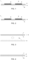
- Fig. 1 is a cross-sectional view showing an example of an image transfer sheet 1 according to a first embodiment of the present invention
- Fig. 2 is a cross-sectional view showing an example of an image transfer sheet 2 according to a second embodiment of the present invention.
- the image transfer sheets 1, 2 have different cross sectional shapes for release paper 13 depending on the different manufacturing methods, but otherwise have a common structure.
- the image transfer sheet 1 comprises an image layer 15 between a transfer film 16 as an upper layer and a glue layer 12 as a lower layer, and the glue layer 12 is defined by having its lower surface releasably glued to an upper surface of the release paper 13.
- the release paper 13 according to the first embodiment is provided with many individually independent fine recesses 13a across its upper surface, and the lower surface of the glue layer 12 has many individually independent fine protrusions 12a formed thereon so that the protrusions 12a mate with the recesses 13a.
- the image layer 15 is printed directly on the upper surface of the glue layer 12 by a non-contact printer such as an inkjet printer, an UV printer or the like, wherein in the case of an inkjet printer, the image layer 15 is an ink layer, and wherein in the case of an UV printer, the image layer 15 is an UV ink layer which has been dried and cured into a thin film-like form through the photopolymerization reaction by UV radiation during the printing.
- a non-contact printer such as an inkjet printer, an UV printer or the like
- the image layer 15 is an ink layer
- the image layer 15 is an UV ink layer which has been dried and cured into a thin film-like form through the photopolymerization reaction by UV radiation during the printing.
- the material of the transfer film 16 is preferably transparent acrylic resin if the glue component of the glue layer 12 is acrylic adhesive as described below, but not necessarily limited to acrylic resin and may be any material releasable from the image layer 15 and easily adhesive to the glue layer 12. Also with a transparent transfer film 16, the image shape and colors may be visually recognized through the surface of the image transfer sheet 1, and therefore, it will be easier to perform positioning and color matching of the transparent transfer film 16 against a transfer target object O.
- the glue layer 12 is, for example, a layer of pressure-sensitive adhesive formulated by acrylic resin and tackifier, and may have any thickness, but preferably of 10-100 ⁇ m, in particular, about 30 ⁇ m.
- the release paper 13 has a silicon film or the like at least on its upper surface, and the release paper 13 is releasable from the glue layer 12 and easily peels off at a normal temperature.
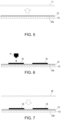
- Fig. 3-Fig. 7 are simplified cross-sectional views showing a method for manufacturing the image transfer sheet 1 according to the first embodiment of the present invention step by step.
- Fig. 3-Fig. 5 show the glue layer forming steps, wherein a glued sheet 10, defined by the glue layer 12 provided on the lower surface of a substrate 11, is pressure-glued to the release paper 13, provided with the many fine recesses 13a across the upper surface of the release paper 13 ( Fig. 3 ) to cause the lower surface of the glue layer 12 to enter into the recesses 13a to form the many independent fine protrusions 12a ( Fig. 4 ), and subsequently the substrate 11 is peeled and removed to expose the upper surface of the glue layer 12 ( Fig. 5 ).
- pressure-sensitive adhesive consisting of acrylic resin, polyolefin fiber, tackifier may be used as the glue layer 12; and ready-made pressure-sensitive double-sided adhesive tape using siliconized glassine paper may be used as the substrate 11.
- the release paper 13 with the many fine recesses 13a in the upper surface thereof may be made by embossing the release paper 13 itself to provide the recesses 13a as illustrated, or, when siliconizing and conferring the releasability to the substrate surface of the release paper during its manufacturing, the silicon film may be embossed before it solidifies to provide the recesses 13a.
- Fig. 6 shows the printing steps, wherein an image layer 15 is printed directly on the upper surface of the glue layer 12 by a non-contact printer.
- the release paper 13 provided with the glue layer 12 is set in the non-contact printer, and then, ink of an arbitrary color is sprayed and printed directly onto the upper surface of the glue layer 12 from a printer head P.
- ink particles are dried and cured through the photopolymerization reaction to thereby form a film-like image layer 15.
- the UV ink particles adhering to the glue layer 12 are dried and cured after they form sealing contact with the upper surface's recesses/protrusions of the glue layer 12, the UV ink particles are fixedly attached to the glue layer 12. Also, since the image layer 13 is printed as a normal image, performing the thick printing as a UV printing characteristic allows any printing thickness with a three-dimensional feel within specifications of the printer in use, and applying the thick printing for only a specific part of the printed image enables creating an accent to the image's three-dimensional feel.
- Fig. 7 shows the affixing step, wherein, after the image layer 15 has been dried and fixed, the transfer film 16 is affixed onto the glue layer 12, which includes the image layer 15, with the transfer film 16 covering the range of the entire image, to thereby complete the image transfer sheet 1 shown in Fig. 1 .
- the completed image transfer sheet 1 may be handled in a similar manner to that of the conventional stickers, and may be regarded as a product allowing transfer and printing of only images.
- Figs. 8-9 are simplified cross-sectional views showing the steps of transferring the image layer 15 onto the surface of the transfer target object O.
- Fig. 8 shows the step of peeling and removing the release paper, wherein the release paper 13 is peeled and removed from the image transfer sheet 1.
- the many independent fine protrusions 12a are formed corresponding to the recesses 13a in the upper surface of the release paper 13.
- Fig. 9 is a cross-sectional view showing the pressure-gluing steps of positioning the image transfer sheet 1 on the surface of a desired transfer target object O after the release paper 13 is peeled and removed, and pressure-gluing the lower surface of the glue layer 12 upon the transfer target object O.
- the lower surface of the glue layer 12 consisting of pressure-sensitive adhesive is glued onto the surface of the transfer target object O, but at this time, it is desired to apply pressure only over the range of the image layer 15.
- This pressure may be applied through rubbing by finger tips, but in order to prevent wrinkling and/or deformation of the image layer 15, it is desirable to use a roller, a squeegee (spatula) or the like having even, smooth and appropriate resiliency to apply an uniform pressure.
- Fig. 10 is a cross-sectional view showing the film peeling step, wherein the transfer film 16 is peeled off after pressure-gluing of the image transfer sheet 1.
- the transfer film 16 is peeled off after the image transfer sheet 1 is pressure-glued, the image layer 15, being glued to the glue layer 12, remains on the surface of the transfer target object O, to thereby complete the image transfer.
- the glue layer 12 in the range without the image layer 15 is glued to the transfer film 16 and is removed from the surface of the transfer target object O, extra glue outside of the image may be prevented from remaining on the transfer target object O.
- coating may be applied over the transfer target object O after the completion of the image transfer in order to improve abrasion resistance of the image layer 15 after its transfer and/or prevent peeling of the image layer 15 due to deterioration of the glue layer 12.
- Figs. 11-18 are cross-sectional views showing a method for manufacturing the image transfer sheet 2 up to the glue layer forming step, printing step and affixing step according to the second embodiment of the present invention.
- the method for manufacturing the image transfer sheet 2 according to the second embodiment is similar to its counterpart of the first embodiment, except that the second embodiment has different means for forming the glue layer 12 with the many independent fine protrusions 12a provided on the lower surface of the glue layer 12 compared to the first embodiment; from the release paper removing step and thereafter, the second embodiment is similar to the first embodiment.
- Figs. 11-16 show the glue layer forming steps.
- a glued sheet 10 which has a glue layer 12 provided on the lower surface of the same substrate 11 used in the step of manufacturing the image transfer sheet 1 according to the first embodiment, is flipped to have its glue side facing upward ( Fig. 11 ).
- a roller R having many independent fine protrusions r on its peripheral surface is prepared, and after applying a paste material p, with the same material as that of the glue layer 12, only on the surface of the protrusions r, the roller R is pressed against and rolled on the glue layer 12 of the glued sheet 10 ( Fig. 12 ).
- the paste material p sequentially leaves the protrusions r to adhere on the surface of the glue layer 12 to form the many independent fine protrusions 12a ( Fig. 13 ).
- release paper 14 surface of which is not embossed and smooth, is pressure-glued ( Fig. 14, Fig. 15 ), and then, the substrate 11 is peeled off after the entirety is reversed upside down to expose the smooth surface of the glue layer 12 ( Fig. 16 ).
- the shape of the many independent fine protrusions r on the peripheral surface of the roller R may be either dot-like or line-like, wherein when the protrusions r are dot-like, the protrusions 12a formed on the glue layer 12 will be dot-like, and wherein when the protrusions r are in a line-like shape, the protrusions 12a will be line-like.
- Fig. 17 shows the printing step and Fig. 18 the affixing step, wherein operations of these steps are basically similar to those of the first embodiment, and with these steps, the image transfer sheet 2 according to the second embodiment, as shown in Fig. 2 , is completed.
- the release paper removal step of removing only the release paper 14 from the image transfer sheet 2 the pressure-gluing step of pressure-gluing the glue layer 12 of the image transfer sheet 2 after removing the release paper 14, and the film peeling step of peeling and removing the transfer film 16 from the image transfer sheet 2 pressure-glued to the transfer target object O are also similar to their counterparts in the first embodiment.
- the image layer 15 may be provided as in the image transfer sheet according to the second embodiment described in Patent Document 1, where the image layer is provided in a double-layer structure, in which case even when the image layer is transferred onto a highly-transparent transfer target object such as glass, each image layer seen from both sides of the transfer target object may be clearly recognizable without the image layer on the opposite side visible through the transparent transfer target object; or the image layer 15 may be provided as in the image transfer sheet according to the third embodiment of Patent Document 1, where a masking layer is further provided between image layers of the double-layer structure to enable changing of the color development and/or tone of each image layer.
- the present invention has a structure in which the transfer film is releasable from the image layer and easily adhesive to the glue layer, but the releasability between the transfer film and the image layer changes depending on the density of the ink constituting the image layer.
- adjusting the density of the ink used to print the image layer allows to control whether the image layer is transferred or peeled off together with the glue layer when peeling and removing the transfer film.
- part of an image to be transferred may be printed with desired colors of ink each having a density equal to or higher than the threshold, whereas an image with no need to be transferred may be printed with a density less than the threshold to thereby allow having only desirable images on the image transfer sheet transferred and unwanted images not transferred.
- crop marks for positioning may be printed as light-colored images so that the crop marks are not transferred after the transfer to thereby improve accuracy and efficiency of the transfer work.
- the present invention since air bubbles may be prevented from remaining between the transfer target object and the glue layer in the prior-art dry image transfer sheets with no substrate, air bubbles compromising aesthetics and/or quality of the transferred image may be prevented, and durability of the transferred image may be also improved.
- transfer of a large image and/or image transfer to an item with a curved surface will be easier and the applications may be broadened.
Landscapes
- Chemical & Material Sciences (AREA)
- Organic Chemistry (AREA)
- Engineering & Computer Science (AREA)
- Life Sciences & Earth Sciences (AREA)
- Materials Engineering (AREA)
- Wood Science & Technology (AREA)
- Decoration By Transfer Pictures (AREA)
- Ink Jet Recording Methods And Recording Media Thereof (AREA)
- Laminated Bodies (AREA)
- General Engineering & Computer Science (AREA)
Description
- The present invention relates to an image transfer sheet for transferring any image onto a transfer target object; and a method for manufacturing the image transfer sheet or a method for transferring an image onto a transfer target object using the image transfer sheet.
- Technologies for transferring an image onto a surface of an item, on which it is difficult to print an image directly, include a transfer technique with a substrate, wherein an image layer is printed on a transparent thin film-like substrate provided with an adhesive layer on its back surface, and wherein the entire substrate is affixed onto an item surface; and a transfer technique without a substrate, wherein eventually only an image layer is transferred directly onto an item surface. The former technique is generally known by "image stickers," "cutting sheets," etc., wherein the transferred image is spaced from the item surface by the interposing substrate thickness, thereby generating an uneven image surface as a result. Also, work is required to remove unwanted substrate parts bearing no image before or after the image transfer using a tool such as a cutting plotter. On the other hand, the transfer technique without a substrate enables a high-quality image transfer as if the transferred image was directly printed on an item surface, and this technique does not require the work to remove the non-image part of the substrate.
- Known transfer techniques without a substrate include the water transfer, the thermal transfer, the sublimation transfer, the dry transfer, etc. Among others, the dry transfer is performed by affixing and pressing an image transfer sheet onto a surface of a transfer target object, wherein the image transfer sheet is defined by providing an image layer on the lower surface of a transfer film and applying adhesive thereover, and transferring only the image layer onto the transfer target object surface by adhesion, wherein no water or heat is used to allow high-quality image transfer.
- The present inventors conducted research of the transfer technique without a substrate, and developed and received a patent right for an image transfer sheet, a method for manufacturing the image transfer sheet and a method for transferring an image using the method for manufacturing the image transfer sheet described in Patent Document 1 (
WO/2017/204289 ). The image transfer sheet according to the present patent invention is defined by providing an image layer in part of an area between a transfer film as an upper layer and a glue layer as a lower layer, and releasably gluing release paper onto the lower glue layer, wherein the transfer film is configured to be releasable from the image layer, but easily adhesive to the glue layer. During the transfer, the image transfer sheet with the release paper peeled off is pressure-glued onto a transfer target object, and then, the transfer film is peeled off. At this time, the image layer is glued and transferred onto the transfer target object by the glue layer, but the glue layer part without the image layer is peeled and removed from the surface of the transfer target object together with the transfer film. Patent Document 1:JP-A-2017-209931 WO/2017/204289 )
US20160032149 discloses a decal is suitable for application to an aircraft structure that is covered with an incompletely cured base coat of paint. The decal has a polyester film with an adhesive applied to a first side. A release layer is applied to the polyester film and comprises a pattern engaging the adhesive to form a plurality of grooves in the adhesive layer. When the decal is applied to an uncured base coat of paint, offgasses formed during curing and drying of the base coat escape from beneath the decal through the grooves. - The honeycomb-shaped protrusions described in
US20160032149 eliminate large bubbles when transferring a large-sized, low-definition image such as an aircraft body decal, but small bubbles are not completely eliminated. - The image transfer sheet according to the invention is based on a reversed concept to print an image layer of a normal image directly on a surface of a glue layer of a glued sheet prepared in advance, and then, cover the glued sheet with a transfer film to complete an image transfer sheet. Such an improvement solved problems such as the difficulty in even application of the glue layer during the manufacturing stage of conventional dry image transfer sheets and/or the laborious removal of the glue left on the part bearing no image layer after the image transfer. Also, the image transfer sheet according to the invention allowed transferring of an image layer with a three-dimensional feel by forming the image layer using the UV printing. Since the normal image is directly printed on the glue layer surface, the raised printed surface specific to the UV printing was enabled and the problematic air bubbles in and wrinkles of the image layer, often seen in the UV printing, have been successfully prevented.
- However, the above-described image transfer sheet still had an unresolved issue of air left between the transfer target object and the glue layer, generating air bubbles during the image transfer onto an item. Since the image transfer sheet is ultimately affixed onto the transfer target object by hand, it is difficult to completely prevent the air bubbles from forming. Air bubbles not only compromise the aesthetic and quality of the transferred image, but also make the image layer susceptible to peel-off when the air bubbles form on the outer edge of the transferred image. Also, the air bubbles tend to form more as the size of transferred image increases and when the surface of the transfer target object is curved.
- In order to address the above and other problems of the conventional art, the purpose of the present invention is to provide an image transfer sheet for leaving no air bubbles between an image layer and a transfer target object, a method for manufacturing the image transfer sheet and a method for transferring an image.
- In order to overcome the above challenges, an image transfer sheet of Claim 1 of the present invention comprises an image layer in part of an area between a transfer film as an upper layer and a glue layer as a lower layer, and the image transfer sheet is defined by the glue layer, a lower surface of which being provided with many individually independent fine protrusions in the entire lower surface, and a release paper releasably glued to the lower surface of the glue layer, wherein the transfer film is releasable from the image layer and easily adhesive to the glue layer, and wherein a lower surface of the transfer film is in contact with the image layer where there is the image layer, and is in contact with the glue layer where there is no image layer.
- The transfer film as the upper layer is preferably transparent PET (polyethylene terephthalate) film with a surface processed to be releasable, but is not limited by it and may be any film whose lower surface is releasable from the image layer and easily adhesive to the glue layer. For example, if the glue is common pressure-sensitive adhesive containing acrylic resin as its main component, the transfer film is preferably film with the same acrylic resin.
- Also, the shape of the many fine protrusions on the lower surface of the glue layer may be either dot-like or line-like, but in either way, according to the invention the height of the protrusions is 5-20 µm, when the protrusions are dot-like, the diameter and the interval between adjacent dot-like protrusions are 0.2 mm-1.0 mm, and when the protrusions are line-like, the line width and the interval between adjacent line-like protrusions are also at least 0.2-1.0 mm.
- According to such a structure, the lower surface of the glue layer having the protrusions is exposed by peeling and removing the releasable release paper from the image transfer sheet. By pressure-gluing the glue layer onto the surface of the transfer target object and applying pressure on the transfer film surface, the image transfer sheet is affixed onto the transfer target object by the glue layer adhesion. At this time, by applying pressure selectively onto the part bearing the image layer, most of the air remaining between the glue layer and the transfer target object where there is the image layer moves through between the protrusions toward the part where there is no image layer, or released to outside from the edge of the image transfer sheet, wherein a trace amount of remaining air is also dispersed among the gap space between the protrusions, leaving no air bubbles recognizable by the naked eye.
- Subsequently, by peeling and removing the transfer film of the top surface of the image transfer sheet, the image layer remains on the glue layer where there is the image layer, from which the transfer film is releasable. On the other hand, where there is no image layer, the glue layer remains glued to the lower surface of the transfer file, and peeled and removed from the surface of the transfer target object. As a result, only the image layer remains glued onto the surface of the transfer target object by the glue layer, to thereby complete the image transfer.
- Next, the invention of
Claim 2 is the image transfer sheet of Claim 1, wherein the image layer is ink printed on an upper surface of the glue layer by an inkjet printer. Also, the invention of Claim 3 is the image transfer sheet ofClaim 2, wherein the image layer is UV ink printed on the upper surface of the glue layer by a UV printer. - Non-contact printers are inkjet printers, UV printers, and the like, and are a type of printers which drop ink directly onto the printing surface without any interposing plate material or transfer body directly in contact with the printing surface. The image layer according to the present invention is glued to the transfer target object via the glue layer as the ink particles are dropped and deposited on the upper surface of the glue layer, and dried and cured to form a film. The UV ink is formulated with a photoinitiator which triggers a photopolymerization reaction by UV light, monomers/oligomers which polymerize by the photopolymerization reaction and pigments as dyes.
- Next, the invention of Claim 4 is a method for manufacturing an image transfer sheet, the method comprising the steps of: forming a glue layer having many individually independent fine protrusions, having the shape and dimensions as described above, by pressure-gluing a glued sheet, defined by a substrate and a glue layer provided on a lower surface of the substrate, onto an upper surface of a release paper, having many fine recesses, and subsequently peeling and removing the substrate and exposing the glue layer; printing ink on the exposed upper surface of the glue layer by a non-contact printer to thereby provide an image layer on part of the glue layer; and affixing a transfer film on the glue layer provided with the image layer, wherein the transfer film is releasable from the image layer and easily adhesive to the glue layer, and causing the transfer film to contact with a lower surface of the transfer film onto the image layer where there is the image layer, and with the glue layer where there is no image layer. Also, the invention of Claim 5 is the method for manufacturing the image transfer sheet of Claim 4, wherein the image layer is UV ink printed on the upper surface of the glue layer by a UV printer.
- Next, the invention of Claim 6 is an image transfer method, using the image transfer sheet manufactured by the method of Claim 4, comprising the steps of: peeling and removing only the release paper from the image transfer sheet; pressure-gluing the lower surface of the glue layer of the image transfer sheet, with the release paper removed, onto a transfer target object; and peeling and removing the transfer film from the image transfer sheet pressure-glued to the transfer target object. Also, the invention of Claim 7 is the image transfer method of Claim 6, wherein the image layer is UV ink printed on the upper surface of the glue layer by a UV printer.
- In the conventional image transfer sheets, there were possibilities for air bubbles to remain between the post-transfer image layer and the transfer target object, but in accordance with the image transfer sheets, the methods for manufacturing the image transfer sheets and the methods for transferring an image according to the present invention, at least air bubbles recognizable by the naked eye may be prevented. Thus, the present invention provides an effect in which image transfer work susceptible to air bubbles with the conventional art, such as transferring a relatively large image, image transfer onto a transfer target object with a curved surface, etc. may be performed easily and reliably.
-
-
Fig. 1 is a cross-sectional view showing one example of an image transfer sheet 1 according to a first embodiment; -
Fig. 2 is a cross-sectional view showing one example of animage transfer sheet 2 according to a second embodiment; -
Fig. 3 is a cross-sectional view showing the glue layer forming step (pressure-gluing of release paper) of the first embodiment; -
Fig. 4 is a cross-sectional view showing the glue layer forming step (forming of fine protrusions) of the first embodiment; -
Fig. 5 is a cross-sectional view showing the glue layer forming step (peeling removal of a substrate) of the first embodiment; -
Fig. 6 is a cross-sectional view showing the printing step of the first embodiment; -
Fig. 7 is a cross-sectional view showing the affixing step of the first embodiment; -
Fig. 8 is a cross-sectional view showing the release paper removing step of the first embodiment; -
Fig. 9 is a cross-sectional view showing the pressure-gluing step of the first embodiment; -
Fig. 10 is a cross-sectional view showing the file peeling step of the first embodiment; -
Fig. 11 is a cross-sectional view showing the glue layer forming step (glued sheet) of the second embodiment; -
Fig. 12 is a cross-sectional view showing the glue layer forming step (glued roller) of the second embodiment; -
Fig. 13 is a cross-sectional view showing the glue layer forming step (forming protrusions on the glue layer) of the second embodiment; -
Fig. 14 is a cross-sectional view showing the glue layer forming step (affixing release paper 1) of the second embodiment; -
Fig. 15 is a cross-sectional view showing the glue layer forming step (affixing the release paper 2) of the second embodiment; -
Fig. 16 is a cross-sectional view showing the glue layer forming step (peeling removal of the substrate) of the second embodiment; -
Fig. 17 is a cross-sectional view showing the printing step of the second embodiment; and -
Fig. 18 is a cross-sectional view showing the affixing step of the second embodiment. - Embodiments of the technology will now be described with reference to the drawings.
Fig. 1 is a cross-sectional view showing an example of an image transfer sheet 1 according to a first embodiment of the present invention; andFig. 2 is a cross-sectional view showing an example of animage transfer sheet 2 according to a second embodiment of the present invention. Theimage transfer sheets 1, 2 have different cross sectional shapes forrelease paper 13 depending on the different manufacturing methods, but otherwise have a common structure. - The image transfer sheet 1 comprises an
image layer 15 between atransfer film 16 as an upper layer and aglue layer 12 as a lower layer, and theglue layer 12 is defined by having its lower surface releasably glued to an upper surface of therelease paper 13. Therelease paper 13 according to the first embodiment is provided with many individually independent fine recesses 13a across its upper surface, and the lower surface of theglue layer 12 has many individually independentfine protrusions 12a formed thereon so that theprotrusions 12a mate with therecesses 13a. Note that theimage layer 15 is printed directly on the upper surface of theglue layer 12 by a non-contact printer such as an inkjet printer, an UV printer or the like, wherein in the case of an inkjet printer, theimage layer 15 is an ink layer, and wherein in the case of an UV printer, theimage layer 15 is an UV ink layer which has been dried and cured into a thin film-like form through the photopolymerization reaction by UV radiation during the printing. - The material of the
transfer film 16 is preferably transparent acrylic resin if the glue component of theglue layer 12 is acrylic adhesive as described below, but not necessarily limited to acrylic resin and may be any material releasable from theimage layer 15 and easily adhesive to theglue layer 12. Also with atransparent transfer film 16, the image shape and colors may be visually recognized through the surface of the image transfer sheet 1, and therefore, it will be easier to perform positioning and color matching of thetransparent transfer film 16 against a transfer target object O. - The
glue layer 12 is, for example, a layer of pressure-sensitive adhesive formulated by acrylic resin and tackifier, and may have any thickness, but preferably of 10-100µm, in particular, about 30µm. Therelease paper 13 has a silicon film or the like at least on its upper surface, and therelease paper 13 is releasable from theglue layer 12 and easily peels off at a normal temperature. -
Fig. 3-Fig. 7 are simplified cross-sectional views showing a method for manufacturing the image transfer sheet 1 according to the first embodiment of the present invention step by step. First,Fig. 3-Fig. 5 show the glue layer forming steps, wherein a gluedsheet 10, defined by theglue layer 12 provided on the lower surface of asubstrate 11, is pressure-glued to therelease paper 13, provided with the manyfine recesses 13a across the upper surface of the release paper 13 (Fig. 3 ) to cause the lower surface of theglue layer 12 to enter into therecesses 13a to form the many independentfine protrusions 12a (Fig. 4 ), and subsequently thesubstrate 11 is peeled and removed to expose the upper surface of the glue layer 12 (Fig. 5 ). For the gluedsheet 10, pressure-sensitive adhesive consisting of acrylic resin, polyolefin fiber, tackifier may be used as theglue layer 12; and ready-made pressure-sensitive double-sided adhesive tape using siliconized glassine paper may be used as thesubstrate 11. Note that therelease paper 13 with the manyfine recesses 13a in the upper surface thereof may be made by embossing therelease paper 13 itself to provide therecesses 13a as illustrated, or, when siliconizing and conferring the releasability to the substrate surface of the release paper during its manufacturing, the silicon film may be embossed before it solidifies to provide therecesses 13a. -
Fig. 6 shows the printing steps, wherein animage layer 15 is printed directly on the upper surface of theglue layer 12 by a non-contact printer. Specifically, therelease paper 13 provided with theglue layer 12 is set in the non-contact printer, and then, ink of an arbitrary color is sprayed and printed directly onto the upper surface of theglue layer 12 from a printer head P. In the case of UV printing, by radiating UV light from a UV light source (not shown) immediately after UV ink is sprayed, ink particles are dried and cured through the photopolymerization reaction to thereby form a film-like image layer 15. Since the UV ink particles adhering to theglue layer 12 are dried and cured after they form sealing contact with the upper surface's recesses/protrusions of theglue layer 12, the UV ink particles are fixedly attached to theglue layer 12. Also, since theimage layer 13 is printed as a normal image, performing the thick printing as a UV printing characteristic allows any printing thickness with a three-dimensional feel within specifications of the printer in use, and applying the thick printing for only a specific part of the printed image enables creating an accent to the image's three-dimensional feel. -
Fig. 7 shows the affixing step, wherein, after theimage layer 15 has been dried and fixed, thetransfer film 16 is affixed onto theglue layer 12, which includes theimage layer 15, with thetransfer film 16 covering the range of the entire image, to thereby complete the image transfer sheet 1 shown inFig. 1 . The completed image transfer sheet 1 may be handled in a similar manner to that of the conventional stickers, and may be regarded as a product allowing transfer and printing of only images. -
Figs. 8-9 are simplified cross-sectional views showing the steps of transferring theimage layer 15 onto the surface of the transfer target object O.Fig. 8 shows the step of peeling and removing the release paper, wherein therelease paper 13 is peeled and removed from the image transfer sheet 1. On the lower surface of the exposedglue layer 12, the many independentfine protrusions 12a are formed corresponding to therecesses 13a in the upper surface of therelease paper 13. -
Fig. 9 is a cross-sectional view showing the pressure-gluing steps of positioning the image transfer sheet 1 on the surface of a desired transfer target object O after therelease paper 13 is peeled and removed, and pressure-gluing the lower surface of theglue layer 12 upon the transfer target object O. By applying pressure over thetransfer film 16, the lower surface of theglue layer 12 consisting of pressure-sensitive adhesive is glued onto the surface of the transfer target object O, but at this time, it is desired to apply pressure only over the range of theimage layer 15. This pressure may be applied through rubbing by finger tips, but in order to prevent wrinkling and/or deformation of theimage layer 15, it is desirable to use a roller, a squeegee (spatula) or the like having even, smooth and appropriate resiliency to apply an uniform pressure. - At this time, by applying the pressure only over the range of the
image layer 15, most of the air between the part of theglue layer 12 having theimage layer 15 and the transfer target object O moves towards the part of theglue layer 12 without theimage layer 15 through gaps between theprotrusions 12a, or released to outside from the edge of the image transfer sheet 1, wherein a trace amount of remaining air is also dispersed among the gap space between the protrusions, leaving no air bubbles recognizable by the naked eye. -
Fig. 10 is a cross-sectional view showing the film peeling step, wherein thetransfer film 16 is peeled off after pressure-gluing of the image transfer sheet 1. When thetransfer film 16 is peeled off after the image transfer sheet 1 is pressure-glued, theimage layer 15, being glued to theglue layer 12, remains on the surface of the transfer target object O, to thereby complete the image transfer. On the other hand, since theglue layer 12 in the range without theimage layer 15 is glued to thetransfer film 16 and is removed from the surface of the transfer target object O, extra glue outside of the image may be prevented from remaining on the transfer target object O. Note that coating may be applied over the transfer target object O after the completion of the image transfer in order to improve abrasion resistance of theimage layer 15 after its transfer and/or prevent peeling of theimage layer 15 due to deterioration of theglue layer 12. -
Figs. 11-18 are cross-sectional views showing a method for manufacturing theimage transfer sheet 2 up to the glue layer forming step, printing step and affixing step according to the second embodiment of the present invention. The method for manufacturing theimage transfer sheet 2 according to the second embodiment is similar to its counterpart of the first embodiment, except that the second embodiment has different means for forming theglue layer 12 with the many independentfine protrusions 12a provided on the lower surface of theglue layer 12 compared to the first embodiment; from the release paper removing step and thereafter, the second embodiment is similar to the first embodiment. -
Figs. 11-16 show the glue layer forming steps. First, a gluedsheet 10, which has aglue layer 12 provided on the lower surface of thesame substrate 11 used in the step of manufacturing the image transfer sheet 1 according to the first embodiment, is flipped to have its glue side facing upward (Fig. 11 ). Next, a roller R having many independent fine protrusions r on its peripheral surface is prepared, and after applying a paste material p, with the same material as that of theglue layer 12, only on the surface of the protrusions r, the roller R is pressed against and rolled on theglue layer 12 of the glued sheet 10 (Fig. 12 ). Thus, the paste material p sequentially leaves the protrusions r to adhere on the surface of theglue layer 12 to form the many independentfine protrusions 12a (Fig. 13 ). Next, on the surface of theglue layer 12, where the many independentfine protrusions 12a are formed,release paper 14, surface of which is not embossed and smooth, is pressure-glued (Fig. 14, Fig. 15 ), and then, thesubstrate 11 is peeled off after the entirety is reversed upside down to expose the smooth surface of the glue layer 12 (Fig. 16 ). Note that the shape of the many independent fine protrusions r on the peripheral surface of the roller R may be either dot-like or line-like, wherein when the protrusions r are dot-like, theprotrusions 12a formed on theglue layer 12 will be dot-like, and wherein when the protrusions r are in a line-like shape, theprotrusions 12a will be line-like. -
Fig. 17 shows the printing step andFig. 18 the affixing step, wherein operations of these steps are basically similar to those of the first embodiment, and with these steps, theimage transfer sheet 2 according to the second embodiment, as shown inFig. 2 , is completed. Also, the release paper removal step of removing only therelease paper 14 from theimage transfer sheet 2, the pressure-gluing step of pressure-gluing theglue layer 12 of theimage transfer sheet 2 after removing therelease paper 14, and the film peeling step of peeling and removing thetransfer film 16 from theimage transfer sheet 2 pressure-glued to the transfer target object O are also similar to their counterparts in the first embodiment. - Although specific structures of the image transfer sheets, the methods for manufacturing the image transfer sheets and the methods for transferring an image according to the present invention have been described, the present invention is not limited to the above-described embodiments and allows improvements or modifications within the scope of the appended claims. For example, the
image layer 15 may be provided as in the image transfer sheet according to the second embodiment described in Patent Document 1, where the image layer is provided in a double-layer structure, in which case even when the image layer is transferred onto a highly-transparent transfer target object such as glass, each image layer seen from both sides of the transfer target object may be clearly recognizable without the image layer on the opposite side visible through the transparent transfer target object; or theimage layer 15 may be provided as in the image transfer sheet according to the third embodiment of Patent Document 1, where a masking layer is further provided between image layers of the double-layer structure to enable changing of the color development and/or tone of each image layer. - Also, the present invention has a structure in which the transfer film is releasable from the image layer and easily adhesive to the glue layer, but the releasability between the transfer film and the image layer changes depending on the density of the ink constituting the image layer. Thus, adjusting the density of the ink used to print the image layer allows to control whether the image layer is transferred or peeled off together with the glue layer when peeling and removing the transfer film. According to the results of trials conducted by the present inventors using a UV printer (UFJ6042Mk2, Mimaki Engineering Co., Ltd.) and black ink (LUS-150 ink), when a light-colored image was printed with the ink density per unit area under 2 nanoliter/square mm, it was confirmed that upon peeling and removing of the transfer film after the image transfer, the image layer was peeled off from the transfer target object without remaining transferred. Note that the threshold of the ink density per unit area may be determined according to the ink and printer specifications. With such an effect as above, when printing the image layer, part of an image to be transferred may be printed with desired colors of ink each having a density equal to or higher than the threshold, whereas an image with no need to be transferred may be printed with a density less than the threshold to thereby allow having only desirable images on the image transfer sheet transferred and unwanted images not transferred. For example, on the image transfer sheet, crop marks for positioning may be printed as light-colored images so that the crop marks are not transferred after the transfer to thereby improve accuracy and efficiency of the transfer work.
- According to the present invention, since air bubbles may be prevented from remaining between the transfer target object and the glue layer in the prior-art dry image transfer sheets with no substrate, air bubbles compromising aesthetics and/or quality of the transferred image may be prevented, and durability of the transferred image may be also improved. Thus, compared to the conventional art, transfer of a large image and/or image transfer to an item with a curved surface will be easier and the applications may be broadened.
Claims (7)
- An image transfer sheet (1) comprising an image layer (15) in part of an area between a transfer film (16) as an upper layer and a glue layer (12) as a lower layer, the image transfer sheet defined by the glue layer (12), and a release paper (13) releasably glued to the lower surface of the glue layer (12), wherein the transfer film (16) is releasable from the image layer (15) and easily adhesive to the glue layer (12), wherein a lower surface of the transfer film (16) is in contact with the image layer (15) where there is the image layer (15), and is in contact with the glue layer (12) where there is no image layer (15), characterized in that the lower surface of the glue layer (12) is provided with many individually independent fine protrusions (12a) in the entire lower surface, wherein the shape of the protrusions (12a) is either dot-like or line-like, a height of the protrusions (12a) is 5-20 µm, and when the protrusions (12a) are dot-like, a diameter and an interval between adjacent dot-like protrusions (12a) are 0.2 mm-1.0 mm, and when the protrusions (12a) are line-like, a line width and an interval between adjacent line-like protrusions (12a) are also at least 0.2-1.0 mm.
- The image transfer sheet (1) of Claim 1, wherein the image layer (15) is a dry cured ink on an upper surface of the glue layer (12), wherein the image layer (15) is directly printed on the upper surface of the glue layer (12) by an inkjet printer.
- The image transfer sheet (1) of Claim 1, wherein the image layer (15) is a dry cured UV ink on an upper surface of the glue layer (12), wherein the image layer (15) is directly printed on the upper surface of the glue layer (12) by a UV printer.
- A method for manufacturing an image transfer sheet, the method comprising the steps of:forming a glue layer having many individually independent fine protrusions (12a) on a lower surface of the glue layer (12) by pressure-gluing a glued sheet, defined by a substrate and the glue layer (12) provided on a lower surface of the substrate, onto an upper surface of a release paper (13) having many fine recesses (13a), and subsequently peeling and removing the substrate and exposing the glue layer (12);printing ink on the exposed upper surface of the glue layer (12) by a non-contact printer to thereby provide an image layer (15) on part of the glue layer (12); andaffixing a transfer film (16) on the glue layer (12) provided with the image layer (15), wherein the transfer film (16) is releasable from the image layer (15) and easily adhesive to the glue layer (12), and causing the transfer film (16) to contact with a lower surface of the transfer film (16) onto the image layer (15) where there is the image layer (15), and with the glue layer (12) where there is no image layer (15); whereinthe shape of the protrusions is either dot-like or line-like, a height of the protrusions is 5-20 µm, and when the protrusions are dot-like, a diameter and an interval between adjacent dot-like protrusions are 0.2 mm-1.0 mm, and when the protrusions are line-like, a line width and an interval between adjacent line-like protrusions are also at least 0.2-1.0 mm.
- The method for manufacturing the image transfer sheet (1) of Claim 4, wherein the image layer (15) is UV ink printed on the upper surface of the glue layer (12) by a UV printer.
- A method for transferring an image using the image transfer sheet (1) manufactured by the method of Claim 4, comprising the steps of:peeling and removing only the release paper (13) from the image transfer sheet;pressure-gluing the lower surface of the glue layer (12) of the image transfer sheet, with the release paper (13) removed, onto a transfer target object; andpeeling and removing the transfer film (16) from the image transfer sheet (1) pressure-glued to the transfer target object.
- The image transfer method of Claim 6, wherein the image layer (15) is UV ink printed on the upper surface of the glue layer (12) by a UV printer.
Applications Claiming Priority (2)
| Application Number | Priority Date | Filing Date | Title |
|---|---|---|---|
| JP2018139897A JP6454048B1 (en) | 2018-07-26 | 2018-07-26 | Image transfer sheet, image transfer sheet manufacturing method, and image transfer method |
| PCT/JP2018/029493 WO2020021727A1 (en) | 2018-07-26 | 2018-08-06 | Image transfer sheet, method for producing image transfer sheet, and image transfer method |
Publications (4)
| Publication Number | Publication Date |
|---|---|
| EP3623166A1 EP3623166A1 (en) | 2020-03-18 |
| EP3623166A4 EP3623166A4 (en) | 2021-04-14 |
| EP3623166C0 EP3623166C0 (en) | 2024-07-31 |
| EP3623166B1 true EP3623166B1 (en) | 2024-07-31 |
Family
ID=65020526
Family Applications (1)
| Application Number | Title | Priority Date | Filing Date |
|---|---|---|---|
| EP18914932.1A Active EP3623166B1 (en) | 2018-07-26 | 2018-08-06 | Image transfer sheet, method for producing image transfer sheet, and image transfer method |
Country Status (6)
| Country | Link |
|---|---|
| US (2) | US20210354492A1 (en) |
| EP (1) | EP3623166B1 (en) |
| JP (1) | JP6454048B1 (en) |
| KR (1) | KR102343450B1 (en) |
| CN (1) | CN110958947A (en) |
| WO (1) | WO2020021727A1 (en) |
Families Citing this family (4)
| Publication number | Priority date | Publication date | Assignee | Title |
|---|---|---|---|---|
| JP7041785B1 (en) * | 2021-10-18 | 2022-03-24 | 株式会社アイエヌジー | Image foil transfer sheet, image foil transfer sheet manufacturing method, image foil transfer method |
| KR102578404B1 (en) * | 2021-11-11 | 2023-09-15 | 주식회사 미즈바테크놀로지 | Dry Rub-off Decal Film for Dye-Sublimation Printing |
| CN117724665B (en) * | 2023-11-20 | 2024-11-01 | 深圳市众智视觉科技有限公司 | Line scanning visual positioning UV printing system and image processing method thereof |
| JP7734258B1 (en) | 2024-09-26 | 2025-09-04 | 合同会社T&C | Transfer stickers that can be stored for a long period of time and their manufacturing method |
Family Cites Families (18)
| Publication number | Priority date | Publication date | Assignee | Title |
|---|---|---|---|---|
| US4919994A (en) * | 1986-04-01 | 1990-04-24 | Minnesota Mining And Manufacturing Company | Dry transfer graphics article and methods of preparation and use thereof |
| JPH0367043U (en) * | 1989-10-31 | 1991-06-28 | ||
| US6197397B1 (en) * | 1996-12-31 | 2001-03-06 | 3M Innovative Properties Company | Adhesives having a microreplicated topography and methods of making and using same |
| JP2001080295A (en) * | 1999-09-09 | 2001-03-27 | Dainippon Printing Co Ltd | Transfer sheet and method of manufacturing decorative material |
| JP3266197B2 (en) * | 2000-01-17 | 2002-03-18 | 泰之 森山 | Transfer seal kit and its transfer usage |
| JP2001205991A (en) * | 2000-01-28 | 2001-07-31 | Dainippon Printing Co Ltd | Transfer sheet |
| DE10152073A1 (en) * | 2001-10-25 | 2003-05-08 | Tesa Ag | Laser transfer film for permanent marking of components |
| US8372232B2 (en) * | 2004-07-20 | 2013-02-12 | Neenah Paper, Inc. | Heat transfer materials and method of use thereof |
| JP2008049609A (en) * | 2006-08-25 | 2008-03-06 | Miracle Kogyo Kk | Transfer seal and usage of transfer seal |
| CN100555365C (en) * | 2006-11-20 | 2009-10-28 | 应欣飞 | The manufacture method of sticky easily-shredded paper false-proof labeling and sticky easily-shredded paper false-proof labeling |
| CN201063231Y (en) * | 2007-05-17 | 2008-05-21 | 贾剑方 | Membrane for placarding advertisement without blistering |
| EP2604444B1 (en) * | 2011-12-15 | 2015-10-14 | 3M Innovative Properties Company | Method of decorating a surface with discrete units of colored adhesive film |
| CN203019732U (en) * | 2012-12-06 | 2013-06-26 | 苏州市新广益电子有限公司 | Adhered bubble-free protective film |
| US20160032149A1 (en) * | 2014-07-31 | 2016-02-04 | Gm Nameplate, Inc. | Aerospace decal |
| KR101741247B1 (en) * | 2016-01-04 | 2017-05-30 | 주식회사 스마트 | Adhesive sheet and method for manufacturing the same |
| KR101719750B1 (en) * | 2016-01-12 | 2017-03-24 | 에스케이씨 주식회사 | Embossed adhesive sheet and preparation method thereof |
| JP6260878B2 (en) * | 2016-05-27 | 2018-01-17 | 株式会社アイエヌジー | Image transfer sheet, image transfer sheet manufacturing method, and image transfer method |
| JP6353616B1 (en) * | 2018-01-26 | 2018-07-04 | 株式会社アイエヌジー | Image foil transfer sheet, image foil transfer sheet manufacturing method, image foil transfer method |
-
2018
- 2018-07-26 JP JP2018139897A patent/JP6454048B1/en active Active
- 2018-08-06 KR KR1020197031005A patent/KR102343450B1/en active Active
- 2018-08-06 CN CN201880027508.7A patent/CN110958947A/en active Pending
- 2018-08-06 US US16/610,744 patent/US20210354492A1/en not_active Abandoned
- 2018-08-06 EP EP18914932.1A patent/EP3623166B1/en active Active
- 2018-08-06 WO PCT/JP2018/029493 patent/WO2020021727A1/en not_active Ceased
-
2022
- 2022-12-30 US US18/148,708 patent/US20230147373A1/en active Pending
Also Published As
| Publication number | Publication date |
|---|---|
| US20230147373A1 (en) | 2023-05-11 |
| JP6454048B1 (en) | 2019-01-16 |
| EP3623166A4 (en) | 2021-04-14 |
| JP2020015240A (en) | 2020-01-30 |
| KR102343450B1 (en) | 2021-12-24 |
| WO2020021727A1 (en) | 2020-01-30 |
| KR20200012829A (en) | 2020-02-05 |
| EP3623166A1 (en) | 2020-03-18 |
| CN110958947A (en) | 2020-04-03 |
| EP3623166C0 (en) | 2024-07-31 |
| US20210354492A1 (en) | 2021-11-18 |
Similar Documents
| Publication | Publication Date | Title |
|---|---|---|
| US20230147373A1 (en) | Image transfer sheet, manufacturing method for image transfer sheet, and image transfer method | |
| US11014393B2 (en) | Image transfer sheet, manufacturing method for image transfer sheet, and image transfer method | |
| JP2005501761A (en) | Foil stamping without using a mold | |
| JP5396327B2 (en) | Non-mounting label and method for manufacturing non-mounting label | |
| CN111572230A (en) | Ink-jet image transfer sticker and method for manufacturing same | |
| EP3745211A1 (en) | Processes for applying transfer material to a substrate surface | |
| US12168364B2 (en) | Method and device for print enhancement | |
| US10315448B2 (en) | Method for creating full color heat activated transfers | |
| JPH08216599A (en) | Painting method on uneven board | |
| JP3239230B2 (en) | Transfer sheet and transfer method using the transfer sheet | |
| JP3712705B2 (en) | Continuation of thermosensitive coloring labels | |
| JP2528800B2 (en) | Transfer seal manufacturing method | |
| JP4032266B2 (en) | Method for manufacturing foil stamped tube container | |
| JP2872719B2 (en) | Gold foil having imprinted pattern and method for producing the same | |
| JP3722704B2 (en) | Adhesive laminate sheet, method for producing the sheet, and method for transferring an adhesive layer using the sheet | |
| KR20240156711A (en) | Method for transferring onto printed matter using laminating film and PU transfer thermal laminating film printed matter manufactured using the same | |
| WO2023067824A1 (en) | Image foil transfer sheet, method for producing image foil transfer sheet, and image foil transfer method | |
| JP2004148810A (en) | Transfer material | |
| JP2001239799A (en) | Manufacturing method of color transfer sheet | |
| JPH0954549A (en) | Continuous strip of thermosensitive coloring label and its production | |
| BR112019017225A2 (en) | method for producing a decal, and a decal and a device for producing a decal, and method for decorating object surfaces | |
| JPH11282191A (en) | Production of transfer sheet for color copying | |
| JPH11258990A (en) | Label continuum | |
| HK40002901A (en) | Image transfer sheet, manufacturing method for image transfer sheet, and image transfer method | |
| JPH03279962A (en) | Transfer sheet for color copying and transfer method |
Legal Events
| Date | Code | Title | Description |
|---|---|---|---|
| STAA | Information on the status of an ep patent application or granted ep patent |
Free format text: STATUS: UNKNOWN |
|
| STAA | Information on the status of an ep patent application or granted ep patent |
Free format text: STATUS: THE INTERNATIONAL PUBLICATION HAS BEEN MADE |
|
| PUAI | Public reference made under article 153(3) epc to a published international application that has entered the european phase |
Free format text: ORIGINAL CODE: 0009012 |
|
| STAA | Information on the status of an ep patent application or granted ep patent |
Free format text: STATUS: REQUEST FOR EXAMINATION WAS MADE |
|
| 17P | Request for examination filed |
Effective date: 20191024 |
|
| AK | Designated contracting states |
Kind code of ref document: A1 Designated state(s): AL AT BE BG CH CY CZ DE DK EE ES FI FR GB GR HR HU IE IS IT LI LT LU LV MC MK MT NL NO PL PT RO RS SE SI SK SM TR |
|
| AX | Request for extension of the european patent |
Extension state: BA ME |
|
| RBV | Designated contracting states (corrected) |
Designated state(s): AL AT BE BG CH CY CZ DE DK EE ES FI FR GB GR HR HU IE IS IT LI LT LU LV MC MK MT NL NO PL PT RO RS SE SI SK SM TR |
|
| A4 | Supplementary search report drawn up and despatched |
Effective date: 20210315 |
|
| RIC1 | Information provided on ipc code assigned before grant |
Ipc: B44C 1/17 20060101AFI20210309BHEP Ipc: B32B 7/06 20190101ALI20210309BHEP Ipc: B32B 27/10 20060101ALI20210309BHEP Ipc: B41M 5/00 20060101ALI20210309BHEP Ipc: C09J 7/40 20180101ALI20210309BHEP Ipc: B41M 3/12 20060101ALN20210309BHEP Ipc: G09F 3/02 20060101ALN20210309BHEP |
|
| DAV | Request for validation of the european patent (deleted) | ||
| DAX | Request for extension of the european patent (deleted) | ||
| STAA | Information on the status of an ep patent application or granted ep patent |
Free format text: STATUS: EXAMINATION IS IN PROGRESS |
|
| 17Q | First examination report despatched |
Effective date: 20230202 |
|
| GRAP | Despatch of communication of intention to grant a patent |
Free format text: ORIGINAL CODE: EPIDOSNIGR1 |
|
| STAA | Information on the status of an ep patent application or granted ep patent |
Free format text: STATUS: GRANT OF PATENT IS INTENDED |
|
| RIC1 | Information provided on ipc code assigned before grant |
Ipc: G09F 3/02 20060101ALN20240304BHEP Ipc: B41M 3/12 20060101ALN20240304BHEP Ipc: C09J 7/40 20180101ALI20240304BHEP Ipc: B41M 5/00 20060101ALI20240304BHEP Ipc: B32B 27/10 20060101ALI20240304BHEP Ipc: B32B 7/06 20190101ALI20240304BHEP Ipc: B44C 1/17 20060101AFI20240304BHEP |
|
| INTG | Intention to grant announced |
Effective date: 20240325 |
|
| RIN1 | Information on inventor provided before grant (corrected) |
Inventor name: AIBA, MASAMITSU Inventor name: MORII, TOMOKO |
|
| GRAS | Grant fee paid |
Free format text: ORIGINAL CODE: EPIDOSNIGR3 |
|
| GRAA | (expected) grant |
Free format text: ORIGINAL CODE: 0009210 |
|
| STAA | Information on the status of an ep patent application or granted ep patent |
Free format text: STATUS: THE PATENT HAS BEEN GRANTED |
|
| AK | Designated contracting states |
Kind code of ref document: B1 Designated state(s): AL AT BE BG CH CY CZ DE DK EE ES FI FR GB GR HR HU IE IS IT LI LT LU LV MC MK MT NL NO PL PT RO RS SE SI SK SM TR |
|
| REG | Reference to a national code |
Ref country code: CH Ref legal event code: EP Ref country code: GB Ref legal event code: FG4D |
|
| REG | Reference to a national code |
Ref country code: DE Ref legal event code: R096 Ref document number: 602018072613 Country of ref document: DE |
|
| REG | Reference to a national code |
Ref country code: IE Ref legal event code: FG4D |
|
| U01 | Request for unitary effect filed |
Effective date: 20240820 |
|
| U07 | Unitary effect registered |
Designated state(s): AT BE BG DE DK EE FI FR IT LT LU LV MT NL PT RO SE SI Effective date: 20240902 |
|
| U20 | Renewal fee for the european patent with unitary effect paid |
Year of fee payment: 7 Effective date: 20240906 |
|
| PG25 | Lapsed in a contracting state [announced via postgrant information from national office to epo] |
Ref country code: NO Free format text: LAPSE BECAUSE OF FAILURE TO SUBMIT A TRANSLATION OF THE DESCRIPTION OR TO PAY THE FEE WITHIN THE PRESCRIBED TIME-LIMIT Effective date: 20241031 |
|
| PG25 | Lapsed in a contracting state [announced via postgrant information from national office to epo] |
Ref country code: GR Free format text: LAPSE BECAUSE OF FAILURE TO SUBMIT A TRANSLATION OF THE DESCRIPTION OR TO PAY THE FEE WITHIN THE PRESCRIBED TIME-LIMIT Effective date: 20241101 Ref country code: PL Free format text: LAPSE BECAUSE OF FAILURE TO SUBMIT A TRANSLATION OF THE DESCRIPTION OR TO PAY THE FEE WITHIN THE PRESCRIBED TIME-LIMIT Effective date: 20240731 |
|
| PG25 | Lapsed in a contracting state [announced via postgrant information from national office to epo] |
Ref country code: IS Free format text: LAPSE BECAUSE OF FAILURE TO SUBMIT A TRANSLATION OF THE DESCRIPTION OR TO PAY THE FEE WITHIN THE PRESCRIBED TIME-LIMIT Effective date: 20241130 |
|
| PG25 | Lapsed in a contracting state [announced via postgrant information from national office to epo] |
Ref country code: HR Free format text: LAPSE BECAUSE OF FAILURE TO SUBMIT A TRANSLATION OF THE DESCRIPTION OR TO PAY THE FEE WITHIN THE PRESCRIBED TIME-LIMIT Effective date: 20240731 |
|
| PG25 | Lapsed in a contracting state [announced via postgrant information from national office to epo] |
Ref country code: RS Free format text: LAPSE BECAUSE OF FAILURE TO SUBMIT A TRANSLATION OF THE DESCRIPTION OR TO PAY THE FEE WITHIN THE PRESCRIBED TIME-LIMIT Effective date: 20241031 Ref country code: ES Free format text: LAPSE BECAUSE OF FAILURE TO SUBMIT A TRANSLATION OF THE DESCRIPTION OR TO PAY THE FEE WITHIN THE PRESCRIBED TIME-LIMIT Effective date: 20240731 |
|
| PG25 | Lapsed in a contracting state [announced via postgrant information from national office to epo] |
Ref country code: RS Free format text: LAPSE BECAUSE OF FAILURE TO SUBMIT A TRANSLATION OF THE DESCRIPTION OR TO PAY THE FEE WITHIN THE PRESCRIBED TIME-LIMIT Effective date: 20241031 Ref country code: PL Free format text: LAPSE BECAUSE OF FAILURE TO SUBMIT A TRANSLATION OF THE DESCRIPTION OR TO PAY THE FEE WITHIN THE PRESCRIBED TIME-LIMIT Effective date: 20240731 Ref country code: NO Free format text: LAPSE BECAUSE OF FAILURE TO SUBMIT A TRANSLATION OF THE DESCRIPTION OR TO PAY THE FEE WITHIN THE PRESCRIBED TIME-LIMIT Effective date: 20241031 Ref country code: IS Free format text: LAPSE BECAUSE OF FAILURE TO SUBMIT A TRANSLATION OF THE DESCRIPTION OR TO PAY THE FEE WITHIN THE PRESCRIBED TIME-LIMIT Effective date: 20241130 Ref country code: HR Free format text: LAPSE BECAUSE OF FAILURE TO SUBMIT A TRANSLATION OF THE DESCRIPTION OR TO PAY THE FEE WITHIN THE PRESCRIBED TIME-LIMIT Effective date: 20240731 Ref country code: GR Free format text: LAPSE BECAUSE OF FAILURE TO SUBMIT A TRANSLATION OF THE DESCRIPTION OR TO PAY THE FEE WITHIN THE PRESCRIBED TIME-LIMIT Effective date: 20241101 Ref country code: ES Free format text: LAPSE BECAUSE OF FAILURE TO SUBMIT A TRANSLATION OF THE DESCRIPTION OR TO PAY THE FEE WITHIN THE PRESCRIBED TIME-LIMIT Effective date: 20240731 |
|
| REG | Reference to a national code |
Ref country code: CH Ref legal event code: PL |
|
| PG25 | Lapsed in a contracting state [announced via postgrant information from national office to epo] |
Ref country code: SM Free format text: LAPSE BECAUSE OF FAILURE TO SUBMIT A TRANSLATION OF THE DESCRIPTION OR TO PAY THE FEE WITHIN THE PRESCRIBED TIME-LIMIT Effective date: 20240731 |
|
| PG25 | Lapsed in a contracting state [announced via postgrant information from national office to epo] |
Ref country code: MC Free format text: LAPSE BECAUSE OF FAILURE TO SUBMIT A TRANSLATION OF THE DESCRIPTION OR TO PAY THE FEE WITHIN THE PRESCRIBED TIME-LIMIT Effective date: 20240731 Ref country code: CH Free format text: LAPSE BECAUSE OF NON-PAYMENT OF DUE FEES Effective date: 20240831 |
|
| PG25 | Lapsed in a contracting state [announced via postgrant information from national office to epo] |
Ref country code: CZ Free format text: LAPSE BECAUSE OF FAILURE TO SUBMIT A TRANSLATION OF THE DESCRIPTION OR TO PAY THE FEE WITHIN THE PRESCRIBED TIME-LIMIT Effective date: 20240731 |
|
| PG25 | Lapsed in a contracting state [announced via postgrant information from national office to epo] |
Ref country code: SK Free format text: LAPSE BECAUSE OF FAILURE TO SUBMIT A TRANSLATION OF THE DESCRIPTION OR TO PAY THE FEE WITHIN THE PRESCRIBED TIME-LIMIT Effective date: 20240731 |
|
| PLBE | No opposition filed within time limit |
Free format text: ORIGINAL CODE: 0009261 |
|
| STAA | Information on the status of an ep patent application or granted ep patent |
Free format text: STATUS: NO OPPOSITION FILED WITHIN TIME LIMIT |
|
| 26N | No opposition filed |
Effective date: 20250501 |
|
| PG25 | Lapsed in a contracting state [announced via postgrant information from national office to epo] |
Ref country code: IE Free format text: LAPSE BECAUSE OF NON-PAYMENT OF DUE FEES Effective date: 20240806 |
|
| U20 | Renewal fee for the european patent with unitary effect paid |
Year of fee payment: 8 Effective date: 20250721 |
|
| PGFP | Annual fee paid to national office [announced via postgrant information from national office to epo] |
Ref country code: GB Payment date: 20250723 Year of fee payment: 8 |
|
| PG25 | Lapsed in a contracting state [announced via postgrant information from national office to epo] |
Ref country code: CH Free format text: LAPSE BECAUSE OF NON-PAYMENT OF DUE FEES Effective date: 20240831 |
|
| PGFP | Annual fee paid to national office [announced via postgrant information from national office to epo] |
Ref country code: CH Payment date: 20250901 Year of fee payment: 8 |
|
| PGRI | Patent reinstated in contracting state [announced from national office to epo] |
Ref country code: CH Effective date: 20250718 |
|
| PG25 | Lapsed in a contracting state [announced via postgrant information from national office to epo] |
Ref country code: CY Free format text: LAPSE BECAUSE OF FAILURE TO SUBMIT A TRANSLATION OF THE DESCRIPTION OR TO PAY THE FEE WITHIN THE PRESCRIBED TIME-LIMIT; INVALID AB INITIO Effective date: 20180806 |
|
| PG25 | Lapsed in a contracting state [announced via postgrant information from national office to epo] |
Ref country code: HU Free format text: LAPSE BECAUSE OF FAILURE TO SUBMIT A TRANSLATION OF THE DESCRIPTION OR TO PAY THE FEE WITHIN THE PRESCRIBED TIME-LIMIT; INVALID AB INITIO Effective date: 20180806 |