EP3622792A1 - Adjustable row cleaner assembly and agricultural planter with such - Google Patents
Adjustable row cleaner assembly and agricultural planter with such Download PDFInfo
- Publication number
- EP3622792A1 EP3622792A1 EP19195393.4A EP19195393A EP3622792A1 EP 3622792 A1 EP3622792 A1 EP 3622792A1 EP 19195393 A EP19195393 A EP 19195393A EP 3622792 A1 EP3622792 A1 EP 3622792A1
- Authority
- EP
- European Patent Office
- Prior art keywords
- debris
- cleaner
- coupled
- linkage
- hub
- Prior art date
- Legal status (The legal status is an assumption and is not a legal conclusion. Google has not performed a legal analysis and makes no representation as to the accuracy of the status listed.)
- Granted
Links
Images




Classifications
-
- A—HUMAN NECESSITIES
- A01—AGRICULTURE; FORESTRY; ANIMAL HUSBANDRY; HUNTING; TRAPPING; FISHING
- A01C—PLANTING; SOWING; FERTILISING
- A01C7/00—Sowing
- A01C7/006—Minimum till seeding
-
- A—HUMAN NECESSITIES
- A01—AGRICULTURE; FORESTRY; ANIMAL HUSBANDRY; HUNTING; TRAPPING; FISHING
- A01C—PLANTING; SOWING; FERTILISING
- A01C7/00—Sowing
- A01C7/06—Seeders combined with fertilising apparatus
Definitions
- the present disclosure relates to an agricultural planter, and more particularly to row cleaners of the agricultural planter that inhibit debris from entering furrows formed by the agricultural planter.
- an agricultural planter is operable in a travel direction and a travel velocity and configured to dispense seeds into a furrow formed within an agricultural surface.
- An adjustment assembly is for the agricultural planter and includes a bracket configured to be coupled to a frame of the agricultural planter and a debris cleaner coupled to the bracket.
- the debris cleaner is configured such that during operation of the agricultural planter the debris cleaner has, relative to the travel direction, a leading edge and a trailing edge.
- the debris cleaner is movable such that a distance between the leading and trailing edges in the travel direction is adjustable.
- an agricultural planter is operable in a travel direction and configured to dispense seeds into a furrow formed within an agricultural surface.
- the furrow has a longitudinal axis and a width in a lateral direction perpendicular to the longitudinal axis.
- An adjustment assembly is for the agricultural planter and includes a bracket configured to be coupled to a frame of the agricultural planter, a first debris cleaner coupled to the bracket and configured such that during operation of the agricultural planter the first debris cleaner has, relative to the travel direction, a trailing edge, and a second debris cleaner coupled to the bracket and configured such that during operation of the agricultural planter the second debris cleaner has, relative to the travel direction, a trailing edge.
- a distance between the trailing edges of the first and second debris cleaners in the lateral direction is adjustable.
- an agricultural planter is operable in a travel direction and configured to dispense seeds into a furrow formed within an agricultural surface.
- An adjustment assembly is for the agricultural planter and includes a bracket configured to be coupled to a frame of the agricultural planter and a debris cleaner coupled to the bracket. The debris cleaner is configured to inhibit debris from entering the furrow.
- the adjustment assembly also includes a control processor configured to receive a first signal representing a first velocity of the agricultural planter relative to the agricultural surface, send a second signal to actuate movement of the debris cleaner into a first position based on the first signal, receive a third signal representing a second velocity of the agricultural planter relative to the agricultural surface, and send a fourth signal to actuate movement of the debris cleaner into a second position based on the third signal.
- FIG. 1 illustrates an agricultural planter 10 coupled to a vehicle (e.g., a tractor 15).
- the illustrated planter 10 is selectively coupled to a hitch 20 of the tractor 15 for the tractor 15 to pull the planter 10 across an agricultural surface 25 ( FIG. 2 ) in a direction of travel 30.
- the illustrated planter 10 includes a frame 35, wheels 40 coupled to the frame 35 to support the planter 10 above the surface 25, a holding tank 45 configured to support agricultural seeds (e.g., corn seeds, bean seeds, etc.), and a plurality of planting units 50 coupled to the frame 35 with each planting unit 50 equally spaced along a longitudinal axis 55 of the frame 35 relative to an adjacent planting unit 50.
- Each planting unit 50 is also in communication with the holding tank 45.
- FIG. 1 illustrates an agricultural planter 10 coupled to a vehicle (e.g., a tractor 15).
- the illustrated planter 10 is selectively coupled to a hitch 20 of the tractor 15 for the tractor 15 to pull the planter 10 across an agricultural surface 25 (
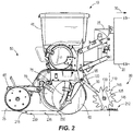
- each planting unit 50 includes a furrow opener 60, at least one furrow closer 65 positioned rearward the furrow opener 60 in the direction of travel 30, a depth member 70, a dispenser 75 in communication with the holding tank 45, and an adjustable row cleaner assembly 80 positioned forward the furrow opener 60 in the direction of travel 30.
- the furrow opener 60 can be a blade, a wheel, a disc, etc. that is either rotatably or fixedly coupled to the frame 35
- the furrow closer 65 can be a blade, a wheel, a disc, etc. that is either rotatably or fixedly coupled to the frame 35.
- the adjustable row cleaner assembly 80 is constructed in a similar manner such that one adjustable row cleaner assembly 80 is discussed in detail below but is applicable to the other adjustable row cleaner assemblies 80.
- the adjustable row cleaner assembly 80 includes a bracket 85 having a first linkage 90 pivotably coupled to the frame 35 about a bracket axis 95.
- a bracket actuator 100 e.g., a hydraulic cylinder; FIG. 2
- the bracket 85 can be fixedly coupled to the frame 35 such that the bracket actuator 100 can be omitted.
- the illustrated bracket 85 also includes a second linkage 105 pivotably coupled to the first linkage 90 about a vertical pivot axis 110, which is substantially transverse to the surface 25, and a third linkage 115 that is also pivotably coupled to the first linkage 90 about the vertical pivot axis 110.
- a linkage actuator 120 e.g., a hydraulic cylinder
- actuation of the linkage actuator 120 moves the second and third linkages 105, 115 an equal amount about the vertical pivot axis 110.
- an angle between the second linkage 105 and the direction of travel 30 is substantially the same as an angle between the third linkage 115 and the direction of travel 30 (in the reference frame of FIG. 3 ).
- the linkage actuator 120 can move the second linkage 105 about the vertical pivot axis 110 a different amount than the third linkage 115.
- the illustrated adjustable row cleaner assembly 80 also includes a first debris cleaner 125 rotatably coupled to the second linkage 105 about a first rotational axis 130 and a second debris cleaner 135 rotatably coupled to the third linkage 115 about a second rotational axis 140.
- the first and second debris cleaners 125, 135 each include teeth 145 operable to contact the surface 25 ( FIG. 2 ).
- the illustrated first and second debris cleaners 125, 135 are substantially planar wheels with the first and second rotational axes 130, 140 oriented parallel to the surface 25.
- first and second debris cleaners 125, 135 can be tilted such that the first and second rotational axes 130, 140 can be obliquely angled relative to the surface 25.
- first and/or second debris cleaners 125, 135 can be fixedly coupled to the bracket 85.
- the first debris cleaner 125 includes a leading edge 150 and a trailing edge 155 in the direction of travel 30.
- the leading edge 150 is a distal forward point on a perimeter of the first debris cleaner 125 in the direction of travel 30, and the trailing edge 155 is a distal rearward point on the perimeter of the first debris cleaner 125 in the direction of travel 30.
- the second debris cleaner 135 includes a leading edge 160 and a trailing edge 165 in the direction of travel 30.
- the leading edge 160 is a distal forward point on a perimeter of the second debris cleaner 135 in the direction of travel 30, and the trailing edge 165 is a distal rearward point on the perimeter of the second debris cleaner 135 in the direction of travel 30.
- the first debris cleaner 125 and the second debris cleaner 135 are positionable relative to the first linkage 90 in at least two positions.
- a first position of the debris cleaners 125, 135 illustrated in solid lines in FIG. 3
- a first distance 170 measured parallel to the direction of travel 30 is defined between the leading edge 150 and the trailing edge 155 of the first debris cleaner 125
- a second distance 175 measured parallel to the direction of travel 30 is defined between the leading edge 160 and the trailing edge 165 of the second debris cleaner 135.
- the linkage actuator 120 is configured to move the first and second debris cleaners 125, 135 the same amount about the vertical pivot axis 110, the first distance 170 is substantially the same as the second distance 175.
- a first angle 178 between the first and second debris cleaners 125, 135 when in the first position can be between about 60 degrees and about 50 degrees. In other embodiments, the first angle 178 can be greater than about 45 degrees but less than about 70 degrees.
- a third distance 180 measured parallel to the direction of travel 30 is defined between the leading edge 150 and the trailing edge 155 of the first debris cleaner 125
- a fourth distance 185 measured parallel to the direction of travel 30 is defined between the leading edge 160 and the trailing edge 165 of the second debris cleaner 135.
- the linkage actuator 120 is configured to move the first and second debris cleaners 125, 135 the same amount about the vertical pivot axis 110
- the third distance 180 is substantially the same as the fourth distance 185.
- the third and fourth distances 180, 185 are greater than the first and second distances 170, 175.
- a second angle 188 between the first and second debris cleaners 125, 135 when in the second position can be between about 40 degrees and about 30 degrees. In other embodiments, the second angle 188 can be greater than about 20 degrees but less than about 45 degrees.
- a fifth distance 190 measured in one of two lateral directions 195 perpendicular to the direction of travel 30 is defined between the trailing edges 155, 165 of the first and second debris cleaners 125, 135.
- a sixth distance 200 measured in one of the two lateral directions 195 is defined between the trailing edges 155, 165 of the first and second debris cleaners 125, 135.
- the fifth distance 190 is greater than the sixth distance 200.
- the tractor 15 pulls the planter 10 across the surface 25 at a particular velocity.
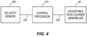
- the velocity of the tractor 15/planter 10 is measured by a velocity sensor 205 (e.g., a global positioning system or the like), which is in communication with a control processor 210 ( FIG. 4 ).
- the tractor 15 or the planter 10 can include the velocity sensor 205, and the tractor 15 or the planter 10 can include the control processor 210.
- the control processor 210 is also in communication with each of the adjustable row cleaner assemblies 80.
- control processor 210 is in communication with the bracket actuator 100 of each assembly 80 to control pivoting movement of the brackets 85 about their bracket axis 95 and is also in communication with the linkage actuator 120 of each assembly 80 to control movement of the first and second debris cleaners 125, 135 about their vertical pivot axis 110.
- the adjustable row cleaner assembly 80 As all of the adjustable row cleaner assemblies 80 operate in a similar manner, only operation of one adjustable row cleaner assembly 80 is discussed below.
- the adjustable row cleaner assembly 80 As the tractor 15 pulls the planter 10 across the surface 25, the adjustable row cleaner assembly 80 is positioned vertically by the bracket actuator 100 such that the teeth 145 of the first and second debris cleaners 125, 135 contact the surface 25. Such contact with the surface 25 moves the first and second debris cleaners 125, 135 about their respective rotational axes 130, 140 as the planter 10 moves along the surface 25. Accordingly, the first and second debris cleaners 125, 135 push debris 212 (e.g., residue vegetation on the surface 25) in the lateral directions 195.
- debris 212 e.g., residue vegetation on the surface 25
- each first and second debris cleaner 125, 135 moves the debris 212 in one of the two lateral directions 195 to inhibit the debris 212 from entering the furrow 215.
- the control processor 210 controls the position of the debris cleaners 125, 135 dependent upon the velocity of the planter 10/tractor 15 to inhibit the debris cleaners 125, 135 from pushing surface debris 212 too far into an adjacent furrow 215. Stated another way, the control processor 210 receives a first signal 220 ( FIG.
- the control processor 210 actuates the linkage actuator 120 to position the debris cleaners 125, 135 in the first position (illustrated in solid lines in FIG. 3 ).
- the debris cleaners 125, 135 are positioned wider (e.g., the fifth distance 190 compared to the sixth distance 200) to push the surface debris 212 a sufficient amount in the lateral directions 195 (e.g., to position the surface debris 212 between adjacent furrows 215).
- the control processor 210 actuates the linkage actuator 120 to move the debris cleaners 125, 135 toward the second position (illustrated in broken lines in FIG. 3 ).
- the debris cleaners 125, 135 are positioned narrower (e.g., the sixth distance 200 compared to the fifth distance 190) to push the surface debris 212 a sufficient amount in the lateral directions 195 (e.g., between adjacent furrows 215).
- the control processor 210 moves the position of the debris cleaners 125, 135 dependent upon the velocity of the planter 10/tractor 15 to ensure the surface debris 212 is moved enough in the lateral directions 195 as to not enter the furrow 215 formed by the corresponding furrow opener 60 and to also ensure the surface debris 212 isn't moved too far in the lateral directions 195 as to enter an adjacent furrow 215.
- control processor 210 is operable to change a downward force of the debris cleaners 125, 135 against the surface 25 dependent upon a velocity of the planter 10/tractor 15. Stated another way, the control processor 210 receives the first signal 220 from the velocity sensor 205 and sends the second signal 225 to the adjustable row cleaner assembly 80 that represents a downward force of the debris cleaners 125, 135 against the surface 25 based on the velocity of the planter 10/tractor 15. For example, the control processor 210 controls the bracket actuator 100 to move the debris cleaners 125, 135 away from the surface 25 as the velocity of the planter 10 decreases to decrease a force of the debris cleaners 125, 135 acting on the surface 25.
- control processor 210 controls the bracket actuator 100 to move the debris cleaners 125, 135 toward the surface 25 as the velocity of the planter 10 increases to increase a force of the debris cleaners 125, 135 acting on the surface 25. Accordingly, the debris cleaners 125, 135 push the surface debris 212 a desired amount in the lateral directions 195 dependent upon a velocity of the planter 10.
- the control processor 210 can also control the downward force of the debris cleaners 125, 135 on the surface 25 dependent upon a quantity of surface debris 212 on the surface 25.
- the control processor 210 controls the bracket actuator 100 to move the debris cleaners 125, 135 toward the surface 25 to provide more force of the debris cleaners 125, 135 against the surface 25 to ensure the surface debris 212 is pushed a sufficient amount in the lateral directions 195.
- a sensor can be in communication with the control processor 210 operable to measure a quantity of surface debris 212 on the surface 25.
- the control processor 210 receives a first signal from the sensor that represents a quantity of surface debris 212 and sends a second signal to the adjustable row cleaner assembly 80 that represents a downward force of the debris cleaners 125, 135 against the surface 25 based on the quantity of the surface debris 212.
- control processor 210 can receive two signals one of which represents a velocity of the planter 10 and the other a quantity of surface debris 212 and sends a third signal to the adjustable row cleaner assembly 80 that represents a lateral position of the residue cleaners 125, 135 and/or a downward force of the residue cleaners 125, 135.
- the dispenser 75 of the planter 10 incrementally drops seeds 230 from the holding tank 45 within the furrow 215 as the planter 10 moves across the surface 25.
- the furrow 215 defines a channel within the surface 25 having a longitudinal axis, which is parallel to the direction of travel 30, and a width perpendicular to the longitudinal axis (e.g., parallel to the lateral directions 195) of the furrow 215.
- the depth member 70 is also in communication with the control processor 210 and is operable to measure a depth of the furrow 215 such that the planter 10 can adjust the depth of the furrow 215.
- the illustrated furrow closer 65 covers the seeds 230 within the furrow 215 so that the seeds 230 are encapsulated below the surface 25 and the seeds 230 can begin to grow.
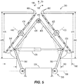
- FIG. 5 illustrates an adjustable row cleaner assembly 380 according to another embodiment.
- the adjustable row cleaner assembly 380 is similar to the adjustable row cleaner assembly 80; therefore, similar components are designated with similar references numbers plus 300. At least some differences and/or at least some similarities between the adjustable row cleaner assemblies 80, 380 will be discussed in detail below. In addition, components or features described with respect to the adjustable row cleaner assembly 380 are equally applicable to the adjustable row cleaner assembly 80 described above.
- the illustrated adjustable row cleaner assembly 380 includes a bracket 385 having a pair of first linkages 390 pivotably coupled to a frame 335 of the planter 10 about a bracket axis 395 and a pair of second linkages 405 pivotably coupled together about a vertical pivot axis 410. Each second linkage 405 is also pivotably coupled to one of the first linkages 390 about a joint 535.
- a linkage actuator 420 is coupled to the two joints 535 and is operable to move the joints 535 relative to each other in the lateral directions 195.
- the linkage actuator 420 can be coupled to the pair of first linkages 390, the pair of second linkages 405, or one of the first linkages 390 and one of the second linkages 405 to move the joints 535 relative to each other.
- the illustrated linkage actuator 420 is in communication with the control processor 210.
- a first debris cleaner 425 is rotatably coupled to one of the second linkages 405 about a first rotational axis 430, and a second debris cleaner 435 is rotatably coupled to the other second linkage 405 about a second rotational axis 440.
- the first debris cleaner 425 includes a leading edge 450 and a trailing edge 455 in the direction of travel 30.
- the second debris cleaner 435 includes a leading edge 460 and a trailing edge 465 in the direction of travel 30.
- a first distance 470 is defined between the leading edge 450 and the trailing edge 455 of the first debris cleaner 425, and a second distance 475 which is substantially the same as the first distance 470 is defined between the leading edge 460 and the trailing edge 465 of the second debris cleaner 435.
- a second position of the debris cleaners 425, 435 illustrated in broken lines in FIG.
- a third distance 480 is defined between the leading edge 450 and the trailing edge 455 of the first debris cleaner 425, and a fourth distance 485 which is substantially the same as the third distance 480-is defined between the leading edge 460 and the trailing edge 465 of the second debris cleaner 435.
- a fifth distance 490 is defined between the trailing edges 455, 465 of the first and second debris cleaners 425, 435, which is greater than a sixth distance 500 defined between the trailing edges 455, 465 of the first and second debris cleaners 425, 435 when the first and second debris cleaners 425, 435 are in the second position (illustrated in broken lines in FIG. 5 ).
- FIG. 6 illustrates an adjustable row cleaner assembly 680 according to another embodiment.
- the adjustable row cleaner assembly 680 is similar to the adjustable row cleaner assembly 80; therefore, similar components are designated with similar references numbers plus 600. At least some differences and/or at least some similarities between the adjustable row cleaner assemblies 80, 680 will be discussed in detail below. In addition, components or features described with respect to the adjustable row cleaner assembly 680 are equally applicable to the adjustable row cleaner assemblies 80, 380 described above.
- the illustrated adjustable row cleaner assembly 680 includes a bracket 685 having a linkage 690 pivotably coupled to a frame 635 of the planter 10 about a bracket axis 695.
- the bracket 685 also includes a first hub 840 pivotably coupled to the linkage 690 about a first vertical pivot axis 710a, and a second hub 845 pivotably coupled to the linkage 690 about a second vertical pivot axis 710b.
- a first linkage actuator 720a is coupled to the linkage 690 and the first hub 840
- a second linkage actuator 720b is coupled to the linkage 690 and the second hub 845. Both the first and second linkage actuators 720a, 720b are in communication with the control processor 210 and are operable to move the corresponding hub 840, 845 about their vertical pivot axis 710a, 710b.
- a first debris cleaner 725 is rotatably coupled to the first hub 840 about a first rotational axis 730, and a second debris cleaner 735 is rotatably coupled to the second hub 845 about a second rotational axis 740.
- the first debris cleaner 725 includes a leading edge 750 and a trailing edge 755 in the direction of travel 30.
- the second debris cleaner 735 includes a leading edge 760 and a trailing edge 765 in the direction of travel 30.
- a first distance 770 is defined between the leading edge 750 and the trailing edge 755 of the first debris cleaner 725, and a second distance 775 which is substantially the same as the first distance 770 is defined between the leading edge 760 and the trailing edge 765 of the second debris cleaner 735.
- a second position of the debris cleaners 725, 735 illustrated in broken lines in FIG.
- a third distance 780 is defined between the leading edge 750 and the trailing edge 755 of the first debris cleaner 725, and a fourth distance 785 which is substantially the same as the third distance 780 is defined between the leading edge 760 and the trailing edge 765 of the second debris cleaner 735.
- a fifth distance 790 is defined between the trailing edges 755, 765 of the first and second debris cleaners 725, 735, which is greater than a sixth distance 800 defined between the trailing edges 755, 765 of the first and second debris cleaners 725, 735 when the first and second debris cleaners 725, 735 are in the second position (illustrated in broken lines in FIG. 6 ).
- FIG. 7 illustrates an adjustable row cleaner assembly 980 according to another embodiment.
- the adjustable row cleaner assembly 980 is similar to the adjustable row cleaner assembly 80; therefore, similar components are designated with similar references numbers plus 900. At least some differences and/or at least some similarities between the adjustable row cleaner assemblies 80, 980 will be discussed in detail below. In addition, components or features described with respect to the adjustable row cleaner assembly 980 are equally applicable to the adjustable row cleaner assemblies 80, 380, 680 described above.
- the illustrated adjustable row cleaner assembly 980 includes a bracket 985 having first and second linkages 990, 1005 pivotably coupled to a frame 935 of the planter 10 about a bracket axis 995.
- the bracket 985 also includes a first hub 1140 pivotably coupled to the first linkage 990 about a first vertical pivot axis 1010a, and a second hub 1145 pivotably coupled to the second linkage 1005 about a second vertical pivot axis 1010b.
- a first linkage actuator 1020a is coupled to the frame 935 and the first hub 1140
- a second linkage actuator 1020b is coupled to the frame 935 and the second hub 1145. Both the first and second linkage actuators 1020a, 1020b are in communication with the control processor 210 and are operable to move the corresponding hub 1140, 1145 about their vertical pivot axis 1010a, 1010b.
- a first debris cleaner 1025 is rotatably coupled to the first hub 1140 about a first rotational axis 1030, and a second debris cleaner 1035 is rotatably coupled to the second hub 1145 about a second rotational axis 1040.
- the first debris cleaner 1025 includes a leading edge 1050 and a trailing edge 1055 in the direction of travel 30.
- the second debris cleaner 1035 includes a leading edge 1060 and a trailing edge 1065 in the direction of travel 30.
- a first distance 1070 is defined between the leading edge 1050 and the trailing edge 1055 of the first debris cleaner 1025, and a second distance 1075 which is substantially the same as the first distance 1070 is defined between the leading edge 1060 and the trailing edge 1065 of the second debris cleaner 1035.
- a second position of the debris cleaners 1025, 1035 illustrated in broken lines in FIG.
- a third distance 1080 is defined between the leading edge 1050 and the trailing edge 1055 of the first debris cleaner 1025, and a fourth distance 1085-which is substantially the same as the third distance 1080-is defined between the leading edge 1060 and the trailing edge 1065 of the second debris cleaner 1035.
- a fifth distance 1090 is defined between the trailing edges 1055, 1065 of the first and second debris cleaners 1025, 1035, which is greater than a sixth distance 1100 defined between the trailing edges 1055, 1065 of the first and second debris cleaners 1025, 1035 when the first and second debris cleaners 1025, 1035 are in the second position (illustrated in broken lines in FIG. 7 ).
Landscapes
- Life Sciences & Earth Sciences (AREA)
- Soil Sciences (AREA)
- Environmental Sciences (AREA)
- Engineering & Computer Science (AREA)
- Mechanical Engineering (AREA)
- Soil Working Implements (AREA)
- Agricultural Machines (AREA)
- Guiding Agricultural Machines (AREA)
- Agricultural Chemicals And Associated Chemicals (AREA)
- Cleaning Of Streets, Tracks, Or Beaches (AREA)
- Sowing (AREA)
Abstract
Description
- The present disclosure relates to an agricultural planter, and more particularly to row cleaners of the agricultural planter that inhibit debris from entering furrows formed by the agricultural planter.
- In one aspect, an agricultural planter is operable in a travel direction and a travel velocity and configured to dispense seeds into a furrow formed within an agricultural surface. An adjustment assembly is for the agricultural planter and includes a bracket configured to be coupled to a frame of the agricultural planter and a debris cleaner coupled to the bracket. The debris cleaner is configured such that during operation of the agricultural planter the debris cleaner has, relative to the travel direction, a leading edge and a trailing edge. The debris cleaner is movable such that a distance between the leading and trailing edges in the travel direction is adjustable.
- In another aspect, an agricultural planter is operable in a travel direction and configured to dispense seeds into a furrow formed within an agricultural surface. The furrow has a longitudinal axis and a width in a lateral direction perpendicular to the longitudinal axis. An adjustment assembly is for the agricultural planter and includes a bracket configured to be coupled to a frame of the agricultural planter, a first debris cleaner coupled to the bracket and configured such that during operation of the agricultural planter the first debris cleaner has, relative to the travel direction, a trailing edge, and a second debris cleaner coupled to the bracket and configured such that during operation of the agricultural planter the second debris cleaner has, relative to the travel direction, a trailing edge. During operation a distance between the trailing edges of the first and second debris cleaners in the lateral direction is adjustable.
- In yet another aspect, an agricultural planter is operable in a travel direction and configured to dispense seeds into a furrow formed within an agricultural surface. An adjustment assembly is for the agricultural planter and includes a bracket configured to be coupled to a frame of the agricultural planter and a debris cleaner coupled to the bracket. The debris cleaner is configured to inhibit debris from entering the furrow. The adjustment assembly also includes a control processor configured to receive a first signal representing a first velocity of the agricultural planter relative to the agricultural surface, send a second signal to actuate movement of the debris cleaner into a first position based on the first signal, receive a third signal representing a second velocity of the agricultural planter relative to the agricultural surface, and send a fourth signal to actuate movement of the debris cleaner into a second position based on the third signal.
- Other aspects of the disclosure will become apparent by consideration of the detailed description and accompanying drawings.
-
-
FIG. 1 is a perspective view of an agricultural planter coupled to a vehicle. -
FIG. 2 is a side view of the agricultural planter ofFIG. 1 . -
FIG. 3 is a top view of an adjustable row cleaner assembly of the agricultural planter ofFIG. 2 according to an embodiment of the disclosure. -
FIG. 4 illustrates a control processor in communication with the adjustable row cleaner assembly. -
FIG. 5 is a top view of an adjustable row cleaner assembly according to another embodiment of the disclosure. -
FIG. 6 is a top view of an adjustable row cleaner assembly according to another embodiment of the disclosure. -
FIG. 7 is a top view of an adjustable row cleaner assembly according to another embodiment of the disclosure. - Before any embodiments of the disclosure are explained in detail, it is to be understood that the disclosure is not limited in its application to the details of construction and the arrangement of components set forth in the following description or illustrated in the following drawings. The disclosure is capable of other embodiments and of being practiced or of being carried out in various ways. Also, it is to be understood that the phraseology and terminology used herein is for the purpose of description and should not be regarded as limiting. Terms of degree, such as "substantially," "about," "approximately," etc. are understood by those of ordinary skill to refer to reasonable ranges outside of the given value, for example, general tolerances associated with manufacturing, assembly, and use of the described embodiments.
-
FIG. 1 illustrates anagricultural planter 10 coupled to a vehicle (e.g., a tractor 15). In particular, the illustratedplanter 10 is selectively coupled to ahitch 20 of thetractor 15 for thetractor 15 to pull theplanter 10 across an agricultural surface 25 (FIG. 2 ) in a direction oftravel 30. The illustratedplanter 10 includes aframe 35,wheels 40 coupled to theframe 35 to support theplanter 10 above thesurface 25, aholding tank 45 configured to support agricultural seeds (e.g., corn seeds, bean seeds, etc.), and a plurality ofplanting units 50 coupled to theframe 35 with eachplanting unit 50 equally spaced along alongitudinal axis 55 of theframe 35 relative to anadjacent planting unit 50. Eachplanting unit 50 is also in communication with theholding tank 45. As best shown inFIG. 2 , eachplanting unit 50 includes afurrow opener 60, at least one furrow closer 65 positioned rearward thefurrow opener 60 in the direction oftravel 30, adepth member 70, adispenser 75 in communication with theholding tank 45, and an adjustablerow cleaner assembly 80 positioned forward thefurrow opener 60 in the direction oftravel 30. In some embodiments, thefurrow opener 60 can be a blade, a wheel, a disc, etc. that is either rotatably or fixedly coupled to theframe 35, and/or the furrow closer 65 can be a blade, a wheel, a disc, etc. that is either rotatably or fixedly coupled to theframe 35. - Each adjustable
row cleaner assembly 80 is constructed in a similar manner such that one adjustablerow cleaner assembly 80 is discussed in detail below but is applicable to the other adjustablerow cleaner assemblies 80. With reference toFIG. 3 , the adjustablerow cleaner assembly 80 includes abracket 85 having afirst linkage 90 pivotably coupled to theframe 35 about abracket axis 95. A bracket actuator 100 (e.g., a hydraulic cylinder;FIG. 2 ) is coupled to thefirst linkage 90 and theframe 35 and operable to pivot thebracket 85 about thebracket axis 95. In other embodiments, thebracket 85 can be fixedly coupled to theframe 35 such that thebracket actuator 100 can be omitted. With continued reference toFIG. 3 , the illustratedbracket 85 also includes asecond linkage 105 pivotably coupled to thefirst linkage 90 about avertical pivot axis 110, which is substantially transverse to thesurface 25, and athird linkage 115 that is also pivotably coupled to thefirst linkage 90 about thevertical pivot axis 110. A linkage actuator 120 (e.g., a hydraulic cylinder) is coupled to distal ends-relative to the vertical pivot axis 110-of the second andthird linkages vertical pivot axis 110. In the illustrated embodiment, actuation of thelinkage actuator 120 moves the second andthird linkages vertical pivot axis 110. For example, an angle between thesecond linkage 105 and the direction oftravel 30 is substantially the same as an angle between thethird linkage 115 and the direction of travel 30 (in the reference frame ofFIG. 3 ). In other embodiments, thelinkage actuator 120 can move thesecond linkage 105 about the vertical pivot axis 110 a different amount than thethird linkage 115. - The illustrated adjustable
row cleaner assembly 80 also includes afirst debris cleaner 125 rotatably coupled to thesecond linkage 105 about a firstrotational axis 130 and asecond debris cleaner 135 rotatably coupled to thethird linkage 115 about a secondrotational axis 140. In the illustrated embodiment, the first andsecond debris cleaners teeth 145 operable to contact the surface 25 (FIG. 2 ). The illustrated first andsecond debris cleaners rotational axes surface 25. In other embodiments, the first andsecond debris cleaners rotational axes surface 25. In further embodiments, the first and/orsecond debris cleaners bracket 85. - With continued reference to
FIG. 3 , thefirst debris cleaner 125 includes a leadingedge 150 and atrailing edge 155 in the direction oftravel 30. In particular, the leadingedge 150 is a distal forward point on a perimeter of thefirst debris cleaner 125 in the direction oftravel 30, and thetrailing edge 155 is a distal rearward point on the perimeter of thefirst debris cleaner 125 in the direction oftravel 30. Likewise, thesecond debris cleaner 135 includes a leadingedge 160 and atrailing edge 165 in the direction oftravel 30. In particular, the leadingedge 160 is a distal forward point on a perimeter of thesecond debris cleaner 135 in the direction oftravel 30, and thetrailing edge 165 is a distal rearward point on the perimeter of thesecond debris cleaner 135 in the direction oftravel 30. By actuating thelinkage actuator 120, thefirst debris cleaner 125 and thesecond debris cleaner 135 are positionable relative to thefirst linkage 90 in at least two positions. In a first position of thedebris cleaners 125, 135 (illustrated in solid lines inFIG. 3 ), afirst distance 170 measured parallel to the direction oftravel 30 is defined between the leadingedge 150 and thetrailing edge 155 of thefirst debris cleaner 125, and asecond distance 175 measured parallel to the direction oftravel 30 is defined between the leadingedge 160 and thetrailing edge 165 of thesecond debris cleaner 135. As thelinkage actuator 120 is configured to move the first andsecond debris cleaners vertical pivot axis 110, thefirst distance 170 is substantially the same as thesecond distance 175. In the illustrated embodiment, afirst angle 178 between the first andsecond debris cleaners first angle 178 can be greater than about 45 degrees but less than about 70 degrees. - In a second position of the
debris cleaners 125, 135 (illustrated in broken lines inFIG. 3 ), athird distance 180 measured parallel to the direction oftravel 30 is defined between the leadingedge 150 and thetrailing edge 155 of thefirst debris cleaner 125, and afourth distance 185 measured parallel to the direction oftravel 30 is defined between the leadingedge 160 and thetrailing edge 165 of thesecond debris cleaner 135. Again, as thelinkage actuator 120 is configured to move the first andsecond debris cleaners vertical pivot axis 110, thethird distance 180 is substantially the same as thefourth distance 185. In addition, the third andfourth distances second distances second angle 188 between the first andsecond debris cleaners second angle 188 can be greater than about 20 degrees but less than about 45 degrees. - Also, when the first and
second debris cleaners FIG. 3 ), afifth distance 190 measured in one of twolateral directions 195 perpendicular to the direction oftravel 30 is defined between thetrailing edges second debris cleaners second debris cleaners FIG. 3 ), asixth distance 200 measured in one of the twolateral directions 195 is defined between thetrailing edges second debris cleaners fifth distance 190 is greater than thesixth distance 200. - During operation, the
tractor 15 pulls theplanter 10 across thesurface 25 at a particular velocity. The velocity of thetractor 15/planter 10 is measured by a velocity sensor 205 (e.g., a global positioning system or the like), which is in communication with a control processor 210 (FIG. 4 ). In some embodiments, thetractor 15 or theplanter 10 can include thevelocity sensor 205, and thetractor 15 or theplanter 10 can include thecontrol processor 210. With continued reference toFIG. 4 , thecontrol processor 210 is also in communication with each of the adjustable rowcleaner assemblies 80. In particular, thecontrol processor 210 is in communication with thebracket actuator 100 of eachassembly 80 to control pivoting movement of thebrackets 85 about theirbracket axis 95 and is also in communication with thelinkage actuator 120 of eachassembly 80 to control movement of the first andsecond debris cleaners vertical pivot axis 110. - As all of the adjustable row
cleaner assemblies 80 operate in a similar manner, only operation of one adjustable rowcleaner assembly 80 is discussed below. With reference back toFIG. 2 , as thetractor 15 pulls theplanter 10 across thesurface 25, the adjustable rowcleaner assembly 80 is positioned vertically by thebracket actuator 100 such that theteeth 145 of the first andsecond debris cleaners surface 25. Such contact with thesurface 25 moves the first andsecond debris cleaners rotational axes planter 10 moves along thesurface 25. Accordingly, the first andsecond debris cleaners lateral directions 195. This allows a clean surface for thefurrow opener 60 to dig into thesurface 25 to form a furrow 215 (FIG. 2 ). Stated another way, each first andsecond debris cleaner debris 212 in one of the twolateral directions 195 to inhibit thedebris 212 from entering thefurrow 215. - However, as the
planter 10 increases in velocity across thesurface 25, thedebris cleaners cleaner assembly 80 could push thesurface debris 212 too far in thelateral directions 195 potentially causing somesurface debris 212 to enter afurrow 215 formed by an adjacent adjustable rowcleaner assembly 80. Therefore, in the illustrated embodiment, thecontrol processor 210 controls the position of thedebris cleaners planter 10/tractor 15 to inhibit thedebris cleaners surface debris 212 too far into anadjacent furrow 215. Stated another way, thecontrol processor 210 receives a first signal 220 (FIG. 4 ) from thevelocity sensor 205 that represents a velocity of theplanter 10/tractor 15 and sends asecond signal 225 to the adjustable rowcleaner assembly 80 that represents a position of thedebris cleaners planter 10/tractor 15. For example, as theplanter 10 travels at a relatively slow velocity across thesurface 25, thecontrol processor 210 actuates thelinkage actuator 120 to position thedebris cleaners FIG. 3 ). As such, thedebris cleaners fifth distance 190 compared to the sixth distance 200) to push the surface debris 212 a sufficient amount in the lateral directions 195 (e.g., to position thesurface debris 212 between adjacent furrows 215). In contrast, as the velocity of theplanter 10 increases across thesurface 25, thecontrol processor 210 actuates thelinkage actuator 120 to move thedebris cleaners FIG. 3 ). As such, thedebris cleaners sixth distance 200 compared to the fifth distance 190) to push the surface debris 212 a sufficient amount in the lateral directions 195 (e.g., between adjacent furrows 215). Accordingly, thecontrol processor 210 moves the position of thedebris cleaners planter 10/tractor 15 to ensure thesurface debris 212 is moved enough in thelateral directions 195 as to not enter thefurrow 215 formed by the correspondingfurrow opener 60 and to also ensure thesurface debris 212 isn't moved too far in thelateral directions 195 as to enter anadjacent furrow 215. - In addition, the
control processor 210 is operable to change a downward force of thedebris cleaners surface 25 dependent upon a velocity of theplanter 10/tractor 15. Stated another way, thecontrol processor 210 receives thefirst signal 220 from thevelocity sensor 205 and sends thesecond signal 225 to the adjustable rowcleaner assembly 80 that represents a downward force of thedebris cleaners surface 25 based on the velocity of theplanter 10/tractor 15. For example, thecontrol processor 210 controls thebracket actuator 100 to move thedebris cleaners surface 25 as the velocity of theplanter 10 decreases to decrease a force of thedebris cleaners surface 25. In contrast, thecontrol processor 210 controls thebracket actuator 100 to move thedebris cleaners surface 25 as the velocity of theplanter 10 increases to increase a force of thedebris cleaners surface 25. Accordingly, thedebris cleaners lateral directions 195 dependent upon a velocity of theplanter 10. Thecontrol processor 210 can also control the downward force of thedebris cleaners surface 25 dependent upon a quantity ofsurface debris 212 on thesurface 25. For example, as the quantity ofsurface debris 212 increases, thecontrol processor 210 controls thebracket actuator 100 to move thedebris cleaners surface 25 to provide more force of thedebris cleaners surface 25 to ensure thesurface debris 212 is pushed a sufficient amount in thelateral directions 195. Accordingly, in some embodiments, a sensor can be in communication with thecontrol processor 210 operable to measure a quantity ofsurface debris 212 on thesurface 25. Stated another way, thecontrol processor 210 receives a first signal from the sensor that represents a quantity ofsurface debris 212 and sends a second signal to the adjustable rowcleaner assembly 80 that represents a downward force of thedebris cleaners surface 25 based on the quantity of thesurface debris 212. In further embodiments, thecontrol processor 210 can receive two signals one of which represents a velocity of theplanter 10 and the other a quantity ofsurface debris 212 and sends a third signal to the adjustable rowcleaner assembly 80 that represents a lateral position of theresidue cleaners residue cleaners - Once the
furrow 215 is formed by thefurrow opener 60, thedispenser 75 of theplanter 10 incrementally dropsseeds 230 from the holdingtank 45 within thefurrow 215 as theplanter 10 moves across thesurface 25. In particular, thefurrow 215 defines a channel within thesurface 25 having a longitudinal axis, which is parallel to the direction oftravel 30, and a width perpendicular to the longitudinal axis (e.g., parallel to the lateral directions 195) of thefurrow 215. Thedepth member 70 is also in communication with thecontrol processor 210 and is operable to measure a depth of thefurrow 215 such that theplanter 10 can adjust the depth of thefurrow 215. Furthermore, after theseeds 230 have been dispensed into thefurrow 215, the illustrated furrow closer 65 then covers theseeds 230 within thefurrow 215 so that theseeds 230 are encapsulated below thesurface 25 and theseeds 230 can begin to grow. -
FIG. 5 illustrates an adjustable rowcleaner assembly 380 according to another embodiment. The adjustable rowcleaner assembly 380 is similar to the adjustable rowcleaner assembly 80; therefore, similar components are designated with similar references numbers plus 300. At least some differences and/or at least some similarities between the adjustable rowcleaner assemblies cleaner assembly 380 are equally applicable to the adjustable rowcleaner assembly 80 described above. - The illustrated adjustable row
cleaner assembly 380 includes abracket 385 having a pair offirst linkages 390 pivotably coupled to aframe 335 of theplanter 10 about abracket axis 395 and a pair ofsecond linkages 405 pivotably coupled together about avertical pivot axis 410. Eachsecond linkage 405 is also pivotably coupled to one of thefirst linkages 390 about a joint 535. Alinkage actuator 420 is coupled to the twojoints 535 and is operable to move thejoints 535 relative to each other in thelateral directions 195. In other embodiments, thelinkage actuator 420 can be coupled to the pair offirst linkages 390, the pair ofsecond linkages 405, or one of thefirst linkages 390 and one of thesecond linkages 405 to move thejoints 535 relative to each other. The illustratedlinkage actuator 420 is in communication with thecontrol processor 210. - A
first debris cleaner 425 is rotatably coupled to one of thesecond linkages 405 about a firstrotational axis 430, and asecond debris cleaner 435 is rotatably coupled to the othersecond linkage 405 about a secondrotational axis 440. Thefirst debris cleaner 425 includes aleading edge 450 and a trailingedge 455 in the direction oftravel 30. Likewise, thesecond debris cleaner 435 includes aleading edge 460 and a trailingedge 465 in the direction oftravel 30. - In a first position of the
debris cleaners 425, 435 (illustrated in solid lines inFIG. 5 ), afirst distance 470 is defined between theleading edge 450 and the trailingedge 455 of thefirst debris cleaner 425, and asecond distance 475 which is substantially the same as thefirst distance 470 is defined between theleading edge 460 and the trailingedge 465 of thesecond debris cleaner 435. In a second position of thedebris cleaners 425, 435 (illustrated in broken lines inFIG. 5 ), athird distance 480 is defined between theleading edge 450 and the trailingedge 455 of thefirst debris cleaner 425, and afourth distance 485 which is substantially the same as the third distance 480-is defined between theleading edge 460 and the trailingedge 465 of thesecond debris cleaner 435. - In addition, when the first and
second debris cleaners FIG. 5 ), afifth distance 490 is defined between the trailingedges second debris cleaners sixth distance 500 defined between the trailingedges second debris cleaners second debris cleaners FIG. 5 ). -
FIG. 6 illustrates an adjustable rowcleaner assembly 680 according to another embodiment. The adjustable rowcleaner assembly 680 is similar to the adjustable rowcleaner assembly 80; therefore, similar components are designated with similar references numbers plus 600. At least some differences and/or at least some similarities between the adjustable rowcleaner assemblies cleaner assembly 680 are equally applicable to the adjustable rowcleaner assemblies - The illustrated adjustable row
cleaner assembly 680 includes abracket 685 having alinkage 690 pivotably coupled to aframe 635 of theplanter 10 about abracket axis 695. Thebracket 685 also includes afirst hub 840 pivotably coupled to thelinkage 690 about a firstvertical pivot axis 710a, and asecond hub 845 pivotably coupled to thelinkage 690 about a secondvertical pivot axis 710b. Afirst linkage actuator 720a is coupled to thelinkage 690 and thefirst hub 840, and asecond linkage actuator 720b is coupled to thelinkage 690 and thesecond hub 845. Both the first andsecond linkage actuators control processor 210 and are operable to move thecorresponding hub vertical pivot axis - A
first debris cleaner 725 is rotatably coupled to thefirst hub 840 about a firstrotational axis 730, and asecond debris cleaner 735 is rotatably coupled to thesecond hub 845 about a secondrotational axis 740. Thefirst debris cleaner 725 includes aleading edge 750 and a trailingedge 755 in the direction oftravel 30. Likewise, thesecond debris cleaner 735 includes aleading edge 760 and a trailingedge 765 in the direction oftravel 30. - In a first position of the
debris cleaners 725, 735 (illustrated in solid lines inFIG. 6 ), afirst distance 770 is defined between theleading edge 750 and the trailingedge 755 of thefirst debris cleaner 725, and asecond distance 775 which is substantially the same as thefirst distance 770 is defined between theleading edge 760 and the trailingedge 765 of thesecond debris cleaner 735. In a second position of thedebris cleaners 725, 735 (illustrated in broken lines inFIG. 6 ), a third distance 780 is defined between theleading edge 750 and the trailingedge 755 of thefirst debris cleaner 725, and afourth distance 785 which is substantially the same as the third distance 780 is defined between theleading edge 760 and the trailingedge 765 of thesecond debris cleaner 735. - In addition, when the first and
second debris cleaners FIG. 6 ), afifth distance 790 is defined between the trailingedges second debris cleaners sixth distance 800 defined between the trailingedges second debris cleaners second debris cleaners FIG. 6 ). -
FIG. 7 illustrates an adjustable rowcleaner assembly 980 according to another embodiment. The adjustable rowcleaner assembly 980 is similar to the adjustable rowcleaner assembly 80; therefore, similar components are designated with similar references numbers plus 900. At least some differences and/or at least some similarities between the adjustable rowcleaner assemblies cleaner assembly 980 are equally applicable to the adjustable rowcleaner assemblies - The illustrated adjustable row
cleaner assembly 980 includes abracket 985 having first andsecond linkages frame 935 of theplanter 10 about abracket axis 995. Thebracket 985 also includes afirst hub 1140 pivotably coupled to thefirst linkage 990 about a firstvertical pivot axis 1010a, and asecond hub 1145 pivotably coupled to thesecond linkage 1005 about a secondvertical pivot axis 1010b. Afirst linkage actuator 1020a is coupled to theframe 935 and thefirst hub 1140, and asecond linkage actuator 1020b is coupled to theframe 935 and thesecond hub 1145. Both the first andsecond linkage actuators control processor 210 and are operable to move the correspondinghub vertical pivot axis - A
first debris cleaner 1025 is rotatably coupled to thefirst hub 1140 about a firstrotational axis 1030, and asecond debris cleaner 1035 is rotatably coupled to thesecond hub 1145 about a secondrotational axis 1040. Thefirst debris cleaner 1025 includes aleading edge 1050 and atrailing edge 1055 in the direction oftravel 30. Likewise, thesecond debris cleaner 1035 includes aleading edge 1060 and atrailing edge 1065 in the direction oftravel 30. - In a first position of the
debris cleaners 1025, 1035 (illustrated in solid lines inFIG. 7 ), afirst distance 1070 is defined between theleading edge 1050 and thetrailing edge 1055 of thefirst debris cleaner 1025, and asecond distance 1075 which is substantially the same as thefirst distance 1070 is defined between theleading edge 1060 and thetrailing edge 1065 of thesecond debris cleaner 1035. In a second position of thedebris cleaners 1025, 1035 (illustrated in broken lines inFIG. 7 ), athird distance 1080 is defined between theleading edge 1050 and thetrailing edge 1055 of thefirst debris cleaner 1025, and a fourth distance 1085-which is substantially the same as the third distance 1080-is defined between theleading edge 1060 and thetrailing edge 1065 of thesecond debris cleaner 1035. - In addition, when the first and
second debris cleaners FIG. 7 ), afifth distance 1090 is defined between the trailingedges second debris cleaners sixth distance 1100 defined between the trailingedges second debris cleaners second debris cleaners FIG. 7 ). - Although the disclosure has been described in detail with reference to certain preferred embodiments, variations and modifications exist within the scope and spirit of one or more independent aspects of the disclosure as described. Various features and advantages of the disclosure are set forth in the following claims.
Claims (16)
- An adjustable row cleaner assembly (80, 380, 680, 980) for an agricultural planter (10) operable in a travel direction (30) and a travel velocity and configured to dispense seeds (230) into a furrow (215) formed within an agricultural surface (25), the adjustable row cleaner assembly (80, 380, 680, 980) comprising:a bracket (85, 385, 685, 985) configured to be couplable to a frame (35, 335, 635, 935) of an agricultural planter (10); andat least one debris cleaner (125, 135, 425, 435, 725, 735, 1025, 1035) coupled to the bracket (85, 385, 685, 985), the at least one debris cleaner (125, 135, 425, 435, 725, 735, 1025, 1035) configured such that during operation of the agricultural planter (10) the at least one debris cleaner (125, 135, 425, 435, 725, 735, 1025, 1035) has, relative to the travel direction (30), a leading edge (150, 160, 450, 460, 750, 760, 1050,1060) and a trailing edge (155, 165, 455, 465, 755, 765, 1055,1065);wherein the at least one debris cleaner (125, 135, 425, 435, 725, 735, 1025, 1035) is movable such that a distance (170, 175, 180, 185, 470, 475, 480, 485,770, 775, 780, 785, 1070, 1075, 1080, 1085) between the leading (150, 160, 450, 460, 750, 760, 1050,1060) and trailing edges (155, 165, 455, 465, 755, 765, 1055,1065) in the travel direction (30) is adjustable.
- The adjustable row cleaner assembly (80, 380, 680, 980) of claim 1, wherein the distance (170, 175, 180, 185, 470, 475, 480, 485,770, 775, 780, 785, 1070, 1075, 1080, 1085) between the leading (150, 160, 450, 460, 750, 760, 1050,1060) and trailing (155, 165, 455, 465, 755, 765, 1055,1065) edges in the travel direction (30) is configured to decrease in response to decreasing the travel velocity of the agricultural planter (10) relative to the agricultural surface (25), and wherein the distance (170, 175, 180, 185, 470, 475, 480, 485,770, 775, 780, 785, 1070, 1075, 1080, 1085) between the leading (150, 160, 450, 460, 750, 760, 1050,1060) and trailing (155, 165, 455, 465, 755, 765, 1055,1065) edges in the travel direction (30) is configured to increase in response to increasing the travel velocity of the agricultural planter (10).
- The adjustable row cleaner assembly (80, 380, 680, 980) of claim 1 or 2, wherein the bracket (85, 385, 685, 985) is configured to be couplable to the frame (35, 335, 635, 935) such that the at least one debris cleaner (125, 135, 425, 435, 725, 735, 1025, 1035) is moveable vertically relative to the agricultural surface (25).
- The adjustable row cleaner assembly (80) of one of the claims 1 to 3, wherein the bracket (85) includes a first linkage (90) configured to be coupled to the frame (35) and a second linkage (105, 115) pivotably coupled to the first linkage (90) about a pivot axis (110), wherein the at least one debris cleaner (125, 135) is coupled to the second linkage (105, 115), and wherein an actuator (120) is coupled to the second linkage (105, 115) and configured to move the at least one debris cleaner (125, 135) about the pivot axis (110).
- The adjustable row cleaner assembly (380) of one of the claims 1 to 3, wherein the bracket (385) includes a first linkage (390) configured to be coupled to the frame (335) and a second linkage (405) pivotably coupled to the first linkage (390), wherein the at least one debris cleaner (425, 435) is coupled to the second linkage (405), and wherein an actuator (420) is coupled to at least one of the first (390) and second linkages (405) and configured to move the at least one debris cleaner (425, 435) about a pivot axis (410) of the second linkage.
- The adjustable row cleaner assembly (680) of one of the claims 1 to 3, wherein the at least one debris cleaner (725, 735) is coupled to a hub (840, 845) of the bracket (685), wherein the hub (840, 845) is pivotably coupled to a linkage (690) of the bracket (685) about a pivot axis (710a, 710b), and wherein an actuator (720a, 720b) is coupled to the linkage (690) and the hub (840, 845) and configured to pivot the at least one debris cleaner (725, 735) about the pivot axis 710a, 710b).
- The adjustable row cleaner assembly (980) of one of the claims 1 to 3, wherein the at least one debris cleaner (1025, 1035) is coupled to a hub (1140, 1145) of the bracket (985), wherein the hub (1140, 1145) is pivotably coupled to a linkage (990, 1005) of the bracket (980) about a pivot axis (1010a, 1010b), and wherein an actuator (1020a, 1020b) is configured to be coupled to the frame (935) and the hub (1140, 1145) and configured to pivot the at least one debris cleaner (1025, 1035) about the pivot axis (1010a, 1010b).
- The adjustable row cleaner assembly (80, 380, 680, 980) of one of the claims 1 to 3, wherein the furrow (215) having a longitudinal axis and a width in a lateral direction (195) perpendicular to the longitudinal axis, the adjustable row cleaner assembly (80, 380, 680, 980) comprising:a first debris cleaner (125, 425, 725, 1025) anda second debris cleaner (135, 435, 735, 1035)wherein during operation a distance (190, 200, 490, 500, 790, 800, 1090, 1100) between the trailing edges (155, 165, 455, 465, 755, 765, 1055,1065) of the first and second debris cleaners (125, 135, 425, 435, 725, 735, 1025, 1035) in the lateral direction (195) is adjustable.
- The adjustable row cleaner assembly (80, 380, 680, 980) of claim 8, wherein the distance (190, 200, 490, 500, 790, 800, 1090, 1100) between the trailing edges (155, 165, 455, 465, 755, 765, 1055,1065) of the first and second debris cleaners (125, 135, 425, 435, 725, 735, 1025, 1035) in the lateral direction (195) is configured to decrease in response to increasing a velocity of the agricultural planter (10) relative to the agricultural surface (25), and wherein the distance (190, 200, 490, 500, 790, 800, 1090, 1100) between the trailing edges (155, 165, 455, 465, 755, 765, 1055,1065) of the first and second debris cleaners (125, 135, 425, 435, 725, 735, 1025, 1035) in the lateral direction (195) is configured to increase in response to decreasing the velocity of the agricultural planter (10).
- The adjustable row cleaner assembly (80) of one of the claims 1 to 4 and 8 or 9, wherein the bracket (85) includes the first linkage (90) configured to be coupled to the frame (35) and the second and a third linkages (105, 115) pivotably coupled to the first linkage (90) about a pivot axis (110), wherein the first debris cleaner (125) is coupled to the second linkage (105) and the second debris cleaner (135) is coupled to the third linkage (115), and wherein an actuator (120) is coupled to the second and third linkages (105, 115) and configured to move the first and second debris cleaners (125, 135) about the pivot axis (110).
- The adjustable row cleaner assembly (380) of one of the claims 1 to 3, 5 and 8 or 9, wherein the bracket (385) includes a pair of first linkages (390) configured to be coupled to the frame (335) and a pair of second linkages (405) pivotably coupled together about a pivot axis (410), wherein each of the second linkages (405) is pivotably coupled to one of the pair of first linkages (390), and wherein the first debris cleaner (425) is coupled to one of the second linkages (405) and the second debris (435) cleaner is coupled to the other one of the second linkages (405).
- The adjustable row cleaner assembly (680) of one of the claims 1 to 3, 6 and 8 or 9, wherein the first debris cleaner (725) is coupled to a first hub (840), wherein the first hub (840) is pivotably coupled to a linkage (690) of the bracket (685) about a first pivot axis (710a), wherein a first actuator (720a) is coupled to the linkage (690) and the first hub (840) and configured to pivot the first debris cleaner (725) about the first pivot axis (710a), wherein the second debris cleaner (735) is coupled to a second hub (845), wherein the second hub (845) is pivotably coupled to the linkage (690) about a second pivot axis (710b), wherein a second actuator (720b) is coupled to the linkage (690) and the second hub (845) and configured to pivot the second debris cleaner (735) about the second pivot axis (710b).
- The adjustable row cleaner assembly (980) of one of the claims 1 to 3 and 7 to 9, wherein the first debris cleaner (1025) is coupled to a first hub,(1140) wherein the first hub (1140) is pivotably coupled to a linkage (990) of the bracket (985) about a first pivot axis (1010a), wherein a first actuator (1020a) is configured to be coupled to the frame (935) and the first hub (1140) to pivot the first debris cleaner (1025) about the first pivot axis (1010a), wherein the second debris cleaner (1035) is coupled to a second hub (1145), wherein the second hub (1145) is pivotably coupled to a linkage (1005) about a second pivot axis (1010b), wherein a second actuator (1020b) is configured to be coupled to the frame (935) and the second (1145) hub to pivot the second debris cleaner (1035) about the second pivot axis (1010b).
- The adjustable row cleaner assembly (80, 380, 680, 980) of one of the claims 8 to 13, wherein the bracket (85, 385, 685, 985) is configured to be coupled to the frame (35, 335, 635, 935) such that the first and second debris cleaners (125, 135, 425, 435, 725, 735, 1025, 1035) move vertically relative to the agricultural surface (25).
- The adjustable row cleaner assembly (80, 380, 680, 980) of one of the claims 1 to 14, further comprising a control processor (210) configured to
receive a first signal representing a first velocity of the agricultural planter (10) relative to the agricultural surface (25),
send a second signal to actuate movement of a debris cleaner (125, 135, 425, 435, 725, 735, 1025, 1035) into a first position based on the first signal,
receive a third signal representing a second velocity of the agricultural planter relative to the agricultural surface (25), and
send a fourth signal to actuate movement of the debris cleaner (125, 135, 425, 435, 725, 735, 1025, 1035) into a second position based on the third signal, wherein the first position of the debris cleaner (125, 135, 425, 435, 725, 735, 1025, 1035) is configured to be closer to the agricultural surface (25) in a vertical direction than the second position of the debris cleaner (125, 135, 425, 435, 725, 735, 1025, 1035). - An agricultural planter (10), comprising an adjustable row cleaner assembly (80, 380, 680, 980) according to one or more of the claims 1 to 15.
Applications Claiming Priority (1)
| Application Number | Priority Date | Filing Date | Title |
|---|---|---|---|
| US16/130,718 US11350554B2 (en) | 2018-09-13 | 2018-09-13 | Agricultural planter including adjustable row cleaners |
Publications (2)
| Publication Number | Publication Date |
|---|---|
| EP3622792A1 true EP3622792A1 (en) | 2020-03-18 |
| EP3622792B1 EP3622792B1 (en) | 2022-04-06 |
Family
ID=67851044
Family Applications (1)
| Application Number | Title | Priority Date | Filing Date |
|---|---|---|---|
| EP19195393.4A Active EP3622792B1 (en) | 2018-09-13 | 2019-09-04 | Adjustable row cleaner assembly and agricultural planter with such |
Country Status (5)
| Country | Link |
|---|---|
| US (2) | US11350554B2 (en) |
| EP (1) | EP3622792B1 (en) |
| AR (1) | AR125002A1 (en) |
| AU (1) | AU2019216611B2 (en) |
| CA (1) | CA3050948A1 (en) |
Cited By (2)
| Publication number | Priority date | Publication date | Assignee | Title |
|---|---|---|---|---|
| CN111758332A (en) * | 2020-06-08 | 2020-10-13 | 陈冬娴 | Novel seeder |
| FR3113551A1 (en) * | 2020-09-02 | 2022-03-04 | Carbure Technologies SAS | Debris seeder |
Families Citing this family (5)
| Publication number | Priority date | Publication date | Assignee | Title |
|---|---|---|---|---|
| CA2941290C (en) * | 2016-09-09 | 2019-04-23 | Peter Dillon | Furrow opener shank with spoked wheel |
| US11483959B2 (en) * | 2019-09-30 | 2022-11-01 | Cnh Industrial America Llc | Disk assembly with multi-plane angle adjustment and related systems and methods |
| CN112335378A (en) * | 2020-10-20 | 2021-02-09 | 山东省农业机械科学研究院 | Pneumatic precision seeding equipment and method for sowing corn in strip-shaped clean area |
| DE102024122658A1 (en) * | 2024-08-08 | 2026-02-12 | Amazonen-Werke H. Dreyer SE & Co. KG | Agricultural seed drill and methods for operating an agricultural seed drill |
| CN119817221B (en) * | 2025-01-17 | 2025-11-14 | 淮安兴岚科技有限公司 | A smart excavator tillage device suitable for various soil types |
Citations (4)
| Publication number | Priority date | Publication date | Assignee | Title |
|---|---|---|---|---|
| US5255617A (en) * | 1992-02-14 | 1993-10-26 | Acra-Plant, Inc. | Ridge preparation tool for seed planting equipment |
| EP0894426A1 (en) * | 1997-07-30 | 1999-02-03 | Deere & Company | Sweeperwheel and linkage of a seederattachement with bar linkage and seedboot with minimal one sweeperwheel |
| EP2524587A1 (en) * | 2011-05-20 | 2012-11-21 | Deere & Company | Ground working machine and method for operating such |
| US20130228107A1 (en) * | 2008-06-06 | 2013-09-05 | Howard D. Martin | Adjustable Row Unit |
Family Cites Families (14)
| Publication number | Priority date | Publication date | Assignee | Title |
|---|---|---|---|---|
| US4781129A (en) * | 1986-10-24 | 1988-11-01 | Swanson Spray And Manufacturing, Inc. | Debris and soil shaver |
| US5657707A (en) * | 1995-07-17 | 1997-08-19 | Great Plains Manufacturing, Incorporated | Spring-tine residue wheel for planters |
| US5878678A (en) | 1997-07-30 | 1999-03-09 | Deere & Company | Trash cleaning structure for a furrow opening device |
| US6761120B2 (en) | 2002-01-28 | 2004-07-13 | Cnh America Llc | Row cleaner in combination of primary tillage shank system |
| US6871709B2 (en) | 2002-02-02 | 2005-03-29 | Cnh America Llc | Strip-till primary tillage system |
| US7743718B2 (en) | 2007-07-24 | 2010-06-29 | Dawn Equipment Company | Agricultural tillage device |
| US8631879B1 (en) * | 2008-04-21 | 2014-01-21 | Ronald S. Martin | Compact floating row cleaner |
| US7861660B2 (en) | 2008-06-06 | 2011-01-04 | Martin Ronald S | Adjustable row cleaner |
| CA2729865C (en) * | 2008-07-03 | 2017-10-24 | Howard D. Martin | Single arm row cleaner |
| US8365837B2 (en) * | 2009-12-09 | 2013-02-05 | Salford Farm Machinery Ltd. | Resiliently mounted agricultural tool and implement therewith |
| US8393407B2 (en) | 2010-04-12 | 2013-03-12 | Brian E. Freed | Crop residue clearing device |
| US8985232B2 (en) * | 2012-08-20 | 2015-03-24 | Dawn Equipment Company | Agricultural apparatus for sensing and providing feedback of soil property changes in real time |
| US20160066497A1 (en) | 2014-09-08 | 2016-03-10 | Yetter Manufacturing Company | Crop debris clearing disc and device |
| US20190297769A1 (en) * | 2018-03-30 | 2019-10-03 | Ag Leader Technology | Devices, Systems, and Methods for Seed Trench Protection |
-
2018
- 2018-09-13 US US16/130,718 patent/US11350554B2/en active Active
-
2019
- 2019-07-31 CA CA3050948A patent/CA3050948A1/en active Pending
- 2019-08-12 AR ARP190102289A patent/AR125002A1/en active IP Right Grant
- 2019-08-13 AU AU2019216611A patent/AU2019216611B2/en active Active
- 2019-09-04 EP EP19195393.4A patent/EP3622792B1/en active Active
-
2022
- 2022-06-06 US US17/833,673 patent/US12274199B2/en active Active
Patent Citations (4)
| Publication number | Priority date | Publication date | Assignee | Title |
|---|---|---|---|---|
| US5255617A (en) * | 1992-02-14 | 1993-10-26 | Acra-Plant, Inc. | Ridge preparation tool for seed planting equipment |
| EP0894426A1 (en) * | 1997-07-30 | 1999-02-03 | Deere & Company | Sweeperwheel and linkage of a seederattachement with bar linkage and seedboot with minimal one sweeperwheel |
| US20130228107A1 (en) * | 2008-06-06 | 2013-09-05 | Howard D. Martin | Adjustable Row Unit |
| EP2524587A1 (en) * | 2011-05-20 | 2012-11-21 | Deere & Company | Ground working machine and method for operating such |
Cited By (3)
| Publication number | Priority date | Publication date | Assignee | Title |
|---|---|---|---|---|
| CN111758332A (en) * | 2020-06-08 | 2020-10-13 | 陈冬娴 | Novel seeder |
| FR3113551A1 (en) * | 2020-09-02 | 2022-03-04 | Carbure Technologies SAS | Debris seeder |
| EP3964043A1 (en) * | 2020-09-02 | 2022-03-09 | Carbure Technologies SAS | Sowing machine with crop residue cleaner |
Also Published As
| Publication number | Publication date |
|---|---|
| US20220369530A1 (en) | 2022-11-24 |
| US20200084950A1 (en) | 2020-03-19 |
| CA3050948A1 (en) | 2020-03-13 |
| US11350554B2 (en) | 2022-06-07 |
| AU2019216611A1 (en) | 2020-04-02 |
| AR125002A1 (en) | 2023-05-31 |
| AU2019216611B2 (en) | 2025-05-08 |
| EP3622792B1 (en) | 2022-04-06 |
| US12274199B2 (en) | 2025-04-15 |
| BR102019015732A2 (en) | 2020-03-24 |
Similar Documents
| Publication | Publication Date | Title |
|---|---|---|
| EP3622792B1 (en) | Adjustable row cleaner assembly and agricultural planter with such | |
| US11224159B2 (en) | Downforce monitoring system for an agricultural row unit | |
| US20230263085A1 (en) | Implement contouring toolbar | |
| CA2966460C (en) | Wheel position control system for an agricultural implement | |
| US5461995A (en) | Rotary row cleaner with reversible spring | |
| CA2930114C (en) | Toolbar wing support system for an agricultural implement | |
| CA1163868A (en) | Depth control for an agricultural implement | |
| CN102812800B (en) | There is ground handling machine and the operational approach of tamper cleaning systems | |
| US12102030B2 (en) | Seeder row unit having a closing system | |
| US12356880B2 (en) | Powered clearing-disks, control system, and method of use | |
| EP2606709B1 (en) | Agricultural implement | |
| US20210059102A1 (en) | Planter Row Unit And Associated Systems And Methods | |
| US20190230842A1 (en) | Compact parallel arm row cleaner | |
| US12127492B2 (en) | Downforce control system for a row cleaner of a seeding implement | |
| CA2956648C (en) | Tool bar pivot hinge assembly for an agricultural implement | |
| US10448554B2 (en) | Electronic control system for adjusting smoothing tools of a harrow | |
| US10342171B2 (en) | System for adjusting smoothing tools of a harrow using a linear actuator | |
| US20240306524A1 (en) | Output Unit, Agricultural Implement Comprising a Plurality of Such Output Units, and Method of Operating an Agricultural Implement | |
| US11711994B2 (en) | System and method for monitoring the condition of a lateral swath of a seedbed with a seedbed floor detection assembly | |
| US20240057498A1 (en) | Pre-load attachment bracket for down-force and lift on planter closing system | |
| US20250063968A1 (en) | Strip tillage implement and related systems and methods | |
| US20250280754A1 (en) | Independently functioning closing wheel arms each with variable down force adjustment for an agricultural row unit closing assembly | |
| BR102019015732B1 (en) | ADJUSTMENT SET FOR AN AGRICULTURAL PLANTER |
Legal Events
| Date | Code | Title | Description |
|---|---|---|---|
| PUAI | Public reference made under article 153(3) epc to a published international application that has entered the european phase |
Free format text: ORIGINAL CODE: 0009012 |
|
| STAA | Information on the status of an ep patent application or granted ep patent |
Free format text: STATUS: THE APPLICATION HAS BEEN PUBLISHED |
|
| AK | Designated contracting states |
Kind code of ref document: A1 Designated state(s): AL AT BE BG CH CY CZ DE DK EE ES FI FR GB GR HR HU IE IS IT LI LT LU LV MC MK MT NL NO PL PT RO RS SE SI SK SM TR |
|
| AX | Request for extension of the european patent |
Extension state: BA ME |
|
| STAA | Information on the status of an ep patent application or granted ep patent |
Free format text: STATUS: REQUEST FOR EXAMINATION WAS MADE |
|
| RIN1 | Information on inventor provided before grant (corrected) |
Inventor name: MARIMAN, NATHAN A. Inventor name: PETERSON, JAMES R. |
|
| 17P | Request for examination filed |
Effective date: 20200918 |
|
| RBV | Designated contracting states (corrected) |
Designated state(s): AL AT BE BG CH CY CZ DE DK EE ES FI FR GB GR HR HU IE IS IT LI LT LU LV MC MK MT NL NO PL PT RO RS SE SI SK SM TR |
|
| GRAP | Despatch of communication of intention to grant a patent |
Free format text: ORIGINAL CODE: EPIDOSNIGR1 |
|
| STAA | Information on the status of an ep patent application or granted ep patent |
Free format text: STATUS: GRANT OF PATENT IS INTENDED |
|
| RIC1 | Information provided on ipc code assigned before grant |
Ipc: A01C 7/00 20060101AFI20211022BHEP |
|
| INTG | Intention to grant announced |
Effective date: 20211126 |
|
| GRAS | Grant fee paid |
Free format text: ORIGINAL CODE: EPIDOSNIGR3 |
|
| GRAA | (expected) grant |
Free format text: ORIGINAL CODE: 0009210 |
|
| STAA | Information on the status of an ep patent application or granted ep patent |
Free format text: STATUS: THE PATENT HAS BEEN GRANTED |
|
| AK | Designated contracting states |
Kind code of ref document: B1 Designated state(s): AL AT BE BG CH CY CZ DE DK EE ES FI FR GB GR HR HU IE IS IT LI LT LU LV MC MK MT NL NO PL PT RO RS SE SI SK SM TR |
|
| REG | Reference to a national code |
Ref country code: GB Ref legal event code: FG4D |
|
| REG | Reference to a national code |
Ref country code: CH Ref legal event code: EP |
|
| REG | Reference to a national code |
Ref country code: AT Ref legal event code: REF Ref document number: 1480416 Country of ref document: AT Kind code of ref document: T Effective date: 20220415 |
|
| REG | Reference to a national code |
Ref country code: DE Ref legal event code: R096 Ref document number: 602019013330 Country of ref document: DE |
|
| REG | Reference to a national code |
Ref country code: IE Ref legal event code: FG4D |
|
| REG | Reference to a national code |
Ref country code: LT Ref legal event code: MG9D |
|
| REG | Reference to a national code |
Ref country code: NL Ref legal event code: MP Effective date: 20220406 |
|
| REG | Reference to a national code |
Ref country code: AT Ref legal event code: MK05 Ref document number: 1480416 Country of ref document: AT Kind code of ref document: T Effective date: 20220406 |
|
| PG25 | Lapsed in a contracting state [announced via postgrant information from national office to epo] |
Ref country code: NL Free format text: LAPSE BECAUSE OF FAILURE TO SUBMIT A TRANSLATION OF THE DESCRIPTION OR TO PAY THE FEE WITHIN THE PRESCRIBED TIME-LIMIT Effective date: 20220406 |
|
| PG25 | Lapsed in a contracting state [announced via postgrant information from national office to epo] |
Ref country code: SE Free format text: LAPSE BECAUSE OF FAILURE TO SUBMIT A TRANSLATION OF THE DESCRIPTION OR TO PAY THE FEE WITHIN THE PRESCRIBED TIME-LIMIT Effective date: 20220406 Ref country code: PT Free format text: LAPSE BECAUSE OF FAILURE TO SUBMIT A TRANSLATION OF THE DESCRIPTION OR TO PAY THE FEE WITHIN THE PRESCRIBED TIME-LIMIT Effective date: 20220808 Ref country code: NO Free format text: LAPSE BECAUSE OF FAILURE TO SUBMIT A TRANSLATION OF THE DESCRIPTION OR TO PAY THE FEE WITHIN THE PRESCRIBED TIME-LIMIT Effective date: 20220706 Ref country code: LT Free format text: LAPSE BECAUSE OF FAILURE TO SUBMIT A TRANSLATION OF THE DESCRIPTION OR TO PAY THE FEE WITHIN THE PRESCRIBED TIME-LIMIT Effective date: 20220406 Ref country code: HR Free format text: LAPSE BECAUSE OF FAILURE TO SUBMIT A TRANSLATION OF THE DESCRIPTION OR TO PAY THE FEE WITHIN THE PRESCRIBED TIME-LIMIT Effective date: 20220406 Ref country code: GR Free format text: LAPSE BECAUSE OF FAILURE TO SUBMIT A TRANSLATION OF THE DESCRIPTION OR TO PAY THE FEE WITHIN THE PRESCRIBED TIME-LIMIT Effective date: 20220707 Ref country code: FI Free format text: LAPSE BECAUSE OF FAILURE TO SUBMIT A TRANSLATION OF THE DESCRIPTION OR TO PAY THE FEE WITHIN THE PRESCRIBED TIME-LIMIT Effective date: 20220406 Ref country code: ES Free format text: LAPSE BECAUSE OF FAILURE TO SUBMIT A TRANSLATION OF THE DESCRIPTION OR TO PAY THE FEE WITHIN THE PRESCRIBED TIME-LIMIT Effective date: 20220406 Ref country code: BG Free format text: LAPSE BECAUSE OF FAILURE TO SUBMIT A TRANSLATION OF THE DESCRIPTION OR TO PAY THE FEE WITHIN THE PRESCRIBED TIME-LIMIT Effective date: 20220706 Ref country code: AT Free format text: LAPSE BECAUSE OF FAILURE TO SUBMIT A TRANSLATION OF THE DESCRIPTION OR TO PAY THE FEE WITHIN THE PRESCRIBED TIME-LIMIT Effective date: 20220406 |
|
| PG25 | Lapsed in a contracting state [announced via postgrant information from national office to epo] |
Ref country code: RS Free format text: LAPSE BECAUSE OF FAILURE TO SUBMIT A TRANSLATION OF THE DESCRIPTION OR TO PAY THE FEE WITHIN THE PRESCRIBED TIME-LIMIT Effective date: 20220406 Ref country code: PL Free format text: LAPSE BECAUSE OF FAILURE TO SUBMIT A TRANSLATION OF THE DESCRIPTION OR TO PAY THE FEE WITHIN THE PRESCRIBED TIME-LIMIT Effective date: 20220406 Ref country code: LV Free format text: LAPSE BECAUSE OF FAILURE TO SUBMIT A TRANSLATION OF THE DESCRIPTION OR TO PAY THE FEE WITHIN THE PRESCRIBED TIME-LIMIT Effective date: 20220406 Ref country code: IS Free format text: LAPSE BECAUSE OF FAILURE TO SUBMIT A TRANSLATION OF THE DESCRIPTION OR TO PAY THE FEE WITHIN THE PRESCRIBED TIME-LIMIT Effective date: 20220806 |
|
| REG | Reference to a national code |
Ref country code: DE Ref legal event code: R097 Ref document number: 602019013330 Country of ref document: DE |
|
| PG25 | Lapsed in a contracting state [announced via postgrant information from national office to epo] |
Ref country code: SM Free format text: LAPSE BECAUSE OF FAILURE TO SUBMIT A TRANSLATION OF THE DESCRIPTION OR TO PAY THE FEE WITHIN THE PRESCRIBED TIME-LIMIT Effective date: 20220406 Ref country code: SK Free format text: LAPSE BECAUSE OF FAILURE TO SUBMIT A TRANSLATION OF THE DESCRIPTION OR TO PAY THE FEE WITHIN THE PRESCRIBED TIME-LIMIT Effective date: 20220406 Ref country code: RO Free format text: LAPSE BECAUSE OF FAILURE TO SUBMIT A TRANSLATION OF THE DESCRIPTION OR TO PAY THE FEE WITHIN THE PRESCRIBED TIME-LIMIT Effective date: 20220406 Ref country code: EE Free format text: LAPSE BECAUSE OF FAILURE TO SUBMIT A TRANSLATION OF THE DESCRIPTION OR TO PAY THE FEE WITHIN THE PRESCRIBED TIME-LIMIT Effective date: 20220406 Ref country code: DK Free format text: LAPSE BECAUSE OF FAILURE TO SUBMIT A TRANSLATION OF THE DESCRIPTION OR TO PAY THE FEE WITHIN THE PRESCRIBED TIME-LIMIT Effective date: 20220406 Ref country code: CZ Free format text: LAPSE BECAUSE OF FAILURE TO SUBMIT A TRANSLATION OF THE DESCRIPTION OR TO PAY THE FEE WITHIN THE PRESCRIBED TIME-LIMIT Effective date: 20220406 |
|
| PLBE | No opposition filed within time limit |
Free format text: ORIGINAL CODE: 0009261 |
|
| STAA | Information on the status of an ep patent application or granted ep patent |
Free format text: STATUS: NO OPPOSITION FILED WITHIN TIME LIMIT |
|
| 26N | No opposition filed |
Effective date: 20230110 |
|
| PG25 | Lapsed in a contracting state [announced via postgrant information from national office to epo] |
Ref country code: AL Free format text: LAPSE BECAUSE OF FAILURE TO SUBMIT A TRANSLATION OF THE DESCRIPTION OR TO PAY THE FEE WITHIN THE PRESCRIBED TIME-LIMIT Effective date: 20220406 |
|
| PG25 | Lapsed in a contracting state [announced via postgrant information from national office to epo] |
Ref country code: MC Free format text: LAPSE BECAUSE OF FAILURE TO SUBMIT A TRANSLATION OF THE DESCRIPTION OR TO PAY THE FEE WITHIN THE PRESCRIBED TIME-LIMIT Effective date: 20220406 |
|
| REG | Reference to a national code |
Ref country code: CH Ref legal event code: PL |
|
| REG | Reference to a national code |
Ref country code: BE Ref legal event code: MM Effective date: 20220930 |
|
| PG25 | Lapsed in a contracting state [announced via postgrant information from national office to epo] |
Ref country code: SI Free format text: LAPSE BECAUSE OF FAILURE TO SUBMIT A TRANSLATION OF THE DESCRIPTION OR TO PAY THE FEE WITHIN THE PRESCRIBED TIME-LIMIT Effective date: 20220406 |
|
| PG25 | Lapsed in a contracting state [announced via postgrant information from national office to epo] |
Ref country code: LU Free format text: LAPSE BECAUSE OF NON-PAYMENT OF DUE FEES Effective date: 20220904 |
|
| PG25 | Lapsed in a contracting state [announced via postgrant information from national office to epo] |
Ref country code: LI Free format text: LAPSE BECAUSE OF NON-PAYMENT OF DUE FEES Effective date: 20220930 Ref country code: IE Free format text: LAPSE BECAUSE OF NON-PAYMENT OF DUE FEES Effective date: 20220904 Ref country code: CH Free format text: LAPSE BECAUSE OF NON-PAYMENT OF DUE FEES Effective date: 20220930 |
|
| PG25 | Lapsed in a contracting state [announced via postgrant information from national office to epo] |
Ref country code: BE Free format text: LAPSE BECAUSE OF NON-PAYMENT OF DUE FEES Effective date: 20220930 |
|
| PG25 | Lapsed in a contracting state [announced via postgrant information from national office to epo] |
Ref country code: IT Free format text: LAPSE BECAUSE OF FAILURE TO SUBMIT A TRANSLATION OF THE DESCRIPTION OR TO PAY THE FEE WITHIN THE PRESCRIBED TIME-LIMIT Effective date: 20220406 |
|
| PG25 | Lapsed in a contracting state [announced via postgrant information from national office to epo] |
Ref country code: HU Free format text: LAPSE BECAUSE OF FAILURE TO SUBMIT A TRANSLATION OF THE DESCRIPTION OR TO PAY THE FEE WITHIN THE PRESCRIBED TIME-LIMIT; INVALID AB INITIO Effective date: 20190904 |
|
| PG25 | Lapsed in a contracting state [announced via postgrant information from national office to epo] |
Ref country code: CY Free format text: LAPSE BECAUSE OF FAILURE TO SUBMIT A TRANSLATION OF THE DESCRIPTION OR TO PAY THE FEE WITHIN THE PRESCRIBED TIME-LIMIT Effective date: 20220406 |
|
| GBPC | Gb: european patent ceased through non-payment of renewal fee |
Effective date: 20230904 |
|
| PG25 | Lapsed in a contracting state [announced via postgrant information from national office to epo] |
Ref country code: MK Free format text: LAPSE BECAUSE OF FAILURE TO SUBMIT A TRANSLATION OF THE DESCRIPTION OR TO PAY THE FEE WITHIN THE PRESCRIBED TIME-LIMIT Effective date: 20220406 |
|
| PG25 | Lapsed in a contracting state [announced via postgrant information from national office to epo] |
Ref country code: GB Free format text: LAPSE BECAUSE OF NON-PAYMENT OF DUE FEES Effective date: 20230904 |
|
| PG25 | Lapsed in a contracting state [announced via postgrant information from national office to epo] |
Ref country code: GB Free format text: LAPSE BECAUSE OF NON-PAYMENT OF DUE FEES Effective date: 20230904 |
|
| PG25 | Lapsed in a contracting state [announced via postgrant information from national office to epo] |
Ref country code: MT Free format text: LAPSE BECAUSE OF FAILURE TO SUBMIT A TRANSLATION OF THE DESCRIPTION OR TO PAY THE FEE WITHIN THE PRESCRIBED TIME-LIMIT Effective date: 20220406 |
|
| PG25 | Lapsed in a contracting state [announced via postgrant information from national office to epo] |
Ref country code: BG Free format text: LAPSE BECAUSE OF FAILURE TO SUBMIT A TRANSLATION OF THE DESCRIPTION OR TO PAY THE FEE WITHIN THE PRESCRIBED TIME-LIMIT Effective date: 20220406 |
|
| PG25 | Lapsed in a contracting state [announced via postgrant information from national office to epo] |
Ref country code: BG Free format text: LAPSE BECAUSE OF FAILURE TO SUBMIT A TRANSLATION OF THE DESCRIPTION OR TO PAY THE FEE WITHIN THE PRESCRIBED TIME-LIMIT Effective date: 20220406 |
|
| PGFP | Annual fee paid to national office [announced via postgrant information from national office to epo] |
Ref country code: DE Payment date: 20250820 Year of fee payment: 7 |
|
| PGFP | Annual fee paid to national office [announced via postgrant information from national office to epo] |
Ref country code: FR Payment date: 20250925 Year of fee payment: 7 |
|
| PG25 | Lapsed in a contracting state [announced via postgrant information from national office to epo] |
Ref country code: TR Free format text: LAPSE BECAUSE OF FAILURE TO SUBMIT A TRANSLATION OF THE DESCRIPTION OR TO PAY THE FEE WITHIN THE PRESCRIBED TIME-LIMIT Effective date: 20220406 |