EP3622607B1 - Electrical power systems and subsystems - Google Patents
Electrical power systems and subsystems Download PDFInfo
- Publication number
- EP3622607B1 EP3622607B1 EP18798349.9A EP18798349A EP3622607B1 EP 3622607 B1 EP3622607 B1 EP 3622607B1 EP 18798349 A EP18798349 A EP 18798349A EP 3622607 B1 EP3622607 B1 EP 3622607B1
- Authority
- EP
- European Patent Office
- Prior art keywords
- power
- rotor
- converter
- electrical power
- generator
- Prior art date
- Legal status (The legal status is an assumption and is not a legal conclusion. Google has not performed a legal analysis and makes no representation as to the accuracy of the status listed.)
- Active
Links
Images




Classifications
-
- H—ELECTRICITY
- H02—GENERATION; CONVERSION OR DISTRIBUTION OF ELECTRIC POWER
- H02M—APPARATUS FOR CONVERSION BETWEEN AC AND AC, BETWEEN AC AND DC, OR BETWEEN DC AND DC, AND FOR USE WITH MAINS OR SIMILAR POWER SUPPLY SYSTEMS; CONVERSION OF DC OR AC INPUT POWER INTO SURGE OUTPUT POWER; CONTROL OR REGULATION THEREOF
- H02M5/00—Conversion of AC power input into AC power output, e.g. for change of voltage, for change of frequency, for change of number of phases
- H02M5/40—Conversion of AC power input into AC power output, e.g. for change of voltage, for change of frequency, for change of number of phases with intermediate conversion into DC
- H02M5/42—Conversion of AC power input into AC power output, e.g. for change of voltage, for change of frequency, for change of number of phases with intermediate conversion into DC by static converters
- H02M5/44—Conversion of AC power input into AC power output, e.g. for change of voltage, for change of frequency, for change of number of phases with intermediate conversion into DC by static converters using discharge tubes or semiconductor devices to convert the intermediate DC into AC
- H02M5/453—Conversion of AC power input into AC power output, e.g. for change of voltage, for change of frequency, for change of number of phases with intermediate conversion into DC by static converters using discharge tubes or semiconductor devices to convert the intermediate DC into AC using devices of a triode or transistor type requiring continuous application of a control signal
- H02M5/458—Conversion of AC power input into AC power output, e.g. for change of voltage, for change of frequency, for change of number of phases with intermediate conversion into DC by static converters using discharge tubes or semiconductor devices to convert the intermediate DC into AC using devices of a triode or transistor type requiring continuous application of a control signal using semiconductor devices only
- H02M5/4585—Conversion of AC power input into AC power output, e.g. for change of voltage, for change of frequency, for change of number of phases with intermediate conversion into DC by static converters using discharge tubes or semiconductor devices to convert the intermediate DC into AC using devices of a triode or transistor type requiring continuous application of a control signal using semiconductor devices only having a rectifier with controlled elements
-
- H—ELECTRICITY
- H02—GENERATION; CONVERSION OR DISTRIBUTION OF ELECTRIC POWER
- H02J—ELECTRIC POWER NETWORKS; CIRCUIT ARRANGEMENTS OR SYSTEMS FOR SUPPLYING OR DISTRIBUTING ELECTRIC POWER; SYSTEMS FOR STORING ELECTRIC ENERGY
- H02J3/00—Circuit arrangements for AC mains or AC distribution networks
- H02J3/38—Arrangements for feeding a single network from two or more generators or sources in parallel; Arrangements for feeding already energised networks from additional generators or sources in parallel
-
- H—ELECTRICITY
- H02—GENERATION; CONVERSION OR DISTRIBUTION OF ELECTRIC POWER
- H02J—ELECTRIC POWER NETWORKS; CIRCUIT ARRANGEMENTS OR SYSTEMS FOR SUPPLYING OR DISTRIBUTING ELECTRIC POWER; SYSTEMS FOR STORING ELECTRIC ENERGY
- H02J3/00—Circuit arrangements for AC mains or AC distribution networks
- H02J3/38—Arrangements for feeding a single network from two or more generators or sources in parallel; Arrangements for feeding already energised networks from additional generators or sources in parallel
- H02J3/381—Dispersed generators
-
- H—ELECTRICITY
- H02—GENERATION; CONVERSION OR DISTRIBUTION OF ELECTRIC POWER
- H02J—ELECTRIC POWER NETWORKS; CIRCUIT ARRANGEMENTS OR SYSTEMS FOR SUPPLYING OR DISTRIBUTING ELECTRIC POWER; SYSTEMS FOR STORING ELECTRIC ENERGY
- H02J3/00—Circuit arrangements for AC mains or AC distribution networks
- H02J3/38—Arrangements for feeding a single network from two or more generators or sources in parallel; Arrangements for feeding already energised networks from additional generators or sources in parallel
- H02J3/46—Controlling the sharing of generated power between the generators, sources or networks
-
- H—ELECTRICITY
- H02—GENERATION; CONVERSION OR DISTRIBUTION OF ELECTRIC POWER
- H02J—ELECTRIC POWER NETWORKS; CIRCUIT ARRANGEMENTS OR SYSTEMS FOR SUPPLYING OR DISTRIBUTING ELECTRIC POWER; SYSTEMS FOR STORING ELECTRIC ENERGY
- H02J2101/00—Supply or distribution of decentralised, dispersed or local electric power generation
- H02J2101/20—Dispersed power generation using renewable energy sources
- H02J2101/28—Wind energy
-
- Y—GENERAL TAGGING OF NEW TECHNOLOGICAL DEVELOPMENTS; GENERAL TAGGING OF CROSS-SECTIONAL TECHNOLOGIES SPANNING OVER SEVERAL SECTIONS OF THE IPC; TECHNICAL SUBJECTS COVERED BY FORMER USPC CROSS-REFERENCE ART COLLECTIONS [XRACs] AND DIGESTS
- Y02—TECHNOLOGIES OR APPLICATIONS FOR MITIGATION OR ADAPTATION AGAINST CLIMATE CHANGE
- Y02E—REDUCTION OF GREENHOUSE GAS [GHG] EMISSIONS, RELATED TO ENERGY GENERATION, TRANSMISSION OR DISTRIBUTION
- Y02E10/00—Energy generation through renewable energy sources
- Y02E10/70—Wind energy
- Y02E10/72—Wind turbines with rotation axis in wind direction
Definitions
- the present disclosure relates generally to electrical power systems, subsystems and methods for providing power to a power grid from, for example, wind turbines.
- Wind power is considered one of the cleanest, most environmentally friendly energy sources presently available, and wind turbines have gained increased attention in this regard.
- a modern wind turbine typically includes a tower, a generator, a gearbox, a nacelle, and one or more rotor blades.
- the rotor blades capture kinetic energy of wind using known airfoil principles.
- rotor blades typically have the cross-sectional profile of an airfoil such that, during operation, air flows over the blade producing a pressure difference between the sides. Consequently, a lift force, which is directed from a pressure side towards a suction side, acts on the blade. The lift force generates torque on the main rotor shaft, which is geared to a generator for producing electricity.
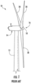
- FIGS. 1 and 2 illustrate a wind turbine 10 and associated power system suitable for use with the wind turbine 10 according to conventional construction.
- the wind turbine 10 includes a nacelle 14 that typically houses a generator 28 ( FIG. 2 ).
- the nacelle 14 is mounted on a tower 12 extending from a support surface (not shown).
- the wind turbine 10 also includes a rotor 16 that includes a plurality of rotor blades 20 attached to a rotating hub 18. As wind impacts the rotor blades 20, the blades 20 transform wind energy into a mechanical rotational torque that rotatably drives a low-speed shaft 22.
- the low-speed shaft 22 is configured to drive a gearbox 24 (where present) that subsequently steps up the low rotational speed of the low-speed shaft 22 to drive a high-speed shaft 26 at an increased rotational speed.
- the high-speed shaft 26 is generally rotatably coupled to a generator 28 (such as a doubly-fed induction generator or DFIG) so as to rotatably drive a generator rotor 30.
- a rotating magnetic field may be induced by the generator rotor 30 and a voltage may be induced within a generator stator 32 that is magnetically coupled to the generator rotor 30.
- the associated electrical power can be transmitted from the generator stator 32 to a main three-winding transformer 34 that is typically connected to a power grid via a grid breaker 36.
- the main transformer 34 steps up the voltage amplitude of the electrical power such that the transformed electrical power may be further transmitted to the power grid.
- the generator 28 is typically electrically coupled to a bidirectional power converter 38 that includes a rotor-side converter 40 joined to a line-side converter 42 via a regulated DC link 44.
- the rotor-side converter 40 converts the AC power provided from the rotor 30 into DC power and provides the DC power to the DC link 44.
- the line side converter 42 converts the DC power on the DC link 44 into AC output power suitable for the power grid.
- the AC power from the power converter 38 can be combined with the power from the stator 32 to provide multi-phase power (e.g. three-phase power) having a frequency maintained substantially at the frequency of the power grid (e.g. 50 Hz/60 Hz).
- the illustrated three-winding transformer 34 typically has (1) a 33 kilovolt (kV) medium voltage (MV) primary winding 33 connected to the power grid, (2) a 6 to 13.8 kV MV secondary winding 35 connected to the generator stator 32, and (3) a 690 to 900 volt (V) low-voltage (LV) tertiary winding 37 connected to the line-side power converter 42.
- kV medium voltage
- MV medium voltage
- LV low-voltage
- individual power systems of a plurality of wind turbines 10 may be arranged in a predetermined geological location and electrically connected together to form a wind farm 46. More specifically, as shown, the wind turbines 10 may be arranged into a plurality of groups 48 with each group separately connected to a main line 50 via switches 51, 52, 53, respectively. In addition, as shown, the main line 50 may be electrically coupled to another, larger transformer 54 for further stepping up the voltage amplitude of the electrical power from the groups 48 of wind turbines 10 before sending the power to the grid.
- harmonics Another issue that needs to be addressed in power systems is harmonics. For example, if the secondary winding is eliminated, this results in lower impedance in the system. Thus, there is an increased risk of such systems not meeting certain agency requirements for harmonics. Accordingly, power systems which include features for reducing the harmonic currents being injected into the power grid, particularly in view of agency harmonics requirements, would be advantageous.
- WECS wind energy conversion system
- the proposed WECS consists of induction generator, power electronic converters, and inductor capacitor inductor (LCL) harmonic filter.
- the research introduces a modified method for parameters selection of LCL harmonic filters and direct current (DC) link capacitance. Also it is provided a modified pitch angle controller and designs the control system for grid voltage supporting.
- MPPT maximum power point tracking
- MPPT maximum power point tracking
- a power converter can be used to provide a desired power to a load, such as a generator, motor, electrical grid, or other suitable load.
- the power converter can include a plurality of bridge circuits coupled in parallel.
- a bridge output of each of the parallel bridge circuits can be coupled together at the load instead of at the power converter.
- the parallel bridge circuits can be coupled together at a location that is physically proximate the physical location of the load, such as at a plurality of terminals associated with the load. By doing so, stray inductance associated with conductors used to couple the bridge outputs of the parallel bridge circuits to the load can be effectively coupled between the parallel bridge circuits.
- an electrical power subsystem for connection to a power grid according to claim 1 is provided.
- the electrical power subsystem includes a generator comprising a generator stator and a generator rotor, and a power converter electrically coupled to the generator.
- the power converter includes a plurality of rotor-side converters electrically coupled in parallel, a line-side converter, and a regulated DC link electrically coupling the plurality of rotor-side converters and the line-side converter.
- the electrical power subsystem further includes a stator power path for providing power from the generator stator to the power grid, a converter power path for providing power from the generator rotor through the power converter to the power grid, and a partial power transformer provided on the converter power path.
- the electrical power subsystem further includes a controller coupled to the power converter, the controller configured to coordinate switching of the plurality of rotor-side converters to produce an interleaved switching pattern between the plurality of rotor-side converters.
- the electrical power subsystem includes a generator including a generator stator and a generator rotor.
- the electrical power subsystem further includes a power converter electrically coupled to the generator, the power converter including a plurality of rotor-side converters electrically coupled in parallel, a line-side converter, and a regulated DC link electrically coupling the plurality of rotor-side converters and the line-side converter.
- the electrical power subsystem further includes a stator power path for providing power from the generator stator to the power grid, a converter power path for providing power from the generator rotor through the power converter to the power grid, and a partial power transformer provided on the converter power path.
- the method includes switching the plurality of rotor-side converters to produce an interleaved switching pattern between the plurality of rotor-side converters.
- An electrical power system in accordance with the present disclosure may include a generator and a power converter electrically coupled to the generator.
- the power converter may include a plurality of rotor-side converters electrically coupled in parallel with each other.
- the use of multiple rotor-side converters instead of only a single rotor-side converter advantageously facilitates the reduction in harmonics. In some cases, such multiple rotor-side converters can further result in the elimination or a change in the location of a harmonic filter in the system.
- switching patterns of the rotor-side converters may be coordinated to produce an interleaved switching pattern, with the switching phase of each rotor-side converter shifted from the others, resulting in significantly reduced harmonic currents being transmitted to the power grid.
- any necessary filtering equipment can be designed for operation at the higher frequency resulting from the interleaved switching pattern, thus advantageously resulting in physically smaller and less costly equipment.
- FIG. 4 a schematic diagram of one embodiment of an electrical power subsystem 102 according to the present disclosure is illustrated.
- the term "subsystem” is used herein to distinguish between the individual power systems (e.g. as shown in FIG. 4 or FIG. 2 ) and the overall electrical power system 105 of FIG. 5 or FIG. 3 that includes a plurality of electrical power subsystems 102.
- the electrical power subsystem 102 of FIG. 4 may also be referred to more generically, such as a simply a system (rather than a subsystem). Therefore, such terms may be used interchangeably and are not meant to be limiting.
- the electrical power subsystem 102 may correspond to a wind turbine power system 100. More specifically, as shown, the wind turbine power system 100 includes a rotor 104 that includes a plurality of rotor blades 106 attached to a rotating hub 108. As wind impacts the rotor blades 106, the blades 106 transform wind energy into a mechanical rotational torque that rotatably drives a low-speed shaft 110.
- the low-speed shaft 110 is configured to drive a gearbox 112 that subsequently steps up the low rotational speed of the low-speed shaft 110 to drive a high-speed shaft 114 at an increased rotational speed.
- the high-speed shaft 114 is generally rotatably coupled to a doubly-fed induction generator 116 (referred to hereinafter as DFIG 116) so as to rotatably drive a generator rotor 118.
- DFIG 116 doubly-fed induction generator 116
- a rotating magnetic field may be induced by the generator rotor 118 and a voltage may be induced within a generator stator 120 that is magnetically coupled to the generator rotor 118.
- the generator 116 is configured to convert the rotational mechanical energy to a sinusoidal, three-phase alternating current (AC) electrical energy signal in the generator stator 120.
- AC alternating current
- the generator 116 is electrically coupled to a bidirectional power converter 122 that includes a rotor-side converter 124 joined to a line-side converter 126 via a regulated DC link 128.
- the rotor-side converter 124 converts the AC power provided from the generator rotor 118 into DC power and provides the DC power to the DC link 128.
- the line side converter 126 converts the DC power on the DC link 128 into AC output power suitable for the power grid.
- the AC power from the power converter 122 can be combined with the power from the generator stator 120 via a converter power path 127 and a stator power path 125, respectively.
- a converter power path 127 and a stator power path 125 respectively.
- the converter power path 127 may include a partial power transformer 130 for stepping up the voltage amplitude of the electrical power from the power converter 122 such that the transformed electrical power may be further transmitted to the power grid.
- the illustrated system 102 of FIG. 4 does not include the conventional three-winding main transformer described above.
- the partial power transformer 130 may correspond to a two-winding transformer having a primary winding 132 connected to the power grid and a secondary winding 134 connected to the line side converter 126.
- the partial power transformer may in some embodiments include a third auxiliary winding for auxiliary loads.
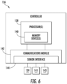
- the electrical power subsystem 102 may include a controller 136 configured to control any of the components of the wind turbine 100 and/or implement the method steps as described herein.
- the controller 136 may include one or more processor(s) 138 and associated memory device(s) 140 configured to perform a variety of computer-implemented functions (e.g., performing the methods, steps, calculations and the like and storing relevant data as disclosed herein).
- the controller 136 may also include a communications module 142 to facilitate communications between the controller 136 and the various components of the wind turbine 100, e.g. any of the components of FIGS. 4 and 5 .
- the communications module 142 may include a sensor interface 144 (e.g., one or more analog-to-digital converters) to permit signals transmitted from one or more sensors 139, 141, 143 to be converted into signals that can be understood and processed by the processors 138.
- the sensors 139, 141, 143 may be communicatively coupled to the communications module 142 using any suitable means.
- the sensors 139, 141, 143 may be coupled to the sensor interface 144 via a wired connection.
- the sensors 139, 141, 143 may be coupled to the sensor interface 144 via a wireless connection, such as by using any suitable wireless communications protocol known in the art.
- the processor 138 may be configured to receive one or more signals from the sensors 139, 141, 143.
- processor refers not only to integrated circuits referred to in the art as being included in a computer, but also refers to a controller, a microcontroller, a microcomputer, a programmable logic controller (PLC), an application specific integrated circuit, and other programmable circuits.
- the processor 138 is also configured to compute advanced control algorithms and communicate to a variety of Ethernet or serial-based protocols (Modbus, OPC, CAN, etc.).
- the memory device(s) 140 may generally comprise memory element(s) including, but not limited to, computer readable medium (e.g., random access memory (RAM)), computer readable non-volatile medium (e.g., a flash memory), a floppy disk, a compact disc-read only memory (CD-ROM), a magnetooptical disk (MOD), a digital versatile disc (DVD) and/or other suitable memory elements.
- RAM random access memory
- RAM computer readable non-volatile medium
- CD-ROM compact disc-read only memory
- MOD magnetooptical disk
- DVD digital versatile disc
- Such memory device(s) 140 may generally be configured to store suitable computer-readable instructions that, when implemented by the processor(s) 138, configure the controller 136 to perform the various functions as described herein.
- alternating current (AC) power generated at the generator stator 120 by rotation of the rotor 104 is provided via a dual path to the grid, i.e. via the stator power path 125 and the converter power path 127.
- the rotor side converter 124 converts the AC power provided from the generator rotor 118 into DC power and provides the DC power to the DC link 128.
- Switching elements e.g. IGBTs
- the line side converter 126 converts the DC power on the DC link 128 into AC output power suitable for the grid.
- switching elements e.g.
- IGBTs used in bridge circuits of the line side converter 126 can be modulated to convert the DC power on the DC link 128 into AC power.
- the AC power from the power converter 122 can be combined with the power from the generator stator 120 to provide multi-phase power having a frequency maintained substantially at the frequency of the grid.
- the rotor side converter 124 and the line side converter 126 may have any configuration using any switching devices that facilitate operation of electrical power system as described herein.
- the power converter 122 may be coupled in electronic data communication with the turbine controller 136 and/or a separate or integral converter controller 154 to control the operation of the rotor side converter 124 and the line side converter 126.
- the controller 136 may be configured to receive one or more voltage and/or electric current measurement signals from the first set of voltage and electric current sensors 139, 141, 143.
- the controller 136 may be configured to monitor and control at least some of the operational variables associated with the wind turbine 100 via the sensors 139, 141, 143.
- the sensors 139, 141, 143 may be electrically coupled to any portion of electrical power subsystem 102 that facilitates operation of electrical power subsystem 102 as described herein.
- the converter controller 154 is configured to receive one or more voltage and/or electric current feedback signals from the sensors 139, 141, 143. More specifically, in certain embodiments, the current or voltage feedback signals may include at least one of line feedback signals, line-side converter feedback signals, rotor-side converter feedback signals, or stator feedback signals.
- individual power systems may be arranged in at least two clusters 137 to form an electrical power system 105. More specifically, as shown, the wind turbine power systems 100 may be arranged into a plurality of clusters 137 so as to form a wind farm. Thus, as shown, each cluster 137 may be connected to a separate cluster transformer 145, 146, 147 via switches 151, 152, 153, respectively, for stepping up the voltage amplitude of the electrical power from each cluster 137 such that the transformed electrical power may be further transmitted to the power grid.
- the transformers 145, 146, 147 are connected to a main line 148 that combines the power from each cluster 137 before sending the power to the grid.
- the stator power circuit of all the wind turbines 100 share a common ground reference provided by the neutral of the secondary winding 124 of the cluster transformer 145, 146, 147 or by a separate neutral grounding transformer.
- Each subsystem 102 may be connected to the cluster 137 via a subsystem breaker 135, as shown.
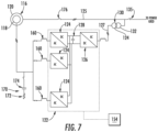
- FIGS. 7 through 10 various embodiments of electrical power subsystems 102 having improved harmonic reduction features are provided. It should be noted that, while such embodiments are illustrated in the context of subsystems using partial power transformers 130, such improved harmonic reduction features are equally applicable to subsystems using transformers 34, and such subsystems with such features are also within the scope and spirit of the present disclosure.
- the power converter 122 may include a plurality of rotor side converters 124 rather than only a single rotor side converter 124.
- the rotor side converters 124 may be electrically coupled to each other and the DC link 128 in parallel, as shown.
- the use of multiple rotor side converters 124 may facilitate the reduction in harmonics.
- the switching frequency components from the rotor side converter which typically contribute to the harmonic content include, for example: FSW + / ⁇ N Fslip where FSW is switching frequency of the rotor-side converter; Fslip is fundamental frequency of the output voltage/current of the rotor-side converter; and N is a positive integer number. Accordingly, as the power rating of the subsystem 102 increases, additional rotor side converters 124 may be added. Such additional rotor side converters 124 may both meet higher current requirements and facilitate reduced harmonics.
- three or more rotor-side converters 124 may be utilized. In other embodiments, as illustrated in FIG. 9 , only two rotor side-converters 124 may be utilized.
- An inductor 160 may be electrically coupled to each rotor-side converter 124. As particularly illustrated in FIG. 9 , in some embodiments, the inductors 160 may be magnetically coupled, such as via an interface or common-mode transformer 162. Such magnetic coupling may aid in harmonics filtering.
- a controller 154 (which may be separate from or a component of controller 136) may be communicatively coupled to the power converter 122 for controlling operation of the power converter 122.
- the controller 154 may be communicatively coupled to each of the plurality of rotor-side converters 124, and may thus control modulation of the switching elements (e.g. IGBTs) used in bridge circuits of each rotor side converter 124.
- the switching elements e.g. IGBTs
- the controller 154 may be configured to coordinate switching of the plurality of rotor-side converters 124 to produce an interleaved switching pattern between the plurality of rotor-side converters 124.
- Such interleaved switching pattern may reduce or eliminate harmonics as discussed herein.
- the controller 154 may shift the switching phase of each the plurality of rotor-side converters 124 to be out of phase with the others of the rotor side converters 124, thus resulting in an interleaved switching pattern.
- the phase of each of the plurality of rotor-side converters 124 is shifted from others of the plurality of rotor-side converters 124 by the result of 360 degrees divided by the total number of rotor-side converters, plus or minus 15 degrees, such as plus or minus 10 degrees, such as plus or minus 5 degrees, such as plus or minus 2 degrees.
- either the phase of the switching waveform can be shifted and the fundamental reference waveform kept the same or the fundamental reference waveform shifted and the switching waveform kept the same.
- a first one of the converters 124 may switch at the switching phase with no adjustment and a second one of the converters 124 may have its switching phase adjusted by 180 degrees, such that the phase of each of the two converters 124 is shifted from the other converter 124 by 180 degrees.
- a first one of the converters 124 may switch at the switching phase with no adjustment and the other two converters 124 may have their switching phases adjusted by 120 and 240 degrees, respectively, such that the phase of each of the three converters 124 is shifted from others of the converters 124 by 120 degrees.
- a first one of the converters 124 may switch at the switching phase with no adjustment and the other three converters 124 may have their switching phases adjusted by 90, 180, and 270 degrees, respectively, such that the phase of each of the four converters 124 is shifted from others of the converters 124 by 90 degrees. All of these described examples may utilized exact degrees as described or approximate degrees of plus or minus 15, 10, 5, or 2 degrees.
- FIG. 10 is a graph illustrating one embodiment of coordinating switching of rotor-side converters 124 to produce an interleaved switching pattern.
- three converters 124 are utilized, as shown. As a result of such shifting the carrier wave for each converter 124 is shifted to produce an interleaved switching pattern.
- the substation 102 may further include a harmonic filter 170.
- the harmonic filter 170 may, for example, include a resistor 172 and a capacitor 174 in series, or may have another suitable configuration.
- the harmonic filter 170 may be on the converter power path 127, such as between the generator rotor 118 and the power converter 122, as illustrated in FIG. 7 .
- the harmonic filter 170 may be located in other advantageous locations since harmonics on the converter power path 127 may be minimized. For example, as illustrated in FIG.
- the harmonic filter 170 may be on the stator power path 125, such as between a stator power path synch switch or contactor 176 and the generator stator 120. In still other embodiments, no harmonic filter 170 may be necessary in the substation 102, as illustrated in FIG. 8 .
- a method may include, for example, the step of switching the plurality of rotor-side converters 124 to produce an interleaved switching pattern between the plurality of rotor-side converters 124.
Landscapes
- Engineering & Computer Science (AREA)
- Power Engineering (AREA)
- Control Of Eletrric Generators (AREA)
Applications Claiming Priority (2)
| Application Number | Priority Date | Filing Date | Title |
|---|---|---|---|
| US15/588,878 US10784685B2 (en) | 2017-05-08 | 2017-05-08 | Electrical power systems and subsystems |
| PCT/US2018/031307 WO2018208641A1 (en) | 2017-05-08 | 2018-05-07 | Electrical power systems and subsystems |
Publications (3)
| Publication Number | Publication Date |
|---|---|
| EP3622607A1 EP3622607A1 (en) | 2020-03-18 |
| EP3622607A4 EP3622607A4 (en) | 2021-01-06 |
| EP3622607B1 true EP3622607B1 (en) | 2025-06-25 |
Family
ID=64015024
Family Applications (1)
| Application Number | Title | Priority Date | Filing Date |
|---|---|---|---|
| EP18798349.9A Active EP3622607B1 (en) | 2017-05-08 | 2018-05-07 | Electrical power systems and subsystems |
Country Status (6)
| Country | Link |
|---|---|
| US (1) | US10784685B2 (da) |
| EP (1) | EP3622607B1 (da) |
| CN (1) | CN110603707B (da) |
| DK (1) | DK3622607T3 (da) |
| ES (1) | ES3041967T3 (da) |
| WO (1) | WO2018208641A1 (da) |
Families Citing this family (5)
| Publication number | Priority date | Publication date | Assignee | Title |
|---|---|---|---|---|
| DE102016108394A1 (de) * | 2016-05-06 | 2017-11-09 | Wobben Properties Gmbh | Verfahren zur Kompensation von einzuspeisenden Strömen eines Windparks |
| DE102017003078A1 (de) * | 2017-03-30 | 2018-10-04 | Senvion Gmbh | Windenergieanlage mit Speiseleitung |
| CN109149626B (zh) * | 2017-12-28 | 2022-01-25 | 北京金风科创风电设备有限公司 | 发电机组的运行控制方法、装置及系统 |
| AU2022353021A1 (en) * | 2021-09-22 | 2024-04-11 | Flexgen Power Systems, Llc | Electrical systems and methods using high capacity local bus supported by energy storage |
| EP4156479A1 (de) * | 2021-09-27 | 2023-03-29 | Wobben Properties GmbH | Steuereinheit und verfahren für einen umrichter |
Family Cites Families (32)
| Publication number | Priority date | Publication date | Assignee | Title |
|---|---|---|---|---|
| US3593106A (en) | 1970-03-11 | 1971-07-13 | Gen Electric | Cycloconverter with rectifier bank control for smooth switching between rectifier banks |
| US4281371A (en) | 1980-03-05 | 1981-07-28 | Westinghouse Electric Corp. | Cycloconverter with waveform improving nonlinear feedback |
| US5047910A (en) | 1990-07-09 | 1991-09-10 | Teledyne Inet | Ideal sinusoidal voltage waveform synthesis control system |
| JP2001268913A (ja) | 2000-03-17 | 2001-09-28 | Daikin Ind Ltd | 三相整流装置 |
| US7187566B2 (en) | 2000-03-17 | 2007-03-06 | Daikin Industries, Ltd. | Three-phase rectifier |
| DE10327344A1 (de) * | 2003-06-16 | 2005-01-27 | Repower Systems Ag | Windenergieanlage |
| US7119452B2 (en) | 2003-09-03 | 2006-10-10 | General Electric Company | Voltage control for wind generators |
| US7212421B2 (en) | 2005-03-15 | 2007-05-01 | Perfect Electric Power, Inc. | Combination feedback controller and power regulator using same |
| US7521907B2 (en) | 2006-03-06 | 2009-04-21 | Enpirion, Inc. | Controller for a power converter and method of operating the same |
| EP2128440A4 (en) | 2006-12-28 | 2012-03-14 | Wind To Power System S L | ASYNCHRONOUS GENERATOR WITH CONTROL OF THE VOLTAGE PLACED ON THE STATOR |
| US9587626B2 (en) | 2007-06-01 | 2017-03-07 | Acciona Windpower, S.A. | Control system and method for a wind turbine generator |
| US7847526B2 (en) * | 2007-09-28 | 2010-12-07 | General Electric Company | System and method for controlling torque ripples in synchronous machines |
| HRP20080209C1 (hr) | 2008-05-13 | 2018-08-10 | Saša Sladić | Jednofazni paralelni aktivni učinski filtar s adaptivnim naponom filterskog kondenzatora |
| US7928592B2 (en) * | 2008-06-30 | 2011-04-19 | General Electric Company | Wind turbine with parallel converters utilizing a plurality of isolated generator windings |
| US8120932B2 (en) * | 2008-07-01 | 2012-02-21 | American Superconductor Corporation | Low voltage ride through |
| US8041465B2 (en) | 2008-10-09 | 2011-10-18 | General Electric Company | Voltage control at windfarms |
| US8659178B2 (en) * | 2009-02-27 | 2014-02-25 | Acciona Windpower, S.A. | Wind turbine control method, control unit and wind turbine |
| JP5128568B2 (ja) * | 2009-09-30 | 2013-01-23 | 株式会社日立製作所 | 風力発電システムおよび制御法 |
| US7843078B2 (en) * | 2009-09-30 | 2010-11-30 | General Electric Company | Method and apparatus for generating power in a wind turbine |
| US7923862B2 (en) | 2009-10-06 | 2011-04-12 | General Electric Company | Reactive power regulation and voltage support for renewable energy plants |
| US8093741B2 (en) * | 2010-10-29 | 2012-01-10 | General Electric Company | Method and system for providing increased turbine output for doubly fed induction generator |
| EP2466737A3 (en) | 2010-12-17 | 2016-04-27 | Vestas Wind Systems A/S | A wind turbine generator |
| CN103208812B (zh) * | 2012-01-17 | 2015-04-29 | 台达电子企业管理(上海)有限公司 | 风电变流器结构及包含其的风力发电系统 |
| US9653984B2 (en) | 2012-04-30 | 2017-05-16 | Rockwell Automation Technologies, Inc. | Filter capacitor degradation detection apparatus and method |
| US9667128B2 (en) | 2012-04-30 | 2017-05-30 | Rockwell Automation Technologies, Inc. | Power converter resonance detection apparatus and method |
| US8669669B1 (en) | 2012-09-13 | 2014-03-11 | General Electric Company | Voltage control in a doubly-fed induction generator wind turbine system |
| CN103825474B (zh) * | 2012-11-16 | 2016-08-31 | 台达电子工业股份有限公司 | 低共模噪声的电源变换装置及其应用系统 |
| US9343991B2 (en) * | 2013-01-18 | 2016-05-17 | General Electric Company | Current balance control for non-interleaved parallel bridge circuits in power converter |
| US20140203559A1 (en) * | 2013-01-18 | 2014-07-24 | General Electric Company | Connection for improved current balancing between parallel bridge circuits |
| US9537437B2 (en) * | 2013-03-04 | 2017-01-03 | General Electric Company | Method and system for controlling switching frequency of a doubly-fed induction generator (DFIG) |
| US9318944B2 (en) | 2013-04-29 | 2016-04-19 | Rockwell Automation Technologies, Inc. | Methods and apparatus for active front end filter capacitor degradation detection |
| CN105703391A (zh) * | 2014-12-12 | 2016-06-22 | 通用电气公司 | 发电系统和操作发电系统的相关方法 |
-
2017
- 2017-05-08 US US15/588,878 patent/US10784685B2/en active Active
-
2018
- 2018-05-07 CN CN201880030773.0A patent/CN110603707B/zh active Active
- 2018-05-07 WO PCT/US2018/031307 patent/WO2018208641A1/en not_active Ceased
- 2018-05-07 ES ES18798349T patent/ES3041967T3/es active Active
- 2018-05-07 EP EP18798349.9A patent/EP3622607B1/en active Active
- 2018-05-07 DK DK18798349.9T patent/DK3622607T3/da active
Non-Patent Citations (2)
| Title |
|---|
| ENERNEX LLC: "DOE ARRA Project Documentation, User Support, and Verification of Wind Turbine and Plant Models", 18 September 2012 (2012-09-18), pages 1 - 247, XP093026943, Retrieved from the Internet <URL:http://www.osti.gov/bridge/servlets/purl/1051403/1051403.pdf> [retrieved on 20230224], DOI: https://doi.org/10.2172/1051403 * |
| MOSA MAGDI: "WIND GENERATOR GRID INTERFACE USING PWM CONVERTER RE- Thesis for the degree of MASTER OF SCIENCE In Electrical Engineering - Alliance Project View project", 31 August 2013 (2013-08-31), pages 1 - 226, XP093026938, Retrieved from the Internet <URL:https://www.researchgate.net/profile/Magdi-Mosa/publication/351194520_WIND_GENERATOR_GRID_INTERFACE_USING_PWM_CONVERTER/links/608b14e192851c490fa76a16/WIND-GENERATOR-GRID-INTERFACE-USING-PWM-CONVERTER.pdf> [retrieved on 20230224], DOI: 10.13140/RG.2.2.21433.29282 * |
Also Published As
| Publication number | Publication date |
|---|---|
| ES3041967T3 (en) | 2025-11-17 |
| DK3622607T3 (da) | 2025-09-29 |
| US10784685B2 (en) | 2020-09-22 |
| EP3622607A4 (en) | 2021-01-06 |
| CN110603707A (zh) | 2019-12-20 |
| CN110603707B (zh) | 2023-03-21 |
| US20180323619A1 (en) | 2018-11-08 |
| EP3622607A1 (en) | 2020-03-18 |
| WO2018208641A1 (en) | 2018-11-15 |
Similar Documents
| Publication | Publication Date | Title |
|---|---|---|
| CN102035309B (zh) | 用于在风力涡轮机中产生功率的方法及设备 | |
| EP3214719A1 (en) | System and method for controlling dc link voltage of a power converter for doubly-fed induction generators | |
| EP3276819B1 (en) | Electrical power circuit and method of operating same | |
| EP3619785B1 (en) | Electrical power systems having reactive power and harmonic support components | |
| US10784685B2 (en) | Electrical power systems and subsystems | |
| EP3410555B1 (en) | Electrical power systems having zig-zag transformers | |
| EP3745551B1 (en) | System and method for controlling harmonics in a renewable energy power system | |
| EP3631933B1 (en) | Electrical power systems and subsystems | |
| EP3622617B1 (en) | Electrical power systems and methods using distortion filters | |
| US10218298B2 (en) | Spillover of reactive current to line side converter | |
| US10288040B2 (en) | Current limit calculation for wind turbine control | |
| EP3799246B1 (en) | Electrical power systems having a cluster transformer with multiple primary windings | |
| WO2018231548A1 (en) | Electrical power subsystems and methods for controlling same | |
| US10865773B1 (en) | System and method for mitigating flicker in a power grid from a wind turbine power system |
Legal Events
| Date | Code | Title | Description |
|---|---|---|---|
| STAA | Information on the status of an ep patent application or granted ep patent |
Free format text: STATUS: THE INTERNATIONAL PUBLICATION HAS BEEN MADE |
|
| PUAI | Public reference made under article 153(3) epc to a published international application that has entered the european phase |
Free format text: ORIGINAL CODE: 0009012 |
|
| STAA | Information on the status of an ep patent application or granted ep patent |
Free format text: STATUS: REQUEST FOR EXAMINATION WAS MADE |
|
| 17P | Request for examination filed |
Effective date: 20191203 |
|
| AK | Designated contracting states |
Kind code of ref document: A1 Designated state(s): AL AT BE BG CH CY CZ DE DK EE ES FI FR GB GR HR HU IE IS IT LI LT LU LV MC MK MT NL NO PL PT RO RS SE SI SK SM TR |
|
| AX | Request for extension of the european patent |
Extension state: BA ME |
|
| DAV | Request for validation of the european patent (deleted) | ||
| DAX | Request for extension of the european patent (deleted) | ||
| A4 | Supplementary search report drawn up and despatched |
Effective date: 20201204 |
|
| RIC1 | Information provided on ipc code assigned before grant |
Ipc: H02J 3/38 20060101AFI20201130BHEP Ipc: H02M 1/12 20060101ALI20201130BHEP Ipc: H02M 3/158 20060101ALI20201130BHEP |
|
| STAA | Information on the status of an ep patent application or granted ep patent |
Free format text: STATUS: EXAMINATION IS IN PROGRESS |
|
| 17Q | First examination report despatched |
Effective date: 20230424 |
|
| P01 | Opt-out of the competence of the unified patent court (upc) registered |
Effective date: 20230530 |
|
| RAP1 | Party data changed (applicant data changed or rights of an application transferred) |
Owner name: GENERAL ELECTRIC RENOVABLES ESPANA, S.L. |
|
| REG | Reference to a national code |
Ref country code: DE Free format text: PREVIOUS MAIN CLASS: H02J0003380000 Ref country code: DE Ref legal event code: R079 Ref document number: 602018082953 Country of ref document: DE Free format text: PREVIOUS MAIN CLASS: H02J0003380000 Ipc: H02J0003460000 |
|
| GRAP | Despatch of communication of intention to grant a patent |
Free format text: ORIGINAL CODE: EPIDOSNIGR1 |
|
| STAA | Information on the status of an ep patent application or granted ep patent |
Free format text: STATUS: GRANT OF PATENT IS INTENDED |
|
| RIC1 | Information provided on ipc code assigned before grant |
Ipc: H02M 5/458 20060101ALI20250203BHEP Ipc: H02J 3/46 20060101AFI20250203BHEP |
|
| INTG | Intention to grant announced |
Effective date: 20250213 |
|
| GRAJ | Information related to disapproval of communication of intention to grant by the applicant or resumption of examination proceedings by the epo deleted |
Free format text: ORIGINAL CODE: EPIDOSDIGR1 |
|
| STAA | Information on the status of an ep patent application or granted ep patent |
Free format text: STATUS: EXAMINATION IS IN PROGRESS |
|
| GRAP | Despatch of communication of intention to grant a patent |
Free format text: ORIGINAL CODE: EPIDOSNIGR1 |
|
| STAA | Information on the status of an ep patent application or granted ep patent |
Free format text: STATUS: GRANT OF PATENT IS INTENDED |
|
| INTC | Intention to grant announced (deleted) | ||
| INTG | Intention to grant announced |
Effective date: 20250328 |
|
| GRAS | Grant fee paid |
Free format text: ORIGINAL CODE: EPIDOSNIGR3 |
|
| GRAA | (expected) grant |
Free format text: ORIGINAL CODE: 0009210 |
|
| STAA | Information on the status of an ep patent application or granted ep patent |
Free format text: STATUS: THE PATENT HAS BEEN GRANTED |
|
| AK | Designated contracting states |
Kind code of ref document: B1 Designated state(s): AL AT BE BG CH CY CZ DE DK EE ES FI FR GB GR HR HU IE IS IT LI LT LU LV MC MK MT NL NO PL PT RO RS SE SI SK SM TR |
|
| REG | Reference to a national code |
Ref country code: GB Ref legal event code: FG4D |
|
| REG | Reference to a national code |
Ref country code: CH Ref legal event code: EP |
|
| REG | Reference to a national code |
Ref country code: DE Ref legal event code: R096 Ref document number: 602018082953 Country of ref document: DE |
|
| REG | Reference to a national code |
Ref country code: CH Ref legal event code: EP |
|
| REG | Reference to a national code |
Ref country code: IE Ref legal event code: FG4D |
|
| REG | Reference to a national code |
Ref country code: DK Ref legal event code: T3 Effective date: 20250925 |
|
| PG25 | Lapsed in a contracting state [announced via postgrant information from national office to epo] |
Ref country code: FI Free format text: LAPSE BECAUSE OF FAILURE TO SUBMIT A TRANSLATION OF THE DESCRIPTION OR TO PAY THE FEE WITHIN THE PRESCRIBED TIME-LIMIT Effective date: 20250625 |
|
| REG | Reference to a national code |
Ref country code: LT Ref legal event code: MG9D |
|
| PG25 | Lapsed in a contracting state [announced via postgrant information from national office to epo] |
Ref country code: NO Free format text: LAPSE BECAUSE OF FAILURE TO SUBMIT A TRANSLATION OF THE DESCRIPTION OR TO PAY THE FEE WITHIN THE PRESCRIBED TIME-LIMIT Effective date: 20250925 Ref country code: GR Free format text: LAPSE BECAUSE OF FAILURE TO SUBMIT A TRANSLATION OF THE DESCRIPTION OR TO PAY THE FEE WITHIN THE PRESCRIBED TIME-LIMIT Effective date: 20250926 |
|
| PG25 | Lapsed in a contracting state [announced via postgrant information from national office to epo] |
Ref country code: BG Free format text: LAPSE BECAUSE OF FAILURE TO SUBMIT A TRANSLATION OF THE DESCRIPTION OR TO PAY THE FEE WITHIN THE PRESCRIBED TIME-LIMIT Effective date: 20250625 |
|
| PG25 | Lapsed in a contracting state [announced via postgrant information from national office to epo] |
Ref country code: HR Free format text: LAPSE BECAUSE OF FAILURE TO SUBMIT A TRANSLATION OF THE DESCRIPTION OR TO PAY THE FEE WITHIN THE PRESCRIBED TIME-LIMIT Effective date: 20250625 |
|
| PG25 | Lapsed in a contracting state [announced via postgrant information from national office to epo] |
Ref country code: RS Free format text: LAPSE BECAUSE OF FAILURE TO SUBMIT A TRANSLATION OF THE DESCRIPTION OR TO PAY THE FEE WITHIN THE PRESCRIBED TIME-LIMIT Effective date: 20250925 |
|
| PG25 | Lapsed in a contracting state [announced via postgrant information from national office to epo] |
Ref country code: LV Free format text: LAPSE BECAUSE OF FAILURE TO SUBMIT A TRANSLATION OF THE DESCRIPTION OR TO PAY THE FEE WITHIN THE PRESCRIBED TIME-LIMIT Effective date: 20250625 |
|
| REG | Reference to a national code |
Ref country code: NL Ref legal event code: MP Effective date: 20250625 |
|
| PG25 | Lapsed in a contracting state [announced via postgrant information from national office to epo] |
Ref country code: NL Free format text: LAPSE BECAUSE OF FAILURE TO SUBMIT A TRANSLATION OF THE DESCRIPTION OR TO PAY THE FEE WITHIN THE PRESCRIBED TIME-LIMIT Effective date: 20250625 |
|
| REG | Reference to a national code |
Ref country code: ES Ref legal event code: FG2A Ref document number: 3041967 Country of ref document: ES Kind code of ref document: T3 Effective date: 20251117 |
|
| PG25 | Lapsed in a contracting state [announced via postgrant information from national office to epo] |
Ref country code: PT Free format text: LAPSE BECAUSE OF FAILURE TO SUBMIT A TRANSLATION OF THE DESCRIPTION OR TO PAY THE FEE WITHIN THE PRESCRIBED TIME-LIMIT Effective date: 20251027 |
|
| REG | Reference to a national code |
Ref country code: AT Ref legal event code: MK05 Ref document number: 1807612 Country of ref document: AT Kind code of ref document: T Effective date: 20250625 |
|
| PG25 | Lapsed in a contracting state [announced via postgrant information from national office to epo] |
Ref country code: IS Free format text: LAPSE BECAUSE OF FAILURE TO SUBMIT A TRANSLATION OF THE DESCRIPTION OR TO PAY THE FEE WITHIN THE PRESCRIBED TIME-LIMIT Effective date: 20251025 |
|
| PG25 | Lapsed in a contracting state [announced via postgrant information from national office to epo] |
Ref country code: AT Free format text: LAPSE BECAUSE OF FAILURE TO SUBMIT A TRANSLATION OF THE DESCRIPTION OR TO PAY THE FEE WITHIN THE PRESCRIBED TIME-LIMIT Effective date: 20250625 Ref country code: SM Free format text: LAPSE BECAUSE OF FAILURE TO SUBMIT A TRANSLATION OF THE DESCRIPTION OR TO PAY THE FEE WITHIN THE PRESCRIBED TIME-LIMIT Effective date: 20250625 |
|
| PG25 | Lapsed in a contracting state [announced via postgrant information from national office to epo] |
Ref country code: CZ Free format text: LAPSE BECAUSE OF FAILURE TO SUBMIT A TRANSLATION OF THE DESCRIPTION OR TO PAY THE FEE WITHIN THE PRESCRIBED TIME-LIMIT Effective date: 20250625 |
|
| PG25 | Lapsed in a contracting state [announced via postgrant information from national office to epo] |
Ref country code: PL Free format text: LAPSE BECAUSE OF FAILURE TO SUBMIT A TRANSLATION OF THE DESCRIPTION OR TO PAY THE FEE WITHIN THE PRESCRIBED TIME-LIMIT Effective date: 20250625 |
|
| PG25 | Lapsed in a contracting state [announced via postgrant information from national office to epo] |
Ref country code: EE Free format text: LAPSE BECAUSE OF FAILURE TO SUBMIT A TRANSLATION OF THE DESCRIPTION OR TO PAY THE FEE WITHIN THE PRESCRIBED TIME-LIMIT Effective date: 20250625 |
|
| PG25 | Lapsed in a contracting state [announced via postgrant information from national office to epo] |
Ref country code: SK Free format text: LAPSE BECAUSE OF FAILURE TO SUBMIT A TRANSLATION OF THE DESCRIPTION OR TO PAY THE FEE WITHIN THE PRESCRIBED TIME-LIMIT Effective date: 20250625 |
|
| PG25 | Lapsed in a contracting state [announced via postgrant information from national office to epo] |
Ref country code: IT Free format text: LAPSE BECAUSE OF FAILURE TO SUBMIT A TRANSLATION OF THE DESCRIPTION OR TO PAY THE FEE WITHIN THE PRESCRIBED TIME-LIMIT Effective date: 20250625 |
|
| PLBE | No opposition filed within time limit |
Free format text: ORIGINAL CODE: 0009261 |
|
| STAA | Information on the status of an ep patent application or granted ep patent |
Free format text: STATUS: NO OPPOSITION FILED WITHIN TIME LIMIT |
|
| REG | Reference to a national code |
Ref country code: CH Ref legal event code: L10 Free format text: ST27 STATUS EVENT CODE: U-0-0-L10-L00 (AS PROVIDED BY THE NATIONAL OFFICE) Effective date: 20260507 |