EP3621145A1 - Cavity-type radio frequency filter - Google Patents
Cavity-type radio frequency filter Download PDFInfo
- Publication number
- EP3621145A1 EP3621145A1 EP18794866.6A EP18794866A EP3621145A1 EP 3621145 A1 EP3621145 A1 EP 3621145A1 EP 18794866 A EP18794866 A EP 18794866A EP 3621145 A1 EP3621145 A1 EP 3621145A1
- Authority
- EP
- European Patent Office
- Prior art keywords
- cover
- enclosure
- frequency tuning
- fixing member
- resilient
- Prior art date
- Legal status (The legal status is an assumption and is not a legal conclusion. Google has not performed a legal analysis and makes no representation as to the accuracy of the status listed.)
- Granted
Links
Images


Classifications
-
- H—ELECTRICITY
- H01—ELECTRIC ELEMENTS
- H01P—WAVEGUIDES; RESONATORS, LINES, OR OTHER DEVICES OF THE WAVEGUIDE TYPE
- H01P1/00—Auxiliary devices
- H01P1/20—Frequency-selective devices, e.g. filters
- H01P1/207—Hollow waveguide filters
-
- H—ELECTRICITY
- H01—ELECTRIC ELEMENTS
- H01P—WAVEGUIDES; RESONATORS, LINES, OR OTHER DEVICES OF THE WAVEGUIDE TYPE
- H01P1/00—Auxiliary devices
- H01P1/20—Frequency-selective devices, e.g. filters
- H01P1/201—Filters for transverse electromagnetic waves
- H01P1/205—Comb or interdigital filters; Cascaded coaxial cavities
- H01P1/2053—Comb or interdigital filters; Cascaded coaxial cavities the coaxial cavity resonators being disposed parall to each other
-
- H—ELECTRICITY
- H01—ELECTRIC ELEMENTS
- H01P—WAVEGUIDES; RESONATORS, LINES, OR OTHER DEVICES OF THE WAVEGUIDE TYPE
- H01P1/00—Auxiliary devices
- H01P1/20—Frequency-selective devices, e.g. filters
- H01P1/201—Filters for transverse electromagnetic waves
- H01P1/202—Coaxial filters
-
- H—ELECTRICITY
- H01—ELECTRIC ELEMENTS
- H01P—WAVEGUIDES; RESONATORS, LINES, OR OTHER DEVICES OF THE WAVEGUIDE TYPE
- H01P1/00—Auxiliary devices
- H01P1/20—Frequency-selective devices, e.g. filters
- H01P1/201—Filters for transverse electromagnetic waves
- H01P1/205—Comb or interdigital filters; Cascaded coaxial cavities
-
- H—ELECTRICITY
- H01—ELECTRIC ELEMENTS
- H01P—WAVEGUIDES; RESONATORS, LINES, OR OTHER DEVICES OF THE WAVEGUIDE TYPE
- H01P1/00—Auxiliary devices
- H01P1/20—Frequency-selective devices, e.g. filters
- H01P1/207—Hollow waveguide filters
- H01P1/208—Cascaded cavities; Cascaded resonators inside a hollow waveguide structure
- H01P1/2084—Cascaded cavities; Cascaded resonators inside a hollow waveguide structure with dielectric resonators
-
- H—ELECTRICITY
- H01—ELECTRIC ELEMENTS
- H01P—WAVEGUIDES; RESONATORS, LINES, OR OTHER DEVICES OF THE WAVEGUIDE TYPE
- H01P11/00—Apparatus or processes specially adapted for manufacturing waveguides or resonators, lines, or other devices of the waveguide type
- H01P11/007—Manufacturing frequency-selective devices
-
- H—ELECTRICITY
- H01—ELECTRIC ELEMENTS
- H01P—WAVEGUIDES; RESONATORS, LINES, OR OTHER DEVICES OF THE WAVEGUIDE TYPE
- H01P7/00—Resonators of the waveguide type
- H01P7/04—Coaxial resonators
-
- H—ELECTRICITY
- H01—ELECTRIC ELEMENTS
- H01P—WAVEGUIDES; RESONATORS, LINES, OR OTHER DEVICES OF THE WAVEGUIDE TYPE
- H01P7/00—Resonators of the waveguide type
- H01P7/06—Cavity resonators
-
- H—ELECTRICITY
- H01—ELECTRIC ELEMENTS
- H01P—WAVEGUIDES; RESONATORS, LINES, OR OTHER DEVICES OF THE WAVEGUIDE TYPE
- H01P7/00—Resonators of the waveguide type
- H01P7/10—Dielectric resonators
-
- F—MECHANICAL ENGINEERING; LIGHTING; HEATING; WEAPONS; BLASTING
- F16—ENGINEERING ELEMENTS AND UNITS; GENERAL MEASURES FOR PRODUCING AND MAINTAINING EFFECTIVE FUNCTIONING OF MACHINES OR INSTALLATIONS; THERMAL INSULATION IN GENERAL
- F16B—DEVICES FOR FASTENING OR SECURING CONSTRUCTIONAL ELEMENTS OR MACHINE PARTS TOGETHER, e.g. NAILS, BOLTS, CIRCLIPS, CLAMPS, CLIPS OR WEDGES; JOINTS OR JOINTING
- F16B39/00—Locking of screws, bolts or nuts
- F16B39/22—Locking of screws, bolts or nuts in which the locking takes place during screwing down or tightening
- F16B39/24—Locking of screws, bolts or nuts in which the locking takes place during screwing down or tightening by means of washers, spring washers, or resilient plates that lock against the object
- F16B39/26—Locking of screws, bolts or nuts in which the locking takes place during screwing down or tightening by means of washers, spring washers, or resilient plates that lock against the object with spring washers fastened to the nut or bolt-head
-
- F—MECHANICAL ENGINEERING; LIGHTING; HEATING; WEAPONS; BLASTING
- F16—ENGINEERING ELEMENTS AND UNITS; GENERAL MEASURES FOR PRODUCING AND MAINTAINING EFFECTIVE FUNCTIONING OF MACHINES OR INSTALLATIONS; THERMAL INSULATION IN GENERAL
- F16B—DEVICES FOR FASTENING OR SECURING CONSTRUCTIONAL ELEMENTS OR MACHINE PARTS TOGETHER, e.g. NAILS, BOLTS, CIRCLIPS, CLAMPS, CLIPS OR WEDGES; JOINTS OR JOINTING
- F16B43/00—Washers or equivalent devices; Other devices for supporting bolt-heads or nuts
- F16B43/004—Washers or equivalent devices; Other devices for supporting bolt-heads or nuts with a radial cut in order to improve elasticity of the washer
Definitions
- the present disclosure in some embodiments relates to a radio signal processing apparatus for use in a wireless communication system. More particularly, the present disclosure relates to a cavity-type radio frequency filter (hereinafter, abbreviated as 'filter'), such as a cavity filter.
- 'filter' a cavity-type radio frequency filter
- a radio frequency filter having a cavity structure generally utilizes a metallic enclosure for providing a plurality of accommodation spaces or cavities having a shape such as rectangular parallelepiped and the like, in which dielectric resonant elements (DR) or resonant elements composed of a metallic resonance rod are each provided for generating superhigh frequency resonance.
- DR dielectric resonant elements
- such cavity-type radio frequency filter is generally provided at its upper portion with a cover for shielding the open areas of the corresponding cavities, where the cover may have, as a configuration for tuning the filtering characteristic of the radio frequency filter, a plurality of tuning screws and nuts for fixing the corresponding tuning screws.
- An example cavity-type radio frequency filter is disclosed by Korean Patent Application Publication No. 10-2004-100084 (entitled “Radio Frequency Filter” and published on December 2, 2004; inventors: Park, Jonggyu and 2 others) filed by the present applicant.
- Those cavity-type radio frequency filters are used for processing radio transmit and receive signals in a radio communication system. Particularly in mobile communication systems, the cavity-type radio frequency filters are typically used for base stations, repeaters or relays and the like.
- Korean Patent Application Publication No. 10-2014-0026235 (entitled 'Radio Frequency Filter with Cavity Structure', published March 5, 2014, and invented by PARK, Nam Sin and 2 others) filed by the present applicant suggests a simplified filter structure for enabling easy frequency tuning without employing a coupling structure of tuning screws and fastening nuts.
- the above-mentioned Patent Application Publication No. 10-2014-0026235 suggests, when making a cover by pressing, die-casting or other processing of a plate-like base material of aluminum or magnesium material (including an alloy), to form one or more depressions at positions in the cover corresponding to resonant elements.
- a plurality of dot peen structures are formed at the depressions by embossing or pressing by embossing pins of an external embossing machine.
- Such a depression and dot peen structure are intended to replace the coupling structure of tuning screws and fastening nuts which have been conventionally used for frequency tuning, and to achieve appropriate tuning by narrowing the distance between the depression (and the dot peen structure) and the resonant element.
- the present disclosure in some embodiments seeks to provide a simpler cavity-type radio frequency filter which is simpler, more compact and lighter, and which enables simpler manufacturing operation with lower cost.
- the cavity-type radio frequency filter according to at least some embodiments of the present disclosure has a frequency tuning structure that can reversibly perform the frequency tuning operation, thereby making the tuning operation more efficient and easier.
- At least one embodiment of the present disclosure provides a radio frequency filter having a cavity structure including an enclosure, a resonant element, a cover, a frequency tuning screw, and a resilient fixing member.
- the enclosure has a hollow inside and an open surface on one side to have a cavity.
- the resonant element is positioned in the hollow of the enclosure.
- the cover has a screw hole having a preset diameter at a position corresponding to the resonant element, and is configured to seal the open surface of the enclosure.
- the frequency tuning screw is configured to be screwed into the screw hole of the cover, and it has an upper end formed at least partially with a latching abutment that protrudes outwardly.
- the resilient fixing member is configured to be caught on the latching abutment of the frequency tuning screw and coupled between the frequency tuning screw and the cover, to be annular and planar in shape having a hollow portion, and to be generally tapered in cross section with a lower outer diameter narrowing into an upper inner diameter toward the hollow portion, and to have a predetermined spring force.
- a radio frequency filter having a cavity structure including an enclosure, a resonant element, a cover, and a frequency tuning screw.
- the enclosure has a hollow inside and an open surface on one side to have a cavity.
- the resonant element is positioned in the hollow of the enclosure.
- the cover has a screw hole having a preset diameter at a position corresponding to the resonant element, and it is configured to seal the open surface of the enclosure.
- the frequency tuning screw is configured to be screwed into the screw hole of the cover.
- the frequency tuning screw has an upper end formed at least partially with a resilient fixing member having a predetermined spring force, and the resilient fixing member is formed at least partially with a resilient protrusion configured to protrude obliquely outwardly toward a lower end of the frequency tuning screw.
- a radio frequency filter having a cavity structure including an enclosure, a resonant element, a cover, a frequency tuning screw, and a resilient fixing member.
- the enclosure has a hollow inside and an open surface on one side to have a cavity.
- the resonant element is positioned in the hollow of the enclosure.
- the cover is configured to seal the open surface of the enclosure, to provide a screw hole with a preset diameter at a position corresponding to the resonant element, and to have an upper end formed at least partially with a latching abutment as an overhang.
- the frequency tuning screw is configured to be screwed into the screw hole of the cover.
- the resilient fixing member is configured to be caught in the screw hole of the cover on the latching abutment and latched between the frequency tuning screw and the latching abutment, to be annular and planar in shape having a hollow portion, to be generally tapered in cross section with an upper outer diameter narrowing into a lower inner diameter toward the hollow portion, and to have a predetermined spring force.
- a radio frequency filter having a cavity structure including an enclosure, a resonant element, a cover, and a frequency tuning screw.
- the enclosure has a hollow inside and an open surface on one side to have a cavity.
- the resonant element is positioned in the hollow of the enclosure.
- the cover has a screw hole having a preset diameter at a position corresponding to the resonant element, and configured to seal the open surface of the enclosure.
- the frequency tuning screw is configured to be screwed into the screw hole of the cover.
- the cover is formed around the screw hole at least partially with a resilient fixing member having a predetermined spring force and attached to the cover, and the resilient fixing member is formed at least partially with a resilient protrusion configured to protrude downwardly and obliquely inwardly of the screw hole.
- the cavity-type radio frequency filter according to some embodiments of the present disclosure is structured for allowing the frequency tuning operation to be performed reversibly without employing a conventional coupling structure of fastening nuts, which are required when installing conventional frequency tuning screws.
- the resulting radio frequency filter is more compact and lighter.
- FIG. 1A is a diagram of a cutaway structure of a cavity-type radio frequency filter according to a first embodiment of the present disclosure.
- FIG. 1B is a diagram of the frequency tuning screw of FIG. 1A in an illustrative fixed position, e.g., where the frequency tuning screw is tightened.
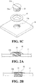
- FIG. 1C is an exploded perspective view of frequency tuning components of FIG. 1A .
- the cavity-type radio frequency filter according to the first embodiment has an enclosure 21 having a hollow inside and at least one cavity blocked from outside, similar to a conventional radio frequency filter.
- the enclosure 21 forming a cavity has one open side (e.g., open top side).
- a cover 11 is fixedly coupled to the enclosure 21 for sealing thereof.
- a resonant element 51 is fixedly installed on the bottom surface of the enclosure 21.
- FIGS. 1A to 1C illustrate the enclosure 21 as having, for example, a single-cavity structure.
- the enclosure 21 may be configured to have a plurality of cavities connected in multiple stages, and each cavity may have a resonant element at its center.
- an input terminal and an output terminal of the radio frequency filter may be formed at one side and the other side of the enclosure 21.
- the input terminal and output terminal may be attached to the enclosure 21 so as to be connected to the input end cavity structure and the output end cavity structure, respectively.
- the enclosure 21, the cavity structure formed by the enclosure 21, and the structure of the resonant element 51 may be configured similar to the conventional ones, and both the enclosure 21 and the resonant element 51 may be made of aluminum-based (alloy) material.
- the cover 11 according to at least one embodiment of the present disclosure may be made of the same material as that of the enclosure 21, that is, aluminum-based material, similar to the conventional art.
- the surface of cavity-forming portions of the enclosure 21 and the cover 11 may be silver plated.
- the cover 11 is formed with a screw hole 11a of a preset diameter to penetrate the cover 11 at a portion corresponding to the resonant element 51 in the cavity of the enclosure 21.
- the side surface of the screw hole 11a may be formed with a threaded coupling structure for coupling with a frequency tuning screw 31 for frequency tuning.
- the screw hole 11a generally has an internally threaded structure for allowing the frequency tuning screw 31 to be coupled in a threaded manner.
- the frequency tuning screw 31 is threadedly fastened to the screw hole 11a, and has its lower end penetrate into the cavity of the enclosure 21 through the screw hole 11a.
- the frequency tuning screw 31 has at its side a male screw thread to be screwed into the screw hole 11a, and has an appropriately shaped top (or head) drive groove 31b for engaging drive equipment (driver, wrench, etc.) to perform screw tightening operation.
- the driving groove 31b is illustrated as being slotted, but may have various shapes such as a cross shape and a hexagonal groove.
- the frequency tuning screw 31 may be made of a forging material such as brass (alloy), it may be silver plated on the surface.
- the latching abutment 31a may be made by providing the upper end of the frequency tuning screw 31 with a generally enlarged diameter relative to the other part (i.e., the shank).
- the frequency tuning screw 31 is fitted into a ring-shaped resilient fixing member 41 and then coupled to the screw hole 11a of the cover 11.
- the ring-shaped resilient fixing member 41 is caught by the latching abutment 31a of the frequency tuning screw 31 and is latched in position between the latching abutment 31a of the frequency tuning screw 31 and the upper surface of the cover 11.
- the resilient fixing member 41 is formed with a thin plate generally having a ring shape (for example, a hollowed out donut shape), and is generally tapered in cross section with a lower outer diameter narrowing into an upper inner diameter toward the hollow portion.
- the resilient fixing member 41 is made of a material such as SUS to have a predetermined resilience and an appropriate strength.
- the hollow portion of the resilient fixing member 41 is formed to have a diameter with a margin, which is slightly larger than the diameter of the shank of the frequency tuning screw 31 but smaller than the upper end of the frequency tuning screw 31 inclusive of the latching abutment 31a.
- the frequency tuning screw 31 in the frequency tuning operation is coupled and tightened to the screw hole 11a of the cover 11 via the resilient fixing member 41.
- the latching abutment 31a of the frequency tuning screw 31 when tightened presses the resilient fixing member 41. Accordingly, as shown more clearly in FIG. 1B , the resilient fixing member 41 exerts a spring force on the frequency tuning screw 31 through the latching abutment 31a, whereby the frequency tuning screw 31 stays tightened.
- the frequency tuning screw 31 As the frequency tuning screw 31 is tightened, the lower end of the frequency tuning screw 31 is pushed toward the resonant element 51 inside the cavity, and the gap is reduced between the lower end of the frequency tuning screw 31 and the resonant element 51. As a result, the capacitance is adjusted between the frequency tuning screw 31 and the resonant element 51 to in turn adjust the characteristics of the corresponding filtering frequency.
- the resilient fixing member 41 retains some resiliency, the frequency characteristics can be tuned by repeatedly tightening or loosening the frequency tuning screw 31, and at the same time as the frequency characteristic tuning operation, the resilient fixing member 41 maintains and fixates the current state of the frequency tuning screw 31.
- FIG. 2A is a cutaway diagram of frequency tuning parts in a cavity-type radio frequency filter according to a second embodiment of the present disclosure.
- FIG. 2B is a diagram of a frequency tuning screw of FIG. 2A in an illustrative fixed position, e.g., where the frequency tuning screw is tightened.
- FIG. 2C is a perspective view of the frequency tuning screw of FIG. 2A .
- the radio frequency filter according to the second embodiment of the present disclosure includes an enclosure (not shown), a cover 11, and others as with the first embodiment, except some differences in the frequency tuning structure.
- At least a portion of the upper end of a frequency tuning screw 31 according to the second embodiment is formed with a resilient fixing member 32 of a material having a predetermined spring force. At least a portion of the resilient fixing member 32 is formed with a resilient protrusion 32a configured to protrude externally and obliquely to the lower end.
- the resilient protrusion 32a of the resilient fixing member 32 may be formed all around the edge at the upper end (head portion) of the frequency tuning screw 31, and is generally tapered in cross section.
- the frequency tuning screw 31 has a shank which may be implemented by a forging material such as brass, and the resilient fixing member 32 inclusive of the resilient protrusion 32a may be implemented by a thin metal plate by a material such as SUS, which is then attached to the shank of the frequency tuning screw 31 by laser welding or the like.
- a forging material such as brass
- the resilient fixing member 32 inclusive of the resilient protrusion 32a may be implemented by a thin metal plate by a material such as SUS, which is then attached to the shank of the frequency tuning screw 31 by laser welding or the like.
- the frequency tuning screw 31 combined with the resilient fixing member 32 is coupled to a cover 11 at a screw hole (e.g., 11a of FIG. 1C ).
- a screw hole e.g., 11a of FIG. 1C
- the resilient protrusion 32a of the resilient fixing member 32 combined with the frequency tuning screw 31 at its head is pressed against the upper surface of the cover 11. Accordingly, the frequency tuning screw 31 remains tightened by the spring force of the resilient protrusion 32a.
- the frequency characteristics can be tuned by repeatedly tightening or loosening the frequency tuning screw 31.
- FIG. 3A is a cutaway diagram of frequency tuning parts in a cavity-type radio frequency filter according to a third embodiment of the present disclosure.
- FIG. 3B is a perspective view of a resilient fixing member of FIG. 3A .
- a cover 12 is provided with a screw hole having an upper end formed at at least a part thereof with a latching abutment 12a as an overhang.
- the latching abutment 12a may be formed by having a diameter generally narrower than the rest of the screw hole.
- the frequency tuning screw 33 is formed to have a generally constant diameter so as to be coupled to the screw hole of the cover 12.
- the frequency tuning screw 33 is preinstalled in partial engagement with the screw hole of the cover 12 from inside of a cavity (i.e., under the cover) of an enclosure (not shown). Once the cover is coupled to the enclosure, the external driver equipment engages the frequency tuning screw 33 through a drive groove (not shown) prepared on the upper end thereof to perform the tightening operation of the frequency tuning screw 33.
- a ring-shaped resilient fixing member 42 according to the third embodiment of the present disclosure is installed in the screw hole of the cover 12 so as to be located between the latching abutment 12a and the frequency tuning screw 33.
- the ring-shaped resilient fixing member 42 is caught by the latching abutment 12a of the cover 12, so that the frequency tuning screw 33 is subject to an application of spring force.
- the resilient fixing member 42 is generally composed of a thin plate havings a ring shape (e.g., a hollowed-out donut shape), and is generally tapered in cross section with an upper outer diameter narrowing into a lower inner diameter toward the hollow portion.
- the resilient fixing member 42 according to the third embodiment is turned upside down into an inverse structure of that of the first embodiment.
- the resilient fixing member 42 is made of a material such as SUS to have a predetermined spring force and an appropriate strength.
- the latching abutment 12a of the cover 12 depresses the resilient fixing member 42. Accordingly, the resilient fixing member 42 exerts a spring force on the frequency tuning screw 33, thereby keeping the frequency tuning screw 33 in the current tightened state.
- the frequency characteristics can be tuned by repeatedly tightening or loosening the frequency tuning screw 33.
- FIG. 4A is a cutaway diagram of frequency tuning parts in a cavity-type radio frequency filter according to a fourth embodiment of the present disclosure.
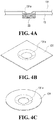
- FIG. 4B is a perspective view of an example shape of resilient fixing member of FIG. 4A.
- FIG. 4C is a perspective view of another example shape of the resilient fixing member of FIG. 4A .
- a cover 13 is provided with a screw hole and a resilient fixing member 131 attached to the cover 13 and extending around at least part of the screw hole.
- FIG. 4B shows an example in which the resilient fixing member 131 is formed in a plate shape having a generally rectangular planar structure
- FIG. 4C illustrates the resilient fixing member 131 as having a generally circular planar structure.
- the resilient protrusion 131a may be formed all around the screw hole of the cover 13, and it is generally tapered in cross section with an upper outer diameter narrowing into a lower inner diameter toward the hollow portion.
- the cover 13 may be made of an aluminum (alloy) material, and the resilient fixing member 131 inclusive of the resilient protrusion 131a may be implemented by a thin metal plate with a material such as SUS, which is then attached to the upper portion of the cover 13 at positions corresponding to the screw hole by laser welding or the like. At this time, the frequency tuning screw 33 is formed to have a generally constant diameter so that it may be coupled to the screw hole of the cover 13.
- the frequency tuning screw 33 is similar to the third embodiment shown in FIG. 3A above in that it is preinstalled in partial engagement with the screw hole of the cover 13 from inside of a cavity (i.e., under the cover) of an enclosure (not shown). Once the cover is coupled to the enclosure, the external driver equipment engages the frequency tuning screw 33 through a drive groove (not shown) prepared on the upper end thereof to perform the tightening operation of the frequency tuning screw 33.
- the frequency tuning screw 33 is coupled to the screw hole of the cover 13 and then tightened toward the resilient protrusion 131a of the resilient fixing member 131.
- the resilient protrusion 131a of the resilient fixing member 131 is pressed against the upper surface of the frequency tuning screw 33. Accordingly, the frequency tuning screw 33 is maintained in the current tightened state by the resilient force of the resilient protrusion 131a.
- the frequency characteristics can be tuned by repeatedly tightening or loosening the frequency tuning screw 33.
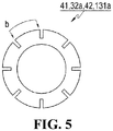
- FIG. 5 is a plan view of another modified structure of a main part of resilient fixing members according to embodiments of the present disclosure.
- the structure of FIG. 5 may be the resilient fixing member 41 according to the first embodiment of FIGS. 1A to 1C as shown in plan view or the resilient fixing member 42 according to the third embodiment of FIGS. 3A and 3B as shown in plan view.
- the structure of FIG. 5 may be the resilient protrusion 32a of the resilient fixing member 32 according to the second embodiment of FIG. 2A to FIG. 2C as shown in plan view or the resilient protrusion 131a of the resilient fixing member 131 according to the fourth embodiment of FIGS. 4A to 4C as shown in plan view.
- the resilient fixing members 41 and 42 or the resilient protrusions 32a and 131a of the resilient fixing members may be provided with a plurality of grooves b which may be, for example, inward slits extending some distance from the periphery.
- the plurality of grooves b may serve to increase the spring force or the restoring force of the resilient fixing members 41 and 42 or the resilient protrusions 32a and 131a of the resilient fixing members.
- the diameter or length of the plurality of grooves b or other specific detailed structures may be variously designed.
- a cavity-type radio frequency filter may be configured according to embodiments of the present disclosure.
- the present disclosure encompasses other various embodiments or modifications.
- the resonant elements may be made as separate components to be attached to the internal floor of the enclosure of the radio frequency filter. Since the enclosure and the resonant element may be made of the same material, they can be integrally formed by a die casting method. Alternatively, as in the technique disclosed by the above-mentioned Patent Application Publication No. 10-2014-0026235 , the enclosure and its internal resonant elements may be integrally formed by a pressing process as a whole.
Landscapes
- Physics & Mathematics (AREA)
- Electromagnetism (AREA)
- Engineering & Computer Science (AREA)
- Manufacturing & Machinery (AREA)
- Control Of Motors That Do Not Use Commutators (AREA)
Abstract
Description
- The present disclosure in some embodiments relates to a radio signal processing apparatus for use in a wireless communication system. More particularly, the present disclosure relates to a cavity-type radio frequency filter (hereinafter, abbreviated as 'filter'), such as a cavity filter.
- A radio frequency filter having a cavity structure generally utilizes a metallic enclosure for providing a plurality of accommodation spaces or cavities having a shape such as rectangular parallelepiped and the like, in which dielectric resonant elements (DR) or resonant elements composed of a metallic resonance rod are each provided for generating superhigh frequency resonance. Further, such cavity-type radio frequency filter is generally provided at its upper portion with a cover for shielding the open areas of the corresponding cavities, where the cover may have, as a configuration for tuning the filtering characteristic of the radio frequency filter, a plurality of tuning screws and nuts for fixing the corresponding tuning screws. An example cavity-type radio frequency filter is disclosed by Korean Patent Application Publication No.
10-2004-100084 - Those cavity-type radio frequency filters are used for processing radio transmit and receive signals in a radio communication system. Particularly in mobile communication systems, the cavity-type radio frequency filters are typically used for base stations, repeaters or relays and the like.
- Meanwhile, Korean Patent Application Publication No.
10-2014-0026235 10-2014-0026235 - The technique disclosed by the above-mentioned Patent Application Publication No.
10-2014-0026235 - However, the technique disclosed by the above-mentioned Patent Application Publication No.
10-2014-0026235 - Accordingly, the present disclosure in some embodiments seeks to provide a simpler cavity-type radio frequency filter which is simpler, more compact and lighter, and which enables simpler manufacturing operation with lower cost. In particular, the cavity-type radio frequency filter according to at least some embodiments of the present disclosure has a frequency tuning structure that can reversibly perform the frequency tuning operation, thereby making the tuning operation more efficient and easier.
- At least one embodiment of the present disclosure provides a radio frequency filter having a cavity structure including an enclosure, a resonant element, a cover, a frequency tuning screw, and a resilient fixing member. The enclosure has a hollow inside and an open surface on one side to have a cavity. The resonant element is positioned in the hollow of the enclosure. The cover has a screw hole having a preset diameter at a position corresponding to the resonant element, and is configured to seal the open surface of the enclosure. The frequency tuning screw is configured to be screwed into the screw hole of the cover, and it has an upper end formed at least partially with a latching abutment that protrudes outwardly. The resilient fixing member is configured to be caught on the latching abutment of the frequency tuning screw and coupled between the frequency tuning screw and the cover, to be annular and planar in shape having a hollow portion, and to be generally tapered in cross section with a lower outer diameter narrowing into an upper inner diameter toward the hollow portion, and to have a predetermined spring force.
- Another embodiment of the present disclosure provides a radio frequency filter having a cavity structure including an enclosure, a resonant element, a cover, and a frequency tuning screw. The enclosure has a hollow inside and an open surface on one side to have a cavity. The resonant element is positioned in the hollow of the enclosure. The cover has a screw hole having a preset diameter at a position corresponding to the resonant element, and it is configured to seal the open surface of the enclosure. The frequency tuning screw is configured to be screwed into the screw hole of the cover. The frequency tuning screw has an upper end formed at least partially with a resilient fixing member having a predetermined spring force, and the resilient fixing member is formed at least partially with a resilient protrusion configured to protrude obliquely outwardly toward a lower end of the frequency tuning screw.
- Yet another embodiment of the present disclosure provides a radio frequency filter having a cavity structure including an enclosure, a resonant element, a cover, a frequency tuning screw, and a resilient fixing member. The enclosure has a hollow inside and an open surface on one side to have a cavity. The resonant element is positioned in the hollow of the enclosure. The cover is configured to seal the open surface of the enclosure, to provide a screw hole with a preset diameter at a position corresponding to the resonant element, and to have an upper end formed at least partially with a latching abutment as an overhang. The frequency tuning screw is configured to be screwed into the screw hole of the cover. The resilient fixing member is configured to be caught in the screw hole of the cover on the latching abutment and latched between the frequency tuning screw and the latching abutment, to be annular and planar in shape having a hollow portion, to be generally tapered in cross section with an upper outer diameter narrowing into a lower inner diameter toward the hollow portion, and to have a predetermined spring force.
- Yet another embodiment of the present disclosure provides a radio frequency filter having a cavity structure including an enclosure, a resonant element, a cover, and a frequency tuning screw. The enclosure has a hollow inside and an open surface on one side to have a cavity. The resonant element is positioned in the hollow of the enclosure. The cover has a screw hole having a preset diameter at a position corresponding to the resonant element, and configured to seal the open surface of the enclosure. The frequency tuning screw is configured to be screwed into the screw hole of the cover. The cover is formed around the screw hole at least partially with a resilient fixing member having a predetermined spring force and attached to the cover, and the resilient fixing member is formed at least partially with a resilient protrusion configured to protrude downwardly and obliquely inwardly of the screw hole.
- As described above, the cavity-type radio frequency filter according to some embodiments of the present disclosure is structured for allowing the frequency tuning operation to be performed reversibly without employing a conventional coupling structure of fastening nuts, which are required when installing conventional frequency tuning screws. The resulting radio frequency filter is more compact and lighter.
-
-
FIG. 1A is a diagram of a cutaway structure of a cavity-type radio frequency filter according to a first embodiment of the present disclosure. -
FIG. 1B is a diagram of the frequency tuning screw ofFIG. 1A in an illustrative fixed position. -
FIG. 1C is an exploded perspective view of frequency tuning components ofFIG. 1A . -
FIG. 2A is a cutaway diagram of frequency tuning parts in a cavity-type radio frequency filter according to a second embodiment of the present disclosure. -
FIG. 2B is a diagram of a frequency tuning screw ofFIG. 2A in an illustrative fixed position. -
FIG. 2C is a perspective view of the frequency tuning screw ofFIG. 2A . -
FIG. 3A is a cutaway diagram of frequency tuning parts in a cavity-type radio frequency filter according to a third embodiment of the present disclosure. -
FIG. 3B is a perspective view of a resilient fixing member ofFIG. 3A . -
FIG. 4A is a cutaway diagram of frequency tuning parts in a cavity-type radio frequency filter according to a fourth embodiment of the present disclosure. -
FIG. 4B is a perspective view of an example shape of resilient fixing member ofFIG. 4A . -
FIG. 4C is a perspective view of another example shape of the resilient fixing member ofFIG. 4A . -
FIG. 5 is a plan view of another modified structure of a main part of resilient fixing members according to embodiments of the present disclosure. - Hereinafter, exemplary embodiments of the present disclosure will be described in detail with reference to the accompanying drawings. In the drawings, like reference numerals refer to like elements as much as possible, and for the convenience of description, the size, shape, and the like are somewhat simplified or partially exaggerated.
-
FIG. 1A is a diagram of a cutaway structure of a cavity-type radio frequency filter according to a first embodiment of the present disclosure.FIG. 1B is a diagram of the frequency tuning screw ofFIG. 1A in an illustrative fixed position, e.g., where the frequency tuning screw is tightened.FIG. 1C is an exploded perspective view of frequency tuning components ofFIG. 1A . As shown inFIGS. 1A to 1C , the cavity-type radio frequency filter according to the first embodiment has anenclosure 21 having a hollow inside and at least one cavity blocked from outside, similar to a conventional radio frequency filter. Theenclosure 21 forming a cavity has one open side (e.g., open top side). In addition, configured to cover the open side of theenclosure 21, acover 11 is fixedly coupled to theenclosure 21 for sealing thereof. Centrally of the cavity formed in theenclosure 21, aresonant element 51 is fixedly installed on the bottom surface of theenclosure 21. - For convenience of description,
FIGS. 1A to 1C illustrate theenclosure 21 as having, for example, a single-cavity structure. However, in addition to such a structure, theenclosure 21 may be configured to have a plurality of cavities connected in multiple stages, and each cavity may have a resonant element at its center. In addition, although not shown inFIGS. 1A to 1C , an input terminal and an output terminal of the radio frequency filter may be formed at one side and the other side of theenclosure 21. When theenclosure 21 is configured to have a plurality of cavities, the input terminal and output terminal may be attached to theenclosure 21 so as to be connected to the input end cavity structure and the output end cavity structure, respectively. - In the above-described configuration, the
enclosure 21, the cavity structure formed by theenclosure 21, and the structure of theresonant element 51 may be configured similar to the conventional ones, and both theenclosure 21 and theresonant element 51 may be made of aluminum-based (alloy) material. In addition, thecover 11 according to at least one embodiment of the present disclosure may be made of the same material as that of theenclosure 21, that is, aluminum-based material, similar to the conventional art. In addition, the surface of cavity-forming portions of theenclosure 21 and thecover 11 may be silver plated. - The focus now turns to a frequency tuning configuration for the radio frequency filter having the above-described structure according to the first embodiment of the present disclosure. The
cover 11 is formed with ascrew hole 11a of a preset diameter to penetrate thecover 11 at a portion corresponding to theresonant element 51 in the cavity of theenclosure 21. The side surface of thescrew hole 11a may be formed with a threaded coupling structure for coupling with afrequency tuning screw 31 for frequency tuning. In other words, thescrew hole 11a generally has an internally threaded structure for allowing thefrequency tuning screw 31 to be coupled in a threaded manner. - The
frequency tuning screw 31 is threadedly fastened to thescrew hole 11a, and has its lower end penetrate into the cavity of theenclosure 21 through thescrew hole 11a. Thefrequency tuning screw 31 has at its side a male screw thread to be screwed into thescrew hole 11a, and has an appropriately shaped top (or head)drive groove 31b for engaging drive equipment (driver, wrench, etc.) to perform screw tightening operation. In the example ofFIG. 1C , the drivinggroove 31b is illustrated as being slotted, but may have various shapes such as a cross shape and a hexagonal groove. Thefrequency tuning screw 31 may be made of a forging material such as brass (alloy), it may be silver plated on the surface. - At least a portion of the upper end (head) of the
frequency tuning screw 31 protrudes externally to form a latchingabutment 31a according to the first embodiment of the present disclosure. The latchingabutment 31a may be made by providing the upper end of thefrequency tuning screw 31 with a generally enlarged diameter relative to the other part (i.e., the shank). - In addition, the
frequency tuning screw 31 is fitted into a ring-shaped resilient fixingmember 41 and then coupled to thescrew hole 11a of thecover 11. As thefrequency tuning screw 31 is tightened, the ring-shaped resilient fixingmember 41 is caught by the latchingabutment 31a of thefrequency tuning screw 31 and is latched in position between the latchingabutment 31a of thefrequency tuning screw 31 and the upper surface of thecover 11. - The resilient fixing
member 41 according to the first embodiment of the present disclosure is formed with a thin plate generally having a ring shape (for example, a hollowed out donut shape), and is generally tapered in cross section with a lower outer diameter narrowing into an upper inner diameter toward the hollow portion. In addition, the resilient fixingmember 41 is made of a material such as SUS to have a predetermined resilience and an appropriate strength. The hollow portion of the resilient fixingmember 41 is formed to have a diameter with a margin, which is slightly larger than the diameter of the shank of thefrequency tuning screw 31 but smaller than the upper end of thefrequency tuning screw 31 inclusive of the latchingabutment 31a. - With the aforementioned filter structure, the
frequency tuning screw 31 in the frequency tuning operation is coupled and tightened to thescrew hole 11a of thecover 11 via the resilient fixingmember 41. The latchingabutment 31a of thefrequency tuning screw 31 when tightened presses the resilient fixingmember 41. Accordingly, as shown more clearly inFIG. 1B , the resilient fixingmember 41 exerts a spring force on thefrequency tuning screw 31 through the latchingabutment 31a, whereby thefrequency tuning screw 31 stays tightened. - As the
frequency tuning screw 31 is tightened, the lower end of thefrequency tuning screw 31 is pushed toward theresonant element 51 inside the cavity, and the gap is reduced between the lower end of thefrequency tuning screw 31 and theresonant element 51. As a result, the capacitance is adjusted between thefrequency tuning screw 31 and theresonant element 51 to in turn adjust the characteristics of the corresponding filtering frequency. - At this time, since the resilient fixing
member 41 retains some resiliency, the frequency characteristics can be tuned by repeatedly tightening or loosening thefrequency tuning screw 31, and at the same time as the frequency characteristic tuning operation, the resilient fixingmember 41 maintains and fixates the current state of thefrequency tuning screw 31. -
FIG. 2A is a cutaway diagram of frequency tuning parts in a cavity-type radio frequency filter according to a second embodiment of the present disclosure.FIG. 2B is a diagram of a frequency tuning screw ofFIG. 2A in an illustrative fixed position, e.g., where the frequency tuning screw is tightened.FIG. 2C is a perspective view of the frequency tuning screw ofFIG. 2A . As shown inFIGS. 2A to 2C , the radio frequency filter according to the second embodiment of the present disclosure includes an enclosure (not shown), acover 11, and others as with the first embodiment, except some differences in the frequency tuning structure. - At least a portion of the upper end of a
frequency tuning screw 31 according to the second embodiment is formed with a resilient fixingmember 32 of a material having a predetermined spring force. At least a portion of the resilient fixingmember 32 is formed with aresilient protrusion 32a configured to protrude externally and obliquely to the lower end. Theresilient protrusion 32a of the resilient fixingmember 32 may be formed all around the edge at the upper end (head portion) of thefrequency tuning screw 31, and is generally tapered in cross section. - The
frequency tuning screw 31 has a shank which may be implemented by a forging material such as brass, and the resilient fixingmember 32 inclusive of theresilient protrusion 32a may be implemented by a thin metal plate by a material such as SUS, which is then attached to the shank of thefrequency tuning screw 31 by laser welding or the like. - In the filter structure as described above, during the frequency tuning operation, the
frequency tuning screw 31 combined with the resilient fixingmember 32 is coupled to acover 11 at a screw hole (e.g., 11a ofFIG. 1C ). As thefrequency tuning screw 31 is tightened, as shown more clearly inFIG. 2B , theresilient protrusion 32a of the resilient fixingmember 32 combined with thefrequency tuning screw 31 at its head is pressed against the upper surface of thecover 11. Accordingly, thefrequency tuning screw 31 remains tightened by the spring force of theresilient protrusion 32a. - At this time, since the
resilient protrusion 32a retains some resiliency, the frequency characteristics can be tuned by repeatedly tightening or loosening thefrequency tuning screw 31. -
FIG. 3A is a cutaway diagram of frequency tuning parts in a cavity-type radio frequency filter according to a third embodiment of the present disclosure.FIG. 3B is a perspective view of a resilient fixing member ofFIG. 3A . As shown inFIGS. 3A and 3B , the frequency tuning structure of the radio frequency filter according to the third embodiment of the present disclosure is described. In the third embodiment, acover 12 is provided with a screw hole having an upper end formed at at least a part thereof with a latchingabutment 12a as an overhang. The latchingabutment 12a may be formed by having a diameter generally narrower than the rest of the screw hole. In addition, thefrequency tuning screw 33 is formed to have a generally constant diameter so as to be coupled to the screw hole of thecover 12. - In the embodiment shown in
FIG. 3A , thefrequency tuning screw 33 is preinstalled in partial engagement with the screw hole of thecover 12 from inside of a cavity (i.e., under the cover) of an enclosure (not shown). Once the cover is coupled to the enclosure, the external driver equipment engages thefrequency tuning screw 33 through a drive groove (not shown) prepared on the upper end thereof to perform the tightening operation of thefrequency tuning screw 33. - At this time, a ring-shaped resilient fixing
member 42 according to the third embodiment of the present disclosure is installed in the screw hole of thecover 12 so as to be located between the latchingabutment 12a and thefrequency tuning screw 33. As thefrequency tuning screw 33 is tightened toward the resilient fixingmember 42, the ring-shaped resilient fixingmember 42 is caught by the latchingabutment 12a of thecover 12, so that thefrequency tuning screw 33 is subject to an application of spring force. - Similar to the structure of the first embodiment, the resilient fixing
member 42 is generally composed of a thin plate havings a ring shape (e.g., a hollowed-out donut shape), and is generally tapered in cross section with an upper outer diameter narrowing into a lower inner diameter toward the hollow portion. In other words, the resilient fixingmember 42 according to the third embodiment is turned upside down into an inverse structure of that of the first embodiment. In addition, the resilient fixingmember 42 is made of a material such as SUS to have a predetermined spring force and an appropriate strength. - In the third embodiment, when the
frequency tuning screw 33 is tightened for frequency tuning with the resilient fixingmember 42 interposed in the screw hole of thecover 12, the latchingabutment 12a of thecover 12 depresses the resilient fixingmember 42. Accordingly, the resilient fixingmember 42 exerts a spring force on thefrequency tuning screw 33, thereby keeping thefrequency tuning screw 33 in the current tightened state. As with the previous embodiments, the frequency characteristics can be tuned by repeatedly tightening or loosening thefrequency tuning screw 33. -
FIG. 4A is a cutaway diagram of frequency tuning parts in a cavity-type radio frequency filter according to a fourth embodiment of the present disclosure.FIG. 4B is a perspective view of an example shape of resilient fixing member ofFIG. 4A. FIG. 4C is a perspective view of another example shape of the resilient fixing member ofFIG. 4A . Referring toFIGS. 4A to 4C , the frequency tuning structure of the radio frequency filter according to the fourth embodiment of the present disclosure will be described. In the fourth embodiment, acover 13 is provided with a screw hole and a resilient fixingmember 131 attached to thecover 13 and extending around at least part of the screw hole.FIG. 4B shows an example in which the resilient fixingmember 131 is formed in a plate shape having a generally rectangular planar structure, andFIG. 4C illustrates the resilient fixingmember 131 as having a generally circular planar structure. - of the resilient fixing
member 131 is formed with aresilient protrusion 131a configured to be obliquely projected downward into the screw hole of thecover 13. Theresilient protrusion 131a may be formed all around the screw hole of thecover 13, and it is generally tapered in cross section with an upper outer diameter narrowing into a lower inner diameter toward the hollow portion. - The
cover 13 may be made of an aluminum (alloy) material, and the resilient fixingmember 131 inclusive of theresilient protrusion 131a may be implemented by a thin metal plate with a material such as SUS, which is then attached to the upper portion of thecover 13 at positions corresponding to the screw hole by laser welding or the like. At this time, thefrequency tuning screw 33 is formed to have a generally constant diameter so that it may be coupled to the screw hole of thecover 13. - In the embodiment shown in
FIGS. 4A to 4C , thefrequency tuning screw 33 is similar to the third embodiment shown inFIG. 3A above in that it is preinstalled in partial engagement with the screw hole of thecover 13 from inside of a cavity (i.e., under the cover) of an enclosure (not shown). Once the cover is coupled to the enclosure, the external driver equipment engages thefrequency tuning screw 33 through a drive groove (not shown) prepared on the upper end thereof to perform the tightening operation of thefrequency tuning screw 33. - In the filter structure as described above, during the frequency tuning operation, the
frequency tuning screw 33 is coupled to the screw hole of thecover 13 and then tightened toward theresilient protrusion 131a of the resilient fixingmember 131. As thescrew 33 is tightened, theresilient protrusion 131a of the resilient fixingmember 131 is pressed against the upper surface of thefrequency tuning screw 33. Accordingly, thefrequency tuning screw 33 is maintained in the current tightened state by the resilient force of theresilient protrusion 131a. As with the previous embodiments, the frequency characteristics can be tuned by repeatedly tightening or loosening thefrequency tuning screw 33. -
FIG. 5 is a plan view of another modified structure of a main part of resilient fixing members according to embodiments of the present disclosure. The structure ofFIG. 5 may be the resilient fixingmember 41 according to the first embodiment ofFIGS. 1A to 1C as shown in plan view or the resilient fixingmember 42 according to the third embodiment ofFIGS. 3A and 3B as shown in plan view. Alternatively, the structure ofFIG. 5 may be theresilient protrusion 32a of the resilient fixingmember 32 according to the second embodiment ofFIG. 2A to FIG. 2C as shown in plan view or theresilient protrusion 131a of the resilient fixingmember 131 according to the fourth embodiment ofFIGS. 4A to 4C as shown in plan view. - As shown in
FIG. 5 , theresilient fixing members resilient protrusions resilient fixing members resilient protrusions - As described above, a cavity-type radio frequency filter may be configured according to embodiments of the present disclosure. The present disclosure encompasses other various embodiments or modifications. For example, the resonant elements may be made as separate components to be attached to the internal floor of the enclosure of the radio frequency filter. Since the enclosure and the resonant element may be made of the same material, they can be integrally formed by a die casting method. Alternatively, as in the technique disclosed by the above-mentioned Patent Application Publication No.
10-2014-0026235 - It should be understood that the detailed structure, size, etc. of specific detailed components such as frequency tuning screws, grooves, through holes, etc., as well as the number and shape of cavities provided in the enclosure may be variously changed.
- Therefore, various modifications and variations of the present disclosure can be made without departing from the idea and scope of the present disclosure as defined by the appended claims and their equivalents rather than the particularly illustrated embodiments.
Claims (8)
- A radio frequency filter having a cavity structure, comprising:an enclosure having a hollow inside and having an open surface on one side to have a cavity;a resonant element positioned in the hollow of the enclosure;a cover having a screw hole having a preset diameter at a position corresponding to the resonant element, and configured to seal the open surface of the enclosure;a frequency tuning screw configured to be screwed into the screw hole of the cover, and having an upper end formed at least partially with a latching abutment that protrudes outwardly; anda resilient fixing member configuredto be caught on the latching abutment of the frequency tuning screw and coupled between the frequency tuning screw and the cover,to be annular and planar in shape having a hollow portion, andto be generally tapered in cross section with a lower outer diameter narrowing into an upper inner diameter toward the hollow portion, andto have a predetermined spring force.
- A radio frequency filter having a cavity structure, comprising:an enclosure having a hollow inside and having an open surface on one side to have a cavity;a resonant element positioned in the hollow of the enclosure;a cover having a screw hole having a preset diameter at a position corresponding to the resonant element, and configured to seal the open surface of the enclosure; anda frequency tuning screw configured to be screwed into the screw hole of the cover,wherein the frequency tuning screw has an upper end formed at least partially with a resilient fixing member having a predetermined spring force, andwherein the resilient fixing member is formed at least partially with a resilient protrusion configured to protrude obliquely outwardly toward a lower end of the frequency tuning screw.
- The radio frequency filter of claim 2, wherein the resilient protrusion of the resilient fixing member is formed all around an upper edge of the frequency tuning screw and is generally tapered in cross section.
- A radio frequency filter having a cavity structure, comprising:an enclosure having a hollow inside and having an open surface on one side to have a cavity;a resonant element positioned in the hollow of the enclosure;a cover configuredto seal the open surface of the enclosure,to provide a screw hole with a preset diameter at a position corresponding to the resonant element, andto have an upper end formed at least partially with a latching abutment as an overhang;a frequency tuning screw configured to be screwed into the screw hole of the cover; anda resilient fixing member configuredto be caught in the screw hole of the cover on the latching abutment and latched between the frequency tuning screw and the latching abutment,to be annular and planar in shape having a hollow portion,to be generally tapered in cross section with an upper outer diameter narrowing into a lower inner diameter toward the hollow portion, andto have a predetermined spring force.
- A radio frequency filter having a cavity structure, comprising:an enclosure having a hollow inside and having an open surface on one side to have a cavity;a resonant element positioned in the hollow of the enclosure;a cover having a screw hole having a preset diameter at a position corresponding to the resonant element, and configured to seal the open surface of the enclosure; anda frequency tuning screw configured to be screwed into the screw hole of the cover,wherein the cover is formed around the screw hole at least partially with a resilient fixing member having a predetermined spring force and attached to the cover, andwherein the resilient fixing member is formed at least partially with a resilient protrusion configured to protrude downwardly and obliquely inwardly of the screw hole.
- The radio frequency filter of claim 5, wherein the resilient protrusion of the resilient fixing member is formed all around the screw hole of the cover and is generally tapered in cross section.
- The radio frequency filter of claim 1 or 4, wherein the resilient fixing member has a plurality of grooves which are inward slits extending from a periphery of the resilient fixing member.
- The radio frequency filter of any one of claims 2,, 3, 5 and 6, wherein the resilient protrusion of the resilient fixing member has a plurality of grooves which are inward slits extending from a periphery of the resilient protrusion.
Applications Claiming Priority (2)
| Application Number | Priority Date | Filing Date | Title |
|---|---|---|---|
| KR20170056359 | 2017-05-02 | ||
| PCT/KR2018/005080 WO2018203655A1 (en) | 2017-05-02 | 2018-05-02 | Cavity-type radio frequency filter |
Publications (3)
| Publication Number | Publication Date |
|---|---|
| EP3621145A1 true EP3621145A1 (en) | 2020-03-11 |
| EP3621145A4 EP3621145A4 (en) | 2021-01-06 |
| EP3621145B1 EP3621145B1 (en) | 2024-07-10 |
Family
ID=64016217
Family Applications (1)
| Application Number | Title | Priority Date | Filing Date |
|---|---|---|---|
| EP18794866.6A Active EP3621145B1 (en) | 2017-05-02 | 2018-05-02 | Cavity-type radio frequency filter |
Country Status (7)
| Country | Link |
|---|---|
| US (1) | US11108121B2 (en) |
| EP (1) | EP3621145B1 (en) |
| JP (1) | JP6934107B2 (en) |
| KR (2) | KR20220101777A (en) |
| CN (1) | CN110574222B (en) |
| FI (1) | FI3621145T3 (en) |
| WO (1) | WO2018203655A1 (en) |
Families Citing this family (2)
| Publication number | Priority date | Publication date | Assignee | Title |
|---|---|---|---|---|
| WO2022045754A1 (en) * | 2020-08-28 | 2022-03-03 | 주식회사 케이엠더블유 | Cavity filter for antenna |
| CN113346215B (en) * | 2021-06-29 | 2026-01-16 | 大富科技(安徽)股份有限公司 | Resonator, filter, duplexer, multiplexer and communication equipment |
Family Cites Families (24)
| Publication number | Priority date | Publication date | Assignee | Title |
|---|---|---|---|---|
| FR2477782A1 (en) * | 1980-03-05 | 1981-09-11 | Thomson Csf | HYPERFREQUENCY TUNING DEVICE OF THE SLIDING CONTACTS TYPE AND FILTER COMPRISING SUCH A DEVICE |
| FR2649538B1 (en) * | 1989-07-10 | 1991-12-13 | Alcatel Transmission | MICROWAVE ADJUSTMENT BOX |
| JPH0464816U (en) * | 1990-10-15 | 1992-06-04 | ||
| JPH098512A (en) * | 1995-06-16 | 1997-01-10 | Nec Eng Ltd | Waveguide crossing type directional coupler |
| SE519554C2 (en) * | 1999-04-14 | 2003-03-11 | Ericsson Telefon Ab L M | Screw device and trim device comprising such a screw device for trimming the frequency ratio or degree of coupling of a cavity filter |
| US6222428B1 (en) * | 1999-06-15 | 2001-04-24 | Allgon Ab | Tuning assembly for a dielectrical resonator in a cavity |
| CN1571214A (en) * | 2000-05-23 | 2005-01-26 | 松下电器产业株式会社 | Dielectric resonator filter and suppressing method of unwanted mode for the same |
| JP2003307208A (en) * | 2002-02-13 | 2003-10-31 | Murata Mfg Co Ltd | Screw fixture, high frequency apparatus using same and its characteristic adjusting method |
| KR100489698B1 (en) | 2003-05-21 | 2005-05-17 | 주식회사 케이엠더블유 | Radio frequency filter |
| KR20100102378A (en) * | 2009-03-11 | 2010-09-24 | 주식회사 신아정밀 | Screw rod holder for tuning rf-filter |
| KR101569730B1 (en) * | 2009-03-18 | 2015-11-18 | 주식회사 에이스테크놀로지 | Tuning bolt ground connection structure and RF cavity filter including the same |
| CN202025836U (en) * | 2009-11-13 | 2011-11-02 | 鸿富锦精密工业(深圳)有限公司 | Cavity filter |
| CN101807736B (en) * | 2010-04-12 | 2013-07-03 | 深圳市大富科技股份有限公司 | Cavity filter, cavity filter cover plate and tuning screw self-locking device |
| CN102255124A (en) * | 2011-04-22 | 2011-11-23 | 深圳市大富科技股份有限公司 | Cavity filter, communication equipment, communication equipment cover plate component and tuning structure |
| CN202402445U (en) * | 2011-07-08 | 2012-08-29 | 深圳市大富科技股份有限公司 | Cavity filter, tuning bar locking structure and spring washer |
| JP5831805B2 (en) * | 2011-11-08 | 2015-12-09 | 宇部興産株式会社 | Coaxial resonator device and manufacturing method thereof |
| EP3614670B1 (en) | 2011-12-15 | 2021-02-03 | Tagivan Ii Llc | Signaling of luminance-chrominance coded block flags (cbf) in video coding |
| WO2013138533A1 (en) * | 2012-03-14 | 2013-09-19 | Allied Industrial Corporation | Fastener and fastener assembly having improved vibrational and tightening characteristics |
| KR102010269B1 (en) | 2012-08-23 | 2019-08-13 | 주식회사 케이엠더블유 | Radio frequency filter with cavity structure |
| CN103107389A (en) * | 2012-11-16 | 2013-05-15 | 深圳市大富科技股份有限公司 | Cavity filter |
| CN204793136U (en) * | 2014-04-01 | 2015-11-18 | Ace技术株式会社 | Cavity filter |
| KR102204646B1 (en) * | 2014-04-15 | 2021-01-19 | 주식회사 케이엠더블유 | Radio frequency filter with cavity structure |
| CN204315692U (en) * | 2015-01-19 | 2015-05-06 | 深圳市欣天科技股份有限公司 | A kind of tuner |
| KR101712602B1 (en) * | 2015-05-21 | 2017-03-06 | (주)웨이브텍 | Dielectric resonator |
-
2018
- 2018-05-02 KR KR1020227024011A patent/KR20220101777A/en not_active Withdrawn
- 2018-05-02 KR KR1020197027575A patent/KR102422720B1/en active Active
- 2018-05-02 EP EP18794866.6A patent/EP3621145B1/en active Active
- 2018-05-02 JP JP2020509409A patent/JP6934107B2/en active Active
- 2018-05-02 WO PCT/KR2018/005080 patent/WO2018203655A1/en not_active Ceased
- 2018-05-02 FI FIEP18794866.6T patent/FI3621145T3/en active
- 2018-05-02 CN CN201880028692.7A patent/CN110574222B/en active Active
-
2019
- 2019-10-29 US US16/666,575 patent/US11108121B2/en active Active
Also Published As
| Publication number | Publication date |
|---|---|
| KR102422720B1 (en) | 2022-07-20 |
| EP3621145A4 (en) | 2021-01-06 |
| US11108121B2 (en) | 2021-08-31 |
| FI3621145T3 (en) | 2024-10-03 |
| US20200067162A1 (en) | 2020-02-27 |
| KR20190139850A (en) | 2019-12-18 |
| JP2020519213A (en) | 2020-06-25 |
| JP6934107B2 (en) | 2021-09-08 |
| WO2018203655A1 (en) | 2018-11-08 |
| CN110574222A (en) | 2019-12-13 |
| KR20220101777A (en) | 2022-07-19 |
| CN110574222B (en) | 2021-11-23 |
| EP3621145B1 (en) | 2024-07-10 |
Similar Documents
| Publication | Publication Date | Title |
|---|---|---|
| US10998603B2 (en) | Radio frequency filter having cavity structure | |
| US11108121B2 (en) | Cavity-type radio frequency filter | |
| US10978775B2 (en) | Cavity resonator, filter, and communications device | |
| US10333188B2 (en) | Transverse magnetic (TM) mode dielectric filter | |
| KR200482481Y1 (en) | Radio frequency filter | |
| KR20160118667A (en) | Resonator filter | |
| US6337611B1 (en) | Sleeve in a radio frequency filter | |
| KR20190082026A (en) | RF Cavity Filter Using High elasticity Plate Elastic Body and Method for Producing the Same in Order to Prohibit Inflow of Debris | |
| KR20230018561A (en) | Cavity filter and method of tuning a frequency thereof the same | |
| US9647308B2 (en) | Dielectric filter having dielectric resonators disposed within a casing and secured by an intermediate member | |
| EP0533394A2 (en) | Filter comprising a resonator rod mounted on a base plate | |
| KR20150114301A (en) | Dieletric Resonator Filter | |
| JP2006191379A (en) | Coaxial bandpass filter | |
| JP2004197762A (en) | Spacer parts | |
| KR101122829B1 (en) | Locking nut for tuning bolt in rf-filter | |
| JP2978272B2 (en) | Drip-proof ultrasonic microphone | |
| JPH06164221A (en) | Cavity for optical microwave resonator | |
| JP2018071589A (en) | Screw lock mechanism for adjustment |
Legal Events
| Date | Code | Title | Description |
|---|---|---|---|
| STAA | Information on the status of an ep patent application or granted ep patent |
Free format text: STATUS: THE INTERNATIONAL PUBLICATION HAS BEEN MADE |
|
| PUAI | Public reference made under article 153(3) epc to a published international application that has entered the european phase |
Free format text: ORIGINAL CODE: 0009012 |
|
| STAA | Information on the status of an ep patent application or granted ep patent |
Free format text: STATUS: REQUEST FOR EXAMINATION WAS MADE |
|
| 17P | Request for examination filed |
Effective date: 20191106 |
|
| AK | Designated contracting states |
Kind code of ref document: A1 Designated state(s): AL AT BE BG CH CY CZ DE DK EE ES FI FR GB GR HR HU IE IS IT LI LT LU LV MC MK MT NL NO PL PT RO RS SE SI SK SM TR |
|
| AX | Request for extension of the european patent |
Extension state: BA ME |
|
| DAV | Request for validation of the european patent (deleted) | ||
| DAX | Request for extension of the european patent (deleted) | ||
| A4 | Supplementary search report drawn up and despatched |
Effective date: 20201208 |
|
| RIC1 | Information provided on ipc code assigned before grant |
Ipc: H01P 1/205 20060101ALI20201202BHEP Ipc: H01P 1/202 20060101AFI20201202BHEP Ipc: H01P 7/04 20060101ALI20201202BHEP Ipc: F16B 39/26 20060101ALN20201202BHEP |
|
| STAA | Information on the status of an ep patent application or granted ep patent |
Free format text: STATUS: EXAMINATION IS IN PROGRESS |
|
| 17Q | First examination report despatched |
Effective date: 20220718 |
|
| REG | Reference to a national code |
Ref country code: DE Ref legal event code: R079 Ipc: H01P0001202000 Ref country code: DE Ref legal event code: R079 Ref document number: 602018071615 Country of ref document: DE Free format text: PREVIOUS MAIN CLASS: H01P0001207000 Ipc: H01P0001202000 |
|
| GRAP | Despatch of communication of intention to grant a patent |
Free format text: ORIGINAL CODE: EPIDOSNIGR1 |
|
| STAA | Information on the status of an ep patent application or granted ep patent |
Free format text: STATUS: GRANT OF PATENT IS INTENDED |
|
| RIC1 | Information provided on ipc code assigned before grant |
Ipc: F16B 43/00 20060101ALN20240118BHEP Ipc: F16B 39/26 20060101ALN20240118BHEP Ipc: H01P 7/04 20060101ALI20240118BHEP Ipc: H01P 1/205 20060101ALI20240118BHEP Ipc: H01P 1/202 20060101AFI20240118BHEP |
|
| INTG | Intention to grant announced |
Effective date: 20240202 |
|
| GRAS | Grant fee paid |
Free format text: ORIGINAL CODE: EPIDOSNIGR3 |
|
| GRAA | (expected) grant |
Free format text: ORIGINAL CODE: 0009210 |
|
| STAA | Information on the status of an ep patent application or granted ep patent |
Free format text: STATUS: THE PATENT HAS BEEN GRANTED |
|
| AK | Designated contracting states |
Kind code of ref document: B1 Designated state(s): AL AT BE BG CH CY CZ DE DK EE ES FI FR GB GR HR HU IE IS IT LI LT LU LV MC MK MT NL NO PL PT RO RS SE SI SK SM TR |
|
| REG | Reference to a national code |
Ref country code: CH Ref legal event code: EP |
|
| REG | Reference to a national code |
Ref country code: DE Ref legal event code: R096 Ref document number: 602018071615 Country of ref document: DE |
|
| REG | Reference to a national code |
Ref country code: FI Ref legal event code: FGE |
|
| REG | Reference to a national code |
Ref country code: SE Ref legal event code: TRGR |
|
| REG | Reference to a national code |
Ref country code: LT Ref legal event code: MG9D |
|
| REG | Reference to a national code |
Ref country code: NL Ref legal event code: MP Effective date: 20240710 |
|
| PG25 | Lapsed in a contracting state [announced via postgrant information from national office to epo] |
Ref country code: PT Free format text: LAPSE BECAUSE OF FAILURE TO SUBMIT A TRANSLATION OF THE DESCRIPTION OR TO PAY THE FEE WITHIN THE PRESCRIBED TIME-LIMIT Effective date: 20241111 |
|
| REG | Reference to a national code |
Ref country code: AT Ref legal event code: MK05 Ref document number: 1702863 Country of ref document: AT Kind code of ref document: T Effective date: 20240710 |
|
| PG25 | Lapsed in a contracting state [announced via postgrant information from national office to epo] |
Ref country code: NL Free format text: LAPSE BECAUSE OF FAILURE TO SUBMIT A TRANSLATION OF THE DESCRIPTION OR TO PAY THE FEE WITHIN THE PRESCRIBED TIME-LIMIT Effective date: 20240710 |
|
| PG25 | Lapsed in a contracting state [announced via postgrant information from national office to epo] |
Ref country code: PT Free format text: LAPSE BECAUSE OF FAILURE TO SUBMIT A TRANSLATION OF THE DESCRIPTION OR TO PAY THE FEE WITHIN THE PRESCRIBED TIME-LIMIT Effective date: 20241111 Ref country code: NL Free format text: LAPSE BECAUSE OF FAILURE TO SUBMIT A TRANSLATION OF THE DESCRIPTION OR TO PAY THE FEE WITHIN THE PRESCRIBED TIME-LIMIT Effective date: 20240710 |
|
| PG25 | Lapsed in a contracting state [announced via postgrant information from national office to epo] |
Ref country code: NO Free format text: LAPSE BECAUSE OF FAILURE TO SUBMIT A TRANSLATION OF THE DESCRIPTION OR TO PAY THE FEE WITHIN THE PRESCRIBED TIME-LIMIT Effective date: 20241010 |
|
| PG25 | Lapsed in a contracting state [announced via postgrant information from national office to epo] |
Ref country code: GR Free format text: LAPSE BECAUSE OF FAILURE TO SUBMIT A TRANSLATION OF THE DESCRIPTION OR TO PAY THE FEE WITHIN THE PRESCRIBED TIME-LIMIT Effective date: 20241011 Ref country code: PL Free format text: LAPSE BECAUSE OF FAILURE TO SUBMIT A TRANSLATION OF THE DESCRIPTION OR TO PAY THE FEE WITHIN THE PRESCRIBED TIME-LIMIT Effective date: 20240710 |
|
| PG25 | Lapsed in a contracting state [announced via postgrant information from national office to epo] |
Ref country code: BG Free format text: LAPSE BECAUSE OF FAILURE TO SUBMIT A TRANSLATION OF THE DESCRIPTION OR TO PAY THE FEE WITHIN THE PRESCRIBED TIME-LIMIT Effective date: 20240710 |
|
| PG25 | Lapsed in a contracting state [announced via postgrant information from national office to epo] |
Ref country code: LV Free format text: LAPSE BECAUSE OF FAILURE TO SUBMIT A TRANSLATION OF THE DESCRIPTION OR TO PAY THE FEE WITHIN THE PRESCRIBED TIME-LIMIT Effective date: 20240710 |
|
| PG25 | Lapsed in a contracting state [announced via postgrant information from national office to epo] |
Ref country code: IS Free format text: LAPSE BECAUSE OF FAILURE TO SUBMIT A TRANSLATION OF THE DESCRIPTION OR TO PAY THE FEE WITHIN THE PRESCRIBED TIME-LIMIT Effective date: 20241110 Ref country code: AT Free format text: LAPSE BECAUSE OF FAILURE TO SUBMIT A TRANSLATION OF THE DESCRIPTION OR TO PAY THE FEE WITHIN THE PRESCRIBED TIME-LIMIT Effective date: 20240710 |
|
| PG25 | Lapsed in a contracting state [announced via postgrant information from national office to epo] |
Ref country code: HR Free format text: LAPSE BECAUSE OF FAILURE TO SUBMIT A TRANSLATION OF THE DESCRIPTION OR TO PAY THE FEE WITHIN THE PRESCRIBED TIME-LIMIT Effective date: 20240710 |
|
| PG25 | Lapsed in a contracting state [announced via postgrant information from national office to epo] |
Ref country code: ES Free format text: LAPSE BECAUSE OF FAILURE TO SUBMIT A TRANSLATION OF THE DESCRIPTION OR TO PAY THE FEE WITHIN THE PRESCRIBED TIME-LIMIT Effective date: 20240710 Ref country code: RS Free format text: LAPSE BECAUSE OF FAILURE TO SUBMIT A TRANSLATION OF THE DESCRIPTION OR TO PAY THE FEE WITHIN THE PRESCRIBED TIME-LIMIT Effective date: 20241010 |
|
| PG25 | Lapsed in a contracting state [announced via postgrant information from national office to epo] |
Ref country code: RS Free format text: LAPSE BECAUSE OF FAILURE TO SUBMIT A TRANSLATION OF THE DESCRIPTION OR TO PAY THE FEE WITHIN THE PRESCRIBED TIME-LIMIT Effective date: 20241010 Ref country code: PL Free format text: LAPSE BECAUSE OF FAILURE TO SUBMIT A TRANSLATION OF THE DESCRIPTION OR TO PAY THE FEE WITHIN THE PRESCRIBED TIME-LIMIT Effective date: 20240710 Ref country code: NO Free format text: LAPSE BECAUSE OF FAILURE TO SUBMIT A TRANSLATION OF THE DESCRIPTION OR TO PAY THE FEE WITHIN THE PRESCRIBED TIME-LIMIT Effective date: 20241010 Ref country code: LV Free format text: LAPSE BECAUSE OF FAILURE TO SUBMIT A TRANSLATION OF THE DESCRIPTION OR TO PAY THE FEE WITHIN THE PRESCRIBED TIME-LIMIT Effective date: 20240710 Ref country code: IS Free format text: LAPSE BECAUSE OF FAILURE TO SUBMIT A TRANSLATION OF THE DESCRIPTION OR TO PAY THE FEE WITHIN THE PRESCRIBED TIME-LIMIT Effective date: 20241110 Ref country code: HR Free format text: LAPSE BECAUSE OF FAILURE TO SUBMIT A TRANSLATION OF THE DESCRIPTION OR TO PAY THE FEE WITHIN THE PRESCRIBED TIME-LIMIT Effective date: 20240710 Ref country code: GR Free format text: LAPSE BECAUSE OF FAILURE TO SUBMIT A TRANSLATION OF THE DESCRIPTION OR TO PAY THE FEE WITHIN THE PRESCRIBED TIME-LIMIT Effective date: 20241011 Ref country code: ES Free format text: LAPSE BECAUSE OF FAILURE TO SUBMIT A TRANSLATION OF THE DESCRIPTION OR TO PAY THE FEE WITHIN THE PRESCRIBED TIME-LIMIT Effective date: 20240710 Ref country code: BG Free format text: LAPSE BECAUSE OF FAILURE TO SUBMIT A TRANSLATION OF THE DESCRIPTION OR TO PAY THE FEE WITHIN THE PRESCRIBED TIME-LIMIT Effective date: 20240710 Ref country code: AT Free format text: LAPSE BECAUSE OF FAILURE TO SUBMIT A TRANSLATION OF THE DESCRIPTION OR TO PAY THE FEE WITHIN THE PRESCRIBED TIME-LIMIT Effective date: 20240710 |
|
| REG | Reference to a national code |
Ref country code: DE Ref legal event code: R097 Ref document number: 602018071615 Country of ref document: DE |
|
| PG25 | Lapsed in a contracting state [announced via postgrant information from national office to epo] |
Ref country code: RO Free format text: LAPSE BECAUSE OF FAILURE TO SUBMIT A TRANSLATION OF THE DESCRIPTION OR TO PAY THE FEE WITHIN THE PRESCRIBED TIME-LIMIT Effective date: 20240710 Ref country code: SM Free format text: LAPSE BECAUSE OF FAILURE TO SUBMIT A TRANSLATION OF THE DESCRIPTION OR TO PAY THE FEE WITHIN THE PRESCRIBED TIME-LIMIT Effective date: 20240710 Ref country code: DK Free format text: LAPSE BECAUSE OF FAILURE TO SUBMIT A TRANSLATION OF THE DESCRIPTION OR TO PAY THE FEE WITHIN THE PRESCRIBED TIME-LIMIT Effective date: 20240710 |
|
| PG25 | Lapsed in a contracting state [announced via postgrant information from national office to epo] |
Ref country code: EE Free format text: LAPSE BECAUSE OF FAILURE TO SUBMIT A TRANSLATION OF THE DESCRIPTION OR TO PAY THE FEE WITHIN THE PRESCRIBED TIME-LIMIT Effective date: 20240710 |
|
| PG25 | Lapsed in a contracting state [announced via postgrant information from national office to epo] |
Ref country code: CZ Free format text: LAPSE BECAUSE OF FAILURE TO SUBMIT A TRANSLATION OF THE DESCRIPTION OR TO PAY THE FEE WITHIN THE PRESCRIBED TIME-LIMIT Effective date: 20240710 |
|
| PG25 | Lapsed in a contracting state [announced via postgrant information from national office to epo] |
Ref country code: IT Free format text: LAPSE BECAUSE OF FAILURE TO SUBMIT A TRANSLATION OF THE DESCRIPTION OR TO PAY THE FEE WITHIN THE PRESCRIBED TIME-LIMIT Effective date: 20240710 Ref country code: SK Free format text: LAPSE BECAUSE OF FAILURE TO SUBMIT A TRANSLATION OF THE DESCRIPTION OR TO PAY THE FEE WITHIN THE PRESCRIBED TIME-LIMIT Effective date: 20240710 |
|
| PLBE | No opposition filed within time limit |
Free format text: ORIGINAL CODE: 0009261 |
|
| STAA | Information on the status of an ep patent application or granted ep patent |
Free format text: STATUS: NO OPPOSITION FILED WITHIN TIME LIMIT |
|
| 26N | No opposition filed |
Effective date: 20250411 |
|
| PGFP | Annual fee paid to national office [announced via postgrant information from national office to epo] |
Ref country code: FI Payment date: 20250513 Year of fee payment: 8 |
|
| REG | Reference to a national code |
Ref country code: DE Ref legal event code: R119 Ref document number: 602018071615 Country of ref document: DE |
|
| REG | Reference to a national code |
Ref country code: CH Ref legal event code: H13 Free format text: ST27 STATUS EVENT CODE: U-0-0-H10-H13 (AS PROVIDED BY THE NATIONAL OFFICE) Effective date: 20251223 |
|
| PG25 | Lapsed in a contracting state [announced via postgrant information from national office to epo] |
Ref country code: LU Free format text: LAPSE BECAUSE OF NON-PAYMENT OF DUE FEES Effective date: 20250502 |
|
| PG25 | Lapsed in a contracting state [announced via postgrant information from national office to epo] |
Ref country code: CH Free format text: LAPSE BECAUSE OF NON-PAYMENT OF DUE FEES Effective date: 20250531 |
|
| GBPC | Gb: european patent ceased through non-payment of renewal fee |
Effective date: 20250502 |
|
| REG | Reference to a national code |
Ref country code: BE Ref legal event code: MM Effective date: 20250531 |
|
| PG25 | Lapsed in a contracting state [announced via postgrant information from national office to epo] |
Ref country code: MC Free format text: LAPSE BECAUSE OF FAILURE TO SUBMIT A TRANSLATION OF THE DESCRIPTION OR TO PAY THE FEE WITHIN THE PRESCRIBED TIME-LIMIT Effective date: 20240710 |
|
| PGFP | Annual fee paid to national office [announced via postgrant information from national office to epo] |
Ref country code: SE Payment date: 20260312 Year of fee payment: 9 |
|
| PG25 | Lapsed in a contracting state [announced via postgrant information from national office to epo] |
Ref country code: GB Free format text: LAPSE BECAUSE OF NON-PAYMENT OF DUE FEES Effective date: 20250502 |
|
| PG25 | Lapsed in a contracting state [announced via postgrant information from national office to epo] |
Ref country code: DE Free format text: LAPSE BECAUSE OF NON-PAYMENT OF DUE FEES Effective date: 20251202 Ref country code: IE Free format text: LAPSE BECAUSE OF NON-PAYMENT OF DUE FEES Effective date: 20250502 |
|
| PG25 | Lapsed in a contracting state [announced via postgrant information from national office to epo] |
Ref country code: BE Free format text: LAPSE BECAUSE OF NON-PAYMENT OF DUE FEES Effective date: 20250531 |
|
| PG25 | Lapsed in a contracting state [announced via postgrant information from national office to epo] |
Ref country code: FR Free format text: LAPSE BECAUSE OF NON-PAYMENT OF DUE FEES Effective date: 20250531 |