EP3621094A1 - Process for preparing anode active material for pseudocapacitor - Google Patents
Process for preparing anode active material for pseudocapacitor Download PDFInfo
- Publication number
- EP3621094A1 EP3621094A1 EP18880956.0A EP18880956A EP3621094A1 EP 3621094 A1 EP3621094 A1 EP 3621094A1 EP 18880956 A EP18880956 A EP 18880956A EP 3621094 A1 EP3621094 A1 EP 3621094A1
- Authority
- EP
- European Patent Office
- Prior art keywords
- precipitate
- bismuth
- iii
- anode active
- aqueous solution
- Prior art date
- Legal status (The legal status is an assumption and is not a legal conclusion. Google has not performed a legal analysis and makes no representation as to the accuracy of the status listed.)
- Granted
Links
Images





Classifications
-
- H—ELECTRICITY
- H01—ELECTRIC ELEMENTS
- H01G—CAPACITORS; CAPACITORS, RECTIFIERS, DETECTORS, SWITCHING DEVICES, LIGHT-SENSITIVE OR TEMPERATURE-SENSITIVE DEVICES OF THE ELECTROLYTIC TYPE
- H01G11/00—Hybrid capacitors, i.e. capacitors having different positive and negative electrodes; Electric double-layer [EDL] capacitors; Processes for the manufacture thereof or of parts thereof
- H01G11/02—Hybrid capacitors, i.e. capacitors having different positive and negative electrodes; Electric double-layer [EDL] capacitors; Processes for the manufacture thereof or of parts thereof using combined reduction-oxidation reactions, e.g. redox arrangement or solion
-
- H—ELECTRICITY
- H01—ELECTRIC ELEMENTS
- H01G—CAPACITORS; CAPACITORS, RECTIFIERS, DETECTORS, SWITCHING DEVICES, LIGHT-SENSITIVE OR TEMPERATURE-SENSITIVE DEVICES OF THE ELECTROLYTIC TYPE
- H01G11/00—Hybrid capacitors, i.e. capacitors having different positive and negative electrodes; Electric double-layer [EDL] capacitors; Processes for the manufacture thereof or of parts thereof
- H01G11/22—Electrodes
- H01G11/30—Electrodes characterised by their material
- H01G11/32—Carbon-based
- H01G11/34—Carbon-based characterised by carbonisation or activation of carbon
-
- H—ELECTRICITY
- H01—ELECTRIC ELEMENTS
- H01G—CAPACITORS; CAPACITORS, RECTIFIERS, DETECTORS, SWITCHING DEVICES, LIGHT-SENSITIVE OR TEMPERATURE-SENSITIVE DEVICES OF THE ELECTROLYTIC TYPE
- H01G11/00—Hybrid capacitors, i.e. capacitors having different positive and negative electrodes; Electric double-layer [EDL] capacitors; Processes for the manufacture thereof or of parts thereof
- H01G11/22—Electrodes
- H01G11/24—Electrodes characterised by structural features of the materials making up or comprised in the electrodes, e.g. form, surface area or porosity; characterised by the structural features of powders or particles used therefor
-
- H—ELECTRICITY
- H01—ELECTRIC ELEMENTS
- H01G—CAPACITORS; CAPACITORS, RECTIFIERS, DETECTORS, SWITCHING DEVICES, LIGHT-SENSITIVE OR TEMPERATURE-SENSITIVE DEVICES OF THE ELECTROLYTIC TYPE
- H01G11/00—Hybrid capacitors, i.e. capacitors having different positive and negative electrodes; Electric double-layer [EDL] capacitors; Processes for the manufacture thereof or of parts thereof
- H01G11/22—Electrodes
- H01G11/30—Electrodes characterised by their material
- H01G11/46—Metal oxides
-
- H—ELECTRICITY
- H01—ELECTRIC ELEMENTS
- H01G—CAPACITORS; CAPACITORS, RECTIFIERS, DETECTORS, SWITCHING DEVICES, LIGHT-SENSITIVE OR TEMPERATURE-SENSITIVE DEVICES OF THE ELECTROLYTIC TYPE
- H01G11/00—Hybrid capacitors, i.e. capacitors having different positive and negative electrodes; Electric double-layer [EDL] capacitors; Processes for the manufacture thereof or of parts thereof
- H01G11/84—Processes for the manufacture of hybrid or EDL capacitors, or components thereof
- H01G11/86—Processes for the manufacture of hybrid or EDL capacitors, or components thereof specially adapted for electrodes
-
- Y—GENERAL TAGGING OF NEW TECHNOLOGICAL DEVELOPMENTS; GENERAL TAGGING OF CROSS-SECTIONAL TECHNOLOGIES SPANNING OVER SEVERAL SECTIONS OF THE IPC; TECHNICAL SUBJECTS COVERED BY FORMER USPC CROSS-REFERENCE ART COLLECTIONS [XRACs] AND DIGESTS
- Y02—TECHNOLOGIES OR APPLICATIONS FOR MITIGATION OR ADAPTATION AGAINST CLIMATE CHANGE
- Y02E—REDUCTION OF GREENHOUSE GAS [GHG] EMISSIONS, RELATED TO ENERGY GENERATION, TRANSMISSION OR DISTRIBUTION
- Y02E60/00—Enabling technologies; Technologies with a potential or indirect contribution to GHG emissions mitigation
- Y02E60/13—Energy storage using capacitors
Definitions
- the present invention relates to a method of preparing an anode active material for a pseudocapacitor.
- Electrochemical capacitors are devices that store electrical energy by forming an electrical double layer between the surface of an electrode and an electrolyte. Capacitors have an almost infinite lifetime without damage to the electrode itself, and can store a large amount of current in a short time owing to their short charge/discharge time. For this reason, capacitors are electrical storage devices which may be usefully applied in fields where high output power is required.
- supercapacitors may be classified into electrical double-layer capacitors (EDLCs) and pseudocapacitors.
- EDLCs electrical double-layer capacitors
- pseudocapacitors pseudocapacitors
- EDLCs are based on the electrochemical phenomenon of the surface of carbon materials. Although EDLCs exhibit high output characteristics, they are applied only in limited fields because of relatively low energy density.
- Pseudocapacitors store charges through a faradaic reaction that occurs on the nanostructured surface, and exhibit greater capacitance through reversible oxidation/reduction reactions at the electrode/electrolyte interface.
- pseudocapacitors are emerging as an alternative that can overcome the low specific capacitance of EDLCs.
- anode active materials known to be applicable is limited to bismuth oxide (Bi 2 O 3 ), vanadium oxide (V 2 O 5 ), etc.
- SILAR a variety of methods such as SILAR, a hydrothermal method, an electrodeposition method, a sol-gel method, etc.
- anode active materials prepared by these methods have limitations in that they cannot exhibit sufficient electrochemical characteristics.
- the present invention provides a method of preparing an anode active material for a pseudocapacitor, which enables expression of high specific capacitance and excellent output characteristics.
- a method of preparing an anode active material for a pseudocapacitor including the steps of:
- the present inventors have continued to study, and as a result, they found that when triethanolamine is dropwise added to a bismuth nitrate aqueous solution to form a precipitate, which is then subjected to a simplified reaction process of refluxing, bismuth(III) oxide nanoparticles may be synthesized. It was also confirmed that when the bismuth(III) oxide nanoparticles prepared by this method are applied to an anode active material for a pseudocapacitor, high specific capacitance and excellent output characteristics may be expressed.
- bismuth cations (Bi 3+ ) are easily generated through the ionic reaction between bismuth nitrate and triethanolamine, and through the refluxing process, the bismuth cations (Bi 3+ ) bind to hydroxide anions (OH - ) to produce final stable bismuth(III) oxide nanoparticles via an unstable Bi(OH) 3 phase.
- the anode material synthesized by such processes has a structural feature of relatively small aggregation, and thus enables expression of high specific capacitance and excellent output characteristics, as compared with nanoparticles having the same composition prepared by any method other than the above processes.
- a method of preparing an anode active material for a pseudocapacitor including the steps of:
- the step of forming a first precipitate by dropwise adding triethanolamine to a bismuth nitrate (Bi(NO 3 ) 3 ) aqueous solution is performed.
- the bismuth nitrate aqueous solution is a homogeneous mixture in which bismuth nitrate is dissolved in a solvent such as distilled water or deionized water.
- the bismuth nitrate aqueous solution may be a 50 to 100 mN (based on bismuth) aqueous solution containing bismuth nitrate(III) pentahydrate (Bi(NO 3 ) 3 ⁇ 5H 2 O) as a solute.
- a concentration of the bismuth nitrate aqueous solution may preferably be 50 mN or more, or 55 mN or more, and 100 mN or less, 90 mN or less, 80 mN or less, or 70 mN or less, based on bismuth.
- the concentration of the bismuth nitrate aqueous solution is preferably 50 mN or more. However, when the concentration is too high, the unreacted solute may be included in the precipitate to decrease the efficiency of the precipitate formation reaction. Thus, the concentration of the bismuth nitrate aqueous solution is preferably 100 mN or less.
- the triethanolamine is added dropwise to the bismuth nitrate aqueous solution to allow a first white precipitate to be slowly formed.
- the triethanolamine is added dropwise at a volume ratio of 1:0.001 to 1:0.1, based on the volume of the bismuth nitrate aqueous solution.
- the triethanolamine may preferably be added dropwise at a volume ratio of 1:0.001 or more, 1: 0.005 or more, 1:0.010 or more, or 1:0.015 or more, and 1:0.1 or less, 1: 0.05 or less, or 1:0.025 or less, based on the volume of the bismuth nitrate aqueous solution.
- the triethanolamine is preferably added dropwise at a volume ratio of 1:0.001 or more with respect to the bismuth nitrate aqueous solution.
- the triethanolamine is preferably added dropwise at a volume ratio of 1:0.1 or less with respect to the bismuth nitrate aqueous solution.
- the step of obtaining a second precipitate by refluxing the solution containing the first precipitate is performed.
- the refluxing may be performed using a common reflux apparatus.
- the solution containing the first precipitate is put in an appropriate vessel, for example, a round-bottom flask.
- This vessel is connected to a water-cooled Liebig or Vigreux condenser, which is generally open to the atmosphere at the top.
- the vessel is directly or indirectly heated to boil the solution containing the first precipitate. Vapor produced from the solution may be condensed by the condenser, and returned to the vessel by gravity. Through refluxing, formation of the nanoparticle-phased second precipitate from the first precipitate may be facilitated, and a precursor of the anode active material that enables expression of the effects according to the present invention may be formed.
- the refluxing is preferably performed at 50 °C to 100 °C for 5 hours to 24 hours.
- the refluxing may be continuously performed at a 100 °C or lower which is a boiling point of the solvent for 5 hours to 24 hours, 10 hours to 24 hours, or 12 hours to 24 hours, which is advantageous in terms of formation of the nanoparticle-phased second precipitate.
- the refluxing may preferably be performed at a temperature of 50 °C or higher, 60 °C or higher, or 70 °C or higher for the above range of time.
- the white nanoparticle-phased second precipitate is formed in the vessel.
- the second precipitate has the same composition as the first precipitate.
- the first precipitate in a form in which it is difficult to specify its particle size is contained in the solution, and through the refluxing, the second precipitate having a nanoscale particle size may be obtained.
- the second precipitate precipitated in the vessel may be separated by a common method, such as centrifugation, etc.
- a step of washing the second precipitate may be further performed.
- the washing is a process of removing impurities from the second precipitate.
- the washing may be performed by a method of washing the second precipitate several times using a solvent such as distilled water, deionized water, or ethanol.
- a step of drying the washed second precipitate may be further performed.
- the drying may be performed using a vacuum oven.
- the drying may be performed by a common freeze-drying method.
- the drying may be performed at a temperature of 20 °C to 80 °C. Specifically, the drying may be performed at a temperature of 20 °C or higher, 25 °C or higher, 40 °C or higher, or 60 °C or higher, and 80 °C or lower, or 70 °C or lower.
- the heat-treatment may be performed in an oxygen atmosphere at 150 °C to 300 °C for 1 hour to 5 hours, which is preferable in terms of obtaining the bismuth(III) oxide nanoparticles as an anode active material satisfying the above-described characteristics.
- the heat treatment may be performed in an oxygen atmosphere at 150 °C or higher, or 200 °C or higher; and 300 °C or lower, or 250 °C or lower, and the heat treatment may be continuously or discontinuously performed for 60 minutes or longer, 90 minutes or longer, or 120 minutes or longer, and 300 minutes or shorter, 240 minutes or shorter, or 180 minutes or shorter.
- the step of pulverizing the bismuth(III) oxide nanoparticles obtained by the above heat-treatment may be performed.
- the pulverizing is a step of providing an anode active material having more improved activity by increasing a specific surface area of the bismuth(III) oxide nanoparticles. This step may be optionally performed.
- the bismuth(III) oxide nanoparticles prepared by the above-described method may have an average particle diameter of 500 nm to 5000 nm.
- the average particle diameter of the nanoparticles means an arithmetic mean calculated based on the greatest outer diameter of individual particles, as measured with a scanning electron microscope.
- the bismuth(III) oxide nanoparticles prepared by the above method may be applied to an anode active material for a pseudocapacitor, which enables expression of high specific capacitance and excellent output characteristics.
- the anode for a pseudocapacitor may include common components such as a conductive material and a binder, together with the bismuth(III) oxide nanoparticles prepared by the above method.
- the conductive material is used to provide an anode with conductivity, and is not particularly limited as long as it has electrical conductivity without causing chemical changes.
- Non-limiting examples of the conductive material may include natural graphite, artificial graphite, carbon black, acetylene black, Ketjen black, channel black, furnace black, lamp black, thermal black, carbon fibers, etc.
- the binder may be used to improve adhesion between materials constituting the anode, and adhesive force between the collector and the anode.
- the binder may include polyvinylidene fluoride (PVDF), a vinylidene fluoride-hexafluoropropylene copolymer (PVDF-co-HFP), polyvinyl alcohol, polyacrylonitrile, carboxymethyl cellulose, starch, hydroxypropyl cellulose, polyvinyl pyrrolidone, tetrafluoroethylene, polyethylene, polypropylene, an ethylene-propylene-diene polymer (EPDM), sulfonated-EPDM, styrene butadiene rubber (SBR), fluorine rubber, etc.
- PVDF polyvinylidene fluoride
- PVDF-co-HFP vinylidene fluoride-hexafluoropropylene copolymer
- EPDM ethylene-propylene-diene polymer
- SBR
- the anode for a pseudocapacitor may be manufactured by applying the above-described components onto a collector made of a material such as copper, aluminum, nickel, or stainless steel, followed by pressing and drying.
- the pseudocapacitor may have a structure including the anode, a common positive electrode, a separator interposed between the positive electrode and the anode, and an electrolyte.
- a method of preparing an anode active material for a pseudocapacitor which enables expression of high specific capacitance and excellent output characteristics, is provided.
- the round bottom flask was placed in a reflux apparatus provided with a condenser, a heating mantle, and a thermocouple probe, followed by refluxing for 12 hours while heating at a temperature of 70 °C.
- a second white precipitate having a nanoscale particle size was formed from the first precipitate.
- the second precipitate was recovered using a centrifuge, and then washed with deionized water and ethanol to remove impurities.
- the washed second precipitate was dried in a vacuum oven at 70 °C.
- the dried second precipitate was continuously heat-treated in an oxygen atmosphere at 200 °C for 2 hours to obtain bismuth(III) oxide nanoparticles (SDH-68).
- the round bottom flask was placed in a reflux apparatus provided with a condenser, a heating mantle, and a thermocouple probe, followed by refluxing for 12 hours while heating at a temperature of 80 °C. By refluxing, a nanoscale precipitate was formed.
- the nanoscale precipitate was recovered using a centrifuge, and then washed with deionized water and ethanol to remove impurities.
- the washed precipitate was dried in a vacuum oven at 70 °C.
- the dried precipitate was continuously heat-treated in an oxygen atmosphere at 400 °C for 2 hours to obtain bismuth(III) oxide (SDH-63).
- the round bottom flask was placed in a reflux apparatus provided with a condenser, a heating mantle, and a thermocouple probe, followed by refluxing for 12 hours while heating at a temperature of 80 °C. By refluxing, a nanoscale precipitate was formed.
- the nanoscale precipitate was recovered using a centrifuge, and then washed with deionized water and ethanol to remove impurities.
- the washed precipitate was dried in a vacuum oven at 70 °C.
- the dried precipitate was continuously heat-treated in an oxygen atmosphere at 200 °C for 2 hours to obtain a bismuth(III) oxide nanoparticle-containing carbon nanotube complex (SDH-66).
- the round bottom flask was placed in a reflux apparatus provided with a condenser, a heating mantle, and a thermocouple probe, followed by refluxing for 12 hours while heating at a temperature of 80 °C. By refluxing, a nanoscale precipitate was formed.
- the nanoscale precipitate was recovered using a centrifuge, and then washed with deionized water and ethanol to remove impurities.
- the washed precipitate was dried in a vacuum oven at 70 °C.
- the dried precipitate was continuously heat-treated in an oxygen atmosphere at 200 °C for 2 hours to obtain excess lithium-containing bismuth(III) oxide (SDH-70).
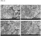
- the anode active materials for a pseudocapacitor according to the example and comparative examples were photographed using a scanning electron microscope (SEM) at different magnifications. The photographed images are shown in FIG. 1 (Example 1), FIG. 2 (Comparative Example 1), FIG. 3 (Comparative Example 2), and FIG. 4 (Comparative Example 3).
- the aggregation phenomenon of the bismuth(III) oxide nanoparticles according to Example 1 was not relatively severe, as compared with those of the bismuth(III) oxides according to Comparative Example 2 and Comparative Example 3, and therefore, it may be more appropriately used as an anode active material for a pseudocapacitor.
- the bismuth(III) oxide according to Comparative Example 1 showed a smooth surface, whereas the bismuth(III) oxide according to Example 1 showed a relatively rough surface, implying that accessibility of an electrolyte to the bismuth(III) oxide according to Example 1 is better.
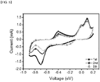
- Pseudocapacitors were manufactured using the anode active materials for a pseudocapacitor according to the example and comparative examples by the following method, and then IVIUMSTAT equipment (manufactured by Ivium Technologies) was used to obtain a cyclic voltammetry graph for each pseudocapacitor.
- Each of the anode active materials, carbon black, and a binder (PVDF) were mixed at a weight ratio of 7:2:1 to prepare a composition for forming an anode.
- the composition was applied onto a glassy carbon electrode (GCE), and then dried under vacuum and dried at 70 °C for 24 hours.
- An electrolyte (1 M Li 2 SO 4 ) was impregnated into the manufactured electrode, and stabilized, followed by cyclic voltammetry using a platinum counter electrode and an SCE reference electrode. At this time, cyclic voltammetry was performed in the potential range of - 0.9 V to 0.2 V at a scan rate of 10 mV/s.
- the pseudocapacitor to which the anode active material of Example 1 was applied showed high specific capacitance of 192.25 F/g and specific capacitance of 155.92 F/g even after a 5 th cycle.
- anode active materials according to the comparative examples were prepared under reflux conditions similar to those of the example, they showed remarkably low specific capacitance, as compared with that of Example 1.
Landscapes
- Engineering & Computer Science (AREA)
- Power Engineering (AREA)
- Microelectronics & Electronic Packaging (AREA)
- Chemical & Material Sciences (AREA)
- Materials Engineering (AREA)
- Manufacturing & Machinery (AREA)
- Chemical Kinetics & Catalysis (AREA)
- Electric Double-Layer Capacitors Or The Like (AREA)
Abstract
Description
- The present application is based on, and claims priority from, Korean Patent Application No.
10-2017-0158926, filed on November 24, 2017 - The present invention relates to a method of preparing an anode active material for a pseudocapacitor.
- Electrochemical capacitors are devices that store electrical energy by forming an electrical double layer between the surface of an electrode and an electrolyte. Capacitors have an almost infinite lifetime without damage to the electrode itself, and can store a large amount of current in a short time owing to their short charge/discharge time. For this reason, capacitors are electrical storage devices which may be usefully applied in fields where high output power is required.
- With an increasing demand for an energy storage device having both high energy density and high output power, there is a growing interest in supercapacitors having higher energy density than known general capacitors and having much better output characteristics than lithium ion batteries.
- Based on the energy storage mechanisms, supercapacitors may be classified into electrical double-layer capacitors (EDLCs) and pseudocapacitors.
- Among them, EDLCs are based on the electrochemical phenomenon of the surface of carbon materials. Although EDLCs exhibit high output characteristics, they are applied only in limited fields because of relatively low energy density.
- Pseudocapacitors store charges through a faradaic reaction that occurs on the nanostructured surface, and exhibit greater capacitance through reversible oxidation/reduction reactions at the electrode/electrolyte interface. Thus, pseudocapacitors are emerging as an alternative that can overcome the low specific capacitance of EDLCs.
- However, in the case of pseudocapacitors operated in aqueous electrolytes, the kind of anode active materials known to be applicable is limited to bismuth oxide (Bi2O3), vanadium oxide (V2O5), etc. In particular, although a variety of methods such as SILAR, a hydrothermal method, an electrodeposition method, a sol-gel method, etc. are known as a method of preparing the anode active material, anode active materials prepared by these methods have limitations in that they cannot exhibit sufficient electrochemical characteristics.
- The present invention provides a method of preparing an anode active material for a pseudocapacitor, which enables expression of high specific capacitance and excellent output characteristics.
- According to the present invention, a method of preparing an anode active material for a pseudocapacitor is provided, the method including the steps of:
- forming a first precipitate by dropwise adding triethanolamine to a bismuth nitrate (Bi(NO3)3) aqueous solution;
- obtaining a second precipitate by refluxing the solution containing the first precipitate; and
- obtaining bismuth(III) oxide nanoparticles by heat-treating the second precipitate.
- Hereinafter, a method of preparing an anode active material for a pseudocapacitor according to embodiments of the present invention will be described in detail.
- The terminology used herein is only for the purpose of describing particular embodiments and is not intended to be limiting of the invention, unless the context clearly indicates otherwise.
- As used herein, the singular forms are intended to include plural forms as well, unless the context clearly indicates otherwise.
- It will be further understood that the terms "include" or "including" when used in this specification, specify the stated features, regions, integers, steps, operations, elements, and/or components, but do not preclude the presence or addition of other features, regions, integers, steps, operations, elements, components, and/or groups.
- Meanwhile, the present inventors have continued to study, and as a result, they found that when triethanolamine is dropwise added to a bismuth nitrate aqueous solution to form a precipitate, which is then subjected to a simplified reaction process of refluxing, bismuth(III) oxide nanoparticles may be synthesized. It was also confirmed that when the bismuth(III) oxide nanoparticles prepared by this method are applied to an anode active material for a pseudocapacitor, high specific capacitance and excellent output characteristics may be expressed.
- Particularly, during formation of the precipitate by dropwise adding triethanolamine and the subsequent refluxing process, bismuth cations (Bi3+) are easily generated through the ionic reaction between bismuth nitrate and triethanolamine, and through the refluxing process, the bismuth cations (Bi3+) bind to hydroxide anions (OH-) to produce final stable bismuth(III) oxide nanoparticles via an unstable Bi(OH)3 phase. The anode material synthesized by such processes has a structural feature of relatively small aggregation, and thus enables expression of high specific capacitance and excellent output characteristics, as compared with nanoparticles having the same composition prepared by any method other than the above processes.
- According to one embodiment of the present invention, a method of preparing an anode active material for a pseudocapacitor is provided, the method including the steps of:
- forming a first precipitate by dropwise adding triethanolamine to a bismuth nitrate (Bi(NO3)3) aqueous solution;
- obtaining a second precipitate by refluxing the solution containing the first precipitate; and
- obtaining bismuth(III) oxide nanoparticles by heat-treating the second precipitate.
- Hereinafter, each of the steps which may be included in the method of preparing the anode active material for a pseudocapacitor will be described in more detail.
- According to an embodiment of the present invention, the step of forming a first precipitate by dropwise adding triethanolamine to a bismuth nitrate (Bi(NO3)3) aqueous solution is performed.
- The bismuth nitrate aqueous solution is a homogeneous mixture in which bismuth nitrate is dissolved in a solvent such as distilled water or deionized water.
- Preferably, the bismuth nitrate aqueous solution may be a 50 to 100 mN (based on bismuth) aqueous solution containing bismuth nitrate(III) pentahydrate (Bi(NO3)3·5H2O) as a solute. Specifically, a concentration of the bismuth nitrate aqueous solution may preferably be 50 mN or more, or 55 mN or more, and 100 mN or less, 90 mN or less, 80 mN or less, or 70 mN or less, based on bismuth.
- That is, to allow sufficient formation of the precipitate by dropwise adding triethanolamine, the concentration of the bismuth nitrate aqueous solution is preferably 50 mN or more. However, when the concentration is too high, the unreacted solute may be included in the precipitate to decrease the efficiency of the precipitate formation reaction. Thus, the concentration of the bismuth nitrate aqueous solution is preferably 100 mN or less.
- The triethanolamine is added dropwise to the bismuth nitrate aqueous solution to allow a first white precipitate to be slowly formed.
- In this regard, the triethanolamine is added dropwise at a volume ratio of 1:0.001 to 1:0.1, based on the volume of the bismuth nitrate aqueous solution. Specifically, the triethanolamine may preferably be added dropwise at a volume ratio of 1:0.001 or more, 1: 0.005 or more, 1:0.010 or more, or 1:0.015 or more, and 1:0.1 or less, 1: 0.05 or less, or 1:0.025 or less, based on the volume of the bismuth nitrate aqueous solution.
- In other words, to allow sufficient formation of the first precipitate by dropwise adding the triethanolamine, the triethanolamine is preferably added dropwise at a volume ratio of 1:0.001 or more with respect to the bismuth nitrate aqueous solution. However, when an excess amount of triethanolamine is added, the efficiency of the first precipitate formation may be decreased. Therefore, the triethanolamine is preferably added dropwise at a volume ratio of 1:0.1 or less with respect to the bismuth nitrate aqueous solution.
- The step of obtaining a second precipitate by refluxing the solution containing the first precipitate is performed.
- The refluxing may be performed using a common reflux apparatus.
- As a non-limiting example, the solution containing the first precipitate is put in an appropriate vessel, for example, a round-bottom flask. This vessel is connected to a water-cooled Liebig or Vigreux condenser, which is generally open to the atmosphere at the top. The vessel is directly or indirectly heated to boil the solution containing the first precipitate. Vapor produced from the solution may be condensed by the condenser, and returned to the vessel by gravity. Through refluxing, formation of the nanoparticle-phased second precipitate from the first precipitate may be facilitated, and a precursor of the anode active material that enables expression of the effects according to the present invention may be formed.
- According to an embodiment of the present invention, the refluxing is preferably performed at 50 °C to 100 °C for 5 hours to 24 hours.
- That is, the refluxing may be continuously performed at a 100 °C or lower which is a boiling point of the solvent for 5 hours to 24 hours, 10 hours to 24 hours, or 12 hours to 24 hours, which is advantageous in terms of formation of the nanoparticle-phased second precipitate. However, when the refluxing is performed at an excessively low temperature and/or for a very short time, the efficiency of the second precipitate formation may be reduced. Therefore, the refluxing may preferably be performed at a temperature of 50 °C or higher, 60 °C or higher, or 70 °C or higher for the above range of time.
- Through the refluxing, the white nanoparticle-phased second precipitate is formed in the vessel. The second precipitate has the same composition as the first precipitate. However, the first precipitate in a form in which it is difficult to specify its particle size is contained in the solution, and through the refluxing, the second precipitate having a nanoscale particle size may be obtained.
- The second precipitate precipitated in the vessel may be separated by a common method, such as centrifugation, etc.
- Optionally, a step of washing the second precipitate may be further performed.
- The washing is a process of removing impurities from the second precipitate. The washing may be performed by a method of washing the second precipitate several times using a solvent such as distilled water, deionized water, or ethanol.
- Optionally, a step of drying the washed second precipitate may be further performed. The drying may be performed using a vacuum oven. Alternatively, the drying may be performed by a common freeze-drying method.
- Preferably, the drying may be performed at a temperature of 20 °C to 80 °C. Specifically, the drying may be performed at a temperature of 20 °C or higher, 25 °C or higher, 40 °C or higher, or 60 °C or higher, and 80 °C or lower, or 70 °C or lower.
- Subsequently, the step of obtaining bismuth(III) oxide nanoparticles by heat-treating the second precipitate is performed.
- According to an embodiment of the present invention, the heat-treatment may be performed in an oxygen atmosphere at 150 °C to 300 °C for 1 hour to 5 hours, which is preferable in terms of obtaining the bismuth(III) oxide nanoparticles as an anode active material satisfying the above-described characteristics.
- Specifically, the heat treatment may be performed in an oxygen atmosphere at 150 °C or higher, or 200 °C or higher; and 300 °C or lower, or 250 °C or lower, and the heat treatment may be continuously or discontinuously performed for 60 minutes or longer, 90 minutes or longer, or 120 minutes or longer, and 300 minutes or shorter, 240 minutes or shorter, or 180 minutes or shorter.
- Optionally, the step of pulverizing the bismuth(III) oxide nanoparticles obtained by the above heat-treatment may be performed.
- The pulverizing is a step of providing an anode active material having more improved activity by increasing a specific surface area of the bismuth(III) oxide nanoparticles. This step may be optionally performed.
- According to an embodiment of the present invention, the bismuth(III) oxide nanoparticles prepared by the above-described method may have an average particle diameter of 500 nm to 5000 nm.
- Here, the average particle diameter of the nanoparticles means an arithmetic mean calculated based on the greatest outer diameter of individual particles, as measured with a scanning electron microscope.
- The bismuth(III) oxide nanoparticles prepared by the above method may be applied to an anode active material for a pseudocapacitor, which enables expression of high specific capacitance and excellent output characteristics.
- Meanwhile, the anode for a pseudocapacitor may include common components such as a conductive material and a binder, together with the bismuth(III) oxide nanoparticles prepared by the above method.
- The conductive material is used to provide an anode with conductivity, and is not particularly limited as long as it has electrical conductivity without causing chemical changes. Non-limiting examples of the conductive material may include natural graphite, artificial graphite, carbon black, acetylene black, Ketjen black, channel black, furnace black, lamp black, thermal black, carbon fibers, etc.
- Further, the binder may be used to improve adhesion between materials constituting the anode, and adhesive force between the collector and the anode. Non-limiting examples of the binder may include polyvinylidene fluoride (PVDF), a vinylidene fluoride-hexafluoropropylene copolymer (PVDF-co-HFP), polyvinyl alcohol, polyacrylonitrile, carboxymethyl cellulose, starch, hydroxypropyl cellulose, polyvinyl pyrrolidone, tetrafluoroethylene, polyethylene, polypropylene, an ethylene-propylene-diene polymer (EPDM), sulfonated-EPDM, styrene butadiene rubber (SBR), fluorine rubber, etc.
- The anode for a pseudocapacitor may be manufactured by applying the above-described components onto a collector made of a material such as copper, aluminum, nickel, or stainless steel, followed by pressing and drying.
- The pseudocapacitor may have a structure including the anode, a common positive electrode, a separator interposed between the positive electrode and the anode, and an electrolyte.
- According to the present invention, a method of preparing an anode active material for a pseudocapacitor, which enables expression of high specific capacitance and excellent output characteristics, is provided.
-
-
FIG. 1 shows scanning electron microscopic (SEM) images of an anode active material prepared according to Example 1, photographed at different magnifications; -
FIG. 2 shows SEM images of an anode active material prepared according to Comparative Example 1, photographed at different magnifications; -
FIG. 3 shows SEM images of an anode active material prepared according to Comparative Example 2, photographed at different magnifications; -
FIG. 4 shows SEM images of an anode active material prepared according to Comparative Example 3, photographed at different magnifications; -
FIG. 5 shows a cyclic voltammetry graph for a pseudocapacitor to which the anode active material according to Example 1 was applied; -
FIG. 6 shows a cyclic voltammetry graph for a pseudocapacitor to which the anode active material according to Comparative Example 1 was applied; -
FIG. 7 shows a cyclic voltammetry graph for a pseudocapacitor to which the anode active material according to Comparative Example 2 was applied; and -
FIG. 8 shows a cyclic voltammetry graph for a pseudocapacitor to which the anode active material according to Comparative Example 3 was applied. - Hereinafter, preferred examples will be provided for better understanding of the present invention. However, the following examples are for illustrative purposes only, and the present invention is not intended to be limited thereby.
- 3.0 g of bismuth nitrate(III) pentahydrate (Bi(NO3)3·5H2O) and 100 mL of deionized water were put into and stirred in a round bottom flask having a volume of 250 mL to prepare a homogeneous bismuth nitrate aqueous solution.
- A total of 2 mL of triethanolamine was slowly added dropwise to the round bottom flask, and formation of a first white precipitate was confirmed.
- The round bottom flask was placed in a reflux apparatus provided with a condenser, a heating mantle, and a thermocouple probe, followed by refluxing for 12 hours while heating at a temperature of 70 °C. By refluxing, a second white precipitate having a nanoscale particle size was formed from the first precipitate.
- The second precipitate was recovered using a centrifuge, and then washed with deionized water and ethanol to remove impurities.
- The washed second precipitate was dried in a vacuum oven at 70 °C.
- The dried second precipitate was continuously heat-treated in an oxygen atmosphere at 200 °C for 2 hours to obtain bismuth(III) oxide nanoparticles (SDH-68).
- 3.0 g of bismuth nitrate(III) pentahydrate (Bi(NO3)3·5H2O) and 6 mL of 60 % nitric acid were put into and stirred in a round bottom flask having a volume of 250 mL to prepare a homogeneous solution.
- 30 mL of propanol and 30 mL of N-methyl-2-pyrrolidone were added to the round bottom flask, followed by stirring.
- 1 g of citric acid was added thereto, and further stirred, and then 20 ml of a 9 M NaOH aqueous solution was added dropwise thereto to confirm formation of a precipitate.
- The round bottom flask was placed in a reflux apparatus provided with a condenser, a heating mantle, and a thermocouple probe, followed by refluxing for 12 hours while heating at a temperature of 80 °C. By refluxing, a nanoscale precipitate was formed.
- The nanoscale precipitate was recovered using a centrifuge, and then washed with deionized water and ethanol to remove impurities.
- The washed precipitate was dried in a vacuum oven at 70 °C.
- The dried precipitate was continuously heat-treated in an oxygen atmosphere at 400 °C for 2 hours to obtain bismuth(III) oxide (SDH-63).
- 3.0 g of bismuth nitrate(III) pentahydrate (Bi(NO3)3·5H2O) and 6 mL of 60 % nitric acid were put into and stirred in a round bottom flask having a volume of 250 mL to prepare a homogeneous solution.
- 60 mL of propanol and 60 mL of N-methyl-2-pyrrolidone were added to the round bottom flask, followed by stirring.
- 1 g of citric acid and 1 g of carbon nanotube powder were added thereto, and further stirred, and then 20 ml of a 9 M NaOH aqueous solution was added dropwise thereto to confirm formation of a precipitate.
- The round bottom flask was placed in a reflux apparatus provided with a condenser, a heating mantle, and a thermocouple probe, followed by refluxing for 12 hours while heating at a temperature of 80 °C. By refluxing, a nanoscale precipitate was formed.
- The nanoscale precipitate was recovered using a centrifuge, and then washed with deionized water and ethanol to remove impurities.
- The washed precipitate was dried in a vacuum oven at 70 °C.
- The dried precipitate was continuously heat-treated in an oxygen atmosphere at 200 °C for 2 hours to obtain a bismuth(III) oxide nanoparticle-containing carbon nanotube complex (SDH-66).
- 3.0 g of bismuth nitrate(III) pentahydrate (Bi(NO3)3·5H2O) and 6 mL of 60 % nitric acid were put into and stirred in a round bottom flask having a volume of 250 mL to prepare a homogeneous solution.
- 60 mL of propanol and 60 mL of N-methyl-2-pyrrolidone were added to the round bottom flask, followed by stirring.
- 1 g of citric acid and 1 g of lithium acetate (C2H3LiO2) were added thereto, and further stirred, and then 20 ml of a 9 M NaOH aqueous solution was added dropwise thereto to confirm formation of a precipitate.
- The round bottom flask was placed in a reflux apparatus provided with a condenser, a heating mantle, and a thermocouple probe, followed by refluxing for 12 hours while heating at a temperature of 80 °C. By refluxing, a nanoscale precipitate was formed.
- The nanoscale precipitate was recovered using a centrifuge, and then washed with deionized water and ethanol to remove impurities.
- The washed precipitate was dried in a vacuum oven at 70 °C.
- The dried precipitate was continuously heat-treated in an oxygen atmosphere at 200 °C for 2 hours to obtain excess lithium-containing bismuth(III) oxide (SDH-70).
- The anode active materials for a pseudocapacitor according to the example and comparative examples were photographed using a scanning electron microscope (SEM) at different magnifications. The photographed images are shown in
FIG. 1 (Example 1),FIG. 2 (Comparative Example 1),FIG. 3 (Comparative Example 2), andFIG. 4 (Comparative Example 3). - Referring to
FIGS. 1 to 4 , it was confirmed that the aggregation phenomenon of the bismuth(III) oxide nanoparticles according to Example 1 was not relatively severe, as compared with those of the bismuth(III) oxides according to Comparative Example 2 and Comparative Example 3, and therefore, it may be more appropriately used as an anode active material for a pseudocapacitor. The bismuth(III) oxide according to Comparative Example 1 showed a smooth surface, whereas the bismuth(III) oxide according to Example 1 showed a relatively rough surface, implying that accessibility of an electrolyte to the bismuth(III) oxide according to Example 1 is better. - Pseudocapacitors were manufactured using the anode active materials for a pseudocapacitor according to the example and comparative examples by the following method, and then IVIUMSTAT equipment (manufactured by Ivium Technologies) was used to obtain a cyclic voltammetry graph for each pseudocapacitor.
- Each of the anode active materials, carbon black, and a binder (PVDF) were mixed at a weight ratio of 7:2:1 to prepare a composition for forming an anode. The composition was applied onto a glassy carbon electrode (GCE), and then dried under vacuum and dried at 70 °C for 24 hours. An electrolyte (1 M Li2SO4) was impregnated into the manufactured electrode, and stabilized, followed by cyclic voltammetry using a platinum counter electrode and an SCE reference electrode. At this time, cyclic voltammetry was performed in the potential range of - 0.9 V to 0.2 V at a scan rate of 10 mV/s.
- The cyclic voltammetry graphs thus obtained by the method are shown in
FIG. 5 (Example 1),FIG. 6 (Comparative Example 1),FIG. 7 (Comparative Example 2), andFIG. 8 (Comparative Example 3), and the measured values of specific capacitance are shown in the following Table 1.[Table 1] Cycle Example 1 Comparative Example 1 Comparative Example 2 Comparative Example 3 1st 192.25 F/g 106.62 F/g 73.57 F/g 31.03 F/ g 2nd 177.33 F/g 101.13 F/g 66.89 F/g 27.36 F/ g 5th 155.92 F/g 96.52 F/g 60.89 F/g 27.02 F/g - Referring to Table 1 and
FIGS. 5 to 8 , the pseudocapacitor to which the anode active material of Example 1 was applied showed high specific capacitance of 192.25 F/g and specific capacitance of 155.92 F/g even after a 5th cycle. - Although the anode active materials according to the comparative examples were prepared under reflux conditions similar to those of the example, they showed remarkably low specific capacitance, as compared with that of Example 1.
Claims (7)
- A method of preparing an anode active material for a pseudocapacitor, the method comprising the steps of:forming a first precipitate by dropwise adding triethanolamine to a bismuth nitrate (Bi(NO3)3) aqueous solution;obtaining a second precipitate by refluxing the solution containing the first precipitate; andobtaining bismuth(III) oxide nanoparticles by heat-treating the second precipitate.
- The method of claim 1, wherein the bismuth nitrate aqueous solution is a 50 to 100 mN (based on bismuth) aqueous solution containing bismuth nitrate(III) pentahydrate (Bi(NO3)3·5H2O) as a solute.
- The method of claim 1, wherein the triethanolamine is added dropwise at a volume ratio of 1:0.001 to 1:0.1, based on the volume of the bismuth nitrate aqueous solution.
- The method of claim 1, wherein the refluxing is performed at 50 °C to 100 °C for 5 hours to 24 hours.
- The method of claim 1, wherein the heat treatment is performed in an oxygen atmosphere at 150 °C to 300 °C for 1 hour to 5 hours.
- The method of claim 1, comprising the steps of:forming a first precipitate by dropwise adding triethanolamine to a bismuth nitrate (Bi(NO3)3) aqueous solution;obtaining a second precipitate by refluxing the solution containing the first precipitate;washing the second precipitate;drying the washed second precipitate; andobtaining bismuth(III) oxide nanoparticles by heat-treating the dried second precipitate.
- The method of claim 1, wherein the bismuth(III) oxide nanoparticles have an average particle diameter of 500 nm to 5000 nm, based on the greatest outer diameter of individual particles, as measured by a scanning electron microscope.
Applications Claiming Priority (2)
| Application Number | Priority Date | Filing Date | Title |
|---|---|---|---|
| KR1020170158926A KR102364364B1 (en) | 2017-11-24 | 2017-11-24 | Process for preparing anode active material for pseudocapacitor |
| PCT/KR2018/012276 WO2019103314A1 (en) | 2017-11-24 | 2018-10-17 | Manufacturing method of cathode active material for water pipe capacitor |
Publications (3)
| Publication Number | Publication Date |
|---|---|
| EP3621094A1 true EP3621094A1 (en) | 2020-03-11 |
| EP3621094A4 EP3621094A4 (en) | 2020-07-08 |
| EP3621094B1 EP3621094B1 (en) | 2022-10-05 |
Family
ID=66632112
Family Applications (1)
| Application Number | Title | Priority Date | Filing Date |
|---|---|---|---|
| EP18880956.0A Active EP3621094B1 (en) | 2017-11-24 | 2018-10-17 | Process for preparing anode active material for pseudocapacitor |
Country Status (6)
| Country | Link |
|---|---|
| US (1) | US11276533B2 (en) |
| EP (1) | EP3621094B1 (en) |
| JP (1) | JP6953061B2 (en) |
| KR (1) | KR102364364B1 (en) |
| CN (1) | CN110770863B (en) |
| WO (1) | WO2019103314A1 (en) |
Family Cites Families (20)
| Publication number | Priority date | Publication date | Assignee | Title |
|---|---|---|---|---|
| US5070050A (en) * | 1988-10-14 | 1991-12-03 | Raychem Corporation | Metal oxide dielectric dense bodies, precursor powders therefor, and methods for preparing same |
| JP2701065B2 (en) * | 1989-03-23 | 1998-01-21 | 日東化学工業株式会社 | Preparation of molybdenum-bismuth-containing composite oxide catalyst |
| US7972726B2 (en) * | 2006-07-10 | 2011-07-05 | The Gillette Company | Primary alkaline battery containing bismuth metal oxide |
| CN100584763C (en) | 2006-11-10 | 2010-01-27 | 宝山钢铁股份有限公司 | The preparation method of bismuth trioxide |
| KR100927181B1 (en) | 2008-01-15 | 2009-11-18 | 재단법인서울대학교산학협력재단 | Synthetic method of multiferroic bismuth ferrite powder |
| KR20120098588A (en) * | 2009-07-02 | 2012-09-05 | 다우 코닝 코포레이션 | Methods for preparing polyheterosiloxanes |
| JP5637671B2 (en) | 2009-09-16 | 2014-12-10 | 上村工業株式会社 | Electro copper plating bath and electroplating method using the electro copper plating bath |
| WO2013191075A1 (en) | 2012-06-21 | 2013-12-27 | 東亞合成株式会社 | Amorphous inorganic anion exchanger, resin composition for sealing electronic component, and method for producing amorphous bismuth compound |
| WO2015040212A1 (en) | 2013-09-20 | 2015-03-26 | Tillotts Pharma Ag | Delayed release pharmaceutical formulation |
| CN104752069B (en) * | 2013-12-31 | 2018-10-26 | 西北大学 | A kind of preparation method of metal oxide or metal oxide composite |
| CN104174415B (en) | 2014-07-21 | 2016-05-04 | 浙江大学 | A kind of Bi2O3/ BiOX nano-heterogeneous structure hollow ball and preparation method thereof |
| CN104140097B (en) | 2014-07-25 | 2016-06-08 | 深圳新宙邦科技股份有限公司 | A kind of phosphorus doping Graphene and preparation method thereof |
| CN104795536B (en) | 2015-04-19 | 2017-08-29 | 宁波大学 | A kind of liquid phase synthesis B3+, La3+Orthohormbic structure of adulterating fluorination bismuth anode material for lithium-ion batteries and preparation method thereof |
| CN107531661B (en) * | 2015-04-23 | 2024-05-28 | Sfc株式会社 | Compound for organic light-emitting element and organic light-emitting element including the compound |
| CN105024056B (en) | 2015-06-05 | 2017-04-05 | 中南大学 | A kind of sodium-ion battery bismuth/nitrating carbon ball anode material and preparation method thereof |
| JP6647031B2 (en) | 2015-12-09 | 2020-02-14 | ナミックス株式会社 | Resin composition, conductive copper paste, cured product, semiconductor device |
| CN106410128A (en) | 2016-07-18 | 2017-02-15 | 苏州大学 | Preparation method of graphene-bismuth oxide composite material for lithium ion battery cathode |
| CN106298263B (en) | 2016-10-31 | 2018-05-15 | 湘潭大学 | A kind of bismuth/charcoal super capacitance cell and preparation method thereof |
| CN106449151B (en) | 2016-11-30 | 2018-07-20 | 湘潭大学 | A kind of bismuthic acid lithium/charcoal super capacitance cell and preparation method thereof |
| CN106964334B (en) | 2017-05-05 | 2019-08-20 | 国家纳米科学中心 | A kind of full-spectrum responsive catalyst material and its preparation method and application |
-
2017
- 2017-11-24 KR KR1020170158926A patent/KR102364364B1/en active Active
-
2018
- 2018-10-17 WO PCT/KR2018/012276 patent/WO2019103314A1/en not_active Ceased
- 2018-10-17 CN CN201880040742.3A patent/CN110770863B/en active Active
- 2018-10-17 EP EP18880956.0A patent/EP3621094B1/en active Active
- 2018-10-17 JP JP2019566698A patent/JP6953061B2/en active Active
- 2018-10-17 US US16/626,188 patent/US11276533B2/en active Active
Also Published As
| Publication number | Publication date |
|---|---|
| JP2020522142A (en) | 2020-07-27 |
| CN110770863B (en) | 2022-09-30 |
| WO2019103314A8 (en) | 2019-11-21 |
| US11276533B2 (en) | 2022-03-15 |
| US20200219668A1 (en) | 2020-07-09 |
| EP3621094B1 (en) | 2022-10-05 |
| WO2019103314A1 (en) | 2019-05-31 |
| KR20190060582A (en) | 2019-06-03 |
| EP3621094A4 (en) | 2020-07-08 |
| CN110770863A (en) | 2020-02-07 |
| JP6953061B2 (en) | 2021-10-27 |
| KR102364364B1 (en) | 2022-02-16 |
Similar Documents
| Publication | Publication Date | Title |
|---|---|---|
| JP7042589B2 (en) | Negative electrode | |
| Matheswaran et al. | A binder-free Ni 2 P 2 O 7/Co 2 P 2 O 7 nanograss array as an efficient cathode for supercapacitors | |
| Auxilia et al. | Au@ TiO2/reduced graphene oxide nanocomposites for lithium-ion capacitors | |
| US11530136B2 (en) | Preparation method of hexagonal molybdenum oxide nanorod | |
| JP2023508021A (en) | Positive electrode active material, manufacturing method thereof, and lithium secondary battery including the same | |
| WO2022085694A1 (en) | Nonaqueous alkali metal power storage element and positive electrode coating liquid | |
| CN110289180A (en) | Two-dimensional transition metal carbide/titanium dioxide/graphene composite material, its preparation and application | |
| CN107346711A (en) | A kind of composite PANI/Ti3C2TxPreparation and application | |
| KR20140137792A (en) | Oxide capped anode materials for high performance lithium ion batteries | |
| KR20170120735A (en) | Method for menufacturing a cathode of lithium primary battery | |
| KR20200068839A (en) | A method of manufacturing an electrode for a super capacitor including crumpled graphene and an electrode for a supercapacitor prepared thereby | |
| CN113629249A (en) | Preparation method of MXene-based supported platinum catalyst applied to lithium-sulfur battery anode | |
| JP2018056410A (en) | Non-aqueous lithium storage element | |
| CN109767925B (en) | T-Nb for lithium ion super capacitor2O5Egg white carbon composite material and preparation method thereof | |
| CN111063549B (en) | Two-dimensional MOFs nanosheet-derived hybrid capacitor all-electrode materials | |
| JP2010040480A (en) | Material of electrode, electrode, lithium-ion battery, electric double-layered capacitor, manufacturing method for material of electrode | |
| Wang et al. | Self-assembled VN/Ti 3 C 2 T x composites for asymmetric supercapacitors | |
| Huang et al. | Facile synthesis and application of V2O5/MXene nanocomposites as electrode materials for supercapacitors | |
| WO2019059719A2 (en) | Negative electrode material for pseudocapacitor and method for manufacturing same | |
| EP3621094B1 (en) | Process for preparing anode active material for pseudocapacitor | |
| KR101973050B1 (en) | Super capacitor electrode material with titanate of porous structure and carbon materials and method of preparation of the same | |
| HK1258363A1 (en) | Nanoparticle/porous graphene composite, synthesizing methods and applications of same | |
| JP2018056436A (en) | Non-aqueous lithium storage element | |
| JP2020140889A (en) | Positive electrode for non-aqueous lithium-type power storage element | |
| Tian et al. | Preparation and capacitive properties of lithium manganese oxide intercalation compound |
Legal Events
| Date | Code | Title | Description |
|---|---|---|---|
| STAA | Information on the status of an ep patent application or granted ep patent |
Free format text: STATUS: THE INTERNATIONAL PUBLICATION HAS BEEN MADE |
|
| PUAI | Public reference made under article 153(3) epc to a published international application that has entered the european phase |
Free format text: ORIGINAL CODE: 0009012 |
|
| STAA | Information on the status of an ep patent application or granted ep patent |
Free format text: STATUS: REQUEST FOR EXAMINATION WAS MADE |
|
| 17P | Request for examination filed |
Effective date: 20191205 |
|
| AK | Designated contracting states |
Kind code of ref document: A1 Designated state(s): AL AT BE BG CH CY CZ DE DK EE ES FI FR GB GR HR HU IE IS IT LI LT LU LV MC MK MT NL NO PL PT RO RS SE SI SK SM TR |
|
| AX | Request for extension of the european patent |
Extension state: BA ME |
|
| A4 | Supplementary search report drawn up and despatched |
Effective date: 20200608 |
|
| RIC1 | Information provided on ipc code assigned before grant |
Ipc: H01G 11/46 20130101ALI20200602BHEP Ipc: H01G 11/86 20130101ALI20200602BHEP Ipc: H01G 11/34 20130101AFI20200602BHEP Ipc: H01G 11/24 20130101ALI20200602BHEP Ipc: H01G 11/02 20130101ALI20200602BHEP |
|
| DAV | Request for validation of the european patent (deleted) | ||
| DAX | Request for extension of the european patent (deleted) | ||
| RAP1 | Party data changed (applicant data changed or rights of an application transferred) |
Owner name: LG ENERGY SOLUTION LTD. |
|
| RAP3 | Party data changed (applicant data changed or rights of an application transferred) |
Owner name: LG ENERGY SOLUTION, LTD. |
|
| GRAP | Despatch of communication of intention to grant a patent |
Free format text: ORIGINAL CODE: EPIDOSNIGR1 |
|
| STAA | Information on the status of an ep patent application or granted ep patent |
Free format text: STATUS: GRANT OF PATENT IS INTENDED |
|
| INTG | Intention to grant announced |
Effective date: 20220715 |
|
| GRAS | Grant fee paid |
Free format text: ORIGINAL CODE: EPIDOSNIGR3 |
|
| GRAA | (expected) grant |
Free format text: ORIGINAL CODE: 0009210 |
|
| STAA | Information on the status of an ep patent application or granted ep patent |
Free format text: STATUS: THE PATENT HAS BEEN GRANTED |
|
| AK | Designated contracting states |
Kind code of ref document: B1 Designated state(s): AL AT BE BG CH CY CZ DE DK EE ES FI FR GB GR HR HU IE IS IT LI LT LU LV MC MK MT NL NO PL PT RO RS SE SI SK SM TR |
|
| REG | Reference to a national code |
Ref country code: GB Ref legal event code: FG4D |
|
| REG | Reference to a national code |
Ref country code: CH Ref legal event code: EP |
|
| REG | Reference to a national code |
Ref country code: AT Ref legal event code: REF Ref document number: 1523266 Country of ref document: AT Kind code of ref document: T Effective date: 20221015 |
|
| REG | Reference to a national code |
Ref country code: DE Ref legal event code: R096 Ref document number: 602018041550 Country of ref document: DE |
|
| REG | Reference to a national code |
Ref country code: IE Ref legal event code: FG4D |
|
| REG | Reference to a national code |
Ref country code: LT Ref legal event code: MG9D |
|
| REG | Reference to a national code |
Ref country code: NL Ref legal event code: MP Effective date: 20221005 |
|
| REG | Reference to a national code |
Ref country code: AT Ref legal event code: MK05 Ref document number: 1523266 Country of ref document: AT Kind code of ref document: T Effective date: 20221005 |
|
| PG25 | Lapsed in a contracting state [announced via postgrant information from national office to epo] |
Ref country code: NL Free format text: LAPSE BECAUSE OF FAILURE TO SUBMIT A TRANSLATION OF THE DESCRIPTION OR TO PAY THE FEE WITHIN THE PRESCRIBED TIME-LIMIT Effective date: 20221005 |
|
| PG25 | Lapsed in a contracting state [announced via postgrant information from national office to epo] |
Ref country code: SE Free format text: LAPSE BECAUSE OF FAILURE TO SUBMIT A TRANSLATION OF THE DESCRIPTION OR TO PAY THE FEE WITHIN THE PRESCRIBED TIME-LIMIT Effective date: 20221005 Ref country code: PT Free format text: LAPSE BECAUSE OF FAILURE TO SUBMIT A TRANSLATION OF THE DESCRIPTION OR TO PAY THE FEE WITHIN THE PRESCRIBED TIME-LIMIT Effective date: 20230206 Ref country code: NO Free format text: LAPSE BECAUSE OF FAILURE TO SUBMIT A TRANSLATION OF THE DESCRIPTION OR TO PAY THE FEE WITHIN THE PRESCRIBED TIME-LIMIT Effective date: 20230105 Ref country code: LT Free format text: LAPSE BECAUSE OF FAILURE TO SUBMIT A TRANSLATION OF THE DESCRIPTION OR TO PAY THE FEE WITHIN THE PRESCRIBED TIME-LIMIT Effective date: 20221005 Ref country code: FI Free format text: LAPSE BECAUSE OF FAILURE TO SUBMIT A TRANSLATION OF THE DESCRIPTION OR TO PAY THE FEE WITHIN THE PRESCRIBED TIME-LIMIT Effective date: 20221005 Ref country code: ES Free format text: LAPSE BECAUSE OF FAILURE TO SUBMIT A TRANSLATION OF THE DESCRIPTION OR TO PAY THE FEE WITHIN THE PRESCRIBED TIME-LIMIT Effective date: 20221005 Ref country code: AT Free format text: LAPSE BECAUSE OF FAILURE TO SUBMIT A TRANSLATION OF THE DESCRIPTION OR TO PAY THE FEE WITHIN THE PRESCRIBED TIME-LIMIT Effective date: 20221005 |
|
| PG25 | Lapsed in a contracting state [announced via postgrant information from national office to epo] |
Ref country code: RS Free format text: LAPSE BECAUSE OF FAILURE TO SUBMIT A TRANSLATION OF THE DESCRIPTION OR TO PAY THE FEE WITHIN THE PRESCRIBED TIME-LIMIT Effective date: 20221005 Ref country code: PL Free format text: LAPSE BECAUSE OF FAILURE TO SUBMIT A TRANSLATION OF THE DESCRIPTION OR TO PAY THE FEE WITHIN THE PRESCRIBED TIME-LIMIT Effective date: 20221005 Ref country code: LV Free format text: LAPSE BECAUSE OF FAILURE TO SUBMIT A TRANSLATION OF THE DESCRIPTION OR TO PAY THE FEE WITHIN THE PRESCRIBED TIME-LIMIT Effective date: 20221005 Ref country code: IS Free format text: LAPSE BECAUSE OF FAILURE TO SUBMIT A TRANSLATION OF THE DESCRIPTION OR TO PAY THE FEE WITHIN THE PRESCRIBED TIME-LIMIT Effective date: 20230205 Ref country code: HR Free format text: LAPSE BECAUSE OF FAILURE TO SUBMIT A TRANSLATION OF THE DESCRIPTION OR TO PAY THE FEE WITHIN THE PRESCRIBED TIME-LIMIT Effective date: 20221005 Ref country code: GR Free format text: LAPSE BECAUSE OF FAILURE TO SUBMIT A TRANSLATION OF THE DESCRIPTION OR TO PAY THE FEE WITHIN THE PRESCRIBED TIME-LIMIT Effective date: 20230106 |
|
| REG | Reference to a national code |
Ref country code: CH Ref legal event code: PL |
|
| P01 | Opt-out of the competence of the unified patent court (upc) registered |
Effective date: 20230408 |
|
| REG | Reference to a national code |
Ref country code: BE Ref legal event code: MM Effective date: 20221031 |
|
| PG25 | Lapsed in a contracting state [announced via postgrant information from national office to epo] |
Ref country code: LU Free format text: LAPSE BECAUSE OF NON-PAYMENT OF DUE FEES Effective date: 20221017 |
|
| REG | Reference to a national code |
Ref country code: DE Ref legal event code: R097 Ref document number: 602018041550 Country of ref document: DE |
|
| PG25 | Lapsed in a contracting state [announced via postgrant information from national office to epo] |
Ref country code: SM Free format text: LAPSE BECAUSE OF FAILURE TO SUBMIT A TRANSLATION OF THE DESCRIPTION OR TO PAY THE FEE WITHIN THE PRESCRIBED TIME-LIMIT Effective date: 20221005 Ref country code: RO Free format text: LAPSE BECAUSE OF FAILURE TO SUBMIT A TRANSLATION OF THE DESCRIPTION OR TO PAY THE FEE WITHIN THE PRESCRIBED TIME-LIMIT Effective date: 20221005 Ref country code: MC Free format text: LAPSE BECAUSE OF FAILURE TO SUBMIT A TRANSLATION OF THE DESCRIPTION OR TO PAY THE FEE WITHIN THE PRESCRIBED TIME-LIMIT Effective date: 20221005 Ref country code: LI Free format text: LAPSE BECAUSE OF NON-PAYMENT OF DUE FEES Effective date: 20221031 Ref country code: EE Free format text: LAPSE BECAUSE OF FAILURE TO SUBMIT A TRANSLATION OF THE DESCRIPTION OR TO PAY THE FEE WITHIN THE PRESCRIBED TIME-LIMIT Effective date: 20221005 Ref country code: DK Free format text: LAPSE BECAUSE OF FAILURE TO SUBMIT A TRANSLATION OF THE DESCRIPTION OR TO PAY THE FEE WITHIN THE PRESCRIBED TIME-LIMIT Effective date: 20221005 Ref country code: CZ Free format text: LAPSE BECAUSE OF FAILURE TO SUBMIT A TRANSLATION OF THE DESCRIPTION OR TO PAY THE FEE WITHIN THE PRESCRIBED TIME-LIMIT Effective date: 20221005 Ref country code: CH Free format text: LAPSE BECAUSE OF NON-PAYMENT OF DUE FEES Effective date: 20221031 |
|
| PLBE | No opposition filed within time limit |
Free format text: ORIGINAL CODE: 0009261 |
|
| STAA | Information on the status of an ep patent application or granted ep patent |
Free format text: STATUS: NO OPPOSITION FILED WITHIN TIME LIMIT |
|
| PG25 | Lapsed in a contracting state [announced via postgrant information from national office to epo] |
Ref country code: SK Free format text: LAPSE BECAUSE OF FAILURE TO SUBMIT A TRANSLATION OF THE DESCRIPTION OR TO PAY THE FEE WITHIN THE PRESCRIBED TIME-LIMIT Effective date: 20221005 Ref country code: AL Free format text: LAPSE BECAUSE OF FAILURE TO SUBMIT A TRANSLATION OF THE DESCRIPTION OR TO PAY THE FEE WITHIN THE PRESCRIBED TIME-LIMIT Effective date: 20221005 |
|
| 26N | No opposition filed |
Effective date: 20230706 |
|
| PG25 | Lapsed in a contracting state [announced via postgrant information from national office to epo] |
Ref country code: BE Free format text: LAPSE BECAUSE OF NON-PAYMENT OF DUE FEES Effective date: 20221031 |
|
| PG25 | Lapsed in a contracting state [announced via postgrant information from national office to epo] |
Ref country code: IE Free format text: LAPSE BECAUSE OF NON-PAYMENT OF DUE FEES Effective date: 20221017 |
|
| PG25 | Lapsed in a contracting state [announced via postgrant information from national office to epo] |
Ref country code: SI Free format text: LAPSE BECAUSE OF FAILURE TO SUBMIT A TRANSLATION OF THE DESCRIPTION OR TO PAY THE FEE WITHIN THE PRESCRIBED TIME-LIMIT Effective date: 20221005 |
|
| PG25 | Lapsed in a contracting state [announced via postgrant information from national office to epo] |
Ref country code: HU Free format text: LAPSE BECAUSE OF FAILURE TO SUBMIT A TRANSLATION OF THE DESCRIPTION OR TO PAY THE FEE WITHIN THE PRESCRIBED TIME-LIMIT; INVALID AB INITIO Effective date: 20181017 |
|
| PG25 | Lapsed in a contracting state [announced via postgrant information from national office to epo] |
Ref country code: CY Free format text: LAPSE BECAUSE OF FAILURE TO SUBMIT A TRANSLATION OF THE DESCRIPTION OR TO PAY THE FEE WITHIN THE PRESCRIBED TIME-LIMIT Effective date: 20221005 |
|
| PG25 | Lapsed in a contracting state [announced via postgrant information from national office to epo] |
Ref country code: MK Free format text: LAPSE BECAUSE OF FAILURE TO SUBMIT A TRANSLATION OF THE DESCRIPTION OR TO PAY THE FEE WITHIN THE PRESCRIBED TIME-LIMIT Effective date: 20221005 Ref country code: IT Free format text: LAPSE BECAUSE OF FAILURE TO SUBMIT A TRANSLATION OF THE DESCRIPTION OR TO PAY THE FEE WITHIN THE PRESCRIBED TIME-LIMIT Effective date: 20221005 |
|
| PG25 | Lapsed in a contracting state [announced via postgrant information from national office to epo] |
Ref country code: TR Free format text: LAPSE BECAUSE OF FAILURE TO SUBMIT A TRANSLATION OF THE DESCRIPTION OR TO PAY THE FEE WITHIN THE PRESCRIBED TIME-LIMIT Effective date: 20221005 |
|
| PG25 | Lapsed in a contracting state [announced via postgrant information from national office to epo] |
Ref country code: BG Free format text: LAPSE BECAUSE OF FAILURE TO SUBMIT A TRANSLATION OF THE DESCRIPTION OR TO PAY THE FEE WITHIN THE PRESCRIBED TIME-LIMIT Effective date: 20221005 |
|
| PG25 | Lapsed in a contracting state [announced via postgrant information from national office to epo] |
Ref country code: MT Free format text: LAPSE BECAUSE OF FAILURE TO SUBMIT A TRANSLATION OF THE DESCRIPTION OR TO PAY THE FEE WITHIN THE PRESCRIBED TIME-LIMIT Effective date: 20221005 |
|
| PGFP | Annual fee paid to national office [announced via postgrant information from national office to epo] |
Ref country code: GB Payment date: 20250922 Year of fee payment: 8 |
|
| PGFP | Annual fee paid to national office [announced via postgrant information from national office to epo] |
Ref country code: FR Payment date: 20250925 Year of fee payment: 8 |
|
| PGFP | Annual fee paid to national office [announced via postgrant information from national office to epo] |
Ref country code: DE Payment date: 20250922 Year of fee payment: 8 |