EP3620952B1 - Optical fingerprint identification method, and related product - Google Patents
Optical fingerprint identification method, and related product Download PDFInfo
- Publication number
- EP3620952B1 EP3620952B1 EP18794997.9A EP18794997A EP3620952B1 EP 3620952 B1 EP3620952 B1 EP 3620952B1 EP 18794997 A EP18794997 A EP 18794997A EP 3620952 B1 EP3620952 B1 EP 3620952B1
- Authority
- EP
- European Patent Office
- Prior art keywords
- data
- fingerprint
- noise
- collected
- recognition module
- Prior art date
- Legal status (The legal status is an assumption and is not a legal conclusion. Google has not performed a legal analysis and makes no representation as to the accuracy of the status listed.)
- Active
Links
- 230000003287 optical effect Effects 0.000 title claims description 108
- 238000000034 method Methods 0.000 title claims description 36
- 238000012795 verification Methods 0.000 claims description 16
- 238000004590 computer program Methods 0.000 claims description 12
- 238000013497 data interchange Methods 0.000 claims description 2
- 238000012545 processing Methods 0.000 description 14
- 238000010586 diagram Methods 0.000 description 12
- 239000000463 material Substances 0.000 description 11
- 230000006870 function Effects 0.000 description 9
- 230000008439 repair process Effects 0.000 description 8
- 238000004891 communication Methods 0.000 description 5
- 238000005516 engineering process Methods 0.000 description 4
- 238000007726 management method Methods 0.000 description 3
- 230000005540 biological transmission Effects 0.000 description 2
- 239000004973 liquid crystal related substance Substances 0.000 description 2
- 230000005236 sound signal Effects 0.000 description 2
- 230000001133 acceleration Effects 0.000 description 1
- 238000001514 detection method Methods 0.000 description 1
- 238000007599 discharging Methods 0.000 description 1
- 230000005484 gravity Effects 0.000 description 1
- 238000003384 imaging method Methods 0.000 description 1
- 230000007774 longterm Effects 0.000 description 1
- 238000010295 mobile communication Methods 0.000 description 1
- 238000012544 monitoring process Methods 0.000 description 1
- 238000009527 percussion Methods 0.000 description 1
- 238000003825 pressing Methods 0.000 description 1
- 238000005096 rolling process Methods 0.000 description 1
- 230000035945 sensitivity Effects 0.000 description 1
- 239000007787 solid Substances 0.000 description 1
- 239000010409 thin film Substances 0.000 description 1
- 238000012546 transfer Methods 0.000 description 1
Images


Classifications
-
- G06T5/70—
-
- G—PHYSICS
- G06—COMPUTING; CALCULATING OR COUNTING
- G06V—IMAGE OR VIDEO RECOGNITION OR UNDERSTANDING
- G06V10/00—Arrangements for image or video recognition or understanding
- G06V10/20—Image preprocessing
- G06V10/30—Noise filtering
-
- G—PHYSICS
- G06—COMPUTING; CALCULATING OR COUNTING
- G06V—IMAGE OR VIDEO RECOGNITION OR UNDERSTANDING
- G06V40/00—Recognition of biometric, human-related or animal-related patterns in image or video data
- G06V40/10—Human or animal bodies, e.g. vehicle occupants or pedestrians; Body parts, e.g. hands
- G06V40/12—Fingerprints or palmprints
- G06V40/13—Sensors therefor
- G06V40/1318—Sensors therefor using electro-optical elements or layers, e.g. electroluminescent sensing
-
- G—PHYSICS
- G06—COMPUTING; CALCULATING OR COUNTING
- G06V—IMAGE OR VIDEO RECOGNITION OR UNDERSTANDING
- G06V40/00—Recognition of biometric, human-related or animal-related patterns in image or video data
- G06V40/10—Human or animal bodies, e.g. vehicle occupants or pedestrians; Body parts, e.g. hands
- G06V40/12—Fingerprints or palmprints
- G06V40/1365—Matching; Classification
Definitions
- This disclosure relates to the field of data transmission technologies, and more particularly to a method for optical fingerprint recognition and related products.
- mobile phones With the popularity of mobile terminals such as smart phones, in modern life, almost everybody has a mobile phone.
- mobile phones generally adopt a fingerprint recognition technology, and fingerprint recognition can be used in various scenarios such as mobile terminal unlocking, mobile payment, and the like.
- An optical fingerprint recognition module generally includes a light source and an optical fingerprint detection module.
- An imaging principle of optical fingerprint recognition is as follows: the light source emits lights; the lights pass through a surface of a display screen on which a finger is pressed and then are reflected to the optical fingerprint recognition module; the optical fingerprint recognition module receives and processes the lights reflected to obtain a fingerprint image.
- a principle of fingerprint comparison is as follows: the optical fingerprint recognition module compares the fingerprint image obtained with a pre-stored fingerprint image to obtain a comparison result.
- CN 102833423 describes a touch screen mobile phone having fingerprint identification and a login unlocking method for the touch screen mobile phone.
- CN 105956535 discloses a fingerprint identification control method.
- CN 101383002 relates to a method for collecting and splicing a fingerprint, which can support rolling in any direction and is a method for identifying and processing a fingerprint picture.
- CN 106066685 discloses an unlock control method using a fingerprint identification module to determine if a fingerprint image matches with a fingerprint contrast processing result.
- CN 202196429 is a utility model relating to portable handheld electronic equipment having a fingerprint identification module.
- a method for optical fingerprint recognition is provided according to the steps of claim 1.
- a device according to claim 5 is provided.
- a computer-implemented storage medium according to claim 9 is provided.
- the device can be a mobile terminal which includes an AP, a touch display screen, an optical fingerprint recognition module having a fingerprint recognition area located in a first area of the touch display screen, a memory, and one or more programs stored in the memory and configured to be executed by the AP.
- the one or more programs comprising instructions configured to: collect fingerprint data of a user when the touch display screen detects a touch operation of the user in the first area and send the fingerprint data to the AP; obtain repaired fingerprint data by denoising the fingerprint data according to pre-collected noise data, where the pre-collected noise data is collected in advance by the optical fingerprint recognition module when there is no touch operation in the first area; and determine whether the repaired fingerprint data is matched with pre-stored fingerprint template data, and determine that fingerprint verification passes when the repaired fingerprint data is matched with the pre-stored fingerprint template data.
- the device includes a collecting unit, a processing unit, a determining unit, and a verification unit.
- the collecting unit is configured to control the optical fingerprint recognition module to collect fingerprint data of a user when the touch display screen detects a touch operation of the user in the first area and send the fingerprint data to the AP.
- the processing unit is configured to obtain, with the AP, repaired fingerprint data by denoising the fingerprint data according to pre-collected noise data, where the pre-collected noise data is collected in advance by the optical fingerprint recognition module when there is no touch operation in the first area.
- the determining unit is configured to determine, with the AP, whether the repaired fingerprint data is matched with pre-stored fingerprint template data.
- the verification unit is configured to determine that fingerprint verification passes when the determining unit determines that the repaired fingerprint data is matched with the pre-stored fingerprint template data.
- a computer program product includes a non-transitory computer readable storage medium which is configured to store computer programs, the computer programs are operable with a computer to execute part or all of the operations described in any method of the first aspect of the present disclosure.
- the fingerprint data collected before comparison of fingerprint data, is denoised and repaired to obtain the repaired fingerprint data closer to a real fingerprint.
- the influence of the residual foreign material in the first area (fingerprint recognition area) of the touch display screen on the fingerprint data collected can be reduced, thereby facilitating the success of fingerprint matching.
- the mobile terminal involved in the embodiments of the present disclosure may include various handheld devices, on-board devices, wearable devices, computing devices that have wireless communication functions, or other processing devices connected to a wireless modem, as well as various forms of user equipment (UE), mobile stations (MS), terminal devices, and the like.
- UE user equipment
- MS mobile stations
- terminal devices and the like.
- the above-mentioned devices are collectively referred to as mobile terminals.
- FIG. 1a is a schematic diagram illustrating a working principle of an optical fingerprint recognition module according to the present disclosure.
- a touch display screen 110 and an optical fingerprint recognition module 120 are illustrated.
- the optical fingerprint recognition module 120 can emit lights, which can be referred to as incident lights. The incident lights pass through an area of the touch display screen that is in contact with a finger, and then are reflected by patterns of the finger. Reflected lights are received by the optical fingerprint recognition module 120.
- the optical fingerprint recognition module 120 can determine which incident lights are projected onto convex portions of a fingerprint (i.e., ridges of the fingerprint) and which incident lights are projected onto concave portions of the fingerprint (i.e., valleys of the fingerprint).
- the ridges of the fingerprint are in contact with the surface of the touch display screen, while the valleys of the fingerprint are not.
- incident lights generated by the optical fingerprint recognition module 120 are projected onto the valleys of the fingerprint
- the incident lights are projected onto a surface of the touch display screen that is in contact with air.
- total reflection of the incident lights can be achieved by designing incident angles of the incident lights (a refractive index of the air is approximately equal to 1 and a refractive index of material of the touch display screen is greater than 1, accordingly, the refractive index of the material of the touch display screen is set to be greater than that of the air).
- the optical fingerprint recognition module 120 can receive strong total-reflected lights.
- the incident lights generated by the optical fingerprint recognition module 120 are projected onto the ridges of the fingerprint, the incident lights are projected onto a surface of the touch display screen that is in contact with the convex portions of the fingerprint.
- the optical fingerprint recognition module 120 can receive weak diffuse reflected lights. Therefore, the optical fingerprint recognition module 120 can obtain a fingerprint image according to received lights of different intensities.
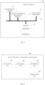
- FIG. 1b is a schematic structural diagram illustrating a mobile terminal according to an embodiment of the present disclosure.
- a mobile terminal 100 includes an application processor (AP) 101, a touch display screen 102, and an optical fingerprint recognition module 103.
- the optical fingerprint recognition module 103 has a fingerprint recognition area located in a first area of the touch display screen 102.
- the AP 101 is coupled with the touch display screen 102 and the optical fingerprint recognition module 103 via a bus 104.
- the optical fingerprint recognition module 103 is configured to collect fingerprint data of a user when the touch display screen 102 detects a touch operation of the user in the first area and send the fingerprint data to the AP 101.
- the first area may be any preset area of the touch display screen 102.
- the preset area may be located at any position of the touch display screen 102, such as, on the upper left side (as illustrated in FIG. 1c ), the upper side, the lower side, the left side, and the right side of the touch display screen 102.
- the size of the preset area is able to be covered by the fingerprint area of the finger.
- the preset area may be any shape, such as, a circular shape, an elliptical shape, a quadrangular shape (e.g., a rectangular shape), a fingerprint-like shape, and so on, which is not limited herein.
- the touch display screen 102 may be a thin film transistor-liquid crystal display (TFT-LCD), a light emitting diode (LED) display, an organic light-emitting diode (OLED) display, or the like.
- TFT-LCD thin film transistor-liquid crystal display
- LED light emitting diode
- OLED organic light-emitting diode
- the touch display screen 102 may include a touch screen and a display screen.
- the touch screen and the display screen are stacked, and the display screen is disposed on a bottom surface of the touch screen.
- the AP 101 is configured to obtain repaired fingerprint data by denoising the fingerprint data according to pre-collected noise data, where the pre-collected noise data is collected in advance by the optical fingerprint recognition module 103 when there is no touch operation in the first area.
- the pre-collected noise data may be collected in advance by the optical fingerprint recognition module 103 before the fingerprint data of the user is collected.
- the optical fingerprint recognition module 103 collects noise data in advance for processing when there is no touch operation in the first area. If the first area is covered with residual foreign material (e.g., a fingerprint mark), the result of the fingerprint data collected by the optical fingerprint recognition module 103 may be affected. Before comparison of fingerprint data, the fingerprint data collected is denoised and repaired to obtain the repaired fingerprint data closer to a real fingerprint.
- the AP 101 is further configured to determine whether the repaired fingerprint data is matched with pre-stored fingerprint template data.
- the AP 101 is further configured to determine that fingerprint verification passes when the repaired fingerprint data is matched with the pre-stored fingerprint template data.
- the AP 101 denoises and repairs the fingerprint data collected to obtain the repaired fingerprint data closer to a real fingerprint.
- the influence of the residual foreign material in the first area (fingerprint recognition area) of the touch display screen on the fingerprint data collected can be reduced, thereby facilitating the success of fingerprint matching.
- the noise data includes N noise-data points
- the fingerprint data includes N fingerprint-data points
- the N noise-data points are in one-to-one correspondence with the N fingerprint-data points.
- the AP 101 configured to obtain the repaired fingerprint data by denoising the fingerprint data according to the pre-collected noise data is configured to: obtain a first data difference between a first noise-data point and a first fingerprint-data point; and obtain a first repaired fingerprint-data point by repairing the first fingerprint-data point according to the first data difference, where the repaired fingerprint data includes N repaired fingerprint-data points, the first noise-data point is any one of the N noise-data points, the first fingerprint-data point is one of the N fingerprint-data points which corresponds to the first noise-data point, and N is an integer greater than or equal to 2.
- the optical fingerprint recognition module 103 can collect N fingerprint-data points of the user upon detecting the touch operation of the user in the first area, and can also collect N noise-data points when there is no touch operation in the first area.
- the N noise-data points are in one-to-one correspondence with the N fingerprint-data points.
- the AP 101 is configured to obtain a first data difference between a first noise-data point of the N noise-data points and a first fingerprint-data point (where the first noise-data point corresponds to the first fingerprint-data point), and obtain a first repaired fingerprint-data point by repairing the first fingerprint-data point according to the first data difference.
- the AP 101 configured to obtain the first repaired fingerprint-data point by repairing the first fingerprint-data point according to the first data difference is configured to: use the first data difference between the first noise-data point and the first fingerprint-data point as a value of the first repaired fingerprint-data point.
- a value of the first noise-data point collected by the optical fingerprint recognition module 103 is 50
- a value of the first fingerprint-data point is 150, that is, the difference between the two is 100, 100 can be used as the value of the first repaired fingerprint-data point.
- the AP 101 configured to obtain the first repaired fingerprint-data point by repairing the first fingerprint-data point according to the first data difference is configured to: determine whether the first data difference is greater than a preset threshold; use the first data difference as a value of the first repaired fingerprint-data point when the first data difference is greater than the preset threshold; or skip the repairing of the first fingerprint-data point when the first data difference is smaller than or equal to the preset threshold.
- the optical fingerprint recognition module 103 collects fingerprint data at two times, there may be a slight difference between the fingerprint data points collected at the two times. If the first data difference is relatively large, it indicates that a first data point is greatly affected by noise or the first data point is data collected at convex portions of a fingerprint (i.e., ridges of the fingerprint), and therefore, the first data point needs to be repaired and the first data difference is used as the value of the first repaired fingerprint-data point. If the first data difference is relatively small, it indicates that the first data point is less affected by noise, and therefore, the first data point does not need to be repaired.
- the preset threshold can be set in advance, for example, the preset threshold can be set to be 5. The complexity of repairing fingerprint data can be reduced, and so the speed of fingerprint comparison can be improved.
- the optical fingerprint recognition module 103 is further configured to periodically collect noise data when there is no touch operation in the first area.
- the optical fingerprint recognition module 103 can periodically collect the noise data, for example, a period is 1 minute, 5 minutes, and like.
- the AP 101 is further configured to obtain the periodically collected noise data from the optical fingerprint recognition module 103, and take most-recently-collected noise data as the pre-collected noise data.
- the AP 101 Each time after obtaining new noise data from the optical fingerprint recognition module 103, the AP 101 overwrites previously obtained noise data with the new noise data to ensure that the last collected noise data is used each time the fingerprint data is repaired, which improves the accuracy of fingerprint repair.
- the pre-collected noise data is any one of multiple noise data periodically collected by the optical fingerprint recognition module when there is no touch operation in the first area.
- FIG. 2 is a schematic flowchart illustrating a method for optical fingerprint recognition according to the present disclosure.
- the method is applicable to a mobile terminal including an AP, a touch display screen, and an optical fingerprint recognition module.
- the optical fingerprint recognition module has a fingerprint recognition area corresponding to a first area of the touch display screen. As illustrated in FIG. 2 , the method may include the following.
- the mobile terminal collects, with the optical fingerprint recognition module, fingerprint data of the user, and sends, with the optical fingerprint recognition module, the fingerprint data to the AP.
- the mobile terminal obtains, with the AP, repaired fingerprint data by denoising the fingerprint data according to pre-collected noise data, where the pre-collected noise data is collected in advance by the optical fingerprint recognition module when there is no touch operation in the first area.
- the mobile terminal determines, with the AP, whether the repaired fingerprint data matches with pre-stored fingerprint template data; when the repaired fingerprint data matches with the pre-stored fingerprint template data, fingerprint verification is successful; when the repaired fingerprint data fails to match with the pre-stored fingerprint template data, the fingerprint verification fails.
- Fingerprint verification may be applicable to scenarios such as fingerprint unlocking and fingerprint payment.
- the AP denoises and repairs the fingerprint data collected to obtain the repaired fingerprint data closer to a real fingerprint.
- the influence of the residual foreign material in the first area (fingerprint recognition area) of the touch display screen on the fingerprint data collected can be reduced, thereby facilitating the success of fingerprint matching.
- the noise data includes N noise-data points
- the fingerprint data includes N fingerprint-data points
- the N noise-data points are in one-to-one correspondence with the N fingerprint-data points
- the mobile terminal obtains, with the AP, the repaired fingerprint data by denoising the fingerprint data according to the pre-collected noise data as follows.
- the mobile terminal obtains, with the AP, a first data difference between a first noise-data point and a first fingerprint-data point.
- the mobile terminal obtains, with the AP, a first repaired fingerprint-data point by repairing the first fingerprint-data point according to the first data difference, where the repaired fingerprint data includes N repaired fingerprint-data points, the first noise-data point is any one of the N noise-data points, the first fingerprint-data point is one of the N fingerprint-data points which corresponds to the first noise-data point, and N is an integer greater than or equal to 2.
- the mobile terminal obtains, with the AP, the first repaired fingerprint-data point by repairing the first fingerprint-data point according to the first data difference as follows.
- the mobile terminal determines, with the AP, whether the first data difference is greater than a preset threshold.
- the mobile terminal uses, with the AP, the first data difference as a value of the first repaired fingerprint-data point.
- the mobile terminal skips, with the AP, the repairing of the first fingerprint-data point.
- the complexity of repairing fingerprint data can be reduced, and so the speed of fingerprint comparison can be improved.
- FIG. 3 is a schematic flowchart illustrating a method for optical fingerprint recognition according to the present disclosure.
- the method is applicable to a mobile terminal including an AP, a touch display screen, and an optical fingerprint recognition module.
- the projection of a fingerprint recognition area of the optical fingerprint recognition module falls on a first area of the touch display screen.
- the method may include the following.
- the mobile terminal collects, with the optical fingerprint recognition module, noise data periodically when there is no touch operation in the first area.
- the mobile terminal collects, with the optical fingerprint recognition module, fingerprint data of the user and sends, with the optical fingerprint recognition module, the fingerprint data to the AP.
- the mobile terminal obtains, with the AP, repaired fingerprint data by denoising the fingerprint data according to pre-collected noise data, where the pre-collected noise data is collected in advance by the optical fingerprint recognition module when there is no touch operation in the first area.
- the pre-collected noise data is any one of multiple noise data periodically collected by the optical fingerprint recognition module when there is no touch operation in the first area.
- the mobile terminal determines, with the AP, whether the repaired fingerprint data is matched with pre-stored fingerprint template data; if the repaired fingerprint data is matched with the pre-stored fingerprint template data, fingerprint verification passes.
- the noise data is periodically collected in advance.
- the AP denoises the fingerprint data collected according to the pre-collected noise data, repairs the fingerprint data collected, and obtains the repaired fingerprint data closer to a real fingerprint.
- the influence of the residual foreign material in the first area (fingerprint recognition area) of the touch display screen on the fingerprint data collected can be reduced, thereby improving success rate of fingerprint matching.
- FIG. 4 is a schematic flowchart illustrating a method for optical fingerprint recognition according to another embodiment of the present disclosure.
- the method is applicable to a mobile terminal including an AP, a touch display screen, and an optical fingerprint recognition module.
- the optical fingerprint recognition module has a fingerprint recognition area located in a first area of the touch display screen. As illustrated in FIG. 4 , the method may include the following.
- the mobile terminal collects, with the optical fingerprint recognition module, noise data periodically when there is no touch operation in the first area.
- the mobile terminal obtains, with the AP, the periodically collected noise data from the optical fingerprint recognition module, and takes, with the AP, most-recently-collected noise data as pre-collected noise data.
- the AP Each time after obtaining new noise data from the optical fingerprint recognition module 103, the AP overwrites previously obtained noise data with the new noise data to ensure that the fingerprint data is repaired using the last collected noise data every time, thereby improving the accuracy of fingerprint repair.
- the mobile terminal collects, with the optical fingerprint recognition module, fingerprint data of the user, and sends, with the optical fingerprint recognition module, the fingerprint data to the AP.
- the mobile terminal obtains, with the AP, repaired fingerprint data by denoising the fingerprint data according to the pre-collected noise data, where the pre-collected noise data is collected in advance by the optical fingerprint recognition module when there is no touch operation in the first area.
- the mobile terminal determines, with the AP, whether the repaired fingerprint data is matched with pre-stored fingerprint template data, and determines, with the AP, that fingerprint verification passes upon determining that the repaired fingerprint data is matched with the pre-stored fingerprint template data.
- the noise data is periodically collected in advance. After the fingerprint data is collected, the AP denoises the fingerprint data collected according to the latest collected noise data, repairs the fingerprint data collected, and obtains the repaired fingerprint data closer to a real fingerprint. The influence of the residual foreign material in the first area (fingerprint recognition area) of the touch display screen on the fingerprint data collected can be reduced, thereby improving success rate of fingerprint matching.
- FIG. 5 is a schematic structural diagram illustrating a mobile terminal.
- a mobile terminal 500 includes an AP 501, a touch display screen 502, an optical fingerprint recognition module 503, a memory 504, and one or more programs.
- the optical fingerprint recognition module has a fingerprint recognition area located in a first area of the touch display screen.
- the AP 501 is coupled with the touch display screen 502, the optical fingerprint recognition module 503, and the memory 504 via a data bus 505.
- One or more programs are stored in the memory 504 and configured to be executed by the AP 501, the one or more programs include instructions configured to: collect fingerprint data of a user when the touch display screen 502 detects a touch operation of the user in the first area and send the fingerprint data to the AP 501; obtain repaired fingerprint data by denoising the fingerprint data according to pre-collected noise data, where the pre-collected noise data is collected in advance by the optical fingerprint recognition module 503 when there is no touch operation in the first area; and determine whether the repaired fingerprint data is matched with pre-stored fingerprint template data, and determine that fingerprint verification passes when the repaired fingerprint data is matched with the pre-stored fingerprint template data.
- the noise data includes N noise-data points
- the fingerprint data includes N fingerprint-data points
- the N noise-data points are in one-to-one correspondence with the N fingerprint-data points
- the instructions of the one or more programs configured to obtain the repaired fingerprint data by denoising the fingerprint data according to the pre-collected noise data are configured to: obtain a first data difference between a first noise-data point and a first fingerprint-data point; and obtain a first repaired fingerprint-data point by repairing the first fingerprint-data point according to the first data difference, where the repaired fingerprint data includes N repaired fingerprint-data points, the first noise-data point is any one of the N noise-data points, the first fingerprint-data point is one of the N fingerprint-data points which corresponds to the first noise-data point, and N is an integer greater than or equal to 2.
- the instructions of the one or more programs configured to obtain the first repaired fingerprint-data point by repairing the first fingerprint-data point according to the first data difference are configured to: determine whether the first data difference is greater than a preset threshold; use the first data difference as a value of the first repaired fingerprint-data point, when the first data difference is greater than the preset threshold; or skip the repairing of the first fingerprint-data point, when the first data difference is smaller than or equal to the preset threshold.
- the one or more programs further include instructions configured to: collect periodically noise data when there is no touch operation in the first area.
- the one or more programs further include instructions configured to: take most-recently-collected noise data as the pre-collected noise data, after collecting periodically the noise data when there is no touch operation in the first area.
- the pre-collected noise data is any one of multiple noise data periodically collected by the optical fingerprint recognition module 503 when there is no touch operation in the first area.
- the AP denoises and repairs the fingerprint data collected to obtain the repaired fingerprint data closer to a real fingerprint.
- the influence of the residual foreign material in the first area (fingerprint recognition area) of the touch display screen on the fingerprint data collected can be reduced, thereby facilitating the success of fingerprint matching.
- FIG. 6 is a schematic structural diagram illustrating a device for optical fingerprint recognition according to an embodiment of the present disclosure.
- a device 600 for optical fingerprint recognition is applicable to a mobile terminal including an AP, a touch display screen, and an optical fingerprint recognition module.
- the optical fingerprint recognition module has a fingerprint recognition area located in a first area of the touch display screen.
- the device 600 includes a collecting unit 601, a processing unit 602, a determining unit 603, and a verification unit 604.
- the collecting unit 601 is configured to control the optical fingerprint recognition module to collect fingerprint data of a user when the touch display screen detects a touch operation of the user in the first area and send the fingerprint data to the AP.
- the processing unit 602 is configured to obtain, with the AP, repaired fingerprint data by denoising the fingerprint data according to pre-collected noise data, where the pre-collected noise data is collected in advance by the optical fingerprint recognition module when there is no touch operation in the first area.
- the determining unit 603 is configured to determine, with the AP, whether the repaired fingerprint data is matched with pre-stored fingerprint template data.
- the verification unit 604 is configured to determine that fingerprint verification passes when the determining unit 603 determines that the repaired fingerprint data is matched with the pre-stored fingerprint template data.
- the processing unit 602 is configured to denoise and repair the fingerprint data collected to obtain the repaired fingerprint data closer to a real fingerprint.
- the influence of the residual foreign material in the first area (fingerprint recognition area) of the touch display screen on the fingerprint data collected can be reduced, thereby facilitating the success of fingerprint matching.
- the noise data includes N noise-data points
- the fingerprint data includes N fingerprint-data points
- the N noise-data points are in one-to-one correspondence with the N fingerprint-data points
- the processing unit 602 configured to obtain, with the AP, the repaired fingerprint data by denoising the fingerprint data according to the pre-collected noise data is configured to: obtain a first data difference between a first noise-data point and a first fingerprint-data point; and obtain a first repaired fingerprint-data point by repairing the first fingerprint-data point according to the first data difference, where the repaired fingerprint data includes N repaired fingerprint-data points, the first noise-data point is any one of the N noise-data points, the first fingerprint-data point is one of the N fingerprint-data points which corresponds to the first noise-data point, and N is an integer greater than or equal to 2.
- the processing unit 602 configured to obtain, with the AP, the first repaired fingerprint-data point by repairing the first fingerprint-data point according to the first data difference is configured to: determine whether the first data difference is greater than a preset threshold; use the first data difference as a value of the first repaired fingerprint-data point, when the first data difference is greater than the preset threshold; or skip the repairing of the first fingerprint-data point, when the first data difference is smaller than or equal to the preset threshold.
- the collecting unit 601 is further configured to periodically collect, with the optical fingerprint recognition module, noise data when there is no touch operation in the first area.
- the device 600 for optical fingerprint recognition further includes an obtaining unit 605.
- the obtaining unit 605 is configured to: obtain, with the AP, the periodically collected noise data from the optical fingerprint recognition module; and take, with the AP, most-recently-collected noise data as the pre-collected noise data.
- the pre-collected noise data is any one of multiple noise data periodically collected by the optical fingerprint recognition module when there is no touch operation in the first area.
- the noise data can be periodically collected in advance. After the fingerprint data is collected, the fingerprint data collected is denoised according to the latest collected noise data, and fingerprint data collected is repaired, so as to obtain the repaired fingerprint data closer to a real fingerprint. The influence of the residual foreign material in the first area (fingerprint recognition area) of the touch display screen on the collected fingerprint data can be reduced, and so success rate of fingerprint matching can be improved.
- the present disclosure further provide another mobile terminal.
- the mobile terminal may be any terminal device, such as a mobile phone, a tablet computer, a personal digital assistant (PDA), a point of sale terminal (POS), an on-board computer and the like.
- PDA personal digital assistant
- POS point of sale terminal
- FIG. 8 is a block diagram of a part of a structure of a mobile phone related to a mobile terminal according to an embodiment of the present disclosure.
- the mobile phone includes a radio frequency (RF) circuit 910, a memory 920, an input unit 930, a display unit 940, a sensor 950, an audio circuit 960, a wireless fidelity (Wi-Fi) module 970, a processor 980, a power supply 990, and other components.
- RF radio frequency
- RF radio frequency
- memory 920 includes a radio frequency (RF) circuit 910, a memory 920, an input unit 930, a display unit 940, a sensor 950, an audio circuit 960, a wireless fidelity (Wi-Fi) module 970, a processor 980, a power supply 990, and other components.
- Wi-Fi wireless fidelity
- FIG. 8 does not constitute any limitation on a mobile phone.
- the mobile phone configured to implement technical solutions of the present disclosure may include more or fewer components than
- the RF circuit 910 is configured to transmit or receive information.
- the RF circuit 910 includes but is not limited to an antenna, at least one amplifier, a transceiver, a coupler, a low noise amplifier (LNA), a duplexer, and the like.
- the RF circuit 910 may also communicate with the network and other devices via wireless communication.
- the above wireless communication may use any communication standard or protocol, which includes but is not limited to global system of mobile communication (GSM), general packet radio service (GPRS), code division multiple access (CDMA), wideband code division multiple access (WCDMA), long term evolution (LTE), E-mail, short messaging service (SMS), and so on.
- GSM global system of mobile communication
- GPRS general packet radio service
- CDMA code division multiple access
- WCDMA wideband code division multiple access
- LTE long term evolution
- E-mail short messaging service
- the memory 920 is configured to store software programs and modules, and the processor 980 is configured to execute various function applications and data processing of the mobile phone by running the software programs and the modules stored in the memory 920.
- the memory 920 mainly includes a program storing region and a data storing region.
- the program storing region may store an operating system, application programs required for at least one function and so on.
- the data storing region may store data created according to use of the mobile phone, and so on.
- the memory 920 may include a high-speed random access memory (RAM), and may further include a non-transitory memory such as at least one disk storage device, a flash device, or other non-transitory solid storage devices.
- the input unit 930 is configured to receive input digital or character information and generate key signal input associated with user setting and function control of the mobile phone.
- the input unit 930 may include a fingerprint recognition module 931 (e.g., an optical fingerprint recognition module), a touch display screen 932, and other input devices 933.
- the fingerprint recognition module 931 can collect fingerprint data of the user.
- the input unit 930 may further include other input devices 933.
- other input devices 933 may include, but not limit to, one or more of a touch screen, a physical key, a function key (such as a volume control key, a switch key, etc.), a trackball, a mouse, a joystick, and the like.
- the display unit 940 is configured to display information input by the user or information provided for the user or various menus of the mobile phone.
- the display unit 940 may include a display screen 941.
- the display screen 941 may be in the form of a liquid crystal display (LCD), an organic light-emitting diode (OLED), and so on.
- the fingerprint recognition module 931 and the display screen 941 are illustrated as two separate components in FIG. 8 to realize the input and output functions of the mobile phone, in some embodiments, the fingerprint recognition module 931 may be integrated with the display screen 941 to implement the input and output functions of the mobile phone.
- the mobile phone may further include at least one sensor 950, such as, a light sensor, a motion sensor, and other sensors.
- the light sensor may include an ambient light sensor and a proximity sensor, the ambient light sensor may adjust the brightness of the display screen 941 according to ambient lights, and the proximity sensor may turn off the display screen 941 and/or backlight when the mobile phone reaches nearby the ear.
- an accelerometer sensor can detect the magnitude of acceleration in all directions (typically three axes) and when the mobile phone is stationary, the accelerometer sensor can detect the magnitude and direction of gravity; the accelerometer sensor can also identify mobile-phone gestures related applications (such as vertical and horizontal screen switch, related games, magnetometer attitude calibration), or the accelerometer sensor can be used for vibration-recognition related functions (such as a pedometer, percussion) and so on.
- the mobile phone can also be equipped with a gyroscope, a barometer, a hygrometer, a thermometer, and an infrared sensor and other sensors, and it will not be repeated herein.
- the audio circuit 960, a speaker 961, and a microphone 962 may provide an audio interface between the user and the mobile phone.
- the audio circuit 960 may convert the received audio data into electrical signals and transfer the electrical signals to the speaker 961; thereafter the speaker 961 converts the electrical signals into sound signals to output.
- the microphone 962 converts received sound signals into electrical signals, which will be received and converted into audio data by the audio circuit 960 to output.
- the audio data is then processed and transmitted by the processor 980 via the RF circuit 910 to another mobile phone for example, or, the audio data is output to the memory 920 for further processing.
- Wi-Fi belongs to a short-range wireless transmission technology.
- the mobile phone may assist the user in E-mail receiving and sending, webpage browsing, access to streaming media and the like.
- Wi-Fi provides users with wireless broadband Internet access.
- the Wi-Fi module 970 is illustrated in FIG. 8 , it should be understood that the Wi-Fi module 970 is not essential to the mobile phone and can be omitted according to actual needs without departing from the essential nature of the present disclosure.
- the processor 980 is a control center of the mobile phone. It uses various interfaces and lines to connect various parts of the whole mobile phone, runs or executes software programs and/or modules stored in the memory 920, and calls data stored in the memory 920 to perform various functions of the mobile phone and process data, thereby monitoring the mobile phone.
- the processor 980 may include one or more processing units; for example, the processor 980 may integrate an application processor and a modem processor, where the application processor mainly handles the operating system, the user interface, the application programs, and so on, and the modem processor mainly processes wireless communication. It will be appreciated that the above-mentioned modem processor may not be integrated into the processor 980.
- the mobile phone also includes the power supply 990 (e.g., a battery) that supplies power to various components.
- the power supply 990 may be logically connected to the processor 980 via a power management system to enable management of charging, discharging, and power consumption through the power management system.
- the mobile phone may include a camera, a Bluetooth module, etc., and the present disclosure will not elaborate herein.
- the present disclosure further provide a computer storage medium.
- the computer storage medium is configured to store computer programs for electronic data interchange, the computer programs are operable with a computer to execute part or all of the operations described in any of the method for optical fingerprint recognition described in the foregoing method embodiments.
- the present disclosure further provide a computer program product.
- the computer program product includes a non-transitory computer readable storage medium which is configured to store computer programs, the computer programs are operable with a computer to execute part or all of the operations described in any of the method for optical fingerprint recognition described in the foregoing method.
Description
- This disclosure relates to the field of data transmission technologies, and more particularly to a method for optical fingerprint recognition and related products.
- With the popularity of mobile terminals such as smart phones, in modern life, almost everybody has a mobile phone. Currently, mobile phones generally adopt a fingerprint recognition technology, and fingerprint recognition can be used in various scenarios such as mobile terminal unlocking, mobile payment, and the like.
- The optical fingerprint recognition technology is widely applied to a fingerprint recognition module of various mobile terminals because of its good stability and high recognition sensitivity. An optical fingerprint recognition module generally includes a light source and an optical fingerprint detection module. An imaging principle of optical fingerprint recognition is as follows: the light source emits lights; the lights pass through a surface of a display screen on which a finger is pressed and then are reflected to the optical fingerprint recognition module; the optical fingerprint recognition module receives and processes the lights reflected to obtain a fingerprint image. A principle of fingerprint comparison is as follows: the optical fingerprint recognition module compares the fingerprint image obtained with a pre-stored fingerprint image to obtain a comparison result.
- However, since a user's finger may easily leave a fingerprint mark when pressing the surface of the display screen, and the residual fingerprint mark often affects a recognition result of the optical fingerprint recognition module, which results in deviation between a collected fingerprint image and a real fingerprint image, thereby reducing fingerprint matching success rate of the optical fingerprint recognition module.
CN 102833423 describes a touch screen mobile phone having fingerprint identification and a login unlocking method for the touch screen mobile phone.CN 105956535 discloses a fingerprint identification control method.CN 101383002 relates to a method for collecting and splicing a fingerprint, which can support rolling in any direction and is a method for identifying and processing a fingerprint picture.CN 106066685 discloses an unlock control method using a fingerprint identification module to determine if a fingerprint image matches with a fingerprint contrast processing result.CN 202196429 is a utility model relating to portable handheld electronic equipment having a fingerprint identification module. - The present invention is defined in the independent claims. According to embodiments of the present disclosure, a method for optical fingerprint recognition and related products are provided, which can improve success rate of fingerprint matching.
- In a first aspect of the present disclosure, a method for optical fingerprint recognition is provided according to the steps of claim 1.
- In a second aspect of the present disclosure, a device according to claim 5 is provided.
- In a third aspect of the present disclosure, a computer-implemented storage medium according to claim 9 is provided. The device can be a mobile terminal which includes an AP, a touch display screen, an optical fingerprint recognition module having a fingerprint recognition area located in a first area of the touch display screen, a memory, and one or more programs stored in the memory and configured to be executed by the AP. The one or more programs comprising instructions configured to: collect fingerprint data of a user when the touch display screen detects a touch operation of the user in the first area and send the fingerprint data to the AP; obtain repaired fingerprint data by denoising the fingerprint data according to pre-collected noise data, where the pre-collected noise data is collected in advance by the optical fingerprint recognition module when there is no touch operation in the first area; and determine whether the repaired fingerprint data is matched with pre-stored fingerprint template data, and determine that fingerprint verification passes when the repaired fingerprint data is matched with the pre-stored fingerprint template data.
- The device includes a collecting unit, a processing unit, a determining unit, and a verification unit. The collecting unit is configured to control the optical fingerprint recognition module to collect fingerprint data of a user when the touch display screen detects a touch operation of the user in the first area and send the fingerprint data to the AP. The processing unit is configured to obtain, with the AP, repaired fingerprint data by denoising the fingerprint data according to pre-collected noise data, where the pre-collected noise data is collected in advance by the optical fingerprint recognition module when there is no touch operation in the first area. The determining unit is configured to determine, with the AP, whether the repaired fingerprint data is matched with pre-stored fingerprint template data. The verification unit is configured to determine that fingerprint verification passes when the determining unit determines that the repaired fingerprint data is matched with the pre-stored fingerprint template data.
- In an example not covered by the claims, a computer program product is also provided.
The computer program product includes a non-transitory computer readable storage medium which is configured to store computer programs, the computer programs are operable with a computer to execute part or all of the operations described in any method of the first aspect of the present disclosure. - According to an example not covered by the claims, before comparison of fingerprint data, the fingerprint data collected is denoised and repaired to obtain the repaired fingerprint data closer to a real fingerprint. According to the invention, the influence of the residual foreign material in the first area (fingerprint recognition area) of the touch display screen on the fingerprint data collected can be reduced, thereby facilitating the success of fingerprint matching.
- In order to describe technical solutions of embodiments of the present disclosure or the related art more clearly, the following will give a brief description of accompanying drawings used for describing the embodiments of the present disclosure or the related art. Apparently, accompanying drawings described below are merely some embodiments of the present disclosure. Those of ordinary skill in the art can also obtain other accompanying drawings based on the accompanying drawings described below without creative efforts.
-
FIG. 1a is a schematic diagram illustrating a working principle of an optical fingerprint recognition module -
FIG. 1b is a schematic structural diagram illustrating a mobile terminal -
FIG. 1c is a schematic structural diagram illustrating a fingerprint recognition area -
FIG. 2 is a schematic flowchart illustrating a method for optical fingerprint recognition -
FIG. 3 is a schematic flowchart illustrating a method for optical fingerprint recognition -
FIG. 4 is a schematic flowchart illustrating a method for optical fingerprint recognition -
FIG. 5 is a schematic structural diagram illustrating a mobile terminal -
FIG. 6 is a schematic structural diagram illustrating a device for optical fingerprint recognition -
FIG. 7 is a schematic structural diagram illustrating a device for optical fingerprint recognition -
FIG. 8 is a schematic structural diagram illustrating a mobile terminal - The mobile terminal involved in the embodiments of the present disclosure may include various handheld devices, on-board devices, wearable devices, computing devices that have wireless communication functions, or other processing devices connected to a wireless modem, as well as various forms of user equipment (UE), mobile stations (MS), terminal devices, and the like. For convenience of description, the above-mentioned devices are collectively referred to as mobile terminals.
- Hereinafter, embodiments of the present disclosure will be described in detail.
- For a better understanding of embodiments of the present disclosure, a working principle of an optical fingerprint recognition module is introduced first.
FIG. 1a is a schematic diagram illustrating a working principle of an optical fingerprint recognition module according to the present disclosure. As illustrated inFIG. 1a , atouch display screen 110 and an opticalfingerprint recognition module 120 are illustrated. The opticalfingerprint recognition module 120 can emit lights, which can be referred to as incident lights. The incident lights pass through an area of the touch display screen that is in contact with a finger, and then are reflected by patterns of the finger. Reflected lights are received by the opticalfingerprint recognition module 120. According to the total reflection (also known as total internal reflection) principle, the opticalfingerprint recognition module 120 can determine which incident lights are projected onto convex portions of a fingerprint (i.e., ridges of the fingerprint) and which incident lights are projected onto concave portions of the fingerprint (i.e., valleys of the fingerprint). - Referring to an enlarged dotted line area of
FIG. 1a , in a surface of the touch display screen, the ridges of the fingerprint are in contact with the surface of the touch display screen, while the valleys of the fingerprint are not. On one hand, when incident lights generated by the opticalfingerprint recognition module 120 are projected onto the valleys of the fingerprint, the incident lights are projected onto a surface of the touch display screen that is in contact with air. In this case, total reflection of the incident lights can be achieved by designing incident angles of the incident lights (a refractive index of the air is approximately equal to 1 and a refractive index of material of the touch display screen is greater than 1, accordingly, the refractive index of the material of the touch display screen is set to be greater than that of the air). In this way, the opticalfingerprint recognition module 120 can receive strong total-reflected lights. On the other hand, when the incident lights generated by the opticalfingerprint recognition module 120 are projected onto the ridges of the fingerprint, the incident lights are projected onto a surface of the touch display screen that is in contact with the convex portions of the fingerprint. In this situation, since the incident lights are projected onto the convex portions of the fingerprint, diffuse reflection occurs. As such, the opticalfingerprint recognition module 120 can receive weak diffuse reflected lights. Therefore, the opticalfingerprint recognition module 120 can obtain a fingerprint image according to received lights of different intensities. -
FIG. 1b is a schematic structural diagram illustrating a mobile terminal according to an embodiment of the present disclosure. As illustrated inFIG. 1b , amobile terminal 100 includes an application processor (AP) 101, atouch display screen 102, and an opticalfingerprint recognition module 103. The opticalfingerprint recognition module 103 has a fingerprint recognition area located in a first area of thetouch display screen 102. TheAP 101 is coupled with thetouch display screen 102 and the opticalfingerprint recognition module 103 via abus 104. - The optical
fingerprint recognition module 103 is configured to collect fingerprint data of a user when thetouch display screen 102 detects a touch operation of the user in the first area and send the fingerprint data to theAP 101. - The first area may be any preset area of the
touch display screen 102. The preset area may be located at any position of thetouch display screen 102, such as, on the upper left side (as illustrated inFIG. 1c ), the upper side, the lower side, the left side, and the right side of thetouch display screen 102. The size of the preset area is able to be covered by the fingerprint area of the finger. The preset area may be any shape, such as, a circular shape, an elliptical shape, a quadrangular shape (e.g., a rectangular shape), a fingerprint-like shape, and so on, which is not limited herein. - The
touch display screen 102 may be a thin film transistor-liquid crystal display (TFT-LCD), a light emitting diode (LED) display, an organic light-emitting diode (OLED) display, or the like. - The
touch display screen 102 may include a touch screen and a display screen. The touch screen and the display screen are stacked, and the display screen is disposed on a bottom surface of the touch screen. - The
AP 101 is configured to obtain repaired fingerprint data by denoising the fingerprint data according to pre-collected noise data, where the pre-collected noise data is collected in advance by the opticalfingerprint recognition module 103 when there is no touch operation in the first area. - The pre-collected noise data may be collected in advance by the optical
fingerprint recognition module 103 before the fingerprint data of the user is collected. The opticalfingerprint recognition module 103 collects noise data in advance for processing when there is no touch operation in the first area. If the first area is covered with residual foreign material (e.g., a fingerprint mark), the result of the fingerprint data collected by the opticalfingerprint recognition module 103 may be affected. Before comparison of fingerprint data, the fingerprint data collected is denoised and repaired to obtain the repaired fingerprint data closer to a real fingerprint. - The
AP 101 is further configured to determine whether the repaired fingerprint data is matched with pre-stored fingerprint template data. - The
AP 101 is further configured to determine that fingerprint verification passes when the repaired fingerprint data is matched with the pre-stored fingerprint template data. - Before comparison of fingerprint data, the
AP 101 denoises and repairs the fingerprint data collected to obtain the repaired fingerprint data closer to a real fingerprint. The influence of the residual foreign material in the first area (fingerprint recognition area) of the touch display screen on the fingerprint data collected can be reduced, thereby facilitating the success of fingerprint matching. - The noise data includes N noise-data points, the fingerprint data includes N fingerprint-data points, and the N noise-data points are in one-to-one correspondence with the N fingerprint-data points. The
AP 101 configured to obtain the repaired fingerprint data by denoising the fingerprint data according to the pre-collected noise data is configured to: obtain a first data difference between a first noise-data point and a first fingerprint-data point; and obtain a first repaired fingerprint-data point by repairing the first fingerprint-data point according to the first data difference, where the repaired fingerprint data includes N repaired fingerprint-data points, the first noise-data point is any one of the N noise-data points, the first fingerprint-data point is one of the N fingerprint-data points which corresponds to the first noise-data point, and N is an integer greater than or equal to 2. - The optical
fingerprint recognition module 103 can collect N fingerprint-data points of the user upon detecting the touch operation of the user in the first area, and can also collect N noise-data points when there is no touch operation in the first area. The N noise-data points are in one-to-one correspondence with the N fingerprint-data points. TheAP 101 is configured to obtain a first data difference between a first noise-data point of the N noise-data points and a first fingerprint-data point (where the first noise-data point corresponds to the first fingerprint-data point), and obtain a first repaired fingerprint-data point by repairing the first fingerprint-data point according to the first data difference. In one embodiment, theAP 101 configured to obtain the first repaired fingerprint-data point by repairing the first fingerprint-data point according to the first data difference is configured to: use the first data difference between the first noise-data point and the first fingerprint-data point as a value of the first repaired fingerprint-data point. For example, a value of the first noise-data point collected by the opticalfingerprint recognition module 103 is 50, and a value of the first fingerprint-data point is 150, that is, the difference between the two is 100, 100 can be used as the value of the first repaired fingerprint-data point. - The
AP 101 configured to obtain the first repaired fingerprint-data point by repairing the first fingerprint-data point according to the first data difference is configured to: determine whether the first data difference is greater than a preset threshold; use the first data difference as a value of the first repaired fingerprint-data point when the first data difference is greater than the preset threshold; or skip the repairing of the first fingerprint-data point when the first data difference is smaller than or equal to the preset threshold. - In general, when the optical
fingerprint recognition module 103 collects fingerprint data at two times, there may be a slight difference between the fingerprint data points collected at the two times. If the first data difference is relatively large, it indicates that a first data point is greatly affected by noise or the first data point is data collected at convex portions of a fingerprint (i.e., ridges of the fingerprint), and therefore, the first data point needs to be repaired and the first data difference is used as the value of the first repaired fingerprint-data point. If the first data difference is relatively small, it indicates that the first data point is less affected by noise, and therefore, the first data point does not need to be repaired. The preset threshold can be set in advance, for example, the preset threshold can be set to be 5. The complexity of repairing fingerprint data can be reduced, and so the speed of fingerprint comparison can be improved. - The optical
fingerprint recognition module 103 is further configured to periodically collect noise data when there is no touch operation in the first area. - The optical
fingerprint recognition module 103 can periodically collect the noise data, for example, a period is 1 minute, 5 minutes, and like. - The
AP 101 is further configured to obtain the periodically collected noise data from the opticalfingerprint recognition module 103, and take most-recently-collected noise data as the pre-collected noise data. - Each time after obtaining new noise data from the optical
fingerprint recognition module 103, theAP 101 overwrites previously obtained noise data with the new noise data to ensure that the last collected noise data is used each time the fingerprint data is repaired, which improves the accuracy of fingerprint repair. - The pre-collected noise data is any one of multiple noise data periodically collected by the optical fingerprint recognition module when there is no touch operation in the first area.
-
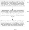
FIG. 2 is a schematic flowchart illustrating a method for optical fingerprint recognition according to the present disclosure. The method is applicable to a mobile terminal including an AP, a touch display screen, and an optical fingerprint recognition module. The optical fingerprint recognition module has a fingerprint recognition area corresponding to a first area of the touch display screen. As illustrated inFIG. 2 , the method may include the following. - At 201, when the touch display screen detects a touch operation of a user in the first area, the mobile terminal collects, with the optical fingerprint recognition module, fingerprint data of the user, and sends, with the optical fingerprint recognition module, the fingerprint data to the AP.
- At 202, the mobile terminal obtains, with the AP, repaired fingerprint data by denoising the fingerprint data according to pre-collected noise data, where the pre-collected noise data is collected in advance by the optical fingerprint recognition module when there is no touch operation in the first area.
- At 203, the mobile terminal determines, with the AP, whether the repaired fingerprint data matches with pre-stored fingerprint template data; when the repaired fingerprint data matches with the pre-stored fingerprint template data, fingerprint verification is successful; when the repaired fingerprint data fails to match with the pre-stored fingerprint template data, the fingerprint verification fails. Fingerprint verification may be applicable to scenarios such as fingerprint unlocking and fingerprint payment.
- Before comparison of fingerprint data, the AP denoises and repairs the fingerprint data collected to obtain the repaired fingerprint data closer to a real fingerprint. The influence of the residual foreign material in the first area (fingerprint recognition area) of the touch display screen on the fingerprint data collected can be reduced, thereby facilitating the success of fingerprint matching.
- The noise data includes N noise-data points, the fingerprint data includes N fingerprint-data points, the N noise-data points are in one-to-one correspondence with the N fingerprint-data points, and the mobile terminal obtains, with the AP, the repaired fingerprint data by denoising the fingerprint data according to the pre-collected noise data as follows. The mobile terminal obtains, with the AP, a first data difference between a first noise-data point and a first fingerprint-data point. The mobile terminal obtains, with the AP, a first repaired fingerprint-data point by repairing the first fingerprint-data point according to the first data difference, where the repaired fingerprint data includes N repaired fingerprint-data points, the first noise-data point is any one of the N noise-data points, the first fingerprint-data point is one of the N fingerprint-data points which corresponds to the first noise-data point, and N is an integer greater than or equal to 2.
- The mobile terminal obtains, with the AP, the first repaired fingerprint-data point by repairing the first fingerprint-data point according to the first data difference as follows. The mobile terminal determines, with the AP, whether the first data difference is greater than a preset threshold. Upon determining that the first data difference is greater than the preset threshold, the mobile terminal uses, with the AP, the first data difference as a value of the first repaired fingerprint-data point. Upon determining that the first data difference is smaller than or equal to the preset threshold, the mobile terminal skips, with the AP, the repairing of the first fingerprint-data point.
- The complexity of repairing fingerprint data can be reduced, and so the speed of fingerprint comparison can be improved.
-
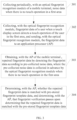
FIG. 3 is a schematic flowchart illustrating a method for optical fingerprint recognition according to the present disclosure. The method is applicable to a mobile terminal including an AP, a touch display screen, and an optical fingerprint recognition module. The projection of a fingerprint recognition area of the optical fingerprint recognition module falls on a first area of the touch display screen. As illustrated inFIG. 3 , the method may include the following. - At 301, the mobile terminal collects, with the optical fingerprint recognition module, noise data periodically when there is no touch operation in the first area.
- At 302, when the touch display screen detects a touch operation of a user in the first area, the mobile terminal collects, with the optical fingerprint recognition module, fingerprint data of the user and sends, with the optical fingerprint recognition module, the fingerprint data to the AP.
- At 303, the mobile terminal obtains, with the AP, repaired fingerprint data by denoising the fingerprint data according to pre-collected noise data, where the pre-collected noise data is collected in advance by the optical fingerprint recognition module when there is no touch operation in the first area.
- In one embodiment, the pre-collected noise data is any one of multiple noise data periodically collected by the optical fingerprint recognition module when there is no touch operation in the first area.
- At 304, the mobile terminal determines, with the AP, whether the repaired fingerprint data is matched with pre-stored fingerprint template data; if the repaired fingerprint data is matched with the pre-stored fingerprint template data, fingerprint verification passes.
- For details of the operations from 302 to 304, reference can be made to the operations from 201 to 203 described in conjunction with in
FIG. 2 , and it will not be repeated here. - Before comparison of fingerprint data, the noise data is periodically collected in advance. After the fingerprint data is collected, the AP denoises the fingerprint data collected according to the pre-collected noise data, repairs the fingerprint data collected, and obtains the repaired fingerprint data closer to a real fingerprint. The influence of the residual foreign material in the first area (fingerprint recognition area) of the touch display screen on the fingerprint data collected can be reduced, thereby improving success rate of fingerprint matching.
-
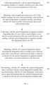
FIG. 4 is a schematic flowchart illustrating a method for optical fingerprint recognition according to another embodiment of the present disclosure. The method is applicable to a mobile terminal including an AP, a touch display screen, and an optical fingerprint recognition module. The optical fingerprint recognition module has a fingerprint recognition area located in a first area of the touch display screen. As illustrated inFIG. 4 , the method may include the following. - At 401, the mobile terminal collects, with the optical fingerprint recognition module, noise data periodically when there is no touch operation in the first area.
- At 402, the mobile terminal obtains, with the AP, the periodically collected noise data from the optical fingerprint recognition module, and takes, with the AP, most-recently-collected noise data as pre-collected noise data.
- Each time after obtaining new noise data from the optical
fingerprint recognition module 103, the AP overwrites previously obtained noise data with the new noise data to ensure that the fingerprint data is repaired using the last collected noise data every time, thereby improving the accuracy of fingerprint repair. - At 403, when the touch display screen detects a touch operation of a user in the first area, the mobile terminal collects, with the optical fingerprint recognition module, fingerprint data of the user, and sends, with the optical fingerprint recognition module, the fingerprint data to the AP.
- At 404, the mobile terminal obtains, with the AP, repaired fingerprint data by denoising the fingerprint data according to the pre-collected noise data, where the pre-collected noise data is collected in advance by the optical fingerprint recognition module when there is no touch operation in the first area.
- At 405, the mobile terminal determines, with the AP, whether the repaired fingerprint data is matched with pre-stored fingerprint template data, and determines, with the AP, that fingerprint verification passes upon determining that the repaired fingerprint data is matched with the pre-stored fingerprint template data.
- For details of the operations from 402 to 405, reference can be made to the operations from 301 to 304 described in conjunction with in
FIG. 3 , and it will not be repeated here. - Before comparison of fingerprint data, the noise data is periodically collected in advance. After the fingerprint data is collected, the AP denoises the fingerprint data collected according to the latest collected noise data, repairs the fingerprint data collected, and obtains the repaired fingerprint data closer to a real fingerprint.
The influence of the residual foreign material in the first area (fingerprint recognition area) of the touch display screen on the fingerprint data collected can be reduced, thereby improving success rate of fingerprint matching. -
FIG. 5 is a schematic structural diagram illustrating a mobile terminal. As illustrated inFIG. 5 , amobile terminal 500 includes anAP 501, atouch display screen 502, an opticalfingerprint recognition module 503, amemory 504, and one or more programs. The optical fingerprint recognition module has a fingerprint recognition area located in a first area of the touch display screen. TheAP 501 is coupled with thetouch display screen 502, the opticalfingerprint recognition module 503, and thememory 504 via adata bus 505. - One or more programs are stored in the
memory 504 and configured to be executed by theAP 501, the one or more programs include instructions configured to: collect fingerprint data of a user when thetouch display screen 502 detects a touch operation of the user in the first area and send the fingerprint data to theAP 501; obtain repaired fingerprint data by denoising the fingerprint data according to pre-collected noise data, where the pre-collected noise data is collected in advance by the opticalfingerprint recognition module 503 when there is no touch operation in the first area; and determine whether the repaired fingerprint data is matched with pre-stored fingerprint template data, and determine that fingerprint verification passes when the repaired fingerprint data is matched with the pre-stored fingerprint template data. - The noise data includes N noise-data points, the fingerprint data includes N fingerprint-data points, the N noise-data points are in one-to-one correspondence with the N fingerprint-data points, and the instructions of the one or more programs configured to obtain the repaired fingerprint data by denoising the fingerprint data according to the pre-collected noise data are configured to: obtain a first data difference between a first noise-data point and a first fingerprint-data point; and obtain a first repaired fingerprint-data point by repairing the first fingerprint-data point according to the first data difference, where the repaired fingerprint data includes N repaired fingerprint-data points, the first noise-data point is any one of the N noise-data points, the first fingerprint-data point is one of the N fingerprint-data points which corresponds to the first noise-data point, and N is an integer greater than or equal to 2.
- The instructions of the one or more programs configured to obtain the first repaired fingerprint-data point by repairing the first fingerprint-data point according to the first data difference are configured to: determine whether the first data difference is greater than a preset threshold; use the first data difference as a value of the first repaired fingerprint-data point, when the first data difference is greater than the preset threshold; or skip the repairing of the first fingerprint-data point, when the first data difference is smaller than or equal to the preset threshold.
- The one or more programs further include instructions configured to: collect periodically noise data when there is no touch operation in the first area.
- The one or more programs further include instructions configured to: take most-recently-collected noise data as the pre-collected noise data, after collecting periodically the noise data when there is no touch operation in the first area.
- The pre-collected noise data is any one of multiple noise data periodically collected by the optical
fingerprint recognition module 503 when there is no touch operation in the first area. - Before comparison of fingerprint data, the AP denoises and repairs the fingerprint data collected to obtain the repaired fingerprint data closer to a real fingerprint. The influence of the residual foreign material in the first area (fingerprint recognition area) of the touch display screen on the fingerprint data collected can be reduced, thereby facilitating the success of fingerprint matching.
-
FIG. 6 is a schematic structural diagram illustrating a device for optical fingerprint recognition according to an embodiment of the present disclosure. Adevice 600 for optical fingerprint recognition is applicable to a mobile terminal including an AP, a touch display screen, and an optical fingerprint recognition module. The optical fingerprint recognition module has a fingerprint recognition area located in a first area of the touch display screen. As illustrated inFIG. 6 , thedevice 600 includes acollecting unit 601, aprocessing unit 602, a determiningunit 603, and averification unit 604. - The collecting
unit 601 is configured to control the optical fingerprint recognition module to collect fingerprint data of a user when the touch display screen detects a touch operation of the user in the first area and send the fingerprint data to the AP. - The
processing unit 602 is configured to obtain, with the AP, repaired fingerprint data by denoising the fingerprint data according to pre-collected noise data, where the pre-collected noise data is collected in advance by the optical fingerprint recognition module when there is no touch operation in the first area. - The determining
unit 603 is configured to determine, with the AP, whether the repaired fingerprint data is matched with pre-stored fingerprint template data. - The
verification unit 604 is configured to determine that fingerprint verification passes when the determiningunit 603 determines that the repaired fingerprint data is matched with the pre-stored fingerprint template data. - Before comparison of fingerprint data, the
processing unit 602 is configured to denoise and repair the fingerprint data collected to obtain the repaired fingerprint data closer to a real fingerprint. The influence of the residual foreign material in the first area (fingerprint recognition area) of the touch display screen on the fingerprint data collected can be reduced, thereby facilitating the success of fingerprint matching. - The noise data includes N noise-data points, the fingerprint data includes N fingerprint-data points, the N noise-data points are in one-to-one correspondence with the N fingerprint-data points, and the
processing unit 602 configured to obtain, with the AP, the repaired fingerprint data by denoising the fingerprint data according to the pre-collected noise data is configured to: obtain a first data difference between a first noise-data point and a first fingerprint-data point; and obtain a first repaired fingerprint-data point by repairing the first fingerprint-data point according to the first data difference, where the repaired fingerprint data includes N repaired fingerprint-data points, the first noise-data point is any one of the N noise-data points, the first fingerprint-data point is one of the N fingerprint-data points which corresponds to the first noise-data point, and N is an integer greater than or equal to 2. - The
processing unit 602 configured to obtain, with the AP, the first repaired fingerprint-data point by repairing the first fingerprint-data point according to the first data difference is configured to: determine whether the first data difference is greater than a preset threshold; use the first data difference as a value of the first repaired fingerprint-data point, when the first data difference is greater than the preset threshold; or skip the repairing of the first fingerprint-data point, when the first data difference is smaller than or equal to the preset threshold. - The collecting
unit 601 is further configured to periodically collect, with the optical fingerprint recognition module, noise data when there is no touch operation in the first area. - As illustrated in
FIG. 7 , thedevice 600 for optical fingerprint recognition further includes an obtainingunit 605. The obtainingunit 605 is configured to: obtain, with the AP, the periodically collected noise data from the optical fingerprint recognition module; and take, with the AP, most-recently-collected noise data as the pre-collected noise data. - The pre-collected noise data is any one of multiple noise data periodically collected by the optical fingerprint recognition module when there is no touch operation in the first area.
- Before comparison of fingerprint data, the noise data can be periodically collected in advance. After the fingerprint data is collected, the fingerprint data collected is denoised according to the latest collected noise data, and fingerprint data collected is repaired, so as to obtain the repaired fingerprint data closer to a real fingerprint. The influence of the residual foreign material in the first area (fingerprint recognition area) of the touch display screen on the collected fingerprint data can be reduced, and so success rate of fingerprint matching can be improved.
- The present disclosure further provide another mobile terminal. As illustrated in
FIG. 8 , only parts of the present disclosure are illustrated for ease of description. For technical details not described, reference may be made to the method of the present disclosure. The mobile terminal may be any terminal device, such as a mobile phone, a tablet computer, a personal digital assistant (PDA), a point of sale terminal (POS), an on-board computer and the like. The following describes a mobile phone as an example of the mobile terminal. -
FIG. 8 is a block diagram of a part of a structure of a mobile phone related to a mobile terminal according to an embodiment of the present disclosure. As illustrated inFIG. 8 , the mobile phone includes a radio frequency (RF)circuit 910, amemory 920, aninput unit 930, adisplay unit 940, asensor 950, anaudio circuit 960, a wireless fidelity (Wi-Fi)module 970, aprocessor 980, apower supply 990, and other components. Those skilled in the art can understand that the structure of the mobile phone illustrated inFIG. 8 does not constitute any limitation on a mobile phone. The mobile phone configured to implement technical solutions of the present disclosure may include more or fewer components than illustrated, or may combine certain components, or may adopt different arrangements of components. - In the following, various components of the mobile phone will be described in detail with reference to
FIG. 8 . - The
RF circuit 910 is configured to transmit or receive information. Generally, theRF circuit 910 includes but is not limited to an antenna, at least one amplifier, a transceiver, a coupler, a low noise amplifier (LNA), a duplexer, and the like. In addition, theRF circuit 910 may also communicate with the network and other devices via wireless communication. The above wireless communication may use any communication standard or protocol, which includes but is not limited to global system of mobile communication (GSM), general packet radio service (GPRS), code division multiple access (CDMA), wideband code division multiple access (WCDMA), long term evolution (LTE), E-mail, short messaging service (SMS), and so on. - The
memory 920 is configured to store software programs and modules, and theprocessor 980 is configured to execute various function applications and data processing of the mobile phone by running the software programs and the modules stored in thememory 920. Thememory 920 mainly includes a program storing region and a data storing region. The program storing region may store an operating system, application programs required for at least one function and so on. The data storing region may store data created according to use of the mobile phone, and so on. In addition, thememory 920 may include a high-speed random access memory (RAM), and may further include a non-transitory memory such as at least one disk storage device, a flash device, or other non-transitory solid storage devices. - The
input unit 930 is configured to receive input digital or character information and generate key signal input associated with user setting and function control of the mobile phone. In one implementation, theinput unit 930 may include a fingerprint recognition module 931 (e.g., an optical fingerprint recognition module), atouch display screen 932, andother input devices 933. Thefingerprint recognition module 931 can collect fingerprint data of the user. In addition to thefingerprint recognition module 931, theinput unit 930 may further includeother input devices 933. In one implementation,other input devices 933 may include, but not limit to, one or more of a touch screen, a physical key, a function key (such as a volume control key, a switch key, etc.), a trackball, a mouse, a joystick, and the like. - The
display unit 940 is configured to display information input by the user or information provided for the user or various menus of the mobile phone. Thedisplay unit 940 may include adisplay screen 941. In at least one implementation, thedisplay screen 941 may be in the form of a liquid crystal display (LCD), an organic light-emitting diode (OLED), and so on. Although thefingerprint recognition module 931 and thedisplay screen 941 are illustrated as two separate components inFIG. 8 to realize the input and output functions of the mobile phone, in some embodiments, thefingerprint recognition module 931 may be integrated with thedisplay screen 941 to implement the input and output functions of the mobile phone. - The mobile phone may further include at least one
sensor 950, such as, a light sensor, a motion sensor, and other sensors. In one implementation, the light sensor may include an ambient light sensor and a proximity sensor, the ambient light sensor may adjust the brightness of thedisplay screen 941 according to ambient lights, and the proximity sensor may turn off thedisplay screen 941 and/or backlight when the mobile phone reaches nearby the ear. As a kind of motion sensor, an accelerometer sensor can detect the magnitude of acceleration in all directions (typically three axes) and when the mobile phone is stationary, the accelerometer sensor can detect the magnitude and direction of gravity; the accelerometer sensor can also identify mobile-phone gestures related applications (such as vertical and horizontal screen switch, related games, magnetometer attitude calibration), or the accelerometer sensor can be used for vibration-recognition related functions (such as a pedometer, percussion) and so on. The mobile phone can also be equipped with a gyroscope, a barometer, a hygrometer, a thermometer, and an infrared sensor and other sensors, and it will not be repeated herein. - The
audio circuit 960, aspeaker 961, and amicrophone 962 may provide an audio interface between the user and the mobile phone. Theaudio circuit 960 may convert the received audio data into electrical signals and transfer the electrical signals to thespeaker 961; thereafter thespeaker 961 converts the electrical signals into sound signals to output. On the other hand, themicrophone 962 converts received sound signals into electrical signals, which will be received and converted into audio data by theaudio circuit 960 to output. The audio data is then processed and transmitted by theprocessor 980 via theRF circuit 910 to another mobile phone for example, or, the audio data is output to thememory 920 for further processing. - Wi-Fi belongs to a short-range wireless transmission technology. With aid of the Wi-
Fi module 970, the mobile phone may assist the user in E-mail receiving and sending, webpage browsing, access to streaming media and the like. Wi-Fi provides users with wireless broadband Internet access. Although the Wi-Fi module 970 is illustrated inFIG. 8 , it should be understood that the Wi-Fi module 970 is not essential to the mobile phone and can be omitted according to actual needs without departing from the essential nature of the present disclosure. - The
processor 980 is a control center of the mobile phone. It uses various interfaces and lines to connect various parts of the whole mobile phone, runs or executes software programs and/or modules stored in thememory 920, and calls data stored in thememory 920 to perform various functions of the mobile phone and process data, thereby monitoring the mobile phone. In at least one implementation, theprocessor 980 may include one or more processing units; for example, theprocessor 980 may integrate an application processor and a modem processor, where the application processor mainly handles the operating system, the user interface, the application programs, and so on, and the modem processor mainly processes wireless communication. It will be appreciated that the above-mentioned modem processor may not be integrated into theprocessor 980. - The mobile phone also includes the power supply 990 (e.g., a battery) that supplies power to various components. For instance, the
power supply 990 may be logically connected to theprocessor 980 via a power management system to enable management of charging, discharging, and power consumption through the power management system. - Although not illustrated, the mobile phone may include a camera, a Bluetooth module, etc., and the present disclosure will not elaborate herein.
- The present disclosure further provide a computer storage medium. The computer storage medium is configured to store computer programs for electronic data interchange, the computer programs are operable with a computer to execute part or all of the operations described in any of the method for optical fingerprint recognition described in the foregoing method embodiments.
- The present disclosure further provide a computer program product. The computer program product includes a non-transitory computer readable storage medium which is configured to store computer programs, the computer programs are operable with a computer to execute part or all of the operations described in any of the method for optical fingerprint recognition described in the foregoing method.
Claims (9)
- A method for optical fingerprint recognition, applicable to a mobile terminal comprising an application processor, AP, a touch display screen, and an optical fingerprint recognition module having a fingerprint recognition area located in a first area of the touch display screen, the method comprising:collecting (201, 302, 403), with the optical fingerprint recognition module, fingerprint data of a user when the touch display screen detects a touch operation of the user in the first area, and sending, with the optical fingerprint recognition module, the fingerprint data to the AP;obtaining (202, 303, 404), with the AP, repaired fingerprint data by denoising the fingerprint data according to pre-collected noise data, wherein the pre-collected noise data is collected in advance by the optical fingerprint recognition module when there is no touch operation in the first area;determining (203, 304, 405), with the AP, whether the repaired fingerprint data is matched with pre-stored fingerprint template data, and determining, with the AP, that fingerprint verification passes upon determining that the repaired fingerprint data is matched with the pre-stored fingerprint template data;the fingerprint data comprising N fingerprint-data points;the pre-collected noise data comprising N noise-data points, and the N noise-data points being in one-to-one correspondence with the N fingerprint-data points;the repaired fingerprint data comprising N denoised fingerprint-data points, N being an integer greater than or equal to 2; andcharacterized in that obtaining, with the AP, the repaired fingerprint data by denoising the fingerprint data according to the pre-collected noise data comprises:
for each of the N noise-data points and each of the N fingerprint-data points:obtaining a data difference between the noise-data point and the fingerprint-data point, the fingerprint-data point being one of the N fingerprint-data points which corresponds to the noise-data point; andif the data difference is greater than a preset threshold, using the data difference as a value of a denoised fingerprint-data point, otherwise skipping the repairing of the fingerprint-data point, the denoised fingerprint-data point being one of the N denoised fingerprint-data points which corresponds to the fingerprint-data point and the noise-data point. - The method of claim 1, further comprising the following prior to collecting, with the optical fingerprint recognition module, the fingerprint data of the user:
collecting periodically (301, 401), with the optical fingerprint recognition module, noise data when there is no touch operation in the first area. - The method of claim 2, further comprising the following after collecting periodically, with the optical fingerprint recognition module, the noise data when there is no touch operation in the first area:obtaining (402), with the AP, the noise data periodically collected from the optical fingerprint recognition module; andtaking (402), with the AP, most-recently-collected noise data as the pre-collected noise data.
- The method of claim 2, wherein the pre-collected noise data is any one of multiple noise data periodically collected by the optical fingerprint recognition module when there is no touch operation in the first area.
- A device (600) for optical fingerprint recognition, comprising an application processor, AP (101), a touch display screen (102), and an optical fingerprint recognition module (103) having a fingerprint recognition area located in a first area of the touch display screen;the optical fingerprint recognition module being configured to collect fingerprint data of a user when the touch display screen detects a touch operation of the user in the first area and send the fingerprint data to the AP;the AP being configured to obtain repaired fingerprint data by denoising the fingerprint data according to pre-collected noise data, wherein the pre-collected noise data is collected in advance by the optical fingerprint recognition module when there is no touch operation in the first area;the AP being further configured to determine whether the repaired fingerprint data is matched with pre-stored fingerprint template data;the AP being further configured to determine that fingerprint verification passes when the repaired fingerprint data is matched with the pre-stored fingerprint template data;the fingerprint data comprising N fingerprint-data points;the pre-collected noise data comprising N noise-data points, and the N noise-data points being in one-to-one correspondence with the N fingerprint-data points;the repaired fingerprint data comprising N denoised fingerprint-data points, N being an integer greater than or equal to 2; andcharacterized in that the AP configured to obtain the repaired fingerprint data by denoising the fingerprint data according to the pre-collected noise data is configured to:
for each of the N noise-data points and each of the N fingerprint-data points:obtain a data difference between the noise-data point and the fingerprint-data point, the fingerprint-data point being one of the N fingerprint-data points which corresponds to the noise-data point; andif the data difference is greater than a preset threshold, use the data difference as a value of a denoised fingerprint-data point, otherwise skip the repairing of the fingerprint-data point, the denoised fingerprint-data point being one of the N denoised fingerprint-data points which corresponds to the fingerprint-data point and the noise-data point. - The device of claim 5, wherein the optical fingerprint recognition module is further configured to periodically collect noise data when there is no touch operation in the first area.
- The device of claim 6, wherein the AP is further configured to:obtain the noise data periodically collected from the optical fingerprint recognition module; andtake most-recently-collected noise data as the pre-collected noise data.
- The device of claim 6, wherein the pre-collected noise data is any one of multiple noise data periodically collected by the optical fingerprint recognition module when there is no touch operation in the first area.
- A computer readable storage medium, configured to store computer programs for electronic data interchange, the computer programs being operable with a computer to execute the method of any of claims 1 to 4.
Applications Claiming Priority (2)
| Application Number | Priority Date | Filing Date | Title |
|---|---|---|---|
| CN201710305567.3A CN107239737A (en) | 2017-05-03 | 2017-05-03 | A kind of optical finger print recognition methods and Related product |
| PCT/CN2018/082210 WO2018201847A1 (en) | 2017-05-03 | 2018-04-08 | Optical fingerprint identification method, and related product |
Publications (3)
| Publication Number | Publication Date |
|---|---|
| EP3620952A1 EP3620952A1 (en) | 2020-03-11 |
| EP3620952A4 EP3620952A4 (en) | 2020-05-20 |
| EP3620952B1 true EP3620952B1 (en) | 2023-06-07 |
Family
ID=59984163
Family Applications (1)
| Application Number | Title | Priority Date | Filing Date |
|---|---|---|---|
| EP18794997.9A Active EP3620952B1 (en) | 2017-05-03 | 2018-04-08 | Optical fingerprint identification method, and related product |
Country Status (4)
| Country | Link |
|---|---|
| US (1) | US20200065555A1 (en) |
| EP (1) | EP3620952B1 (en) |
| CN (1) | CN107239737A (en) |
| WO (1) | WO2018201847A1 (en) |
Families Citing this family (11)
| Publication number | Priority date | Publication date | Assignee | Title |
|---|---|---|---|---|
| CN107239737A (en) * | 2017-05-03 | 2017-10-10 | 广东欧珀移动通信有限公司 | A kind of optical finger print recognition methods and Related product |
| CN110895665B (en) * | 2018-09-12 | 2023-03-31 | 上海耕岩智能科技有限公司 | Coordinate transformation method for under-screen imaging, storage medium and electronic equipment |
| CN109284742A (en) * | 2018-10-30 | 2019-01-29 | Oppo广东移动通信有限公司 | Shield lower fingerprint mould group, electronic equipment and fingerprint image processing method |
| WO2020088156A1 (en) | 2018-10-30 | 2020-05-07 | Oppo广东移动通信有限公司 | Under-screen fingerprint module, electronic device and fingerprint image processing method |
| CN111353332B (en) * | 2018-12-21 | 2023-06-02 | 中国电信股份有限公司 | Fingerprint image processing method, fingerprint image processing device and computer readable storage medium |
| CN111382404B (en) * | 2018-12-27 | 2023-12-29 | 珠海市魅族科技有限公司 | Fingerprint false touch prevention method, system, terminal equipment and readable storage medium |
| CN109740538B (en) * | 2019-01-03 | 2021-07-27 | Oppo广东移动通信有限公司 | Fingerprint acquisition method, electronic device and computer readable storage medium |
| CN111695386B (en) * | 2019-03-15 | 2024-04-26 | 虹软科技股份有限公司 | Fingerprint image enhancement, fingerprint identification and application program starting method |
| CN109976615B (en) * | 2019-03-28 | 2021-03-12 | Oppo广东移动通信有限公司 | Fingerprint image processing method and related device |
| CN110287899B (en) * | 2019-06-27 | 2022-01-11 | Oppo广东移动通信有限公司 | Area fingerprint identification method and related product |
| US11443546B1 (en) * | 2021-04-19 | 2022-09-13 | Novatek Microelectronics Corp. | Fingerprint sensing signal correction method and device thereof |
Family Cites Families (11)
| Publication number | Priority date | Publication date | Assignee | Title |
|---|---|---|---|---|
| AU2779092A (en) * | 1991-10-07 | 1993-05-03 | Cogent Systems, Inc. | Method and system for detecting features of fingerprint in gray level image |
| CN101383002B (en) * | 2008-10-27 | 2010-09-08 | 北京海鑫科金高科技股份有限公司 | Finger print collecting and joining method supporting arbitrary directional rolling |
| CN202196429U (en) * | 2011-07-21 | 2012-04-18 | 德信互动科技(北京)有限公司 | Portable handheld electronic equipment |
| CN102833423B (en) * | 2012-09-24 | 2014-06-04 | 武汉大学 | Touch screen mobile phone based on fingerprint identification and login unlocking method for touch screen mobile phone |
| GB2526874A (en) * | 2014-06-06 | 2015-12-09 | Secr Defence | Synthetic latent fingerprint images |
| US9519819B2 (en) * | 2014-07-14 | 2016-12-13 | Fingerprint Cards Ab | Method and electronic device for noise mitigation |
| CN105205440A (en) * | 2015-02-13 | 2015-12-30 | 比亚迪股份有限公司 | Data processing method for fingerprint sensor and electronic device |
| CN105956535A (en) * | 2016-04-25 | 2016-09-21 | 广东欧珀移动通信有限公司 | Fingerprint identification control method, fingerprint identification control device, and electronic device |
| CN106066685B (en) * | 2016-05-30 | 2018-01-19 | 广东欧珀移动通信有限公司 | One kind solution lock control method and terminal device |
| CN106547309A (en) * | 2016-10-06 | 2017-03-29 | 南昌与德通讯技术有限公司 | Terminal unit and its operational approach |
| CN107239737A (en) * | 2017-05-03 | 2017-10-10 | 广东欧珀移动通信有限公司 | A kind of optical finger print recognition methods and Related product |
-
2017
- 2017-05-03 CN CN201710305567.3A patent/CN107239737A/en active Pending
-
2018
- 2018-04-08 WO PCT/CN2018/082210 patent/WO2018201847A1/en unknown
- 2018-04-08 EP EP18794997.9A patent/EP3620952B1/en active Active
-
2019
- 2019-10-29 US US16/667,342 patent/US20200065555A1/en not_active Abandoned
Also Published As
| Publication number | Publication date |
|---|---|
| WO2018201847A1 (en) | 2018-11-08 |
| EP3620952A4 (en) | 2020-05-20 |
| CN107239737A (en) | 2017-10-10 |
| US20200065555A1 (en) | 2020-02-27 |
| EP3620952A1 (en) | 2020-03-11 |
Similar Documents
| Publication | Publication Date | Title |
|---|---|---|
| EP3620952B1 (en) | Optical fingerprint identification method, and related product | |
| TWI666593B (en) | Optical fingerprint verification method and mobile terminal | |
| US10963660B2 (en) | Method for fingerprint collection and related products | |
| US10963661B2 (en) | Method for optical fingerprint collection and related products | |
| US10169639B2 (en) | Method for fingerprint template update and terminal device | |
| CN106778707B (en) | Fingerprint identification method, display screen and mobile terminal | |
| US11868604B2 (en) | Display processing method and apparatus | |
| WO2017206707A1 (en) | Method for launching application and terminal | |
| US20180314870A1 (en) | Mobile terminal, method and device for displaying fingerprint recognition region | |
| WO2018196500A1 (en) | Electronic device, fingerprint recognition control method and device | |
| CN107463897B (en) | Fingerprint identification method and mobile terminal | |
| WO2016184276A1 (en) | Evaluation method and evaluation device for facial key point positioning result | |
| WO2018161540A1 (en) | Fingerprint registration method and related product | |
| CN107169472B (en) | Fingerprint operation method, mobile terminal and storage medium | |
| CN108304709B (en) | Face unlocking method and related product | |
| CN110706158A (en) | Image processing method, image processing device and terminal equipment | |
| CN110738258B (en) | Image classification method and device and terminal equipment |
Legal Events
| Date | Code | Title | Description |
|---|---|---|---|
| STAA | Information on the status of an ep patent application or granted ep patent |
Free format text: STATUS: THE INTERNATIONAL PUBLICATION HAS BEEN MADE |
|
| PUAI | Public reference made under article 153(3) epc to a published international application that has entered the european phase |
Free format text: ORIGINAL CODE: 0009012 |
|
| STAA | Information on the status of an ep patent application or granted ep patent |
Free format text: STATUS: REQUEST FOR EXAMINATION WAS MADE |
|
| 17P | Request for examination filed |
Effective date: 20191011 |
|
| AK | Designated contracting states |
Kind code of ref document: A1 Designated state(s): AL AT BE BG CH CY CZ DE DK EE ES FI FR GB GR HR HU IE IS IT LI LT LU LV MC MK MT NL NO PL PT RO RS SE SI SK SM TR |
|
| AX | Request for extension of the european patent |
Extension state: BA ME |
|
| A4 | Supplementary search report drawn up and despatched |
Effective date: 20200420 |
|
| RIC1 | Information provided on ipc code assigned before grant |
Ipc: G06K 9/00 20060101AFI20200414BHEP |
|
| DAV | Request for validation of the european patent (deleted) | ||
| DAX | Request for extension of the european patent (deleted) | ||
| STAA | Information on the status of an ep patent application or granted ep patent |
Free format text: STATUS: EXAMINATION IS IN PROGRESS |
|
| 17Q | First examination report despatched |
Effective date: 20211117 |
|
| REG | Reference to a national code |
Ref country code: DE Ref legal event code: R079 Ref document number: 602018051286 Country of ref document: DE Free format text: PREVIOUS MAIN CLASS: G06K0009000000 Ipc: G06V0040120000 Ref country code: DE Free format text: PREVIOUS MAIN CLASS: G06K0009000000 |
|
| GRAP | Despatch of communication of intention to grant a patent |
Free format text: ORIGINAL CODE: EPIDOSNIGR1 |
|
| STAA | Information on the status of an ep patent application or granted ep patent |
Free format text: STATUS: GRANT OF PATENT IS INTENDED |
|
| RIC1 | Information provided on ipc code assigned before grant |
Ipc: G06V 10/30 20220101ALI20230213BHEP Ipc: G06V 40/13 20220101ALI20230213BHEP Ipc: G06V 40/12 20220101AFI20230213BHEP |
|
| INTG | Intention to grant announced |
Effective date: 20230316 |
|
| GRAS | Grant fee paid |
Free format text: ORIGINAL CODE: EPIDOSNIGR3 |
|
| GRAA | (expected) grant |
Free format text: ORIGINAL CODE: 0009210 |
|
| STAA | Information on the status of an ep patent application or granted ep patent |
Free format text: STATUS: THE PATENT HAS BEEN GRANTED |
|
| AK | Designated contracting states |
Kind code of ref document: B1 Designated state(s): AL AT BE BG CH CY CZ DE DK EE ES FI FR GB GR HR HU IE IS IT LI LT LU LV MC MK MT NL NO PL PT RO RS SE SI SK SM TR |
|
| REG | Reference to a national code |
Ref country code: GB Ref legal event code: FG4D |
|
| REG | Reference to a national code |
Ref country code: CH Ref legal event code: EP Ref country code: AT Ref legal event code: REF Ref document number: 1577300 Country of ref document: AT Kind code of ref document: T Effective date: 20230615 |
|
| REG | Reference to a national code |
Ref country code: DE Ref legal event code: R096 Ref document number: 602018051286 Country of ref document: DE |
|
| P01 | Opt-out of the competence of the unified patent court (upc) registered |
Effective date: 20230525 |
|
| REG | Reference to a national code |
Ref country code: LT Ref legal event code: MG9D |
|
| REG | Reference to a national code |
Ref country code: NL Ref legal event code: MP Effective date: 20230607 |
|
| PG25 | Lapsed in a contracting state [announced via postgrant information from national office to epo] |
Ref country code: SE Free format text: LAPSE BECAUSE OF FAILURE TO SUBMIT A TRANSLATION OF THE DESCRIPTION OR TO PAY THE FEE WITHIN THE PRESCRIBED TIME-LIMIT Effective date: 20230607 Ref country code: NO Free format text: LAPSE BECAUSE OF FAILURE TO SUBMIT A TRANSLATION OF THE DESCRIPTION OR TO PAY THE FEE WITHIN THE PRESCRIBED TIME-LIMIT Effective date: 20230907 Ref country code: ES Free format text: LAPSE BECAUSE OF FAILURE TO SUBMIT A TRANSLATION OF THE DESCRIPTION OR TO PAY THE FEE WITHIN THE PRESCRIBED TIME-LIMIT Effective date: 20230607 |
|
| REG | Reference to a national code |
Ref country code: AT Ref legal event code: MK05 Ref document number: 1577300 Country of ref document: AT Kind code of ref document: T Effective date: 20230607 |
|
| PG25 | Lapsed in a contracting state [announced via postgrant information from national office to epo] |
Ref country code: RS Free format text: LAPSE BECAUSE OF FAILURE TO SUBMIT A TRANSLATION OF THE DESCRIPTION OR TO PAY THE FEE WITHIN THE PRESCRIBED TIME-LIMIT Effective date: 20230607 Ref country code: NL Free format text: LAPSE BECAUSE OF FAILURE TO SUBMIT A TRANSLATION OF THE DESCRIPTION OR TO PAY THE FEE WITHIN THE PRESCRIBED TIME-LIMIT Effective date: 20230607 Ref country code: LV Free format text: LAPSE BECAUSE OF FAILURE TO SUBMIT A TRANSLATION OF THE DESCRIPTION OR TO PAY THE FEE WITHIN THE PRESCRIBED TIME-LIMIT Effective date: 20230607 Ref country code: LT Free format text: LAPSE BECAUSE OF FAILURE TO SUBMIT A TRANSLATION OF THE DESCRIPTION OR TO PAY THE FEE WITHIN THE PRESCRIBED TIME-LIMIT Effective date: 20230607 Ref country code: HR Free format text: LAPSE BECAUSE OF FAILURE TO SUBMIT A TRANSLATION OF THE DESCRIPTION OR TO PAY THE FEE WITHIN THE PRESCRIBED TIME-LIMIT Effective date: 20230607 Ref country code: GR Free format text: LAPSE BECAUSE OF FAILURE TO SUBMIT A TRANSLATION OF THE DESCRIPTION OR TO PAY THE FEE WITHIN THE PRESCRIBED TIME-LIMIT Effective date: 20230908 |
|
| PG25 | Lapsed in a contracting state [announced via postgrant information from national office to epo] |
Ref country code: FI Free format text: LAPSE BECAUSE OF FAILURE TO SUBMIT A TRANSLATION OF THE DESCRIPTION OR TO PAY THE FEE WITHIN THE PRESCRIBED TIME-LIMIT Effective date: 20230607 |
|
| PG25 | Lapsed in a contracting state [announced via postgrant information from national office to epo] |
Ref country code: SK Free format text: LAPSE BECAUSE OF FAILURE TO SUBMIT A TRANSLATION OF THE DESCRIPTION OR TO PAY THE FEE WITHIN THE PRESCRIBED TIME-LIMIT Effective date: 20230607 |
|
| PG25 | Lapsed in a contracting state [announced via postgrant information from national office to epo] |
Ref country code: IS Free format text: LAPSE BECAUSE OF FAILURE TO SUBMIT A TRANSLATION OF THE DESCRIPTION OR TO PAY THE FEE WITHIN THE PRESCRIBED TIME-LIMIT Effective date: 20231007 |
|
| PG25 | Lapsed in a contracting state [announced via postgrant information from national office to epo] |
Ref country code: SM Free format text: LAPSE BECAUSE OF FAILURE TO SUBMIT A TRANSLATION OF THE DESCRIPTION OR TO PAY THE FEE WITHIN THE PRESCRIBED TIME-LIMIT Effective date: 20230607 Ref country code: SK Free format text: LAPSE BECAUSE OF FAILURE TO SUBMIT A TRANSLATION OF THE DESCRIPTION OR TO PAY THE FEE WITHIN THE PRESCRIBED TIME-LIMIT Effective date: 20230607 Ref country code: RO Free format text: LAPSE BECAUSE OF FAILURE TO SUBMIT A TRANSLATION OF THE DESCRIPTION OR TO PAY THE FEE WITHIN THE PRESCRIBED TIME-LIMIT Effective date: 20230607 Ref country code: PT Free format text: LAPSE BECAUSE OF FAILURE TO SUBMIT A TRANSLATION OF THE DESCRIPTION OR TO PAY THE FEE WITHIN THE PRESCRIBED TIME-LIMIT Effective date: 20231009 Ref country code: IS Free format text: LAPSE BECAUSE OF FAILURE TO SUBMIT A TRANSLATION OF THE DESCRIPTION OR TO PAY THE FEE WITHIN THE PRESCRIBED TIME-LIMIT Effective date: 20231007 Ref country code: EE Free format text: LAPSE BECAUSE OF FAILURE TO SUBMIT A TRANSLATION OF THE DESCRIPTION OR TO PAY THE FEE WITHIN THE PRESCRIBED TIME-LIMIT Effective date: 20230607 Ref country code: CZ Free format text: LAPSE BECAUSE OF FAILURE TO SUBMIT A TRANSLATION OF THE DESCRIPTION OR TO PAY THE FEE WITHIN THE PRESCRIBED TIME-LIMIT Effective date: 20230607 Ref country code: AT Free format text: LAPSE BECAUSE OF FAILURE TO SUBMIT A TRANSLATION OF THE DESCRIPTION OR TO PAY THE FEE WITHIN THE PRESCRIBED TIME-LIMIT Effective date: 20230607 |
|
| PG25 | Lapsed in a contracting state [announced via postgrant information from national office to epo] |
Ref country code: PL Free format text: LAPSE BECAUSE OF FAILURE TO SUBMIT A TRANSLATION OF THE DESCRIPTION OR TO PAY THE FEE WITHIN THE PRESCRIBED TIME-LIMIT Effective date: 20230607 |
|
| REG | Reference to a national code |
Ref country code: DE Ref legal event code: R097 Ref document number: 602018051286 Country of ref document: DE |
|
| PLBE | No opposition filed within time limit |
Free format text: ORIGINAL CODE: 0009261 |
|
| STAA | Information on the status of an ep patent application or granted ep patent |
Free format text: STATUS: NO OPPOSITION FILED WITHIN TIME LIMIT |
|
| PG25 | Lapsed in a contracting state [announced via postgrant information from national office to epo] |
Ref country code: DK Free format text: LAPSE BECAUSE OF FAILURE TO SUBMIT A TRANSLATION OF THE DESCRIPTION OR TO PAY THE FEE WITHIN THE PRESCRIBED TIME-LIMIT Effective date: 20230607 |
|
| PG25 | Lapsed in a contracting state [announced via postgrant information from national office to epo] |
Ref country code: SI Free format text: LAPSE BECAUSE OF FAILURE TO SUBMIT A TRANSLATION OF THE DESCRIPTION OR TO PAY THE FEE WITHIN THE PRESCRIBED TIME-LIMIT Effective date: 20230607 |