EP3620868B1 - Apparatus, method, program, and recording medium to output recommended control conditions - Google Patents
Apparatus, method, program, and recording medium to output recommended control conditions Download PDFInfo
- Publication number
- EP3620868B1 EP3620868B1 EP19190755.9A EP19190755A EP3620868B1 EP 3620868 B1 EP3620868 B1 EP 3620868B1 EP 19190755 A EP19190755 A EP 19190755A EP 3620868 B1 EP3620868 B1 EP 3620868B1
- Authority
- EP
- European Patent Office
- Prior art keywords
- control condition
- state
- data
- agents
- recommended
- Prior art date
- Legal status (The legal status is an assumption and is not a legal conclusion. Google has not performed a legal analysis and makes no representation as to the accuracy of the status listed.)
- Active
Links
- 238000000034 method Methods 0.000 title claims description 34
- 238000012545 processing Methods 0.000 claims description 77
- 230000006870 function Effects 0.000 claims description 20
- 230000004044 response Effects 0.000 claims description 19
- 239000003795 chemical substances by application Substances 0.000 description 108
- 230000008569 process Effects 0.000 description 24
- 238000004891 communication Methods 0.000 description 16
- 238000010586 diagram Methods 0.000 description 9
- 238000003860 storage Methods 0.000 description 8
- 238000007670 refining Methods 0.000 description 7
- 238000005259 measurement Methods 0.000 description 5
- 230000005540 biological transmission Effects 0.000 description 4
- 238000009826 distribution Methods 0.000 description 4
- 238000012986 modification Methods 0.000 description 4
- 230000004048 modification Effects 0.000 description 4
- 230000008859 change Effects 0.000 description 3
- 239000012535 impurity Substances 0.000 description 3
- 238000004519 manufacturing process Methods 0.000 description 3
- 238000003491 array Methods 0.000 description 2
- 238000013528 artificial neural network Methods 0.000 description 2
- 230000003139 buffering effect Effects 0.000 description 2
- 230000003247 decreasing effect Effects 0.000 description 2
- 230000000694 effects Effects 0.000 description 2
- 230000010365 information processing Effects 0.000 description 2
- 238000010801 machine learning Methods 0.000 description 2
- 238000012544 monitoring process Methods 0.000 description 2
- 230000003287 optical effect Effects 0.000 description 2
- 238000010248 power generation Methods 0.000 description 2
- 230000002787 reinforcement Effects 0.000 description 2
- 230000005856 abnormality Effects 0.000 description 1
- 230000004913 activation Effects 0.000 description 1
- 210000004556 brain Anatomy 0.000 description 1
- 230000015556 catabolic process Effects 0.000 description 1
- 239000002131 composite material Substances 0.000 description 1
- 230000007423 decrease Effects 0.000 description 1
- 238000013135 deep learning Methods 0.000 description 1
- 230000001419 dependent effect Effects 0.000 description 1
- 238000013461 design Methods 0.000 description 1
- 238000005516 engineering process Methods 0.000 description 1
- 230000007613 environmental effect Effects 0.000 description 1
- ZZUFCTLCJUWOSV-UHFFFAOYSA-N furosemide Chemical compound C1=C(Cl)C(S(=O)(=O)N)=CC(C(O)=O)=C1NCC1=CC=CO1 ZZUFCTLCJUWOSV-UHFFFAOYSA-N 0.000 description 1
- 238000012423 maintenance Methods 0.000 description 1
- 238000007726 management method Methods 0.000 description 1
- 238000013507 mapping Methods 0.000 description 1
- 238000010606 normalization Methods 0.000 description 1
- 239000002994 raw material Substances 0.000 description 1
- 238000010223 real-time analysis Methods 0.000 description 1
- 239000004065 semiconductor Substances 0.000 description 1
- 239000010865 sewage Substances 0.000 description 1
- 230000003068 static effect Effects 0.000 description 1
- 238000002945 steepest descent method Methods 0.000 description 1
- 239000000126 substance Substances 0.000 description 1
- 230000007704 transition Effects 0.000 description 1
- XLYOFNOQVPJJNP-UHFFFAOYSA-N water Substances O XLYOFNOQVPJJNP-UHFFFAOYSA-N 0.000 description 1
Images


Classifications
-
- G—PHYSICS
- G06—COMPUTING; CALCULATING OR COUNTING
- G06N—COMPUTING ARRANGEMENTS BASED ON SPECIFIC COMPUTATIONAL MODELS
- G06N3/00—Computing arrangements based on biological models
- G06N3/004—Artificial life, i.e. computing arrangements simulating life
- G06N3/006—Artificial life, i.e. computing arrangements simulating life based on simulated virtual individual or collective life forms, e.g. social simulations or particle swarm optimisation [PSO]
-
- G—PHYSICS
- G05—CONTROLLING; REGULATING
- G05B—CONTROL OR REGULATING SYSTEMS IN GENERAL; FUNCTIONAL ELEMENTS OF SUCH SYSTEMS; MONITORING OR TESTING ARRANGEMENTS FOR SUCH SYSTEMS OR ELEMENTS
- G05B13/00—Adaptive control systems, i.e. systems automatically adjusting themselves to have a performance which is optimum according to some preassigned criterion
- G05B13/02—Adaptive control systems, i.e. systems automatically adjusting themselves to have a performance which is optimum according to some preassigned criterion electric
-
- F—MECHANICAL ENGINEERING; LIGHTING; HEATING; WEAPONS; BLASTING
- F01—MACHINES OR ENGINES IN GENERAL; ENGINE PLANTS IN GENERAL; STEAM ENGINES
- F01K—STEAM ENGINE PLANTS; STEAM ACCUMULATORS; ENGINE PLANTS NOT OTHERWISE PROVIDED FOR; ENGINES USING SPECIAL WORKING FLUIDS OR CYCLES
- F01K23/00—Plants characterised by more than one engine delivering power external to the plant, the engines being driven by different fluids
- F01K23/02—Plants characterised by more than one engine delivering power external to the plant, the engines being driven by different fluids the engine cycles being thermally coupled
- F01K23/06—Plants characterised by more than one engine delivering power external to the plant, the engines being driven by different fluids the engine cycles being thermally coupled combustion heat from one cycle heating the fluid in another cycle
- F01K23/10—Plants characterised by more than one engine delivering power external to the plant, the engines being driven by different fluids the engine cycles being thermally coupled combustion heat from one cycle heating the fluid in another cycle with exhaust fluid of one cycle heating the fluid in another cycle
- F01K23/101—Regulating means specially adapted therefor
-
- G—PHYSICS
- G05—CONTROLLING; REGULATING
- G05B—CONTROL OR REGULATING SYSTEMS IN GENERAL; FUNCTIONAL ELEMENTS OF SUCH SYSTEMS; MONITORING OR TESTING ARRANGEMENTS FOR SUCH SYSTEMS OR ELEMENTS
- G05B13/00—Adaptive control systems, i.e. systems automatically adjusting themselves to have a performance which is optimum according to some preassigned criterion
- G05B13/02—Adaptive control systems, i.e. systems automatically adjusting themselves to have a performance which is optimum according to some preassigned criterion electric
- G05B13/0265—Adaptive control systems, i.e. systems automatically adjusting themselves to have a performance which is optimum according to some preassigned criterion electric the criterion being a learning criterion
-
- G—PHYSICS
- G06—COMPUTING; CALCULATING OR COUNTING
- G06N—COMPUTING ARRANGEMENTS BASED ON SPECIFIC COMPUTATIONAL MODELS
- G06N20/00—Machine learning
-
- G—PHYSICS
- G06—COMPUTING; CALCULATING OR COUNTING
- G06N—COMPUTING ARRANGEMENTS BASED ON SPECIFIC COMPUTATIONAL MODELS
- G06N20/00—Machine learning
- G06N20/10—Machine learning using kernel methods, e.g. support vector machines [SVM]
-
- G—PHYSICS
- G06—COMPUTING; CALCULATING OR COUNTING
- G06N—COMPUTING ARRANGEMENTS BASED ON SPECIFIC COMPUTATIONAL MODELS
- G06N5/00—Computing arrangements using knowledge-based models
- G06N5/01—Dynamic search techniques; Heuristics; Dynamic trees; Branch-and-bound
-
- G—PHYSICS
- G06—COMPUTING; CALCULATING OR COUNTING
- G06N—COMPUTING ARRANGEMENTS BASED ON SPECIFIC COMPUTATIONAL MODELS
- G06N7/00—Computing arrangements based on specific mathematical models
- G06N7/01—Probabilistic graphical models, e.g. probabilistic networks
Definitions
- the present invention relates to an apparatus, a method, a program, and a recording medium.
- a distributed control system in which sensors and manipulated devices are connected via a communication means to a control apparatus controlling these sensors and devices.
- the yield, operational state, alarm occurrence state, and the like of the facility are measured by the sensors, the measurement results are collected via the DCS, and these measurement results are displayed in a monitoring apparatus such as a monitor of a monitoring terminal or an operation board.
- a monitoring apparatus such as a monitor of a monitoring terminal or an operation board.
- the board operator who monitors the operational state of the facility issues instructions for adjusting manipulated devices such as valves to a worker referred to as a field operator.
- Recently, in order to optimize such adjustments of manipulated devices and the like through machine learning technology is being developed whereby control conditions recommended for each manipulated device are calculated and the work in the facility is automated, as shown in Patent Document 1, for example.
- Patent Document 1 Japanese Patent Application Publication No. 2014-174993
- Patent Document US 2010/070098 A1 (STERZING VOLKMAR [DE] ET AL) 18 March 2010 relates to controlling a technical system. Measured states of the system are used as input to learn a model and output a control that is subsequently executed on the system.
- Patent Document WO 2007/121322 A2 (EDSA MICRO CORP [US]; NASLE ALI [US]; NASLE ADIB [US]) 25 October 2007 relates to data acquisition and real-time analysis in an electrical power distribution and transmission system.
- groups of sensors are read out by one data acquisition device per group.
- Patent Document US 2018/024520 A1 (SINHA SUDHI [US] ET AL) 25 January 2018 relates to a building management system comprising an agent manager system.
- the agent manager can create agents that can each read out or write to a group of devices per agent.
- the apparatus may comprise a plurality of agents that each set some devices among a plurality of devices provided in a facility to be target devices.
- Each of the plurality of agents may include a state acquiring section that acquires state data indicating a state of the facility.
- Each of the plurality of agents may include a control condition acquiring section that acquires control condition data indicating a control condition of each target device.
- Each of the plurality of agents may include a learning processing section that uses learning data including the state data and the control condition data to perform learning processing of a model that outputs recommended control condition data indicating a control condition recommended for each target device in response to input of the state data.
- Each learning processing section may perform the learning processing of the model using the learning data and a reward value determined according to a preset reward function.
- Each model may output the recommended control condition data indicating the control condition of each target device recommended for increasing the reward value beyond a reference reward value, in response to input of the state data.
- Each of the plurality of agents may further include a recommended control condition output section that outputs the recommended control condition data obtained by supplying the model with the state data.
- Each recommended control condition output section may use the model to output the recommended control condition data indicating a closest control condition included in a control condition series that is most highly recommended, among a plurality of control condition series obtained by selecting any one control condition from among a plurality of control conditions of the target device at each timing in the future.
- Each of the plurality of agents may further include a control section that controls the target device according to the control condition indicated by the recommended control condition data.
- Each state acquiring section may acquire the state data after the target device has been controlled by the control section.
- the state acquiring sections in at least two agents among the plurality of agents may acquire the state data that is common therebetween.
- the state acquiring section of at least one agent among the plurality of agents may acquire the state data that further includes control condition data indicating a control condition of a device that is not a target device of the at least one agent among the plurality of devices.
- the learning processing section of each agent may perform learning processing using kernel dynamic policy programming for the target device independently from another agent that differs from this agent.
- a collection of target devices of each of the plurality of agents may include only target devices that are not in a collection of target devices of each other agent differing from this agent among the plurality of agents.
- Each of the plurality of agents may set a single device to be the target device.
- a method In the method, a plurality of agents, which each set some devices among a plurality of devices provided in a facility to be target devices, each acquire state data indicating a state of the facility. In the method, the plurality of agents may each acquire control condition data indicating a control condition of each target device. In the method, the plurality of agents may each acquire use learning data including the state data and the control condition data to perform learning processing of a model that outputs recommended control condition data indicating a control condition recommended for each target device in response to input of the state data.
- a program may cause one or more computers to function as a plurality of agents that each set some devices among a plurality of devices provided in a facility to be target devices.
- Each of the plurality of agents may include a state acquiring section that acquires state data indicating a state of the facility.
- Each of the plurality of agents may include a control condition acquiring section that acquires control condition data indicating a control condition of each target device.
- Each of the plurality of agents may include a learning processing section that uses learning data including the state data and the control condition data to perform learning processing of a model that outputs recommended control condition data indicating a control condition recommended for each target device in response to input of the state data.
- a recording medium storing thereon a program.
- the program may cause one or more computers to function as a plurality of agents that each set some devices among a plurality of devices provided in a facility to be target devices.
- Each of the plurality of agents may include a state acquiring section that acquires state data indicating a state of the facility.
- Each of the plurality of agents may include a control condition acquiring section that acquires control condition data indicating a control condition of each target device.
- Each of the plurality of agents may include a learning processing section that uses learning data including the state data and the control condition data to perform learning processing of a model that outputs recommended control condition data indicating a control condition recommended for each target device in response to input of the state data.
- Fig. 1 shows a system 1 according to the present embodiment.
- the system 1 includes a facility 2, a network 3, and an apparatus 4.
- the facility 2 includes a plurality of devices 20.
- the facility 2 may be a plant, or may be a composite apparatus in which a plurality of devices 20 are combined.
- Examples of such a plant include industrial plants relating to chemical or biological industries, plants that manage and control well sources such as gas fields and oil fields and the surrounding areas, plants that manage and control power generation such as hydro, thermal, or nuclear power, plants that manage and control environmental power generation such as solar power and wind power, plants that control water, sewage, and dams, and the like.
- the facility 2 includes a plurality of devices 20 and a plurality of sensors 21.
- Each device 20 is a tool, machine, or apparatus, and as an example, may be an actuator such as a valve, pump, heater, fan, motor, or switch that controls at least one physical quantity such as the pressure, temperature, pH, velocity, flow rate, or the like in a process in the facility 2.
- a switch may change the order of processes in the plant that is the facility 2, for example.
- the devices 20 may each be different types, or at least some of two or more devices 20 may be the same type.
- At least some of the devices 20 may be target devices 20(T) that are learning targets of an agent 41, described further below.
- the devices 20 are controlled in a wired or wireless manner from outside, via the network 3, but the devices 20 may instead be controlled manually.
- Each sensor 21 measures or identifies the state of the facility 2.
- Each sensor 21 may measure or identify operational states such as the yield of the facility 2, the ratio of impurities mixed in, the operational state of each device 20, or an alarm occurrence state.
- the operational state of a device 20 may be expressed by at least one physical quantity such as the pressure, temperature, pH, velocity, and flow rate controlled by the device 20, for example.
- An alarm may be issued in response to an abnormality occurring in the facility 2, and as an example, a sensor 21 identifying an alarm occurrence state may identify there to be an alarm occurrence state in response to a measured value moving beyond at least one of an upper limit value or a lower limit value.
- Each sensor 21 may supply the apparatus 4 with a result of the measurement of identification, via the network 3.
- the network 3 connects each device 20 and sensor 21 in the facility 2 to the apparatus 4, in a manner enabling communication.
- the communication performed within the network 3 at least the communication between the devices 20 and the apparatus 4 may be performed using a wireless communication protocol of the ISA (International Society of Automation), for example, and may be performed using ISA 100, HART (Highway Addressable Remote Transducer) (Registered Trademark), BRAIN (Registered Trademark), FOUNDATION Fieldbus, or PROFIBUS.
- ISA International Society of Automation
- HART Highway Addressable Remote Transducer
- BRAIN Registered Trademark
- FOUNDATION Fieldbus or PROFIBUS.
- the communication between the sensors 21 and the apparatus 4 can also be performed using the above communication protocols.
- the apparatus 4 performs learning for the plurality of devices 20.
- the apparatus 4 may be one or more computers, may be configured as a PC or the like, or may be realized by cloud computing.
- the apparatus 4 includes a reward value acquiring section 40 and a plurality of agents 41.
- the reward value acquiring section 40 acquires reward values used for reinforcement learning by the agents 41, and acquires reward values for evaluating the operational state of the facility 2.
- the reward values may be values determined by a preset reward function.
- the function is mapping that has a rule causing each element of one collection to correspond to each element of another collection with a one-to-one relationship, and may be an expression or table, for example.
- the reward function may output a reward value obtained by evaluating a state, in response to the input of state data indicating this state.
- the reward function may be set by an operator.
- the reward value acquiring section 40 may acquire the reward values from an operator that used the reward function, or may acquire the reward values by inputting the state data from the sensors 21 into the reward function. If the reward value acquiring section 40 inputs the state data into the reward function, the reward function may be stored within the apparatus 4 or may be stored outside the apparatus 4.
- the plurality of agents 41 set some of the devices 20 in the facility 2 to be target devices 20(T).
- Each agent 41 may have one or more target devices 20(T), and the plurality of agents 41 may each have the same number or a different number of target devices 20(T).
- the collection of target devices 20(T) of each of the plurality of agents 41 may include only target devices that are not in the collections of target devices 20 (T) of other agents 41 differing from this agent 41.
- Each collection of target devices 20(T) may be a collection of a plurality of devices 20 included in a single apparatus, or may be a collection of at least some of a plurality of devices 20 included in different apparatuses.
- each agent 41 may set a different single device 20 to be a target device 20(T).
- the number of agents 41 may be the same as the number of devices 20 in the facility 2, in which case each device 20 may be a target device 20(T) of an agent 41. Instead, the number of agents may be less than the number of devices 20 in the facility 2, in which case the facility 2 may include devices 20 that are not target devices 20(T) of an agent 41.
- Each agent 41 includes a state acquiring section 410, a control condition acquiring section 411, a learning processing section 412, a model 415, a recommended control condition output section 416, and a control section 417.
- the state acquiring section 410 acquires the state data indicating the state of the facility 2.
- the state data may include at least one state parameter indicating a result of a measurement or identification by a sensor 21.
- the state acquiring section 410 acquires the state parameter from a sensor 21, but may instead acquire the state parameter from an operator who has checked a sensor 21.
- the state acquiring section 410 may supply the learning processing section 412 and the recommended control condition output section 416 with the acquired state data.
- the control condition acquiring section 411 acquires control condition data indicating a control condition of each target device 20(T).
- the control condition may be a setting value, target value, or manipulation amount input directly to the device 20.
- the control condition acquiring section 411 acquires the control condition data from the control section 417, but may instead acquire the control condition data from the target device 20(T) or from the operator.
- the control condition acquiring section 411 supplies the learning processing section 412 with the acquired control condition data.
- the learning processing section 412 performs learning processing of the model 415, using learning data that includes the state data and the control condition data. As an example in the present embodiment, the learning processing section 412 may perform the learning processing of the model 415 further using the reward values from the reward value acquiring section 40.
- the model 415 outputs recommended control condition data indicating a recommended control condition for each target device 20(T), in response to the input of state data.
- the recommended control condition may be a control condition for increasing the reward value to beyond a reference reward value.
- the reference reward value may be a reward value corresponding to a work state of the facility 2 at a prescribed timing (e.g. the current time), such as a reward value obtained by inputting the state data at this timing into the reward function, or may be a fixed value (e.g. a value obtained by subtracting a tolerance value from the maximum value of the reward value).
- the model 415 may be stored in a server outside the apparatus 4, in association with the agent 41.
- the recommended control condition output section 416 outputs the recommended control condition data obtained by supplying the state data to the model 415.
- the recommended control condition output section 416 supplies the model 415 with the state data and also outputs the recommended control condition data obtained from the model 415 in response to being supplied with the state data.
- the recommended control condition output section 416 may supply the control section 417 with the recommended control condition data.
- the recommended control condition output section 416 may output the recommended control condition data to the outside of the apparatus 4.
- the control section 417 controls the target device 20(T) according to the control condition indicated by the recommended control condition data.
- the control section 417 controls the target device 20(T) according to the control condition indicated by the recommended control condition data by supplying the target device 20(T) with the recommended control condition data.
- a controller (not shown in the drawings) of the target device 20(T) may be interposed between the control section 417 and the target device 20(T).
- the learning processing of the model 415 is performed by each agent 41 using the learning data that includes the state data of the facility 2 and the control condition data of the target device 20(T), and therefore it is possible to reduce the number of computational processes in the learning processing compared to a case where the learning processing of the model 415 is performed using learning data that includes the control condition data of all of the devices 20. Accordingly, the learning of the model 415 can be made to converge, and the control condition data recommended for each target device 20(T) can be acquired by inputting the state data to the obtained model 415.
- the recommended control condition data of each target device 20(T) that is recommended for increasing the reward value beyond the reference reward value is output from the model 415, it is possible to acquire more suitable recommended control condition data by using the model 415. Furthermore, since the recommended control condition output section 416 that supplies the state data to the model 415 and outputs the recommended control condition data is implemented in the apparatus 4, it is possible to acquire the recommended control condition data by inputting the state data to the apparatus 4 and to output the recommended control condition data to a component inside the apparatus 4 or to the outside of the apparatus 4.
- each of the plurality of agents 41 includes only target devices 20(T) that are not in the collections of target devices 20(T) of the other agents 41, it is possible to perform the learning processing while distributing the processing for a plurality of devices 20 among the agents 41. Accordingly, it is possible to prevent the learning processing that is redundant for some of the devices 20, to reduce the number of computational processes. Furthermore, since the correspondence to the learning content is lower than in a case where learning is performed in a redundant manner for the same device 20 by a plurality of agents 41, it is possible to realize each agent 41 with an individual PC and to efficiently perform distributed processing. Yet further, it is possible to use PCs with low machine power by performing this distributed processing.
- each agent 41 sets a single device 20 to be a target device 20(T)
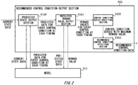
- Fig. 2 shows the model 415 and the recommended control condition output section 416.
- the model 415 may store a history of the state data input thereto.
- the history includes at least the state data at one timing.
- the model 415 may output a probability distribution of predicted state data indicating the predicted state of the facility 2 at each of a plurality of future timings (t +1 ), (t +2 ), etc., where the suffixes "+1" and "+2" are identifiers and larger values indicate later timings, in response to state data being newly input.
- the plurality of future timings (t +1 ), (t +2 ), etc. may be timings at every unit time (e.g. 30 seconds) within a reference time period (e.g. 10 minutes) from the current timing.
- the predicted state data may display the predicted state of the facility 2 in a case where any of the controls indicated by the control conditions (C 1 ), (C 2 ), etc. are performed on a target device 20(T) at each timing (t +1 ), (t +2 ), etc.
- the predicted state data may comprehensively include the predicted state data (D(C 1_t+1 )), (D(C 1_t+2 )), etc.
- the model 415 may output the reward value predicted in a case where the state of the facility 2 is the state indicated by the predicted state data, for every piece of predicted state data. For example, the model 415 may output the reward value in response to the selection of a piece of predicted state data that is predicted in response to the input of the current state data, or may output the reward value in response to the input of the predicted state data.
- the recommended control condition output section 416 uses the model 415 to output the recommended control condition data indicating the control condition that is closest in the future relative to the current timing included in a control condition series that is most highly recommended among a plurality of control condition series obtained by selecting one control condition (C N ) (where N is any natural number) from among the plurality of control conditions (C 1 ), (C 2 ), etc. of the target device 20(T) at each future timing (t +1 ), (t +2 ), etc.
- the recommended control condition output section 416 includes a predicted state output section 4160, a predicted reward value output section 4161, a control condition series specifying section 4162, and a recommended control condition specifying section 4163.
- the predicted state output section 4160 outputs the predicted state data (D) for every control condition (C 1 ), (C 2 ), etc. at each future timing (t +1 ), (t +2 ), etc. to the predicted reward value output section 4161.
- the predicted state output section 4160 may input the current state data to the model 415, acquire, from the model 415, a probability distribution of the predicted state data (D) in cases where any of the controls indicated by the control conditions (C 1 ), (C 2 ), etc. are to be performed on a device 20 at each future timing (t +1 ), (t +2 ), etc., and output this probability distribution to the predicted reward value output section 4161.
- the predicted reward value output section 4161 outputs a reward value for every control condition (C 1 ), (C 2 ), etc. at each future timing (t +1 ), (t +2 ), etc. to the control condition series specifying section 4162.
- the predicted reward value output section 4161 may sequentially input to the model 415 the pieces of predicted state data (D) for every control condition (C 1 ), (C 2 ), etc. at each timing (t +1 ), (t +2 ), etc., sequentially acquire, from the model 415, reward values predicted for cases where and the facility 2 has entered a state indicated by this predicted state data (D), and output these reward values to the control condition series specifying section 4162.
- the control condition series specifying section 4162 generates a plurality of control condition series (C N_t+1 ), (C N_t+2 ), etc. obtained by selecting any one control condition (C N ) at each future timing (t +1 ), (t +2 ), etc.
- the control condition series specifying section 4162 generates a plurality of control condition sequences (control condition series) by selecting and linking together one control condition (C N ) at every timing (t +1 ), (t +2 ), etc.
- the control condition series specifying section 4162 specifies a control condition series having the highest total of predicted reward values corresponding to the control conditions, as an example of the control condition series that is most highly recommended among the plurality of control conditions series.
- the recommended control condition specifying section 4163 specifies the control condition (C N_t+1 ) that is closest in the future to the current timing, among the control conditions at each timing included in the specified control condition series, and outputs the control condition data indicating this control condition (C N_t+1 ) as the recommended control condition data.
- the recommended control condition data indicating the closest control condition (C N ) included in the control condition series that is most highly recommended, among the control conditions obtained by selecting any one control condition (C N ) at each future timing (t +1 ), (t +2 ), etc., and therefore it is possible to acquire the recommended control condition data that is most highly recommended while taking into consideration a plurality of control conditions at each future timing. Furthermore, by performing the control of the target device 20(T) using such recommended control condition data, it is possible to gradually transition the state of the facility 2 to the most highly recommended state at each future timing.
- Fig. 3 shows the operation of the apparatus 4 according to the present embodiment.
- the apparatus 4 performs learning of the model 415 while causing the facility 2 to operate, by performing the processes of steps S1 to S11.
- each control section 417 of each of the plurality of agents 41 controls the target device 20(T) by outputting the control condition data.
- each control section 417 may control the corresponding target device 20(T) with the control condition data indicating the control condition set by the operator.
- each control section 417 may control the corresponding target device 20(T) using this recommended control condition data.
- the state acquiring section 410 of each of the plurality of agents 41 acquires the state data indicating the current state of the facility 2. In this way, the state data after the target device 20(T) has been controlled by the control section 417 is acquired.
- the state acquiring sections 410 of at least two agents 41 among the plurality of agents 41 may acquire common state data.
- these state acquiring sections 410 may acquire state data from at least one common sensor 21, and as an example, all of the state acquiring sections 410 may acquire the state data from all of the sensors 21 within the facility 2.
- the state data acquired by the state acquiring section 410 of at least one agent 41 may include, as a state parameter, control condition data indicating a control condition of at least one other device 20 that is not a target device 20(T) among the plurality of devices 20 in the facility 2.
- the state acquiring section 410 may acquire the control condition data from the control section 417 of an agent 41 other than the agent 41 including this state acquiring section 410.
- the control condition of the other device 20 may be the current control condition, or may be the control conditions at one or more timings in the past (e.g. one control condition immediately prior to the current timing).
- step S5 the control condition acquiring section 411 of each of the plurality of agents 41 acquires the control condition data of the target device 20(T) from step S1.
- the process of step S5 may be performed before step S1, or may be performed between step S1 and step S3.
- the reward value acquiring section 40 acquires the reward value for evaluating the current operational state of the facility 2.
- the reward function may include a parameter concerning at least one of the quality, manufacturing cost, yield, ratio of impurities mixed in, and energy consumed by the facility 2 for the object manufactured by the facility 2.
- the parameter concerning quality may be a maximum value in a case where the quality of the manufactured object is a specified quality, and the specified quality does not necessarily need to be the highest quality.
- the parameter concerning the manufacturing cost may be set according to the price of the raw material.
- the learning processing section 412 of each of the plurality of agents 41 performs the learning processing of the model 415 using the reward value and the learning data that includes the state data and the control condition data.
- the learning processing section 412 of each agent 41 may perform the learning processing using kernel dynamic policy programming (KDPP) for a target device 20(T) independently from other agents 41 that differ from this agent 41.
- KDPP kernel dynamic policy programming
- the learning processing is performed using factorial KDPP for all of the target devices 20(T) of the agents 41, by all of the plurality of agents 41.
- the learning processing in which all of the devices 20 in the facility 2 are target devices 20(T) is performed by one agent 41 using KDPP, it is possible to reduce the number of target devices 20(T) and to reduce the number of computational processes.
- each learning processing section 412 may perform the learning processing using the steepest descent method, a neural network, a DQN (deep Q-network), a Gaussian process, deep learning, or the like. Furthermore, each learning processing section 412 may perform the learning processing without using the reward values, in which case the process of step S7 does not need to be performed. If each agent 41 is realized by an individual PC, these PCs may perform the learning processing of step S9 in a stand-alone state. In this way, there is no need to connect these PCs to a network for communication or the like, and it is possible to reduce the load of processes relating to the network in each PC.
- the recommended control condition output section 416 of each of the plurality of agents 41 outputs to the control section 417 the recommended control condition data obtained by supplying the current state data to the model 415, and moves the process to step S1.
- the target device 20(T) is controlled according to the recommended control condition data and the learning process is repeated, to optimize the operational state of the facility 2.
- the period of step 1 may be set according to a time constant of the facility 2, and may be set to 30 seconds, for example.
- the number of devices 20 and sensors 21 in the facility 2 may be increased or decreased due to maintenance, expansion, breakdown, and the like.
- the number of agents 41 may also be increased or decreased.
- the target device 20(T) is controlled according to the recommended control condition data and the state data corresponding to this control is acquired, and therefore the learning processing of the model 415 is performed further using the learning data that includes the recommended control condition data and the state data corresponding to this recommended control condition data. Accordingly, it is possible to increase the learning accuracy by sequentially performing the learning processing of the model 415 in a case where the control is performed according to the recommended control condition data.
- agents 41 Since state data common among at least two agents 41 is used in the learning processing, the control result of a target device 20(T) by one agent 41 is indirectly reflected in the learning processing of the target device 20(T) by the other agent 41. Accordingly, agents 41 that set some of the devices 20 in the facility 2 to be target devices 20(T) can indirectly cooperate with each other, and it is possible to perform the learning processing to optimize the control conditions of each target device 20(T).
- the control result of the target device 20(T) of the one agent 41 is indirectly reflected in the learning processing performed by the other agent 41, and therefore it is possible to obtain more suitable control conditions for the recommended control conditions recommended to the other agent 41.
- control condition data of another device 20 that is not a target device 20(T) is included in the state data and used in the learning processing, it is possible to improve the learning accuracy compared to a case where the control condition data of this other device 20 is not included in the state data.
- the state data of a target device 20(T) of one agent 41 is affected by the control of another device 20 that is not a target device 20(T)
- the control condition of this other device 20 is indirectly reflected in the learning processing performed by this one agent 41, and therefore it is possible to obtain more suitable control conditions for the recommended control conditions recommended to the one agent 41.
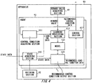
- Fig. 4 shows an apparatus 4A according to a modification.
- the apparatus 4A may further include a refining section 42 that narrows down the state parameters of the state data acquired by each agent 41.
- the refining section 42 may exclude any state parameters, among a plurality of state parameters that are acquisition targets of the state acquiring sections 410 of the agents 41, from being acquisition targets, based on a correlation probability among the plurality of state parameters included in the state data.
- the plurality of state parameters may include at least one of a measurement result obtained by each sensor, an identification result obtained by each sensor 21, and a control condition of each device 20.
- the refining section 42 may exclude state parameters having a correlation probability with the control condition of the target device 20(T) of an agent 41 that is lower than a reference probability, among the plurality of state parameters that are acquisition targets of the state acquiring sections 410 of the agents 41, from the acquisition targets.
- the refining section 42 may stop the acquisition of a state parameter by supplying the state acquiring section 410 of each agent 41 with identification information of this state parameter to be excluded from the acquisition targets.
- the apparatus 4A described above it is possible to narrow down the state parameters in each agent 41 and perform the learning process, thereby making it possible to converge the learning in a short time. Furthermore, the learning can be caused to converge in a manner to be globally optimal across a plurality of devices 20 having defined correlation probabilities.
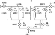
- Fig. 5 shows a portion of a piping instrumentation diagram of the facility 2.
- the facility 2 includes pipes 200(1) to 200(9), flowmeters S(1) to S(5) serving as the sensors 21, and valves V(1) to V(4) serving as the devices 20.
- One end of the pipe 200(1) is connected to one end of the pipe 200(2) and one end of the pipe 200(3), the other ends of the pipes 200(2) and 200(3) are connected to one end of the pipe 200(4).
- One end of the pipe 200(5) is connected to one end of the pipe 200(6) and one end of the pipe 200(7), the other ends of the pipes 200(6) and 200(7) are connected to one end of the pipe 200(8).
- the other ends of the pipes 200(4) and 200(8) are connected to one end of the pipe 200(9).
- the flowmeters S(1) and S(2) are respectively provided in the pipes 200(1) and 200(5), and measure the flow rates thereof.
- the flowmeters S(3) and S(4) are respectively provided in the pipes 200(4) and 200(8), and measure the flow rates thereof.
- the flowmeter S(5) is provided at the connection portion between the pipes 200(4), 200(8), and 200(9), and measures the flow rate in this connection portion.
- the valves V(1) to V(4) are respectively provided in the pipes 200(2), 200(3), 200(6), and 200(7), and adjust the flow rates thereof.
- the refining section 42 may stop the acquisition of certain state parameters by supplying, to the state acquiring section 410 of each agent 41, identification information of the state parameters estimated by the operator or the like to have correlation probabilities with respect to the control condition of the target device 20(T) of this agent 41 that are lower than a reference probability.
- the refining section 42 may supply the learning processing sections 412 with a model of the correspondence between a plurality of state parameters of the facility 2.
- each learning processing section 412 may perform learning processing of the model 415 using the relation model to calculate the correlation probability (Bayesian probability) between state parameters.
- each learning processing section 412 may stop the acquisition of state parameters by supplying the state acquiring section 410 of the agent 41 with the identification information of state parameters for which the correlation probability with respect to the control condition of the target device 20(T) of the agent 41 has been calculated to be less than the reference probability. In this case, it is possible to more reliably cause the learning to converge in a manner to be globally optimal, compared to a case where the state parameters are excluded from the acquisition targets based on an estimation made by the operator.
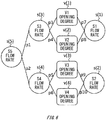
- Fig. 6 shows a relation model between state parameters in the facility 2 of Fig. 5 .
- each conditional parameter is expressed by one of the nodes s(1) to s(5) and (1) to v(4), and related nodes are connected to each other by edges.
- a correlation probability pi to p10 between the nodes connected by the edge is associated with each edge.
- the initial value may be 1 for all of the correlation probabilities pi to p10, and may be changed according to the results of the learning processing.
- the nodes s(1) to s(5) indicate the flow rates measured by the flowmeters S(1) to S(5)
- the nodes v(1) to v(4) indicate the opening degrees of the valves V(1) to V(4).
- Each learning processing section 412 may calculate the correlation probability between state parameters using such a relation model. For example, the learning processing section 412 may calculate the correlation probability between the state parameters by learning whether there is a possibility of the flow rate measured by any of the flow meters S among the flow meters S(1) to S(5) changing significantly, for example, when the valve opening degree of any one of the valves V(1) to V(4) is changed.
- the facility 2 includes the sensors 21, but the sensors 21 do not need to be included in the facility 2.
- the state acquiring section 410 of the apparatus 4 may acquire the state data (e.g. a pressure value indicated by a dial when a mechanical pressure meter is used) from an operator who has checked the state of the facility 2.
- the apparatus 4 described above includes the reward value acquiring section 40, but the apparatus 4 does not need to include the reward value acquiring section 40.
- the learning processing section 412 of each agent 41 may acquire the reward values by inputting the state data into the reward function.
- Each agent 41 described above includes a recommended control condition output section 416 and a control section 417, but may omit at least one of these section. If each agent 41 does not include the recommended control condition output section 416, the model 415 on which the learning processing section 412 performs the learning processing may be connected to another apparatus and used in the operation of the facility 2. If each agent 41 does not include the control section 417, the operator may manually control the target device 20(T) of each agent 41 according to the recommended control condition data output from the recommended control condition output section 416 of this agent 41.
- Various embodiments of the present invention may be described with reference to flowcharts and block diagrams whose blocks may represent (1) steps of processes in which operations are performed or (2) sections of apparatuses responsible for performing operations. Certain steps and sections may be implemented by dedicated circuitry, programmable circuitry supplied with computer-readable instructions stored on computer-readable media, and/or processors supplied with computer-readable instructions stored on computer-readable media.
- Dedicated circuitry may include digital and/or analog hardware circuits and may include integrated circuits (IC) and/or discrete circuits.
- Programmable circuitry may include reconfigurable hardware circuits comprising logical AND, OR, XOR, NAND, NOR, and other logical operations, flip-flops, registers, memory elements, etc., such as field-programmable gate arrays (FPGA), programmable logic arrays (PLA), and the like.
- FPGA field-programmable gate arrays
- PLA programmable logic arrays
- the computer-readable medium may be a tangible device that can store instructions to be executed by a suitable device, and as a result, a computer-readable medium having instructions stored thereon is a product that includes instructions that can be executed in order to create the means for executing the operations designated by flow charts and block diagrams.
- Examples of the computer-readable medium may include an electronic storage device, a magnetic storage device, an optical storage device, an electromagnetic storage medium, a magnetic storage medium, an optical storage medium, an electromagnetic storage medium, a semiconductor storage medium, and the like.
- the computer-readable medium may include a floppy (Registered Trademark) disk, a diskette, a hard disk, a random access memory (RAM), a read-only memory (ROM), an erasable programmable read-only memory (EPROM or Flash memory), an electrically erasable programmable read-only memory (EEPROM), a static random access memory (SRAM), a portable compact disc read-only memory (CD-ROM), a digital versatile disk (DVD), a Blu-ray (Registered Trademark) disk, a memory stick, an integrated circuit card, or the like.
- a floppy (Registered Trademark) disk a diskette, a hard disk, a random access memory (RAM), a read-only memory (ROM), an erasable programmable read-only memory (EPROM or Flash memory), an electrically erasable programmable read-only memory (EEPROM), a static random access memory (SRAM), a portable compact disc read-only memory (CD-ROM), a digital versatile disk
- the computer-readable instructions may be assembler instructions, instruction-set-architecture (ISA) instructions, machine instructions, machine dependent instructions, microcode, firmware instructions, state-setting data, or either source code or object code written in any combination of one or more programming languages, including an object oriented programming language such as Smalltalk, JAVA (Registered Trademark), C++ or the like, and conventional procedural programming languages, such as the "C" programming language or similar programming languages.
- ISA instruction-set-architecture
- machine instructions machine dependent instructions
- microcode firmware instructions
- state-setting data or either source code or object code written in any combination of one or more programming languages, including an object oriented programming language such as Smalltalk, JAVA (Registered Trademark), C++ or the like, and conventional procedural programming languages, such as the "C" programming language or similar programming languages.
- the computer-readable instructions may be provided to a processor or programmable circuitry of a general purpose computer, special purpose computer, or other programmable data processing apparatus to produce a machine, either locally, via a local area network (LAN), or via a wide area network (WAN) such as the Internet, and may be executed to create the means for performing the operations designated by the flow charts and block diagrams.
- the processor include a computer processor, a processing unit, a microprocessor, a digital signal processor, a controller, a microcontroller, and the like.
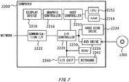
- Fig. 7 shows an example of a computer 2200 in which aspects of the present invention may be wholly or partly embodied.
- a program that is installed in the computer 2200 can cause the computer 2200 to function as or perform operations associated with apparatuses of the embodiments of the present invention or one or more sections thereof, and/or cause the computer 2200 to perform processes of the embodiments of the present invention or steps thereof.
- Such a program may be executed by the CPU 2212 to cause the computer 2200 to perform certain operations associated with some or all of the blocks of flowcharts and block diagrams described herein.
- the computer 2200 includes a CPU 2212, a RAM 2214, a graphic controller 2216, and a display device 2218, which are mutually connected by a host controller 2210.
- the computer 2200 also includes input/output units such as a communication interface 2222, a hard disk drive 2224, a DVD-ROM drive 2226 and an IC card drive, which are connected to the host controller 2210 via an input/output controller 2220.
- the computer also includes legacy input/output units such as a ROM 2230 and a keyboard 2242, which are connected to the input/output controller 2220 through an input/output chip 2240.
- the CPU 2212 operates according to programs stored in the ROM 2230 and the RAM 2214, thereby controlling each unit.
- the graphic controller 2216 obtains image data generated by the CPU 2212 on a frame buffer or the like provided in the RAM 2214 or in itself, and causes the image data to be displayed on the display device 2218.
- the communication interface 2222 communicates with other electronic devices via a network.
- the hard disk drive 2224 stores programs and data used by the CPU 2212 within the computer 2200.
- the DVD-ROM drive 2226 reads the programs or the data from the DVD-ROM 2201, and provides the hard disk drive 2224 with the programs or the data via the RAM 2214.
- the IC card drive reads programs and data from an IC card, and/or writes programs and data into the IC card.
- the ROM 2230 stores therein a boot program or the like executed by the computer 2200 at the time of activation, and/or a program depending on the hardware of the computer 2200.
- the input/output chip 2240 may also connect various input/output units via a parallel port, a serial port, a keyboard port, a mouse port, and the like to the input/output controller 2220.
- a program is provided by computer readable media such as the DVD-ROM 2201 or the IC card.
- the program is read from the computer readable media, installed into the hard disk drive 2224, RAM 2214, or ROM 2230, which are also examples of computer readable media, and executed by the CPU 2212.
- the information processing described in these programs is read into the computer 2200, resulting in cooperation between a program and the above-mentioned various types of hardware resources.
- An apparatus or method may be constituted by realizing the operation or processing of information in accordance with the usage of the computer 2200.
- the CPU 2212 may execute a communication program loaded onto the RAM 2214 to instruct communication processing to the communication interface 2222, based on the processing described in the communication program.
- the communication interface 2222 under control of the CPU 2212, reads transmission data stored on a transmission buffering region provided in a recording medium such as the RAM 2214, the hard disk drive 2224, the DVD-ROM 2201, or the IC card, and transmits the read transmission data to a network or writes reception data received from a network to a reception buffering region or the like provided on the recording medium.
- the CPU 2212 may cause all or a necessary portion of a file or a database to be read into the RAM 2214, the file or the database having been stored in an external recording medium such as the hard disk drive 2224, the DVD-ROM drive 2226 (DVD-ROM 2201), the IC card, etc., and perform various types of processing on the data on the RAM 2214.
- the CPU 2212 may then write back the processed data to the external recording medium.
- the CPU 2212 may perform various types of processing on the data read from the RAM 2214, which includes various types of operations, processing of information, condition judging, conditional branch, unconditional branch, search/replace of information, etc., as described throughout this disclosure and designated by an instruction sequence of programs, and writes the result back to the RAM 2214.
- the CPU 2212 may search for information in a file, a database, etc., in the recording medium.
- the CPU 2212 may search for an entry matching the condition whose attribute value of the first attribute is designated, from among the plurality of entries, and read the attribute value of the second attribute stored in the entry, thereby obtaining the attribute value of the second attribute associated with the first attribute satisfying the predetermined condition.
- the above-explained program or software modules may be stored in the computer readable media on or near the computer 2200.
- a recording medium such as a hard disk or a RAM provided in a server system connected to a dedicated communication network or the Internet can be used as the computer readable media, thereby providing the program to the computer 2200 via the network.
Description
- The present invention relates to an apparatus, a method, a program, and a recording medium.
- Conventionally, in a facility such as a plant, advanced automated work is realized using a distributed control system (DCS) in which sensors and manipulated devices are connected via a communication means to a control apparatus controlling these sensors and devices. In such a facility, the yield, operational state, alarm occurrence state, and the like of the facility are measured by the sensors, the measurement results are collected via the DCS, and these measurement results are displayed in a monitoring apparatus such as a monitor of a monitoring terminal or an operation board. If the yield of the facility is to be increased, for example, the board operator who monitors the operational state of the facility issues instructions for adjusting manipulated devices such as valves to a worker referred to as a field operator. Recently, in order to optimize such adjustments of manipulated devices and the like through machine learning, technology is being developed whereby control conditions recommended for each manipulated device are calculated and the work in the facility is automated, as shown in
Patent Document 1, for example. - Patent Document 1: Japanese Patent Application Publication No.
2014-174993 - Patent Document
US 2010/070098 A1 (STERZING VOLKMAR [DE] ET AL) 18 March 2010 relates to controlling a technical system. Measured states of the system are used as input to learn a model and output a control that is subsequently executed on the system. - Patent Document
WO 2007/121322 A2 (EDSA MICRO CORP [US]; NASLE ALI [US]; NASLE ADIB [US]) 25 October 2007 relates to data acquisition and real-time analysis in an electrical power distribution and transmission system. In an embodiment, groups of sensors are read out by one data acquisition device per group. - Patent Document
US 2018/024520 A1 (SINHA SUDHI [US] ET AL) 25 January 2018 relates to a building management system comprising an agent manager system. The agent manager can create agents that can each read out or write to a group of devices per agent. - However, when simply performing machine learning, there are a huge number of parameters to be learned, the time needed until the learning converges is unrealistically long, and there are cases where the learning docs not converge, and therefore it is impossible to calculate the control conditions recommended for the manipulated devices.
- The invention is defined by the features of the independent claims. Any reference to inventions or embodiments not falling within the scope of the independent claims are to be interpreted as examples useful for understanding the invention.
- According to a first aspect of the present invention, provided is an apparatus. The apparatus may comprise a plurality of agents that each set some devices among a plurality of devices provided in a facility to be target devices. Each of the plurality of agents may include a state acquiring section that acquires state data indicating a state of the facility. Each of the plurality of agents may include a control condition acquiring section that acquires control condition data indicating a control condition of each target device. Each of the plurality of agents may include a learning processing section that uses learning data including the state data and the control condition data to perform learning processing of a model that outputs recommended control condition data indicating a control condition recommended for each target device in response to input of the state data.
- Each learning processing section may perform the learning processing of the model using the learning data and a reward value determined according to a preset reward function. Each model may output the recommended control condition data indicating the control condition of each target device recommended for increasing the reward value beyond a reference reward value, in response to input of the state data.
- Each of the plurality of agents may further include a recommended control condition output section that outputs the recommended control condition data obtained by supplying the model with the state data.
- Each recommended control condition output section may use the model to output the recommended control condition data indicating a closest control condition included in a control condition series that is most highly recommended, among a plurality of control condition series obtained by selecting any one control condition from among a plurality of control conditions of the target device at each timing in the future.
- Each of the plurality of agents may further include a control section that controls the target device according to the control condition indicated by the recommended control condition data. Each state acquiring section may acquire the state data after the target device has been controlled by the control section.
- The state acquiring sections in at least two agents among the plurality of agents may acquire the state data that is common therebetween.
- The state acquiring section of at least one agent among the plurality of agents may acquire the state data that further includes control condition data indicating a control condition of a device that is not a target device of the at least one agent among the plurality of devices.
- The learning processing section of each agent may perform learning processing using kernel dynamic policy programming for the target device independently from another agent that differs from this agent.
- A collection of target devices of each of the plurality of agents may include only target devices that are not in a collection of target devices of each other agent differing from this agent among the plurality of agents.
- Each of the plurality of agents may set a single device to be the target device.
- According to a second aspect of the present invention, provided is a method. In the method, a plurality of agents, which each set some devices among a plurality of devices provided in a facility to be target devices, each acquire state data indicating a state of the facility. In the method, the plurality of agents may each acquire control condition data indicating a control condition of each target device. In the method, the plurality of agents may each acquire use learning data including the state data and the control condition data to perform learning processing of a model that outputs recommended control condition data indicating a control condition recommended for each target device in response to input of the state data.
- According to a third aspect of the present invention, provided is a program. The program may cause one or more computers to function as a plurality of agents that each set some devices among a plurality of devices provided in a facility to be target devices. Each of the plurality of agents may include a state acquiring section that acquires state data indicating a state of the facility. Each of the plurality of agents may include a control condition acquiring section that acquires control condition data indicating a control condition of each target device. Each of the plurality of agents may include a learning processing section that uses learning data including the state data and the control condition data to perform learning processing of a model that outputs recommended control condition data indicating a control condition recommended for each target device in response to input of the state data.
- According to a fourth aspect of the present invention, provided is a recording medium storing thereon a program. The program may cause one or more computers to function as a plurality of agents that each set some devices among a plurality of devices provided in a facility to be target devices. Each of the plurality of agents may include a state acquiring section that acquires state data indicating a state of the facility. Each of the plurality of agents may include a control condition acquiring section that acquires control condition data indicating a control condition of each target device. Each of the plurality of agents may include a learning processing section that uses learning data including the state data and the control condition data to perform learning processing of a model that outputs recommended control condition data indicating a control condition recommended for each target device in response to input of the state data.
- The summary clause does not necessarily describe all necessary features of the embodiments of the present invention. The present invention may also be a sub-combination of the features described above.
-
-
Fig. 1 shows asystem 1 according to the present embodiment. -
Fig. 2 shows themodel 415 and the recommended controlcondition output section 416. -
Fig. 3 shows the operation of theapparatus 4 according to the present embodiment. -
Fig. 4 shows anapparatus 4A according to a modification. -
Fig. 5 shows a portion of a piping instrumentation diagram of thefacility 2. -
Fig. 6 shows a relation model between state parameters in thefacility 2 ofFig. 5 . -
Fig. 7 shows an example of acomputer 2200 in which aspects of the present invention may be wholly or partly embodied. - Hereinafter, some embodiments of the present invention will be described.
-
Fig. 1 shows asystem 1 according to the present embodiment. Thesystem 1 includes afacility 2, anetwork 3, and anapparatus 4. - The
facility 2 includes a plurality ofdevices 20. For example, thefacility 2 may be a plant, or may be a composite apparatus in which a plurality ofdevices 20 are combined. Examples of such a plant include industrial plants relating to chemical or biological industries, plants that manage and control well sources such as gas fields and oil fields and the surrounding areas, plants that manage and control power generation such as hydro, thermal, or nuclear power, plants that manage and control environmental power generation such as solar power and wind power, plants that control water, sewage, and dams, and the like. As an example in the present embodiment, thefacility 2 includes a plurality ofdevices 20 and a plurality ofsensors 21. - Each
device 20 is a tool, machine, or apparatus, and as an example, may be an actuator such as a valve, pump, heater, fan, motor, or switch that controls at least one physical quantity such as the pressure, temperature, pH, velocity, flow rate, or the like in a process in thefacility 2. A switch may change the order of processes in the plant that is thefacility 2, for example. Thedevices 20 may each be different types, or at least some of two ormore devices 20 may be the same type. At least some of thedevices 20 may be target devices 20(T) that are learning targets of anagent 41, described further below. As an example in the present embodiment, thedevices 20 are controlled in a wired or wireless manner from outside, via thenetwork 3, but thedevices 20 may instead be controlled manually. - Each
sensor 21 measures or identifies the state of thefacility 2. Eachsensor 21 may measure or identify operational states such as the yield of thefacility 2, the ratio of impurities mixed in, the operational state of eachdevice 20, or an alarm occurrence state. The operational state of adevice 20 may be expressed by at least one physical quantity such as the pressure, temperature, pH, velocity, and flow rate controlled by thedevice 20, for example. An alarm may be issued in response to an abnormality occurring in thefacility 2, and as an example, asensor 21 identifying an alarm occurrence state may identify there to be an alarm occurrence state in response to a measured value moving beyond at least one of an upper limit value or a lower limit value. Eachsensor 21 may supply theapparatus 4 with a result of the measurement of identification, via thenetwork 3. - The
network 3 connects eachdevice 20 andsensor 21 in thefacility 2 to theapparatus 4, in a manner enabling communication. In the communication performed within thenetwork 3, at least the communication between thedevices 20 and theapparatus 4 may be performed using a wireless communication protocol of the ISA (International Society of Automation), for example, and may be performed using ISA 100, HART (Highway Addressable Remote Transducer) (Registered Trademark), BRAIN (Registered Trademark), FOUNDATION Fieldbus, or PROFIBUS. The communication between thesensors 21 and theapparatus 4 can also be performed using the above communication protocols. - The
apparatus 4 performs learning for the plurality ofdevices 20. Theapparatus 4 may be one or more computers, may be configured as a PC or the like, or may be realized by cloud computing. Theapparatus 4 includes a rewardvalue acquiring section 40 and a plurality ofagents 41. - The reward
value acquiring section 40 acquires reward values used for reinforcement learning by theagents 41, and acquires reward values for evaluating the operational state of thefacility 2. The reward values may be values determined by a preset reward function. Here, the function is mapping that has a rule causing each element of one collection to correspond to each element of another collection with a one-to-one relationship, and may be an expression or table, for example. The reward function may output a reward value obtained by evaluating a state, in response to the input of state data indicating this state. The reward function may be set by an operator. The rewardvalue acquiring section 40 may acquire the reward values from an operator that used the reward function, or may acquire the reward values by inputting the state data from thesensors 21 into the reward function. If the rewardvalue acquiring section 40 inputs the state data into the reward function, the reward function may be stored within theapparatus 4 or may be stored outside theapparatus 4. - The plurality of
agents 41 set some of thedevices 20 in thefacility 2 to be target devices 20(T). Eachagent 41 may have one or more target devices 20(T), and the plurality ofagents 41 may each have the same number or a different number of target devices 20(T). The collection of target devices 20(T) of each of the plurality ofagents 41 may include only target devices that are not in the collections of target devices 20 (T) ofother agents 41 differing from thisagent 41. Each collection of target devices 20(T) may be a collection of a plurality ofdevices 20 included in a single apparatus, or may be a collection of at least some of a plurality ofdevices 20 included in different apparatuses. If a plurality of target devices 20(T) are set for asingle agent 41, these target devices 20(T) may have a relationship to be controlled in conjunction with each other (e.g. a master-slave relationship or a relationship where these target devices 20(T) are not controlled independently). Eachagent 41 may set a differentsingle device 20 to be a target device 20(T). As an example, the number ofagents 41 may be the same as the number ofdevices 20 in thefacility 2, in which case eachdevice 20 may be a target device 20(T) of anagent 41. Instead, the number of agents may be less than the number ofdevices 20 in thefacility 2, in which case thefacility 2 may includedevices 20 that are not target devices 20(T) of anagent 41. - Each
agent 41 includes astate acquiring section 410, a controlcondition acquiring section 411, alearning processing section 412, amodel 415, a recommended controlcondition output section 416, and acontrol section 417. - The
state acquiring section 410 acquires the state data indicating the state of thefacility 2. The state data may include at least one state parameter indicating a result of a measurement or identification by asensor 21. As an example in the present embodiment, thestate acquiring section 410 acquires the state parameter from asensor 21, but may instead acquire the state parameter from an operator who has checked asensor 21. Thestate acquiring section 410 may supply thelearning processing section 412 and the recommended controlcondition output section 416 with the acquired state data. - The control
condition acquiring section 411 acquires control condition data indicating a control condition of each target device 20(T). The control condition may be a setting value, target value, or manipulation amount input directly to thedevice 20. As an example in the present embodiment, the controlcondition acquiring section 411 acquires the control condition data from thecontrol section 417, but may instead acquire the control condition data from the target device 20(T) or from the operator. The controlcondition acquiring section 411 supplies thelearning processing section 412 with the acquired control condition data. - The
learning processing section 412 performs learning processing of themodel 415, using learning data that includes the state data and the control condition data. As an example in the present embodiment, thelearning processing section 412 may perform the learning processing of themodel 415 further using the reward values from the rewardvalue acquiring section 40. - The
model 415 outputs recommended control condition data indicating a recommended control condition for each target device 20(T), in response to the input of state data. The recommended control condition may be a control condition for increasing the reward value to beyond a reference reward value. The reference reward value may be a reward value corresponding to a work state of thefacility 2 at a prescribed timing (e.g. the current time), such as a reward value obtained by inputting the state data at this timing into the reward function, or may be a fixed value (e.g. a value obtained by subtracting a tolerance value from the maximum value of the reward value). Themodel 415 may be stored in a server outside theapparatus 4, in association with theagent 41. - The recommended control
condition output section 416 outputs the recommended control condition data obtained by supplying the state data to themodel 415. In other words, the recommended controlcondition output section 416 supplies themodel 415 with the state data and also outputs the recommended control condition data obtained from themodel 415 in response to being supplied with the state data. The recommended controlcondition output section 416 may supply thecontrol section 417 with the recommended control condition data. The recommended controlcondition output section 416 may output the recommended control condition data to the outside of theapparatus 4. - The
control section 417 controls the target device 20(T) according to the control condition indicated by the recommended control condition data. For example, thecontrol section 417 controls the target device 20(T) according to the control condition indicated by the recommended control condition data by supplying the target device 20(T) with the recommended control condition data. A controller (not shown in the drawings) of the target device 20(T) may be interposed between thecontrol section 417 and the target device 20(T). - According to the
system 1 described above, the learning processing of themodel 415 is performed by eachagent 41 using the learning data that includes the state data of thefacility 2 and the control condition data of the target device 20(T), and therefore it is possible to reduce the number of computational processes in the learning processing compared to a case where the learning processing of themodel 415 is performed using learning data that includes the control condition data of all of thedevices 20. Accordingly, the learning of themodel 415 can be made to converge, and the control condition data recommended for each target device 20(T) can be acquired by inputting the state data to the obtainedmodel 415. - Since the recommended control condition data of each target device 20(T) that is recommended for increasing the reward value beyond the reference reward value is output from the
model 415, it is possible to acquire more suitable recommended control condition data by using themodel 415. Furthermore, since the recommended controlcondition output section 416 that supplies the state data to themodel 415 and outputs the recommended control condition data is implemented in theapparatus 4, it is possible to acquire the recommended control condition data by inputting the state data to theapparatus 4 and to output the recommended control condition data to a component inside theapparatus 4 or to the outside of theapparatus 4. - In a case where the collection of target devices 20(T) of each of the plurality of
agents 41 includes only target devices 20(T) that are not in the collections of target devices 20(T) of theother agents 41, it is possible to perform the learning processing while distributing the processing for a plurality ofdevices 20 among theagents 41. Accordingly, it is possible to prevent the learning processing that is redundant for some of thedevices 20, to reduce the number of computational processes. Furthermore, since the correspondence to the learning content is lower than in a case where learning is performed in a redundant manner for thesame device 20 by a plurality ofagents 41, it is possible to realize eachagent 41 with an individual PC and to efficiently perform distributed processing. Yet further, it is possible to use PCs with low machine power by performing this distributed processing. - In the case where each
agent 41 sets asingle device 20 to be a target device 20(T), it is possible to reduce the number of computational processes of eachagent 41, compared to a case where eachagent 41 sets a plurality ofdevices 20 as target devices 20(T). -
Fig. 2 shows themodel 415 and the recommended controlcondition output section 416. - As an example in the present embodiment, the
model 415 may store a history of the state data input thereto. The history includes at least the state data at one timing. Themodel 415 may output a probability distribution of predicted state data indicating the predicted state of thefacility 2 at each of a plurality of future timings (t+1), (t+2), etc., where the suffixes "+1" and "+2" are identifiers and larger values indicate later timings, in response to state data being newly input. - Here, the plurality of future timings (t+1), (t+2), etc. may be timings at every unit time (e.g. 30 seconds) within a reference time period (e.g. 10 minutes) from the current timing. The predicted state data may display the predicted state of the
facility 2 in a case where any of the controls indicated by the control conditions (C1), (C2), etc. are performed on a target device 20(T) at each timing (t+1), (t+2), etc. As an example, the predicted state data may comprehensively include the predicted state data (D(C1_t+1)), (D(C1_t+2)), etc. (where the suffixes "t+1" and "t+2" indicate the timings at which the control is to be performed) in cases where the controls of the control conditions (C1_t+1), (C1_t+2), etc. are to be performed at the timing (t+1), the predicted state data (D(C1_t+2)), (D(C2_t+2)), etc. in a case where the controls of the control conditions (C1_t+2), (C2_t+2), etc. are to be performed at the timing (t+2), and the like. The probability mentioned above is the degree of the possibility of an event occurring, and may be the percentage chance of this event occurring or a value (relative value) corresponding to this percentage. - The
model 415 may output the reward value predicted in a case where the state of thefacility 2 is the state indicated by the predicted state data, for every piece of predicted state data. For example, themodel 415 may output the reward value in response to the selection of a piece of predicted state data that is predicted in response to the input of the current state data, or may output the reward value in response to the input of the predicted state data. - The recommended control
condition output section 416 uses themodel 415 to output the recommended control condition data indicating the control condition that is closest in the future relative to the current timing included in a control condition series that is most highly recommended among a plurality of control condition series obtained by selecting one control condition (CN) (where N is any natural number) from among the plurality of control conditions (C1), (C2), etc. of the target device 20(T) at each future timing (t+1), (t+2), etc. The recommended controlcondition output section 416 includes a predictedstate output section 4160, a predicted rewardvalue output section 4161, a control conditionseries specifying section 4162, and a recommended controlcondition specifying section 4163. - The predicted
state output section 4160 outputs the predicted state data (D) for every control condition (C1), (C2), etc. at each future timing (t+1), (t+2), etc. to the predicted rewardvalue output section 4161. For example, the predictedstate output section 4160 may input the current state data to themodel 415, acquire, from themodel 415, a probability distribution of the predicted state data (D) in cases where any of the controls indicated by the control conditions (C1), (C2), etc. are to be performed on adevice 20 at each future timing (t+1), (t+2), etc., and output this probability distribution to the predicted rewardvalue output section 4161. - The predicted reward
value output section 4161 outputs a reward value for every control condition (C1), (C2), etc. at each future timing (t+1), (t+2), etc. to the control conditionseries specifying section 4162. For example, the predicted rewardvalue output section 4161 may sequentially input to themodel 415 the pieces of predicted state data (D) for every control condition (C1), (C2), etc. at each timing (t+1), (t+2), etc., sequentially acquire, from themodel 415, reward values predicted for cases where and thefacility 2 has entered a state indicated by this predicted state data (D), and output these reward values to the control conditionseries specifying section 4162. - The control condition
series specifying section 4162 generates a plurality of control condition series (CN_t+1), (CN_t+2), etc. obtained by selecting any one control condition (CN) at each future timing (t+1), (t+2), etc. In other words, the control conditionseries specifying section 4162 generates a plurality of control condition sequences (control condition series) by selecting and linking together one control condition (CN) at every timing (t+1), (t+2), etc. Furthermore, the control conditionseries specifying section 4162 specifies a control condition series having the highest total of predicted reward values corresponding to the control conditions, as an example of the control condition series that is most highly recommended among the plurality of control conditions series. - The recommended control
condition specifying section 4163 specifies the control condition (CN_t+1) that is closest in the future to the current timing, among the control conditions at each timing included in the specified control condition series, and outputs the control condition data indicating this control condition (CN_t+1) as the recommended control condition data. - According to the recommended control
condition output section 416 described above, the recommended control condition data indicating the closest control condition (CN) included in the control condition series that is most highly recommended, among the control conditions obtained by selecting any one control condition (CN) at each future timing (t+1), (t+2), etc., and therefore it is possible to acquire the recommended control condition data that is most highly recommended while taking into consideration a plurality of control conditions at each future timing. Furthermore, by performing the control of the target device 20(T) using such recommended control condition data, it is possible to gradually transition the state of thefacility 2 to the most highly recommended state at each future timing. -
Fig. 3 shows the operation of theapparatus 4 according to the present embodiment. Theapparatus 4 performs learning of themodel 415 while causing thefacility 2 to operate, by performing the processes of steps S1 to S11. - First, at step S1, the
control section 417 of each of the plurality ofagents 41 controls the target device 20(T) by outputting the control condition data. For example, eachcontrol section 417 may control the corresponding target device 20(T) with the control condition data indicating the control condition set by the operator. At step S11 described further below, when the recommended control condition data is output by the recommended controlcondition output section 416, eachcontrol section 417 may control the corresponding target device 20(T) using this recommended control condition data. - At step S3, the
state acquiring section 410 of each of the plurality ofagents 41 acquires the state data indicating the current state of thefacility 2. In this way, the state data after the target device 20(T) has been controlled by thecontrol section 417 is acquired. Here, thestate acquiring sections 410 of at least twoagents 41 among the plurality ofagents 41 may acquire common state data. For example, thesestate acquiring sections 410 may acquire state data from at least onecommon sensor 21, and as an example, all of thestate acquiring sections 410 may acquire the state data from all of thesensors 21 within thefacility 2. The state data acquired by thestate acquiring section 410 of at least oneagent 41 may include, as a state parameter, control condition data indicating a control condition of at least oneother device 20 that is not a target device 20(T) among the plurality ofdevices 20 in thefacility 2. In this case, thestate acquiring section 410 may acquire the control condition data from thecontrol section 417 of anagent 41 other than theagent 41 including thisstate acquiring section 410. The control condition of theother device 20 may be the current control condition, or may be the control conditions at one or more timings in the past (e.g. one control condition immediately prior to the current timing). - At step S5, the control
condition acquiring section 411 of each of the plurality ofagents 41 acquires the control condition data of the target device 20(T) from step S1. The process of step S5 may be performed before step S1, or may be performed between step S1 and step S3. - At step S7, the reward
value acquiring section 40 acquires the reward value for evaluating the current operational state of thefacility 2. Here, the reward function may include a parameter concerning at least one of the quality, manufacturing cost, yield, ratio of impurities mixed in, and energy consumed by thefacility 2 for the object manufactured by thefacility 2. The parameter concerning quality may be a maximum value in a case where the quality of the manufactured object is a specified quality, and the specified quality does not necessarily need to be the highest quality. The parameter concerning the manufacturing cost may be set according to the price of the raw material. The reward function may further include a normalization term to prevent learning using biased state data (e.g. state data when an alarm occurs). As an example, if thefacility 2 is a manufacturing plant, the reward function may be set as shown inExpression 1 below.
- At step S9, the
learning processing section 412 of each of the plurality ofagents 41 performs the learning processing of themodel 415 using the reward value and the learning data that includes the state data and the control condition data. Thelearning processing section 412 of eachagent 41 may perform the learning processing using kernel dynamic policy programming (KDPP) for a target device 20(T) independently fromother agents 41 that differ from thisagent 41. As a result, the learning processing is performed using factorial KDPP for all of the target devices 20(T) of theagents 41, by all of the plurality ofagents 41. Accordingly, compared to a case where the learning processing in which all of thedevices 20 in thefacility 2 are target devices 20(T) is performed by oneagent 41 using KDPP, it is possible to reduce the number of target devices 20(T) and to reduce the number of computational processes. Here, the process recorded in "Y. Cui, T. Matsubara, and K. Sugimoto, "Kernel dynamic policy programming: Applicable reinforcement learning to robot systems with high dimensional states," Neural networks, vol. 94, pp. 13-23, 2017" can be used as the learning processing using KDPP, for example. Instead of using KDPP, each learningprocessing section 412 may perform the learning processing using the steepest descent method, a neural network, a DQN (deep Q-network), a Gaussian process, deep learning, or the like. Furthermore, each learningprocessing section 412 may perform the learning processing without using the reward values, in which case the process of step S7 does not need to be performed. If eachagent 41 is realized by an individual PC, these PCs may perform the learning processing of step S9 in a stand-alone state. In this way, there is no need to connect these PCs to a network for communication or the like, and it is possible to reduce the load of processes relating to the network in each PC. - At step S11, the recommended control
condition output section 416 of each of the plurality ofagents 41 outputs to thecontrol section 417 the recommended control condition data obtained by supplying the current state data to themodel 415, and moves the process to step S1. In this way, the target device 20(T) is controlled according to the recommended control condition data and the learning process is repeated, to optimize the operational state of thefacility 2. When the processes of steps S1 to S11 are repeated, the period ofstep 1 may be set according to a time constant of thefacility 2, and may be set to 30 seconds, for example. Furthermore, when the processes of steps S1 to S11 are repeated, the number ofdevices 20 andsensors 21 in thefacility 2 may be increased or decreased due to maintenance, expansion, breakdown, and the like. When the number ofdevices 20 in thefacility 2 increases or decreases, the number ofagents 41 may also be increased or decreased. - According to the operation described above, the target device 20(T) is controlled according to the recommended control condition data and the state data corresponding to this control is acquired, and therefore the learning processing of the
model 415 is performed further using the learning data that includes the recommended control condition data and the state data corresponding to this recommended control condition data. Accordingly, it is possible to increase the learning accuracy by sequentially performing the learning processing of themodel 415 in a case where the control is performed according to the recommended control condition data. - Since state data common among at least two
agents 41 is used in the learning processing, the control result of a target device 20(T) by oneagent 41 is indirectly reflected in the learning processing of the target device 20(T) by theother agent 41. Accordingly,agents 41 that set some of thedevices 20 in thefacility 2 to be target devices 20(T) can indirectly cooperate with each other, and it is possible to perform the learning processing to optimize the control conditions of each target device 20(T). In a case where there is a relation with regard to the operations or the like between the target device 20(T) of oneagent 41 and the target device 20(T) of anotheragent 41, the control result of the target device 20(T) of the oneagent 41 is indirectly reflected in the learning processing performed by theother agent 41, and therefore it is possible to obtain more suitable control conditions for the recommended control conditions recommended to theother agent 41. - Since the control condition data of another
device 20 that is not a target device 20(T) is included in the state data and used in the learning processing, it is possible to improve the learning accuracy compared to a case where the control condition data of thisother device 20 is not included in the state data. For example, in a case where the state data of a target device 20(T) of oneagent 41 is affected by the control of anotherdevice 20 that is not a target device 20(T), the control condition of thisother device 20 is indirectly reflected in the learning processing performed by this oneagent 41, and therefore it is possible to obtain more suitable control conditions for the recommended control conditions recommended to the oneagent 41. -
Fig. 4 shows anapparatus 4A according to a modification. Theapparatus 4A may further include arefining section 42 that narrows down the state parameters of the state data acquired by eachagent 41. - The
refining section 42 may exclude any state parameters, among a plurality of state parameters that are acquisition targets of thestate acquiring sections 410 of theagents 41, from being acquisition targets, based on a correlation probability among the plurality of state parameters included in the state data. The plurality of state parameters may include at least one of a measurement result obtained by each sensor, an identification result obtained by eachsensor 21, and a control condition of eachdevice 20. Therefining section 42 may exclude state parameters having a correlation probability with the control condition of the target device 20(T) of anagent 41 that is lower than a reference probability, among the plurality of state parameters that are acquisition targets of thestate acquiring sections 410 of theagents 41, from the acquisition targets. Therefining section 42 may stop the acquisition of a state parameter by supplying thestate acquiring section 410 of eachagent 41 with identification information of this state parameter to be excluded from the acquisition targets. - According to the
apparatus 4A described above, it is possible to narrow down the state parameters in eachagent 41 and perform the learning process, thereby making it possible to converge the learning in a short time. Furthermore, the learning can be caused to converge in a manner to be globally optimal across a plurality ofdevices 20 having defined correlation probabilities. -
Fig. 5 shows a portion of a piping instrumentation diagram of thefacility 2. In the example of the present drawing, thefacility 2 includes pipes 200(1) to 200(9), flowmeters S(1) to S(5) serving as thesensors 21, and valves V(1) to V(4) serving as thedevices 20. One end of the pipe 200(1) is connected to one end of the pipe 200(2) and one end of the pipe 200(3), the other ends of the pipes 200(2) and 200(3) are connected to one end of the pipe 200(4). One end of the pipe 200(5) is connected to one end of the pipe 200(6) and one end of the pipe 200(7), the other ends of the pipes 200(6) and 200(7) are connected to one end of the pipe 200(8). The other ends of the pipes 200(4) and 200(8) are connected to one end of the pipe 200(9). The flowmeters S(1) and S(2) are respectively provided in the pipes 200(1) and 200(5), and measure the flow rates thereof. The flowmeters S(3) and S(4) are respectively provided in the pipes 200(4) and 200(8), and measure the flow rates thereof. The flowmeter S(5) is provided at the connection portion between the pipes 200(4), 200(8), and 200(9), and measures the flow rate in this connection portion. The valves V(1) to V(4) are respectively provided in the pipes 200(2), 200(3), 200(6), and 200(7), and adjust the flow rates thereof. - When there is a desire to change the flow rate of the pipe 200(8) in such a
facility 2, it is only necessary to change the opening degree of the valve V(3) or the valve V(4), and the opening degrees of the valves V(1) and V(2) have no effect (or a very small effect) on the flow rate in the pipe 200(8). An operator, manager of thefacility 2, or the like can estimate state parameters that have no correlation (or very little correlation) from a design diagram or the like of thefacility 2 in this way. Therefining section 42 may stop the acquisition of certain state parameters by supplying, to thestate acquiring section 410 of eachagent 41, identification information of the state parameters estimated by the operator or the like to have correlation probabilities with respect to the control condition of the target device 20(T) of thisagent 41 that are lower than a reference probability. - Instead of supplying the
state acquiring sections 410 with the identification information of state parameters to be excluded from the acquisition targets, therefining section 42 may supply thelearning processing sections 412 with a model of the correspondence between a plurality of state parameters of thefacility 2. In this case, each learningprocessing section 412 may perform learning processing of themodel 415 using the relation model to calculate the correlation probability (Bayesian probability) between state parameters. Furthermore, each learningprocessing section 412 may stop the acquisition of state parameters by supplying thestate acquiring section 410 of theagent 41 with the identification information of state parameters for which the correlation probability with respect to the control condition of the target device 20(T) of theagent 41 has been calculated to be less than the reference probability. In this case, it is possible to more reliably cause the learning to converge in a manner to be globally optimal, compared to a case where the state parameters are excluded from the acquisition targets based on an estimation made by the operator. -
Fig. 6 shows a relation model between state parameters in thefacility 2 ofFig. 5 . In this relation model, each conditional parameter is expressed by one of the nodes s(1) to s(5) and (1) to v(4), and related nodes are connected to each other by edges. A correlation probability pi to p10 between the nodes connected by the edge is associated with each edge. The initial value may be 1 for all of the correlation probabilities pi to p10, and may be changed according to the results of the learning processing. Here, the nodes s(1) to s(5) indicate the flow rates measured by the flowmeters S(1) to S(5), and the nodes v(1) to v(4) indicate the opening degrees of the valves V(1) to V(4). - Each
learning processing section 412 may calculate the correlation probability between state parameters using such a relation model. For example, thelearning processing section 412 may calculate the correlation probability between the state parameters by learning whether there is a possibility of the flow rate measured by any of the flow meters S among the flow meters S(1) to S(5) changing significantly, for example, when the valve opening degree of any one of the valves V(1) to V(4) is changed. As an example, the correlation probability p indicating the degree by which the flow rate of the flowmeter S(1) affects the flow rate of the flowmeter S(5) can be calculated as p = (p7*p3+p8*p4) *p1. Furthermore, the correlation probability p indicating the degree by which the flow rate of the flowmeter S(3) affects the flow rate of the flowmeter S(5) can be calculated as p = p1. - In the embodiment described above, the
facility 2 includes thesensors 21, but thesensors 21 do not need to be included in thefacility 2. In this case, thestate acquiring section 410 of theapparatus 4 may acquire the state data (e.g. a pressure value indicated by a dial when a mechanical pressure meter is used) from an operator who has checked the state of thefacility 2. - The
apparatus 4 described above includes the rewardvalue acquiring section 40, but theapparatus 4 does not need to include the rewardvalue acquiring section 40. In this case, thelearning processing section 412 of eachagent 41 may acquire the reward values by inputting the state data into the reward function. - Each
agent 41 described above includes a recommended controlcondition output section 416 and acontrol section 417, but may omit at least one of these section. If eachagent 41 does not include the recommended controlcondition output section 416, themodel 415 on which thelearning processing section 412 performs the learning processing may be connected to another apparatus and used in the operation of thefacility 2. If eachagent 41 does not include thecontrol section 417, the operator may manually control the target device 20(T) of eachagent 41 according to the recommended control condition data output from the recommended controlcondition output section 416 of thisagent 41. - Various embodiments of the present invention may be described with reference to flowcharts and block diagrams whose blocks may represent (1) steps of processes in which operations are performed or (2) sections of apparatuses responsible for performing operations. Certain steps and sections may be implemented by dedicated circuitry, programmable circuitry supplied with computer-readable instructions stored on computer-readable media, and/or processors supplied with computer-readable instructions stored on computer-readable media. Dedicated circuitry may include digital and/or analog hardware circuits and may include integrated circuits (IC) and/or discrete circuits. Programmable circuitry may include reconfigurable hardware circuits comprising logical AND, OR, XOR, NAND, NOR, and other logical operations, flip-flops, registers, memory elements, etc., such as field-programmable gate arrays (FPGA), programmable logic arrays (PLA), and the like.
- The computer-readable medium may be a tangible device that can store instructions to be executed by a suitable device, and as a result, a computer-readable medium having instructions stored thereon is a product that includes instructions that can be executed in order to create the means for executing the operations designated by flow charts and block diagrams. Examples of the computer-readable medium may include an electronic storage device, a magnetic storage device, an optical storage device, an electromagnetic storage medium, a magnetic storage medium, an optical storage medium, an electromagnetic storage medium, a semiconductor storage medium, and the like. Specific examples of the computer-readable medium may include a floppy (Registered Trademark) disk, a diskette, a hard disk, a random access memory (RAM), a read-only memory (ROM), an erasable programmable read-only memory (EPROM or Flash memory), an electrically erasable programmable read-only memory (EEPROM), a static random access memory (SRAM), a portable compact disc read-only memory (CD-ROM), a digital versatile disk (DVD), a Blu-ray (Registered Trademark) disk, a memory stick, an integrated circuit card, or the like.
- The computer-readable instructions may be assembler instructions, instruction-set-architecture (ISA) instructions, machine instructions, machine dependent instructions, microcode, firmware instructions, state-setting data, or either source code or object code written in any combination of one or more programming languages, including an object oriented programming language such as Smalltalk, JAVA (Registered Trademark), C++ or the like, and conventional procedural programming languages, such as the "C" programming language or similar programming languages.
- The computer-readable instructions may be provided to a processor or programmable circuitry of a general purpose computer, special purpose computer, or other programmable data processing apparatus to produce a machine, either locally, via a local area network (LAN), or via a wide area network (WAN) such as the Internet, and may be executed to create the means for performing the operations designated by the flow charts and block diagrams. Examples of the processor include a computer processor, a processing unit, a microprocessor, a digital signal processor, a controller, a microcontroller, and the like.
-
Fig. 7 shows an example of acomputer 2200 in which aspects of the present invention may be wholly or partly embodied. A program that is installed in thecomputer 2200 can cause thecomputer 2200 to function as or perform operations associated with apparatuses of the embodiments of the present invention or one or more sections thereof, and/or cause thecomputer 2200 to perform processes of the embodiments of the present invention or steps thereof. Such a program may be executed by theCPU 2212 to cause thecomputer 2200 to perform certain operations associated with some or all of the blocks of flowcharts and block diagrams described herein. - The
computer 2200 according to the present embodiment includes aCPU 2212, aRAM 2214, agraphic controller 2216, and adisplay device 2218, which are mutually connected by ahost controller 2210. Thecomputer 2200 also includes input/output units such as acommunication interface 2222, ahard disk drive 2224, a DVD-ROM drive 2226 and an IC card drive, which are connected to thehost controller 2210 via an input/output controller 2220. The computer also includes legacy input/output units such as aROM 2230 and akeyboard 2242, which are connected to the input/output controller 2220 through an input/output chip 2240. - The
CPU 2212 operates according to programs stored in theROM 2230 and theRAM 2214, thereby controlling each unit. Thegraphic controller 2216 obtains image data generated by theCPU 2212 on a frame buffer or the like provided in theRAM 2214 or in itself, and causes the image data to be displayed on thedisplay device 2218. - The
communication interface 2222 communicates with other electronic devices via a network. Thehard disk drive 2224 stores programs and data used by theCPU 2212 within thecomputer 2200. The DVD-ROM drive 2226 reads the programs or the data from the DVD-ROM 2201, and provides thehard disk drive 2224 with the programs or the data via theRAM 2214. The IC card drive reads programs and data from an IC card, and/or writes programs and data into the IC card. - The
ROM 2230 stores therein a boot program or the like executed by thecomputer 2200 at the time of activation, and/or a program depending on the hardware of thecomputer 2200. The input/output chip 2240 may also connect various input/output units via a parallel port, a serial port, a keyboard port, a mouse port, and the like to the input/output controller 2220. - A program is provided by computer readable media such as the DVD-
ROM 2201 or the IC card. The program is read from the computer readable media, installed into thehard disk drive 2224,RAM 2214, orROM 2230, which are also examples of computer readable media, and executed by theCPU 2212. The information processing described in these programs is read into thecomputer 2200, resulting in cooperation between a program and the above-mentioned various types of hardware resources. An apparatus or method may be constituted by realizing the operation or processing of information in accordance with the usage of thecomputer 2200. - For example, when communication is performed between the
computer 2200 and an external device, theCPU 2212 may execute a communication program loaded onto theRAM 2214 to instruct communication processing to thecommunication interface 2222, based on the processing described in the communication program. Thecommunication interface 2222, under control of theCPU 2212, reads transmission data stored on a transmission buffering region provided in a recording medium such as theRAM 2214, thehard disk drive 2224, the DVD-ROM 2201, or the IC card, and transmits the read transmission data to a network or writes reception data received from a network to a reception buffering region or the like provided on the recording medium. - In addition, the
CPU 2212 may cause all or a necessary portion of a file or a database to be read into theRAM 2214, the file or the database having been stored in an external recording medium such as thehard disk drive 2224, the DVD-ROM drive 2226 (DVD-ROM 2201), the IC card, etc., and perform various types of processing on the data on theRAM 2214. TheCPU 2212 may then write back the processed data to the external recording medium. - Various types of information, such as various types of programs, data, tables, and databases, may be stored in the recording medium to undergo information processing. The
CPU 2212 may perform various types of processing on the data read from theRAM 2214, which includes various types of operations, processing of information, condition judging, conditional branch, unconditional branch, search/replace of information, etc., as described throughout this disclosure and designated by an instruction sequence of programs, and writes the result back to theRAM 2214. In addition, theCPU 2212 may search for information in a file, a database, etc., in the recording medium. For example, when a plurality of entries, each having an attribute value of a first attribute associated with an attribute value of a second attribute, are stored in the recording medium, theCPU 2212 may search for an entry matching the condition whose attribute value of the first attribute is designated, from among the plurality of entries, and read the attribute value of the second attribute stored in the entry, thereby obtaining the attribute value of the second attribute associated with the first attribute satisfying the predetermined condition. - The above-explained program or software modules may be stored in the computer readable media on or near the
computer 2200. In addition, a recording medium such as a hard disk or a RAM provided in a server system connected to a dedicated communication network or the Internet can be used as the computer readable media, thereby providing the program to thecomputer 2200 via the network. - The operations, procedures, steps, and stages of each process performed by an apparatus, system, program, and method shown in the claims, embodiments, or diagrams can be performed in any order as long as the order is not indicated by "prior to," "before," or the like and as long as the output from a previous process is not used in a later process. Even if the process flow is described using phrases such as "first" or "next" in the claims, embodiments, or diagrams, it does not necessarily mean that the process must be performed in this order.
- 1: system, 2: facility, 3: network, 4: apparatus, 20: device, 21: sensor, 40: reward value acquiring section, 41: agent, 42: refining section, 200: pipe, 410: state acquiring section, 411: control condition acquiring section, 412: learning processing section, 415: model, 416: recommended control condition output section, 417: control section, 4160: predicted state output section, 4161: predicted reward value output section, 4162: control condition series specifying section, 4163: recommended control condition specifying section, 2200: computer, 2201: DVD-ROM, 2210: host controller, 2212: CPU, 2214: RAM, 2216: graphic controller, 2218: display device, 2220: input/output controller, 2222: communication interface, 2224: hard disk drive, 2226: DVD-ROM drive, 2230: ROM, 2240: input/output chip, 2242: keyboard
Claims (12)
- An apparatus (4) comprising a plurality of agents that each set some devices among a plurality of devices provided in a facility (2) to be target devices, wherein each of the plurality of agents includes:a state acquiring section (410) that acquires state data indicating a state of the facility (2);a control condition acquiring section (411) that acquires control condition data indicating a control condition of each target device; anda learning processing section (412) that uses learning data including the state data and the control condition data to perform learning processing of a model that outputs recommended control condition data indicating a control condition recommended for each target device in response to input of the state data, whereinthe state acquiring section (411) of at least one agent among the plurality of agents acquires the state data that further includes control condition data indicating a control condition of a device that is not a target device of the at least one agent among the plurality of devices.
- The apparatus (4) according to Claim 1, wherein
each learning processing section (412) performs the learning processing of the model using the learning data and a reward value determined according to a preset reward function, and
each model outputs the recommended control condition data indicating the control condition of each target device recommended for increasing the reward value beyond a reference reward value, in response to input of the state data. - The apparatus (4) according to Claim 1 or 2, wherein
each of the plurality of agents further includes a recommended control condition output section that outputs the recommended control condition data obtained by supplying the model with the state data. - The apparatus (4) according to Claim 3, wherein
each recommended control condition output section uses the model to output the recommended control condition data indicating a closest control condition included in a control condition series that is most highly recommended, among a plurality of control condition series obtained by selecting any one control condition from among a plurality of control conditions of the target device at each timing in the future. - The apparatus (4) according to any one of Claims 1 to 4, wherein
each of the plurality of agents further includes a control section that controls the target device according to the control condition indicated by the recommended control condition data, and
each state acquiring section (410) acquires the state data after the target device has been controlled by the control section. - The apparatus (4) according to any one of Claims 1 to 5, wherein
the state acquiring sections (410) in at least two agents among the plurality of agents acquire the state data that is common therebetween. - The apparatus (4) according to any one of Claims 1 to 6, wherein
the learning processing section (412) of each agent performs learning processing using kernel dynamic policy programming for the target device independently from another agent that differs from this agent. - The apparatus (4) according to any one of Claims 1 to 7, wherein
a collection of target devices of each of the plurality of agents includes only target devices that are not in a collection of target devices of each other agent differing from this agent among the plurality of agents. - The apparatus (4) according to Claim 8, wherein
each of the plurality of agents sets a single device to be the target device. - A method in which a plurality of agents, which each set some devices among a plurality of devices provided in a facility (2) to be target devices, each:acquire state data (S3) indicating a state of the facility (2);acquire control condition data (S5) indicating a control condition of each target device; anduse learning data including the state data and the control condition data to perform learning processing (S9) of a model that outputs recommended control condition data indicating a control condition recommended for each target device in response to input of the state data, whereinthe state data acquiring (S3) of at least one agent among the plurality of agents is acquiringthe state data that further includes control condition data indicating a control condition of a device that is not a target device of the at least one agent among the plurality of devices.
- A program that causes one or more computers to function as a plurality of agents that each set some devices among a plurality of devices provided in a facility (2) to be target devices, wherein
each of the plurality of agents includes:a state acquiring section (410) that acquires state data indicating a state of the facility (2);a control condition acquiring section (411) that acquires control condition data indicating a control condition of each target device; anda learning processing section (412) that uses learning data including the state data and the control condition data to perform learning processing of a model that outputs recommended control condition data indicating a control condition recommended for each target device in response to input of the state data, whereinthe state acquiring section (410) of at least one agent among the plurality of agents acquires the state data that further includes control condition data indicating a control condition of a device that is not a target device of the at least one agent among the plurality of devices. - A recording medium storing thereon a program that causes one or more computers to function as a plurality of agents that each set some devices among a plurality of devices provided in a facility (2) to be target devices, wherein each of the plurality of agents includes:a state acquiring section (410) that acquires state data indicating a state of the facility (2); a control condition acquiring section (411) that acquires control condition data indicating a control condition of each target device; anda learning processing section (412) that uses learning data including the state data and the control condition data to perform learning processing of a model that outputs recommended control condition data indicating a control condition recommended for each target device in response to input of the state data, whereinthe state acquiring section (410) of at least one agent among the plurality of agents acquires the state data that further includes control condition data indicating a control condition of a device that is not a target device of the at least one agent among the plurality of devices.
Applications Claiming Priority (1)
| Application Number | Priority Date | Filing Date | Title |
|---|---|---|---|
| JP2018153340A JP7011239B2 (en) | 2018-08-17 | 2018-08-17 | Equipment, methods, programs, and recording media |
Publications (2)
| Publication Number | Publication Date |
|---|---|
| EP3620868A1 EP3620868A1 (en) | 2020-03-11 |
| EP3620868B1 true EP3620868B1 (en) | 2021-03-10 |
Family
ID=67587498
Family Applications (1)
| Application Number | Title | Priority Date | Filing Date |
|---|---|---|---|
| EP19190755.9A Active EP3620868B1 (en) | 2018-08-17 | 2019-08-08 | Apparatus, method, program, and recording medium to output recommended control conditions |
Country Status (4)
| Country | Link |
|---|---|
| US (1) | US11119451B2 (en) |
| EP (1) | EP3620868B1 (en) |
| JP (1) | JP7011239B2 (en) |
| CN (1) | CN110837893B (en) |
Families Citing this family (15)
| Publication number | Priority date | Publication date | Assignee | Title |
|---|---|---|---|---|
| WO2018083667A1 (en) * | 2016-11-04 | 2018-05-11 | Deepmind Technologies Limited | Reinforcement learning systems |
| US11389957B2 (en) * | 2019-09-30 | 2022-07-19 | Mitsubishi Electric Research Laboratories, Inc. | System and design of derivative-free model learning for robotic systems |
| US11429869B2 (en) * | 2019-11-21 | 2022-08-30 | International Business Machines Corporation | Artificially intelligent interaction agent |
| JP2021174259A (en) | 2020-04-24 | 2021-11-01 | 横河電機株式会社 | Controller, control method, and control program |
| JP7342833B2 (en) | 2020-10-16 | 2023-09-12 | 横河電機株式会社 | Control device, controller, control system, control method, and control program |
| WO2022138272A1 (en) * | 2020-12-25 | 2022-06-30 | 東京エレクトロン株式会社 | Management system, management method, and management program |
| JP7359176B2 (en) * | 2021-03-03 | 2023-10-11 | 横河電機株式会社 | Judgment device, judgment method, and judgment program |
| JP7363839B2 (en) * | 2021-03-09 | 2023-10-18 | 横河電機株式会社 | Control device, control method, and control program |
| JP7359178B2 (en) * | 2021-03-10 | 2023-10-11 | 横河電機株式会社 | Control device, control method, and control program |
| EP4060429A1 (en) * | 2021-03-19 | 2022-09-21 | Siemens Aktiengesellschaft | Controlling a manufacturing schedule by a reinforcement learning trained agent |
| JP7463996B2 (en) * | 2021-03-26 | 2024-04-09 | 横河電機株式会社 | Apparatus, method and program |
| WO2022249457A1 (en) * | 2021-05-28 | 2022-12-01 | 日本電気株式会社 | Learning device, learning system, method, and program |
| US20230126567A1 (en) | 2021-10-27 | 2023-04-27 | Yokogawa Electric Corporation | Operation system, operation method and recording medium having recorded thereon operation program |
| JP2023161707A (en) | 2022-04-26 | 2023-11-08 | 横河電機株式会社 | Control device, control method and control program |
| JP2023174330A (en) | 2022-05-27 | 2023-12-07 | 横河電機株式会社 | Remote control device, local control device, learning processing device, method, and program |
Family Cites Families (11)
| Publication number | Priority date | Publication date | Assignee | Title |
|---|---|---|---|---|
| JP2004178492A (en) | 2002-11-29 | 2004-06-24 | Mitsubishi Heavy Ind Ltd | Plant simulation method using enhanced learning method |
| EP2005202A4 (en) * | 2006-04-12 | 2011-03-16 | Edsa Micro Corp | Systems and methods for performing automatic real-time harmonics analyses for use in real-time power analytics of an electrical power distribution system |
| DE102007001024B4 (en) * | 2007-01-02 | 2008-10-02 | Siemens Ag | Method for computer-aided control and / or control of a technical system, in particular of a gas turbine |
| JP2011197714A (en) | 2010-03-17 | 2011-10-06 | Toshiba Corp | Process control system |
| US9477214B2 (en) | 2013-03-07 | 2016-10-25 | General Electric Company | Plant control systems and methods |
| JP6063013B1 (en) * | 2015-08-27 | 2017-01-18 | ファナック株式会社 | Numerical control device with machining condition adjustment function to suppress chatter or tool wear / breakage |
| WO2017120336A2 (en) * | 2016-01-05 | 2017-07-13 | Mobileye Vision Technologies Ltd. | Trained navigational system with imposed constraints |
| US9817383B1 (en) * | 2016-07-11 | 2017-11-14 | Johnson Controls Technology Company | Systems and methods for agent interaction with building management system |
| US10878337B2 (en) * | 2016-07-18 | 2020-12-29 | International Business Machines Corporation | Assistance generation |
| JP6453919B2 (en) * | 2017-01-26 | 2019-01-16 | ファナック株式会社 | Behavior information learning device, behavior information optimization system, and behavior information learning program |
| WO2018232147A1 (en) * | 2017-06-15 | 2018-12-20 | Johnson Controls Technology Company | Building management system with artificial intelligence for unified agent based control of building subsystems |
-
2018
- 2018-08-17 JP JP2018153340A patent/JP7011239B2/en active Active
-
2019
- 2019-08-08 EP EP19190755.9A patent/EP3620868B1/en active Active
- 2019-08-10 US US16/537,526 patent/US11119451B2/en active Active
- 2019-08-16 CN CN201910759836.2A patent/CN110837893B/en active Active
Non-Patent Citations (1)
| Title |
|---|
| None * |
Also Published As
| Publication number | Publication date |
|---|---|
| CN110837893B (en) | 2023-10-10 |
| JP7011239B2 (en) | 2022-01-26 |
| CN110837893A (en) | 2020-02-25 |
| JP2020027556A (en) | 2020-02-20 |
| EP3620868A1 (en) | 2020-03-11 |
| US11119451B2 (en) | 2021-09-14 |
| US20200057416A1 (en) | 2020-02-20 |
Similar Documents
| Publication | Publication Date | Title |
|---|---|---|
| EP3620868B1 (en) | Apparatus, method, program, and recording medium to output recommended control conditions | |
| JP7069269B2 (en) | Semi-supervised methods and systems for deep anomaly detection for large industrial surveillance systems based on time series data using digital twin simulation data | |
| EP3859455B1 (en) | Learning apparatus, learning method, learning program, determination apparatus, determination method, determination program, and computer readable medium | |
| US10768188B2 (en) | Diagnostic device and method for monitoring operation of a technical system | |
| JP5480440B1 (en) | Abnormal sign diagnostic apparatus and abnormal sign diagnostic method | |
| EP3904987B1 (en) | Control support apparatus, control support method, control support program, computer readable medium with control support program recorded thereon and control system | |
| EP4064077A1 (en) | Apparatus, method, and program | |
| Hatchett et al. | Real-time distribution system modeling: Development, application, and insights | |
| EP4064138A1 (en) | Apparatus, method, and program for evaluating the deterioration of an object | |
| CN111443602B (en) | Hidden Markov-based valve health degree estimation and life prediction method | |
| EP4053661B1 (en) | Measurement data recording apparatus, method, and program | |
| US20220351101A1 (en) | Evaluation apparatus, evaluation method, recording medium having recorded thereon evaluation program, control apparatus and recording medium having recorded thereon control program | |
| EP4057085A1 (en) | Control apparatus, control method and control program | |
| EP4002025A1 (en) | Interface apparatus, corresponding method and program | |
| Ramuhalli et al. | Robust online monitoring for calibration assessment of transmitters and instrumentation | |
| CN105556405A (en) | Control controller and method for programming same | |
| EP4280007A1 (en) | Appparatus, method and program for monitoring a target device | |
| CN114415602B (en) | Monitoring method, device, system and storage medium for industrial equipment | |
| EP4053651A1 (en) | Determination apparatus, determination method, and determination program | |
| EP4254094A1 (en) | Data processing apparatus, data processing method, and program | |
| EP4063984A1 (en) | Apparatus, method, and program for the estimation of a state of a device | |
| Simonsen | Use Existing Technology to Build a Smart Water Network | |
| Deshmukh | AI in Instrumentation Industry | |
| TR2021008830U5 (en) | AN AUTOMATION SYSTEM DEVELOPED TO REALIZE THE AUTOMATIC CONTROL OF INDUSTRIAL FACILITIES |
Legal Events
| Date | Code | Title | Description |
|---|---|---|---|
| PUAI | Public reference made under article 153(3) epc to a published international application that has entered the european phase |
Free format text: ORIGINAL CODE: 0009012 |
|
| STAA | Information on the status of an ep patent application or granted ep patent |
Free format text: STATUS: THE APPLICATION HAS BEEN PUBLISHED |
|
| AK | Designated contracting states |
Kind code of ref document: A1 Designated state(s): AL AT BE BG CH CY CZ DE DK EE ES FI FR GB GR HR HU IE IS IT LI LT LU LV MC MK MT NL NO PL PT RO RS SE SI SK SM TR |
|
| AX | Request for extension of the european patent |
Extension state: BA ME |
|
| STAA | Information on the status of an ep patent application or granted ep patent |
Free format text: STATUS: REQUEST FOR EXAMINATION WAS MADE |
|
| 17P | Request for examination filed |
Effective date: 20200909 |
|
| RBV | Designated contracting states (corrected) |
Designated state(s): AL AT BE BG CH CY CZ DE DK EE ES FI FR GB GR HR HU IE IS IT LI LT LU LV MC MK MT NL NO PL PT RO RS SE SI SK SM TR |
|
| GRAP | Despatch of communication of intention to grant a patent |
Free format text: ORIGINAL CODE: EPIDOSNIGR1 |
|
| STAA | Information on the status of an ep patent application or granted ep patent |
Free format text: STATUS: GRANT OF PATENT IS INTENDED |
|
| RIC1 | Information provided on ipc code assigned before grant |
Ipc: G05B 13/02 20060101AFI20201008BHEP |
|
| INTG | Intention to grant announced |
Effective date: 20201026 |
|
| GRAS | Grant fee paid |
Free format text: ORIGINAL CODE: EPIDOSNIGR3 |
|
| STAA | Information on the status of an ep patent application or granted ep patent |
Free format text: STATUS: GRANT OF PATENT IS INTENDED |
|
| GRAA | (expected) grant |
Free format text: ORIGINAL CODE: 0009210 |
|
| STAA | Information on the status of an ep patent application or granted ep patent |
Free format text: STATUS: THE PATENT HAS BEEN GRANTED |
|
| AK | Designated contracting states |
Kind code of ref document: B1 Designated state(s): AL AT BE BG CH CY CZ DE DK EE ES FI FR GB GR HR HU IE IS IT LI LT LU LV MC MK MT NL NO PL PT RO RS SE SI SK SM TR |
|
| REG | Reference to a national code |
Ref country code: GB Ref legal event code: FG4D |
|
| REG | Reference to a national code |
Ref country code: CH Ref legal event code: EP Ref country code: AT Ref legal event code: REF Ref document number: 1370520 Country of ref document: AT Kind code of ref document: T Effective date: 20210315 |
|
| REG | Reference to a national code |
Ref country code: IE Ref legal event code: FG4D |
|
| REG | Reference to a national code |
Ref country code: DE Ref legal event code: R096 Ref document number: 602019003083 Country of ref document: DE |
|
| REG | Reference to a national code |
Ref country code: LT Ref legal event code: MG9D |
|
| PG25 | Lapsed in a contracting state [announced via postgrant information from national office to epo] |
Ref country code: NO Free format text: LAPSE BECAUSE OF FAILURE TO SUBMIT A TRANSLATION OF THE DESCRIPTION OR TO PAY THE FEE WITHIN THE PRESCRIBED TIME-LIMIT Effective date: 20210610 Ref country code: LT Free format text: LAPSE BECAUSE OF FAILURE TO SUBMIT A TRANSLATION OF THE DESCRIPTION OR TO PAY THE FEE WITHIN THE PRESCRIBED TIME-LIMIT Effective date: 20210310 Ref country code: GR Free format text: LAPSE BECAUSE OF FAILURE TO SUBMIT A TRANSLATION OF THE DESCRIPTION OR TO PAY THE FEE WITHIN THE PRESCRIBED TIME-LIMIT Effective date: 20210611 Ref country code: FI Free format text: LAPSE BECAUSE OF FAILURE TO SUBMIT A TRANSLATION OF THE DESCRIPTION OR TO PAY THE FEE WITHIN THE PRESCRIBED TIME-LIMIT Effective date: 20210310 Ref country code: BG Free format text: LAPSE BECAUSE OF FAILURE TO SUBMIT A TRANSLATION OF THE DESCRIPTION OR TO PAY THE FEE WITHIN THE PRESCRIBED TIME-LIMIT Effective date: 20210610 Ref country code: HR Free format text: LAPSE BECAUSE OF FAILURE TO SUBMIT A TRANSLATION OF THE DESCRIPTION OR TO PAY THE FEE WITHIN THE PRESCRIBED TIME-LIMIT Effective date: 20210310 |
|
| REG | Reference to a national code |
Ref country code: AT Ref legal event code: MK05 Ref document number: 1370520 Country of ref document: AT Kind code of ref document: T Effective date: 20210310 |
|
| REG | Reference to a national code |
Ref country code: NL Ref legal event code: MP Effective date: 20210310 |
|
| PG25 | Lapsed in a contracting state [announced via postgrant information from national office to epo] |
Ref country code: LV Free format text: LAPSE BECAUSE OF FAILURE TO SUBMIT A TRANSLATION OF THE DESCRIPTION OR TO PAY THE FEE WITHIN THE PRESCRIBED TIME-LIMIT Effective date: 20210310 Ref country code: RS Free format text: LAPSE BECAUSE OF FAILURE TO SUBMIT A TRANSLATION OF THE DESCRIPTION OR TO PAY THE FEE WITHIN THE PRESCRIBED TIME-LIMIT Effective date: 20210310 Ref country code: SE Free format text: LAPSE BECAUSE OF FAILURE TO SUBMIT A TRANSLATION OF THE DESCRIPTION OR TO PAY THE FEE WITHIN THE PRESCRIBED TIME-LIMIT Effective date: 20210310 |
|
| PG25 | Lapsed in a contracting state [announced via postgrant information from national office to epo] |
Ref country code: NL Free format text: LAPSE BECAUSE OF FAILURE TO SUBMIT A TRANSLATION OF THE DESCRIPTION OR TO PAY THE FEE WITHIN THE PRESCRIBED TIME-LIMIT Effective date: 20210310 |
|
| PG25 | Lapsed in a contracting state [announced via postgrant information from national office to epo] |
Ref country code: AT Free format text: LAPSE BECAUSE OF FAILURE TO SUBMIT A TRANSLATION OF THE DESCRIPTION OR TO PAY THE FEE WITHIN THE PRESCRIBED TIME-LIMIT Effective date: 20210310 Ref country code: SM Free format text: LAPSE BECAUSE OF FAILURE TO SUBMIT A TRANSLATION OF THE DESCRIPTION OR TO PAY THE FEE WITHIN THE PRESCRIBED TIME-LIMIT Effective date: 20210310 Ref country code: EE Free format text: LAPSE BECAUSE OF FAILURE TO SUBMIT A TRANSLATION OF THE DESCRIPTION OR TO PAY THE FEE WITHIN THE PRESCRIBED TIME-LIMIT Effective date: 20210310 Ref country code: CZ Free format text: LAPSE BECAUSE OF FAILURE TO SUBMIT A TRANSLATION OF THE DESCRIPTION OR TO PAY THE FEE WITHIN THE PRESCRIBED TIME-LIMIT Effective date: 20210310 |
|
| PG25 | Lapsed in a contracting state [announced via postgrant information from national office to epo] |
Ref country code: PL Free format text: LAPSE BECAUSE OF FAILURE TO SUBMIT A TRANSLATION OF THE DESCRIPTION OR TO PAY THE FEE WITHIN THE PRESCRIBED TIME-LIMIT Effective date: 20210310 Ref country code: SK Free format text: LAPSE BECAUSE OF FAILURE TO SUBMIT A TRANSLATION OF THE DESCRIPTION OR TO PAY THE FEE WITHIN THE PRESCRIBED TIME-LIMIT Effective date: 20210310 Ref country code: PT Free format text: LAPSE BECAUSE OF FAILURE TO SUBMIT A TRANSLATION OF THE DESCRIPTION OR TO PAY THE FEE WITHIN THE PRESCRIBED TIME-LIMIT Effective date: 20210712 Ref country code: RO Free format text: LAPSE BECAUSE OF FAILURE TO SUBMIT A TRANSLATION OF THE DESCRIPTION OR TO PAY THE FEE WITHIN THE PRESCRIBED TIME-LIMIT Effective date: 20210310 Ref country code: IS Free format text: LAPSE BECAUSE OF FAILURE TO SUBMIT A TRANSLATION OF THE DESCRIPTION OR TO PAY THE FEE WITHIN THE PRESCRIBED TIME-LIMIT Effective date: 20210710 |
|
| REG | Reference to a national code |
Ref country code: DE Ref legal event code: R097 Ref document number: 602019003083 Country of ref document: DE |
|
| PLBE | No opposition filed within time limit |
Free format text: ORIGINAL CODE: 0009261 |
|
| STAA | Information on the status of an ep patent application or granted ep patent |
Free format text: STATUS: NO OPPOSITION FILED WITHIN TIME LIMIT |
|
| PG25 | Lapsed in a contracting state [announced via postgrant information from national office to epo] |
Ref country code: ES Free format text: LAPSE BECAUSE OF FAILURE TO SUBMIT A TRANSLATION OF THE DESCRIPTION OR TO PAY THE FEE WITHIN THE PRESCRIBED TIME-LIMIT Effective date: 20210310 Ref country code: DK Free format text: LAPSE BECAUSE OF FAILURE TO SUBMIT A TRANSLATION OF THE DESCRIPTION OR TO PAY THE FEE WITHIN THE PRESCRIBED TIME-LIMIT Effective date: 20210310 Ref country code: AL Free format text: LAPSE BECAUSE OF FAILURE TO SUBMIT A TRANSLATION OF THE DESCRIPTION OR TO PAY THE FEE WITHIN THE PRESCRIBED TIME-LIMIT Effective date: 20210310 |
|
| 26N | No opposition filed |
Effective date: 20211213 |
|
| PG25 | Lapsed in a contracting state [announced via postgrant information from national office to epo] |
Ref country code: SI Free format text: LAPSE BECAUSE OF FAILURE TO SUBMIT A TRANSLATION OF THE DESCRIPTION OR TO PAY THE FEE WITHIN THE PRESCRIBED TIME-LIMIT Effective date: 20210310 |
|
| PG25 | Lapsed in a contracting state [announced via postgrant information from national office to epo] |
Ref country code: MC Free format text: LAPSE BECAUSE OF FAILURE TO SUBMIT A TRANSLATION OF THE DESCRIPTION OR TO PAY THE FEE WITHIN THE PRESCRIBED TIME-LIMIT Effective date: 20210310 |
|
| REG | Reference to a national code |
Ref country code: BE Ref legal event code: MM Effective date: 20210831 |
|
| PG25 | Lapsed in a contracting state [announced via postgrant information from national office to epo] |
Ref country code: IT Free format text: LAPSE BECAUSE OF FAILURE TO SUBMIT A TRANSLATION OF THE DESCRIPTION OR TO PAY THE FEE WITHIN THE PRESCRIBED TIME-LIMIT Effective date: 20210310 |
|
| PG25 | Lapsed in a contracting state [announced via postgrant information from national office to epo] |
Ref country code: IS Free format text: LAPSE BECAUSE OF FAILURE TO SUBMIT A TRANSLATION OF THE DESCRIPTION OR TO PAY THE FEE WITHIN THE PRESCRIBED TIME-LIMIT Effective date: 20210710 Ref country code: LU Free format text: LAPSE BECAUSE OF NON-PAYMENT OF DUE FEES Effective date: 20210808 |
|
| PG25 | Lapsed in a contracting state [announced via postgrant information from national office to epo] |
Ref country code: IE Free format text: LAPSE BECAUSE OF NON-PAYMENT OF DUE FEES Effective date: 20210808 Ref country code: BE Free format text: LAPSE BECAUSE OF NON-PAYMENT OF DUE FEES Effective date: 20210831 |
|
| REG | Reference to a national code |
Ref country code: CH Ref legal event code: PL |
|
| PG25 | Lapsed in a contracting state [announced via postgrant information from national office to epo] |
Ref country code: LI Free format text: LAPSE BECAUSE OF NON-PAYMENT OF DUE FEES Effective date: 20220831 Ref country code: CH Free format text: LAPSE BECAUSE OF NON-PAYMENT OF DUE FEES Effective date: 20220831 |
|
| PG25 | Lapsed in a contracting state [announced via postgrant information from national office to epo] |
Ref country code: CY Free format text: LAPSE BECAUSE OF FAILURE TO SUBMIT A TRANSLATION OF THE DESCRIPTION OR TO PAY THE FEE WITHIN THE PRESCRIBED TIME-LIMIT Effective date: 20210310 |
|
| PG25 | Lapsed in a contracting state [announced via postgrant information from national office to epo] |
Ref country code: HU Free format text: LAPSE BECAUSE OF FAILURE TO SUBMIT A TRANSLATION OF THE DESCRIPTION OR TO PAY THE FEE WITHIN THE PRESCRIBED TIME-LIMIT; INVALID AB INITIO Effective date: 20190808 |
|
| PGFP | Annual fee paid to national office [announced via postgrant information from national office to epo] |
Ref country code: GB Payment date: 20230824 Year of fee payment: 5 |
|
| PGFP | Annual fee paid to national office [announced via postgrant information from national office to epo] |
Ref country code: FR Payment date: 20230824 Year of fee payment: 5 Ref country code: DE Payment date: 20230830 Year of fee payment: 5 |
|
| P01 | Opt-out of the competence of the unified patent court (upc) registered |
Effective date: 20240304 |