EP3620811A1 - Method for determining the position of a vehicle - Google Patents
Method for determining the position of a vehicle Download PDFInfo
- Publication number
- EP3620811A1 EP3620811A1 EP18193143.7A EP18193143A EP3620811A1 EP 3620811 A1 EP3620811 A1 EP 3620811A1 EP 18193143 A EP18193143 A EP 18193143A EP 3620811 A1 EP3620811 A1 EP 3620811A1
- Authority
- EP
- European Patent Office
- Prior art keywords
- radar
- detection points
- vehicle
- feature map
- radar detection
- Prior art date
- Legal status (The legal status is an assumption and is not a legal conclusion. Google has not performed a legal analysis and makes no representation as to the accuracy of the status listed.)
- Granted
Links
Images


Classifications
-
- G—PHYSICS
- G01—MEASURING; TESTING
- G01S—RADIO DIRECTION-FINDING; RADIO NAVIGATION; DETERMINING DISTANCE OR VELOCITY BY USE OF RADIO WAVES; LOCATING OR PRESENCE-DETECTING BY USE OF THE REFLECTION OR RERADIATION OF RADIO WAVES; ANALOGOUS ARRANGEMENTS USING OTHER WAVES
- G01S13/00—Systems using the reflection or reradiation of radio waves, e.g. radar systems; Analogous systems using reflection or reradiation of waves whose nature or wavelength is irrelevant or unspecified
- G01S13/02—Systems using reflection of radio waves, e.g. primary radar systems; Analogous systems
- G01S13/50—Systems of measurement based on relative movement of target
- G01S13/58—Velocity or trajectory determination systems; Sense-of-movement determination systems
- G01S13/60—Velocity or trajectory determination systems; Sense-of-movement determination systems wherein the transmitter and receiver are mounted on the moving object, e.g. for determining ground speed, drift angle, ground track
-
- G—PHYSICS
- G01—MEASURING; TESTING
- G01S—RADIO DIRECTION-FINDING; RADIO NAVIGATION; DETERMINING DISTANCE OR VELOCITY BY USE OF RADIO WAVES; LOCATING OR PRESENCE-DETECTING BY USE OF THE REFLECTION OR RERADIATION OF RADIO WAVES; ANALOGOUS ARRANGEMENTS USING OTHER WAVES
- G01S13/00—Systems using the reflection or reradiation of radio waves, e.g. radar systems; Analogous systems using reflection or reradiation of waves whose nature or wavelength is irrelevant or unspecified
- G01S13/88—Radar or analogous systems specially adapted for specific applications
-
- G—PHYSICS
- G01—MEASURING; TESTING
- G01S—RADIO DIRECTION-FINDING; RADIO NAVIGATION; DETERMINING DISTANCE OR VELOCITY BY USE OF RADIO WAVES; LOCATING OR PRESENCE-DETECTING BY USE OF THE REFLECTION OR RERADIATION OF RADIO WAVES; ANALOGOUS ARRANGEMENTS USING OTHER WAVES
- G01S13/00—Systems using the reflection or reradiation of radio waves, e.g. radar systems; Analogous systems using reflection or reradiation of waves whose nature or wavelength is irrelevant or unspecified
- G01S13/88—Radar or analogous systems specially adapted for specific applications
- G01S13/89—Radar or analogous systems specially adapted for specific applications for mapping or imaging
-
- G—PHYSICS
- G01—MEASURING; TESTING
- G01S—RADIO DIRECTION-FINDING; RADIO NAVIGATION; DETERMINING DISTANCE OR VELOCITY BY USE OF RADIO WAVES; LOCATING OR PRESENCE-DETECTING BY USE OF THE REFLECTION OR RERADIATION OF RADIO WAVES; ANALOGOUS ARRANGEMENTS USING OTHER WAVES
- G01S7/00—Details of systems according to groups G01S13/00, G01S15/00, G01S17/00
- G01S7/02—Details of systems according to groups G01S13/00, G01S15/00, G01S17/00 of systems according to group G01S13/00
- G01S7/41—Details of systems according to groups G01S13/00, G01S15/00, G01S17/00 of systems according to group G01S13/00 using analysis of echo signal for target characterisation; Target signature; Target cross-section
- G01S7/411—Identification of targets based on measurements of radar reflectivity
- G01S7/412—Identification of targets based on measurements of radar reflectivity based on a comparison between measured values and known or stored values
-
- G—PHYSICS
- G01—MEASURING; TESTING
- G01S—RADIO DIRECTION-FINDING; RADIO NAVIGATION; DETERMINING DISTANCE OR VELOCITY BY USE OF RADIO WAVES; LOCATING OR PRESENCE-DETECTING BY USE OF THE REFLECTION OR RERADIATION OF RADIO WAVES; ANALOGOUS ARRANGEMENTS USING OTHER WAVES
- G01S7/00—Details of systems according to groups G01S13/00, G01S15/00, G01S17/00
- G01S7/02—Details of systems according to groups G01S13/00, G01S15/00, G01S17/00 of systems according to group G01S13/00
- G01S7/41—Details of systems according to groups G01S13/00, G01S15/00, G01S17/00 of systems according to group G01S13/00 using analysis of echo signal for target characterisation; Target signature; Target cross-section
- G01S7/414—Discriminating targets with respect to background clutter
-
- G—PHYSICS
- G01—MEASURING; TESTING
- G01S—RADIO DIRECTION-FINDING; RADIO NAVIGATION; DETERMINING DISTANCE OR VELOCITY BY USE OF RADIO WAVES; LOCATING OR PRESENCE-DETECTING BY USE OF THE REFLECTION OR RERADIATION OF RADIO WAVES; ANALOGOUS ARRANGEMENTS USING OTHER WAVES
- G01S7/00—Details of systems according to groups G01S13/00, G01S15/00, G01S17/00
- G01S7/02—Details of systems according to groups G01S13/00, G01S15/00, G01S17/00 of systems according to group G01S13/00
- G01S7/41—Details of systems according to groups G01S13/00, G01S15/00, G01S17/00 of systems according to group G01S13/00 using analysis of echo signal for target characterisation; Target signature; Target cross-section
- G01S7/415—Identification of targets based on measurements of movement associated with the target
-
- G—PHYSICS
- G01—MEASURING; TESTING
- G01S—RADIO DIRECTION-FINDING; RADIO NAVIGATION; DETERMINING DISTANCE OR VELOCITY BY USE OF RADIO WAVES; LOCATING OR PRESENCE-DETECTING BY USE OF THE REFLECTION OR RERADIATION OF RADIO WAVES; ANALOGOUS ARRANGEMENTS USING OTHER WAVES
- G01S13/00—Systems using the reflection or reradiation of radio waves, e.g. radar systems; Analogous systems using reflection or reradiation of waves whose nature or wavelength is irrelevant or unspecified
- G01S13/88—Radar or analogous systems specially adapted for specific applications
- G01S13/93—Radar or analogous systems specially adapted for specific applications for anti-collision purposes
- G01S13/931—Radar or analogous systems specially adapted for specific applications for anti-collision purposes of land vehicles
- G01S2013/932—Radar or analogous systems specially adapted for specific applications for anti-collision purposes of land vehicles using own vehicle data, e.g. ground speed, steering wheel direction
-
- G—PHYSICS
- G01—MEASURING; TESTING
- G01S—RADIO DIRECTION-FINDING; RADIO NAVIGATION; DETERMINING DISTANCE OR VELOCITY BY USE OF RADIO WAVES; LOCATING OR PRESENCE-DETECTING BY USE OF THE REFLECTION OR RERADIATION OF RADIO WAVES; ANALOGOUS ARRANGEMENTS USING OTHER WAVES
- G01S13/00—Systems using the reflection or reradiation of radio waves, e.g. radar systems; Analogous systems using reflection or reradiation of waves whose nature or wavelength is irrelevant or unspecified
- G01S13/88—Radar or analogous systems specially adapted for specific applications
- G01S13/93—Radar or analogous systems specially adapted for specific applications for anti-collision purposes
- G01S13/931—Radar or analogous systems specially adapted for specific applications for anti-collision purposes of land vehicles
- G01S2013/9327—Sensor installation details
- G01S2013/93271—Sensor installation details in the front of the vehicles
-
- G—PHYSICS
- G01—MEASURING; TESTING
- G01S—RADIO DIRECTION-FINDING; RADIO NAVIGATION; DETERMINING DISTANCE OR VELOCITY BY USE OF RADIO WAVES; LOCATING OR PRESENCE-DETECTING BY USE OF THE REFLECTION OR RERADIATION OF RADIO WAVES; ANALOGOUS ARRANGEMENTS USING OTHER WAVES
- G01S13/00—Systems using the reflection or reradiation of radio waves, e.g. radar systems; Analogous systems using reflection or reradiation of waves whose nature or wavelength is irrelevant or unspecified
- G01S13/88—Radar or analogous systems specially adapted for specific applications
- G01S13/93—Radar or analogous systems specially adapted for specific applications for anti-collision purposes
- G01S13/931—Radar or analogous systems specially adapted for specific applications for anti-collision purposes of land vehicles
- G01S2013/9327—Sensor installation details
- G01S2013/93274—Sensor installation details on the side of the vehicles
Definitions
- the invention relates to a method for determining the position of a vehicle equipped with a radar system, wherein the radar system includes at least one radar sensor adapted to receive radar signals emitted from at least one radar emitter of the radar system and reflected from an object in a vicinity of the vehicle towards the radar sensor, wherein the method comprises:
- the self-localization or ego-localization of a vehicle with respect to a predefined map such as a navigation map is an important task in the field of autonomous driving and similar applications.
- On-board radar systems are able to detect objects like buildings, trees, poles and other vehicles - even under bad weather conditions.
- the radar detections acquired by a radar system can be used to localize the vehicle within the navigation map.
- the navigation map can be gathered from a publicly available database. For example, it can be a so called "open-street map". Alternatively, the navigation map can be provided by a commercial map provider. Such maps usually are particularly accurate. Generally, the navigation map can be derived from a global database on the basis of a given position of the vehicle, e.g. from a global position system of the vehicle.
- the static landmarks can be known static objects, i. e. infrastructural objects or persistent objects, like walls of buildings, barriers, fences, pavement edges, poles, bigger plants, trees and the like.
- the map data stored in the database comprise simplified mathematical representations of the landmarks, for example in the form of extended geometrical objects like lines.
- Each of the elements comprises information about its position in a world coordinate system.
- step (iii) can be understood in the sense of evaluating a correspondence between the radar detection points and the elements of the map.
- a so called Scan Matching algorithm can be applied.
- An example of a Scan Matching algorithm is disclosed in the European patent application number 18153439.7 .
- Scan Matching the correspondence between the radar detection points and the elements of the map is exploited for the determination of the position of the vehicle.
- Scan Matching algorithms suffer from the problem that in real traffic spaces there are objects which are detectable by radar sensors, but are not recorded in the navigation map. Examples for such objects are parked vehicles. In particular in urban environments, such objects occur quite frequently. The Scan Matching algorithm may confuse the radar reflections from such objects with the elements of the navigation map. In such a case, the self-localization process usually fails. In particular, vehicles parked parallel to the road course line up similar to elongated infrastructural objects. This is problematic for the important lateral self-localization of a vehicle.
- radar detection points of successive scans are collected over a time period and a feature map of the vicinity of the vehicle is created, wherein the feature map comprises a plurality of detection features of the collected radar detection points, wherein a classifier is applied to the feature map to determine temporarily occupied regions which are likely to be occupied by temporarily present objects not recorded in the navigation map, and wherein in step (iii), radar detection points which are located in a temporarily occupied region are considered to a lesser extent than radar detection points which are not located in a temporarily occupied region.
- the radar detection points are accumulated over time and - parallel to the matching process - used to establish a local map containing information related to the presence of objects which are not recorded in the navigation map.
- This provides an additional semantic weighting of radar detection points.
- the additional information contained in the feature map is considered in the matching process.
- ambiguities between the radar measurements and the navigation map are avoided.
- the Scan Matching process is stable even if a plurality of parked vehicles is present in the vicinity of the vehicle.
- the invention therefore enables a particularly robust self-localization of vehicles within any kind of environment and in particular in urban environments.
- the radar detection points of successive scans are continuously collected and the feature map is regularly updated. This can be done simultaneously to the matching process. The result of the classification is more reliable if any available measurements are exploited.
- radar detection points which are located in a temporarily occupied region can simply be excluded from the matching.
- a weighted matching can be performed, wherein the weights of radar detection points which are located in a temporarily occupied region are reduced with respect to the weights of radar detection points which are not located in a temporarily occupied region.
- the weights can be selected according to the probability with which the respective region is a temporarily occupied region. This enables a particularly reliable Scan Matching process.
- the feature map comprises a grid-like structure comprising a two-dimensional or multi-dimensional arrangement of cells and the detection features are assigned to the cells.
- the detection features are localized via the cell positions.
- the cell pattern can be easily handled as an array by a computer program.
- the cell size preferably ranges from 1cm ⁇ 1cm to 50cm ⁇ 50cm. It is preferred that for each cell, at least two features and more preferably 4-20 features are determined.
- the cells are non-overlapping.
- the feature map is created in fixed world coordinates.
- the coordinates of the radar detection points typically given in a vehicle coordinate system, can be transformed to coordinates of a world coordinate system.
- the feature map can easily be related to the navigation map in order to define the temporarily occupied regions within the navigation map.
- the feature map can be created in any appropriate coordinate system, dependent on the respective application.
- the classifier is a grid-based classifier.
- Grey scales or colours can represent values related to the detection features.
- the feature map can be created in the form of a multi-dimensional feature map.
- the classifier is a trainable classifier.
- the classifier can be trained off-line, for example by means of a set of training maps having marked occupied areas.
- the classifier can comprise a Deep Neural Network and/or a Support Vector Machine. Such classifiers are specifically flexible and efficient. However, other types of classifiers may be used as well.
- regions of the feature map are classified into one of at least two predefined classes by means of the classifier, wherein the at least two predefined classes include a temporary object class and a non-temporary object class.
- the temporary object class can be a parked vehicle class which represents areas that are occupied by parked vehicles.
- the non-temporary object class can represent areas which are permanently occupied.
- cells of a grid-like feature map or of the navigation map are respectively classified either into a temporary object class or into a non-temporary object class.
- the classifier can estimate a class probability for a region, wherein the region can be classified as a temporarily occupied region if the class probability exceeds a threshold.
- the feature map can have a plurality of feature layers which are derived from the detection features, in particular 4-20 feature layers.
- the determined detection features can include the number and/or the signal amplitude of radar detection points collected over the time period. Such detection features can be respectively determined for a specific location, e. g. for a cell of a grid-like structure.
- the determined detection features can include features derived from additional information like height information and/or polarization information. Radar systems often provide such additional information, which may be used to further enhance the robustness of the localization process.
- occupancy probabilities and/or free space probabilities for individual regions of the feature map are determined based on the detection features.
- the feature map can be created in the form of an "occupancy map” or a "free space map”.
- the invention also relates to a vehicle equipped with a radar system, wherein the radar system includes at least one radar sensor adapted to receive radar signals emitted from at least one radar emitter of the radar system and reflected in a vicinity of the vehicle towards the radar sensor, and a control and processing unit connected to the radar sensor, wherein the control and processing unit is configured to carry out a method as specified in the present disclosure.
- the control and processing unit may comprise a storage device in which instructions implementing embodiments of the described methods are stored.
- the method can be carried out without a mobile connection to a central server or the like. Therefore, the storage device can also comprise a database including data for determining a navigation map representing the vicinity of the vehicle.
- a mobile connection can be made for updating or incorporating data while carrying out the method.
- Fig. 1 provides a basic illustration of a so called Scan Matching procedure used for the self-localization of a vehicle 10.
- the vehicle 10 is respectively shown in a Cartesian world coordinate system 12 having axes x and y .
- the vehicle 10 has a radar system 14 comprising a total of four pairs of radar sensors and radar emitters, which are positioned in each of the corners of the vehicle 10. Therefore, the radar system 14 is configured to monitor an angle range of 360 degrees around the vicinity of the vehicle 10. It is understood that the vehicle 10 can have a different number of radar sensors and emitters which also can be positioned in a different configuration than shown in Fig. 1 .
- the radar system 14 comprises an electronic control and processing unit connected to the pairs of radar sensors and radar emitters. The electronic control and processing unit is not shown in Fig. 1 .
- the radar system is configured to successively perform radar scans in a known manner for acquiring radar detection points 16, i.e. positions of surface spots of objects present in the vicinity of the vehicle 10.
- exemplary radar detection points 16 are shown in the left part of Fig. 1 .
- elements 24 representing static landmarks in the vicinity of the vehicle 10 are shown in addition to the radar detection points 16.
- the elements 24 can represent walls of buildings or groups of walls. It is understood that the elements 24 may form a predefined navigation map with regard to the vehicle 10 and that the elements 24 are computer-implemented representations of real static landmarks.
- the elements 24 can be gathered from a database by the control and processing unit of the radar system.
- the elements 24 show a geometrical correspondence with the arrangement of the detection points 16.
- This displacement can be compensated by a Scan Matching procedure.
- Such a procedure comprises finding a transformation function which can be used to correct the inaccurate position, for example a rigid transformation function including a translation and a rotation.
- a matching as disclosed in the European patent application number 18153439.7 can be carried out.
- a corresponding result is illustrated in the right part of Fig. 1 , in which the inaccurate position of the vehicle 10 from the central part of Fig. 1 has been corrected. While the left part of Fig.
- FIG. 1 shows the detection points 16 without the navigation map
- both the central part and the right part of Fig. 1 show overlays of detection points 16 and the navigation map.
- the detection points 16 have been matched and the position of the vehicle 10 has been corrected correspondingly.
- the corrected position of the vehicle 10 within the world coordinate system 12 can be used for different applications such as autonomous driving.
- the determining of the position of the vehicle 10 within the navigation map is called self-localization or ego-localization.
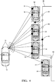
- Fig. 2 shows the vehicle 10 in an urban environment where parked vehicles 30 are present.
- the parked vehicles 30 are detected by the radar system 14 ( Fig. 1 ), i.e. radar detection points 16 originating from the parked vehicles 30 are created.
- the parked vehicles 30 are temporarily present objects and therefore not recorded in the navigation map.
- the radar system 14 may confuse the parked vehicles 30 with the building 38.
- the self-localization of the vehicle 10 is likely to fail.
- control and processing unit of the radar system 14 is configured to carry out an improved method for determining the position of the vehicle 10, as is described below.
- the radar detection points 16 are not only used for the Scan Matching process, but also for a discrimination between buildings 38 or other infrastructural elements, on the one hand, and parked vehicles 30 or other temporary objects, on the other hand.
- radar detection points 16 of successive radar scans are collected over a time period.
- Local detection features of the collected radar detection points 16 are used to create a feature map 40 as shown in Fig. 3 .
- the number and/or the signal amplitude of radar detection points 16 collected over the time period for a specific spot or region and/or derived quantities can be determined and handled as detection features.
- features derived from additional information like height information and/or polarization information can be determined as detection features.
- a detection feature is a property of a point or a region which provides local information about the type and/or the statistics of radar detections.
- the detection features are determined in relation to the coordinates of the corresponding radar detection points 16.
- a grid map comprising a regular two-dimensional arrangement of cells is created.
- the detection features are assigned to the cells of the grid map.
- a feature map 40 is created, preferably in fixed world coordinates.
- the exemplary feature map 40 according to Fig. 3 is an "occupancy map", i. e. the grey values correlate with the occupancy probabilities for the individual cells.
- the feature map can be a "free space map”. It has to be noted that the feature map 40 can be colour-coded. Also, the feature map 40 can have a plurality of feature layers, for example 5-10 feature layers.
- a classifier is applied to the feature map 40 to determine regions which are likely to be occupied by parked vehicles 30 or the like.
- a trainable grid-based classifier comprising a Deep Neural Network and/or a Support Vector Machine is used.
- the classifier is preferably trained off-line, for example by means of a set of training maps having manually marked regions that are occupied by parked vehicles or the like.
- radar detection points 16 which are located in a temporarily occupied region 56 are considered to a lesser extent than radar detection points 16 which are not located in a temporarily occupied region 56.
- radar detection points 16 which are located in a temporarily occupied region 56 are excluded from the matching.
- a weighted matching is performed and the weights of radar detection points 16 which are located in a temporarily occupied region 56 are reduced with respect to the weights of radar detection points 16 which are not located in a temporarily occupied region 56.
- each weight is determined according to the probability of the respective spot being located in a temporarily occupied region 56.
- the matching and the classification are carried out in parallel.
- the radar detection points 16 of successive radar scans are continuously collected and the feature map 40 is regularly updated.
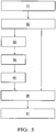
- Fig. 5 shows a flowchart illustrating a method for determining the position of the vehicle 10 ( Fig. 1 ) in accordance with an embodiment of the invention.
- a classifier based on a Deep Neural Network or a Support Vector Machine is trained to discriminate between temporarily occupied regions 56, free space regions and/or permanently occupied regions based on feature map 40.
- the classifier is applied to a set of feature maps 40 having manually marked regions.
- radar scans respectively comprising a plurality of radar detection points 16 are successively acquired.
- a feature map 40 ( Fig. 3 ) of the vicinity of the vehicle 10 is created or updated in a step 63.
- a subsequent step 64 the trained classifier is applied to the feature map 40.
- temporarily occupied regions 56 ( Fig. 4 ) which are likely to be occupied by parked vehicles 30 are determined in a step 65.
- a Scan Matching process using the radar detection points 16 and elements 24 ( Fig. 1 ) of a navigation map is carried out in a step 66. Radar detection points 16 which are located in a temporarily occupied region 56 are excluded from the matching or at least considered to a lesser extent than radar detection points 16 which are not located in a temporarily occupied region 56.
- the position of the vehicle 10 is determined in a step 67.
- Radar sensors are able to perceive objects like buildings 38 ( Fig. 2 ) despite the line of sight is occluded by parked vehicles 30. This ability is given by the radar reflections on the ground surface below the parked vehicle 30. Based on such ground reflections, additional radar detection points 60 are collected. Due to the classification according to an embodiment of the invention, such additional radar detection points 60 can be used as well to make the Scan Matching process even more robust.
- the invention increases the robustness, availability and quality of ego-vehicle localization, in particular within urban environments.
Landscapes
- Engineering & Computer Science (AREA)
- Remote Sensing (AREA)
- Radar, Positioning & Navigation (AREA)
- Physics & Mathematics (AREA)
- Computer Networks & Wireless Communication (AREA)
- General Physics & Mathematics (AREA)
- Electromagnetism (AREA)
- Radar Systems Or Details Thereof (AREA)
- Traffic Control Systems (AREA)
- Navigation (AREA)
Abstract
Description
- The invention relates to a method for determining the position of a vehicle equipped with a radar system, wherein the radar system includes at least one radar sensor adapted to receive radar signals emitted from at least one radar emitter of the radar system and reflected from an object in a vicinity of the vehicle towards the radar sensor, wherein the method comprises:
- (i) successively acquiring radar scans respectively comprising a plurality of radar detection points, wherein each radar detection point is evaluated from a radar signal received at the radar sensor and representing a location in the vicinity of the vehicle,
- (ii) determining, from a database, a predefined navigation map comprising at least one element representing a static landmark in the vicinity of the vehicle,
- (iii) matching at least a subset of the plurality of radar detection points of a radar scan and the at least one element of the navigation map, and
- (iv) determining the position of the vehicle based on the matching.
- The self-localization or ego-localization of a vehicle with respect to a predefined map such as a navigation map is an important task in the field of autonomous driving and similar applications. On-board radar systems are able to detect objects like buildings, trees, poles and other vehicles - even under bad weather conditions.
- The radar detections acquired by a radar system can be used to localize the vehicle within the navigation map. The navigation map can be gathered from a publicly available database. For example, it can be a so called "open-street map". Alternatively, the navigation map can be provided by a commercial map provider. Such maps usually are particularly accurate. Generally, the navigation map can be derived from a global database on the basis of a given position of the vehicle, e.g. from a global position system of the vehicle.
- The static landmarks can be known static objects, i. e. infrastructural objects or persistent objects, like walls of buildings, barriers, fences, pavement edges, poles, bigger plants, trees and the like. The map data stored in the database comprise simplified mathematical representations of the landmarks, for example in the form of extended geometrical objects like lines. Each of the elements comprises information about its position in a world coordinate system.
- The term "matching" in step (iii) can be understood in the sense of evaluating a correspondence between the radar detection points and the elements of the map. To carry out the matching, a so called Scan Matching algorithm can be applied. An example of a Scan Matching algorithm is disclosed in the European patent application number
18153439.7 - Although the methods described herein use a radar system of a vehicle, it is understood that the methods may also be adopted using detection points of a lidar system instead of a radar system. Combinations of radar and lidar detection points may also be possible.
- Scan Matching algorithms suffer from the problem that in real traffic spaces there are objects which are detectable by radar sensors, but are not recorded in the navigation map. Examples for such objects are parked vehicles. In particular in urban environments, such objects occur quite frequently. The Scan Matching algorithm may confuse the radar reflections from such objects with the elements of the navigation map. In such a case, the self-localization process usually fails. In particular, vehicles parked parallel to the road course line up similar to elongated infrastructural objects. This is problematic for the important lateral self-localization of a vehicle.
- It is an object of the invention to provide an improved method for determining the position of a vehicle, in particular a method which has an enhanced robustness and which is suitable for urban environments.
- The object is satisfied by a method in accordance with claim 1.
- According to the invention, radar detection points of successive scans are collected over a time period and a feature map of the vicinity of the vehicle is created, wherein the feature map comprises a plurality of detection features of the collected radar detection points, wherein a classifier is applied to the feature map to determine temporarily occupied regions which are likely to be occupied by temporarily present objects not recorded in the navigation map, and wherein in step (iii), radar detection points which are located in a temporarily occupied region are considered to a lesser extent than radar detection points which are not located in a temporarily occupied region.
- In other words, the radar detection points are accumulated over time and - parallel to the matching process - used to establish a local map containing information related to the presence of objects which are not recorded in the navigation map. This provides an additional semantic weighting of radar detection points. The additional information contained in the feature map is considered in the matching process. Thus, ambiguities between the radar measurements and the navigation map are avoided. The Scan Matching process is stable even if a plurality of parked vehicles is present in the vicinity of the vehicle. The invention therefore enables a particularly robust self-localization of vehicles within any kind of environment and in particular in urban environments.
- Advantageous embodiments of the invention are specified in the dependent claims, in the description and in the appended drawings.
- Preferably, the radar detection points of successive scans are continuously collected and the feature map is regularly updated. This can be done simultaneously to the matching process. The result of the classification is more reliable if any available measurements are exploited.
- In order to consider radar detection points which are located in a temporarily occupied region to a lesser extent than radar detection points which are not located in a temporarily occupied region, radar detection points which are located in a temporarily occupied region can simply be excluded from the matching.
- Alternatively, a weighted matching can be performed, wherein the weights of radar detection points which are located in a temporarily occupied region are reduced with respect to the weights of radar detection points which are not located in a temporarily occupied region. In particular, the weights can be selected according to the probability with which the respective region is a temporarily occupied region. This enables a particularly reliable Scan Matching process.
- According to an embodiment of the invention, the feature map comprises a grid-like structure comprising a two-dimensional or multi-dimensional arrangement of cells and the detection features are assigned to the cells. Thus, the detection features are localized via the cell positions. The cell pattern can be easily handled as an array by a computer program. The cell size preferably ranges from 1cm × 1cm to 50cm × 50cm. It is preferred that for each cell, at least two features and more preferably 4-20 features are determined. Preferably, the cells are non-overlapping.
- It is preferable that the feature map is created in fixed world coordinates. To achieve this, the coordinates of the radar detection points, typically given in a vehicle coordinate system, can be transformed to coordinates of a world coordinate system. If the feature map is created in fixed world coordinates, it can easily be related to the navigation map in order to define the temporarily occupied regions within the navigation map. In principle, the feature map can be created in any appropriate coordinate system, dependent on the respective application.
- According to a further embodiment of the invention, the classifier is a grid-based classifier. Grey scales or colours can represent values related to the detection features. In particular, the feature map can be created in the form of a multi-dimensional feature map.
- Preferably, the classifier is a trainable classifier. In particular, the classifier can be trained off-line, for example by means of a set of training maps having marked occupied areas.
- The classifier can comprise a Deep Neural Network and/or a Support Vector Machine. Such classifiers are specifically flexible and efficient. However, other types of classifiers may be used as well.
- According to another embodiment of the invention, regions of the feature map are classified into one of at least two predefined classes by means of the classifier, wherein the at least two predefined classes include a temporary object class and a non-temporary object class. The temporary object class can be a parked vehicle class which represents areas that are occupied by parked vehicles. The non-temporary object class can represent areas which are permanently occupied. According to a specific embodiment of the invention, cells of a grid-like feature map or of the navigation map are respectively classified either into a temporary object class or into a non-temporary object class.
- The classifier can estimate a class probability for a region, wherein the region can be classified as a temporarily occupied region if the class probability exceeds a threshold.
- To improve the reliability of the classification, the feature map can have a plurality of feature layers which are derived from the detection features, in particular 4-20 feature layers.
- The determined detection features can include the number and/or the signal amplitude of radar detection points collected over the time period. Such detection features can be respectively determined for a specific location, e. g. for a cell of a grid-like structure.
- The determined detection features can include features derived from additional information like height information and/or polarization information. Radar systems often provide such additional information, which may be used to further enhance the robustness of the localization process.
- According to another embodiment of the invention, occupancy probabilities and/or free space probabilities for individual regions of the feature map are determined based on the detection features. In particular, the feature map can be created in the form of an "occupancy map" or a "free space map".
- The invention also relates to a vehicle equipped with a radar system, wherein the radar system includes at least one radar sensor adapted to receive radar signals emitted from at least one radar emitter of the radar system and reflected in a vicinity of the vehicle towards the radar sensor, and a control and processing unit connected to the radar sensor, wherein the control and processing unit is configured to carry out a method as specified in the present disclosure.
- The control and processing unit may comprise a storage device in which instructions implementing embodiments of the described methods are stored. Preferably, the method can be carried out without a mobile connection to a central server or the like. Therefore, the storage device can also comprise a database including data for determining a navigation map representing the vicinity of the vehicle. However, as the skilled person understands, use of a mobile connection can be made for updating or incorporating data while carrying out the method.
- The invention is described further in the following by means of exemplary embodiments shown in the drawings in which
- Fig. 1
- is an arrangement of schematic illustrations of a vehicle, a plurality of radar detection points and elements of a navigation map in a vehicle coordinate system;
- Fig. 2
- shows a vehicle in an environment, wherein the environment comprises parked vehicles and a building;
- Fig. 3
- shows a feature map created in the context of a method according to the invention along with a host vehicle;
- Fig. 4
- shows the arrangement according to
Fig. 2 , wherein temporarily occupied regions determined in the context of a method according to the invention are marked; and - Fig. 5
- is a schematic overview illustrating a method according to the invention for determining the position of a vehicle.
- In the figures, the same or corresponding elements are indicated with the same reference signs.
-
Fig. 1 provides a basic illustration of a so called Scan Matching procedure used for the self-localization of avehicle 10. In the three parts ofFig. 1 , thevehicle 10 is respectively shown in a Cartesian world coordinatesystem 12 having axes x and y. Thevehicle 10 has aradar system 14 comprising a total of four pairs of radar sensors and radar emitters, which are positioned in each of the corners of thevehicle 10. Therefore, theradar system 14 is configured to monitor an angle range of 360 degrees around the vicinity of thevehicle 10. It is understood that thevehicle 10 can have a different number of radar sensors and emitters which also can be positioned in a different configuration than shown inFig. 1 . Theradar system 14 comprises an electronic control and processing unit connected to the pairs of radar sensors and radar emitters. The electronic control and processing unit is not shown inFig. 1 . - The radar system is configured to successively perform radar scans in a known manner for acquiring radar detection points 16, i.e. positions of surface spots of objects present in the vicinity of the
vehicle 10. - In the left part of
Fig. 1 , exemplary radar detection points 16 are shown. In the central part ofFig. 1 ,elements 24 representing static landmarks in the vicinity of thevehicle 10 are shown in addition to the radar detection points 16. In particular, theelements 24 can represent walls of buildings or groups of walls. It is understood that theelements 24 may form a predefined navigation map with regard to thevehicle 10 and that theelements 24 are computer-implemented representations of real static landmarks. Theelements 24 can be gathered from a database by the control and processing unit of the radar system. - According to the central part of
Fig. 1 , theelements 24 show a geometrical correspondence with the arrangement of the detection points 16. However, there is an angular displacement between theelements 24 and the detection points 16. This displacement can be compensated by a Scan Matching procedure. Such a procedure comprises finding a transformation function which can be used to correct the inaccurate position, for example a rigid transformation function including a translation and a rotation. In particular, a matching as disclosed in the European patent application number18153439.7 Fig. 1 , in which the inaccurate position of thevehicle 10 from the central part ofFig. 1 has been corrected. While the left part ofFig. 1 shows the detection points 16 without the navigation map, both the central part and the right part ofFig. 1 show overlays of detection points 16 and the navigation map. In the right part ofFig. 1 , the detection points 16 have been matched and the position of thevehicle 10 has been corrected correspondingly. The corrected position of thevehicle 10 within the world coordinatesystem 12 can be used for different applications such as autonomous driving. The determining of the position of thevehicle 10 within the navigation map is called self-localization or ego-localization. -
Fig. 2 shows thevehicle 10 in an urban environment where parkedvehicles 30 are present. The parkedvehicles 30 are detected by the radar system 14 (Fig. 1 ), i.e. radar detection points 16 originating from the parkedvehicles 30 are created. The parkedvehicles 30 are temporarily present objects and therefore not recorded in the navigation map. However, since the parkedvehicles 30 line up near the wall of abuilding 38, which is recorded in the navigation map, theradar system 14 may confuse the parkedvehicles 30 with thebuilding 38. As a consequence of the contradicting map information, the self-localization of thevehicle 10 is likely to fail. - In order to avoid such a failure, the control and processing unit of the
radar system 14 is configured to carry out an improved method for determining the position of thevehicle 10, as is described below. - According to an embodiment of the invention, the radar detection points 16 are not only used for the Scan Matching process, but also for a discrimination between
buildings 38 or other infrastructural elements, on the one hand, and parkedvehicles 30 or other temporary objects, on the other hand. In particular, radar detection points 16 of successive radar scans are collected over a time period. Local detection features of the collected radar detection points 16 are used to create afeature map 40 as shown inFig. 3 . In particular, the number and/or the signal amplitude of radar detection points 16 collected over the time period for a specific spot or region and/or derived quantities can be determined and handled as detection features. Alternatively or additionally, features derived from additional information like height information and/or polarization information can be determined as detection features. - In the context of the present disclosure, a detection feature is a property of a point or a region which provides local information about the type and/or the statistics of radar detections. The detection features are determined in relation to the coordinates of the corresponding radar detection points 16. Preferably, a grid map comprising a regular two-dimensional arrangement of cells is created. The detection features are assigned to the cells of the grid map. Thus, a
feature map 40 is created, preferably in fixed world coordinates. - The
exemplary feature map 40 according toFig. 3 is an "occupancy map", i. e. the grey values correlate with the occupancy probabilities for the individual cells. Alternatively, the feature map can be a "free space map". It has to be noted that thefeature map 40 can be colour-coded. Also, thefeature map 40 can have a plurality of feature layers, for example 5-10 feature layers. - In the
feature map 40, regions occupied by parkedvehicles 30 are clearly discernible. In accordance with an embodiment of the invention, a classifier is applied to thefeature map 40 to determine regions which are likely to be occupied by parkedvehicles 30 or the like. Preferably, a trainable grid-based classifier comprising a Deep Neural Network and/or a Support Vector Machine is used. The classifier is preferably trained off-line, for example by means of a set of training maps having manually marked regions that are occupied by parked vehicles or the like. - Based on the classification result, those regions having a predefined probability of being occupied by parked
vehicles 30 or the like, for example a probability of 90%, are defined as temporarilyoccupied regions 56 as shown inFig. 4 . In the Scan Matching process (Fig. 1 ), radar detection points 16 which are located in a temporarily occupied region 56 (Fig. 4 ) are considered to a lesser extent than radar detection points 16 which are not located in a temporarily occupiedregion 56. - According to an embodiment of the invention, radar detection points 16 which are located in a temporarily occupied
region 56 are excluded from the matching. According to another embodiment of the invention, a weighted matching is performed and the weights of radar detection points 16 which are located in a temporarily occupiedregion 56 are reduced with respect to the weights of radar detection points 16 which are not located in a temporarily occupiedregion 56. According to a specific embodiment of the invention, each weight is determined according to the probability of the respective spot being located in a temporarily occupiedregion 56. - The matching and the classification are carried out in parallel. Preferably, the radar detection points 16 of successive radar scans are continuously collected and the
feature map 40 is regularly updated. -
Fig. 5 shows a flowchart illustrating a method for determining the position of the vehicle 10 (Fig. 1 ) in accordance with an embodiment of the invention. In astep 61, a classifier based on a Deep Neural Network or a Support Vector Machine is trained to discriminate between temporarilyoccupied regions 56, free space regions and/or permanently occupied regions based onfeature map 40. For the training, the classifier is applied to a set of feature maps 40 having manually marked regions. In astep 62, radar scans respectively comprising a plurality of radar detection points 16 are successively acquired. A feature map 40 (Fig. 3 ) of the vicinity of thevehicle 10 is created or updated in astep 63. In asubsequent step 64, the trained classifier is applied to thefeature map 40. Based on the classification result, temporarily occupied regions 56 (Fig. 4 ) which are likely to be occupied by parkedvehicles 30 are determined in astep 65. A Scan Matching process using the radar detection points 16 and elements 24 (Fig. 1 ) of a navigation map is carried out in astep 66. Radar detection points 16 which are located in a temporarily occupiedregion 56 are excluded from the matching or at least considered to a lesser extent than radar detection points 16 which are not located in a temporarily occupiedregion 56. Based on the matching ofstep 66, the position of thevehicle 10 is determined in astep 67. - Radar sensors are able to perceive objects like buildings 38 (
Fig. 2 ) despite the line of sight is occluded by parkedvehicles 30. This ability is given by the radar reflections on the ground surface below the parkedvehicle 30. Based on such ground reflections, additional radar detection points 60 are collected. Due to the classification according to an embodiment of the invention, such additional radar detection points 60 can be used as well to make the Scan Matching process even more robust. - Therefore, the invention increases the robustness, availability and quality of ego-vehicle localization, in particular within urban environments.
-
- 10
- vehicle
- 12
- world coordinate system
- 14
- radar system
- 16
- detection point
- 24
- element of navigation map
- 30
- parked vehicle
- 38
- building
- 40
- feature map
- 56
- temporarily occupied region
- 60
- ground reflection detection point
- 61-67
- method steps
Claims (14)
- A method for determining the position of a vehicle (10) equipped with a radar system (14), wherein the radar system includes at least one radar sensor adapted to receive radar signals emitted from at least one radar emitter of the radar system and reflected from an object in a vicinity of the vehicle (10) towards the radar sensor,
wherein the method comprises:(i) successively acquiring (62) radar scans respectively comprising a plurality of radar detection points (16, 60), wherein each radar detection point (16, 60) is evaluated from a radar signal received at the radar sensor and representing a location in the vicinity of the vehicle (10),(ii) determining, from a database, a predefined navigation map comprising at least one element (24) representing a static landmark in the vicinity of the vehicle (10),(iii) matching (66) at least a subset of the plurality of radar detection points (16, 60) of a radar scan and the at least one element (24) of the navigation map, and(iv) determining (67) the position of the vehicle (10) based on the matching,wherein radar detection points (16, 60) of successive scans are collected over a time period and a feature map (40) of the vicinity of the vehicle (10) is created (63), wherein the feature map (40) comprises a plurality of detection features of the collected radar detection points (16, 60),
wherein a classifier is applied to the feature map (40) to determine temporarily occupied regions (56) which are likely to be occupied by temporarily present objects (30) not recorded in the navigation map, and
wherein in step (iii), radar detection points (16, 60) which are located in a temporarily occupied region (56) are considered to a lesser extent than radar detection points (16, 60) which are not located in a temporarily occupied region (56). - The method according to claim 1,
wherein the radar detection points (16, 60) of successive scans are continuously collected and the feature map (40) is regularly updated. - The method according to claim 1 or 2,
wherein in step (iii), radar detection points (16, 60) which are located in a temporarily occupied region (56) are excluded from the matching. - The method according to claim 1 or 2,
wherein in step (iii), a weighted matching is performed and the weights of radar detection points (16, 60) which are located in a temporarily occupied region (56) are reduced with respect to the weights of radar detection points (16, 60) which are not located in a temporarily occupied region (56). - The method according to at least one of the preceding claims,
wherein the feature map (40) comprises a grid-like structure comprising a two-dimensional or multi-dimensional arrangement of cells and the detection features are assigned to the cells. - The method according to at least one of the preceding claims,
wherein the classifier is a grid-based classifier. - The method according to at least one of the preceding claims,
wherein the classifier is a trainable classifier. - The method according to claim 7,
wherein the classifier comprises a Deep Neural Network and/or a Support Vector Machine. - The method according to at least one of the preceding claims,
wherein regions of the feature map (40) are classified into one of at least two predefined classes by means of the classifier, wherein the at least two predefined classes include a temporary object class and a non-temporary object class. - The method according to at least one of the preceding claims,
wherein the feature map (40) has a plurality of feature layers which are derived from the detection features, in particular 4-20 feature layers. - The method according to at least one of the preceding claims,
wherein the determined detection features include the number and/or the signal amplitude of radar detection points (16, 60) collected over the time period. - The method according to at least one of the preceding claims,
wherein the determined detection features include features derived from additional information like height information and/or polarization information. - The method according to at least one of the preceding claims,
wherein occupancy probabilities and/or free space probabilities for individual regions of the feature map (40) are determined based on the detection features. - A vehicle (10) equipped with a radar system (14), wherein the radar system includes at least one radar sensor adapted to receive radar signals emitted from at least one radar emitter of the radar system and reflected in a vicinity of the vehicle (10) towards the radar sensor, and a control and processing unit connected to the radar sensor, wherein the control and processing unit is configured to carry out a method according to at least one of the preceding claims.
Priority Applications (1)
| Application Number | Priority Date | Filing Date | Title |
|---|---|---|---|
| EP18193143.7A EP3620811B1 (en) | 2018-09-07 | 2018-09-07 | Method for determining the position of a vehicle |
Applications Claiming Priority (1)
| Application Number | Priority Date | Filing Date | Title |
|---|---|---|---|
| EP18193143.7A EP3620811B1 (en) | 2018-09-07 | 2018-09-07 | Method for determining the position of a vehicle |
Publications (2)
| Publication Number | Publication Date |
|---|---|
| EP3620811A1 true EP3620811A1 (en) | 2020-03-11 |
| EP3620811B1 EP3620811B1 (en) | 2022-06-22 |
Family
ID=63528582
Family Applications (1)
| Application Number | Title | Priority Date | Filing Date |
|---|---|---|---|
| EP18193143.7A Active EP3620811B1 (en) | 2018-09-07 | 2018-09-07 | Method for determining the position of a vehicle |
Country Status (1)
| Country | Link |
|---|---|
| EP (1) | EP3620811B1 (en) |
Cited By (7)
| Publication number | Priority date | Publication date | Assignee | Title |
|---|---|---|---|---|
| CN111949943A (en) * | 2020-07-24 | 2020-11-17 | 北京航空航天大学 | A Vehicle Fusion Localization Method for V2X and Laser Point Cloud Registration for Advanced Autonomous Driving |
| CN112255616A (en) * | 2020-10-19 | 2021-01-22 | 三一机器人科技有限公司 | Multi-radar reflecting column positioning method and reflecting column positioning device |
| CN113284342A (en) * | 2021-05-17 | 2021-08-20 | 上海欧菲智能车联科技有限公司 | Empty parking space detection method and device, vehicle and computer equipment |
| CN115825947A (en) * | 2022-12-28 | 2023-03-21 | 广东嘉腾机器人自动化有限公司 | AGV positioning navigation method |
| WO2023060403A1 (en) * | 2021-10-11 | 2023-04-20 | Abb Schweiz Ag | Method and electronic device for controlling robotic system |
| GB2621325A (en) * | 2022-08-04 | 2024-02-14 | Continental Autonomous Mobility Germany GmbH | Method and system for generating a map and the localization of an ego-vehicle |
| CN121385825A (en) * | 2025-12-24 | 2026-01-23 | 国营洛阳丹城无线电厂 | Detection platform and detection method of radar equipment precise follow-up system |
Citations (2)
| Publication number | Priority date | Publication date | Assignee | Title |
|---|---|---|---|---|
| US20160139255A1 (en) * | 2014-11-17 | 2016-05-19 | Volkswagen Aktiengesellschaft | Method and device for the localization of a vehicle from a fixed reference map |
| US20180149739A1 (en) * | 2015-06-01 | 2018-05-31 | Robert Bosch Gmbh | Method and device for determining the position of a vehicle |
-
2018
- 2018-09-07 EP EP18193143.7A patent/EP3620811B1/en active Active
Patent Citations (2)
| Publication number | Priority date | Publication date | Assignee | Title |
|---|---|---|---|---|
| US20160139255A1 (en) * | 2014-11-17 | 2016-05-19 | Volkswagen Aktiengesellschaft | Method and device for the localization of a vehicle from a fixed reference map |
| US20180149739A1 (en) * | 2015-06-01 | 2018-05-31 | Robert Bosch Gmbh | Method and device for determining the position of a vehicle |
Cited By (9)
| Publication number | Priority date | Publication date | Assignee | Title |
|---|---|---|---|---|
| CN111949943A (en) * | 2020-07-24 | 2020-11-17 | 北京航空航天大学 | A Vehicle Fusion Localization Method for V2X and Laser Point Cloud Registration for Advanced Autonomous Driving |
| CN112255616A (en) * | 2020-10-19 | 2021-01-22 | 三一机器人科技有限公司 | Multi-radar reflecting column positioning method and reflecting column positioning device |
| CN112255616B (en) * | 2020-10-19 | 2024-04-23 | 三一机器人科技有限公司 | Multi-radar reflective column positioning method and reflective column positioning device |
| CN113284342A (en) * | 2021-05-17 | 2021-08-20 | 上海欧菲智能车联科技有限公司 | Empty parking space detection method and device, vehicle and computer equipment |
| CN113284342B (en) * | 2021-05-17 | 2022-09-06 | 上海欧菲智能车联科技有限公司 | Empty parking space detection method and device, vehicle and computer equipment |
| WO2023060403A1 (en) * | 2021-10-11 | 2023-04-20 | Abb Schweiz Ag | Method and electronic device for controlling robotic system |
| GB2621325A (en) * | 2022-08-04 | 2024-02-14 | Continental Autonomous Mobility Germany GmbH | Method and system for generating a map and the localization of an ego-vehicle |
| CN115825947A (en) * | 2022-12-28 | 2023-03-21 | 广东嘉腾机器人自动化有限公司 | AGV positioning navigation method |
| CN121385825A (en) * | 2025-12-24 | 2026-01-23 | 国营洛阳丹城无线电厂 | Detection platform and detection method of radar equipment precise follow-up system |
Also Published As
| Publication number | Publication date |
|---|---|
| EP3620811B1 (en) | 2022-06-22 |
Similar Documents
| Publication | Publication Date | Title |
|---|---|---|
| EP3620811B1 (en) | Method for determining the position of a vehicle | |
| EP3517996B1 (en) | Method for determining the position of a vehicle | |
| JP6166294B2 (en) | Automatic driving system, automatic driving method and computing device | |
| Jeong et al. | Road-SLAM: Road marking based SLAM with lane-level accuracy | |
| US8558679B2 (en) | Method of analyzing the surroundings of a vehicle | |
| CN113189975B (en) | Method for determining position data and/or movement data of a vehicle | |
| US20090228204A1 (en) | System and method for map matching with sensor detected objects | |
| EP2052208B1 (en) | Determining the location of a vehicle on a map | |
| CN108363065A (en) | Object detecting system | |
| CN112781599B (en) | Method for determining the position of a vehicle | |
| US20200256977A1 (en) | Method and system for mapping and locating a vehicle based on radar measurements | |
| JP7329079B2 (en) | How to generate universally usable feature maps | |
| US20220229153A1 (en) | Abnormality diagnosis system | |
| WO2021051071A1 (en) | Improved navigation and localization using surface-penetrating radar and deep learning | |
| JP6263453B2 (en) | Momentum estimation device and program | |
| Ahn et al. | A particle filter localization method using 2D laser sensor measurements and road features for autonomous vehicle | |
| Li et al. | Environment mapping and vehicle localization with a high-resolution radar prototype | |
| EP4737854A1 (en) | Methods, systems, and computer program products for georeferencing | |
| RU2784310C1 (en) | Method for mapping of area for autonomous vehicles | |
| CN112050830A (en) | Motion state estimation method and device | |
| EP3696507B1 (en) | Representing an environment by cylindrical and planar structures | |
| Jiang | Semi-automated Generation of Road Transition Lines Using Mobile Laser Scanning Data | |
| Ciocarlie | Obstacle avoidance and path planning using a sparse array of sonars | |
| Andersen et al. | Visual navigation for mobile robots |
Legal Events
| Date | Code | Title | Description |
|---|---|---|---|
| PUAI | Public reference made under article 153(3) epc to a published international application that has entered the european phase |
Free format text: ORIGINAL CODE: 0009012 |
|
| STAA | Information on the status of an ep patent application or granted ep patent |
Free format text: STATUS: THE APPLICATION HAS BEEN PUBLISHED |
|
| AK | Designated contracting states |
Kind code of ref document: A1 Designated state(s): AL AT BE BG CH CY CZ DE DK EE ES FI FR GB GR HR HU IE IS IT LI LT LU LV MC MK MT NL NO PL PT RO RS SE SI SK SM TR |
|
| AX | Request for extension of the european patent |
Extension state: BA ME |
|
| STAA | Information on the status of an ep patent application or granted ep patent |
Free format text: STATUS: REQUEST FOR EXAMINATION WAS MADE |
|
| 17P | Request for examination filed |
Effective date: 20200901 |
|
| RBV | Designated contracting states (corrected) |
Designated state(s): AL AT BE BG CH CY CZ DE DK EE ES FI FR GB GR HR HU IE IS IT LI LT LU LV MC MK MT NL NO PL PT RO RS SE SI SK SM TR |
|
| GRAP | Despatch of communication of intention to grant a patent |
Free format text: ORIGINAL CODE: EPIDOSNIGR1 |
|
| STAA | Information on the status of an ep patent application or granted ep patent |
Free format text: STATUS: GRANT OF PATENT IS INTENDED |
|
| INTG | Intention to grant announced |
Effective date: 20220105 |
|
| GRAS | Grant fee paid |
Free format text: ORIGINAL CODE: EPIDOSNIGR3 |
|
| GRAA | (expected) grant |
Free format text: ORIGINAL CODE: 0009210 |
|
| STAA | Information on the status of an ep patent application or granted ep patent |
Free format text: STATUS: THE PATENT HAS BEEN GRANTED |
|
| AK | Designated contracting states |
Kind code of ref document: B1 Designated state(s): AL AT BE BG CH CY CZ DE DK EE ES FI FR GB GR HR HU IE IS IT LI LT LU LV MC MK MT NL NO PL PT RO RS SE SI SK SM TR |
|
| REG | Reference to a national code |
Ref country code: GB Ref legal event code: FG4D |
|
| REG | Reference to a national code |
Ref country code: CH Ref legal event code: EP |
|
| REG | Reference to a national code |
Ref country code: DE Ref legal event code: R096 Ref document number: 602018036942 Country of ref document: DE |
|
| REG | Reference to a national code |
Ref country code: AT Ref legal event code: REF Ref document number: 1500107 Country of ref document: AT Kind code of ref document: T Effective date: 20220715 |
|
| REG | Reference to a national code |
Ref country code: IE Ref legal event code: FG4D |
|
| REG | Reference to a national code |
Ref country code: LT Ref legal event code: MG9D |
|
| REG | Reference to a national code |
Ref country code: NL Ref legal event code: MP Effective date: 20220622 |
|
| PG25 | Lapsed in a contracting state [announced via postgrant information from national office to epo] |
Ref country code: SE Free format text: LAPSE BECAUSE OF FAILURE TO SUBMIT A TRANSLATION OF THE DESCRIPTION OR TO PAY THE FEE WITHIN THE PRESCRIBED TIME-LIMIT Effective date: 20220622 Ref country code: NO Free format text: LAPSE BECAUSE OF FAILURE TO SUBMIT A TRANSLATION OF THE DESCRIPTION OR TO PAY THE FEE WITHIN THE PRESCRIBED TIME-LIMIT Effective date: 20220922 Ref country code: LT Free format text: LAPSE BECAUSE OF FAILURE TO SUBMIT A TRANSLATION OF THE DESCRIPTION OR TO PAY THE FEE WITHIN THE PRESCRIBED TIME-LIMIT Effective date: 20220622 Ref country code: HR Free format text: LAPSE BECAUSE OF FAILURE TO SUBMIT A TRANSLATION OF THE DESCRIPTION OR TO PAY THE FEE WITHIN THE PRESCRIBED TIME-LIMIT Effective date: 20220622 Ref country code: GR Free format text: LAPSE BECAUSE OF FAILURE TO SUBMIT A TRANSLATION OF THE DESCRIPTION OR TO PAY THE FEE WITHIN THE PRESCRIBED TIME-LIMIT Effective date: 20220923 Ref country code: FI Free format text: LAPSE BECAUSE OF FAILURE TO SUBMIT A TRANSLATION OF THE DESCRIPTION OR TO PAY THE FEE WITHIN THE PRESCRIBED TIME-LIMIT Effective date: 20220622 Ref country code: BG Free format text: LAPSE BECAUSE OF FAILURE TO SUBMIT A TRANSLATION OF THE DESCRIPTION OR TO PAY THE FEE WITHIN THE PRESCRIBED TIME-LIMIT Effective date: 20220922 |
|
| REG | Reference to a national code |
Ref country code: AT Ref legal event code: MK05 Ref document number: 1500107 Country of ref document: AT Kind code of ref document: T Effective date: 20220622 |
|
| PG25 | Lapsed in a contracting state [announced via postgrant information from national office to epo] |
Ref country code: RS Free format text: LAPSE BECAUSE OF FAILURE TO SUBMIT A TRANSLATION OF THE DESCRIPTION OR TO PAY THE FEE WITHIN THE PRESCRIBED TIME-LIMIT Effective date: 20220622 Ref country code: LV Free format text: LAPSE BECAUSE OF FAILURE TO SUBMIT A TRANSLATION OF THE DESCRIPTION OR TO PAY THE FEE WITHIN THE PRESCRIBED TIME-LIMIT Effective date: 20220622 |
|
| PG25 | Lapsed in a contracting state [announced via postgrant information from national office to epo] |
Ref country code: NL Free format text: LAPSE BECAUSE OF FAILURE TO SUBMIT A TRANSLATION OF THE DESCRIPTION OR TO PAY THE FEE WITHIN THE PRESCRIBED TIME-LIMIT Effective date: 20220622 |
|
| PG25 | Lapsed in a contracting state [announced via postgrant information from national office to epo] |
Ref country code: SM Free format text: LAPSE BECAUSE OF FAILURE TO SUBMIT A TRANSLATION OF THE DESCRIPTION OR TO PAY THE FEE WITHIN THE PRESCRIBED TIME-LIMIT Effective date: 20220622 Ref country code: SK Free format text: LAPSE BECAUSE OF FAILURE TO SUBMIT A TRANSLATION OF THE DESCRIPTION OR TO PAY THE FEE WITHIN THE PRESCRIBED TIME-LIMIT Effective date: 20220622 Ref country code: RO Free format text: LAPSE BECAUSE OF FAILURE TO SUBMIT A TRANSLATION OF THE DESCRIPTION OR TO PAY THE FEE WITHIN THE PRESCRIBED TIME-LIMIT Effective date: 20220622 Ref country code: PT Free format text: LAPSE BECAUSE OF FAILURE TO SUBMIT A TRANSLATION OF THE DESCRIPTION OR TO PAY THE FEE WITHIN THE PRESCRIBED TIME-LIMIT Effective date: 20221024 Ref country code: ES Free format text: LAPSE BECAUSE OF FAILURE TO SUBMIT A TRANSLATION OF THE DESCRIPTION OR TO PAY THE FEE WITHIN THE PRESCRIBED TIME-LIMIT Effective date: 20220622 Ref country code: EE Free format text: LAPSE BECAUSE OF FAILURE TO SUBMIT A TRANSLATION OF THE DESCRIPTION OR TO PAY THE FEE WITHIN THE PRESCRIBED TIME-LIMIT Effective date: 20220622 Ref country code: CZ Free format text: LAPSE BECAUSE OF FAILURE TO SUBMIT A TRANSLATION OF THE DESCRIPTION OR TO PAY THE FEE WITHIN THE PRESCRIBED TIME-LIMIT Effective date: 20220622 Ref country code: AT Free format text: LAPSE BECAUSE OF FAILURE TO SUBMIT A TRANSLATION OF THE DESCRIPTION OR TO PAY THE FEE WITHIN THE PRESCRIBED TIME-LIMIT Effective date: 20220622 |
|
| PG25 | Lapsed in a contracting state [announced via postgrant information from national office to epo] |
Ref country code: PL Free format text: LAPSE BECAUSE OF FAILURE TO SUBMIT A TRANSLATION OF THE DESCRIPTION OR TO PAY THE FEE WITHIN THE PRESCRIBED TIME-LIMIT Effective date: 20220622 Ref country code: IS Free format text: LAPSE BECAUSE OF FAILURE TO SUBMIT A TRANSLATION OF THE DESCRIPTION OR TO PAY THE FEE WITHIN THE PRESCRIBED TIME-LIMIT Effective date: 20221022 |
|
| REG | Reference to a national code |
Ref country code: DE Ref legal event code: R097 Ref document number: 602018036942 Country of ref document: DE |
|
| RAP4 | Party data changed (patent owner data changed or rights of a patent transferred) |
Owner name: APTIV TECHNOLOGIES LIMITED |
|
| PG25 | Lapsed in a contracting state [announced via postgrant information from national office to epo] |
Ref country code: AL Free format text: LAPSE BECAUSE OF FAILURE TO SUBMIT A TRANSLATION OF THE DESCRIPTION OR TO PAY THE FEE WITHIN THE PRESCRIBED TIME-LIMIT Effective date: 20220622 |
|
| PG25 | Lapsed in a contracting state [announced via postgrant information from national office to epo] |
Ref country code: MC Free format text: LAPSE BECAUSE OF FAILURE TO SUBMIT A TRANSLATION OF THE DESCRIPTION OR TO PAY THE FEE WITHIN THE PRESCRIBED TIME-LIMIT Effective date: 20220622 Ref country code: DK Free format text: LAPSE BECAUSE OF FAILURE TO SUBMIT A TRANSLATION OF THE DESCRIPTION OR TO PAY THE FEE WITHIN THE PRESCRIBED TIME-LIMIT Effective date: 20220622 |
|
| PLBE | No opposition filed within time limit |
Free format text: ORIGINAL CODE: 0009261 |
|
| REG | Reference to a national code |
Ref country code: CH Ref legal event code: PL |
|
| STAA | Information on the status of an ep patent application or granted ep patent |
Free format text: STATUS: NO OPPOSITION FILED WITHIN TIME LIMIT |
|
| REG | Reference to a national code |
Ref country code: BE Ref legal event code: MM Effective date: 20220930 |
|
| 26N | No opposition filed |
Effective date: 20230323 |
|
| P01 | Opt-out of the competence of the unified patent court (upc) registered |
Effective date: 20230420 |
|
| PG25 | Lapsed in a contracting state [announced via postgrant information from national office to epo] |
Ref country code: LU Free format text: LAPSE BECAUSE OF NON-PAYMENT OF DUE FEES Effective date: 20220907 |
|
| PG25 | Lapsed in a contracting state [announced via postgrant information from national office to epo] |
Ref country code: LI Free format text: LAPSE BECAUSE OF NON-PAYMENT OF DUE FEES Effective date: 20220930 Ref country code: IE Free format text: LAPSE BECAUSE OF NON-PAYMENT OF DUE FEES Effective date: 20220907 Ref country code: CH Free format text: LAPSE BECAUSE OF NON-PAYMENT OF DUE FEES Effective date: 20220930 |
|
| PG25 | Lapsed in a contracting state [announced via postgrant information from national office to epo] |
Ref country code: SI Free format text: LAPSE BECAUSE OF FAILURE TO SUBMIT A TRANSLATION OF THE DESCRIPTION OR TO PAY THE FEE WITHIN THE PRESCRIBED TIME-LIMIT Effective date: 20220622 |
|
| PG25 | Lapsed in a contracting state [announced via postgrant information from national office to epo] |
Ref country code: BE Free format text: LAPSE BECAUSE OF NON-PAYMENT OF DUE FEES Effective date: 20220930 |
|
| PG25 | Lapsed in a contracting state [announced via postgrant information from national office to epo] |
Ref country code: IT Free format text: LAPSE BECAUSE OF FAILURE TO SUBMIT A TRANSLATION OF THE DESCRIPTION OR TO PAY THE FEE WITHIN THE PRESCRIBED TIME-LIMIT Effective date: 20220622 |
|
| PG25 | Lapsed in a contracting state [announced via postgrant information from national office to epo] |
Ref country code: HU Free format text: LAPSE BECAUSE OF FAILURE TO SUBMIT A TRANSLATION OF THE DESCRIPTION OR TO PAY THE FEE WITHIN THE PRESCRIBED TIME-LIMIT; INVALID AB INITIO Effective date: 20180907 |
|
| PG25 | Lapsed in a contracting state [announced via postgrant information from national office to epo] |
Ref country code: CY Free format text: LAPSE BECAUSE OF FAILURE TO SUBMIT A TRANSLATION OF THE DESCRIPTION OR TO PAY THE FEE WITHIN THE PRESCRIBED TIME-LIMIT Effective date: 20220622 |
|
| PG25 | Lapsed in a contracting state [announced via postgrant information from national office to epo] |
Ref country code: MK Free format text: LAPSE BECAUSE OF FAILURE TO SUBMIT A TRANSLATION OF THE DESCRIPTION OR TO PAY THE FEE WITHIN THE PRESCRIBED TIME-LIMIT Effective date: 20220622 |
|
| PG25 | Lapsed in a contracting state [announced via postgrant information from national office to epo] |
Ref country code: TR Free format text: LAPSE BECAUSE OF FAILURE TO SUBMIT A TRANSLATION OF THE DESCRIPTION OR TO PAY THE FEE WITHIN THE PRESCRIBED TIME-LIMIT Effective date: 20220622 |
|
| PG25 | Lapsed in a contracting state [announced via postgrant information from national office to epo] |
Ref country code: MT Free format text: LAPSE BECAUSE OF FAILURE TO SUBMIT A TRANSLATION OF THE DESCRIPTION OR TO PAY THE FEE WITHIN THE PRESCRIBED TIME-LIMIT Effective date: 20220622 |
|
| PG25 | Lapsed in a contracting state [announced via postgrant information from national office to epo] |
Ref country code: BG Free format text: LAPSE BECAUSE OF FAILURE TO SUBMIT A TRANSLATION OF THE DESCRIPTION OR TO PAY THE FEE WITHIN THE PRESCRIBED TIME-LIMIT Effective date: 20220622 |
|
| PG25 | Lapsed in a contracting state [announced via postgrant information from national office to epo] |
Ref country code: BG Free format text: LAPSE BECAUSE OF FAILURE TO SUBMIT A TRANSLATION OF THE DESCRIPTION OR TO PAY THE FEE WITHIN THE PRESCRIBED TIME-LIMIT Effective date: 20220622 |
|
| REG | Reference to a national code |
Ref country code: DE Ref legal event code: R081 Ref document number: 602018036942 Country of ref document: DE Owner name: APTIV TECHNOLOGIES AG, CH Free format text: FORMER OWNER: APTIV TECHNOLOGIES LIMITED, ST. MICHAEL, BB |
|
| PGFP | Annual fee paid to national office [announced via postgrant information from national office to epo] |
Ref country code: DE Payment date: 20250814 Year of fee payment: 8 |
|
| PGFP | Annual fee paid to national office [announced via postgrant information from national office to epo] |
Ref country code: GB Payment date: 20250818 Year of fee payment: 8 |
|
| PGFP | Annual fee paid to national office [announced via postgrant information from national office to epo] |
Ref country code: FR Payment date: 20250812 Year of fee payment: 8 |