EP3620707A1 - Wall mount and smart home system with such a smart wall mount - Google Patents
Wall mount and smart home system with such a smart wall mount Download PDFInfo
- Publication number
- EP3620707A1 EP3620707A1 EP18192882.1A EP18192882A EP3620707A1 EP 3620707 A1 EP3620707 A1 EP 3620707A1 EP 18192882 A EP18192882 A EP 18192882A EP 3620707 A1 EP3620707 A1 EP 3620707A1
- Authority
- EP
- European Patent Office
- Prior art keywords
- holding element
- wall mount
- wall
- positioning means
- data
- Prior art date
- Legal status (The legal status is an assumption and is not a legal conclusion. Google has not performed a legal analysis and makes no representation as to the accuracy of the status listed.)
- Granted
Links
Images



Classifications
-
- F—MECHANICAL ENGINEERING; LIGHTING; HEATING; WEAPONS; BLASTING
- F16—ENGINEERING ELEMENTS AND UNITS; GENERAL MEASURES FOR PRODUCING AND MAINTAINING EFFECTIVE FUNCTIONING OF MACHINES OR INSTALLATIONS; THERMAL INSULATION IN GENERAL
- F16M—FRAMES, CASINGS OR BEDS OF ENGINES, MACHINES OR APPARATUS, NOT SPECIFIC TO ENGINES, MACHINES OR APPARATUS PROVIDED FOR ELSEWHERE; STANDS; SUPPORTS
- F16M13/00—Other supports for positioning apparatus or articles; Means for steadying hand-held apparatus or articles
- F16M13/02—Other supports for positioning apparatus or articles; Means for steadying hand-held apparatus or articles for supporting on, or attaching to, an object, e.g. tree, gate, window-frame, cycle
-
- F—MECHANICAL ENGINEERING; LIGHTING; HEATING; WEAPONS; BLASTING
- F16—ENGINEERING ELEMENTS AND UNITS; GENERAL MEASURES FOR PRODUCING AND MAINTAINING EFFECTIVE FUNCTIONING OF MACHINES OR INSTALLATIONS; THERMAL INSULATION IN GENERAL
- F16M—FRAMES, CASINGS OR BEDS OF ENGINES, MACHINES OR APPARATUS, NOT SPECIFIC TO ENGINES, MACHINES OR APPARATUS PROVIDED FOR ELSEWHERE; STANDS; SUPPORTS
- F16M11/00—Stands or trestles as supports for apparatus or articles placed thereon ; Stands for scientific apparatus such as gravitational force meters
- F16M11/02—Heads
- F16M11/04—Means for attachment of apparatus; Means allowing adjustment of the apparatus relatively to the stand
- F16M11/041—Allowing quick release of the apparatus
-
- F—MECHANICAL ENGINEERING; LIGHTING; HEATING; WEAPONS; BLASTING
- F16—ENGINEERING ELEMENTS AND UNITS; GENERAL MEASURES FOR PRODUCING AND MAINTAINING EFFECTIVE FUNCTIONING OF MACHINES OR INSTALLATIONS; THERMAL INSULATION IN GENERAL
- F16M—FRAMES, CASINGS OR BEDS OF ENGINES, MACHINES OR APPARATUS, NOT SPECIFIC TO ENGINES, MACHINES OR APPARATUS PROVIDED FOR ELSEWHERE; STANDS; SUPPORTS
- F16M11/00—Stands or trestles as supports for apparatus or articles placed thereon ; Stands for scientific apparatus such as gravitational force meters
- F16M11/20—Undercarriages with or without wheels
- F16M11/22—Undercarriages with or without wheels with approximately constant height, e.g. with constant length of column or of legs
-
- G—PHYSICS
- G08—SIGNALLING
- G08B—SIGNALLING SYSTEMS, e.g. PERSONAL CALLING SYSTEMS; ORDER TELEGRAPHS; ALARM SYSTEMS
- G08B1/00—Systems for signalling characterised solely by the form of transmission of the signal
-
- F—MECHANICAL ENGINEERING; LIGHTING; HEATING; WEAPONS; BLASTING
- F16—ENGINEERING ELEMENTS AND UNITS; GENERAL MEASURES FOR PRODUCING AND MAINTAINING EFFECTIVE FUNCTIONING OF MACHINES OR INSTALLATIONS; THERMAL INSULATION IN GENERAL
- F16M—FRAMES, CASINGS OR BEDS OF ENGINES, MACHINES OR APPARATUS, NOT SPECIFIC TO ENGINES, MACHINES OR APPARATUS PROVIDED FOR ELSEWHERE; STANDS; SUPPORTS
- F16M2200/00—Details of stands or supports
- F16M2200/02—Locking means
- F16M2200/021—Locking means for rotational movement
- F16M2200/024—Locking means for rotational movement by positive interaction, e.g. male-female connections
Definitions
- the present invention refers according to claim 1 to a wall mount for at least or exactly one display device, according to claim 12 to a method for outputting an alarm via a mobile device and according to claim 13 to a smart home system.
- Wall mounts for mounting display devices like televisions to a wall are well known. However, since televisions are very large and heavy it is very dangerous for children if a display device is detached unintentionally. Furthermore, such display devices are often very expensive and need to be theft protected.
- a wall mount for at least one display device for at least one display device, in particularly a television, according to claim 1.
- Said wall mount comprises at least a first holding element and a second holding element, a first positioning means for attaching to the display device and for coupling with the first holding element, a second positioning means for attaching to the display device and for coupling with the second holding element, wherein at least the first holding element comprises a positioning means detecting means for detecting presence and/or absence of the positioning means and/or relative movements between the position means and the first holding element.
- the first holding element comprises a data transfer unit for transmitting data indicating presence and/or absence of the position means and/or relative movements between the position means and the first holding element in dependency of signals and/or data provided by the positioning means detecting means and/or the first holding element comprises a signal outputting unit for visually and/or acoustically outputting of signals indicating presence and/or absence of the position means and/or relative movements between the position means and the first holding element in dependency of signals and/or data provided by the positioning means detecting means.
- Each holing element is preferably fixed with at least two screws to a wall member or directly to a wall.
- the screws are preferably arranged on a horizontal line.
- the wall mount is preferably a plate or plate-like element.
- the screws are preferably for mounting the holding elements to the wall means or to the wall arranged on the same horizontal level respectively line or virtual line.
- an alarm can be outputted via a further device, in particularly a smart home device and/or an end-user device, in particularly a mobile phone, a smartwatch, a television, a laptop, a tablet PC, in case the display device is moved with respect to the holding element/s.
- a further device in particularly a smart home device and/or an end-user device, in particularly a mobile phone, a smartwatch, a television, a laptop, a tablet PC, in case the display device is moved with respect to the holding element/s.
- the first holding element comprises according to a further preferred embodiment of the present invention an inserting hole section for receiving a positioning means and a form-closure section, wherein the form-closure section extends less in a first direction compared to the inserting hole section, wherein the inserting hole section and the form-closure section are interconnected in such a manner that the a position means can be moved in a second direction from the inserting hole section into the form-closure section and vice versa, wherein the first direction and the second direction are orientated in an angle of 90° to each other.
- This embodiment is beneficial since the display device can be easily coupled to wall mount since the positioning means fit inside the inserting hole section and reliably lock in the form-closure section.
- the second direction is according to a further preferred embodiment of the present invention orientated in an orientation different from a vertical orientation, in particularly in an angle between 0° and 90°, in particularly in an angle between 15° and 75°, in particularly in an angle between 30° and 60°.
- This embodiment is beneficial since an impact that is orientated vertically (upwards) does not cause releasing of the position means from the holding elements.
- the detecting means comprises according to a further preferred embodiment of the present invention a movable element, in particularly a rod-like element, which is arranged in a movable, in particularly pivotable, manner at a main structure of the first holding element, wherein the data transfer unit is actuated in dependency of the position of the movable element.
- a movable element in particularly a rod-like element, which is arranged in a movable, in particularly pivotable, manner at a main structure of the first holding element, wherein the data transfer unit is actuated in dependency of the position of the movable element.
- the movable element moves according to a further preferred embodiment of the present invention from a first position or orientation into a second position or orientation in case the position means is moved from the inserting hole section into the form-closure section.
- the movable element moves alternatively from a second position or orientation into a first position or orientation in case the position means is moved from the form-closure section into the inserting hole section.
- the data transfer unit is according to a further preferred embodiment of the present invention actuated in case the movable element is arranged in the first position or orientation or in case the movable element is arranged in the second position or orientation. This embodiment is beneficial since the movable element indirectly confirms that the position means is/are positioned in a desired respectively predefined position.
- a mechanical spring is provided according to a further preferred embodiment of the present invention, wherein the spring provides forces for holding the movable element in a predefined position or orientation, in particularly in the first position or orientation.
- This embodiment is beneficial since the movable element is always moved into a position spaced apart form the sensor respectively contacting element respectively switch in case the display means is removed from the wall mount.
- the second holding element comprises according to a further preferred embodiment of the present invention an inserting hole section for receiving a positioning means, in particularly the second position means, and a form-closure section, wherein the form-closure section extends less in a first direction compared to the inserting hole section, wherein the inserting hole section and the form-closure section are interconnected in such a manner that the second position means can be moved in a second direction from the inserting hole section into the form-closure section and vice versa, wherein the first direction and the second direction are orientated in an angle of 90° to each other.
- the second holding element additionally or alternatively comprises a further data transfer unit, a further positioning means detecting means, wherein the further data transfer unit is actuated in case the further position means detecting means detects a movement of a positioning means.
- the data transfer unit and/or the further data transfer unit is/are according to a further preferred embodiment of the present invention connected to a sensor system that detects signals and/or data from a plurality of house infrastructure devices and/or household devices at the same time, wherein the sensor system provides sensor signals and/or sensor data, in particularly in processed manner, to a server device, in particularly a cloud server, wherein the house infrastructure devices preferably comprise a door bell, shutter and/or preferably at least one lamp and/or wherein the household devices preferably comprise an oven, a wash machine, a dish washer, a garbage can, a refrigerator and/or a coffee machine.
- This embodiment is beneficial since data indicating one or multiple parameters of at least two devices of a smart home system can be outputted, in particularly displayed, at the same time and/or at different times to one or more users. Alternatively, or additionally such data can be uploaded to a server device and/or stored on a local storage means.
- the above-mentioned object is also solved by a method according to claim 12 for outputting an alarm via a mobile device, in particularly a smartphone or tablet PC.
- the inventive method preferably comprises at least the step of providing a wall mount according to any of the before mentioned claims, the step of connecting the data transfer unit to a network, in particularly via WiFi/WLAN and/or Bluetooth and/or NFC, the step of connecting the mobile device to the same network, and/or the step of outputting a signal via an outputting means of the mobile device, in particularly a screen and/or a speaker and/or a vibrating element, in case the data transfer unit was actuated.
- the above mentioned object is also solved by a smart home system according to claim 13.
- the smart home system according to claim 13 preferably comprises at least a control unit that receives wirelessly data and/or signals from individual devices, a wall mount according to any of claims 1 to 11, and at least one further device, wherein the further device comprises at least one sensor for detecting a parameter of the device, an outputting device, in particularly a mobile device, in particularly a mobile phone or a tablet PC, wherein the outputting device outputs information in dependency of signals and/or data received from at least one or multiple or all devices of the smart home system.
- the control unit provides according to a further preferred embodiment of the present invention data to a server device and/or receives data from the server device, wherein the server device preferably processes the data received from the control unit.
- This embodiment is beneficial since the server device can match the received and/or processed data with data which belong to further smart home systems.
- the overall usage can be optimized since learnings from one or multiple systems or from the majority of systems can be used to operate individual systems.
- It is additionally or alternatively possible to access the data of a specific smart home system via the internet.
- an end user can access such data preferably by means of a computer, in particularly a smart phone and/or tablet PC and/or laptop and/or smartwatch.
- Fig. 1 shows a wall 3. It is possible to mount a wall mount 2 which comprises two or more holding elements 10, 12 directly to a wall 3. However, it is also possible that holding elements 10, 12 are arranged on a wall means 6, wherein wall means 6 is mounted to a wall 3 or can be mounted to a wall or ceiling.
- the first holding element 10 comprises an inserting hole section 22 and a form closure section 24.
- Reference number 30 indicates the inserting hole section of the second holding element 12 and reference number 32 indicates the form closure section of the second holding element 12.
- Fig. 2 shows a backside of a display means 4, in particularly a television.
- the display means comprises multiple connecting members for housing multiple position means 14, 16.
- the position means 14, 16 preferably comprises a longitudinal rod, which forms at one end a head, wherein said head preferably has a diameter larger than the other sections of said rod.
- Fig. 3a shows a schematic illustration of first holding element 10.
- the first holding element preferably comprises a movable element 26.
- the movable element 26 moves in the direction of arrow 27 from a second position or orientation into a first position or orientation in case the first position means 14 is moved from the form-closure section 24 into the inserting hole section 22. Due to the movement of movement element 26 a switch 21 is actuated respectively triggered.
- the data transfer unit 20 is actuated in case the movable element 26 is arranged in the first position or orientation and contacts switch 21.
- a mechanical spring 28 is preferably provided, wherein the spring 28 provides forces for holding the movable element in a predefined position or orientation, in particularly in the first position or orientation.
- the spring 28 can be formed of metal or a polymer material.
- the present invention refers to a wall mount 2 for at least one display device 4, in particularly a television.
- Wall mount 2 preferably comprises a wall means 6 for arranging at a physical wall 8, in particularly a wall of a building, wherein the wall means 6 comprises at least a first holding element 10 and preferably a second holding element 12.
- a first positioning means 14 for attaching to the display device 4 and for coupling with the first holding element 10.
- a second positioning means 16 for attaching to the display device 4 and for coupling with the second holding element 12.
- the first holding element 10 preferably comprises a positioning means detecting means 18 for detecting presence and/or absence of the first positioning means 14 and/or relative movements between the first positioning means 14 and the first holding element 10.
- the first holding element 10 preferably comprises a data transfer unit 20 for transmitting data indicating presence and/or absence of the first position means 14 and/or relative movements between the first position means 14 and the first holding element 10 in dependency of signals and/or data provided by the positioning means detecting means 18, and/or the first holding element 10 comprises a signal outputting unit for visually and/or acoustically outputting of signals indicating presence and/or absence of the first position means 14 and/or relative movements between the first position means 14 and the first holding element 10 in dependency of signals and/or data provided by the positioning means detecting means 18. It is also possible that 3 or 4 or up to 3 or 4 or more than 3 or more than 4 holding elements are provided for holding one or exactly one display device.
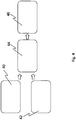
- Fig. 4 shows a flow chart. That flow chart represents the steps “providing mechanical key and spring system” 40 preferably as integral part of wall mount 2. Additionally the step “providing data transfer unit / module, in particularly WiFi module” 42 is carried out. Furthermore, a control unit is provided 44. The control unit receives signals and/or data transmitted via the data transfer unit of wall mount 2. Thus, a warning system (audio, visual, haptic, etc.) is provided 46 since the data and/or signals are received by an outputting device that outputs cotent that represents the alarm information.
- a warning system audio, visual, haptic, etc.
- Fig. 5 shows a flow chart. According to the flow chart the present invention comprises one, multiple or all of the following steps:
Landscapes
- Engineering & Computer Science (AREA)
- General Engineering & Computer Science (AREA)
- Mechanical Engineering (AREA)
- Physics & Mathematics (AREA)
- General Physics & Mathematics (AREA)
- Casings For Electric Apparatus (AREA)
Abstract
a wall means (6) for arranging at a physical wall (8), in particularly a wall of a building,
wherein the wall means (6) comprises at least a first holding element (10) and a second holding element (12),
a first positioning means (14) for attaching to the display device (4) and for coupling with the first holding element (10),
a second positioning means (16) for attaching to the display device (4) and for coupling with the second holding element (12),
wherein at least the first holding element (10) comprises a positioning means detecting means (18) for detecting presence and/or absence of the first positioning means (14) and/or relative movements between the first positioning means (14) and the first holding element (10),
wherein the first holding element (10) comprises a data transfer unit (20) for transmitting data indicating presence and/or absence of the first position means (14) and/or relative movements between the first position means (14) and the first holding element (10) in dependency of signals and/or data provided by the positioning means detecting means (18).
Description
- The present invention refers according to claim 1 to a wall mount for at least or exactly one display device, according to
claim 12 to a method for outputting an alarm via a mobile device and according to claim 13 to a smart home system. - Wall mounts for mounting display devices like televisions to a wall are well known. However, since televisions are very large and heavy it is very dangerous for children if a display device is detached unintentionally. Furthermore, such display devices are often very expensive and need to be theft protected.
- Thus, it is an object of the present invention to increase safety and/or security of wall mounts.
- The before mentioned object is solved by a wall mount for at least one display device, in particularly a television, according to claim 1. Said wall mount comprises at least a first holding element and a second holding element, a first positioning means for attaching to the display device and for coupling with the first holding element, a second positioning means for attaching to the display device and for coupling with the second holding element, wherein at least the first holding element comprises a positioning means detecting means for detecting presence and/or absence of the positioning means and/or relative movements between the position means and the first holding element. The first holding element comprises a data transfer unit for transmitting data indicating presence and/or absence of the position means and/or relative movements between the position means and the first holding element in dependency of signals and/or data provided by the positioning means detecting means and/or the first holding element comprises a signal outputting unit for visually and/or acoustically outputting of signals indicating presence and/or absence of the position means and/or relative movements between the position means and the first holding element in dependency of signals and/or data provided by the positioning means detecting means.
- Each holing element is preferably fixed with at least two screws to a wall member or directly to a wall. The screws are preferably arranged on a horizontal line. The wall mount is preferably a plate or plate-like element. The screws are preferably for mounting the holding elements to the wall means or to the wall arranged on the same horizontal level respectively line or virtual line.
- This solution is beneficial since an alarm can be outputted via a further device, in particularly a smart home device and/or an end-user device, in particularly a mobile phone, a smartwatch, a television, a laptop, a tablet PC, in case the display device is moved with respect to the holding element/s.
- Further preferred embodiments are subject-matter of the dependent claims and/or of the following specification passages.
- The first holding element comprises according to a further preferred embodiment of the present invention an inserting hole section for receiving a positioning means and a form-closure section, wherein the form-closure section extends less in a first direction compared to the inserting hole section, wherein the inserting hole section and the form-closure section are interconnected in such a manner that the a position means can be moved in a second direction from the inserting hole section into the form-closure section and vice versa, wherein the first direction and the second direction are orientated in an angle of 90° to each other. This embodiment is beneficial since the display device can be easily coupled to wall mount since the positioning means fit inside the inserting hole section and reliably lock in the form-closure section.
- The second direction is according to a further preferred embodiment of the present invention orientated in an orientation different from a vertical orientation, in particularly in an angle between 0° and 90°, in particularly in an angle between 15° and 75°, in particularly in an angle between 30° and 60°. This embodiment is beneficial since an impact that is orientated vertically (upwards) does not cause releasing of the position means from the holding elements.
- The detecting means comprises according to a further preferred embodiment of the present invention a movable element, in particularly a rod-like element, which is arranged in a movable, in particularly pivotable, manner at a main structure of the first holding element, wherein the data transfer unit is actuated in dependency of the position of the movable element. This embodiment is beneficial since the movable element acts as indicator and doubtless indicates if a display means is attached to the wall mount or not.
- The movable element moves according to a further preferred embodiment of the present invention from a first position or orientation into a second position or orientation in case the position means is moved from the inserting hole section into the form-closure section. The movable element moves alternatively from a second position or orientation into a first position or orientation in case the position means is moved from the form-closure section into the inserting hole section. The data transfer unit is according to a further preferred embodiment of the present invention actuated in case the movable element is arranged in the first position or orientation or in case the movable element is arranged in the second position or orientation. This embodiment is beneficial since the movable element indirectly confirms that the position means is/are positioned in a desired respectively predefined position.
- A mechanical spring is provided according to a further preferred embodiment of the present invention, wherein the spring provides forces for holding the movable element in a predefined position or orientation, in particularly in the first position or orientation. This embodiment is beneficial since the movable element is always moved into a position spaced apart form the sensor respectively contacting element respectively switch in case the display means is removed from the wall mount.
- The second holding element comprises according to a further preferred embodiment of the present invention an inserting hole section for receiving a positioning means, in particularly the second position means, and a form-closure section, wherein the form-closure section extends less in a first direction compared to the inserting hole section, wherein the inserting hole section and the form-closure section are interconnected in such a manner that the second position means can be moved in a second direction from the inserting hole section into the form-closure section and vice versa, wherein the first direction and the second direction are orientated in an angle of 90° to each other. The second holding element additionally or alternatively comprises a further data transfer unit, a further positioning means detecting means, wherein the further data transfer unit is actuated in case the further position means detecting means detects a movement of a positioning means.
- The data transfer unit and/or the further data transfer unit is/are according to a further preferred embodiment of the present invention connected to a sensor system that detects signals and/or data from a plurality of house infrastructure devices and/or household devices at the same time, wherein the sensor system provides sensor signals and/or sensor data, in particularly in processed manner, to a server device, in particularly a cloud server, wherein the house infrastructure devices preferably comprise a door bell, shutter and/or preferably at least one lamp and/or wherein the household devices preferably comprise an oven, a wash machine, a dish washer, a garbage can, a refrigerator and/or a coffee machine. This embodiment is beneficial since data indicating one or multiple parameters of at least two devices of a smart home system can be outputted, in particularly displayed, at the same time and/or at different times to one or more users. Alternatively, or additionally such data can be uploaded to a server device and/or stored on a local storage means.
- The above-mentioned object is also solved by a method according to
claim 12 for outputting an alarm via a mobile device, in particularly a smartphone or tablet PC. The inventive method preferably comprises at least the step of providing a wall mount according to any of the before mentioned claims, the step of connecting the data transfer unit to a network, in particularly via WiFi/WLAN and/or Bluetooth and/or NFC, the step of connecting the mobile device to the same network, and/or the step of outputting a signal via an outputting means of the mobile device, in particularly a screen and/or a speaker and/or a vibrating element, in case the data transfer unit was actuated. - The above mentioned object is also solved by a smart home system according to claim 13. The smart home system according to claim 13 preferably comprises at least a control unit that receives wirelessly data and/or signals from individual devices, a wall mount according to any of claims 1 to 11, and at least one further device, wherein the further device comprises at least one sensor for detecting a parameter of the device, an outputting device, in particularly a mobile device, in particularly a mobile phone or a tablet PC, wherein the outputting device outputs information in dependency of signals and/or data received from at least one or multiple or all devices of the smart home system. The control unit provides according to a further preferred embodiment of the present invention data to a server device and/or receives data from the server device, wherein the server device preferably processes the data received from the control unit. This embodiment is beneficial since the server device can match the received and/or processed data with data which belong to further smart home systems. Thus, the overall usage can be optimized since learnings from one or multiple systems or from the majority of systems can be used to operate individual systems. It is additionally or alternatively possible to access the data of a specific smart home system via the internet. Thus, an end user can access such data preferably by means of a computer, in particularly a smart phone and/or tablet PC and/or laptop and/or smartwatch.
- Further benefits, goals and features of the present invention will be described by the following specification of the attached figures, in which exemplarily components of the invention are illustrated. Components of the devices, units and methods according to the invention, which match at least essentially with respect to their function can be marked with the same reference sign, wherein such components do not have to be marked or described multiple times with respect to said figures. In the following the invention is just exemplarily described with respect to the attached figures.
- For a more complete understanding of the present invention and advantages thereof, reference is now made to the following description taken in conjunction with the accompanying drawings. The invention is explained in more detail below using an exemplary embodiment which is specified in the schematic figures of the drawings, in which shows:
- Fig. 1
- exemplarily a wall mount according to the present invention and
- fig. 2
- a backside of a display means, wherein multiple position means are shown,
- fig. 3a
- an example of a first holding element,
- fig. 3b
- an example of a second holding element,
- fig. 4
- a flow chart of multiple steps of a method according to the present invention and
- fig. 5
- a further flow chart representing multiple steps of a further method according to the present invention.
-
Fig. 1 shows awall 3. It is possible to mount a wall mount 2 which comprises two ormore holding elements wall 3. However, it is also possible that holdingelements wall 3 or can be mounted to a wall or ceiling. - The
first holding element 10 comprises an insertinghole section 22 and aform closure section 24. The same applies to thesecond holding element 12.Reference number 30 indicates the inserting hole section of thesecond holding element 12 andreference number 32 indicates the form closure section of thesecond holding element 12. -
Fig. 2 shows a backside of a display means 4, in particularly a television. The display means comprises multiple connecting members for housing multiple position means 14, 16. The position means 14, 16 preferably comprises a longitudinal rod, which forms at one end a head, wherein said head preferably has a diameter larger than the other sections of said rod. -
Fig. 3a shows a schematic illustration of first holdingelement 10. The first holding element preferably comprises amovable element 26. Themovable element 26 moves in the direction ofarrow 27 from a second position or orientation into a first position or orientation in case the first position means 14 is moved from the form-closure section 24 into the insertinghole section 22. Due to the movement of movement element 26 aswitch 21 is actuated respectively triggered. Thus, thedata transfer unit 20 is actuated in case themovable element 26 is arranged in the first position or orientation and contacts switch 21. Amechanical spring 28 is preferably provided, wherein thespring 28 provides forces for holding the movable element in a predefined position or orientation, in particularly in the first position or orientation. Thespring 28 can be formed of metal or a polymer material. - Thus, the present invention refers to a wall mount 2 for at least one
display device 4, in particularly a television. Wall mount 2 preferably comprises a wall means 6 for arranging at a physical wall 8, in particularly a wall of a building, wherein the wall means 6 comprises at least afirst holding element 10 and preferably asecond holding element 12. A first positioning means 14 for attaching to thedisplay device 4 and for coupling with the first holdingelement 10. Preferably a second positioning means 16 for attaching to thedisplay device 4 and for coupling with thesecond holding element 12. Thefirst holding element 10 preferably comprises a positioning means detecting means 18 for detecting presence and/or absence of the first positioning means 14 and/or relative movements between the first positioning means 14 and the first holdingelement 10. Thefirst holding element 10 preferably comprises adata transfer unit 20 for transmitting data indicating presence and/or absence of the first position means 14 and/or relative movements between the first position means 14 and the first holdingelement 10 in dependency of signals and/or data provided by the positioning means detecting means 18, and/or the first holdingelement 10 comprises a signal outputting unit for visually and/or acoustically outputting of signals indicating presence and/or absence of the first position means 14 and/or relative movements between the first position means 14 and the first holdingelement 10 in dependency of signals and/or data provided by the positioning means detecting means 18. It is also possible that 3 or 4 or up to 3 or 4 or more than 3 or more than 4 holding elements are provided for holding one or exactly one display device. -
Fig. 4 shows a flow chart. That flow chart represents the steps "providing mechanical key and spring system" 40 preferably as integral part of wall mount 2. Additionally the step "providing data transfer unit / module, in particularly WiFi module" 42 is carried out. Furthermore, a control unit is provided 44. The control unit receives signals and/or data transmitted via the data transfer unit of wall mount 2. Thus, a warning system (audio, visual, haptic, etc.) is provided 46 since the data and/or signals are received by an outputting device that outputs cotent that represents the alarm information. -
Fig. 5 shows a flow chart. According to the flow chart the present invention comprises one, multiple or all of the following steps: - 50: The suspended wall is mounted. Minimum two wall hangers will be used.
- 52: Key lock. The spring system of the wall hanging system (wall mount) uses an installed mechanical key structure.
- 54: Smart home warning system will be provided by the movement of the installed mechanical key structure, wherein the spring system is connected to the data transfer unit.
- 56: The mechanical switch operating ratio will normally be in the off position. When any device is installed on the wall hanging apparatus (wall mount), the mechanical key structure will be activated by the movement of the spring system.
- 58: In case of involuntary intervention (e.g. impact) the wall hanging pin of the device will come out of the suspension peg.
- 60: By means of a mechanical switch position changeover with the attached spring system, the warning system (audible and/or visual, etc.) is switched on.
- 62: The user is informed of the non-conformity in the suspension system
-
- 2
- wall mount
- 3
- wall
- 4
- display device
- 6
- wall means
- 8
- physical wall
- 10
- first holding element
- 12
- second holding element
- 14
- first positioning means
- 16
- second positioning means
- 18
- positioning means detecting means
- 20
- data transfer unit
- 21
- contacting element /switch
- 22
- inserting hole section
- 24
- form-closure section
- 26
- movable element
- 27
- pivoting direction of movable element
- 28
- spring
- 30
- inserting hole section of second holding element
- 32
- form-closure section of second holding element
- 34
- marking
- 36
- fixing element / screw
- 40
- providing mechanical key and spring system
- 42
- providing data transfer unit / module, in particularly WiFi module
- 44
- providing control unit
- 46
- providing warning system (audio, visual, haptic, etc.)
- 50-62
- preferred steps of an usage of the wall mount
Claims (14)
- Wall mount (2) for at least one display device (4), in particularly a television,
at least comprising
a wall means (6) for arranging at a physical wall (8), in particularly a wall of a building, wherein the wall means (6) comprises at least a first holding element (10) and a second holding element (12),
a first positioning means (14) for attaching to the display device (4) and for coupling with the first holding element (10),
a second positioning means (16) for attaching to the display device (4) and for coupling with the second holding element (12),
wherein at least the first holding element (10) comprises a positioning means detecting means (18) for detecting presence and/or absence of the first positioning means (14) and/or relative movements between the first positioning means (14) and the first holding element (10),
wherein the first holding element (10) comprises a data transfer unit (20) for transmitting data indicating presence and/or absence of the first position means (14) and/or relative movements between the first position means (14) and the first holding element (10) in dependency of signals and/or data provided by the positioning means detecting means (18),
and/or
wherein the first holding element (10) comprises a signal outputting unit for visually and/or acoustically outputting of signals indicating presence and/or absence of the first position means (14) and/or relative movements between the first position means (14) and the first holding element (10) in dependency of signals and/or data provided by the positioning means detecting means (18). - Wall mount (1) according to claim 1,
characterized in that
the first holding element (10) comprises an inserting hole section (22) for receiving the first positioning means (14) and a form-closure section (24), wherein the form-closure section (24) extends less in a first direction compared to the inserting hole section (22), wherein the inserting hole section (22) and the form-closure section (24) are interconnected in such a manner that the a first position means (14) can be moved in a second direction from the inserting hole section (22) into the form-closure section (24) and vice versa, wherein the first direction and the second direction are orientated in an angle of 90° to each other. - Wall mount (1) according to claim 1 or 2,
characterized in that
the second direction is orientated in an orientation different from a vertical orientation, in particularly in an angle between 0° and 90°, in particularly in an angle between 15° and 75°, in particularly in an angle between 30° and 60°. - Wall mount (1) according to any of the preceding claims,
characterized in that
the position means detecting means (18) comprises a movable element (26), in particularly a rod-like element, which is arranged in a movable, in particularly pivotable, manner at a main structure of the first holding element (10), wherein the data transfer unit (20) is actuated in dependency of the position of the movable element (26). - Wall mount (1) according to any of the preceding claims,
characterized in that
the movable element (26) moves from a first position or orientation into a second position or orientation in case the first position means (14) is moved from the inserting hole section (22) into the form-closure section (24). - Wall mount (1) according to any of the preceding claims,
characterized in that
the movable element (26) moves from a second position or orientation into a first position or orientation in case the first position means (14) is moved from the form-closure section (24) into the inserting hole section (22). - Wall mount (1) according to any of the preceding claims,
characterized in that
the data transfer unit (20) is actuated in case the movable element (26) is arranged in the first position or orientation or in case the movable element (26) is arranged in the second position or orientation. - Wall mount (1) according to any of the preceding claims,
characterized in that
a mechanical spring (28) is provided, wherein the spring (28) provides forces for holding the movable element in a predefined position or orientation, in particularly in the first position or orientation. - Wall mount (1) according to any of the preceding claims,
characterized in that
the second holding element (12) comprises an inserting hole section (30) for receiving the second positioning means (16) and a form-closure section (32), wherein the form-closure section (32) extends less in a first direction compared to the inserting hole section (30), wherein the inserting hole section (30) and the form-closure section (32) are interconnected in such a manner that the second position means (16) can be moved in a second direction from the inserting hole section (30) into the form-closure section (32) and vice versa, wherein the first direction and the second direction are orientated in an angle of 90° to each other. - Wall mount (1) according to claim 9,
characterized in that
the second holding element (12) comprises a further data transfer unit, a further positioning means detecting means, wherein the further data transfer unit is actuated in case the further position means detecting means detects a movement of a positioning means. - Wall mount (1) according to any of the preceding claims,
characterized in that
the data transfer unit/s is/are connected to a sensor system that detects signals and/or data from a plurality of house infrastructure devices and/or household devices at the same time, wherein the sensor system provides sensor signals and/or sensor data, in particularly in processed manner, to a server device, in particularly a cloud server, wherein the house infrastructure devices preferably comprise a door bell, shutter and/or preferably at least one lamp and/or wherein the household devices preferably comprise an oven, a wash machine, a dish washer, a garbage can, a refrigerator and/or a coffee machine. - Method for outputting an alarm via a mobile device, in particularly a smartphone or tablet PC,
at least comprising the step of providing a wall mount (2) according to any of the before mentioned claims,
the step of connecting the data transfer unit (20) to a network, in particularly via WiFi/WLAN and/or Bluetooth and/or NFC,
the step of connecting the mobile device to the same network,
the step of outputting a signal via an outputting means of the mobile device, in particularly a screen and/or a speaker and/or a vibrating element, in case the data transfer unit was actuated in dependency of a movement of a positioning means. - Smart home system,
at least comprising
a control unit that receives wirelessly data and/or signals from individual devices a wall mount according to any of claims 1 to 11, and
at least one further device, wherein the further device comprises at least one sensor for detecting a parameter of the device
an outputting device, in particularly a mobile device, in particularly a mobile phone or a tablet PC, wherein the outputting device outputs information in dependency of signals and/or data received from at least one or multiple or all devices of the smart home system. - Smart home system,
according to claim 13,
wherein the control unit provides data to a server device and/or receives data from the server device,
wherein the server device preferably processes the data received from the control unit.
Priority Applications (1)
| Application Number | Priority Date | Filing Date | Title |
|---|---|---|---|
| EP18192882.1A EP3620707B1 (en) | 2018-09-06 | 2018-09-06 | Wall mount and smart home system with such a smart wall mount |
Applications Claiming Priority (1)
| Application Number | Priority Date | Filing Date | Title |
|---|---|---|---|
| EP18192882.1A EP3620707B1 (en) | 2018-09-06 | 2018-09-06 | Wall mount and smart home system with such a smart wall mount |
Publications (2)
| Publication Number | Publication Date |
|---|---|
| EP3620707A1 true EP3620707A1 (en) | 2020-03-11 |
| EP3620707B1 EP3620707B1 (en) | 2023-01-11 |
Family
ID=63524116
Family Applications (1)
| Application Number | Title | Priority Date | Filing Date |
|---|---|---|---|
| EP18192882.1A Active EP3620707B1 (en) | 2018-09-06 | 2018-09-06 | Wall mount and smart home system with such a smart wall mount |
Country Status (1)
| Country | Link |
|---|---|
| EP (1) | EP3620707B1 (en) |
Cited By (1)
| Publication number | Priority date | Publication date | Assignee | Title |
|---|---|---|---|---|
| CN112728321A (en) * | 2020-12-29 | 2021-04-30 | 山东高速云南发展有限公司 | Highway warp early warning forecasting device with quick mounting structure |
Citations (1)
| Publication number | Priority date | Publication date | Assignee | Title |
|---|---|---|---|---|
| WO2013145381A1 (en) * | 2012-03-28 | 2013-10-03 | シャープ株式会社 | Bracket, hooking system, hooking method, and display apparatus |
-
2018
- 2018-09-06 EP EP18192882.1A patent/EP3620707B1/en active Active
Patent Citations (1)
| Publication number | Priority date | Publication date | Assignee | Title |
|---|---|---|---|---|
| WO2013145381A1 (en) * | 2012-03-28 | 2013-10-03 | シャープ株式会社 | Bracket, hooking system, hooking method, and display apparatus |
Cited By (2)
| Publication number | Priority date | Publication date | Assignee | Title |
|---|---|---|---|---|
| CN112728321A (en) * | 2020-12-29 | 2021-04-30 | 山东高速云南发展有限公司 | Highway warp early warning forecasting device with quick mounting structure |
| CN112728321B (en) * | 2020-12-29 | 2022-09-27 | 山东高速云南发展有限公司 | Highway warp early warning forecasting device with quick mounting structure |
Also Published As
| Publication number | Publication date |
|---|---|
| EP3620707B1 (en) | 2023-01-11 |
Similar Documents
| Publication | Publication Date | Title |
|---|---|---|
| US8456279B2 (en) | Accelerometer-based CE device wireless access point mapping | |
| CN113272875B (en) | Merchandise display security system and method | |
| US9218732B2 (en) | Integrated flood and temperature sensor for use in a home network environment | |
| KR102310119B1 (en) | Method and apparatus for traffic safety | |
| CA2946042C (en) | Remote talk down to panel, camera and speaker | |
| WO2015044784A2 (en) | Touch-less swipe control | |
| KR102121918B1 (en) | Method and apparatus for event notification in home network system | |
| EP3157200A1 (en) | Security system with graphical alarm notification | |
| US11417195B2 (en) | Location-aware provisioning system for fire alarm system and method therefor | |
| EP3115979B1 (en) | Data collection and processing apparatus and system with burglarproof function, and method | |
| EP3069329B1 (en) | Security panel with virtual sensors | |
| EP3620707B1 (en) | Wall mount and smart home system with such a smart wall mount | |
| WO2009067794A1 (en) | Infrastructure device with modular remote sensors | |
| EP3113137B1 (en) | Security sensor | |
| EP4047579A1 (en) | Security / automation system control panel with short range communication disarming | |
| CN103942903A (en) | Data acquisition processing device, system and method with anti-theft function | |
| TWI670692B (en) | System and method for data collection and analysis and program therefor | |
| CN202196477U (en) | Anti-theft alarm device with behavioural analysis ability | |
| CN105448056A (en) | Alarm button system with pre-alarm function | |
| CN111882844A (en) | Wall-mounted safety shell | |
| CN113611045B (en) | Helmet use control method of electric bicycle and electric bicycle | |
| US9774814B1 (en) | Display device control system | |
| US11540350B2 (en) | Proxy nodes for expanding the functionality of nodes in a wirelessly connected environment | |
| EP3669238A1 (en) | Method to present a user with a menu of ranked building system based upon usage of building systems | |
| KR20090002955A (en) | Security system using RF sensor |
Legal Events
| Date | Code | Title | Description |
|---|---|---|---|
| PUAI | Public reference made under article 153(3) epc to a published international application that has entered the european phase |
Free format text: ORIGINAL CODE: 0009012 |
|
| STAA | Information on the status of an ep patent application or granted ep patent |
Free format text: STATUS: THE APPLICATION HAS BEEN PUBLISHED |
|
| AK | Designated contracting states |
Kind code of ref document: A1 Designated state(s): AL AT BE BG CH CY CZ DE DK EE ES FI FR GB GR HR HU IE IS IT LI LT LU LV MC MK MT NL NO PL PT RO RS SE SI SK SM TR |
|
| AX | Request for extension of the european patent |
Extension state: BA ME |
|
| STAA | Information on the status of an ep patent application or granted ep patent |
Free format text: STATUS: REQUEST FOR EXAMINATION WAS MADE |
|
| 17P | Request for examination filed |
Effective date: 20200909 |
|
| RBV | Designated contracting states (corrected) |
Designated state(s): AL AT BE BG CH CY CZ DE DK EE ES FI FR GB GR HR HU IE IS IT LI LT LU LV MC MK MT NL NO PL PT RO RS SE SI SK SM TR |
|
| RIC1 | Information provided on ipc code assigned before grant |
Ipc: G08B 1/00 20060101ALI20220520BHEP Ipc: F16M 13/02 20060101ALI20220520BHEP Ipc: F16M 11/22 20060101ALI20220520BHEP Ipc: F16M 11/04 20060101AFI20220520BHEP |
|
| GRAP | Despatch of communication of intention to grant a patent |
Free format text: ORIGINAL CODE: EPIDOSNIGR1 |
|
| STAA | Information on the status of an ep patent application or granted ep patent |
Free format text: STATUS: GRANT OF PATENT IS INTENDED |
|
| INTG | Intention to grant announced |
Effective date: 20220811 |
|
| GRAS | Grant fee paid |
Free format text: ORIGINAL CODE: EPIDOSNIGR3 |
|
| GRAA | (expected) grant |
Free format text: ORIGINAL CODE: 0009210 |
|
| STAA | Information on the status of an ep patent application or granted ep patent |
Free format text: STATUS: THE PATENT HAS BEEN GRANTED |
|
| AK | Designated contracting states |
Kind code of ref document: B1 Designated state(s): AL AT BE BG CH CY CZ DE DK EE ES FI FR GB GR HR HU IE IS IT LI LT LU LV MC MK MT NL NO PL PT RO RS SE SI SK SM TR |
|
| REG | Reference to a national code |
Ref country code: GB Ref legal event code: FG4D |
|
| REG | Reference to a national code |
Ref country code: CH Ref legal event code: EP |
|
| REG | Reference to a national code |
Ref country code: DE Ref legal event code: R096 Ref document number: 602018045241 Country of ref document: DE |
|
| REG | Reference to a national code |
Ref country code: IE Ref legal event code: FG4D |
|
| REG | Reference to a national code |
Ref country code: AT Ref legal event code: REF Ref document number: 1543629 Country of ref document: AT Kind code of ref document: T Effective date: 20230215 |
|
| REG | Reference to a national code |
Ref country code: LT Ref legal event code: MG9D |
|
| REG | Reference to a national code |
Ref country code: NL Ref legal event code: MP Effective date: 20230111 |
|
| REG | Reference to a national code |
Ref country code: AT Ref legal event code: MK05 Ref document number: 1543629 Country of ref document: AT Kind code of ref document: T Effective date: 20230111 |
|
| PG25 | Lapsed in a contracting state [announced via postgrant information from national office to epo] |
Ref country code: NL Free format text: LAPSE BECAUSE OF FAILURE TO SUBMIT A TRANSLATION OF THE DESCRIPTION OR TO PAY THE FEE WITHIN THE PRESCRIBED TIME-LIMIT Effective date: 20230111 |
|
| PG25 | Lapsed in a contracting state [announced via postgrant information from national office to epo] |
Ref country code: RS Free format text: LAPSE BECAUSE OF FAILURE TO SUBMIT A TRANSLATION OF THE DESCRIPTION OR TO PAY THE FEE WITHIN THE PRESCRIBED TIME-LIMIT Effective date: 20230111 Ref country code: PT Free format text: LAPSE BECAUSE OF FAILURE TO SUBMIT A TRANSLATION OF THE DESCRIPTION OR TO PAY THE FEE WITHIN THE PRESCRIBED TIME-LIMIT Effective date: 20230511 Ref country code: NO Free format text: LAPSE BECAUSE OF FAILURE TO SUBMIT A TRANSLATION OF THE DESCRIPTION OR TO PAY THE FEE WITHIN THE PRESCRIBED TIME-LIMIT Effective date: 20230411 Ref country code: LV Free format text: LAPSE BECAUSE OF FAILURE TO SUBMIT A TRANSLATION OF THE DESCRIPTION OR TO PAY THE FEE WITHIN THE PRESCRIBED TIME-LIMIT Effective date: 20230111 Ref country code: LT Free format text: LAPSE BECAUSE OF FAILURE TO SUBMIT A TRANSLATION OF THE DESCRIPTION OR TO PAY THE FEE WITHIN THE PRESCRIBED TIME-LIMIT Effective date: 20230111 Ref country code: HR Free format text: LAPSE BECAUSE OF FAILURE TO SUBMIT A TRANSLATION OF THE DESCRIPTION OR TO PAY THE FEE WITHIN THE PRESCRIBED TIME-LIMIT Effective date: 20230111 Ref country code: ES Free format text: LAPSE BECAUSE OF FAILURE TO SUBMIT A TRANSLATION OF THE DESCRIPTION OR TO PAY THE FEE WITHIN THE PRESCRIBED TIME-LIMIT Effective date: 20230111 Ref country code: AT Free format text: LAPSE BECAUSE OF FAILURE TO SUBMIT A TRANSLATION OF THE DESCRIPTION OR TO PAY THE FEE WITHIN THE PRESCRIBED TIME-LIMIT Effective date: 20230111 |
|
| PG25 | Lapsed in a contracting state [announced via postgrant information from national office to epo] |
Ref country code: SE Free format text: LAPSE BECAUSE OF FAILURE TO SUBMIT A TRANSLATION OF THE DESCRIPTION OR TO PAY THE FEE WITHIN THE PRESCRIBED TIME-LIMIT Effective date: 20230111 Ref country code: PL Free format text: LAPSE BECAUSE OF FAILURE TO SUBMIT A TRANSLATION OF THE DESCRIPTION OR TO PAY THE FEE WITHIN THE PRESCRIBED TIME-LIMIT Effective date: 20230111 Ref country code: IS Free format text: LAPSE BECAUSE OF FAILURE TO SUBMIT A TRANSLATION OF THE DESCRIPTION OR TO PAY THE FEE WITHIN THE PRESCRIBED TIME-LIMIT Effective date: 20230511 Ref country code: GR Free format text: LAPSE BECAUSE OF FAILURE TO SUBMIT A TRANSLATION OF THE DESCRIPTION OR TO PAY THE FEE WITHIN THE PRESCRIBED TIME-LIMIT Effective date: 20230412 Ref country code: FI Free format text: LAPSE BECAUSE OF FAILURE TO SUBMIT A TRANSLATION OF THE DESCRIPTION OR TO PAY THE FEE WITHIN THE PRESCRIBED TIME-LIMIT Effective date: 20230111 |
|
| REG | Reference to a national code |
Ref country code: DE Ref legal event code: R097 Ref document number: 602018045241 Country of ref document: DE |
|
| PG25 | Lapsed in a contracting state [announced via postgrant information from national office to epo] |
Ref country code: SM Free format text: LAPSE BECAUSE OF FAILURE TO SUBMIT A TRANSLATION OF THE DESCRIPTION OR TO PAY THE FEE WITHIN THE PRESCRIBED TIME-LIMIT Effective date: 20230111 Ref country code: RO Free format text: LAPSE BECAUSE OF FAILURE TO SUBMIT A TRANSLATION OF THE DESCRIPTION OR TO PAY THE FEE WITHIN THE PRESCRIBED TIME-LIMIT Effective date: 20230111 Ref country code: EE Free format text: LAPSE BECAUSE OF FAILURE TO SUBMIT A TRANSLATION OF THE DESCRIPTION OR TO PAY THE FEE WITHIN THE PRESCRIBED TIME-LIMIT Effective date: 20230111 Ref country code: DK Free format text: LAPSE BECAUSE OF FAILURE TO SUBMIT A TRANSLATION OF THE DESCRIPTION OR TO PAY THE FEE WITHIN THE PRESCRIBED TIME-LIMIT Effective date: 20230111 Ref country code: CZ Free format text: LAPSE BECAUSE OF FAILURE TO SUBMIT A TRANSLATION OF THE DESCRIPTION OR TO PAY THE FEE WITHIN THE PRESCRIBED TIME-LIMIT Effective date: 20230111 |
|
| PGFP | Annual fee paid to national office [announced via postgrant information from national office to epo] |
Ref country code: GB Payment date: 20230920 Year of fee payment: 6 |
|
| PLBE | No opposition filed within time limit |
Free format text: ORIGINAL CODE: 0009261 |
|
| STAA | Information on the status of an ep patent application or granted ep patent |
Free format text: STATUS: NO OPPOSITION FILED WITHIN TIME LIMIT |
|
| PG25 | Lapsed in a contracting state [announced via postgrant information from national office to epo] |
Ref country code: SK Free format text: LAPSE BECAUSE OF FAILURE TO SUBMIT A TRANSLATION OF THE DESCRIPTION OR TO PAY THE FEE WITHIN THE PRESCRIBED TIME-LIMIT Effective date: 20230111 |
|
| PGFP | Annual fee paid to national office [announced via postgrant information from national office to epo] |
Ref country code: DE Payment date: 20230920 Year of fee payment: 6 |
|
| 26N | No opposition filed |
Effective date: 20231012 |
|
| PG25 | Lapsed in a contracting state [announced via postgrant information from national office to epo] |
Ref country code: SI Free format text: LAPSE BECAUSE OF FAILURE TO SUBMIT A TRANSLATION OF THE DESCRIPTION OR TO PAY THE FEE WITHIN THE PRESCRIBED TIME-LIMIT Effective date: 20230111 |
|
| REG | Reference to a national code |
Ref country code: CH Ref legal event code: PL |
|
| PG25 | Lapsed in a contracting state [announced via postgrant information from national office to epo] |
Ref country code: LU Free format text: LAPSE BECAUSE OF NON-PAYMENT OF DUE FEES Effective date: 20230906 |
|
| REG | Reference to a national code |
Ref country code: BE Ref legal event code: MM Effective date: 20230930 |
|
| PG25 | Lapsed in a contracting state [announced via postgrant information from national office to epo] |
Ref country code: LU Free format text: LAPSE BECAUSE OF NON-PAYMENT OF DUE FEES Effective date: 20230906 Ref country code: IT Free format text: LAPSE BECAUSE OF FAILURE TO SUBMIT A TRANSLATION OF THE DESCRIPTION OR TO PAY THE FEE WITHIN THE PRESCRIBED TIME-LIMIT Effective date: 20230111 Ref country code: MC Free format text: LAPSE BECAUSE OF FAILURE TO SUBMIT A TRANSLATION OF THE DESCRIPTION OR TO PAY THE FEE WITHIN THE PRESCRIBED TIME-LIMIT Effective date: 20230111 |
|
| REG | Reference to a national code |
Ref country code: IE Ref legal event code: MM4A |
|
| PG25 | Lapsed in a contracting state [announced via postgrant information from national office to epo] |
Ref country code: IE Free format text: LAPSE BECAUSE OF NON-PAYMENT OF DUE FEES Effective date: 20230906 |
|
| PG25 | Lapsed in a contracting state [announced via postgrant information from national office to epo] |
Ref country code: CH Free format text: LAPSE BECAUSE OF NON-PAYMENT OF DUE FEES Effective date: 20230930 |
|
| PG25 | Lapsed in a contracting state [announced via postgrant information from national office to epo] |
Ref country code: IE Free format text: LAPSE BECAUSE OF NON-PAYMENT OF DUE FEES Effective date: 20230906 Ref country code: FR Free format text: LAPSE BECAUSE OF NON-PAYMENT OF DUE FEES Effective date: 20230930 Ref country code: CH Free format text: LAPSE BECAUSE OF NON-PAYMENT OF DUE FEES Effective date: 20230930 |
|
| PG25 | Lapsed in a contracting state [announced via postgrant information from national office to epo] |
Ref country code: BE Free format text: LAPSE BECAUSE OF NON-PAYMENT OF DUE FEES Effective date: 20230930 |
|
| PG25 | Lapsed in a contracting state [announced via postgrant information from national office to epo] |
Ref country code: BG Free format text: LAPSE BECAUSE OF FAILURE TO SUBMIT A TRANSLATION OF THE DESCRIPTION OR TO PAY THE FEE WITHIN THE PRESCRIBED TIME-LIMIT Effective date: 20230111 |
|
| PG25 | Lapsed in a contracting state [announced via postgrant information from national office to epo] |
Ref country code: BG Free format text: LAPSE BECAUSE OF FAILURE TO SUBMIT A TRANSLATION OF THE DESCRIPTION OR TO PAY THE FEE WITHIN THE PRESCRIBED TIME-LIMIT Effective date: 20230111 |
|
| REG | Reference to a national code |
Ref country code: DE Ref legal event code: R119 Ref document number: 602018045241 Country of ref document: DE |
|
| GBPC | Gb: european patent ceased through non-payment of renewal fee |
Effective date: 20240906 |
|
| PG25 | Lapsed in a contracting state [announced via postgrant information from national office to epo] |
Ref country code: DE Free format text: LAPSE BECAUSE OF NON-PAYMENT OF DUE FEES Effective date: 20250401 |
|
| PG25 | Lapsed in a contracting state [announced via postgrant information from national office to epo] |
Ref country code: GB Free format text: LAPSE BECAUSE OF NON-PAYMENT OF DUE FEES Effective date: 20240906 |
|
| PG25 | Lapsed in a contracting state [announced via postgrant information from national office to epo] |
Ref country code: CY Free format text: LAPSE BECAUSE OF FAILURE TO SUBMIT A TRANSLATION OF THE DESCRIPTION OR TO PAY THE FEE WITHIN THE PRESCRIBED TIME-LIMIT; INVALID AB INITIO Effective date: 20180906 |
|
| PG25 | Lapsed in a contracting state [announced via postgrant information from national office to epo] |
Ref country code: HU Free format text: LAPSE BECAUSE OF FAILURE TO SUBMIT A TRANSLATION OF THE DESCRIPTION OR TO PAY THE FEE WITHIN THE PRESCRIBED TIME-LIMIT; INVALID AB INITIO Effective date: 20180906 |
|
| PGFP | Annual fee paid to national office [announced via postgrant information from national office to epo] |
Ref country code: TR Payment date: 20250829 Year of fee payment: 8 |