EP3620655A1 - Linear compressor - Google Patents
Linear compressor Download PDFInfo
- Publication number
- EP3620655A1 EP3620655A1 EP19189568.9A EP19189568A EP3620655A1 EP 3620655 A1 EP3620655 A1 EP 3620655A1 EP 19189568 A EP19189568 A EP 19189568A EP 3620655 A1 EP3620655 A1 EP 3620655A1
- Authority
- EP
- European Patent Office
- Prior art keywords
- filter
- cylinder
- linear compressor
- refrigerant
- oil
- Prior art date
- Legal status (The legal status is an assumption and is not a legal conclusion. Google has not performed a legal analysis and makes no representation as to the accuracy of the status listed.)
- Granted
Links
- 239000003507 refrigerant Substances 0.000 claims abstract description 119
- 239000005871 repellent Substances 0.000 claims abstract description 55
- 230000006835 compression Effects 0.000 claims abstract description 32
- 238000007906 compression Methods 0.000 claims abstract description 32
- 229920000139 polyethylene terephthalate Polymers 0.000 claims description 11
- 239000005020 polyethylene terephthalate Substances 0.000 claims description 11
- 239000000463 material Substances 0.000 claims description 9
- 239000000835 fiber Substances 0.000 claims description 6
- 229910052751 metal Inorganic materials 0.000 claims description 6
- 239000002184 metal Substances 0.000 claims description 6
- -1 polyethylene terephthalate Polymers 0.000 claims description 5
- 230000007423 decrease Effects 0.000 claims description 4
- 229920006351 engineering plastic Polymers 0.000 claims description 2
- 239000007789 gas Substances 0.000 description 85
- 230000008878 coupling Effects 0.000 description 17
- 238000010168 coupling process Methods 0.000 description 17
- 238000005859 coupling reaction Methods 0.000 description 17
- 239000011247 coating layer Substances 0.000 description 16
- 239000000126 substance Substances 0.000 description 15
- 238000007789 sealing Methods 0.000 description 14
- 238000000034 method Methods 0.000 description 12
- 230000008569 process Effects 0.000 description 12
- 239000007769 metal material Substances 0.000 description 6
- 239000003795 chemical substances by application Substances 0.000 description 5
- 238000001914 filtration Methods 0.000 description 5
- 238000004804 winding Methods 0.000 description 4
- 230000000903 blocking effect Effects 0.000 description 3
- 239000010935 stainless steel Substances 0.000 description 3
- 229910001220 stainless steel Inorganic materials 0.000 description 3
- 239000010419 fine particle Substances 0.000 description 2
- 238000003475 lamination Methods 0.000 description 2
- 239000000203 mixture Substances 0.000 description 2
- 229920001343 polytetrafluoroethylene Polymers 0.000 description 2
- 239000004810 polytetrafluoroethylene Substances 0.000 description 2
- 125000006850 spacer group Chemical group 0.000 description 2
- 229910000838 Al alloy Inorganic materials 0.000 description 1
- 229910001369 Brass Inorganic materials 0.000 description 1
- 229910001111 Fine metal Inorganic materials 0.000 description 1
- 230000004308 accommodation Effects 0.000 description 1
- 230000009471 action Effects 0.000 description 1
- 239000000956 alloy Substances 0.000 description 1
- 229910052782 aluminium Inorganic materials 0.000 description 1
- XAGFODPZIPBFFR-UHFFFAOYSA-N aluminium Chemical compound [Al] XAGFODPZIPBFFR-UHFFFAOYSA-N 0.000 description 1
- 230000000712 assembly Effects 0.000 description 1
- 238000000429 assembly Methods 0.000 description 1
- 239000010951 brass Substances 0.000 description 1
- 230000008859 change Effects 0.000 description 1
- 239000000470 constituent Substances 0.000 description 1
- 238000001816 cooling Methods 0.000 description 1
- 230000000694 effects Effects 0.000 description 1
- 238000001746 injection moulding Methods 0.000 description 1
- 239000012528 membrane Substances 0.000 description 1
- 230000002093 peripheral effect Effects 0.000 description 1
- 238000001556 precipitation Methods 0.000 description 1
Images


Classifications
-
- F—MECHANICAL ENGINEERING; LIGHTING; HEATING; WEAPONS; BLASTING
- F04—POSITIVE - DISPLACEMENT MACHINES FOR LIQUIDS; PUMPS FOR LIQUIDS OR ELASTIC FLUIDS
- F04B—POSITIVE-DISPLACEMENT MACHINES FOR LIQUIDS; PUMPS
- F04B35/00—Piston pumps specially adapted for elastic fluids and characterised by the driving means to their working members, or by combination with, or adaptation to, specific driving engines or motors, not otherwise provided for
- F04B35/04—Piston pumps specially adapted for elastic fluids and characterised by the driving means to their working members, or by combination with, or adaptation to, specific driving engines or motors, not otherwise provided for the means being electric
-
- F—MECHANICAL ENGINEERING; LIGHTING; HEATING; WEAPONS; BLASTING
- F04—POSITIVE - DISPLACEMENT MACHINES FOR LIQUIDS; PUMPS FOR LIQUIDS OR ELASTIC FLUIDS
- F04B—POSITIVE-DISPLACEMENT MACHINES FOR LIQUIDS; PUMPS
- F04B53/00—Component parts, details or accessories not provided for in, or of interest apart from, groups F04B1/00 - F04B23/00 or F04B39/00 - F04B47/00
- F04B53/20—Filtering
-
- F—MECHANICAL ENGINEERING; LIGHTING; HEATING; WEAPONS; BLASTING
- F04—POSITIVE - DISPLACEMENT MACHINES FOR LIQUIDS; PUMPS FOR LIQUIDS OR ELASTIC FLUIDS
- F04B—POSITIVE-DISPLACEMENT MACHINES FOR LIQUIDS; PUMPS
- F04B35/00—Piston pumps specially adapted for elastic fluids and characterised by the driving means to their working members, or by combination with, or adaptation to, specific driving engines or motors, not otherwise provided for
- F04B35/04—Piston pumps specially adapted for elastic fluids and characterised by the driving means to their working members, or by combination with, or adaptation to, specific driving engines or motors, not otherwise provided for the means being electric
- F04B35/045—Piston pumps specially adapted for elastic fluids and characterised by the driving means to their working members, or by combination with, or adaptation to, specific driving engines or motors, not otherwise provided for the means being electric using solenoids
-
- B—PERFORMING OPERATIONS; TRANSPORTING
- B01—PHYSICAL OR CHEMICAL PROCESSES OR APPARATUS IN GENERAL
- B01D—SEPARATION
- B01D39/00—Filtering material for liquid or gaseous fluids
- B01D39/14—Other self-supporting filtering material ; Other filtering material
- B01D39/16—Other self-supporting filtering material ; Other filtering material of organic material, e.g. synthetic fibres
- B01D39/1692—Other shaped material, e.g. perforated or porous sheets
-
- B—PERFORMING OPERATIONS; TRANSPORTING
- B01—PHYSICAL OR CHEMICAL PROCESSES OR APPARATUS IN GENERAL
- B01D—SEPARATION
- B01D39/00—Filtering material for liquid or gaseous fluids
- B01D39/14—Other self-supporting filtering material ; Other filtering material
- B01D39/20—Other self-supporting filtering material ; Other filtering material of inorganic material, e.g. asbestos paper, metallic filtering material of non-woven wires
- B01D39/2027—Metallic material
- B01D39/2041—Metallic material the material being filamentary or fibrous
-
- B—PERFORMING OPERATIONS; TRANSPORTING
- B01—PHYSICAL OR CHEMICAL PROCESSES OR APPARATUS IN GENERAL
- B01D—SEPARATION
- B01D46/00—Filters or filtering processes specially modified for separating dispersed particles from gases or vapours
- B01D46/0002—Casings; Housings; Frame constructions
- B01D46/0005—Mounting of filtering elements within casings, housings or frames
-
- B—PERFORMING OPERATIONS; TRANSPORTING
- B01—PHYSICAL OR CHEMICAL PROCESSES OR APPARATUS IN GENERAL
- B01D—SEPARATION
- B01D46/00—Filters or filtering processes specially modified for separating dispersed particles from gases or vapours
- B01D46/10—Particle separators, e.g. dust precipitators, using filter plates, sheets or pads having plane surfaces
- B01D46/106—Ring-shaped filtering elements
-
- B—PERFORMING OPERATIONS; TRANSPORTING
- B01—PHYSICAL OR CHEMICAL PROCESSES OR APPARATUS IN GENERAL
- B01D—SEPARATION
- B01D69/00—Semi-permeable membranes for separation processes or apparatus characterised by their form, structure or properties; Manufacturing processes specially adapted therefor
- B01D69/02—Semi-permeable membranes for separation processes or apparatus characterised by their form, structure or properties; Manufacturing processes specially adapted therefor characterised by their properties
-
- B—PERFORMING OPERATIONS; TRANSPORTING
- B01—PHYSICAL OR CHEMICAL PROCESSES OR APPARATUS IN GENERAL
- B01D—SEPARATION
- B01D69/00—Semi-permeable membranes for separation processes or apparatus characterised by their form, structure or properties; Manufacturing processes specially adapted therefor
- B01D69/12—Composite membranes; Ultra-thin membranes
- B01D69/1213—Laminated layers
-
- B—PERFORMING OPERATIONS; TRANSPORTING
- B32—LAYERED PRODUCTS
- B32B—LAYERED PRODUCTS, i.e. PRODUCTS BUILT-UP OF STRATA OF FLAT OR NON-FLAT, e.g. CELLULAR OR HONEYCOMB, FORM
- B32B27/00—Layered products comprising a layer of synthetic resin
- B32B27/12—Layered products comprising a layer of synthetic resin next to a fibrous or filamentary layer
-
- B—PERFORMING OPERATIONS; TRANSPORTING
- B32—LAYERED PRODUCTS
- B32B—LAYERED PRODUCTS, i.e. PRODUCTS BUILT-UP OF STRATA OF FLAT OR NON-FLAT, e.g. CELLULAR OR HONEYCOMB, FORM
- B32B27/00—Layered products comprising a layer of synthetic resin
- B32B27/36—Layered products comprising a layer of synthetic resin comprising polyesters
-
- B—PERFORMING OPERATIONS; TRANSPORTING
- B32—LAYERED PRODUCTS
- B32B—LAYERED PRODUCTS, i.e. PRODUCTS BUILT-UP OF STRATA OF FLAT OR NON-FLAT, e.g. CELLULAR OR HONEYCOMB, FORM
- B32B5/00—Layered products characterised by the non- homogeneity or physical structure, i.e. comprising a fibrous, filamentary, particulate or foam layer; Layered products characterised by having a layer differing constitutionally or physically in different parts
- B32B5/02—Layered products characterised by the non- homogeneity or physical structure, i.e. comprising a fibrous, filamentary, particulate or foam layer; Layered products characterised by having a layer differing constitutionally or physically in different parts characterised by structural features of a fibrous or filamentary layer
-
- F—MECHANICAL ENGINEERING; LIGHTING; HEATING; WEAPONS; BLASTING
- F04—POSITIVE - DISPLACEMENT MACHINES FOR LIQUIDS; PUMPS FOR LIQUIDS OR ELASTIC FLUIDS
- F04B—POSITIVE-DISPLACEMENT MACHINES FOR LIQUIDS; PUMPS
- F04B39/00—Component parts, details, or accessories, of pumps or pumping systems specially adapted for elastic fluids, not otherwise provided for in, or of interest apart from, groups F04B25/00 - F04B37/00
- F04B39/12—Casings; Cylinders; Cylinder heads; Fluid connections
- F04B39/122—Cylinder block
-
- F—MECHANICAL ENGINEERING; LIGHTING; HEATING; WEAPONS; BLASTING
- F04—POSITIVE - DISPLACEMENT MACHINES FOR LIQUIDS; PUMPS FOR LIQUIDS OR ELASTIC FLUIDS
- F04B—POSITIVE-DISPLACEMENT MACHINES FOR LIQUIDS; PUMPS
- F04B39/00—Component parts, details, or accessories, of pumps or pumping systems specially adapted for elastic fluids, not otherwise provided for in, or of interest apart from, groups F04B25/00 - F04B37/00
- F04B39/12—Casings; Cylinders; Cylinder heads; Fluid connections
- F04B39/126—Cylinder liners
-
- F—MECHANICAL ENGINEERING; LIGHTING; HEATING; WEAPONS; BLASTING
- F04—POSITIVE - DISPLACEMENT MACHINES FOR LIQUIDS; PUMPS FOR LIQUIDS OR ELASTIC FLUIDS
- F04B—POSITIVE-DISPLACEMENT MACHINES FOR LIQUIDS; PUMPS
- F04B39/00—Component parts, details, or accessories, of pumps or pumping systems specially adapted for elastic fluids, not otherwise provided for in, or of interest apart from, groups F04B25/00 - F04B37/00
- F04B39/16—Filtration; Moisture separation
-
- B—PERFORMING OPERATIONS; TRANSPORTING
- B01—PHYSICAL OR CHEMICAL PROCESSES OR APPARATUS IN GENERAL
- B01D—SEPARATION
- B01D2239/00—Aspects relating to filtering material for liquid or gaseous fluids
- B01D2239/04—Additives and treatments of the filtering material
- B01D2239/0414—Surface modifiers, e.g. comprising ion exchange groups
- B01D2239/0421—Rendering the filter material hydrophilic
-
- B—PERFORMING OPERATIONS; TRANSPORTING
- B01—PHYSICAL OR CHEMICAL PROCESSES OR APPARATUS IN GENERAL
- B01D—SEPARATION
- B01D2239/00—Aspects relating to filtering material for liquid or gaseous fluids
- B01D2239/04—Additives and treatments of the filtering material
- B01D2239/0471—Surface coating material
- B01D2239/0478—Surface coating material on a layer of the filter
-
- B—PERFORMING OPERATIONS; TRANSPORTING
- B01—PHYSICAL OR CHEMICAL PROCESSES OR APPARATUS IN GENERAL
- B01D—SEPARATION
- B01D2239/00—Aspects relating to filtering material for liquid or gaseous fluids
- B01D2239/06—Filter cloth, e.g. knitted, woven non-woven; self-supported material
- B01D2239/065—More than one layer present in the filtering material
-
- B—PERFORMING OPERATIONS; TRANSPORTING
- B01—PHYSICAL OR CHEMICAL PROCESSES OR APPARATUS IN GENERAL
- B01D—SEPARATION
- B01D2275/00—Filter media structures for filters specially adapted for separating dispersed particles from gases or vapours
- B01D2275/10—Multiple layers
-
- B—PERFORMING OPERATIONS; TRANSPORTING
- B01—PHYSICAL OR CHEMICAL PROCESSES OR APPARATUS IN GENERAL
- B01D—SEPARATION
- B01D2275/00—Filter media structures for filters specially adapted for separating dispersed particles from gases or vapours
- B01D2275/20—Shape of filtering material
- B01D2275/202—Disc-shaped filter elements
-
- B—PERFORMING OPERATIONS; TRANSPORTING
- B01—PHYSICAL OR CHEMICAL PROCESSES OR APPARATUS IN GENERAL
- B01D—SEPARATION
- B01D2315/00—Details relating to the membrane module operation
- B01D2315/08—Fully permeating type; Dead-end filtration
-
- B—PERFORMING OPERATIONS; TRANSPORTING
- B01—PHYSICAL OR CHEMICAL PROCESSES OR APPARATUS IN GENERAL
- B01D—SEPARATION
- B01D2325/00—Details relating to properties of membranes
- B01D2325/30—Chemical resistance
-
- B—PERFORMING OPERATIONS; TRANSPORTING
- B01—PHYSICAL OR CHEMICAL PROCESSES OR APPARATUS IN GENERAL
- B01D—SEPARATION
- B01D46/00—Filters or filtering processes specially modified for separating dispersed particles from gases or vapours
-
- B—PERFORMING OPERATIONS; TRANSPORTING
- B01—PHYSICAL OR CHEMICAL PROCESSES OR APPARATUS IN GENERAL
- B01D—SEPARATION
- B01D46/00—Filters or filtering processes specially modified for separating dispersed particles from gases or vapours
- B01D46/52—Particle separators, e.g. dust precipitators, using filters embodying folded corrugated or wound sheet material
-
- B—PERFORMING OPERATIONS; TRANSPORTING
- B01—PHYSICAL OR CHEMICAL PROCESSES OR APPARATUS IN GENERAL
- B01D—SEPARATION
- B01D61/00—Processes of separation using semi-permeable membranes, e.g. dialysis, osmosis or ultrafiltration; Apparatus, accessories or auxiliary operations specially adapted therefor
- B01D61/14—Ultrafiltration; Microfiltration
- B01D61/147—Microfiltration
-
- B—PERFORMING OPERATIONS; TRANSPORTING
- B01—PHYSICAL OR CHEMICAL PROCESSES OR APPARATUS IN GENERAL
- B01D—SEPARATION
- B01D71/00—Semi-permeable membranes for separation processes or apparatus characterised by the material; Manufacturing processes specially adapted therefor
- B01D71/02—Inorganic material
-
- B—PERFORMING OPERATIONS; TRANSPORTING
- B01—PHYSICAL OR CHEMICAL PROCESSES OR APPARATUS IN GENERAL
- B01D—SEPARATION
- B01D71/00—Semi-permeable membranes for separation processes or apparatus characterised by the material; Manufacturing processes specially adapted therefor
- B01D71/06—Organic material
- B01D71/30—Polyalkenyl halides
- B01D71/32—Polyalkenyl halides containing fluorine atoms
- B01D71/36—Polytetrafluoroethene
-
- B—PERFORMING OPERATIONS; TRANSPORTING
- B01—PHYSICAL OR CHEMICAL PROCESSES OR APPARATUS IN GENERAL
- B01D—SEPARATION
- B01D71/00—Semi-permeable membranes for separation processes or apparatus characterised by the material; Manufacturing processes specially adapted therefor
- B01D71/06—Organic material
- B01D71/48—Polyesters
-
- B—PERFORMING OPERATIONS; TRANSPORTING
- B32—LAYERED PRODUCTS
- B32B—LAYERED PRODUCTS, i.e. PRODUCTS BUILT-UP OF STRATA OF FLAT OR NON-FLAT, e.g. CELLULAR OR HONEYCOMB, FORM
- B32B2307/00—Properties of the layers or laminate
- B32B2307/70—Other properties
- B32B2307/724—Permeability to gases, adsorption
-
- F—MECHANICAL ENGINEERING; LIGHTING; HEATING; WEAPONS; BLASTING
- F04—POSITIVE - DISPLACEMENT MACHINES FOR LIQUIDS; PUMPS FOR LIQUIDS OR ELASTIC FLUIDS
- F04B—POSITIVE-DISPLACEMENT MACHINES FOR LIQUIDS; PUMPS
- F04B39/00—Component parts, details, or accessories, of pumps or pumping systems specially adapted for elastic fluids, not otherwise provided for in, or of interest apart from, groups F04B25/00 - F04B37/00
- F04B39/02—Lubrication
- F04B39/0284—Constructional details, e.g. reservoirs in the casing
- F04B39/0292—Lubrication of pistons or cylinders
-
- F—MECHANICAL ENGINEERING; LIGHTING; HEATING; WEAPONS; BLASTING
- F04—POSITIVE - DISPLACEMENT MACHINES FOR LIQUIDS; PUMPS FOR LIQUIDS OR ELASTIC FLUIDS
- F04B—POSITIVE-DISPLACEMENT MACHINES FOR LIQUIDS; PUMPS
- F04B53/00—Component parts, details or accessories not provided for in, or of interest apart from, groups F04B1/00 - F04B23/00 or F04B39/00 - F04B47/00
- F04B53/18—Lubricating
Definitions
- the present invention relates to a linear compressor.
- a compressor is a mechanical device that receives power from a power generating device such as an electric motor or a turbine to increase pressure by compressing air, refrigerant or various other operating gases, and are used throughout the household appliance or industry.
- a power generating device such as an electric motor or a turbine to increase pressure by compressing air, refrigerant or various other operating gases, and are used throughout the household appliance or industry.
- Such compressors can be classified into reciprocating compressors, rotary compressors, and scroll compressors.
- the linear compressor is configured to suck and compress the refrigerant while the piston is linearly reciprocated within a cylinder by a linear motor in a closed shell and then discharge the refrigerant.
- Patent Document 1 Korean Patent Publication No. 10-2018-0039959 (April 19, 2018 )
- a gas bearing in which a refrigerant gas is supplied in a space between a cylinder and a piston to perform a bearing function is disclosed.
- the refrigerant gas flows to an outer circumferential surface of the piston through a nozzle provided in the cylinder to act as a bearing in the reciprocating piston.
- the cylinder nozzle may be blocked by oil or a mixture of the oil and dusts to significantly reduce a function of the gas bearing.
- a thread made of a polyethylene terephthalate (PET) may be wound around a gas inflow part provided on an outer circumferential surface of the cylinder and thus used as a precipitation filter-type filter member.
- PET polyethylene terephthalate
- the tension of the filer may be reduced to significantly deteriorate the filtering performance as time elapses.
- the blocking of the cylinder nozzle becomes serious due to the oil or the mixture of the oil and the dusts.
- Embodiments provide a linear compressor including a cylinder filter that is capable of filtering foreign substances contained in a refrigerant gas while adjusting a flow rate of the refrigerant gas used as a gas bearing.
- Embodiments also provide a linear compressor which is capable of preventing a nozzle from being blocked while maintaining performance of a gas bearing even though a diameter of the nozzle or the number of nozzles, through which a refrigerant gas is introduced into a cylinder, is reduced.
- Embodiments also provide a linear compressor in which foreign substances contained in a refrigerant gas are previously filtered before the refrigerant gas is introduced into a nozzle provided in the cylinder to prevent the nozzle from being blocked.
- Embodiments also provide a linear compressor in which blocking of a nozzle is effectively prevented through a simple process without changing a structure of an existing compressor.
- a linear compressor includes: a cylinder configured to define a compression space for a refrigerant; a nozzle which is provided in the cylinder and through which a portion of the refrigerant introduced into the compression space passes; and a cylinder filter installed in the cylinder and disposed at an inlet-side of the nozzle.
- at least one or more surfaces of the cylinder filter may be oil-repellent coated to filter oil or foreign substances contained in the refrigerant gas by using the filter, thereby preventing the filter from being blocked.
- a gas inflow part recessed inward from an outer circumferential surface of the cylinder in a radial direction may be provided in the cylinder, and the nozzle may pass from an inner surface of the gas inflow part to an inner circumferential surface of the cylinder.
- the cylinder filter may include: a first filter installed inside the gas inflow part; and a second filter installed at an outlet-side of the first filter inside the gas inflow part, wherein a surface corresponding to an inlet-side of the first filter may be oil-repellent coated.
- a surface corresponding to an inlet-side of the first filter may be oil-repellent coated.
- the first filter may be disposed to be laminated with the second filter, and an outlet-side of the second filter may be connected to the inlet-side of the nozzle.
- the gas inflow part may include: a first recess part recessed inward from the outer circumferential surface of the cylinder in the radial direction; a second recess part further recessed inward from the first recess part in the radial direction, wherein the first filter is disposed in the first recess part, and the second filter is disposed in the second recess part.
- the first recess part may extend along the outer circumferential surface of the cylinder in a circumferential direction to provide a circular band shape, and the second recess part may be recessed inward from a central point of a bottom surface of the first recess part in the radial direction.
- the first filter may include a metal fiber filter having a plurality of filter holes
- the second filter may include a filter made of a polyethylene terephthalate (PET) material.
- PET polyethylene terephthalate
- a gas inflow part passing from an outer circumferential surface to an inner circumferential surface of the cylinder may be provided in the cylinder, and a plate in which the nozzle is provided may be disposed inside the gas inflow part.
- the gas inflow part may include: a seating groove recessed inward from the outer circumferential surface of the cylinder in a radial direction; and a through-hole passing from the seating groove to the inner circumferential surface of the cylinder, wherein the plate may be seated in the seating groove.
- the cylinder filter may be laminated on the plate inside the seating groove, and a surface corresponding to an inlet-side of the cylinder filter may be oil-repellent coated.
- the cylinder filter may be laminated on the plate inside the seating groove, and a surface corresponding to an outlet-side of the cylinder filter may be oil-repellent coated.
- a portion of the refrigerant discharged from the compression space may pass through the cylinder filter and be introduced into the through-hole of the gas inflow part through the nozzle of the plate.
- the cylinder filter may include a metal fiber filter having a plurality of filter holes, and the plate may be made of an engineering plastic material.
- the linear compressor may further include: a frame body configured to accommodate the cylinder, the frame body extending in an axial direction; a frame flange extending from the frame body in a radial direction; and a frame extending from the frame flange to the frame body, the frame being provided as a frame connection part having a gas hole therein.
- the linear compressor may further include a filter assembly installed at an inlet-side of the gas hole to filter foreign substances of the refrigerant to be introduced into the gas hole, wherein the filter assembly may be installed in a filter groove in which a front surface of the frame flange is recessed backward.
- the filter assembly may include: a filter bracket including a refrigerant inlet part and a refrigerant outlet part, the filter bracket having an accommodation space therein; a discharge filter disposed inside the filter bracket, the discharge filter having a lipophilic property; a first support member disposed at an inlet-side of the discharge filter inside the filter bracket; and a second support member disposed at an outlet-side of the discharge filter inside the filter bracket.
- a surface corresponding to the inlet-side or outlet-side of the discharge filter may be oil-repellent coated to previously filter the foreign substances contained in the refrigerant gas before the refrigerant gas is introduced into the nozzle provided in the cylinder, thereby preventing the nozzle from being blocked.
- the discharge filter may include a first filter contacting the first support member and a second filter disposed at the outlet-side of the first filter to contact the second support member, and a surface corresponding to the inlet-side or outlet-side of the first filter may be oil-repellent coated.
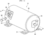
- FIG. 1 is a perspective view of a linear compressor according to a first embodiment
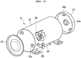
- FIG. 2 is a view illustrating a state in which a shell and a shell cover are separated from each other in the linear compressor of FIG. 1 .
- a linear compressor 10 includes a shell 101 and shell covers 102 and 103 coupled to the shell 101.
- each of the shell covers 102 and 103 may be understood as one component of the shell 101.
- a leg 50 may be coupled to a lower portion of the shell 101.
- the leg 50 may be coupled to a base of a product in which the linear compressor 10 is installed.
- the product may include a refrigerator, and the base may include a machine room base of the refrigerator.
- the product may include an outdoor unit of an air conditioner, and the base may include a base of the outdoor unit.
- the shell 101 may have an approximately cylindrical shape and be disposed to lie in a horizontal direction or an axial direction. In FIG. 1 , the shell 101 may extend in the horizontal direction and have a relatively low height in a radial direction. That is, since the linear compressor 10 has a low height, for example, when For example the linear compressor 10 is installed in the machine room base of the refrigerator, a machine room may be reduced in height.
- a terminal 108 may be installed on an outer surface of the shell 101.
- the terminal 108 may be understood as a component for transferring external power to a motor assembly (see reference numeral 140 of FIG. 3 ) of the linear compressor 10.
- the terminal 108 may be connected to a lead line of a coil (see reference numeral 141c of FIG. 3 ).
- a bracket 109 is installed outside the terminal 108.
- the bracket 109 may include a plurality of brackets surrounding the terminal 108.
- the bracket 109 may protect the terminal 108 against an external impact and the like.
- Both sides of the shell 101 may be opened.
- the shell covers 102 and 103 may be coupled to both the opened sides of the shell 101.
- the shell covers 102 and 103 include a first shell cover 102 coupled to one opened side of the shell 101 and a second shell cover 103 coupled to the other opened side of the shell 101.
- An inner space of the shell 101 may be sealed by the shell covers 102 and 103.
- the first shell cover 102 may be disposed at a right portion of the linear compressor 10, and the second shell cover 103 may be disposed at a left portion of the linear compressor 10. That is to say, the first and second shell covers 102 and 103 may be disposed to face each other.
- the linear compressor 10 further includes a plurality of pipes 104, 105, and 106, which are provided in the shell 101 or the shell covers 102 and 103 to suction, discharge, or inject the refrigerant.
- the plurality of pipes 104, 105, and 106 include a suction pipe 104 through which the refrigerant is suctioned into the linear compressor 10, a discharge pipe 105 through which the compressed refrigerant is discharged from the linear compressor 10, and a process pipe through which the refrigerant is supplemented to the linear compressor 10.
- the suction pipe 104 may be coupled to the first shell cover 102.
- the refrigerant may be suctioned into the linear compressor 10 through the suction pipe 104 in an axial direction.
- the discharge pipe 105 may be coupled to an outer circumferential surface of the shell 101.
- the refrigerant suctioned through the suction pipe 104 may flow in the axial direction and then be compressed. Also, the compressed refrigerant may be discharged through the discharge pipe 105.
- the discharge pipe 105 may be disposed at a position that is closer to the second shell cover 103 than the first shell cover 102.
- the process pipe 106 may be coupled to an outer circumferential surface of the shell 101. A worker may inject the refrigerant into the linear compressor 10 through the process pipe 106.
- the process pipe 106 may be coupled to the shell 101 at a height different from that of the discharge pipe 105 to avoid interference with the discharge pipe 105.
- the height is understood as a distance from the leg 50 in the vertical direction (or the radial direction). Since the discharge pipe 105 and the process pipe 106 are coupled to the outer circumferential surface of the shell 101 at the heights different from each other, work convenience may be improved.
- At least a portion of the second shell cover 103 may be disposed adjacent to the inner circumferential surface of the shell 101, which corresponds to a point to which the process pipe 106 is coupled. That is to say, at least a portion of the second shell cover 103 may act as flow resistance of the refrigerant injected through the process pipe 106.
- the passage for the refrigerant introduced through the process pipe 106 decreases in size by the second shell cover 103 when entering into the inner space of the shell 101 and then increases in size again after passing through the inner space of the shell 101.
- a pressure of the refrigerant may be reduced to allow the refrigerant to be vaporized.
- an oil component contained in the refrigerant may be separated.
- the refrigerant from which the oil component is separated may be introduced into a piston 130 (see FIG. 3 ) to improve compression performance of the refrigerant.
- the oil component may be understood as working oil existing in a cooling system.
- a cover support part 102a is disposed on an inner surface of the first shell cover 102.
- a second support device 185 that will be described later may be coupled to the cover support part 102a.
- the cover support part 102a and the second support device 185 may be understood as devices for supporting a main body of the linear compressor 10.
- the main body of the linear compressor 10 represents a component provided in the shell 101.
- the main body may include a driving part that reciprocates forward and backward and a support part supporting the driving part.
- the driving part may include components such as the piston 130, a magnet 146, a support 137, and a muffler 150, which will be described later.
- the support part may include components such as resonant springs 176a and 176b, a rear cover 170, a stator cover 149, a first support device 165, and a second support device 185, which will be described later.
- a stopper 102b may be disposed on the inner surface of the first shell cover 102.
- the stopper 102b may be understood as a component for preventing the main body of the linear compressor 10, particularly, the motor assembly 140 from being bumped by the shell 101 and thus damaged due to the vibration or the impact occurring during the transportation of the linear compressor 10.
- the stopper 102b may be disposed adjacent to the rear cover 170 that will be described later. Thus, when the linear compressor 10 is shaken, the rear cover 170 may interfere with the stopper 102b to prevent the impact from being transmitted to the motor assembly 140.
- a spring coupling part 101a may be disposed on the inner circumferential surface of the shell 101.
- the spring coupling part 101a may be disposed at a position that is adjacent to the second shell cover 103.
- the spring coupling part 101a may be coupled to a first support spring 166 of the first support device 165 that will be described later. Since the spring coupling part 101a and the first support device 165 are coupled to each other, the main body of the compressor may be stably supported inside the shell 101.
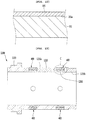
- FIG. 3 is an exploded perspective view of the compressor main body accommodated in the shell of the linear compressor according to the first embodiment
- FIG. 4 is a cross-sectional view taken along line IV-IV' of FIG. 1
- FIG. 5 is a cross-sectional view of a frame and a cylinder according to the first embodiment.
- the linear compressor 10 includes a cylinder 120 provided in the shell 101, a piston 130 that linearly reciprocates within the cylinder 120, and a motor assembly 140 that functions as a linear motor for applying driving force to the piston 130.
- the piston 130 may linearly reciprocate in the axial direction.
- the linear compressor 10 further include a suction muffler 150 coupled to the piston 130 to reduce a noise generated from the refrigerant suctioned through the suction pipe 104.
- the refrigerant suctioned through the suction pipe 104 flows into the piston 130 via the suction muffler 150. For example, while the refrigerant passes through the suction muffler 150, the flow noise of the refrigerant may be reduced.
- the suction muffler 150 includes a plurality of mufflers 151, 152, and 153.
- the plurality of mufflers 151, 152, and 153 include a first muffler 151, a second muffler 152, and a third muffler 153, which are coupled to each other.
- the first muffler 151 is disposed within the piston 130, and the second muffler 152 is coupled to a rear side of the first muffler 151. Also, the third muffler 153 accommodates the second muffler 152 therein and extends to a rear side of the first muffler 151. In view of a flow direction of the refrigerant, the refrigerant suctioned through the suction pipe 104 may successively pass through the third muffler 153, the second muffler 152, and the first muffler 151. In this process, the flow noise of the refrigerant may be reduced.
- the suction muffler 150 further includes a muffler filter 155.
- the muffler filter 155 may be disposed on an interface on which the first muffler 151 and the second muffler 152 are coupled to each other.
- the muffler filter 155 may have a circular shape, and an outer circumferential portion of the muffler filter 155 may be supported between the first and second mufflers 151 and 152.
- the "axial direction” may be understood as a direction in which the piston 130 reciprocates, i.e., the horizontal direction in FIG. 4 .
- a direction from the suction pipe 104 toward a compression space P i.e., a direction in which the refrigerant flows may be defined as a "front direction”
- a direction opposite to the front direction may be defined as a “rear direction”.
- the "radial direction” may be understood as a direction that is perpendicular to the direction in which the piston 130 reciprocates, i.e., the vertical direction in FIG. 4 .
- the piston 130 includes a piston body 131 having an approximately cylindrical shape and a piston flange 132 extending from the piston body 131 in the radial direction.
- the piston body 131 may reciprocate inside the cylinder 120, and the piston flange 132 may reciprocate outside the cylinder 120.
- the cylinder 120 includes a cylinder body 121 extending in the axial direction and a cylinder flange 122 disposed outside a front portion of the cylinder body 121. Also, the cylinder 120 is configured to accommodate at least a portion of the first muffler 151 and at least a portion of the piston body 131.
- the cylinder body 121 includes a gas inflow part (see reference numeral 126 of FIG. 6 ) into which at least a portion of the refrigerant discharged through a discharge valve 161 that will be described later is introduced.
- the gas inflow part 126 may be recessed inward from an outer circumferential surface of the cylinder body 121 in the radial direction.
- the gas inflow part 126 may be provided in plurality.
- the plurality of gas inflow parts 126 may be disposed to be spaced apart from each other along the outer circumferential surface of the cylinder body 121 with respect to a central axis in the axial direction.
- a cylinder filter 200 filtering foreign substances or oil components contained in the refrigerant gas is provided in the gas inflow part 126.
- the cylinder filter 200 includes a plurality of laminated filters. Also, a flow rate of the refrigerant passing through the cylinder filter 200 may be adjusted through the nozzle provided in the cylinder body 121 so that the refrigerant serves as a gas bearing between the piston 130 and the cylinder 120.
- the cylinder 120 has a compression space P in which the refrigerant is compressed by the piston 130. Also, a suction hole 133 through which the refrigerant is introduced into the compression space P is defined in a front surface of the piston body 131, and a suction valve 135 for selectively opening the suction hole 133 is disposed on a front side of the suction hole 133.
- a coupling hole 136a to which a predetermined coupling member 136 is coupled is defined in a front surface of the piston body 131.
- the coupling hole 136a may be defined in a center of the front surface of the piston body 131, and a plurality of suction holes 133 are defined to surround the coupling hole 136a.
- the coupling member 136 passes through the suction valve 135 and is coupled to the coupling hole 136a to fix the suction valve 135 to the front surface of the piston body 131.
- a discharge cover 160 defining a discharge space 160a for the refrigerant discharged from the compression space P and a discharge valve assembly 161 and 163 coupled to the discharge cover 160 to selectively discharge the refrigerant compressed in the compression space P are provided at a front side of the compression space P.
- the discharge space 160a includes a plurality of space parts that are partitioned by inner walls of the discharge cover 160. The plurality of space parts are disposed in the front and rear direction to communicate with each other.
- the discharge valve assemblies 161 and 163 include a discharge valve 161 that is opened when the pressure of the compression space P is above a discharge pressure to introduce the refrigerant into the discharge space 160a of the discharge cover 160 and a spring assembly 163 disposed between the discharge valve 161 and the discharge cover 160 to provide elastic force in the axial direction.
- the spring assembly 163 includes a valve spring 163a and a spring support part 163b for supporting the valve spring 163a to the discharge cover 160.
- the valve spring 163a may include a plate spring.
- the spring support part 163b may be integrally injection-molded to the valve spring 163a through an injection-molding process.
- the discharge valve 161 is coupled to the valve spring 163a, and a rear portion or a rear surface of the discharge valve 161 is disposed to be supported on the front surface of the cylinder 120.
- the compression space may be maintained in the sealed state.
- the compression space P may be opened to allow the refrigerant in the compression space P to be discharged.
- the compression space P may be understood as a space defined between the suction valve 135 and the discharge valve 161.
- the suction valve 135 may be disposed on one side of the compression space P
- the discharge valve 161 may be disposed on the other side of the compression space P, i.e., an opposite side of the suction valve 135.
- the suction valve 135 may be opened to suction the refrigerant into the compression space P.
- the suction valve 135 may compress the refrigerant of the compression space P in a state in which the suction valve 135 is closed.
- valve spring 163a when the pressure of the compression space P is above the discharge pressure, the valve spring 163a may be deformed forward to open the discharge valve 161.
- the refrigerant may be discharged from the compression space P into the discharge space 160a.
- the valve spring 163a When the discharge of the refrigerant is completed, the valve spring 163a may provide restoring force to the discharge valve 161 to close the discharge valve 161.
- the linear compressor 10 further includes a cover pipe 162a coupled to the discharge cover 160 to discharge the refrigerant flowing through the discharge space 160a of the discharge cover 160.
- the cover pipe 162a may be made of a metal material.
- the linear compressor 10 further includes a loop pipe 162b coupled to the cover pipe 162a to transfer the refrigerant flowing through the cover pipe 162a to the discharge pipe 105.
- the loop pipe 162a may have one side of the loop pipe 162b coupled to the cover pipe 162a and the other side coupled to the discharge pipe 105.
- the loop pipe 162b may be made of a flexible material and have a relatively long length. Also, the loop pipe 162b may roundly extend from the cover pipe 162a along the inner circumferential surface of the shell 101 and be coupled to the discharge pipe 105. For example, the loop pipe 162b may have a wound shape.
- the linear compressor 10 further includes a frame 110.
- the frame 110 is understood as a component for fixing the cylinder 120.
- the cylinder 120 may be press-fitted into the frame 110.
- each of the cylinder 120 and the frame 110 may be made of aluminum or an aluminum alloy material.
- the frame 110 includes a frame body 111 having an approximately cylindrical shape and a frame flange 112 extending from the frame body 111 in the radial direction.
- the frame body 111 is disposed to surround the cylinder 120. That is, the cylinder 120 may be disposed to be accommodated into the frame 111. Also, the frame flange 112 may be coupled to the discharge cover 160.
- a gas hole 114 through which at least a portion of the refrigerant discharged through the discharge valve 161 flows to the gas inflow part 126 is defined in the frame 110.
- the gas hole 114 communicates with the frame flange 112 and the frame body 111.
- a filter assembly 300 for filtering the foreign substances contained in the refrigerant to be introduced into the gas hole 114 is disposed on the frame flange 112.
- the filter assembly 300 may be installed to be press-fitted into an inner space defined in the frame flange 112.
- the motor assembly 140 includes an outer stator 141, an inner stator 148 disposed to be spaced inward from the outer stator 141, and a magnet 146 disposed in a space between the outer stator 141 and the inner stator 148.
- the magnet 146 may linearly reciprocate by a mutual electromagnetic force between the outer stator 141 and the inner stator 148. Also, the magnet 146 may be provided as a single magnet having one polarity or be provided by coupling a plurality of magnets having three polarities to each other.
- the inner stator 148 is fixed to an outer circumference of the frame body 111. Also, in the inner stator 148, the plurality of laminations are laminated outside the frame 111 in the radial direction.
- the outer stator 141 includes coil winding bodies 141b, 141c, and 141d and a stator core 141a.
- the coil winding bodies 141b, 141c, and 141d include a bobbin 141b and a coil 141c wound in a circumferential direction of the bobbin 141b.
- the coil winding bodies 141b, 141c, and 141d further include a terminal part 141d that guides a power line connected to the coil 141c so that the power line is led out or exposed to the outside of the outer stator 141.
- the terminal part 141d extends to pass through the frame flange 112.
- the stator core 141a includes a plurality of core blocks in which a plurality of laminations are laminated in a circumferential direction.
- the plurality of core blocks may be disposed to surround at least a portion of the coil winding bodies 141b and 141c.
- a stator cover 149 may be disposed on one side of the outer stator 141.
- the outer stator 141 may have one side supported by the frame flange 112 and the other side supported by the stator cover 149.
- the frame flange 112, the outer stator 141, and the stator cover 149 are sequentially disposed in the axial direction.
- the linear compressor 10 further includes a cover coupling member 149a for coupling the stator cover 149 to the frame flange 112.
- the cover coupling member 149a may pass through the stator cover 149 to extend forward to the frame 112 and then be coupled to the frame flange 112.
- the linear compressor 10 further includes a rear cover 170 coupled to the stator cover 149 to extend backward and supported by the second support device 185.
- the rear cover 170 includes three support legs, and the three support legs may be coupled to a rear surface of the stator cover 149.
- a spacer 181 may be disposed between the three support legs and the rear surface of the stator cover 149.
- a distance from the stator cover 149 to a rear end of the rear cover 170 may be determined by adjusting a thickness of the spacer 181.
- the linear compressor 10 further includes an inflow guide part 156 coupled to the rear cover 170 to guide an inflow of the refrigerant into the suction muffler 150. At least a portion of the inflow guide part 156 may be inserted into the suction muffler 150.
- the linear compressor 10 further includes a plurality of resonant springs 176a and 176b that are adjusted in natural frequency to allow the piston 130 to perform a resonant motion.
- the driving part that reciprocates within the linear compressor 10 may stably move by the action of the plurality of resonant springs 176a and 176b to reduce the vibration or noise due to the movement of the driving part.
- the linear compressor 10 further includes a first support device 165 coupled to the discharge cover 160 to support one side of the main body of the compressor 10.
- the first support device 165 may be disposed adjacent to the second shell cover 103 to elastically support the main body of the compressor 10.
- the first support device 165 includes a first support spring 166.
- the first support spring 166 may be coupled to the spring coupling part 101a.
- the linear compressor 10 further includes a second support device 185 coupled to the rear cover 170 to support the other side of the main body of the compressor 10.
- the second support device 185 may be coupled to the first shell cover 102 to elastically support the main body of the compressor 10.
- the second support device 185 includes a second support spring 186.
- the second support spring 186 may be coupled to the cover support part 102a.
- the linear compressor 10 includes the frame 110 and a plurality of sealing members for increasing coupling force between the peripheral components around the frame 110.
- Each of the plurality of sealing members may have a ring shape.
- the plurality of sealing members include a first sealing member 127 disposed at a portion at which the frame 110 and the discharge cover 160 are coupled to each other. Also, the plurality of sealing members further include second and third sealing members 128 and 129a provided to portions at which the frame 110 and the cylinder 120 are coupled to each other and a fourth sealing member 129b provided at a portion at which the frame 110 and the inner stator 148 are coupled to each other.
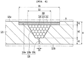
- FIG. 6 is an enlarged view illustrating a portion "A" of FIG. 5 .
- the linear compressor 10 further includes a cylinder filter coupled to the cylinder 120.
- the cylinder 120 includes a cylinder body 121 and a cylinder flange 122 disposed outside the front of the cylinder body 121.
- the cylinder body 121 may have a hollow cylindrical shape that lengthily extends in a horizontal direction or an axial direction. Also, the piston 130 is disposed in the cylinder body 121, and the frame 110 is disposed outside the cylinder body 121.
- the gas inflow part 126 recessed inward from the outer circumferential surface 121a of the cylinder body 121 in the radial direction is provided in the cylinder 120. Also, a cylinder filter 200 that will be described later is disposed on the gas inflow part 126.
- the gas inflow part 126 is a space into which at least a portion of the refrigerant discharged through the discharge valve 161 is introduced into the cylinder body 121.
- the gas inflow part 126 may be continuously provided along a circumference of the cylinder body 121. That is, the gas inflow part 126 may be recessed inward along the circumference of the cylinder body 121 in the radial direction.
- the gas inflow part 126 may have a circular band shape along the outer circumferential surface 121a of the cylinder body 121 with respect to a central axis thereof in the axial direction.
- the gas inflow part 126 may be provided in plurality.
- the plurality of gas inflow parts 126 may be disposed to be spaced apart from the cylinder body 121 in the axial direction.
- the gas inflow part 126 includes a first recess part 126a recessed by a predetermined depth H inward along a circumference of the outer circumferential surface 121a of the cylinder body 121 in the radial direction, a second recess part 126b further recessed by a predetermined depth H2 inward from the first recess part 126a in the radial direction, and a nozzle 126c further recessed by a predetermined depth H3 inward from the second recess part 126b in the radial direction.
- the first recess part 126a, the second recess part 126b, and the nozzle 126 may communicate with each other.
- the nozzle 126c may pass from the inside of the second recess part 126b up to the inner circumferential surface 121b of the cylinder body 121.
- the refrigerant gas introduced from the first recess part 126a may pass through the second recess part 126b and then move to the inside of the cylinder 120 through the nozzle 126c.
- the first recess part 126a may be understood as a space in which a first filter that will be described later is installed.
- the first recess part 126a may be recessed along the outer circumference of the cylinder body 121 to have a relatively large width D1.
- the first recess part 126a may have a circular band shape along the outer circumferential surface 121a of the cylinder body 121 with respect to a central axis thereof in the axial direction.
- the second recess part 126b may be understood as a space in which a second filter that will be described later is installed.
- the second recess part 126b may be further recessed inward from a bottom surface of the first recess part 126a in the radial direction.
- the second recess part 126b may be recessed along a circumference of the first recess part 126a.
- the second recess part 126b may have a width D2 less than that D1 of the first recess part 126a.
- the second recess part 126b may have an area that is gradually narrowed inward in the radial direction.
- the second recess part 126b may be recessed in a circular shape along a central point of the circumference of the first recess part 126a.
- centers of the first filter and the second filter may match each other.
- the nozzle 126c may be understood as a passage through which the refrigerant gas passing through the first filter and the second filter is introduced into the cylinder 120.
- the nozzle 126c may pass from a bottom surface of the second recess part 126b up to the inner circumferential surface 121b of the cylinder body 121.
- the nozzle 126c may have a width or diameter D3 that is relatively less than that of the second recess part 126b.
- the nozzle 126c may have a width or diameter of about 20 ⁇ m to about 40 ⁇ m.
- the nozzle 126c may be surrounded in a circular shape along the circumference of the bottom surface of the second recess part 126b.
- the nozzle 126c may have a circular shape along a central point of the bottom surface of the second recess part 126b.
- centers of the second filter and the nozzle 126c may match each other.
- a length H of the cylinder body 121 in a thickness direction may be defined as the sum of the recessed depths HI, H2, and H3 of the first recess part 126a, the second recess part 126b, and the nozzle 126c.
- the recessed depth H1 of the first recess part 126a may be less than that H2 of the second recess part 126b.
- the recessed depth H2 of the second recess part 126b may be greater than that H3 of the nozzle 126c.
- a ratio of each of the recessed depths HI, H2, and H3 to the length H of the cylinder body 121 in the thickness direction may be designed at a ratio of 0.16:0.44:0.4.
- the cylinder filter 200 may include a first filter 210 and a second filter 220 installed at an outlet-side of the first filter 210.
- the first filter 210 may be made of a metal material and seated on the first recess part 126a.
- the first filter 210 is disposed to be press-fitted into the first recess part 126a.
- the first filter 210 may include a metal fiber filter.
- the first filter 210 may be made of stainless steel.
- the first filter 210 may have a predetermined magnetic property and be prevented from being rusted.
- the first filter 210 may be provided into a mesh type having a plurality of filter holes (not shown).
- the filter hole may be designed to be a size of about 3 ⁇ m or less.
- the first filter 210 may be made of a porous metal material.
- the filter performance of the first filter 210 may be deteriorated even though a pressure and temperature are sharply changed for a long time.
- the second filter 220 includes a PET filter.
- the PET filter may be configured to adsorb fine particles and oil components contained in the refrigerant.
- the second filter 220 may include polyethylene phthalate (PET) and polytetrafluoroethylene (PTFE) membranes.
- a surface of the first filter 210 may be oil-repellent coated.
- a surface (top surface) corresponding to an inlet-side of the first filter 210 may be oil-repellent coated to reduce a surface area of oil disposed on an inlet surface of the first filter 210. That is, the reason in which the surface of the first filter 210 is oil-repellent coated is for preventing the oil from being spread by increasing surface tension of the oil. When the oil is not relatively spread, an occurrence of a phenomenon in which a filter hole defined in the first filter 210 is blocked by the oil may be reduced.
- the first filter 210 may be oil-repellent coated by using an oil-repellent agent.
- an oil-repellent coating layer 215 may be provided on an outer surface of the first filter 210, and thus, the surface area of the oil may be reduced by the oil-repellent coating layer 215.
- the cylinder filter 200 may have a structure in which the oil-repellent coating layer 215, the first filter 210, and the second filter 220 are sequentially laminated.
- the surface area of the oil may be reduced by the oil-repellent coating layer 215. Therefore, the oil contained in the refrigerant may be filtered by the oil-repellent coating layer 215 to prevent the oil from being permeated into the filter.
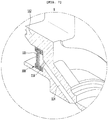
- FIG. 7 is an enlarged view illustrating a portion "B" of FIG. 5
- FIG. 8 is a view illustrating a filter assembly according to the first embodiment
- FIG. 9 is a cross-sectional view taken along line II-II' of FIG. 8
- FIG. 10 is a view illustrating a discharge filter of the filter assembly according to the first embodiment.
- the linear compressor 10 further includes a filter assembly 300 coupled to the frame 110.
- a filter groove 115 that is recessed backward from a front surface of the frame flange 112 is defined in the frame flange 112.
- the filter groove 115 may have a cylindrical shape.
- the filter assembly 300 is disposed inside the filter groove 115.
- the filter assembly 300 may be press-fitted to be fixed to the filter groove 115.
- the linear compressor 10 may further include a filter sealing member 118 installed at the rear of the filter assembly 30, i.e., an outlet-side of the filter assembly 30.
- the filter sealing member 118 may have an approximately ring shape.
- the filter sealing member 118 may be placed on the filter groove 117.
- the filter sealing member 118 may be press-fitted into the filter groove 117.
- coupling force of the filter assembly 300 may increase by the filter sealing member 118.
- foreign substances existing in the shell 101 for example, oil or fine particles may be prevented from being permeated into the refrigerant passing through the filter assembly 300 by the filter sealing member 118.
- the filter assembly 300 includes a filter frame 310 having opened front and rear portions.
- a refrigerant inlet part 312 through which the refrigerant existing in the filter groove 115 is introduced into the filter frame 310 may be provided in the opened front portion of the filter frame 310. Also, a refrigerant discharge part 314 through which the refrigerant passing through the filter assembly 300 is discharged to the outside of the filter frame 310 is provided in the opened rear portion of the filter frame 310.
- the filter frame 310 may have a cylindrical case shape of which both sides are opened by the refrigerant inlet part 312 and the refrigerant discharge part 314.
- the filter frame 310 may be made of a brass material.
- the filter frame 310 includes a first frame 310a providing the refrigerant inlet part 312 and extending from the refrigerant inlet part 312 to the outside in the radial direction, a second frame 310b extending backward from the first frame 310a, and a third frame 310c extending inward from the second frame 310b in the radial direction to provide the refrigerant discharge part 314.
- Each of the first and third frames 310a and 310c may have an approximately ring shape. Also, a rear surface of the third frame 310c may be rounded and configured to press the filter sealing member 118.
- the filter assembly 300 further includes a discharge filter 330 provided in the filter frame 310 and filter support members 320 and 340 supporting the discharge filter 330.
- the discharge filter 330 includes a filter having lipophilicity.
- the discharge filter 330 may be made of a PET material having lipophilicity.
- oil contained in the refrigerant introduced into the filter assembly 300 may be filtered by the discharge filter 330 and thus may not pass through the filter assembly 300.
- At least one or more surfaces of the discharge filter 330 may be oil-repellent coated.
- the reason in which the surface of the discharge filter 330 is oil-repellent coated is for preventing the oil from being spread by increasing surface tension of the oil. When the oil is not relatively spread, an occurrence of a phenomenon in which a filter hole defined in the discharge filter 330 is blocked by the oil may be reduced.
- one surface of a front surface 330a and a rear surface 330b of the discharge filter 330 may be oil-repellent coated.
- the front surface 330a and the rear surface 330b of the discharge filter 330 may be oil-repellent coated by using the oil-repellent agent.
- an oil-repellent coating layer 332 may be disposed on the front surface 330a of the discharge filter 330.
- an oil-repellent coating layer 334 may be disposed on the rear surface 330b of the discharge filter 330.
- the oil-repellent coating layer is provided on the front surface 330a or the rear surface 330b of the discharge filter 330, the oil contained in the refrigerant may not pass through the discharge filter 330.
- the oil or foreign substances contained in the refrigerant gas may be previously filtered before the refrigerant gas is introduced into the cylinder nozzle to effectively prevent the nozzle from being blocked.
- the filter support members 320 and 340 include a first support member 320 disposed at the inlet-side of the discharge filter 330 to support the discharge filter 330 and a second support member 340 disposed at the outlet-side of the discharge filter 330 to support the discharge filter 330.
- the first support member 320 or the second support member 340 may include a fine metal mesh.
- first support member 320 may be supported by the first frame 310a, and the other side of the first support member 320 may support the discharge filter 330.
- second support member 340 may be supported by the third frame 310c, and the other side of the second support member 340 may support the discharge filter 330.
- the discharge filter 330 may be installed between the first and second support members 320 and 340 and thus be stably supported.
- first support member 320 may be supported by the first frame 310a, and the other side of the first support member 320 may support the oil-repellent coating layer 332 provided on the front surface 330a of the discharge filter 330.
- second support member 340 may be supported by the third frame 310c, and the other side of the second support member 320 may support the oil-repellent coating layer 334 provided on the rear surface 330b of the discharge filter 330.
- the discharge filter 330 may be firmly fixed due to the above-described configuration.
- the oil contained in the refrigerant introduced into the refrigerant inlet part 312 of the filter frame 310 may not pass through the discharge filter 330 to prevent the nozzle provided in the cylinder from being blocked.
- FIG. 11 is a cross-sectional view of a filter assembly according to a second embodiment
- FIG. 12 is a view illustrating a discharge filter of the filter assembly according to the second embodiment.
- the current embodiment is the same as the first embodiment except for a structure of a filter assembly. Thus, only characterized parts of the current embodiment will be principally described below, and descriptions of the same part as that of the first embodiment will be quoted from the first embodiment.
- a filter assembly 300 includes a filter frame 310 having opened front and rear portions.
- a refrigerant inlet part 312 through which a refrigerant existing in a filter groove 115 is introduced into the filter frame 310 may be provided in the opened front portion of the filter frame 310. Also, a refrigerant outlet part 314 through which the refrigerant passing through the filter assembly 300 is discharged to the outside of the filter frame 310 is provided in the opened rear portion of the filter frame 310.
- the filter assembly 300 further includes a discharge filter 330 provided in the filter frame 310 and filter support members 320 and 340 supporting the discharge filter 330.
- the filter support members 320 and 340 have the same as those according to the first embodiment, and thus, their detailed description will be omitted.
- the discharge filter 330 includes a plurality of filters 331 and 333.
- the plurality of filters 331 and 333 include a first filter 331 and a second filter 333 disposed at an outlet-side of the first filter 331.
- the first filter 331 may be a mesh filter made of a metal material. That is, the first filter 331 may include a metal fiber filter having a plurality of filter holes.
- the first filter 331 may be formed of stainless steel.
- the first filter 210 may have a predetermined magnetic property and be prevented from being rusted.
- filter performance of the first filter 331 may be deteriorated even though a pressure and temperature are sharply changed for a long time.
- the second filter 333 includes a filter having lipophilicity.
- the second filter 330 may be made of a PET material having lipophilicity.
- oil contained in the refrigerant introduced into the filter assembly 300 may be filtered by the second filter 333 and thus may not pass through the filter assembly 300.
- At least one or more surfaces of the second filter 333 may be oil-repellent coated. That is, the second filter 333 may be the same as the discharge filter according to the foregoing first embodiment.
- an outer surface of the first filter 331 may also be oil-repellent coated.
- the front surface 331a of the first filter 331 may be oil-repellent coated to reduce a surface area of the oil contained in the refrigerant gas.
- the first filter 331 may be oil-repellent coated by using an oil-repellent agent. That is, an oil-repellent coating layer 335 may be disposed on the front surface 331a of the first filter 331.
- the first filter 331 may be disposed at the rear of the first support member 320
- the second filter 333 may be disposed at the rear of the first filter 331
- the second support member 340 may be disposed at the rear of the second filter 333
- the oil-repellent coating layer 335 may be disposed between the first support member 320 and the first filter 331 to filter the oil contained in the refrigerant by the first filter 331, and thus, the oil may not pass through the filter assembly 300.
- FIG. 13 is a view illustrating a state in which a cylinder filter is provided in a cylinder according to a third embodiment
- FIG. 14 is a view illustrating a configuration of the cylinder according to the third embodiment
- FIG. 15 is an enlarged view of a portion "C" of FIG. 13 .
- a cylinder 1200 according to a third embodiment includes a cylinder body 1210 and a cylinder flange 1220 disposed outside a front portion of the cylinder body 1210.
- the cylinder body 1210 may have a hollow cylindrical shape that lengthily extends in a horizontal direction or an axial direction. Also, the piston 130 is disposed in the cylinder body 1210, and a frame 110 is disposed outside the cylinder body 121.
- the cylinder 1200 includes a gas inflow part 1260 passing through the cylinder body 1210.
- the gas inflow part 1260 may be provided in plurality along a circumference of the cylinder body 1210.
- the gas inflow part 1260 is a space into which at least a portion of the refrigerant discharged through a discharge valve 161 is introduced into the cylinder body 1210.
- the gas inflow part 1260 may pass inward from an outer circumferential surface 1210a of the cylinder body 1210 in the radial direction. That is, the gas inflow part 1260 may be a portion that continuously passes from the outer circumferential surface 1210a of the cylinder body 1210 to an inner circumferential surface 1210b of the cylinder body 1210.
- the gas inflow part 1260 may include a seating groove 1260a that is recessed inward from the outer circumferential surface 1210a of the cylinder body 1210 by a predetermined depth in the radial direction and a through-hole 1260b passing from the seating groove 1260a to the inner circumferential surface 1210b of the cylinder body 1210. That is, the seating groove 1260a may communicate with the through-hole 1260b. However, the seating groove 1260a may have a diameter less than that of the through-hole 1260b.
- the seating groove 1260a provides a space in which a cylinder filter 420 that will be described later is mounted.
- the seating groove 1260a is recessed from the outer circumferential surface 1210a of the cylinder body 1210 by a predetermined depth to define a seating surface on which the cylinder filter 420 is seated.
- the seating groove 1260a may have a cylindrical shape.
- a horizontal cross-section of the seating surface may have a circular shape to support the cylindrical filter 420.
- the through-hole 1260b may be further recessed from the seating groove 1260a by a predetermined depth to extend up to the inner circumferential surface 1210b of the cylinder body 1210. Particularly, the through-hole 1260b passes from a central portion of the seating surface to the inner circumferential surface 1210b of the cylinder body 1210.
- the through-hole 1260b has a diameter less than that of the seating groove 1260a, a seating surface on which the cylinder filter 420 is seated may be provided.
- the through-hole 126b may have a circular shape.
- the refrigerant gas passing through the cylinder filter 420 may be uniformly spread into the space between the piston 130 and the cylinder 1200 through the through-hole 1260b.
- the gas inflow part 1260 may be provided in plurality, which are spaced apart from each other along an outer surface of the cylinder 1200.
- the plurality of gas inflow parts 1260 may be disposed to be spaced apart from each other along the outer circumferential surface 1210a of the cylinder body 1210 with respect to a central axis in the axial direction.
- the plurality of gas inflow parts 1260 may be disposed at a certain interval along the circumference of the cylinder 1200. However, this embodiment is not limited thereto.
- the gas inflow parts 1260 may be variously designed in number and position.
- the linear compressor 10 further include a plate 410 installed on the cylinder 1200.
- the plate 410 may be seated on the seating groove 1260a to cover the through-hole 1260b. Also, the plate 410 may support a cylinder filter 420 that will be described later.
- the plate 410 and the cylinder filter 420 may be called a cylinder filter assembly 400.
- the plate 410 may have a disc shape having a predetermined area. Also, a nozzle 411 for adjusting a flow rate of the refrigerant may be provided in the plate 410.
- the nozzle 411 may be provided to pass through a predetermined point of the plate 410.
- the nozzle 411 may pass through a central point of the top surface of the plate 410 in a downward direction.
- the nozzle 411 may have an area that is gradually narrowed inward in the radial direction.
- an inner end of the nozzle 411 may provide a tip portion.
- the flow rate of the refrigerant gas may be adjusted by the diameter of the nozzle 411.
- a surface (a top surface or a bottom surface) of the plate 410 may be oil-repellent coated.
- the top surface 410a of the plate 410 may be oil-repellent coated to reduce a surface area of oil contained in the refrigerant gas.
- the plate 410 may be oil-repellent coated by using an oil-repellent agent.
- an oil-repellent coating layer 412 may be provided on the top surface of the plate 410, and thus, surface tension of the oil may increase by the oil-repellent coating layer 412.
- the oil may not be spread on the top surface 410a of the plate 410 to prevent the nozzle 411 provided in the plate 410 from being blocked by the oil.
- the linear compressor 10 further include a cylinder filter 420 installed in the cylinder 1200.
- the cylinder filter 420 is seated on the seating groove 1260a to filter the foreign substances or oil contained in the refrigerant gas.
- the cylinder filter 420 is made of a metal material and seated on the plate 410.
- the cylinder filter 420 may be disposed to be press-fitted into the seating groove 1260a.
- the cylinder filter 420 may be made of stainless steel. Also, the cylinder filter 420 may have a magnetic property and be prevented from being rusted. Also, the cylinder filter 420 may be provided into a mesh type having a plurality of filter holes (not shown). For example, the filter hole may be designed to be a size of about 3 ⁇ m or less.
- the cylinder filter 420 may be made of a porous metal material. Thus, filter performance of the cylinder filter 420 may be deteriorated even though a pressure and temperature are sharply changed for a long time.
- a surface (a top surface or a bottom surface) of the cylinder filter 420 may be oil-repellent coated.
- the top surface 420a of the cylinder filter 420 may be oil-repellent coated to reduce a surface area of the oil contained in the refrigerant gas.
- the cylinder filter 420 may be oil-repellent coated by using an oil-repellent agent.
- an oil-repellent coating layer 422 may be provided on the top surface 420a of the cylinder filter 420, and thus, the surface tension of the oil may increase by the oil-repellent coating layer 422.
- the oil may not be spread on the top surface 420a of the cylinder filter 420 to prevent the nozzle hole provided in the cylinder filter 420 from being blocked by the oil.
- the surface (top surface or bottom surface) of the plate 410 or the surface (top surface or bottom surface) of the cylinder filter 420 may be oil-repellent coated, and thus, the oil contained in the refrigerant may be prevented from being introduced into the nozzle 411 provided in the plate 410. That is, if even any one of the plate 410 and the cylinder filter 420 is oil-repellent coated, the oil may be prevented from being introduced into the nozzle 410.
- the linear compressor including the above-described constituents according to the embodiment may have the following effects.
- the nozzle through which the refrigerant gas passes may be provided in the cylinder, and the cylinder filter of which at least one or more surfaces are oil-repellent coated may be provided at the inlet-side of the nozzle to adjust the flow rate of the refrigerant gas that is used as the gas bearing and also filter the foreign substances contained in the refrigerant gas.
- the nozzle through which the refrigerant gas is introduced into the cylinder is minimized in diameter or number, the blocking of the nozzle may be prevented while maintaining the performance of the gas bearing.
- the consumption flow rate of the refrigerant gas is relatively smaller than that of the refrigerant gas according to the related art, the piston supporting force equal to or greater than that according to the related art may be secured.
- the cylinder filter provided at the inlet-side of the cylinder nozzle may be oil-repellent coated to effectively prevent the nozzle from being blocked without changing the structure of the existing compressor, thereby reducing the product price and improving general versatility.
- the cylinder filter may include the plurality of filters made of materials different from each other, and the plurality of filters may be laminated in the flow direction of the refrigerant.
- the oil or foreign substances contained in the refrigerant gas may be effectively filtered.
- the discharge filter that is oil-repellent coated may be provided in the frame through which the refrigerant gas is introduced into the cylinder nozzle to previously filer the oil or foreign substances contained in the refrigerant gas before the refrigerant gas is introduced into the cylinder nozzle, thereby effectively prevent the nozzle from being blocked.
Abstract
Description
- The present invention relates to a linear compressor.
- Generally, a compressor is a mechanical device that receives power from a power generating device such as an electric motor or a turbine to increase pressure by compressing air, refrigerant or various other operating gases, and are used throughout the household appliance or industry.
- Such compressors can be classified into reciprocating compressors, rotary compressors, and scroll compressors.
- Many linear compressors are being developed which can improve the compression efficiency without mechanical loss occurring when the rotary motion of the motor is converted into the linear motion by, particularly, connecting the piston directly to the driving motor which reciprocates linearly and has a simple structure among the reciprocating compressor.
- Generally, the linear compressor is configured to suck and compress the refrigerant while the piston is linearly reciprocated within a cylinder by a linear motor in a closed shell and then discharge the refrigerant.
- (Patent Document 1) Korean Patent Publication No.
10-2018-0039959 (April 19, 2018 - In the linear compressor disclosed in prior art document, a gas bearing in which a refrigerant gas is supplied in a space between a cylinder and a piston to perform a bearing function is disclosed. The refrigerant gas flows to an outer circumferential surface of the piston through a nozzle provided in the cylinder to act as a bearing in the reciprocating piston.
- To improve compression efficiency of the linear compressor, it is necessary to minimize a consumed amount of refrigerant gas used as a gas bearing. To reduce the consumed amount of refrigerant gas, a diameter of the cylinder nozzle and the number of cylinder nozzles have to be reduced. However, if the diameter of the cylinder nozzle decreases, or the number of cylinder nozzles is reduced, the cylinder nozzle may be blocked to greatly affect reliability of the compressor.
- That is, if the diameter of the cylinder nozzle decreases, or the number of cylinder nozzles is reduced, the cylinder nozzle may be blocked by oil or a mixture of the oil and dusts to significantly reduce a function of the gas bearing.
- To solve this limitation, according to the prior art document, a thread made of a polyethylene terephthalate (PET) may be wound around a gas inflow part provided on an outer circumferential surface of the cylinder and thus used as a precipitation filter-type filter member.
- However, in this case, when the filter is exposed for a long time under the operation conditions of the compressor in which a pressure and a temperature rapidly change, the tension of the filer may be reduced to significantly deteriorate the filtering performance as time elapses. When the filtering performance is significantly deteriorated, the blocking of the cylinder nozzle becomes serious due to the oil or the mixture of the oil and the dusts.
- Embodiments provide a linear compressor including a cylinder filter that is capable of filtering foreign substances contained in a refrigerant gas while adjusting a flow rate of the refrigerant gas used as a gas bearing.
- Embodiments also provide a linear compressor which is capable of preventing a nozzle from being blocked while maintaining performance of a gas bearing even though a diameter of the nozzle or the number of nozzles, through which a refrigerant gas is introduced into a cylinder, is reduced.
- Embodiments also provide a linear compressor in which foreign substances contained in a refrigerant gas are previously filtered before the refrigerant gas is introduced into a nozzle provided in the cylinder to prevent the nozzle from being blocked.
- Embodiments also provide a linear compressor in which blocking of a nozzle is effectively prevented through a simple process without changing a structure of an existing compressor.
- In one embodiment, a linear compressor includes: a cylinder configured to define a compression space for a refrigerant; a nozzle which is provided in the cylinder and through which a portion of the refrigerant introduced into the compression space passes; and a cylinder filter installed in the cylinder and disposed at an inlet-side of the nozzle. Here, at least one or more surfaces of the cylinder filter may be oil-repellent coated to filter oil or foreign substances contained in the refrigerant gas by using the filter, thereby preventing the filter from being blocked.
- Particularly, a gas inflow part recessed inward from an outer circumferential surface of the cylinder in a radial direction may be provided in the cylinder, and the nozzle may pass from an inner surface of the gas inflow part to an inner circumferential surface of the cylinder.
- Here, the cylinder filter may include: a first filter installed inside the gas inflow part; and a second filter installed at an outlet-side of the first filter inside the gas inflow part, wherein a surface corresponding to an inlet-side of the first filter may be oil-repellent coated. Thus, the oil or the foreign substances contained in the refrigerant gas may be effectively filtered, and a flow rate of the refrigerant gas may be adjusted.
- Also, the first filter may be disposed to be laminated with the second filter, and an outlet-side of the second filter may be connected to the inlet-side of the nozzle.
- For example, the gas inflow part may include: a first recess part recessed inward from the outer circumferential surface of the cylinder in the radial direction; a second recess part further recessed inward from the first recess part in the radial direction, wherein the first filter is disposed in the first recess part, and the second filter is disposed in the second recess part.
- The first recess part may extend along the outer circumferential surface of the cylinder in a circumferential direction to provide a circular band shape, and the second recess part may be recessed inward from a central point of a bottom surface of the first recess part in the radial direction.
- The first filter may include a metal fiber filter having a plurality of filter holes, and the second filter may include a filter made of a polyethylene terephthalate (PET) material. Thus, the first filter may prevent the second filter from being detached outward from the cylinder.
- On the other hand, a gas inflow part passing from an outer circumferential surface to an inner circumferential surface of the cylinder may be provided in the cylinder, and a plate in which the nozzle is provided may be disposed inside the gas inflow part.
- Particularly, the gas inflow part may include: a seating groove recessed inward from the outer circumferential surface of the cylinder in a radial direction; and a through-hole passing from the seating groove to the inner circumferential surface of the cylinder, wherein the plate may be seated in the seating groove.
- Here, the cylinder filter may be laminated on the plate inside the seating groove, and a surface corresponding to an inlet-side of the cylinder filter may be oil-repellent coated. The cylinder filter may be laminated on the plate inside the seating groove, and a surface corresponding to an outlet-side of the cylinder filter may be oil-repellent coated.
- Alternatively, a portion of the refrigerant discharged from the compression space may pass through the cylinder filter and be introduced into the through-hole of the gas inflow part through the nozzle of the plate.
- Thus, the cylinder filter may include a metal fiber filter having a plurality of filter holes, and the plate may be made of an engineering plastic material.
- Here, the linear compressor may further include: a frame body configured to accommodate the cylinder, the frame body extending in an axial direction; a frame flange extending from the frame body in a radial direction; and a frame extending from the frame flange to the frame body, the frame being provided as a frame connection part having a gas hole therein.
- Also, the linear compressor may further include a filter assembly installed at an inlet-side of the gas hole to filter foreign substances of the refrigerant to be introduced into the gas hole, wherein the filter assembly may be installed in a filter groove in which a front surface of the frame flange is recessed backward.
- For example, the filter assembly may include: a filter bracket including a refrigerant inlet part and a refrigerant outlet part, the filter bracket having an accommodation space therein; a discharge filter disposed inside the filter bracket, the discharge filter having a lipophilic property; a first support member disposed at an inlet-side of the discharge filter inside the filter bracket; and a second support member disposed at an outlet-side of the discharge filter inside the filter bracket.
- Here, a surface corresponding to the inlet-side or outlet-side of the discharge filter may be oil-repellent coated to previously filter the foreign substances contained in the refrigerant gas before the refrigerant gas is introduced into the nozzle provided in the cylinder, thereby preventing the nozzle from being blocked.
- For example, the discharge filter may include a first filter contacting the first support member and a second filter disposed at the outlet-side of the first filter to contact the second support member, and a surface corresponding to the inlet-side or outlet-side of the first filter may be oil-repellent coated.
- The details of one or more embodiments are set forth in the accompanying drawings and the description below. Other features will be apparent from the description and drawings, and from the claims.
-
-
FIG. 1 is a perspective view of a linear compressor according to a first embodiment. -
FIG. 2 is a view illustrating a state in which a shell and a shell cover are separated from each other in the linear compressor ofFIG. 1 . -
FIG. 3 is an exploded perspective view of a compressor main body accommodated in the shell of the linear compressor according to the first embodiment. -
FIG. 4 is a cross-sectional view taken along line IV-IV' ofFIG. 1 . -
FIG. 5 is a cross-sectional view of a frame and a cylinder according to the first embodiment. -
FIG. 6 is an enlarged view illustrating a portion "A" ofFIG. 5 . -
FIG. 7 is an enlarged view illustrating a portion "B" ofFIG. 5 . -
FIG. 8 is a view illustrating a filter assembly according to the first embodiment. -
FIG. 9 is a cross-sectional view taken along line II-II' ofFIG. 8 . -
FIG. 10 is a view illustrating a discharge filter of the filter assembly according to the first embodiment. -
FIG. 11 is a cross-sectional view of a filter assembly according to a second embodiment. -
FIG. 12 is a view illustrating a discharge filter of the filter assembly according to the second embodiment. -
FIG. 13 is a view illustrating a state in which a cylinder filter is provided in a cylinder according to a third embodiment. -
FIG. 14 is a view illustrating a configuration of the cylinder according to the third embodiment. -
FIG. 15 is an enlarged view of a portion "C" ofFIG. 13 . - Reference will now be made in detail to the embodiments of the present disclosure, examples of which are illustrated in the accompanying drawings.
- In the following detailed description of the preferred embodiments, reference is made to the accompanying drawings that form a part hereof, and in which is shown by way of illustration specific preferred embodiments in which the invention may be practiced. These embodiments are described in sufficient detail to enable those skilled in the art to practice the invention, and it is understood that other embodiments may be utilized and that logical structural, mechanical, electrical, and chemical changes may be made without departing from the scope of the invention. To avoid detail not necessary to enable those skilled in the art to practice the invention, the description may omit certain information known to those skilled in the art. The following detailed description is, therefore, not to be taken in a limiting sense.
- Also, in the description of embodiments, terms such as first, second, A, B, (a), (b) or the like may be used herein when describing components of the present invention. Each of these terminologies is not used to define an essence, order or sequence of a corresponding component but used merely to distinguish the corresponding component from other component(s). It should be noted that if it is described in the specification that one component is "connected," "coupled" or "joined" to another component, the former may be directly "connected," "coupled," and "joined" to the latter or "connected", "coupled", and "joined" to the latter via another component.
-
FIG. 1 is a perspective view of a linear compressor according to a first embodiment, andFIG. 2 is a view illustrating a state in which a shell and a shell cover are separated from each other in the linear compressor ofFIG. 1 . - Referring to
FIGS. 1 and2 , alinear compressor 10 according to a first embodiment includes ashell 101 and shell covers 102 and 103 coupled to theshell 101. In a broad sense, each of the shell covers 102 and 103 may be understood as one component of theshell 101. - A
leg 50 may be coupled to a lower portion of theshell 101. Theleg 50 may be coupled to a base of a product in which thelinear compressor 10 is installed. For example, the product may include a refrigerator, and the base may include a machine room base of the refrigerator. For another example, the product may include an outdoor unit of an air conditioner, and the base may include a base of the outdoor unit. - The
shell 101 may have an approximately cylindrical shape and be disposed to lie in a horizontal direction or an axial direction. InFIG. 1 , theshell 101 may extend in the horizontal direction and have a relatively low height in a radial direction. That is, since thelinear compressor 10 has a low height, for example, when For example thelinear compressor 10 is installed in the machine room base of the refrigerator, a machine room may be reduced in height. - A terminal 108 may be installed on an outer surface of the
shell 101. The terminal 108 may be understood as a component for transferring external power to a motor assembly (seereference numeral 140 ofFIG. 3 ) of thelinear compressor 10. Particularly, the terminal 108 may be connected to a lead line of a coil (see reference numeral 141c ofFIG. 3 ). - A
bracket 109 is installed outside theterminal 108. Thebracket 109 may include a plurality of brackets surrounding theterminal 108. Thebracket 109 may protect the terminal 108 against an external impact and the like. - Both sides of the
shell 101 may be opened. The shell covers 102 and 103 may be coupled to both the opened sides of theshell 101. In detail, the shell covers 102 and 103 include afirst shell cover 102 coupled to one opened side of theshell 101 and asecond shell cover 103 coupled to the other opened side of theshell 101. An inner space of theshell 101 may be sealed by the shell covers 102 and 103. - In
FIG. 1 , thefirst shell cover 102 may be disposed at a right portion of thelinear compressor 10, and thesecond shell cover 103 may be disposed at a left portion of thelinear compressor 10. That is to say, the first and second shell covers 102 and 103 may be disposed to face each other. - The
linear compressor 10 further includes a plurality ofpipes shell 101 or the shell covers 102 and 103 to suction, discharge, or inject the refrigerant. - The plurality of
pipes suction pipe 104 through which the refrigerant is suctioned into thelinear compressor 10, adischarge pipe 105 through which the compressed refrigerant is discharged from thelinear compressor 10, and a process pipe through which the refrigerant is supplemented to thelinear compressor 10. - For example, the
suction pipe 104 may be coupled to thefirst shell cover 102. The refrigerant may be suctioned into thelinear compressor 10 through thesuction pipe 104 in an axial direction. - The
discharge pipe 105 may be coupled to an outer circumferential surface of theshell 101. The refrigerant suctioned through thesuction pipe 104 may flow in the axial direction and then be compressed. Also, the compressed refrigerant may be discharged through thedischarge pipe 105. Thedischarge pipe 105 may be disposed at a position that is closer to thesecond shell cover 103 than thefirst shell cover 102. - The
process pipe 106 may be coupled to an outer circumferential surface of theshell 101. A worker may inject the refrigerant into thelinear compressor 10 through theprocess pipe 106. - The
process pipe 106 may be coupled to theshell 101 at a height different from that of thedischarge pipe 105 to avoid interference with thedischarge pipe 105. The height is understood as a distance from theleg 50 in the vertical direction (or the radial direction). Since thedischarge pipe 105 and theprocess pipe 106 are coupled to the outer circumferential surface of theshell 101 at the heights different from each other, work convenience may be improved. - At least a portion of the
second shell cover 103 may be disposed adjacent to the inner circumferential surface of theshell 101, which corresponds to a point to which theprocess pipe 106 is coupled. That is to say, at least a portion of thesecond shell cover 103 may act as flow resistance of the refrigerant injected through theprocess pipe 106. - Thus, in view of a passage for the refrigerant, the passage for the refrigerant introduced through the
process pipe 106 decreases in size by thesecond shell cover 103 when entering into the inner space of theshell 101 and then increases in size again after passing through the inner space of theshell 101. In this process, a pressure of the refrigerant may be reduced to allow the refrigerant to be vaporized. Also, in this process, an oil component contained in the refrigerant may be separated. Thus, the refrigerant from which the oil component is separated may be introduced into a piston 130 (seeFIG. 3 ) to improve compression performance of the refrigerant. The oil component may be understood as working oil existing in a cooling system. - A
cover support part 102a is disposed on an inner surface of thefirst shell cover 102. Asecond support device 185 that will be described later may be coupled to thecover support part 102a. Thecover support part 102a and thesecond support device 185 may be understood as devices for supporting a main body of thelinear compressor 10. Here, the main body of thelinear compressor 10 represents a component provided in theshell 101. For example, the main body may include a driving part that reciprocates forward and backward and a support part supporting the driving part. - The driving part may include components such as the
piston 130, amagnet 146, asupport 137, and amuffler 150, which will be described later. Also, the support part may include components such asresonant springs rear cover 170, astator cover 149, afirst support device 165, and asecond support device 185, which will be described later. - A
stopper 102b may be disposed on the inner surface of thefirst shell cover 102. Thestopper 102b may be understood as a component for preventing the main body of thelinear compressor 10, particularly, themotor assembly 140 from being bumped by theshell 101 and thus damaged due to the vibration or the impact occurring during the transportation of thelinear compressor 10. Thestopper 102b may be disposed adjacent to therear cover 170 that will be described later. Thus, when thelinear compressor 10 is shaken, therear cover 170 may interfere with thestopper 102b to prevent the impact from being transmitted to themotor assembly 140. - A
spring coupling part 101a may be disposed on the inner circumferential surface of theshell 101. For example, thespring coupling part 101a may be disposed at a position that is adjacent to thesecond shell cover 103. Thespring coupling part 101a may be coupled to afirst support spring 166 of thefirst support device 165 that will be described later. Since thespring coupling part 101a and thefirst support device 165 are coupled to each other, the main body of the compressor may be stably supported inside theshell 101. -
FIG. 3 is an exploded perspective view of the compressor main body accommodated in the shell of the linear compressor according to the first embodiment, andFIG. 4 is a cross-sectional view taken along line IV-IV' ofFIG. 1 .FIG. 5 is a cross-sectional view of a frame and a cylinder according to the first embodiment. - Referring to
FIGS. 3 to 5 , thelinear compressor 10 according to an embodiment includes acylinder 120 provided in theshell 101, apiston 130 that linearly reciprocates within thecylinder 120, and amotor assembly 140 that functions as a linear motor for applying driving force to thepiston 130. When themotor assembly 140 is driven, thepiston 130 may linearly reciprocate in the axial direction. - Also, the
linear compressor 10 further include asuction muffler 150 coupled to thepiston 130 to reduce a noise generated from the refrigerant suctioned through thesuction pipe 104. The refrigerant suctioned through thesuction pipe 104 flows into thepiston 130 via thesuction muffler 150. For example, while the refrigerant passes through thesuction muffler 150, the flow noise of the refrigerant may be reduced. - The
suction muffler 150 includes a plurality ofmufflers mufflers first muffler 151, asecond muffler 152, and athird muffler 153, which are coupled to each other. - The
first muffler 151 is disposed within thepiston 130, and thesecond muffler 152 is coupled to a rear side of thefirst muffler 151. Also, thethird muffler 153 accommodates thesecond muffler 152 therein and extends to a rear side of thefirst muffler 151. In view of a flow direction of the refrigerant, the refrigerant suctioned through thesuction pipe 104 may successively pass through thethird muffler 153, thesecond muffler 152, and thefirst muffler 151. In this process, the flow noise of the refrigerant may be reduced. - The
suction muffler 150 further includes amuffler filter 155. Themuffler filter 155 may be disposed on an interface on which thefirst muffler 151 and thesecond muffler 152 are coupled to each other. For example, themuffler filter 155 may have a circular shape, and an outer circumferential portion of themuffler filter 155 may be supported between the first andsecond mufflers - Hereinafter, the direction will be defined.
- The "axial direction" may be understood as a direction in which the
piston 130 reciprocates, i.e., the horizontal direction inFIG. 4 . Also, in the axial direction", a direction from thesuction pipe 104 toward a compression space P, i.e., a direction in which the refrigerant flows may be defined as a "front direction", and a direction opposite to the front direction may be defined as a "rear direction". When thepiston 130 moves forward, the compression space P may be compressed. - On the other hand, the "radial direction" may be understood as a direction that is perpendicular to the direction in which the
piston 130 reciprocates, i.e., the vertical direction inFIG. 4 . - The
piston 130 includes apiston body 131 having an approximately cylindrical shape and apiston flange 132 extending from thepiston body 131 in the radial direction. Thepiston body 131 may reciprocate inside thecylinder 120, and thepiston flange 132 may reciprocate outside thecylinder 120. - The
cylinder 120 includes acylinder body 121 extending in the axial direction and acylinder flange 122 disposed outside a front portion of thecylinder body 121. Also, thecylinder 120 is configured to accommodate at least a portion of thefirst muffler 151 and at least a portion of thepiston body 131. - The
cylinder body 121 includes a gas inflow part (seereference numeral 126 ofFIG. 6 ) into which at least a portion of the refrigerant discharged through adischarge valve 161 that will be described later is introduced. Thegas inflow part 126 may be recessed inward from an outer circumferential surface of thecylinder body 121 in the radial direction. - The
gas inflow part 126 may be provided in plurality. The plurality ofgas inflow parts 126 may be disposed to be spaced apart from each other along the outer circumferential surface of thecylinder body 121 with respect to a central axis in the axial direction. - A
cylinder filter 200 filtering foreign substances or oil components contained in the refrigerant gas is provided in thegas inflow part 126. Thecylinder filter 200 includes a plurality of laminated filters. Also, a flow rate of the refrigerant passing through thecylinder filter 200 may be adjusted through the nozzle provided in thecylinder body 121 so that the refrigerant serves as a gas bearing between thepiston 130 and thecylinder 120. - Also, the
cylinder 120 has a compression space P in which the refrigerant is compressed by thepiston 130. Also, asuction hole 133 through which the refrigerant is introduced into the compression space P is defined in a front surface of thepiston body 131, and asuction valve 135 for selectively opening thesuction hole 133 is disposed on a front side of thesuction hole 133. - Also, a coupling hole 136a to which a
predetermined coupling member 136 is coupled is defined in a front surface of thepiston body 131. In detail, the coupling hole 136a may be defined in a center of the front surface of thepiston body 131, and a plurality of suction holes 133 are defined to surround the coupling hole 136a. Also, thecoupling member 136 passes through thesuction valve 135 and is coupled to the coupling hole 136a to fix thesuction valve 135 to the front surface of thepiston body 131. - A
discharge cover 160 defining adischarge space 160a for the refrigerant discharged from the compression space P and adischarge valve assembly discharge cover 160 to selectively discharge the refrigerant compressed in the compression space P are provided at a front side of the compression space P. Thedischarge space 160a includes a plurality of space parts that are partitioned by inner walls of thedischarge cover 160. The plurality of space parts are disposed in the front and rear direction to communicate with each other. - The
discharge valve assemblies discharge valve 161 that is opened when the pressure of the compression space P is above a discharge pressure to introduce the refrigerant into thedischarge space 160a of thedischarge cover 160 and aspring assembly 163 disposed between thedischarge valve 161 and thedischarge cover 160 to provide elastic force in the axial direction. - The
spring assembly 163 includes avalve spring 163a and aspring support part 163b for supporting thevalve spring 163a to thedischarge cover 160. For example, thevalve spring 163a may include a plate spring. Also, thespring support part 163b may be integrally injection-molded to thevalve spring 163a through an injection-molding process. - The
discharge valve 161 is coupled to thevalve spring 163a, and a rear portion or a rear surface of thedischarge valve 161 is disposed to be supported on the front surface of thecylinder 120. When thedischarge valve 161 is supported on the front surface of thecylinder 120, the compression space may be maintained in the sealed state. When thedischarge valve 161 is spaced apart from the front surface of thecylinder 120, the compression space P may be opened to allow the refrigerant in the compression space P to be discharged. - Thus, the compression space P may be understood as a space defined between the
suction valve 135 and thedischarge valve 161. Also, thesuction valve 135 may be disposed on one side of the compression space P, and thedischarge valve 161 may be disposed on the other side of the compression space P, i.e., an opposite side of thesuction valve 135. - While the
piston 130 linearly reciprocates within thecylinder 120, when the pressure of the compression space P is below the discharge pressure and a suction pressure, thesuction valve 135 may be opened to suction the refrigerant into the compression space P. On the other hand, when the pressure of the compression space P is above the suction pressure, thesuction valve 135 may compress the refrigerant of the compression space P in a state in which thesuction valve 135 is closed. - Also, when the pressure of the compression space P is above the discharge pressure, the
valve spring 163a may be deformed forward to open thedischarge valve 161. Here, the refrigerant may be discharged from the compression space P into thedischarge space 160a. When the discharge of the refrigerant is completed, thevalve spring 163a may provide restoring force to thedischarge valve 161 to close thedischarge valve 161. - The
linear compressor 10 further includes acover pipe 162a coupled to thedischarge cover 160 to discharge the refrigerant flowing through thedischarge space 160a of thedischarge cover 160. For example, thecover pipe 162a may be made of a metal material. - Also, the
linear compressor 10 further includes aloop pipe 162b coupled to thecover pipe 162a to transfer the refrigerant flowing through thecover pipe 162a to thedischarge pipe 105. Theloop pipe 162a may have one side of theloop pipe 162b coupled to thecover pipe 162a and the other side coupled to thedischarge pipe 105. - The
loop pipe 162b may be made of a flexible material and have a relatively long length. Also, theloop pipe 162b may roundly extend from thecover pipe 162a along the inner circumferential surface of theshell 101 and be coupled to thedischarge pipe 105. For example, theloop pipe 162b may have a wound shape. - The
linear compressor 10 further includes aframe 110. Theframe 110 is understood as a component for fixing thecylinder 120. For example, thecylinder 120 may be press-fitted into theframe 110. Also, each of thecylinder 120 and theframe 110 may be made of aluminum or an aluminum alloy material. - The
frame 110 includes aframe body 111 having an approximately cylindrical shape and aframe flange 112 extending from theframe body 111 in the radial direction. Theframe body 111 is disposed to surround thecylinder 120. That is, thecylinder 120 may be disposed to be accommodated into theframe 111. Also, theframe flange 112 may be coupled to thedischarge cover 160. - Also, a
gas hole 114 through which at least a portion of the refrigerant discharged through thedischarge valve 161 flows to thegas inflow part 126 is defined in theframe 110. Thegas hole 114 communicates with theframe flange 112 and theframe body 111. - Also, a
filter assembly 300 for filtering the foreign substances contained in the refrigerant to be introduced into thegas hole 114 is disposed on theframe flange 112. Thefilter assembly 300 may be installed to be press-fitted into an inner space defined in theframe flange 112. - The
motor assembly 140 includes anouter stator 141, aninner stator 148 disposed to be spaced inward from theouter stator 141, and amagnet 146 disposed in a space between theouter stator 141 and theinner stator 148. - The
magnet 146 may linearly reciprocate by a mutual electromagnetic force between theouter stator 141 and theinner stator 148. Also, themagnet 146 may be provided as a single magnet having one polarity or be provided by coupling a plurality of magnets having three polarities to each other. - The
inner stator 148 is fixed to an outer circumference of theframe body 111. Also, in theinner stator 148, the plurality of laminations are laminated outside theframe 111 in the radial direction. - The
outer stator 141 includescoil winding bodies stator core 141a. Thecoil winding bodies bobbin 141b and acoil 141c wound in a circumferential direction of thebobbin 141b. - The
coil winding bodies terminal part 141d that guides a power line connected to thecoil 141c so that the power line is led out or exposed to the outside of theouter stator 141. Theterminal part 141d extends to pass through theframe flange 112. - The
stator core 141a includes a plurality of core blocks in which a plurality of laminations are laminated in a circumferential direction. The plurality of core blocks may be disposed to surround at least a portion of thecoil winding bodies - A
stator cover 149 may be disposed on one side of theouter stator 141. Here, theouter stator 141 may have one side supported by theframe flange 112 and the other side supported by thestator cover 149. In summary, theframe flange 112, theouter stator 141, and thestator cover 149 are sequentially disposed in the axial direction. - Also, the
linear compressor 10 further includes acover coupling member 149a for coupling thestator cover 149 to theframe flange 112. Thecover coupling member 149a may pass through thestator cover 149 to extend forward to theframe 112 and then be coupled to theframe flange 112. - Also, the
linear compressor 10 further includes arear cover 170 coupled to thestator cover 149 to extend backward and supported by thesecond support device 185. - In detail, the
rear cover 170 includes three support legs, and the three support legs may be coupled to a rear surface of thestator cover 149. Aspacer 181 may be disposed between the three support legs and the rear surface of thestator cover 149. A distance from thestator cover 149 to a rear end of therear cover 170 may be determined by adjusting a thickness of thespacer 181. - Also, the
linear compressor 10 further includes aninflow guide part 156 coupled to therear cover 170 to guide an inflow of the refrigerant into thesuction muffler 150. At least a portion of theinflow guide part 156 may be inserted into thesuction muffler 150. - Also, the
linear compressor 10 further includes a plurality ofresonant springs piston 130 to perform a resonant motion. The driving part that reciprocates within thelinear compressor 10 may stably move by the action of the plurality ofresonant springs - Also, the
linear compressor 10 further includes afirst support device 165 coupled to thedischarge cover 160 to support one side of the main body of thecompressor 10. Thefirst support device 165 may be disposed adjacent to thesecond shell cover 103 to elastically support the main body of thecompressor 10. In detail, thefirst support device 165 includes afirst support spring 166. Thefirst support spring 166 may be coupled to thespring coupling part 101a. - Also, the
linear compressor 10 further includes asecond support device 185 coupled to therear cover 170 to support the other side of the main body of thecompressor 10. Thesecond support device 185 may be coupled to thefirst shell cover 102 to elastically support the main body of thecompressor 10. In detail, thesecond support device 185 includes asecond support spring 186. Thesecond support spring 186 may be coupled to thecover support part 102a. - Also, the
linear compressor 10 includes theframe 110 and a plurality of sealing members for increasing coupling force between the peripheral components around theframe 110. Each of the plurality of sealing members may have a ring shape. - In detail, the plurality of sealing members include a
first sealing member 127 disposed at a portion at which theframe 110 and thedischarge cover 160 are coupled to each other. Also, the plurality of sealing members further include second andthird sealing members frame 110 and thecylinder 120 are coupled to each other and afourth sealing member 129b provided at a portion at which theframe 110 and theinner stator 148 are coupled to each other. - Hereinafter, the cylinder filter according to the first embodiment will be described in detail with reference to the accompanying drawings.
-
FIG. 6 is an enlarged view illustrating a portion "A" ofFIG. 5 . - Referring to
FIGS. 5 and6 , thelinear compressor 10 further includes a cylinder filter coupled to thecylinder 120. - The
cylinder 120 includes acylinder body 121 and acylinder flange 122 disposed outside the front of thecylinder body 121. - The
cylinder body 121 may have a hollow cylindrical shape that lengthily extends in a horizontal direction or an axial direction. Also, thepiston 130 is disposed in thecylinder body 121, and theframe 110 is disposed outside thecylinder body 121. - The
gas inflow part 126 recessed inward from the outercircumferential surface 121a of thecylinder body 121 in the radial direction is provided in thecylinder 120. Also, acylinder filter 200 that will be described later is disposed on thegas inflow part 126. Thegas inflow part 126 is a space into which at least a portion of the refrigerant discharged through thedischarge valve 161 is introduced into thecylinder body 121. - The
gas inflow part 126 may be continuously provided along a circumference of thecylinder body 121. That is, thegas inflow part 126 may be recessed inward along the circumference of thecylinder body 121 in the radial direction. Here, thegas inflow part 126 may have a circular band shape along the outercircumferential surface 121a of thecylinder body 121 with respect to a central axis thereof in the axial direction. - The
gas inflow part 126 may be provided in plurality. The plurality ofgas inflow parts 126 may be disposed to be spaced apart from thecylinder body 121 in the axial direction. - In detail, the
gas inflow part 126 includes afirst recess part 126a recessed by a predetermined depth H inward along a circumference of the outercircumferential surface 121a of thecylinder body 121 in the radial direction, asecond recess part 126b further recessed by a predetermined depth H2 inward from thefirst recess part 126a in the radial direction, and anozzle 126c further recessed by a predetermined depth H3 inward from thesecond recess part 126b in the radial direction. - That is, the
first recess part 126a, thesecond recess part 126b, and thenozzle 126 may communicate with each other. Here, thenozzle 126c may pass from the inside of thesecond recess part 126b up to the innercircumferential surface 121b of thecylinder body 121. Thus, the refrigerant gas introduced from thefirst recess part 126a may pass through thesecond recess part 126b and then move to the inside of thecylinder 120 through thenozzle 126c. - The
first recess part 126a may be understood as a space in which a first filter that will be described later is installed. For this, thefirst recess part 126a may be recessed along the outer circumference of thecylinder body 121 to have a relatively large width D1. Thefirst recess part 126a may have a circular band shape along the outercircumferential surface 121a of thecylinder body 121 with respect to a central axis thereof in the axial direction. - The
second recess part 126b may be understood as a space in which a second filter that will be described later is installed. For this, thesecond recess part 126b may be further recessed inward from a bottom surface of thefirst recess part 126a in the radial direction. Thesecond recess part 126b may be recessed along a circumference of thefirst recess part 126a. - Here, the
second recess part 126b may have a width D2 less than that D1 of thefirst recess part 126a. Particularly, thesecond recess part 126b may have an area that is gradually narrowed inward in the radial direction. - Also, the
second recess part 126b may be recessed in a circular shape along a central point of the circumference of thefirst recess part 126a. Thus, centers of the first filter and the second filter may match each other. - The
nozzle 126c may be understood as a passage through which the refrigerant gas passing through the first filter and the second filter is introduced into thecylinder 120. Thenozzle 126c may pass from a bottom surface of thesecond recess part 126b up to the innercircumferential surface 121b of thecylinder body 121. - The
nozzle 126c may have a width or diameter D3 that is relatively less than that of thesecond recess part 126b. For example, thenozzle 126c may have a width or diameter of about 20 µm to about 40 µm. - Also, the
nozzle 126c may be surrounded in a circular shape along the circumference of the bottom surface of thesecond recess part 126b. Here, thenozzle 126c may have a circular shape along a central point of the bottom surface of thesecond recess part 126b. Thus, centers of the second filter and thenozzle 126c may match each other. - A length H of the
cylinder body 121 in a thickness direction may be defined as the sum of the recessed depths HI, H2, and H3 of thefirst recess part 126a, thesecond recess part 126b, and thenozzle 126c. - Here, the recessed depth H1 of the
first recess part 126a may be less than that H2 of thesecond recess part 126b. Also, the recessed depth H2 of thesecond recess part 126b may be greater than that H3 of thenozzle 126c. For example, a ratio of each of the recessed depths HI, H2, and H3 to the length H of thecylinder body 121 in the thickness direction may be designed at a ratio of 0.16:0.44:0.4. - The
cylinder filter 200 may include afirst filter 210 and asecond filter 220 installed at an outlet-side of thefirst filter 210. - The
first filter 210 may be made of a metal material and seated on thefirst recess part 126a. Thefirst filter 210 is disposed to be press-fitted into thefirst recess part 126a. Thefirst filter 210 may include a metal fiber filter. - For example, the
first filter 210 may be made of stainless steel. Thus, thefirst filter 210 may have a predetermined magnetic property and be prevented from being rusted. Also, thefirst filter 210 may be provided into a mesh type having a plurality of filter holes (not shown). For example, the filter hole may be designed to be a size of about 3 µm or less. - That is, the
first filter 210 may be made of a porous metal material. Thus, the filter performance of thefirst filter 210 may be deteriorated even though a pressure and temperature are sharply changed for a long time. - The
second filter 220 includes a PET filter. The PET filter may be configured to adsorb fine particles and oil components contained in the refrigerant. For example, thesecond filter 220 may include polyethylene phthalate (PET) and polytetrafluoroethylene (PTFE) membranes. - A surface of the
first filter 210 may be oil-repellent coated. - In detail, a surface (top surface) corresponding to an inlet-side of the
first filter 210 may be oil-repellent coated to reduce a surface area of oil disposed on an inlet surface of thefirst filter 210. That is, the reason in which the surface of thefirst filter 210 is oil-repellent coated is for preventing the oil from being spread by increasing surface tension of the oil. When the oil is not relatively spread, an occurrence of a phenomenon in which a filter hole defined in thefirst filter 210 is blocked by the oil may be reduced. - Here, the
first filter 210 may be oil-repellent coated by using an oil-repellent agent. Thus, an oil-repellent coating layer 215 may be provided on an outer surface of thefirst filter 210, and thus, the surface area of the oil may be reduced by the oil-repellent coating layer 215. - In summary, the
cylinder filter 200 may have a structure in which the oil-repellent coating layer 215, thefirst filter 210, and thesecond filter 220 are sequentially laminated. Thus, the surface area of the oil may be reduced by the oil-repellent coating layer 215. Therefore, the oil contained in the refrigerant may be filtered by the oil-repellent coating layer 215 to prevent the oil from being permeated into the filter. - Hereinafter, a filter assembly according to the first embodiment will be described in detail with reference to the accompanying drawings.
-
FIG. 7 is an enlarged view illustrating a portion "B" ofFIG. 5 ,FIG. 8 is a view illustrating a filter assembly according to the first embodiment,FIG. 9 is a cross-sectional view taken along line II-II' ofFIG. 8 , andFIG. 10 is a view illustrating a discharge filter of the filter assembly according to the first embodiment. - Referring to
FIGS. 7 and10 , thelinear compressor 10 further includes afilter assembly 300 coupled to theframe 110. - Particularly, a
filter groove 115 that is recessed backward from a front surface of theframe flange 112 is defined in theframe flange 112. Thefilter groove 115 may have a cylindrical shape. - Also, the
filter assembly 300 is disposed inside thefilter groove 115. Thefilter assembly 300 may be press-fitted to be fixed to thefilter groove 115. - Also, the
linear compressor 10 may further include afilter sealing member 118 installed at the rear of the filter assembly 30, i.e., an outlet-side of the filter assembly 30. - The
filter sealing member 118 may have an approximately ring shape. - In detail, the
filter sealing member 118 may be placed on the filter groove 117. When thefilter assembly 300 presses thefilter groove 115, thefilter sealing member 118 may be press-fitted into the filter groove 117. Thus, coupling force of thefilter assembly 300 may increase by thefilter sealing member 118. In addition, foreign substances existing in theshell 101, for example, oil or fine particles may be prevented from being permeated into the refrigerant passing through thefilter assembly 300 by thefilter sealing member 118. - The
filter assembly 300 includes afilter frame 310 having opened front and rear portions. - A
refrigerant inlet part 312 through which the refrigerant existing in thefilter groove 115 is introduced into thefilter frame 310 may be provided in the opened front portion of thefilter frame 310. Also, arefrigerant discharge part 314 through which the refrigerant passing through thefilter assembly 300 is discharged to the outside of thefilter frame 310 is provided in the opened rear portion of thefilter frame 310. - The
filter frame 310 may have a cylindrical case shape of which both sides are opened by therefrigerant inlet part 312 and therefrigerant discharge part 314. For example, thefilter frame 310 may be made of a brass material. - In detail, the
filter frame 310 includes afirst frame 310a providing therefrigerant inlet part 312 and extending from therefrigerant inlet part 312 to the outside in the radial direction, asecond frame 310b extending backward from thefirst frame 310a, and athird frame 310c extending inward from thesecond frame 310b in the radial direction to provide therefrigerant discharge part 314. - Each of the first and
third frames third frame 310c may be rounded and configured to press thefilter sealing member 118. - Also, the
filter assembly 300 further includes adischarge filter 330 provided in thefilter frame 310 and filtersupport members discharge filter 330. - The
discharge filter 330 includes a filter having lipophilicity. - For example, the
discharge filter 330 may be made of a PET material having lipophilicity. Thus, oil contained in the refrigerant introduced into thefilter assembly 300 may be filtered by thedischarge filter 330 and thus may not pass through thefilter assembly 300. - Also, at least one or more surfaces of the
discharge filter 330 may be oil-repellent coated. The reason in which the surface of thedischarge filter 330 is oil-repellent coated is for preventing the oil from being spread by increasing surface tension of the oil. When the oil is not relatively spread, an occurrence of a phenomenon in which a filter hole defined in thedischarge filter 330 is blocked by the oil may be reduced. - In detail, one surface of a
front surface 330a and arear surface 330b of thedischarge filter 330 may be oil-repellent coated. Here, thefront surface 330a and therear surface 330b of thedischarge filter 330 may be oil-repellent coated by using the oil-repellent agent. - That is, an oil-
repellent coating layer 332 may be disposed on thefront surface 330a of thedischarge filter 330. Also, an oil-repellent coating layer 334 may be disposed on therear surface 330b of thedischarge filter 330. Thus, since the oil-repellent coating layer is provided on thefront surface 330a or therear surface 330b of thedischarge filter 330, the oil contained in the refrigerant may not pass through thedischarge filter 330. - Thus, the oil or foreign substances contained in the refrigerant gas may be previously filtered before the refrigerant gas is introduced into the cylinder nozzle to effectively prevent the nozzle from being blocked.
- The
filter support members first support member 320 disposed at the inlet-side of thedischarge filter 330 to support thedischarge filter 330 and asecond support member 340 disposed at the outlet-side of thedischarge filter 330 to support thedischarge filter 330. Thefirst support member 320 or thesecond support member 340 may include a fine metal mesh. - One side of the
first support member 320 may be supported by thefirst frame 310a, and the other side of thefirst support member 320 may support thedischarge filter 330. Also, one side of thesecond support member 340 may be supported by thethird frame 310c, and the other side of thesecond support member 340 may support thedischarge filter 330. Thedischarge filter 330 may be installed between the first andsecond support members - Alternatively, one side of the
first support member 320 may be supported by thefirst frame 310a, and the other side of thefirst support member 320 may support the oil-repellent coating layer 332 provided on thefront surface 330a of thedischarge filter 330. Also, one side of thesecond support member 340 may be supported by thethird frame 310c, and the other side of thesecond support member 320 may support the oil-repellent coating layer 334 provided on therear surface 330b of thedischarge filter 330. - Thus, the
discharge filter 330 may be firmly fixed due to the above-described configuration. In addition, the oil contained in the refrigerant introduced into therefrigerant inlet part 312 of thefilter frame 310 may not pass through thedischarge filter 330 to prevent the nozzle provided in the cylinder from being blocked. -
FIG. 11 is a cross-sectional view of a filter assembly according to a second embodiment, andFIG. 12 is a view illustrating a discharge filter of the filter assembly according to the second embodiment. - The current embodiment is the same as the first embodiment except for a structure of a filter assembly. Thus, only characterized parts of the current embodiment will be principally described below, and descriptions of the same part as that of the first embodiment will be quoted from the first embodiment.
- Referring to
FIGS. 11 and12 , afilter assembly 300 according to a second embodiment includes afilter frame 310 having opened front and rear portions. - A
refrigerant inlet part 312 through which a refrigerant existing in afilter groove 115 is introduced into thefilter frame 310 may be provided in the opened front portion of thefilter frame 310. Also, arefrigerant outlet part 314 through which the refrigerant passing through thefilter assembly 300 is discharged to the outside of thefilter frame 310 is provided in the opened rear portion of thefilter frame 310. - Also, the
filter assembly 300 further includes adischarge filter 330 provided in thefilter frame 310 and filtersupport members discharge filter 330. Thefilter support members - Particularly, in this embodiment, the
discharge filter 330 includes a plurality offilters filters first filter 331 and asecond filter 333 disposed at an outlet-side of thefirst filter 331. - The
first filter 331 may be a mesh filter made of a metal material. That is, thefirst filter 331 may include a metal fiber filter having a plurality of filter holes. - For example, the
first filter 331 may be formed of stainless steel. Thus, thefirst filter 210 may have a predetermined magnetic property and be prevented from being rusted. Thus, filter performance of thefirst filter 331 may be deteriorated even though a pressure and temperature are sharply changed for a long time. - The
second filter 333 includes a filter having lipophilicity. - For example, the
second filter 330 may be made of a PET material having lipophilicity. Thus, oil contained in the refrigerant introduced into thefilter assembly 300 may be filtered by thesecond filter 333 and thus may not pass through thefilter assembly 300. - Also, at least one or more surfaces of the
second filter 333 may be oil-repellent coated. That is, thesecond filter 333 may be the same as the discharge filter according to the foregoing first embodiment. - In this embodiment, an outer surface of the
first filter 331 may also be oil-repellent coated. - In detail, the
front surface 331a of thefirst filter 331 may be oil-repellent coated to reduce a surface area of the oil contained in the refrigerant gas. Here, thefirst filter 331 may be oil-repellent coated by using an oil-repellent agent. That is, an oil-repellent coating layer 335 may be disposed on thefront surface 331a of thefirst filter 331. - In summary, the
first filter 331 may be disposed at the rear of thefirst support member 320, and thesecond filter 333 may be disposed at the rear of thefirst filter 331. Also, thesecond support member 340 may be disposed at the rear of thesecond filter 333. Also, the oil-repellent coating layer 335 may be disposed between thefirst support member 320 and thefirst filter 331 to filter the oil contained in the refrigerant by thefirst filter 331, and thus, the oil may not pass through thefilter assembly 300. -
FIG. 13 is a view illustrating a state in which a cylinder filter is provided in a cylinder according to a third embodiment,FIG. 14 is a view illustrating a configuration of the cylinder according to the third embodiment, andFIG. 15 is an enlarged view of a portion "C" ofFIG. 13 . - Referring to
FIGS. 13 to 15 , acylinder 1200 according to a third embodiment includes acylinder body 1210 and acylinder flange 1220 disposed outside a front portion of thecylinder body 1210. - The
cylinder body 1210 may have a hollow cylindrical shape that lengthily extends in a horizontal direction or an axial direction. Also, thepiston 130 is disposed in thecylinder body 1210, and aframe 110 is disposed outside thecylinder body 121. - The
cylinder 1200 includes agas inflow part 1260 passing through thecylinder body 1210. Thegas inflow part 1260 may be provided in plurality along a circumference of thecylinder body 1210. Thegas inflow part 1260 is a space into which at least a portion of the refrigerant discharged through adischarge valve 161 is introduced into thecylinder body 1210. - The
gas inflow part 1260 may pass inward from an outercircumferential surface 1210a of thecylinder body 1210 in the radial direction. That is, thegas inflow part 1260 may be a portion that continuously passes from the outercircumferential surface 1210a of thecylinder body 1210 to an innercircumferential surface 1210b of thecylinder body 1210. - In detail, the
gas inflow part 1260 may include aseating groove 1260a that is recessed inward from the outercircumferential surface 1210a of thecylinder body 1210 by a predetermined depth in the radial direction and a through-hole 1260b passing from theseating groove 1260a to the innercircumferential surface 1210b of thecylinder body 1210. That is, theseating groove 1260a may communicate with the through-hole 1260b. However, theseating groove 1260a may have a diameter less than that of the through-hole 1260b. - The
seating groove 1260a provides a space in which acylinder filter 420 that will be described later is mounted. For this, theseating groove 1260a is recessed from the outercircumferential surface 1210a of thecylinder body 1210 by a predetermined depth to define a seating surface on which thecylinder filter 420 is seated. - For example, the
seating groove 1260a may have a cylindrical shape. In this case, a horizontal cross-section of the seating surface may have a circular shape to support thecylindrical filter 420. - The through-
hole 1260b may be further recessed from theseating groove 1260a by a predetermined depth to extend up to the innercircumferential surface 1210b of thecylinder body 1210. Particularly, the through-hole 1260b passes from a central portion of the seating surface to the innercircumferential surface 1210b of thecylinder body 1210. - Here, since the through-
hole 1260b has a diameter less than that of theseating groove 1260a, a seating surface on which thecylinder filter 420 is seated may be provided. - The through-
hole 126b may have a circular shape. Thus, the refrigerant gas passing through thecylinder filter 420 may be uniformly spread into the space between thepiston 130 and thecylinder 1200 through the through-hole 1260b. - The
gas inflow part 1260 may be provided in plurality, which are spaced apart from each other along an outer surface of thecylinder 1200. For example, the plurality ofgas inflow parts 1260 may be disposed to be spaced apart from each other along the outercircumferential surface 1210a of thecylinder body 1210 with respect to a central axis in the axial direction. - The plurality of
gas inflow parts 1260 may be disposed at a certain interval along the circumference of thecylinder 1200. However, this embodiment is not limited thereto. For example, thegas inflow parts 1260 may be variously designed in number and position. - The
linear compressor 10 further include aplate 410 installed on thecylinder 1200. - The
plate 410 may be seated on theseating groove 1260a to cover the through-hole 1260b. Also, theplate 410 may support acylinder filter 420 that will be described later. - Here, the
plate 410 and thecylinder filter 420 may be called acylinder filter assembly 400. - The
plate 410 may have a disc shape having a predetermined area. Also, anozzle 411 for adjusting a flow rate of the refrigerant may be provided in theplate 410. - The
nozzle 411 may be provided to pass through a predetermined point of theplate 410. Preferably, thenozzle 411 may pass through a central point of the top surface of theplate 410 in a downward direction. - For example, the
nozzle 411 may have an area that is gradually narrowed inward in the radial direction. Thus, an inner end of thenozzle 411 may provide a tip portion. Thus, the flow rate of the refrigerant gas may be adjusted by the diameter of thenozzle 411. - Particularly, a surface (a top surface or a bottom surface) of the
plate 410 may be oil-repellent coated. - In detail, the
top surface 410a of theplate 410 may be oil-repellent coated to reduce a surface area of oil contained in the refrigerant gas. Here, theplate 410 may be oil-repellent coated by using an oil-repellent agent. Thus, an oil-repellent coating layer 412 may be provided on the top surface of theplate 410, and thus, surface tension of the oil may increase by the oil-repellent coating layer 412. Thus, the oil may not be spread on thetop surface 410a of theplate 410 to prevent thenozzle 411 provided in theplate 410 from being blocked by the oil. - Also, the
linear compressor 10 further include acylinder filter 420 installed in thecylinder 1200. - The
cylinder filter 420 is seated on theseating groove 1260a to filter the foreign substances or oil contained in the refrigerant gas. Thecylinder filter 420 is made of a metal material and seated on theplate 410. Thecylinder filter 420 may be disposed to be press-fitted into theseating groove 1260a. - For example, the
cylinder filter 420 may be made of stainless steel. Also, thecylinder filter 420 may have a magnetic property and be prevented from being rusted. Also, thecylinder filter 420 may be provided into a mesh type having a plurality of filter holes (not shown). For example, the filter hole may be designed to be a size of about 3 µm or less. - That is, the
cylinder filter 420 may be made of a porous metal material. Thus, filter performance of thecylinder filter 420 may be deteriorated even though a pressure and temperature are sharply changed for a long time. - Particularly, a surface (a top surface or a bottom surface) of the
cylinder filter 420 may be oil-repellent coated. - In detail, the
top surface 420a of thecylinder filter 420 may be oil-repellent coated to reduce a surface area of the oil contained in the refrigerant gas. Here, thecylinder filter 420 may be oil-repellent coated by using an oil-repellent agent. Thus, an oil-repellent coating layer 422 may be provided on thetop surface 420a of thecylinder filter 420, and thus, the surface tension of the oil may increase by the oil-repellent coating layer 422. Thus, the oil may not be spread on thetop surface 420a of thecylinder filter 420 to prevent the nozzle hole provided in thecylinder filter 420 from being blocked by the oil. - In summary, the surface (top surface or bottom surface) of the
plate 410 or the surface (top surface or bottom surface) of thecylinder filter 420 may be oil-repellent coated, and thus, the oil contained in the refrigerant may be prevented from being introduced into thenozzle 411 provided in theplate 410. That is, if even any one of theplate 410 and thecylinder filter 420 is oil-repellent coated, the oil may be prevented from being introduced into thenozzle 410. - The linear compressor including the above-described constituents according to the embodiment may have the following effects.
- First, the nozzle through which the refrigerant gas passes may be provided in the cylinder, and the cylinder filter of which at least one or more surfaces are oil-repellent coated may be provided at the inlet-side of the nozzle to adjust the flow rate of the refrigerant gas that is used as the gas bearing and also filter the foreign substances contained in the refrigerant gas. Thus, although the nozzle through which the refrigerant gas is introduced into the cylinder is minimized in diameter or number, the blocking of the nozzle may be prevented while maintaining the performance of the gas bearing. Thus, although the consumption flow rate of the refrigerant gas is relatively smaller than that of the refrigerant gas according to the related art, the piston supporting force equal to or greater than that according to the related art may be secured.
- Second, the cylinder filter provided at the inlet-side of the cylinder nozzle may be oil-repellent coated to effectively prevent the nozzle from being blocked without changing the structure of the existing compressor, thereby reducing the product price and improving general versatility.
- Third, the cylinder filter may include the plurality of filters made of materials different from each other, and the plurality of filters may be laminated in the flow direction of the refrigerant. Thus, the oil or foreign substances contained in the refrigerant gas may be effectively filtered.
- Fourth, the discharge filter that is oil-repellent coated may be provided in the frame through which the refrigerant gas is introduced into the cylinder nozzle to previously filer the oil or foreign substances contained in the refrigerant gas before the refrigerant gas is introduced into the cylinder nozzle, thereby effectively prevent the nozzle from being blocked.
Claims (15)
- A linear compressor (10) comprising:a shell (101);a cylinder (120) disposed in the shell (101) to define a compression space (P) for a refrigerant;a piston (130) installed to reciprocate in the cylinder (120);a nozzle (126c) which is provided in the cylinder (120) and through which a portion of the refrigerant introduced into the compression space (P) passes; anda cylinder filter (200) installed in the cylinder (120) and disposed at an inlet-side of the nozzle (126c),wherein at least one or more surfaces of the cylinder filter (200) are oil-repellent coated.
- The linear compressor (10) according to claim 1, wherein a gas inflow part (126) recessed inward from an outer circumferential surface of the cylinder (120) in a radial direction is provided in the cylinder (120), and
the nozzle (126c) passes from an inner surface of the gas inflow part (126) to an inner circumferential surface of the cylinder (120). - The linear compressor (10) according to claim 2, wherein the cylinder filter (200) comprises:a first filter (210) installed inside the gas inflow part (126); anda second filter (220) installed at an outlet-side of the first filter (210) inside the gas inflow part (126),wherein a surface corresponding to an inlet-side of the first filter (210) is oil-repellent coated.
- The linear compressor (10) according to claim 3, wherein the first filter (210) is disposed to be laminated with the second filter (220), and
an outlet-side of the second filter (220) is connected to the inlet-side of the nozzle (126c). - The linear compressor (10) according to any one of claims 2 to 4, wherein the gas inflow part (126) comprises:a first recess part (126a) recessed inward from the outer circumferential surface of the cylinder (120) in the radial direction;a second recess part (126b) further recessed inward from the first recess part (126a) in the radial direction,wherein the first filter (210) is disposed in the first recess part (126a), andthe second filter (220) is disposed in the second recess part (126b).
- The linear compressor (10) according to claim 5, wherein the first recess part (126a) extends along the outer circumferential surface of the cylinder (120) in a circumferential direction to provide a circular band shape, and
the second recess part (126b) is recessed inward from a central point of a bottom surface of the first recess part (126a) in the radial direction. - The linear compressor (10) according to claim 5 or 6, wherein a recessed depth (H) of the first recess part (126a) is less than that (H2) of the second recess part (126b).
- The linear compressor (10) according to any one of claims 5 to 7, wherein the second recess part (126b) has a cross-sectional area that gradually decreases toward the inside of the cylinder (120) in the radial direction, and
a bottom surface of the second recess part (126b) is connected to the inlet-side of the nozzle (126c). - The linear compressor (10) according to any one of claims 3 to 8, wherein the first filter (210) comprises a metal fiber filter having a plurality of filter holes, and
the second filter (220) comprises a filter made of a polyethylene terephthalate (PET) material. - The linear compressor (10) according to claim 1, wherein a gas inflow part (1260) passing from an outer circumferential surface (1210a) to an inner circumferential surface (1210b) of the cylinder (1200) is provided in the cylinder (1200), and
a plate (410) in which the nozzle (411) is provided is disposed inside the gas inflow part (1260). - The linear compressor (10) according to claim 10, wherein the gas inflow part (1260) comprises:a seating groove (1260a) recessed inward from the outer circumferential surface (1210a) of the cylinder (1200) in a radial direction; anda through-hole (1260b) passing from the seating groove (1260a) to the inner circumferential surface (1210b) of the cylinder (1200),wherein the plate (410) is seated in the seating groove (1260a).
- The linear compressor (10) according to claim 11, wherein the cylinder filter (420) is laminated on the plate (410) inside the seating groove (1260a).
- The linear compressor (10) according to claim 12, wherein a surface corresponding to an inlet-side of the cylinder filter (420) is oil-repellent coated and/or
a surface corresponding to an outlet-side of the cylinder filter (420) is oil-repellent coated. - The linear compressor (10) according to any one of claims 11 to 13, wherein a portion of the refrigerant discharged from the compression space (P) passes through the cylinder filter (420) and is introduced into the through-hole (1260b) of the gas inflow part (1260) through the nozzle (411) of the plate (410).
- The linear compressor according to any one of claims 10 to 14, wherein the cylinder filter (420) comprises a metal fiber filter having a plurality of filter holes, and
the plate (410) is made of an engineering plastic material.
Priority Applications (1)
| Application Number | Priority Date | Filing Date | Title |
|---|---|---|---|
| EP21154266.7A EP3845762B1 (en) | 2018-09-06 | 2019-08-01 | Linear compressor |
Applications Claiming Priority (1)
| Application Number | Priority Date | Filing Date | Title |
|---|---|---|---|
| KR1020180106557A KR102103184B1 (en) | 2018-09-06 | 2018-09-06 | Linear compressor |
Related Child Applications (2)
| Application Number | Title | Priority Date | Filing Date |
|---|---|---|---|
| EP21154266.7A Division-Into EP3845762B1 (en) | 2018-09-06 | 2019-08-01 | Linear compressor |
| EP21154266.7A Division EP3845762B1 (en) | 2018-09-06 | 2019-08-01 | Linear compressor |
Publications (2)
| Publication Number | Publication Date |
|---|---|
| EP3620655A1 true EP3620655A1 (en) | 2020-03-11 |
| EP3620655B1 EP3620655B1 (en) | 2021-03-17 |
Family
ID=67514492
Family Applications (2)
| Application Number | Title | Priority Date | Filing Date |
|---|---|---|---|
| EP19189568.9A Active EP3620655B1 (en) | 2018-09-06 | 2019-08-01 | Linear compressor |
| EP21154266.7A Active EP3845762B1 (en) | 2018-09-06 | 2019-08-01 | Linear compressor |
Family Applications After (1)
| Application Number | Title | Priority Date | Filing Date |
|---|---|---|---|
| EP21154266.7A Active EP3845762B1 (en) | 2018-09-06 | 2019-08-01 | Linear compressor |
Country Status (4)
| Country | Link |
|---|---|
| US (1) | US11644030B2 (en) |
| EP (2) | EP3620655B1 (en) |
| KR (1) | KR102103184B1 (en) |
| CN (1) | CN210714975U (en) |
Citations (5)
| Publication number | Priority date | Publication date | Assignee | Title |
|---|---|---|---|---|
| US5462586A (en) * | 1993-09-08 | 1995-10-31 | Japan Gore-Tex, Inc. | Oil-and water repellent gas-permeable filter |
| EP2682178A1 (en) * | 2011-02-28 | 2014-01-08 | Nitto Denko Corporation | Oil-repellant ventilation filter |
| EP2848810A1 (en) * | 2013-09-16 | 2015-03-18 | Lg Electronics Inc. | Reciprocating compressor |
| EP2960506A1 (en) * | 2014-06-24 | 2015-12-30 | LG Electronics Inc. | Linear compressor |
| KR20180039959A (en) | 2016-10-11 | 2018-04-19 | 엘지전자 주식회사 | Linear compressor |
Family Cites Families (8)
| Publication number | Priority date | Publication date | Assignee | Title |
|---|---|---|---|---|
| DE102004061940A1 (en) * | 2004-12-22 | 2006-07-06 | Aerolas Gmbh, Aerostatische Lager- Lasertechnik | Piston-cylinder-unit for use in compressor, has fluid storage provided between piston and cylinder and formed by fluid discharged from discharging nozzles into storage opening under pressure |
| DE102006042021A1 (en) * | 2006-09-07 | 2008-03-27 | BSH Bosch und Siemens Hausgeräte GmbH | Compressor with gas-bearing piston |
| JP5338568B2 (en) * | 2009-08-26 | 2013-11-13 | トヨタ紡織株式会社 | Oil mist separator |
| EP2583733B1 (en) * | 2010-06-16 | 2021-05-05 | Nitto Denko Corporation | Waterproof air-permeable filter and use of the same |
| BRPI1105473B1 (en) * | 2011-11-16 | 2020-12-01 | Embraco Indústria De Compressores E Soluções Em Refrigeração Ltda. | gas compressor comprising an aerostatic bearing |
| IN2014DN09120A (en) * | 2012-04-06 | 2015-05-22 | Nitto Denko Corp | |
| KR102257479B1 (en) * | 2016-05-03 | 2021-05-31 | 엘지전자 주식회사 | Linear compressor |
| KR102605743B1 (en) * | 2017-01-10 | 2023-11-24 | 엘지전자 주식회사 | Linear compressor |
-
2018
- 2018-09-06 KR KR1020180106557A patent/KR102103184B1/en active IP Right Grant
-
2019
- 2019-07-24 CN CN201921179619.8U patent/CN210714975U/en active Active
- 2019-08-01 EP EP19189568.9A patent/EP3620655B1/en active Active
- 2019-08-01 EP EP21154266.7A patent/EP3845762B1/en active Active
- 2019-08-16 US US16/542,685 patent/US11644030B2/en active Active
Patent Citations (5)
| Publication number | Priority date | Publication date | Assignee | Title |
|---|---|---|---|---|
| US5462586A (en) * | 1993-09-08 | 1995-10-31 | Japan Gore-Tex, Inc. | Oil-and water repellent gas-permeable filter |
| EP2682178A1 (en) * | 2011-02-28 | 2014-01-08 | Nitto Denko Corporation | Oil-repellant ventilation filter |
| EP2848810A1 (en) * | 2013-09-16 | 2015-03-18 | Lg Electronics Inc. | Reciprocating compressor |
| EP2960506A1 (en) * | 2014-06-24 | 2015-12-30 | LG Electronics Inc. | Linear compressor |
| KR20180039959A (en) | 2016-10-11 | 2018-04-19 | 엘지전자 주식회사 | Linear compressor |
Also Published As
| Publication number | Publication date |
|---|---|
| KR102103184B1 (en) | 2020-04-22 |
| CN210714975U (en) | 2020-06-09 |
| US20200080553A1 (en) | 2020-03-12 |
| EP3620655B1 (en) | 2021-03-17 |
| EP3845762A1 (en) | 2021-07-07 |
| KR20200028189A (en) | 2020-03-16 |
| US11644030B2 (en) | 2023-05-09 |
| EP3845762B1 (en) | 2022-02-16 |
Similar Documents
| Publication | Publication Date | Title |
|---|---|---|
| EP3346127B1 (en) | Linear compressor | |
| EP3242024B1 (en) | Linear compressor | |
| EP2960503B1 (en) | Linear compressor | |
| EP3239521A1 (en) | Linear compressor | |
| US9890772B2 (en) | Linear compressor | |
| US10533546B2 (en) | Linear compressor | |
| CN107339210B (en) | Linear compressor | |
| EP3783223B1 (en) | Linear compressor | |
| EP3587813B1 (en) | Reciprocating compressor | |
| US11261855B2 (en) | Linear compressor | |
| EP3620655B1 (en) | Linear compressor | |
| EP3591228B1 (en) | Linear compressor | |
| CN109098950B (en) | Linear compressor | |
| CN211900908U (en) | Linear compressor | |
| KR102217342B1 (en) | Linear compressor |
Legal Events
| Date | Code | Title | Description |
|---|---|---|---|
| PUAI | Public reference made under article 153(3) epc to a published international application that has entered the european phase |
Free format text: ORIGINAL CODE: 0009012 |
|
| STAA | Information on the status of an ep patent application or granted ep patent |
Free format text: STATUS: REQUEST FOR EXAMINATION WAS MADE |
|
| 17P | Request for examination filed |
Effective date: 20190902 |
|
| AK | Designated contracting states |
Kind code of ref document: A1 Designated state(s): AL AT BE BG CH CY CZ DE DK EE ES FI FR GB GR HR HU IE IS IT LI LT LU LV MC MK MT NL NO PL PT RO RS SE SI SK SM TR |
|
| AX | Request for extension of the european patent |
Extension state: BA ME |
|
| RBV | Designated contracting states (corrected) |
Designated state(s): AL AT BE BG CH CY CZ DE DK EE ES FI FR GB GR HR HU IE IS IT LI LT LU LV MC MK MT NL NO PL PT RO RS SE SI SK SM TR |
|
| GRAP | Despatch of communication of intention to grant a patent |
Free format text: ORIGINAL CODE: EPIDOSNIGR1 |
|
| STAA | Information on the status of an ep patent application or granted ep patent |
Free format text: STATUS: GRANT OF PATENT IS INTENDED |
|
| RIC1 | Information provided on ipc code assigned before grant |
Ipc: F04B 39/12 20060101ALI20200901BHEP Ipc: B01D 71/36 20060101ALI20200901BHEP Ipc: F04B 39/16 20060101ALI20200901BHEP Ipc: B01D 71/48 20060101ALI20200901BHEP Ipc: B01D 61/14 20060101ALI20200901BHEP Ipc: B01D 69/02 20060101ALI20200901BHEP Ipc: F04B 35/04 20060101AFI20200901BHEP Ipc: B01D 71/02 20060101ALI20200901BHEP Ipc: B01D 39/16 20060101ALI20200901BHEP Ipc: B01D 69/12 20060101ALI20200901BHEP |
|
| INTG | Intention to grant announced |
Effective date: 20200929 |
|
| GRAS | Grant fee paid |
Free format text: ORIGINAL CODE: EPIDOSNIGR3 |
|
| GRAA | (expected) grant |
Free format text: ORIGINAL CODE: 0009210 |
|
| STAA | Information on the status of an ep patent application or granted ep patent |
Free format text: STATUS: THE PATENT HAS BEEN GRANTED |
|
| AK | Designated contracting states |
Kind code of ref document: B1 Designated state(s): AL AT BE BG CH CY CZ DE DK EE ES FI FR GB GR HR HU IE IS IT LI LT LU LV MC MK MT NL NO PL PT RO RS SE SI SK SM TR |
|
| REG | Reference to a national code |
Ref country code: GB Ref legal event code: FG4D |
|
| RIN1 | Information on inventor provided before grant (corrected) |
Inventor name: CHOI, KICHUL Inventor name: JEON, WOOJU |
|
| REG | Reference to a national code |
Ref country code: CH Ref legal event code: EP |
|
| REG | Reference to a national code |
Ref country code: DE Ref legal event code: R096 Ref document number: 602019003229 Country of ref document: DE |
|
| REG | Reference to a national code |
Ref country code: IE Ref legal event code: FG4D |
|
| REG | Reference to a national code |
Ref country code: AT Ref legal event code: REF Ref document number: 1372480 Country of ref document: AT Kind code of ref document: T Effective date: 20210415 |
|
| REG | Reference to a national code |
Ref country code: LT Ref legal event code: MG9D |
|
| PG25 | Lapsed in a contracting state [announced via postgrant information from national office to epo] |
Ref country code: NO Free format text: LAPSE BECAUSE OF FAILURE TO SUBMIT A TRANSLATION OF THE DESCRIPTION OR TO PAY THE FEE WITHIN THE PRESCRIBED TIME-LIMIT Effective date: 20210617 Ref country code: GR Free format text: LAPSE BECAUSE OF FAILURE TO SUBMIT A TRANSLATION OF THE DESCRIPTION OR TO PAY THE FEE WITHIN THE PRESCRIBED TIME-LIMIT Effective date: 20210618 Ref country code: FI Free format text: LAPSE BECAUSE OF FAILURE TO SUBMIT A TRANSLATION OF THE DESCRIPTION OR TO PAY THE FEE WITHIN THE PRESCRIBED TIME-LIMIT Effective date: 20210317 Ref country code: HR Free format text: LAPSE BECAUSE OF FAILURE TO SUBMIT A TRANSLATION OF THE DESCRIPTION OR TO PAY THE FEE WITHIN THE PRESCRIBED TIME-LIMIT Effective date: 20210317 Ref country code: BG Free format text: LAPSE BECAUSE OF FAILURE TO SUBMIT A TRANSLATION OF THE DESCRIPTION OR TO PAY THE FEE WITHIN THE PRESCRIBED TIME-LIMIT Effective date: 20210617 |
|
| REG | Reference to a national code |
Ref country code: AT Ref legal event code: MK05 Ref document number: 1372480 Country of ref document: AT Kind code of ref document: T Effective date: 20210317 |
|
| REG | Reference to a national code |
Ref country code: NL Ref legal event code: MP Effective date: 20210317 |
|
| PG25 | Lapsed in a contracting state [announced via postgrant information from national office to epo] |
Ref country code: LV Free format text: LAPSE BECAUSE OF FAILURE TO SUBMIT A TRANSLATION OF THE DESCRIPTION OR TO PAY THE FEE WITHIN THE PRESCRIBED TIME-LIMIT Effective date: 20210317 Ref country code: RS Free format text: LAPSE BECAUSE OF FAILURE TO SUBMIT A TRANSLATION OF THE DESCRIPTION OR TO PAY THE FEE WITHIN THE PRESCRIBED TIME-LIMIT Effective date: 20210317 Ref country code: SE Free format text: LAPSE BECAUSE OF FAILURE TO SUBMIT A TRANSLATION OF THE DESCRIPTION OR TO PAY THE FEE WITHIN THE PRESCRIBED TIME-LIMIT Effective date: 20210317 |
|
| PG25 | Lapsed in a contracting state [announced via postgrant information from national office to epo] |
Ref country code: NL Free format text: LAPSE BECAUSE OF FAILURE TO SUBMIT A TRANSLATION OF THE DESCRIPTION OR TO PAY THE FEE WITHIN THE PRESCRIBED TIME-LIMIT Effective date: 20210317 |
|
| PG25 | Lapsed in a contracting state [announced via postgrant information from national office to epo] |
Ref country code: LT Free format text: LAPSE BECAUSE OF FAILURE TO SUBMIT A TRANSLATION OF THE DESCRIPTION OR TO PAY THE FEE WITHIN THE PRESCRIBED TIME-LIMIT Effective date: 20210317 Ref country code: CZ Free format text: LAPSE BECAUSE OF FAILURE TO SUBMIT A TRANSLATION OF THE DESCRIPTION OR TO PAY THE FEE WITHIN THE PRESCRIBED TIME-LIMIT Effective date: 20210317 Ref country code: EE Free format text: LAPSE BECAUSE OF FAILURE TO SUBMIT A TRANSLATION OF THE DESCRIPTION OR TO PAY THE FEE WITHIN THE PRESCRIBED TIME-LIMIT Effective date: 20210317 Ref country code: SM Free format text: LAPSE BECAUSE OF FAILURE TO SUBMIT A TRANSLATION OF THE DESCRIPTION OR TO PAY THE FEE WITHIN THE PRESCRIBED TIME-LIMIT Effective date: 20210317 Ref country code: AT Free format text: LAPSE BECAUSE OF FAILURE TO SUBMIT A TRANSLATION OF THE DESCRIPTION OR TO PAY THE FEE WITHIN THE PRESCRIBED TIME-LIMIT Effective date: 20210317 |
|
| PG25 | Lapsed in a contracting state [announced via postgrant information from national office to epo] |
Ref country code: SK Free format text: LAPSE BECAUSE OF FAILURE TO SUBMIT A TRANSLATION OF THE DESCRIPTION OR TO PAY THE FEE WITHIN THE PRESCRIBED TIME-LIMIT Effective date: 20210317 Ref country code: PT Free format text: LAPSE BECAUSE OF FAILURE TO SUBMIT A TRANSLATION OF THE DESCRIPTION OR TO PAY THE FEE WITHIN THE PRESCRIBED TIME-LIMIT Effective date: 20210719 Ref country code: RO Free format text: LAPSE BECAUSE OF FAILURE TO SUBMIT A TRANSLATION OF THE DESCRIPTION OR TO PAY THE FEE WITHIN THE PRESCRIBED TIME-LIMIT Effective date: 20210317 Ref country code: PL Free format text: LAPSE BECAUSE OF FAILURE TO SUBMIT A TRANSLATION OF THE DESCRIPTION OR TO PAY THE FEE WITHIN THE PRESCRIBED TIME-LIMIT Effective date: 20210317 Ref country code: IS Free format text: LAPSE BECAUSE OF FAILURE TO SUBMIT A TRANSLATION OF THE DESCRIPTION OR TO PAY THE FEE WITHIN THE PRESCRIBED TIME-LIMIT Effective date: 20210717 |
|
| REG | Reference to a national code |
Ref country code: DE Ref legal event code: R097 Ref document number: 602019003229 Country of ref document: DE |
|
| PLBE | No opposition filed within time limit |
Free format text: ORIGINAL CODE: 0009261 |
|
| STAA | Information on the status of an ep patent application or granted ep patent |
Free format text: STATUS: NO OPPOSITION FILED WITHIN TIME LIMIT |
|
| PG25 | Lapsed in a contracting state [announced via postgrant information from national office to epo] |
Ref country code: AL Free format text: LAPSE BECAUSE OF FAILURE TO SUBMIT A TRANSLATION OF THE DESCRIPTION OR TO PAY THE FEE WITHIN THE PRESCRIBED TIME-LIMIT Effective date: 20210317 Ref country code: DK Free format text: LAPSE BECAUSE OF FAILURE TO SUBMIT A TRANSLATION OF THE DESCRIPTION OR TO PAY THE FEE WITHIN THE PRESCRIBED TIME-LIMIT Effective date: 20210317 Ref country code: ES Free format text: LAPSE BECAUSE OF FAILURE TO SUBMIT A TRANSLATION OF THE DESCRIPTION OR TO PAY THE FEE WITHIN THE PRESCRIBED TIME-LIMIT Effective date: 20210317 |
|
| 26N | No opposition filed |
Effective date: 20211220 |
|
| PG25 | Lapsed in a contracting state [announced via postgrant information from national office to epo] |
Ref country code: SI Free format text: LAPSE BECAUSE OF FAILURE TO SUBMIT A TRANSLATION OF THE DESCRIPTION OR TO PAY THE FEE WITHIN THE PRESCRIBED TIME-LIMIT Effective date: 20210317 |
|
| PG25 | Lapsed in a contracting state [announced via postgrant information from national office to epo] |
Ref country code: MC Free format text: LAPSE BECAUSE OF FAILURE TO SUBMIT A TRANSLATION OF THE DESCRIPTION OR TO PAY THE FEE WITHIN THE PRESCRIBED TIME-LIMIT Effective date: 20210317 |
|
| REG | Reference to a national code |
Ref country code: BE Ref legal event code: MM Effective date: 20210831 |
|
| PG25 | Lapsed in a contracting state [announced via postgrant information from national office to epo] |
Ref country code: IS Free format text: LAPSE BECAUSE OF FAILURE TO SUBMIT A TRANSLATION OF THE DESCRIPTION OR TO PAY THE FEE WITHIN THE PRESCRIBED TIME-LIMIT Effective date: 20210717 Ref country code: LU Free format text: LAPSE BECAUSE OF NON-PAYMENT OF DUE FEES Effective date: 20210801 |
|
| PG25 | Lapsed in a contracting state [announced via postgrant information from national office to epo] |
Ref country code: IE Free format text: LAPSE BECAUSE OF NON-PAYMENT OF DUE FEES Effective date: 20210801 Ref country code: FR Free format text: LAPSE BECAUSE OF NON-PAYMENT OF DUE FEES Effective date: 20210831 Ref country code: BE Free format text: LAPSE BECAUSE OF NON-PAYMENT OF DUE FEES Effective date: 20210831 |
|
| REG | Reference to a national code |
Ref country code: CH Ref legal event code: PL |
|
| PG25 | Lapsed in a contracting state [announced via postgrant information from national office to epo] |
Ref country code: LI Free format text: LAPSE BECAUSE OF NON-PAYMENT OF DUE FEES Effective date: 20220831 Ref country code: CH Free format text: LAPSE BECAUSE OF NON-PAYMENT OF DUE FEES Effective date: 20220831 |
|
| PG25 | Lapsed in a contracting state [announced via postgrant information from national office to epo] |
Ref country code: CY Free format text: LAPSE BECAUSE OF FAILURE TO SUBMIT A TRANSLATION OF THE DESCRIPTION OR TO PAY THE FEE WITHIN THE PRESCRIBED TIME-LIMIT Effective date: 20210317 |
|
| PG25 | Lapsed in a contracting state [announced via postgrant information from national office to epo] |
Ref country code: HU Free format text: LAPSE BECAUSE OF FAILURE TO SUBMIT A TRANSLATION OF THE DESCRIPTION OR TO PAY THE FEE WITHIN THE PRESCRIBED TIME-LIMIT; INVALID AB INITIO Effective date: 20190801 |
|
| PGFP | Annual fee paid to national office [announced via postgrant information from national office to epo] |
Ref country code: IT Payment date: 20230706 Year of fee payment: 5 |
|
| PGFP | Annual fee paid to national office [announced via postgrant information from national office to epo] |
Ref country code: DE Payment date: 20230705 Year of fee payment: 5 |