EP3620653A1 - Vorrichtung für eine kabelführung von kabeln zwischen rotornabe und einem rotorblatt einer windenergieanlage - Google Patents
Vorrichtung für eine kabelführung von kabeln zwischen rotornabe und einem rotorblatt einer windenergieanlage Download PDFInfo
- Publication number
- EP3620653A1 EP3620653A1 EP18192647.8A EP18192647A EP3620653A1 EP 3620653 A1 EP3620653 A1 EP 3620653A1 EP 18192647 A EP18192647 A EP 18192647A EP 3620653 A1 EP3620653 A1 EP 3620653A1
- Authority
- EP
- European Patent Office
- Prior art keywords
- cable
- rotor blade
- cables
- rotor
- bracket
- Prior art date
- Legal status (The legal status is an assumption and is not a legal conclusion. Google has not performed a legal analysis and makes no representation as to the accuracy of the status listed.)
- Granted
Links
Images


Classifications
-
- F—MECHANICAL ENGINEERING; LIGHTING; HEATING; WEAPONS; BLASTING
- F03—MACHINES OR ENGINES FOR LIQUIDS; WIND, SPRING, OR WEIGHT MOTORS; PRODUCING MECHANICAL POWER OR A REACTIVE PROPULSIVE THRUST, NOT OTHERWISE PROVIDED FOR
- F03D—WIND MOTORS
- F03D80/00—Details, components or accessories not provided for in groups F03D1/00 - F03D17/00
- F03D80/80—Arrangement of components within nacelles or towers
- F03D80/82—Arrangement of components within nacelles or towers of electrical components
- F03D80/85—Cabling
-
- F—MECHANICAL ENGINEERING; LIGHTING; HEATING; WEAPONS; BLASTING
- F03—MACHINES OR ENGINES FOR LIQUIDS; WIND, SPRING, OR WEIGHT MOTORS; PRODUCING MECHANICAL POWER OR A REACTIVE PROPULSIVE THRUST, NOT OTHERWISE PROVIDED FOR
- F03D—WIND MOTORS
- F03D1/00—Wind motors with rotation axis substantially parallel to the air flow entering the rotor
- F03D1/06—Rotors
- F03D1/065—Rotors characterised by their construction elements
-
- H—ELECTRICITY
- H02—GENERATION; CONVERSION OR DISTRIBUTION OF ELECTRIC POWER
- H02G—INSTALLATION OF ELECTRIC CABLES OR LINES, OR OF COMBINED OPTICAL AND ELECTRIC CABLES OR LINES
- H02G3/00—Installations of electric cables or lines or protective tubing therefor in or on buildings, equivalent structures or vehicles
- H02G3/02—Details
- H02G3/04—Protective tubing or conduits, e.g. cable ladders or cable troughs
- H02G3/0456—Ladders or other supports
-
- F—MECHANICAL ENGINEERING; LIGHTING; HEATING; WEAPONS; BLASTING
- F05—INDEXING SCHEMES RELATING TO ENGINES OR PUMPS IN VARIOUS SUBCLASSES OF CLASSES F01-F04
- F05B—INDEXING SCHEME RELATING TO WIND, SPRING, WEIGHT, INERTIA OR LIKE MOTORS, TO MACHINES OR ENGINES FOR LIQUIDS COVERED BY SUBCLASSES F03B, F03D AND F03G
- F05B2240/00—Components
- F05B2240/90—Mounting on supporting structures or systems
- F05B2240/91—Mounting on supporting structures or systems on a stationary structure
- F05B2240/917—Mounting on supporting structures or systems on a stationary structure attached to cables
-
- F—MECHANICAL ENGINEERING; LIGHTING; HEATING; WEAPONS; BLASTING
- F05—INDEXING SCHEMES RELATING TO ENGINES OR PUMPS IN VARIOUS SUBCLASSES OF CLASSES F01-F04
- F05B—INDEXING SCHEME RELATING TO WIND, SPRING, WEIGHT, INERTIA OR LIKE MOTORS, TO MACHINES OR ENGINES FOR LIQUIDS COVERED BY SUBCLASSES F03B, F03D AND F03G
- F05B2260/00—Function
- F05B2260/30—Retaining components in desired mutual position
-
- Y—GENERAL TAGGING OF NEW TECHNOLOGICAL DEVELOPMENTS; GENERAL TAGGING OF CROSS-SECTIONAL TECHNOLOGIES SPANNING OVER SEVERAL SECTIONS OF THE IPC; TECHNICAL SUBJECTS COVERED BY FORMER USPC CROSS-REFERENCE ART COLLECTIONS [XRACs] AND DIGESTS
- Y02—TECHNOLOGIES OR APPLICATIONS FOR MITIGATION OR ADAPTATION AGAINST CLIMATE CHANGE
- Y02E—REDUCTION OF GREENHOUSE GAS [GHG] EMISSIONS, RELATED TO ENERGY GENERATION, TRANSMISSION OR DISTRIBUTION
- Y02E10/00—Energy generation through renewable energy sources
- Y02E10/70—Wind energy
- Y02E10/72—Wind turbines with rotation axis in wind direction
-
- Y—GENERAL TAGGING OF NEW TECHNOLOGICAL DEVELOPMENTS; GENERAL TAGGING OF CROSS-SECTIONAL TECHNOLOGIES SPANNING OVER SEVERAL SECTIONS OF THE IPC; TECHNICAL SUBJECTS COVERED BY FORMER USPC CROSS-REFERENCE ART COLLECTIONS [XRACs] AND DIGESTS
- Y02—TECHNOLOGIES OR APPLICATIONS FOR MITIGATION OR ADAPTATION AGAINST CLIMATE CHANGE
- Y02E—REDUCTION OF GREENHOUSE GAS [GHG] EMISSIONS, RELATED TO ENERGY GENERATION, TRANSMISSION OR DISTRIBUTION
- Y02E10/00—Energy generation through renewable energy sources
- Y02E10/70—Wind energy
- Y02E10/728—Onshore wind turbines
Definitions
- the present invention relates to a device for a cable routing of cables and lines between a rotor hub and a rotor blade of a wind turbine.
- the term cable is used below.
- a wind turbine usually consists of a tower and a gondola rotatably mounted on the tower head about the longitudinal axis of the tower.
- the nacelle carries the rotor with a rotor hub and at least one rotor blade and a generator which converts the energy taken from the wind by the rotor into electrical energy.
- Different adjustment devices are used to turn different components in wind turbines.
- a pitch system rotor blade adjustment device
- the rotor blades are rotated about their longitudinal axis to adjust the pitch angle (blade pitch angle).
- the pitch system is usually part of a so-called pitch control (blade pitch angle control).
- the pitch system is arranged between the rotor hub and the rotor blade.
- Part of the pitch system is a pitch bearing with an outer ring and an inner ring, which are rotatably mounted to each other.
- the pitch drives usually have an adjustment drive, for example an electric motor.
- the inner ring is usually provided with a toothing in which the pinion of the adjustment drive engages.
- Sensors for example for detecting ice on the rotor blade, are arranged on or in the rotor blade.
- Other electrical components, too lighting on the rotor blade or an anti-icing system require a power supply.
- This requires a cable routing of flexible supply and / or control lines from the rotor hub, which is stationary with respect to the rotor blade, to the consumer on or in the movable rotor blade.
- a rotor blade is usually pitched in an angular range from 0 ° to 90 °. The rotation of the rotor blade is a problem for the cable routing.
- the utility model DE 202012010236 U1 discloses, for example, an energy chain for guiding cables, hoses or the like between a fixed supply connection and a movable consumer.
- the energy chain comprises a plurality of links which can be pivoted or angled relative to one another and which are connected in pairs by an articulated connection.
- a tensioning or carrying device runs along the energy supply chain.
- the links are connected to each other by crossbars.
- EP 2762723 A1 describes a cable bundling device for cables hanging from the nacelle and led to the inside of the tower and connected to the tower wall.
- the cable bundling device is held by at least two tensioning devices in such a way that twisting of the cable bundling device is limited to a predetermined angular range.
- EP 2918828 A1 describes a cable carrier arrangement which carries a plurality of energy cable bundles in an upper region of a wind power tower.
- a plurality of cable bundle guides with through openings for one energy cable bundle each are arranged at a distance from one another.
- An offset distance between successive cable bundle guides is maintained by means of an offset fixing means.
- the invention has for its object to provide a device that allows a reliable and gentle routing of the cables from the rotor hub into the rotor blade of a wind turbine, which can be rotated about its longitudinal axis, with simple pitching of the rotor blade and a reliable energy supply of the electrical components should be guaranteed in or on the rotor blade.
- the device according to the invention is provided for a cable routing of cables between a rotor hub and a rotor blade of a wind power plant which can be rotated about its longitudinal axis.
- the rotor hub includes a bracket and the rotor blade a blade base.
- the device is characterized in that the cable guide is centered between the console and the leaf base and consists of a cable ladder.
- the cable ladder is elastically connected to the bracket by means of fastening means and is firmly connected to the leaf base by means of fastening means.
- the cable ladder consists of two parallel steel cables, between which rungs are arranged at regular intervals.
- the cable ladder is elastically connected to the fastening means on only one steel cable or the cable conductor is elastically connected to the fastening means on both steel cables.
- the fastening means for fastening to the leaf base is firmly connected to the latter.
- Lifting eyes or shackles can be used as fasteners.
- the cables are fixed to the rungs with fastening means in the fastening holes provided. Cable ties, cable clamps or the like can be used as holding means. be used.
- the advantage of the invention is that the cable routing is simple and inexpensive.
- the device for cable routing can be used wherever cables have to be routed from a rotationally fixed location into a limited rotating system.
- FIG. 1 shows a schematic representation of a wind power plant 1, which consists of a tower 3 and a gondola 2 rotatably mounted on the tower head.
- the nacelle 2 is connected to a rotor hub 5, which in turn is connected to, for example, three rotor blades 4.
- the device according to the invention for a cable guide 6 from the rotor hub into the rotor blade of the wind energy installation 1 carries the signal and power cables for the sensors mentioned.
- the cable routing 6 of flexible supply and / or control lines at the interface between the rotor hub 5 and the rotor blade 4 is a problem, since the rotor blade 4 is rotated in relation to the stationary rotor hub 5.
- a rotor blade is usually pitched in an angular range from 0 ° to 90 °.
- the cable guide 6 must be designed such that the rotary movement of the rotor blade 4 does not lead to any damage to the cables 64.
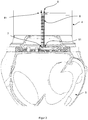
- FIG 2 shows schematically the rotor hub 5 with the rotor blade 4 connected to it.
- the device for the cable guide 6 is centered between the bracket 51 of the rotor hub 5 and the blade bottom 41 of the rotor blade 4.
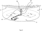
- Figure 3 shows the console 51 schematically.
- the device consists of a cable ladder 61 which is connected to the console 51 by means of fastening means 7 and to the leaf base 41 by means of fastening means 8.
- the cable ladder 61 exposes itself two parallel steel cables 62, between which rungs 63 of sheet metal or flat steel are arranged at regular intervals.
- the rungs 63 are fastened to the steel cables 62 by means of wire rope clips.
- the cables 64 are fastened to the rungs 63 in fastening holes provided for this purpose with holding means, cable ties not shown here.
- FIG 4 a section of the console 51 is shown. Furthermore, the attachment of the device according to the invention to the console 51 can be seen.
- the steel cables 62 of the cable ladder 61 are each connected to the bracket 51 by the fastening means 7.
- a fastening means 7 for fastening to the bracket 51 consists of a bolt 71 below the bracket 51, a lifting eye 72 above the bracket 51 and a spring 73 through which the bolt 71 is guided below the bracket 51.
- the stop eyelet 72 is firmly connected to the bolt 71.
- the steel cable 62 is guided through the eyelet 72 and held in the eyelet 72 by means of a thimble 65 and cable clamps.
- the fastener 7 described is very safe since the whole system cannot be torn out of the bracket 51, which is prevented by the bolt 71. It is possible that the spring 73 is only arranged on a steel cable 62, since the torsion is not so great when the rotor blade 4 is rotated by at most 90 °. However, if the distance between the leaf base 41 and the console 51 is small, for example if no extender is arranged, the fastening means 7 described can also be attached to both steel cables 62 of the cable ladder 61.
- the attachment of the cable ladder 61 to the leaf base 41 which generally consists of GRP.
- This attachment takes place via the Fastening means 8, which are firmly connected to the leaf base 41.
- sling eyelets or shackles can be firmly connected to the leaf base 41, the steel cables 62 being guided through the sling eyelets and held in the sling eyelets by means of thimbles and cable clamps.
- the above device for cable routing 6 described in detail from a rotor hub 5 into a rotor blade 4 of a wind energy installation 1 is an exemplary embodiment, it can be modified in a conventional manner to a large extent by the person skilled in the art without reducing the scope of the invention leave.
- the specific configuration of the cable conductors 61 can follow in a different form than that described here.
- the fastening means 7 and 8 can be designed in a different shape if this is necessary for reasons of space or for design reasons.
- the use of the indefinite articles "a” or "an” does not exclude that the relevant features can also be present more than once.
Landscapes
- Engineering & Computer Science (AREA)
- Life Sciences & Earth Sciences (AREA)
- Sustainable Development (AREA)
- Sustainable Energy (AREA)
- Chemical & Material Sciences (AREA)
- Combustion & Propulsion (AREA)
- Mechanical Engineering (AREA)
- General Engineering & Computer Science (AREA)
- Architecture (AREA)
- Civil Engineering (AREA)
- Structural Engineering (AREA)
- Wind Motors (AREA)
Abstract
Description
- Die vorliegende Erfindung betrifft eine Vorrichtung für eine Kabelführung von Kabeln und Leitungen zwischen einer Rotornabe und einem Rotorblatt einer Windenergieanlage. Im Folgenden wird der Begriff Kabel verwendet.
- Eine Windenergieanlage besteht üblicherweise aus einem Turm und einer um die Längsachse des Turms drehbar auf dem Turmkopf gelagerten Gondel. Die Gondel trägt den Rotor mit einer Rotornabe und mindestens einem Rotorblatt sowie einen Generator, der die von dem Rotor aus dem Wind entnommene Energie in elektrische Energie umwandelt. In Windenergieanlagen werden zum Drehen unterschiedlicher Komponenten unterschiedliche Verstelleinrichtungen eingesetzt. Beispielsweise wird ein Pitchsystem (Rotorblattverstelleinrichtung) für den Pitchwinkel (Winkeleinstellung) der Rotorblätter der Anlage benötigt. Für die Einstellung des Pitchwinkels (Blatteinstellwinkels) werden die Rotorblätter um ihre Längsachse gedreht. Das Pitchsystem ist üblicherweise Teil einer sogenannten Pitchregelung (Blatteinstellwinkelregelung).
- Das Pitchsystem ist zwischen der Rotornabe und dem Rotorblatt angeordnet. Teil des Pitchsystems ist ein Pitchlager mit einem Außenring und einem Innenring, welche drehbar zueinander gelagert sind. Die Pitchantriebe verfügen üblicherweise über einen Verstellantrieb, beispielsweise einen Elektromotor. Der Innenring ist in der Regel mit einer Verzahnung versehen, in welche das Ritzel des Verstellantriebs eingreift.
- An bzw. in dem Rotorblatt sind Sensoren, z.B. für das Detektieren von Eis am Rotorblatt, angeordnet. Auch andere elektrische Komponenten, wie eine Befeuerung am Rotorblatt oder ein Anti-Icing System benötigen eine Energieversorgung. Dazu ist eine Kabelführung von flexiblen Versorgungs- und/oder Steuerleitungen von der, in Bezug zum Rotorblatt ortsfesten Rotornabe zu dem Verbraucher am bzw. im beweglichen Rotorblatt erforderlich. Das Pitchen eines Rotorblattes erfolgt in der Regel in einem Winkelbereich von 0° bis 90°. Dabei ist für die Kabelführung die Drehbewegung des Rotorblattes ein Problem.
- Bisher wurde mit Hilfe eines Schleppkettensystems die Kabelführung von der Rotornabe ins Rotorblatt realisiert.
- Das Gebrauchsmuster
DE 202012010236 U1 offenbart beispielsweise eine Energieführungskette zur Führung von Kabeln, Schläuchen oder dergleichen zwischen einem feststehenden Versorgungsanschluss und einem beweglichen Abnehmer. Die Energieführungskette umfasst eine Vielzahl von gegeneinander schwenkbaren bzw. abwinkelbaren Gliedern, welche paarweise durch eine Gelenkverbindung miteinander verbunden sind. Längs der Energieführungskette verläuft eine Spann- bzw. Tragvorrichtung. Die Glieder sind durch Querstege miteinander verbunden. - Ähnliche Lösungen werden in den Veröffentlichungen
EP 2732519 B1 ,EP 2812599 B1 für Leitungsführungssysteme zur Aufnahme und Führung von Versorgungsleitungen zwischen zwei in einer Kreisbewegung relativ zueinander beweglichen Anschlusspunkten offenbart. -
EP 2762723 A1 beschreibt eine Kabelbündelungseinrichtung für aus der Gondel hängende im Inneren des Turms geführte Kabel, die an die Turmwandung angebunden sind. Die Kabelbündelungseinrichtung wird über mindestens zwei Spanneinrichtungen derart gehalten, dass eine Verdrehung der Kabelbündelungseinrichtung auf einen vorbestimmten Winkelbereich begrenzt ist. - In
EP 2918828 A1 wird eine Kabelträgeranordnung beschrieben, welche eine Vielzahl von Energiekabelbündeln in einem oberen Bereich eines Windkraftturms trägt. Eine Vielzahl von Kabelbündelführungen mit Durchgangsöffnungen für jeweils ein Energiekabelbündel ist in einem Abstand zueinander angeordnet. Mittels eines Versatzfixiermittels wird ein Versatzabstand zwischen aufeinanderfolgenden Kabelbündelführungen eingehalten. - Der Erfindung liegt die Aufgabe zugrunde, eine Vorrichtung bereitzustellen, die mit einfachen Mitteln eine zuverlässige und schonende Führung der Kabel von der Rotornabe in das um seine Längsachse drehbare Rotorblatt einer Windenergieanlage gestattet, wobei ein Pitchen des Rotorblattes nicht behindert und eine zuverlässige Energieversorgung der elektrischen Komponenten in bzw. am Rotorblatt gewährleistet werden soll.
- Die Lösung der Aufgabe erfolgt mit den Merkmalen der Patentansprüche.
- Die erfindungsgemäße Vorrichtung ist für eine Kabelführung von Kabeln zwischen einer Rotornabe und einem um seine Längsachse drehbaren Rotorblatt einer Windenergieanlage vorgesehen. Die Rotornabe umfasst eine Konsole und das Rotorblatt einen Blattboden. Die Vorrichtung ist dadurch gekennzeichnet, dass die Kabelführung mittig zentriert zwischen der Konsole und dem Blattboden angeordnet ist und aus einer Kabelleiter besteht.
- In einer wesentlichen Ausführung ist die Kabelleiter über Befestigungsmittel mit der Konsole elastisch verbunden und mittels Befestigungsmitteln mit dem Blattboden fest verbunden.
- Die Kabelleiter besteht aus zwei parallel verlaufenden Stahlseilen, zwischen welchen Sprossen in gleichmäßigen Abständen angeordnet sind.
- Für eine weitere wesentliche Ausführung besteht das Befestigungsmittel für eine Befestigung an der Konsole aus mehreren Teilen:
- aus einem Bolzen, welcher unterhalb der Konsole angeordnet ist,
- einer Anschlagöse, welche oberhalb der Konsole angeordnet ist, und
- einer Feder, durch welche der Bolzen unterhalb der Konsole geführt ist,
- wobei die Anschlagöse mit dem Bolzen fest verbunden ist.
- Für eine weitere wesentliche Ausführung ist die Kabelleiter an nur einem Stahlseil mit dem Befestigungsmittel elastisch verbunden oder die Kabelleiter ist an beiden Stahlseilen mit dem Befestigungsmittel elastisch verbunden.
- Für eine weitere Ausführung ist das Befestigungsmittel für eine Befestigung mit dem Blattboden fest mit diesem verbunden. Als Befestigungsmittel können hier Anschlagösen oder Schäkel zur Anwendung kommen.
- Für eine weitere Ausführung sind die Kabel mit Haltemitteln an den Sprossen in dafür vorgesehenen Befestigungslöchern fixiert. Als Haltemittel können Kabelbinder, Kabelschellen o.ä. verwendet werden.
- Der Vorteil der Erfindung liegt in darin, dass die Kabelführung einfach und kostengünstig ist. Die Vorrichtung zur Kabelführung kann überall dort angewendet werden, wo Kabel von einem drehfesten Ort in ein begrenzt rotierendes System geführt werden müssen.
- Die Erfindung wird anhand eines Ausführungsbeispiels erläutert. Hierzu zeigen
- Figur 1
- eine schematische Darstellung einer Windenergieanlage,
- Figur 2
- eine schematisch Darstellung der Rotornabe mit dem mit ihr verbundenen Rotorblatt,
- Figur 3
- eine schematische Darstellung der Konsole der Rotornabe,
- Figur 4
- einen Ausschnitt der Konsole mit einer schematischen Darstellung der Befestigung der erfindungsgemäßen Vorrichtung.
-
Figur 1 zeigt eine schematische Darstellung einer Windenergieanlage 1, welche aus einem Turm 3 und einer drehbar auf dem Turmkopf gelagerten Gondel 2 besteht. Die Gondel 2 ist mit einer Rotornabe 5 verbunden, die ihrerseits mit beispielsweise drei Rotorblättern 4 verbunden ist. Die erfindungsgemäße Vorrichtung für eine Kabelführung 6 von der Rotornabe ins Rotorblatt der Windenergieanlage 1 trägt die Signal- und Leistungskabel für die erwähnten Sensoren. Wie weiter oben auch erwähnt, stellt die Kabelführung 6 von flexiblen Versorgungs- und/oder Steuerleitungen an der Schnittstelle zwischen der Rotornabe 5 und dem Rotorblatt 4 ein Problem dar, da das Rotorblatt 4 in Bezug die ortsfeste Rotornabe 5 gedreht wird. Das Pitchen eines Rotorblattes erfolgt in der Regel in einem Winkelbereich von 0° bis 90°. Die Kabelführung 6 muss so gestaltet sein, dass die Drehbewegung des Rotorblattes 4 zu keinen Beschädigungen an den Kabeln 64 führt. -
Figur 2 zeigt schematisch die Rotornabe 5 mit dem mit ihr verbundenen Rotorblatt 4. Die Vorrichtung für die Kabelführung 6 ist mittig zentriert zwischen der Konsole 51 der Rotornabe 5 und dem Blattboden 41 des Rotorblattes 4 angeordnet.Figur 3 zeigt schematisch die Konsole 51. Die Vorrichtung besteht aus einer Kabelleiter 61, welche mittels Befestigungsmitteln 7 mit der Konsole 51 und mittels Befestigungsmitteln 8 mit dem Blattboden 41 verbunden sind. Die Kabelleiter 61 setzt sich aus zwei parallel verlaufenden Stahlseilen 62, zwischen welchen Sprossen 63 aus Blech oder Flachstahl in gleichmäßigen Abständen angeordnet sind, zusammen. Die Sprossen 63 sind mittels Drahtseilklemmen an den Stahlseilen 62 befestigt. Die Kabel 64 werden mit Haltemitteln, hier nicht weiter dargestellte Kabelbinder, an den Sprossen 63 in dafür vorgesehenen Befestigungslöchern fixiert. - In
Figur 4 ist ein Ausschnitt der Konsole 51 dargestellt. Weiterhin ist die Befestigung der erfindungsgemäßen Vorrichtung an der Konsole 51 zu sehen. Die Stahlseile 62 der Kabelleiter 61 sind jeweils durch die Befestigungsmittel 7 mit der Konsole 51 verbunden. Ein Befestigungsmittel 7 für die Befestigung an der Konsole 51 besteht aus einem Bolzen 71 unterhalb der Konsole 51, einer Anschlagöse 72 oberhalb der Konsole 51 und einer Feder 73, durch welche der Bolzen 71 unterhalb der Konsole 51 geführt wird. Die Anschlagöse 72 ist mit dem Bolzen 71 fest verbunden. Das Stahlseil 62 wird durch die Anschlagöse 72 geführt und mittels einer Kausche 65 und Kabelklemmen in der Anschlagöse 72 gehalten. Durch diese Anordnung - Stahlseil 62, Anschlagöse 72, Bolzen 71 mit Feder 73 - ist das Stahlseil 62 mittels der Feder 73 elastisch aufgehängt, wodurch sich eine gewisse Dehnung der Kabelleiter 61 einstellen kann, wenn das Rotorblatt 4 gepitcht wird und die Kabelleiter 61 einer Torsion unterliegt. Außerdem ist das beschriebene Befestigungsmittel 7 sehr sicher, da das ganze System nicht aus der Konsole 51 gerissen werden kann, was durch den Bolzen 71 verhindert wird. Es ist möglich, dass die Feder 73 lediglich an einem Stahlseil 62 angeordnet ist, da die Torsion bei einer Drehung des Rotorblattes 4 um höchstens 90° nicht so groß ist. Sollte allerdings der Abstand zwischen Blattboden 41 und Konsole 51 klein sein, beispielsweise, wenn kein Extender angeordnet ist, kann das beschriebene Befestigungsmittel 7 auch an beiden Stahlseilen 62 der Kabelleiter 61 angebracht sein. - Nicht dargestellt ist die Befestigung der Kabelleiter 61 am Blattboden 41, welcher in der Regel aus GFK besteht. Diese Befestigung erfolgt über die Befestigungsmittel 8, welche mit dem Blattboden 41 fest verbunden sind. So können beispielsweise Anschlagösen oder Schäkel mit dem Blattboden 41 fest verbunden sein, wobei die Stahlseile 62 durch die Anschlagösen geführt und mittels Kauschen und Kabelklemmen in den Anschlagösen gehalten werden.
- Da es sich bei der vorhergehenden, detailliert beschriebenen Vorrichtung für eine Kabelführung 6 von einer Rotornabe 5 in ein Rotorblatt 4 einer Windenergieanlage 1 um ein Ausführungsbeispiel handelt, kann sie in üblicher Weise vom Fachmann in einem weiten Umfang modifiziert werden, ohne den Bereich der Erfindung zu verlassen. Insbesondere kann die konkrete Ausgestaltung der Kabelleiter 61 in anderer Form als in der hier beschriebenen folgen. Ebenso können die Befestigungsmittel 7 und 8 in einer anderen Form ausgestaltet werden, wenn dies aus Platzgründen bzw. designerischen Gründen notwendig ist. Weiter schließt die Verwendung der unbestimmten Artikel "ein" bzw. "eine" nicht aus, dass die betreffenden Merkmale auch mehrfach vorhanden sein können.
-
- 1
- Windenergieanlage
- 2
- Gondel
- 3
- Turm
- 4
- Rotorblatt
41 Blattboden eines Rotorblattes 4 - 5
- Rotornabe
51 Konsole der Rotornabe 5 - 6
- Kabelführung
61 Kabelleiter
62 Stahlseile
63 Sprossen
64 Kabel
65 Kausche - 7
- Befestigungsmittel an der Konsole 51
71 Bolzen
72 Anschlagöse
73 Feder - 8
- Befestigungsmittel am Blattboden 41
Claims (9)
- Vorrichtung für eine Kabelführung (6) von Kabeln (64) zwischen einer Rotornabe (5) und einem um seine Längsachse drehbaren Rotorblatt (4) einer Windenergieanlage (1), wobei die Rotornabe (5) eine Konsole (51) und das Rotorblatt (4) einen Blattboden (41) umfassen, dadurch gekennzeichnet, dass die Kabelführung (6) mittig zentriert zwischen der Konsole (51) und dem Blattboden (41) angeordnet ist und aus einer Kabelleiter (61) besteht.
- Vorrichtung nach Anspruch 1 dadurch gekennzeichnet, dass die Kabelleiter (61) über Befestigungsmittel (7) mit der Konsole (51) elastisch verbunden ist und mittels Befestigungsmitteln (8) mit dem Blattboden (41) fest verbunden ist.
- Vorrichtung nach Anspruch 1 oder 2 dadurch gekennzeichnet, dass die Kabelleiter (61) aus zwei parallel verlaufenden Stahlseilen (62) besteht, zwischen welchen Sprossen (63) in gleichmäßigen Abständen angeordnet sind.
- Vorrichtung nach Anspruch 2 dadurch gekennzeichnet, dass das Befestigungsmittel (7) für eine Befestigung an der Konsole (51) aus einem Bolzen (71), welcher unterhalb der Konsole (51) angeordnet ist, einer Anschlagöse (72), welche oberhalb der Konsole (51) angeordnet ist, und einer Feder (73), durch welche der Bolzen (71) unterhalb der Konsole (51) geführt ist, besteht, wobei die Anschlagöse (72) mit dem Bolzen (71) fest verbunden ist.
- Vorrichtung nach einem der Ansprüche 2 bis 4 dadurch gekennzeichnet, dass die Kabelleiter (61) an nur einem Stahlseil (62) mit dem Befestigungsmittel (7) elastisch verbunden ist.
- Vorrichtung nach einem der Ansprüche 2 bis 4 dadurch gekennzeichnet, dass die Kabelleiter (61) an beiden Stahlseilen (62) mit dem Befestigungsmittel (7) elastisch verbunden ist.
- Vorrichtung nach Anspruch 2 dadurch gekennzeichnet, dass das Befestigungsmittel (8) für eine Befestigung mit dem Blattboden (41) fest mit diesem verbunden ist.
- Vorrichtung nach Anspruch 7 dadurch gekennzeichnet, dass das Befestigungsmittel (8) für eine Befestigung mit dem Blattboden (41) Anschlagösen oder Schäkel sind.
- Vorrichtung nach einem der vorhergehenden Ansprüche dadurch gekennzeichnet, dass
die Kabel (64) mit Haltemitteln an den Sprossen (63) in dafür vorgesehenen Befestigungslöchern fixiert sind.
Priority Applications (4)
| Application Number | Priority Date | Filing Date | Title |
|---|---|---|---|
| DK18192647.8T DK3620653T3 (da) | 2018-09-05 | 2018-09-05 | Anordning til en kabelføring af kabler mellem et rotornav og et rotorblad i et vindenergianlæg |
| ES18192647T ES2857907T3 (es) | 2018-09-05 | 2018-09-05 | Dispositivo para una guía de cables para cables entre buje y pala de rotor de una turbina eólica |
| EP18192647.8A EP3620653B1 (de) | 2018-09-05 | 2018-09-05 | Vorrichtung für eine kabelführung von kabeln zwischen rotornabe und einem rotorblatt einer windenergieanlage |
| US16/536,046 US11280321B2 (en) | 2018-09-05 | 2019-08-08 | Device for a cable guide of cables between a rotor hub and a rotor blade of a wind turbine |
Applications Claiming Priority (1)
| Application Number | Priority Date | Filing Date | Title |
|---|---|---|---|
| EP18192647.8A EP3620653B1 (de) | 2018-09-05 | 2018-09-05 | Vorrichtung für eine kabelführung von kabeln zwischen rotornabe und einem rotorblatt einer windenergieanlage |
Publications (2)
| Publication Number | Publication Date |
|---|---|
| EP3620653A1 true EP3620653A1 (de) | 2020-03-11 |
| EP3620653B1 EP3620653B1 (de) | 2020-12-02 |
Family
ID=63517721
Family Applications (1)
| Application Number | Title | Priority Date | Filing Date |
|---|---|---|---|
| EP18192647.8A Active EP3620653B1 (de) | 2018-09-05 | 2018-09-05 | Vorrichtung für eine kabelführung von kabeln zwischen rotornabe und einem rotorblatt einer windenergieanlage |
Country Status (4)
| Country | Link |
|---|---|
| US (1) | US11280321B2 (de) |
| EP (1) | EP3620653B1 (de) |
| DK (1) | DK3620653T3 (de) |
| ES (1) | ES2857907T3 (de) |
Citations (7)
| Publication number | Priority date | Publication date | Assignee | Title |
|---|---|---|---|---|
| DE202012010236U1 (de) | 2012-10-26 | 2012-11-23 | Igus Gmbh | Energieführungskette mit Spann- bzw. Tragvorrichtung |
| CN103670957A (zh) * | 2014-01-03 | 2014-03-26 | 国电联合动力技术有限公司 | 一种具有特殊电缆走线方式的风力发电机 |
| EP2762723A1 (de) | 2013-01-31 | 2014-08-06 | Nordex Energy GmbH | Turm für eine Windenergieanlage |
| EP2918828A1 (de) | 2014-03-11 | 2015-09-16 | Siemens Aktiengesellschaft | Kabelhalteranordnung |
| EP2812599B1 (de) | 2012-02-08 | 2016-09-07 | Tsubaki Kabelschlepp GmbH | Energieführungsvorrichtung für grosse verdrehwinkel |
| EP2732519B1 (de) | 2011-07-11 | 2018-01-10 | Igus GmbH | Leitungsführungssystem |
| US9982659B1 (en) * | 2017-02-03 | 2018-05-29 | General Electric Company | Methods for refurbishing wind turbines |
Family Cites Families (44)
| Publication number | Priority date | Publication date | Assignee | Title |
|---|---|---|---|---|
| US891660A (en) * | 1907-01-10 | 1908-06-23 | Metal Stamping Company | Provision-rack. |
| US1424115A (en) * | 1921-06-24 | 1922-07-25 | Richard D Nileon | Rope ladder construction |
| US1818602A (en) * | 1929-03-25 | 1931-08-11 | Western Electric Co | Support for strand material |
| US3137765A (en) * | 1961-09-11 | 1964-06-16 | Petersen Gerald A | Pulling sleeve for conductors and method of installing conductors |
| US3133725A (en) * | 1961-09-25 | 1964-05-19 | Petersen Gerald A | Stocking grip for conductor with eye |
| US5287947A (en) * | 1992-07-24 | 1994-02-22 | Mcswain Gregory A | Vertical support grid system |
| US6340141B1 (en) * | 1997-06-10 | 2002-01-22 | Cooper Technologies Company | Cable support systems, methods, and rack therefor |
| EP1149449A2 (de) * | 1998-12-17 | 2001-10-31 | Dan-Control Engineering A/S | Windkraftanlage mit kabelhalterung , kabelhalterung und halterungstraggestelldafür. |
| US6470645B1 (en) * | 2000-11-09 | 2002-10-29 | Beaird Industries, Inc. | Method for making and erecting a wind tower |
| CA2498870C (en) * | 2004-12-17 | 2006-01-24 | Structure D'acier Orleans Inc. | Suspended cable scaffold assembly |
| US10003179B2 (en) * | 2008-01-21 | 2018-06-19 | Southwire Company, Llc | Integrated systems facilitating wire and cable installations |
| US20090206610A1 (en) * | 2008-02-15 | 2009-08-20 | Negel Martin | Cable guard and method of installation |
| US20100006710A1 (en) * | 2008-07-08 | 2010-01-14 | General Electric Company | Cable bridge for a wind turbine tower |
| CN101737273A (zh) * | 2008-11-17 | 2010-06-16 | 维斯塔斯风力系统集团公司 | 塔架、风力发电机组以及在塔架内设置平台的方法 |
| DE102009013186B4 (de) * | 2008-12-19 | 2015-05-28 | Senvion Se | Turm einer Windenergieanlage |
| US8231347B2 (en) * | 2009-02-04 | 2012-07-31 | Frontier Wind, Llc | Mass-centralizing blade extension drive mount locations for wind turbine |
| WO2010108538A1 (en) * | 2009-03-24 | 2010-09-30 | Amsc Windtec Gmbh | Development of a new tower cabling |
| DE102009041982A1 (de) * | 2009-09-17 | 2011-04-14 | Schuler Pressen Gmbh & Co. Kg | Verfahren zur Leitungsmontage im Turm einer Windkraftanlage |
| CN102265030B (zh) * | 2010-03-15 | 2014-12-17 | 三菱重工业株式会社 | 风力发电装置及使用于该装置的电缆支承结构 |
| KR101277856B1 (ko) * | 2010-03-31 | 2013-06-27 | 미츠비시 쥬고교 가부시키가이샤 | 풍력 발전 장치 |
| ES2601779T3 (es) * | 2010-06-03 | 2017-02-16 | Ae Rotor Holding B.V. | Torre para una turbina eólica |
| DE102010027498B4 (de) * | 2010-07-16 | 2012-08-23 | Flyteg Gmbh & Co. Kg | Verfahren und Vorrichtung zum Reparieren oder Austauschen von Stromschienen an Windkraftanlagen |
| US20120080266A1 (en) * | 2010-10-01 | 2012-04-05 | Jack Brock | Mast, ladder, platform (mlp) assembly and method |
| EP2518844B1 (de) * | 2011-04-27 | 2013-11-13 | Siemens Aktiengesellschaft | Anordnung und Verfahren zur Installation von Kabeln |
| US8366396B2 (en) * | 2011-11-28 | 2013-02-05 | General Electric Company | Unit for cable management and wind turbine |
| KR102078997B1 (ko) * | 2012-10-04 | 2020-02-19 | 하이닥 악세서리즈 게엠베하 | 풍력 터빈에서 케이블을 라우팅하기 위한 장치 |
| DK201270766A (en) * | 2012-12-06 | 2014-06-06 | Envision Energy Denmark Aps | System for twisting cables in a wind turbine tower |
| DE102013011952A1 (de) * | 2013-07-18 | 2015-01-22 | Ssb Wind Systems Gmbh & Co. Kg | Rotor einer Windkraftanlage |
| DE102013214920A1 (de) * | 2013-07-30 | 2015-02-05 | Wobben Properties Gmbh | Windenergieanlage |
| WO2015091152A1 (en) * | 2013-12-19 | 2015-06-25 | Koninklijke Philips N.V. | Pivot cable solution |
| US9487960B2 (en) * | 2014-06-17 | 2016-11-08 | One Energy Enterprises Llc | Suspended deck systems, kits, and methods of installing, inspecting, and repairing a suspended deck system |
| WO2016049941A1 (en) * | 2014-10-03 | 2016-04-07 | General Electric Company | Spacer for wind turbine cables |
| ES2594452B1 (es) * | 2015-06-17 | 2017-09-28 | Gamesa Innovation & Technology, S.L. | Sistema pararrayos para palas de aerogenerador con un área efectiva de inyección en laminados de fibra de carbono y una distribución equilibrada de la intensidad y el voltaje de las corrientes de rayo entre distintos caminos conductores |
| KR20180026753A (ko) * | 2015-07-03 | 2018-03-13 | 베스타스 윈드 시스템스 에이/에스 | 풍력 설비의 케이블 인터페이스 |
| US10047725B2 (en) * | 2015-10-12 | 2018-08-14 | General Electric Company | Ladder attachment system for a wind turbine |
| DE102015014563A1 (de) * | 2015-11-11 | 2017-05-11 | Hydac International Gmbh | Führungsvorrichtung für strangförmige Bauteile, wie energie- und/oder informationsführende Kabel von Windkraftanlagen |
| US10408365B2 (en) * | 2016-04-21 | 2019-09-10 | O'Brien Holding Co., Inc. | Tubing bundle supports and support systems |
| US10344743B2 (en) * | 2016-05-13 | 2019-07-09 | Erico International Corporation | Lightning protection system and method for wind turbine blades |
| US11225947B2 (en) * | 2016-06-20 | 2022-01-18 | Vestas Wind Systems A/S | Method of securing cables to a wind turbine blade |
| CN109563806B (zh) * | 2016-06-30 | 2021-05-04 | 维斯塔斯风力系统集团公司 | 堆叠布置结构中的汇流条 |
| US20180313469A1 (en) * | 2017-04-28 | 2018-11-01 | Cable Management Solutions Inc. | Apparatus for routing cables through a cable support system |
| BE1025030B1 (nl) * | 2017-08-04 | 2018-10-03 | GeoSea N.V. | Zelfdragende steunconstructie voor windturbine-apparatuur |
| US11215164B2 (en) * | 2018-08-25 | 2022-01-04 | Samuel Messinger | Wind turbine propeller regulator to produce uninterrupted electricity and longer bearing life |
| US10975842B2 (en) * | 2018-08-25 | 2021-04-13 | Samuel Messinger | Wind turbine propeller regulator to produce uninterrupted electricity and longer bearing life |
-
2018
- 2018-09-05 EP EP18192647.8A patent/EP3620653B1/de active Active
- 2018-09-05 DK DK18192647.8T patent/DK3620653T3/da active
- 2018-09-05 ES ES18192647T patent/ES2857907T3/es active Active
-
2019
- 2019-08-08 US US16/536,046 patent/US11280321B2/en active Active
Patent Citations (7)
| Publication number | Priority date | Publication date | Assignee | Title |
|---|---|---|---|---|
| EP2732519B1 (de) | 2011-07-11 | 2018-01-10 | Igus GmbH | Leitungsführungssystem |
| EP2812599B1 (de) | 2012-02-08 | 2016-09-07 | Tsubaki Kabelschlepp GmbH | Energieführungsvorrichtung für grosse verdrehwinkel |
| DE202012010236U1 (de) | 2012-10-26 | 2012-11-23 | Igus Gmbh | Energieführungskette mit Spann- bzw. Tragvorrichtung |
| EP2762723A1 (de) | 2013-01-31 | 2014-08-06 | Nordex Energy GmbH | Turm für eine Windenergieanlage |
| CN103670957A (zh) * | 2014-01-03 | 2014-03-26 | 国电联合动力技术有限公司 | 一种具有特殊电缆走线方式的风力发电机 |
| EP2918828A1 (de) | 2014-03-11 | 2015-09-16 | Siemens Aktiengesellschaft | Kabelhalteranordnung |
| US9982659B1 (en) * | 2017-02-03 | 2018-05-29 | General Electric Company | Methods for refurbishing wind turbines |
Also Published As
| Publication number | Publication date |
|---|---|
| US11280321B2 (en) | 2022-03-22 |
| EP3620653B1 (de) | 2020-12-02 |
| DK3620653T3 (da) | 2021-03-08 |
| US20200072198A1 (en) | 2020-03-05 |
| ES2857907T3 (es) | 2021-09-29 |
Similar Documents
| Publication | Publication Date | Title |
|---|---|---|
| DE10303555B4 (de) | Verfahren zur kranlosen Montage eines Rotorblattes einer Windenergieanlage | |
| EP2163504B1 (de) | Verfahren zum Hochheben von Komponenten von Windenenergieanlagen | |
| EP2409031B1 (de) | Windenergieanlage mit verdrillbarer gondel-kabelführung | |
| EP2807107B1 (de) | Verfahren und vorrichtung zum montieren einer rotornabe einer windenergieanlage | |
| EP3710694B1 (de) | Flanschgestell und montageset zur vormontage und/oder zum transport und/oder zur montage eines turmsegments für eine windenergieanlage sowie verfahren | |
| EP3211217B1 (de) | Verfahren und vorrichtung zum montieren eines rotors einer windenergieanlage | |
| EP3011169B1 (de) | Verfahren zum montieren eines windenergieanlagen-rotorblattes sowie windenergieanlagen-rotorblatt | |
| DE102013214920A1 (de) | Windenergieanlage | |
| DE202013105758U1 (de) | Halte-, Hebe- und Sicherungsvorrichtung zur Anbringung an hohen, turmartigen Bauwerken | |
| EP2762723B1 (de) | Windenergieanlage mit Turm und Kabeln im Turm | |
| EP3514099B1 (de) | Vorrichtung zur befestigung eines kran- oder führungsseils an einem rotorblatt einer windenergieanlage | |
| DE102010060639A1 (de) | Arbeitsbühnenanlage | |
| DE102017128143B3 (de) | Wartungsplattform zur Wartung von Einbauten in einem Turm für eine Windenergieanlage und Anordnung einer Wartungsplattform | |
| DE102017006635A1 (de) | Montagehilfe und -Verfahren für die Einpassung von Bauelementen in Windkraftanlagen | |
| DE102013011952A1 (de) | Rotor einer Windkraftanlage | |
| WO2020224909A1 (de) | Kabelhalterung für ein kabel einer windenergieanlage und verfahren | |
| EP3620653B1 (de) | Vorrichtung für eine kabelführung von kabeln zwischen rotornabe und einem rotorblatt einer windenergieanlage | |
| DE102016206708A1 (de) | Windkraftanlage zur Bereitstellung elektrischer Leistung im Megawattbereich | |
| DE102006008428B4 (de) | Montage/Demontage eines Rotorblattes | |
| DE102015102461A1 (de) | Windkraftanlage mit Vorstage an den Rotorblättern | |
| DE202017106870U1 (de) | Vorrichtung zur Anordnung einer Hindernisbefeuerung für eine Windenergieanlage | |
| DE102011101443A1 (de) | Windkraftanlage mit verstellbaren Rotorblättern | |
| EP3460239B1 (de) | Kabelsattel zum stützen von kabeln in einer kabelschlaufe einer windkraftanlage | |
| DE102017002015B4 (de) | Energieerzeugungsvorrichtung | |
| EP3441610B1 (de) | Vorrichtung für eine verbindung zwischen einem maschinenhaus und einer rotornabe einer windenergieanlage und windenergieanlage |
Legal Events
| Date | Code | Title | Description |
|---|---|---|---|
| PUAI | Public reference made under article 153(3) epc to a published international application that has entered the european phase |
Free format text: ORIGINAL CODE: 0009012 |
|
| STAA | Information on the status of an ep patent application or granted ep patent |
Free format text: STATUS: REQUEST FOR EXAMINATION WAS MADE |
|
| 17P | Request for examination filed |
Effective date: 20190521 |
|
| AK | Designated contracting states |
Kind code of ref document: A1 Designated state(s): AL AT BE BG CH CY CZ DE DK EE ES FI FR GB GR HR HU IE IS IT LI LT LU LV MC MK MT NL NO PL PT RO RS SE SI SK SM TR |
|
| AX | Request for extension of the european patent |
Extension state: BA ME |
|
| GRAP | Despatch of communication of intention to grant a patent |
Free format text: ORIGINAL CODE: EPIDOSNIGR1 |
|
| STAA | Information on the status of an ep patent application or granted ep patent |
Free format text: STATUS: GRANT OF PATENT IS INTENDED |
|
| INTG | Intention to grant announced |
Effective date: 20200414 |
|
| GRAS | Grant fee paid |
Free format text: ORIGINAL CODE: EPIDOSNIGR3 |
|
| GRAA | (expected) grant |
Free format text: ORIGINAL CODE: 0009210 |
|
| STAA | Information on the status of an ep patent application or granted ep patent |
Free format text: STATUS: THE PATENT HAS BEEN GRANTED |
|
| AK | Designated contracting states |
Kind code of ref document: B1 Designated state(s): AL AT BE BG CH CY CZ DE DK EE ES FI FR GB GR HR HU IE IS IT LI LT LU LV MC MK MT NL NO PL PT RO RS SE SI SK SM TR |
|
| REG | Reference to a national code |
Ref country code: DE Ref legal event code: R081 Ref document number: 502018003167 Country of ref document: DE Owner name: NORDEX ENERGY SE & CO. KG, DE Free format text: FORMER OWNER: NORDEX ENERGY GMBH, 22419 HAMBURG, DE Ref country code: GB Ref legal event code: FG4D Free format text: NOT ENGLISH |
|
| REG | Reference to a national code |
Ref country code: AT Ref legal event code: REF Ref document number: 1341207 Country of ref document: AT Kind code of ref document: T Effective date: 20201215 Ref country code: CH Ref legal event code: EP |
|
| REG | Reference to a national code |
Ref country code: DE Ref legal event code: R096 Ref document number: 502018003167 Country of ref document: DE |
|
| REG | Reference to a national code |
Ref country code: IE Ref legal event code: FG4D Free format text: LANGUAGE OF EP DOCUMENT: GERMAN |
|
| REG | Reference to a national code |
Ref country code: DK Ref legal event code: T3 Effective date: 20210302 |
|
| PG25 | Lapsed in a contracting state [announced via postgrant information from national office to epo] |
Ref country code: NO Free format text: LAPSE BECAUSE OF FAILURE TO SUBMIT A TRANSLATION OF THE DESCRIPTION OR TO PAY THE FEE WITHIN THE PRESCRIBED TIME-LIMIT Effective date: 20210302 Ref country code: GR Free format text: LAPSE BECAUSE OF FAILURE TO SUBMIT A TRANSLATION OF THE DESCRIPTION OR TO PAY THE FEE WITHIN THE PRESCRIBED TIME-LIMIT Effective date: 20210303 Ref country code: FI Free format text: LAPSE BECAUSE OF FAILURE TO SUBMIT A TRANSLATION OF THE DESCRIPTION OR TO PAY THE FEE WITHIN THE PRESCRIBED TIME-LIMIT Effective date: 20201202 Ref country code: RS Free format text: LAPSE BECAUSE OF FAILURE TO SUBMIT A TRANSLATION OF THE DESCRIPTION OR TO PAY THE FEE WITHIN THE PRESCRIBED TIME-LIMIT Effective date: 20201202 |
|
| REG | Reference to a national code |
Ref country code: NL Ref legal event code: MP Effective date: 20201202 |
|
| PG25 | Lapsed in a contracting state [announced via postgrant information from national office to epo] |
Ref country code: BG Free format text: LAPSE BECAUSE OF FAILURE TO SUBMIT A TRANSLATION OF THE DESCRIPTION OR TO PAY THE FEE WITHIN THE PRESCRIBED TIME-LIMIT Effective date: 20210302 Ref country code: LV Free format text: LAPSE BECAUSE OF FAILURE TO SUBMIT A TRANSLATION OF THE DESCRIPTION OR TO PAY THE FEE WITHIN THE PRESCRIBED TIME-LIMIT Effective date: 20201202 Ref country code: PL Free format text: LAPSE BECAUSE OF FAILURE TO SUBMIT A TRANSLATION OF THE DESCRIPTION OR TO PAY THE FEE WITHIN THE PRESCRIBED TIME-LIMIT Effective date: 20201202 Ref country code: SE Free format text: LAPSE BECAUSE OF FAILURE TO SUBMIT A TRANSLATION OF THE DESCRIPTION OR TO PAY THE FEE WITHIN THE PRESCRIBED TIME-LIMIT Effective date: 20201202 |
|
| PG25 | Lapsed in a contracting state [announced via postgrant information from national office to epo] |
Ref country code: HR Free format text: LAPSE BECAUSE OF FAILURE TO SUBMIT A TRANSLATION OF THE DESCRIPTION OR TO PAY THE FEE WITHIN THE PRESCRIBED TIME-LIMIT Effective date: 20201202 Ref country code: NL Free format text: LAPSE BECAUSE OF FAILURE TO SUBMIT A TRANSLATION OF THE DESCRIPTION OR TO PAY THE FEE WITHIN THE PRESCRIBED TIME-LIMIT Effective date: 20201202 |
|
| REG | Reference to a national code |
Ref country code: LT Ref legal event code: MG9D |
|
| PG25 | Lapsed in a contracting state [announced via postgrant information from national office to epo] |
Ref country code: CZ Free format text: LAPSE BECAUSE OF FAILURE TO SUBMIT A TRANSLATION OF THE DESCRIPTION OR TO PAY THE FEE WITHIN THE PRESCRIBED TIME-LIMIT Effective date: 20201202 Ref country code: EE Free format text: LAPSE BECAUSE OF FAILURE TO SUBMIT A TRANSLATION OF THE DESCRIPTION OR TO PAY THE FEE WITHIN THE PRESCRIBED TIME-LIMIT Effective date: 20201202 Ref country code: SM Free format text: LAPSE BECAUSE OF FAILURE TO SUBMIT A TRANSLATION OF THE DESCRIPTION OR TO PAY THE FEE WITHIN THE PRESCRIBED TIME-LIMIT Effective date: 20201202 Ref country code: RO Free format text: LAPSE BECAUSE OF FAILURE TO SUBMIT A TRANSLATION OF THE DESCRIPTION OR TO PAY THE FEE WITHIN THE PRESCRIBED TIME-LIMIT Effective date: 20201202 Ref country code: SK Free format text: LAPSE BECAUSE OF FAILURE TO SUBMIT A TRANSLATION OF THE DESCRIPTION OR TO PAY THE FEE WITHIN THE PRESCRIBED TIME-LIMIT Effective date: 20201202 Ref country code: PT Free format text: LAPSE BECAUSE OF FAILURE TO SUBMIT A TRANSLATION OF THE DESCRIPTION OR TO PAY THE FEE WITHIN THE PRESCRIBED TIME-LIMIT Effective date: 20210405 Ref country code: LT Free format text: LAPSE BECAUSE OF FAILURE TO SUBMIT A TRANSLATION OF THE DESCRIPTION OR TO PAY THE FEE WITHIN THE PRESCRIBED TIME-LIMIT Effective date: 20201202 |
|
| REG | Reference to a national code |
Ref country code: DE Ref legal event code: R097 Ref document number: 502018003167 Country of ref document: DE |
|
| REG | Reference to a national code |
Ref country code: ES Ref legal event code: FG2A Ref document number: 2857907 Country of ref document: ES Kind code of ref document: T3 Effective date: 20210929 |
|
| PG25 | Lapsed in a contracting state [announced via postgrant information from national office to epo] |
Ref country code: IS Free format text: LAPSE BECAUSE OF FAILURE TO SUBMIT A TRANSLATION OF THE DESCRIPTION OR TO PAY THE FEE WITHIN THE PRESCRIBED TIME-LIMIT Effective date: 20210402 |
|
| PLBE | No opposition filed within time limit |
Free format text: ORIGINAL CODE: 0009261 |
|
| STAA | Information on the status of an ep patent application or granted ep patent |
Free format text: STATUS: NO OPPOSITION FILED WITHIN TIME LIMIT |
|
| PG25 | Lapsed in a contracting state [announced via postgrant information from national office to epo] |
Ref country code: IT Free format text: LAPSE BECAUSE OF FAILURE TO SUBMIT A TRANSLATION OF THE DESCRIPTION OR TO PAY THE FEE WITHIN THE PRESCRIBED TIME-LIMIT Effective date: 20201202 Ref country code: AL Free format text: LAPSE BECAUSE OF FAILURE TO SUBMIT A TRANSLATION OF THE DESCRIPTION OR TO PAY THE FEE WITHIN THE PRESCRIBED TIME-LIMIT Effective date: 20201202 |
|
| 26N | No opposition filed |
Effective date: 20210903 |
|
| PG25 | Lapsed in a contracting state [announced via postgrant information from national office to epo] |
Ref country code: SI Free format text: LAPSE BECAUSE OF FAILURE TO SUBMIT A TRANSLATION OF THE DESCRIPTION OR TO PAY THE FEE WITHIN THE PRESCRIBED TIME-LIMIT Effective date: 20201202 |
|
| REG | Reference to a national code |
Ref country code: CH Ref legal event code: PL |
|
| REG | Reference to a national code |
Ref country code: BE Ref legal event code: MM Effective date: 20210930 |
|
| PG25 | Lapsed in a contracting state [announced via postgrant information from national office to epo] |
Ref country code: IS Free format text: LAPSE BECAUSE OF FAILURE TO SUBMIT A TRANSLATION OF THE DESCRIPTION OR TO PAY THE FEE WITHIN THE PRESCRIBED TIME-LIMIT Effective date: 20210402 Ref country code: MC Free format text: LAPSE BECAUSE OF FAILURE TO SUBMIT A TRANSLATION OF THE DESCRIPTION OR TO PAY THE FEE WITHIN THE PRESCRIBED TIME-LIMIT Effective date: 20201202 |
|
| PG25 | Lapsed in a contracting state [announced via postgrant information from national office to epo] |
Ref country code: LU Free format text: LAPSE BECAUSE OF NON-PAYMENT OF DUE FEES Effective date: 20210905 Ref country code: IE Free format text: LAPSE BECAUSE OF NON-PAYMENT OF DUE FEES Effective date: 20210905 Ref country code: FR Free format text: LAPSE BECAUSE OF NON-PAYMENT OF DUE FEES Effective date: 20210930 Ref country code: BE Free format text: LAPSE BECAUSE OF NON-PAYMENT OF DUE FEES Effective date: 20210930 |
|
| PG25 | Lapsed in a contracting state [announced via postgrant information from national office to epo] |
Ref country code: LI Free format text: LAPSE BECAUSE OF NON-PAYMENT OF DUE FEES Effective date: 20210930 Ref country code: CH Free format text: LAPSE BECAUSE OF NON-PAYMENT OF DUE FEES Effective date: 20210930 |
|
| GBPC | Gb: european patent ceased through non-payment of renewal fee |
Effective date: 20220905 |
|
| PG25 | Lapsed in a contracting state [announced via postgrant information from national office to epo] |
Ref country code: CY Free format text: LAPSE BECAUSE OF FAILURE TO SUBMIT A TRANSLATION OF THE DESCRIPTION OR TO PAY THE FEE WITHIN THE PRESCRIBED TIME-LIMIT Effective date: 20201202 |
|
| PG25 | Lapsed in a contracting state [announced via postgrant information from national office to epo] |
Ref country code: HU Free format text: LAPSE BECAUSE OF FAILURE TO SUBMIT A TRANSLATION OF THE DESCRIPTION OR TO PAY THE FEE WITHIN THE PRESCRIBED TIME-LIMIT; INVALID AB INITIO Effective date: 20180905 |
|
| PG25 | Lapsed in a contracting state [announced via postgrant information from national office to epo] |
Ref country code: GB Free format text: LAPSE BECAUSE OF NON-PAYMENT OF DUE FEES Effective date: 20220905 |
|
| PG25 | Lapsed in a contracting state [announced via postgrant information from national office to epo] |
Ref country code: MK Free format text: LAPSE BECAUSE OF FAILURE TO SUBMIT A TRANSLATION OF THE DESCRIPTION OR TO PAY THE FEE WITHIN THE PRESCRIBED TIME-LIMIT Effective date: 20201202 |
|
| PG25 | Lapsed in a contracting state [announced via postgrant information from national office to epo] |
Ref country code: TR Free format text: LAPSE BECAUSE OF FAILURE TO SUBMIT A TRANSLATION OF THE DESCRIPTION OR TO PAY THE FEE WITHIN THE PRESCRIBED TIME-LIMIT Effective date: 20201202 |
|
| PG25 | Lapsed in a contracting state [announced via postgrant information from national office to epo] |
Ref country code: MT Free format text: LAPSE BECAUSE OF FAILURE TO SUBMIT A TRANSLATION OF THE DESCRIPTION OR TO PAY THE FEE WITHIN THE PRESCRIBED TIME-LIMIT Effective date: 20201202 |
|
| REG | Reference to a national code |
Ref country code: AT Ref legal event code: MM01 Ref document number: 1341207 Country of ref document: AT Kind code of ref document: T Effective date: 20230905 |
|
| PG25 | Lapsed in a contracting state [announced via postgrant information from national office to epo] |
Ref country code: AT Free format text: LAPSE BECAUSE OF NON-PAYMENT OF DUE FEES Effective date: 20230905 |
|
| PG25 | Lapsed in a contracting state [announced via postgrant information from national office to epo] |
Ref country code: AT Free format text: LAPSE BECAUSE OF NON-PAYMENT OF DUE FEES Effective date: 20230905 |
|
| PGFP | Annual fee paid to national office [announced via postgrant information from national office to epo] |
Ref country code: DE Payment date: 20250919 Year of fee payment: 8 Ref country code: DK Payment date: 20250922 Year of fee payment: 8 |
|
| PGFP | Annual fee paid to national office [announced via postgrant information from national office to epo] |
Ref country code: ES Payment date: 20251020 Year of fee payment: 8 |
|
| PGFP | Annual fee paid to national office [announced via postgrant information from national office to epo] |
Ref country code: AT Payment date: 20260410 Year of fee payment: 5 |