EP3620642B1 - Systeme und verfahren für aktuatormechanismus mit einzelfreiheitsgrad für schubumkehrer - Google Patents
Systeme und verfahren für aktuatormechanismus mit einzelfreiheitsgrad für schubumkehrer Download PDFInfo
- Publication number
- EP3620642B1 EP3620642B1 EP19195975.8A EP19195975A EP3620642B1 EP 3620642 B1 EP3620642 B1 EP 3620642B1 EP 19195975 A EP19195975 A EP 19195975A EP 3620642 B1 EP3620642 B1 EP 3620642B1
- Authority
- EP
- European Patent Office
- Prior art keywords
- carrier
- track
- reverser
- reverser door
- link
- Prior art date
- Legal status (The legal status is an assumption and is not a legal conclusion. Google has not performed a legal analysis and makes no representation as to the accuracy of the status listed.)
- Active
Links
Images


Classifications
-
- F—MECHANICAL ENGINEERING; LIGHTING; HEATING; WEAPONS; BLASTING
- F02—COMBUSTION ENGINES; HOT-GAS OR COMBUSTION-PRODUCT ENGINE PLANTS
- F02K—JET-PROPULSION PLANTS
- F02K1/00—Plants characterised by the form or arrangement of the jet pipe or nozzle; Jet pipes or nozzles peculiar thereto
- F02K1/54—Nozzles having means for reversing jet thrust
- F02K1/76—Control or regulation of thrust reversers
- F02K1/763—Control or regulation of thrust reversers with actuating systems or actuating devices; Arrangement of actuators for thrust reversers
-
- F—MECHANICAL ENGINEERING; LIGHTING; HEATING; WEAPONS; BLASTING
- F02—COMBUSTION ENGINES; HOT-GAS OR COMBUSTION-PRODUCT ENGINE PLANTS
- F02K—JET-PROPULSION PLANTS
- F02K1/00—Plants characterised by the form or arrangement of the jet pipe or nozzle; Jet pipes or nozzles peculiar thereto
- F02K1/54—Nozzles having means for reversing jet thrust
- F02K1/64—Reversing fan flow
- F02K1/70—Reversing fan flow using thrust reverser flaps or doors mounted on the fan housing
-
- F—MECHANICAL ENGINEERING; LIGHTING; HEATING; WEAPONS; BLASTING
- F05—INDEXING SCHEMES RELATING TO ENGINES OR PUMPS IN VARIOUS SUBCLASSES OF CLASSES F01-F04
- F05D—INDEXING SCHEME FOR ASPECTS RELATING TO NON-POSITIVE-DISPLACEMENT MACHINES OR ENGINES, GAS-TURBINES OR JET-PROPULSION PLANTS
- F05D2260/00—Function
- F05D2260/50—Kinematic linkage, i.e. transmission of position
-
- Y—GENERAL TAGGING OF NEW TECHNOLOGICAL DEVELOPMENTS; GENERAL TAGGING OF CROSS-SECTIONAL TECHNOLOGIES SPANNING OVER SEVERAL SECTIONS OF THE IPC; TECHNICAL SUBJECTS COVERED BY FORMER USPC CROSS-REFERENCE ART COLLECTIONS [XRACs] AND DIGESTS
- Y02—TECHNOLOGIES OR APPLICATIONS FOR MITIGATION OR ADAPTATION AGAINST CLIMATE CHANGE
- Y02T—CLIMATE CHANGE MITIGATION TECHNOLOGIES RELATED TO TRANSPORTATION
- Y02T50/00—Aeronautics or air transport
- Y02T50/60—Efficient propulsion technologies, e.g. for aircraft
Definitions
- the present disclosure relates generally to aircraft thrust reversers used with gas turbine engines and, more particularly, to pivot door thrust reversers.
- Turbofan gas turbine engines are known to include a fan section that produces a bypass airflow for providing the majority of engine propulsion and a core engine section through which a core airflow is compressed, mixed with fuel, combusted and expanded through a turbine to drive the fan section.
- a mixed flow turbofan engine the cool bypass airflow is ducted between a surrounding nacelle and an outer casing of the core engine section and mixed with a hot exhaust stream from the core engine section prior to discharge from the engine nozzle in a combined or mixed exhaust stream.
- the surrounding nacelle may include a thrust reverser capable of redirecting the mixed exhaust stream from a rearward direction to, at least partially, a forward direction thus producing a rearward thrust that may serve to decelerate forward motion of an aircraft and thereby assist braking the aircraft upon landing.
- Pivot door thrust reversers may be used with turbofan gas turbine engines for aircraft, including for corporate or business jets.
- Pre-exit pivot door thrust reversers may generally be characterized as including thrust reverser doors having trailing edges positioned forward of the exit plane of an exhaust duct, while post-exit pivot door thrust reversers may generally be characterized as including thrust reverser doors having trailing edges that form at least a portion of the exit plane of an exhaust duct.
- US7104500B1 discloses a thrust reverser of the prior art.
- an actuation arrangement for a thrust reverser is provided according to claim 1.
- the actuation arrangement further comprises a first link configured to be pivotally coupled to the carrier, wherein the carrier is configured to move the reverser door between the stowed position and the deployed position via the first link.
- the actuation arrangement further comprises a linear actuator configured to be coupled to the frame.
- the carrier is driven by the linear actuator.
- the carrier is configured to react loads that are parallel a line-of-action of the linear actuator from the first link into the linear actuator and configured to react loads that are non-parallel the line-of-action of the linear actuator from the first link into the track.
- the actuation arrangement further comprises a second link configured to be pivotally coupled to the carrier, wherein the carrier is configured to move a second reverser door between a stowed position and a deployed position via the second link.
- the first track lug comprises a rectangular geometry and the second track lug comprises a round geometry.
- the first track lug comprises a cutout configured to reduce a surface area of the first track lug in contact with the track.
- the actuation arrangement further comprises a liner disposed in the first groove, wherein the first track lug is configured to contact a wear surface of the liner.
- the method further comprises transferring a second load between the carrier and a second reverser door in response to the carrier translating along the track, and rotating the second reverser door between a stowed position and a deployed position in response to the carrier translating along the track.
- references to "a,” “an” or “the” may include one or more than one and that reference to an item in the singular may also include the item in the plural. Further, all ranges may include upper and lower values and all ranges and ratio limits disclosed herein may be combined.
- a thrust reverser includes an actuation arrangement including a carrier configured to translate along a single, fixed direction with respect to a reverser frame and at least one reverser door configured to move between a stowed position and a deployed position in response to the translation of the carrier with respect to the frame.
- the carrier may be driven along a track by a linear actuator.
- the actuation arrangement as provided herein, may react five degrees of freedom directly into the reverser frame, leaving the linear actuator to react only a single degree of freedom.
- an actuation arrangement as provided herein may provide for reduced actuator wear.
- An actuation arrangement can be tailored to accommodate any reverser door scheduling/timing desired. For example, one door can open faster than the other, or be delayed over the other, or the two doors can open simultaneously at a similar rate.
- An actuation arrangement may reduce overall weight of the thrust reverser. Packing of the actuation arrangement, as provided herein, may be simplified since the actuator is not necessarily "planar" with the pair of links.
- An actuation arrangement, as provided herein, may be used with a wide variety of door hinge line configurations.
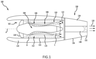
- FIG. 1 schematically illustrates a gas turbine engine 100 of a mixed flow turbofan variety.
- the gas turbine engine 100 generally includes a fan section 102 and a core engine section 104, which includes a compressor section 106, a combustor section 108 and a turbine section 110.
- the fan section 102 drives air along a bypass flow path B in a bypass duct 112 defined within a radially inner surface 115 of a nacelle 114 and an outer casing 116 of the core engine section 104, while the compressor section 106 drives air along a core flow path C of the core engine section 104 for compression and communication into the combustor section 108 and then expansion through the turbine section 110.
- the core engine section 104 may generally include a low speed spool and a high speed spool mounted for rotation about a central longitudinal axis A.
- the low speed spool generally includes an inner shaft that interconnects a fan 118 within the fan section 102, a low pressure compressor within the compressor section 106 and a low pressure turbine within the turbine section 110.
- the inner shaft may be connected to the fan 118 through a speed change mechanism or gear box to drive the fan 118 at a lower rotational speed than the rotational speed of the low speed spool.
- the high speed spool generally includes an outer shaft that interconnects a high pressure compressor within the compressor section 106 and a high pressure turbine within the turbine section 110.
- a combustor is arranged in the combustor section 108 between the high pressure compressor and the high pressure turbine.
- the air passing through the bypass flow path B mixes with the combustion gases exiting the core flow path C in a mixing section 122 positioned downstream of the core engine section 104 prior to discharge as a mixed exhaust stream 120, which provides the thrust achieved by the gas turbine engine 100.
- a thrust reverser 130 is mounted to the aft end of the gas turbine engine 100.
- the thrust reverser 130 includes a generally annular exhaust duct 132, which defines an outer boundary for discharging the mixed exhaust stream 120 when the thrust reverser 130 assumes a stowed position (also referred to as a closed position or a retracted position), as illustrated in FIG. 1 .
- the thrust reverser 130 further includes an upper reverser door 134, a lower reverser door 136 and a pair of opposing fairings 138, which may house actuator componentry and connecting members used to open and close the upper reverser door 134 and the lower reverser door 136.
- thrust reversal is affected by opening the upper reverser door 134 and the lower reverser door 136 to direct all or a portion of the mixed exhaust stream 120 in a direction having an upstream component relative to the central longitudinal axis A of the gas turbine engine 100.
- the momentum of the upstream component of the mixed exhaust stream 120 exiting the thrust reverser 130 while in an open or deployed position provides the reverse thrust used to decelerate an aircraft upon landing or during a rejected takeoff.
- the thrust reverser 200 includes an upper reverser door 202, a lower reverser door 204, and a frame 206.
- the frame 206 includes an annular structure 207 with a pair of opposing side beams 208 extending from the annular structure 207.
- the pair of opposing side beams 208 may include a port side beam 209 and a starboard side beam.
- the pair of opposing side beams 208 may provide a structural support for mounting related components and operating the thrust reverser 200 between deployed and retracted positions.
- Upper reverser door 202 is moveable relative to frame 206.
- Lower reverser door 204 is moveable relative to frame 206.
- upper reverser door 202 is rotatably coupled to frame 206 via a hinge 212 (also referred to herein as a first hinge).
- lower reverser door 204 is rotatably coupled to frame 206 via a hinge 214 (also referred to herein as a second hinge). It is contemplated herein that hinge 212 and hinge 214 may comprise two distinct hinges, or may comprise a common hinge, depending on the thrust reverser design.
- an actuation arrangement 210 (also referred to herein as a single degree of freedom actuation arrangement) is mounted to the port side beam 209.
- a fairing e.g., see fairing 138 of FIG. 1
- said fairing may be included to provide an aerodynamic surface extending between, and generally flush with upper reverser door 202 and lower reverser door 204.
- a second actuation arrangement is mounted to the starboard side beam. The second actuation arrangement may be similar to actuation arrangement 210 and the two actuation arrangements may be generally symmetric about central axis A.
- the starboard side actuation arrangement and side beam configuration may be symmetrical with the port side actuation arrangement and side beam configuration described herein.
- the starboard side may comprise a similar arrangement as the port side.
- actuation arrangement 210 may include one or more components mounted to port side beam 209. Actuation arrangement 210 is configured to facilitate rotation of the upper reverser door 202 and the lower reverser door 204 between open or deployed and closed or stowed states within the thrust reverser 200. Actuation arrangement 210 comprises a track 220 and a carrier 222 operatively coupled to the track. The carrier 222 may be configured to translate along the track 220. Carrier 222 may be moveable between a first position (see FIG. 2A ) corresponding to a closed position of the thrust reverser doors, and a second position (see FIG. 3A ) corresponding to an open position of the thrust reverser doors.
- Actuation arrangement 210 may further comprise a first link 224 and a second link 226.
- First link 224 may be pivotally coupled to carrier 222 at a first end thereof via a hinge 230 and pivotally coupled to upper reverser door 202 at a second end thereof via a hinge 216.
- Second link 226 may be pivotally coupled to carrier 222 at a first end thereof via a hinge 232 and pivotally coupled to lower reverser door 204 at a second end thereof via a hinge 218.
- a load e.g., see load 250 of FIG. 3A
- first link 224 which urges upper reverser door 202 to rotate about hinge 212 towards an open position
- second link 226 which urges lower reverser door 204 to rotate about hinge 214 towards an open position
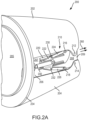
- a load (e.g., see load 250 of FIG. 3A ) is transmitted between carrier 222 and upper reverser door 202, via first link 224, which urges upper reverser door 202 to rotate about hinge 212 towards a closed position, as illustrated in FIG. 2A and FIG. 2B .
- a load (e.g., see load 252 of FIG.
- first link 224 and second link 226 may be configured to transmit tensile and compressive loads between upper reverser door 202 and carrier 222 and lower reverser door 204 and carrier 222, respectively.
- the upper reverser door 202 and the lower reverser door 204 are rotated to their closed positions ( see FIG. 2A and FIG. 2B ).
- the outer surfaces of the upper reverser door 202 and the lower reverser door 204 blend with the outer surface of the nacelle, forming a smooth aerodynamic shape of the gas turbine engine.
- a mixed gas stream 260 exits the exhaust duct 205 and is generally unaffected by the thrust reverser 200 or its componentry, as the inner surfaces of the upper reverser door 202 and the lower reverser door 204 are blended with the interior surface of the exhaust duct 205 to provide a generally smooth and annular exhaust flow path from downstream of the core engine exhaust to a downstream exit plane or aft end of the thrust reverser 200. While in the stowed position, the mixed gas stream 260 flows out the exhaust duct 205, providing forward thrust necessary to propel the aircraft.
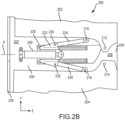
- the upper reverser door 202 and the lower reverser door 204 are rotated to their open positions ( see FIG. 3A and FIG. 3B ).
- the mixed gas stream 260 is diverted from the exit of the exhaust duct 205 to form a first stream 292, following an inner surface of the upper reverser door 202 and a second stream 294, following an inner surface of the lower reverser door 204.
- Both the first stream 292 and the second stream 294 have forward vector components of thrust, which provide the reverse thrust acting on the aircraft.
- a central axis A is illustrated extending through the thrust reverser 200.
- the central axis A may define a fore end or fore direction (negative Z-direction) of the thrust reverser 200 and an aft end or aft direction (positive Z-direction) of the thrust reverser 200.
- Various embodiments of the disclosure may be described in relation to the central axis A.
- the upper reverser door 202 may be considered positioned above the central axis A while the lower reverser door 204 may be considered positioned below the central axis A.
- the port side beam 209 may be considered positioned to the port or left side of the central axis A (looking in the fore direction (negative Z-direction)) while the starboard side beam may be considered positioned to the right or starboard side of the central axis A (looking in the fore direction).
- reference to a first reverser door may broadly refer to a reverser door positioned opposite a second reverser door with respect to the central axis A, there being no preferred up or down or side to side orientation
- reference to a first side beam may broadly refer to a side beam positioned opposite a second side beam with respect to the central axis A.
- a first component positioned opposite a second component does not imply the second component is a mirror image of the first component or the second component is positioned symmetrically opposite to the first component, though the disclosure contemplates such mirror image and symmetric configurations and positioning.
- hinge 216, hinge 218, hinge 230, and hinge 232 are floating hinges.
- the term "floating hinge” may refer to an axis of rotation of a hinge, wherein the position of the axis of rotation with respect to frame 206 varies dependent upon the position of carrier 222 with respect to track 220, and consequently the rotational position of upper reverser door 202 and/or lower reverser door 204.
- hinge 212 and hinge 214 are fixed hinges.
- fixed hinge may refer to an axis of rotation of a hinge, wherein the position of the axis of rotation is fixed with respect to frame 206 regardless of (or independent of) the position of carrier 222 with respect to track 220, and consequently the rotational position of upper reverser door 202 and/or lower reverser door 204.
- hinge 212 and hinge 214 may be floating hinges depending on the design of thrust reverser 200.
- carrier 222 is driven along track 220 via a linear actuator 240.
- linear actuator 240 is coupled to carrier 222.
- Linear actuator 240 may comprise any suitable actuator for imparting linear motion to carrier 222, including a mechanical actuator, an electromechanical actuator, a pneumatic actuator, a hydraulic actuator, among others.
- Linear actuator 240 may be mounted to frame 206.
- linear actuator 240 is coupled to frame 206.
- linear actuator 240 is coupled to bulkhead 234.
- Linear actuator 240 may comprise a moveable member 244 which may extend from an actuator housing 242 to drive, or move, carrier 222 in said first direction along track 220.
- moveable member 244 may retract or compress into actuator housing 242 to move carrier 222 in said second direction.
- linear actuator 240 may extend or retract to move carrier 222 in said first direction or said second direction along track 220 depending on the location of linear actuator 240 with respect to carrier 222.
- upper reverser door 202 and lower reverser door 204 may move between stowed and deployed positions in response to linear actuator 240 extending and/or retracting.
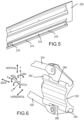
- Carrier 222 may comprise a first track lug 262 and a second track lug 264.
- Track 220 may comprise a first groove 272 and a second groove 274.
- First track lug 262 may be received by first groove 272 and second track lug 264 may be received by second groove 274.
- the carrier 222 may be retained by the track 220.
- track 220 is coupled to frame 206.
- track 220 and frame 206 are formed as a monolithic structure.
- carrier 222 interacts with the track 220 and reacts loads corresponding to five degrees of freedom (vertical, horizontal, roll, pitch, and yaw) of carrier 222 with respect to track 220, thereby transferring loads associated with these degrees of freedom from carrier 222, into track 220, and into frame 206.
- vertical may refer to movement of carrier 222 parallel the Y-axis (i.e., vertically) with respect to track 220.
- horizontal may refer to movement of carrier 222 parallel the X-axis (i.e., horizontally) with respect to track 220.
- linear actuator 240 is left to react loads between frame 206 and carrier 222 only along a single direction (single degree of freedom). Namely, linear actuator 240 transfers loads between frame 206 and carrier 222 along a line-of-action of linear actuator 240.
- linear actuator may refer to a direction, or axis, through a point at which a force is applied in the same direction as the vector of the force.
- a line-of-action of an actuator may refer to a longitudinal axis of the actuator for a single degree of freedom actuator mechanism that transfers a force along the direction of its longitudinal axis.
- said line-of-action of linear actuator 240 may be along the Z-axis illustrated in FIG. 4 . It is contemplated herein that the linear actuator 240 may further incorporate spherical type bearings at each end to accommodate manufacturing tolerances, structural deflections, etc.
- a first liner 275 is disposed between first groove 272 and first track lug 262.
- a second liner 276 is disposed between second groove 274 and second track lug 264.
- First track lug 262 may contact first liner 275.
- Second track lug 264 may contact second liner 276.
- First liner 275 and/or second liner 276 may comprise a metal material or a polymer material.
- First liner 275 and/or second liner 276 may reduce a coefficient of friction between first groove 272 and first track lug 262, and second groove 274 and second track lug 264, respectively.
- first liner 275 and/or second liner 276 may be configured as wear surfaces which may be replaced during maintenance.
- first liner 275 and/or second liner 276 may be configured as wear surfaces comprising a hardness which is greater than track 220, thereby increasing the wear life of track 220.
- Second liner 276 may conform to the geometry of second groove 274 and may extend along second groove 274 to provide a continuous surface upon which second track lug 264 may ride. Second liner 276 may be retained to track 220 via an end block 278 and/or fasteners 279.
- first track lug 262 may comprise a cutout 266 configured to reduce the surface area of first track lug 262 in contact with track 220 (see FIG. 4 ), thereby minimizing friction between carrier 222 and track 220 and furthermore reducing overall weight of carrier 222.
- second track lug 264 may comprise a cutout 268 configured to reduce the surface area of second track lug 264 in contact with track 220 (see FIG. 4 ), thereby minimizing friction between carrier 222 and track 220 and furthermore reducing overall weight of carrier 222.
- Method 700 includes translating a carrier along a track (step 710).
- Method 700 includes transferring a load between the carrier and a reverser door in response to the carrier translating along the track (step 720).
- Method 700 includes rotating the reverser door between a stowed position and a deployed position in response to the carrier translating along the track (step 730).
- step 710 may include translating carrier 222 along track 220.
- Step 710 may include translating carrier 222 aft (positive Z-direction) along track 220.
- carrier 222 is driven along track 220 via linear actuator 240.
- Step 720 may include transferring a first load, represented by arrows 250, between the carrier 222 and upper reverser door 202 in response to the carrier 222 being driven along the track 220.
- First load 250 may be transferred between carrier 222 and upper reverser door 202 via first link 224.
- Step 720 may include transferring a second load, represented by arrows 252, between the carrier 222 and lower reverser door 204 in response to the carrier 222 translating along the track 220.
- Second load 252 may be transferred between carrier 222 and upper reverser door 202 via second link 226.
- Step 730 may include rotating the upper reverser door 202 between a stowed position (see FIG. 2A ) and a deployed position (see FIG. 3A ) in response to carrier 222 translating along track 220.
- Step 730 may include rotating the lower reverser door 204 between a stowed position (see FIG. 2A ) and a deployed position (see FIG. 3A ) in response to carrier 222 translating along track 220.
- Upper reverser door 202 and lower reverser door 204 may be simultaneously rotated between the stowed position and the deployed position in response to carrier 222 translating along track 220.
- actuation arrangement 810 is illustrated mounted to frame 206.
- Actuation arrangement 810 may be similar to actuation arrangement 210, except that the first track lug 862 may be configured to react loads between carrier 222 and track 220 only along a single direction (the X-direction in FIG. 8 ) and the second track lug 864 is configured to react loads between carrier 222 and track 220 in every direction except for the forward-aft direction (the Z-direction in FIG. 8 ).
- elements with like element numbering, as depicted in FIG. 4 are intended to be the same and will not necessarily be repeated for the sake of clarity.
- Carrier 222 may comprise a first track lug 862 and a second track lug 864.
- Track 220 may comprise a first groove 872 and a second groove 874.
- First track lug 862 may be received by first groove 872 and second track lug 864 may be received by second groove 874.
- First groove 872 may be formed as a rectangular slot.
- First track lug 862 may be formed as a rectangular lug.
- first track lug 862 may be configured to carry only inboard and outboard loads (i.e., along the X-direction).
- Second groove 874 may be formed as a round slot.
- Second track lug 864 may be formed as a round, or partially round, lug. In this manner, second track lug 864 may be configured to carry inboard and outboard loads (i.e., along the X-direction) as well as tangential loads (i.e., along the Y-direction).
- references to "one embodiment”, “an embodiment”, “various embodiments”, etc. indicate that the embodiment described may include a particular feature, structure, or characteristic, but every embodiment may not necessarily include the particular feature, structure, or characteristic. Moreover, such phrases are not necessarily referring to the same embodiment. Further, when a particular feature, structure, or characteristic is described in connection with an embodiment, it is submitted that it is within the knowledge of one skilled in the art to affect such feature, structure, or characteristic in connection with other embodiments whether or not explicitly described. After reading the description, it will be apparent to one skilled in the relevant art(s) how to implement the disclosure in alternative embodiments.
Landscapes
- Engineering & Computer Science (AREA)
- Chemical & Material Sciences (AREA)
- Combustion & Propulsion (AREA)
- Mechanical Engineering (AREA)
- General Engineering & Computer Science (AREA)
- Transmission Devices (AREA)
- Sliding-Contact Bearings (AREA)
Claims (15)
- Betätigungsanordnung (210; 810) für einen Schubumkehrer (200), umfassend:eine Schiene (220), die konfiguriert ist, um an einem Rahmen (206) eines Schubumkehrers (200) angeordnet und mit diesem gekoppelt zu werden;einen Träger (222), der konfiguriert ist, um entlang der Schiene (220) verschoben zu werden; undeinen linearen Aktuator (240), der mit dem Träger (222) gekoppelt und konfiguriert ist, um mit dem Rahmen (206) gekoppelt zu werden,wobei der Träger (222) durch den linearen Aktuator (240) entlang der Schiene angetrieben wird, und der Träger (222) konfiguriert ist, um eine Umkehrerklappe (202) zwischen einer verstauten Position und einer ausgefahrenen Position zu bewegen, als Reaktion auf ein Verschieben des Trägers (222) entlang der Schiene (220),dadurch gekennzeichnet, dass:
der Träger (222) einen ersten Schienenansatz (262, 282) und einen zweiten Schienenansatz (264, 864) umfasst und die Schiene (220) eine erste Nut (272, 872), die konfiguriert ist, um den ersten Schienenansatzes (262, 862) aufzunehmen, und eine zweite Nut (274, 874), die konfiguriert ist, um den zweiten Schienenansatz (264, 864) aufzunehmen, umfasst. - Betätigungsanordnung nach Anspruch 1, ferner umfassend ein erstes Verbindungsglied (224), das konfiguriert ist, um schwenkbar mit dem Träger (222) gekoppelt zu werden, wobei der Träger (222) konfiguriert ist, um die Umkehrerklappe (202) über das erste Verbindungsglied (224) zwischen der verstauten Position und der ausgefahrenen Position zu bewegen.
- Betätigungsanordnung nach Anspruch 2, wobei der Träger (222) konfiguriert ist, um auf Lasten zu reagieren, die parallel zu einer Wirkungslinie des linearen Aktuators (240) von dem ersten Verbindungsglied (224) in den linearen Aktuator (240) verlaufen, und konfiguriert ist, um auf Lasten zu reagieren, die nicht parallel zu der Wirkungslinie des linearen Aktuators (240) von dem ersten Verbindungsglied (224) in die Schiene (220) verlaufen.
- Betätigungsanordnung nach Anspruch 2 oder 3, ferner umfassend ein zweites Verbindungsglied (226), das konfiguriert ist, um schwenkbar mit dem Träger (222) gekoppelt zu werden, wobei der Träger (222) konfiguriert ist, um eine zweite Umkehrerklappe (204) über das zweite Verbindungsglied (226) zwischen einer verstauten Position und einer ausgefahrenen Position zu bewegen.
- Betätigungsanordnung nach einem der vorhergehenden Ansprüche, wobei der erste Schienenansatz (262; 862) eine rechteckige Geometrie und der zweite Schienenansatz (264; 864) eine runde Geometrie aufweist.
- Betätigungsanordnung nach einem der vorhergehenden Ansprüche, wobei der erste Schienenansatz (262) eine Aussparung (266) aufweist, die konfiguriert ist, um eine Oberfläche des ersten Schienenansatzes (262) in Kontakt mit der Schiene (220) zu reduzieren.
- Betätigungsanordnung nach einem der vorhergehenden Ansprüche, ferner umfassend eine Auskleidung (275), die in der ersten Nut (272) angeordnet ist, wobei der erste Schienenansatz (262) konfiguriert ist, um eine Verschleißfläche der Auskleidung (275) zu kontaktieren.
- Schubumkehrer, umfassend;die Betätigungsanordnung (210; 810) nach Anspruch 1;einen Rahmen (206); undeine erste Umkehrerklappe (202), die funktionell mit dem Träger (222) gekoppelt ist;wobei die Schiene (220) an dem Rahmen angeordnet ist und die erste Umkehrerklappe (202) relativ zu dem Rahmen (206) beweglich ist, wobei die erste Umkehrerklappe (202) konfiguriert ist, um sich in eine erste Position zu bewegen, als Reaktion auf ein Bewegen des Trägers (222) in Bezug auf die Schiene (220) in eine erste Richtung, und sich in eine zweite Position zu bewegen, als Reaktion auf ein Bewegen des Trägers (222) in Bezug auf die Schiene (220) in eine zweite Richtung.
- Schubumkehrer nach Anspruch 8, wobei die erste Umkehrerklappe (202) konfiguriert ist, um sich in die erste Position zu drehen, als Reaktion auf die lineare Bewegung des Trägers (222) in Bezug auf die Schiene (220) in der ersten Richtung.
- Schubumkehrer nach Anspruch 8, ferner umfassend ein erstes Verbindungsglied (224), wobei der Träger (222) über das erste Verbindungsglied (224) mit der ersten Umkehrerklappe (202) gekoppelt ist.
- Schubumkehrer nach Anspruch 10, wobei ein erstes Ende des ersten Verbindungsglieds (224) schwenkbar mit der ersten Umkehrerklappe (202) und ein zweites Ende des ersten Verbindungsglieds (224) schwenkbar mit dem Träger (222) gekoppelt ist.
- Schubumkehrer nach Anspruch 9, ferner umfassend eine zweite Umkehrerklappe (204), die funktionell mit dem Träger (222) gekoppelt ist;wobei der Schubumkehrer optional ferner ein zweites Verbindungsglied (226) umfasst, wobei der Träger (222) über das zweite Verbindungsglied (226) mit der zweiten Umkehrerklappe (204) gekoppelt ist;wobei optional ein erstes Ende des zweiten Verbindungsglieds (226) schwenkbar mit der zweiten Umkehrerklappe (204) und ein zweites Ende des zweiten Verbindungsglieds (226) schwenkbar mit dem Träger (222) gekoppelt ist.
- Schubumkehrer nach einem der Ansprüche 9 bis 12, ferner umfassend eine Verkleidung (138), die mit dem Rahmen (206) gekoppelt und zwischen der ersten Umkehrerklappe (202) und der zweiten Umkehrerklappe (204) angeordnet ist, wobei die Verkleidung (138) vom Rahmen (206) in Bezug auf eine Mittelachse des Schubumkehrers nach außen angeordnet ist und die Verkleidung (138) mit der ersten Umkehrerklappe (202) und der zweiten Umkehrerklappe (204) bündig ist, als Reaktion auf ein Sichbefinden des Schubumkehrers in einer verstauten Position.
- Verfahren zum Ausfahren eines Schubumkehrers (200), umfassend:Verschieben eines Trägers (222) entlang einer Schiene (220), die an einem Rahmen (206) eines Schubumkehrers (200) angeordnet und mit diesem gekoppelt ist;Übertragen einer ersten Last zwischen dem Träger (222) und einer ersten Umkehrerklappe (202) als Reaktion auf das Verschieben des Trägers (222) entlang der Schiene (220), wobei der Träger (222) entlang der Schiene durch einen mit dem Rahmen (206) gekoppelten linearen Aktuator (240) angetrieben wird; undDrehen der ersten Umkehrerklappe (202) zwischen einer verstauten Position und einer ausgefahrenen Position als Reaktion auf das Verschieben des Trägers (222) entlang der Schiene (220); dadurch gekennzeichnet, dassder Träger (222) einen ersten Schienenansatz (262, 282) und einen zweiten Schienenansatz (264, 864) umfasst und die Schiene (220) eine erste Nut (272, 872), die konfiguriert ist, um den ersten Schienenansatzes (262, 862) aufzunehmen, und eine zweite Nut (274, 874), die konfiguriert ist, um den zweiten Schienenansatz (264, 864) aufzunehmen, umfasst.
- Verfahren nach Anspruch 14, wobei:Übertragen einer zweiten Last zwischen dem Träger (222) und einer zweiten Umkehrerklappe (204) als Reaktion auf das Verschieben des Trägers (222) entlang der Schiene (220); undDrehen der zweiten Umkehrerklappe (204) zwischen einer verstauten Position und einer ausgefahrenen Position als Reaktion auf das Verschieben des Trägers (222) entlang der Schiene (220).
Applications Claiming Priority (2)
| Application Number | Priority Date | Filing Date | Title |
|---|---|---|---|
| US201862728003P | 2018-09-06 | 2018-09-06 | |
| US16/560,673 US11346304B2 (en) | 2018-09-06 | 2019-09-04 | Thrust reverser single degree of freedom actuator mechanism systems and methods |
Publications (2)
| Publication Number | Publication Date |
|---|---|
| EP3620642A1 EP3620642A1 (de) | 2020-03-11 |
| EP3620642B1 true EP3620642B1 (de) | 2024-08-07 |
Family
ID=67875370
Family Applications (1)
| Application Number | Title | Priority Date | Filing Date |
|---|---|---|---|
| EP19195975.8A Active EP3620642B1 (de) | 2018-09-06 | 2019-09-06 | Systeme und verfahren für aktuatormechanismus mit einzelfreiheitsgrad für schubumkehrer |
Country Status (2)
| Country | Link |
|---|---|
| US (2) | US11346304B2 (de) |
| EP (1) | EP3620642B1 (de) |
Families Citing this family (4)
| Publication number | Priority date | Publication date | Assignee | Title |
|---|---|---|---|---|
| FR3105304B1 (fr) * | 2019-12-19 | 2021-12-10 | Safran Nacelles | Inverseur de poussée avec système d’actionnement anti-flambage |
| KR20220089223A (ko) * | 2020-12-21 | 2022-06-28 | 현대자동차주식회사 | 에어모빌리티 추진 모듈 |
| FR3129440B1 (fr) * | 2021-11-25 | 2024-07-12 | Safran Nacelles | Inverseur de poussée de nacelle d’aéronef, équipé d’un système d’actionnement à chariot |
| US11754019B2 (en) * | 2021-12-17 | 2023-09-12 | Rohr, Inc. | Articulating slider for nacelle |
Citations (1)
| Publication number | Priority date | Publication date | Assignee | Title |
|---|---|---|---|---|
| US3532275A (en) * | 1967-11-09 | 1970-10-06 | Rohr Corp | Jet reverser drive system |
Family Cites Families (23)
| Publication number | Priority date | Publication date | Assignee | Title |
|---|---|---|---|---|
| US3164956A (en) | 1963-03-14 | 1965-01-12 | Boeing Co | Two part thrust reverser |
| US3386247A (en) | 1966-09-09 | 1968-06-04 | Gen Electric | Powerplant with thrust reverser |
| US3797785A (en) * | 1972-08-31 | 1974-03-19 | Rohr Industries Inc | Thrust modulating apparatus |
| US3863867A (en) | 1973-12-26 | 1975-02-04 | Boeing Co | Thrust control apparatus for a jet propulsion engine and actuating mechanism therefor |
| FR2494775B1 (fr) | 1980-11-27 | 1985-07-05 | Astech | Dispositif pour la commande d'un inverseur de poussee pour moteur a reaction |
| FR2506843B1 (fr) | 1981-05-29 | 1987-04-24 | Hurel Dubois Avions | Dispositif d'inversion de poussee pour turboreacteur d'avion |
| US4519561A (en) | 1983-05-23 | 1985-05-28 | Rohr Industries, Inc. | Aircraft thrust reverser mechanism |
| IT1257222B (it) | 1992-06-09 | 1996-01-10 | Alenia Aeritalia & Selenia | Dispositivo inversore di spinta per motori aeronautici a getto. |
| US5730392A (en) | 1995-09-22 | 1998-03-24 | Aeronautical Concept Of Exhaust, Ltd. | Adjustable fairing for thrust reversers |
| FR2774431B1 (fr) | 1998-02-04 | 2000-03-03 | Hispano Suiza Sa | Inverseur de poussee de turboreacteur a obstacles aval |
| FR2788564B1 (fr) | 1999-01-14 | 2001-02-16 | Snecma | Tuyere d'ejection de turboreacteur a reverse integree |
| US6546716B2 (en) | 2001-04-26 | 2003-04-15 | Jean-Pierre Lair | Jet engine nozzle with variable thrust vectoring and exhaust area |
| US6487845B1 (en) | 2001-06-08 | 2002-12-03 | The Nordam Group, Inc. | Pivot fairing thrust reverser |
| US6845945B1 (en) | 2001-07-20 | 2005-01-25 | Aircraft Integration Resources, Inc. | Thrust reverser with sliding pivot joints |
| US8015797B2 (en) | 2006-09-21 | 2011-09-13 | Jean-Pierre Lair | Thrust reverser nozzle for a turbofan gas turbine engine |
| US8127546B2 (en) * | 2007-05-31 | 2012-03-06 | Solar Turbines Inc. | Turbine engine fuel injector with helmholtz resonators |
| US7735778B2 (en) | 2007-11-16 | 2010-06-15 | Pratt & Whitney Canada Corp. | Pivoting fairings for a thrust reverser |
| US8172175B2 (en) | 2007-11-16 | 2012-05-08 | The Nordam Group, Inc. | Pivoting door thrust reverser for a turbofan gas turbine engine |
| US8434715B2 (en) | 2009-07-30 | 2013-05-07 | Jean-Pierre Lair | Nested fairing thrust reverser |
| US9631578B2 (en) | 2013-02-22 | 2017-04-25 | United Technologies Corporation | Pivot thrust reverser surrounding inner surface of bypass duct |
| FR3025256B1 (fr) | 2014-08-27 | 2016-10-14 | Dassault Aviat | Dispositif deployable de plateforme et procede associe |
| US10465538B2 (en) | 2014-11-21 | 2019-11-05 | General Electric Company | Gas turbine engine with reversible fan |
| US10563615B2 (en) | 2016-05-09 | 2020-02-18 | Mra Systems, Llc | Gas turbine engine with thrust reverser assembly and method of operating |
-
2019
- 2019-09-04 US US16/560,673 patent/US11346304B2/en active Active
- 2019-09-06 EP EP19195975.8A patent/EP3620642B1/de active Active
-
2022
- 2022-05-02 US US17/734,941 patent/US11913407B2/en active Active
Patent Citations (1)
| Publication number | Priority date | Publication date | Assignee | Title |
|---|---|---|---|---|
| US3532275A (en) * | 1967-11-09 | 1970-10-06 | Rohr Corp | Jet reverser drive system |
Also Published As
| Publication number | Publication date |
|---|---|
| EP3620642A1 (de) | 2020-03-11 |
| US20200080514A1 (en) | 2020-03-12 |
| US11346304B2 (en) | 2022-05-31 |
| US20230018391A1 (en) | 2023-01-19 |
| US11913407B2 (en) | 2024-02-27 |
Similar Documents
| Publication | Publication Date | Title |
|---|---|---|
| US11913407B2 (en) | Thrust reverser single degree of freedom actuator mechanism systems and methods | |
| US12497932B2 (en) | Mixed flow exhaust thrust reverser with area control nozzle systems and methods | |
| EP3564516B1 (de) | Post-exit-schubumkehrer mit gelenkigem schwenkpunkt | |
| EP3564517B1 (de) | Hybrider artikulierender/translatorischer hinterkantenumkehrer | |
| EP3477085B1 (de) | Scharniermechanismus für drehtürschubumkehrer | |
| US11566585B2 (en) | Synchronization mechanism for pivot door thrust reversers | |
| US11873782B2 (en) | Thrust reverser actuation arrangement and deployable fairing systems and methods | |
| US12173668B2 (en) | Articulating slider for nacelle | |
| US11891966B2 (en) | Deployable fairing for door reversers systems and methods | |
| EP3620643B1 (de) | Entfaltbare verkleidung für türumkehrer, systeme und verfahren | |
| CA3015941A1 (en) | Hinge mechanism for pivot door thrust reversers |
Legal Events
| Date | Code | Title | Description |
|---|---|---|---|
| PUAI | Public reference made under article 153(3) epc to a published international application that has entered the european phase |
Free format text: ORIGINAL CODE: 0009012 |
|
| STAA | Information on the status of an ep patent application or granted ep patent |
Free format text: STATUS: THE APPLICATION HAS BEEN PUBLISHED |
|
| AK | Designated contracting states |
Kind code of ref document: A1 Designated state(s): AL AT BE BG CH CY CZ DE DK EE ES FI FR GB GR HR HU IE IS IT LI LT LU LV MC MK MT NL NO PL PT RO RS SE SI SK SM TR |
|
| AX | Request for extension of the european patent |
Extension state: BA ME |
|
| STAA | Information on the status of an ep patent application or granted ep patent |
Free format text: STATUS: REQUEST FOR EXAMINATION WAS MADE |
|
| 17P | Request for examination filed |
Effective date: 20200908 |
|
| RBV | Designated contracting states (corrected) |
Designated state(s): AL AT BE BG CH CY CZ DE DK EE ES FI FR GB GR HR HU IE IS IT LI LT LU LV MC MK MT NL NO PL PT RO RS SE SI SK SM TR |
|
| STAA | Information on the status of an ep patent application or granted ep patent |
Free format text: STATUS: EXAMINATION IS IN PROGRESS |
|
| 17Q | First examination report despatched |
Effective date: 20220408 |
|
| GRAP | Despatch of communication of intention to grant a patent |
Free format text: ORIGINAL CODE: EPIDOSNIGR1 |
|
| STAA | Information on the status of an ep patent application or granted ep patent |
Free format text: STATUS: GRANT OF PATENT IS INTENDED |
|
| RIC1 | Information provided on ipc code assigned before grant |
Ipc: F02K 1/70 20060101ALI20240209BHEP Ipc: F02K 1/76 20060101ALI20240209BHEP Ipc: F02K 1/68 20060101AFI20240209BHEP |
|
| INTG | Intention to grant announced |
Effective date: 20240228 |
|
| GRAS | Grant fee paid |
Free format text: ORIGINAL CODE: EPIDOSNIGR3 |
|
| GRAA | (expected) grant |
Free format text: ORIGINAL CODE: 0009210 |
|
| STAA | Information on the status of an ep patent application or granted ep patent |
Free format text: STATUS: THE PATENT HAS BEEN GRANTED |
|
| AK | Designated contracting states |
Kind code of ref document: B1 Designated state(s): AL AT BE BG CH CY CZ DE DK EE ES FI FR GB GR HR HU IE IS IT LI LT LU LV MC MK MT NL NO PL PT RO RS SE SI SK SM TR |
|
| REG | Reference to a national code |
Ref country code: GB Ref legal event code: FG4D |
|
| REG | Reference to a national code |
Ref country code: CH Ref legal event code: EP |
|
| REG | Reference to a national code |
Ref country code: IE Ref legal event code: FG4D |
|
| REG | Reference to a national code |
Ref country code: DE Ref legal event code: R096 Ref document number: 602019056469 Country of ref document: DE |
|
| REG | Reference to a national code |
Ref country code: LT Ref legal event code: MG9D |
|
| REG | Reference to a national code |
Ref country code: NL Ref legal event code: MP Effective date: 20240807 |
|
| PG25 | Lapsed in a contracting state [announced via postgrant information from national office to epo] |
Ref country code: NO Free format text: LAPSE BECAUSE OF FAILURE TO SUBMIT A TRANSLATION OF THE DESCRIPTION OR TO PAY THE FEE WITHIN THE PRESCRIBED TIME-LIMIT Effective date: 20241107 |
|
| REG | Reference to a national code |
Ref country code: AT Ref legal event code: MK05 Ref document number: 1711183 Country of ref document: AT Kind code of ref document: T Effective date: 20240807 |
|
| PG25 | Lapsed in a contracting state [announced via postgrant information from national office to epo] |
Ref country code: NL Free format text: LAPSE BECAUSE OF FAILURE TO SUBMIT A TRANSLATION OF THE DESCRIPTION OR TO PAY THE FEE WITHIN THE PRESCRIBED TIME-LIMIT Effective date: 20240807 Ref country code: FI Free format text: LAPSE BECAUSE OF FAILURE TO SUBMIT A TRANSLATION OF THE DESCRIPTION OR TO PAY THE FEE WITHIN THE PRESCRIBED TIME-LIMIT Effective date: 20240807 Ref country code: PL Free format text: LAPSE BECAUSE OF FAILURE TO SUBMIT A TRANSLATION OF THE DESCRIPTION OR TO PAY THE FEE WITHIN THE PRESCRIBED TIME-LIMIT Effective date: 20240807 Ref country code: GR Free format text: LAPSE BECAUSE OF FAILURE TO SUBMIT A TRANSLATION OF THE DESCRIPTION OR TO PAY THE FEE WITHIN THE PRESCRIBED TIME-LIMIT Effective date: 20241108 Ref country code: PT Free format text: LAPSE BECAUSE OF FAILURE TO SUBMIT A TRANSLATION OF THE DESCRIPTION OR TO PAY THE FEE WITHIN THE PRESCRIBED TIME-LIMIT Effective date: 20241209 |
|
| PG25 | Lapsed in a contracting state [announced via postgrant information from national office to epo] |
Ref country code: BG Free format text: LAPSE BECAUSE OF FAILURE TO SUBMIT A TRANSLATION OF THE DESCRIPTION OR TO PAY THE FEE WITHIN THE PRESCRIBED TIME-LIMIT Effective date: 20240807 |
|
| PG25 | Lapsed in a contracting state [announced via postgrant information from national office to epo] |
Ref country code: LV Free format text: LAPSE BECAUSE OF FAILURE TO SUBMIT A TRANSLATION OF THE DESCRIPTION OR TO PAY THE FEE WITHIN THE PRESCRIBED TIME-LIMIT Effective date: 20240807 |
|
| PG25 | Lapsed in a contracting state [announced via postgrant information from national office to epo] |
Ref country code: AT Free format text: LAPSE BECAUSE OF FAILURE TO SUBMIT A TRANSLATION OF THE DESCRIPTION OR TO PAY THE FEE WITHIN THE PRESCRIBED TIME-LIMIT Effective date: 20240807 Ref country code: IS Free format text: LAPSE BECAUSE OF FAILURE TO SUBMIT A TRANSLATION OF THE DESCRIPTION OR TO PAY THE FEE WITHIN THE PRESCRIBED TIME-LIMIT Effective date: 20241207 |
|
| PG25 | Lapsed in a contracting state [announced via postgrant information from national office to epo] |
Ref country code: HR Free format text: LAPSE BECAUSE OF FAILURE TO SUBMIT A TRANSLATION OF THE DESCRIPTION OR TO PAY THE FEE WITHIN THE PRESCRIBED TIME-LIMIT Effective date: 20240807 |
|
| PG25 | Lapsed in a contracting state [announced via postgrant information from national office to epo] |
Ref country code: RS Free format text: LAPSE BECAUSE OF FAILURE TO SUBMIT A TRANSLATION OF THE DESCRIPTION OR TO PAY THE FEE WITHIN THE PRESCRIBED TIME-LIMIT Effective date: 20241107 Ref country code: ES Free format text: LAPSE BECAUSE OF FAILURE TO SUBMIT A TRANSLATION OF THE DESCRIPTION OR TO PAY THE FEE WITHIN THE PRESCRIBED TIME-LIMIT Effective date: 20240807 |
|
| PG25 | Lapsed in a contracting state [announced via postgrant information from national office to epo] |
Ref country code: RS Free format text: LAPSE BECAUSE OF FAILURE TO SUBMIT A TRANSLATION OF THE DESCRIPTION OR TO PAY THE FEE WITHIN THE PRESCRIBED TIME-LIMIT Effective date: 20241107 Ref country code: PT Free format text: LAPSE BECAUSE OF FAILURE TO SUBMIT A TRANSLATION OF THE DESCRIPTION OR TO PAY THE FEE WITHIN THE PRESCRIBED TIME-LIMIT Effective date: 20241209 Ref country code: PL Free format text: LAPSE BECAUSE OF FAILURE TO SUBMIT A TRANSLATION OF THE DESCRIPTION OR TO PAY THE FEE WITHIN THE PRESCRIBED TIME-LIMIT Effective date: 20240807 Ref country code: NO Free format text: LAPSE BECAUSE OF FAILURE TO SUBMIT A TRANSLATION OF THE DESCRIPTION OR TO PAY THE FEE WITHIN THE PRESCRIBED TIME-LIMIT Effective date: 20241107 Ref country code: NL Free format text: LAPSE BECAUSE OF FAILURE TO SUBMIT A TRANSLATION OF THE DESCRIPTION OR TO PAY THE FEE WITHIN THE PRESCRIBED TIME-LIMIT Effective date: 20240807 Ref country code: LV Free format text: LAPSE BECAUSE OF FAILURE TO SUBMIT A TRANSLATION OF THE DESCRIPTION OR TO PAY THE FEE WITHIN THE PRESCRIBED TIME-LIMIT Effective date: 20240807 Ref country code: IS Free format text: LAPSE BECAUSE OF FAILURE TO SUBMIT A TRANSLATION OF THE DESCRIPTION OR TO PAY THE FEE WITHIN THE PRESCRIBED TIME-LIMIT Effective date: 20241207 Ref country code: HR Free format text: LAPSE BECAUSE OF FAILURE TO SUBMIT A TRANSLATION OF THE DESCRIPTION OR TO PAY THE FEE WITHIN THE PRESCRIBED TIME-LIMIT Effective date: 20240807 Ref country code: GR Free format text: LAPSE BECAUSE OF FAILURE TO SUBMIT A TRANSLATION OF THE DESCRIPTION OR TO PAY THE FEE WITHIN THE PRESCRIBED TIME-LIMIT Effective date: 20241108 Ref country code: FI Free format text: LAPSE BECAUSE OF FAILURE TO SUBMIT A TRANSLATION OF THE DESCRIPTION OR TO PAY THE FEE WITHIN THE PRESCRIBED TIME-LIMIT Effective date: 20240807 Ref country code: ES Free format text: LAPSE BECAUSE OF FAILURE TO SUBMIT A TRANSLATION OF THE DESCRIPTION OR TO PAY THE FEE WITHIN THE PRESCRIBED TIME-LIMIT Effective date: 20240807 Ref country code: BG Free format text: LAPSE BECAUSE OF FAILURE TO SUBMIT A TRANSLATION OF THE DESCRIPTION OR TO PAY THE FEE WITHIN THE PRESCRIBED TIME-LIMIT Effective date: 20240807 Ref country code: AT Free format text: LAPSE BECAUSE OF FAILURE TO SUBMIT A TRANSLATION OF THE DESCRIPTION OR TO PAY THE FEE WITHIN THE PRESCRIBED TIME-LIMIT Effective date: 20240807 |
|
| PG25 | Lapsed in a contracting state [announced via postgrant information from national office to epo] |
Ref country code: DK Free format text: LAPSE BECAUSE OF FAILURE TO SUBMIT A TRANSLATION OF THE DESCRIPTION OR TO PAY THE FEE WITHIN THE PRESCRIBED TIME-LIMIT Effective date: 20240807 Ref country code: SM Free format text: LAPSE BECAUSE OF FAILURE TO SUBMIT A TRANSLATION OF THE DESCRIPTION OR TO PAY THE FEE WITHIN THE PRESCRIBED TIME-LIMIT Effective date: 20240807 Ref country code: RO Free format text: LAPSE BECAUSE OF FAILURE TO SUBMIT A TRANSLATION OF THE DESCRIPTION OR TO PAY THE FEE WITHIN THE PRESCRIBED TIME-LIMIT Effective date: 20240807 |
|
| PG25 | Lapsed in a contracting state [announced via postgrant information from national office to epo] |
Ref country code: EE Free format text: LAPSE BECAUSE OF FAILURE TO SUBMIT A TRANSLATION OF THE DESCRIPTION OR TO PAY THE FEE WITHIN THE PRESCRIBED TIME-LIMIT Effective date: 20240807 |
|
| PG25 | Lapsed in a contracting state [announced via postgrant information from national office to epo] |
Ref country code: CZ Free format text: LAPSE BECAUSE OF FAILURE TO SUBMIT A TRANSLATION OF THE DESCRIPTION OR TO PAY THE FEE WITHIN THE PRESCRIBED TIME-LIMIT Effective date: 20240807 |
|
| PG25 | Lapsed in a contracting state [announced via postgrant information from national office to epo] |
Ref country code: SK Free format text: LAPSE BECAUSE OF FAILURE TO SUBMIT A TRANSLATION OF THE DESCRIPTION OR TO PAY THE FEE WITHIN THE PRESCRIBED TIME-LIMIT Effective date: 20240807 |
|
| REG | Reference to a national code |
Ref country code: CH Ref legal event code: PL |
|
| REG | Reference to a national code |
Ref country code: DE Ref legal event code: R097 Ref document number: 602019056469 Country of ref document: DE |
|
| PG25 | Lapsed in a contracting state [announced via postgrant information from national office to epo] |
Ref country code: LU Free format text: LAPSE BECAUSE OF NON-PAYMENT OF DUE FEES Effective date: 20240906 |
|
| PLBE | No opposition filed within time limit |
Free format text: ORIGINAL CODE: 0009261 |
|
| STAA | Information on the status of an ep patent application or granted ep patent |
Free format text: STATUS: NO OPPOSITION FILED WITHIN TIME LIMIT |
|
| PG25 | Lapsed in a contracting state [announced via postgrant information from national office to epo] |
Ref country code: MC Free format text: LAPSE BECAUSE OF FAILURE TO SUBMIT A TRANSLATION OF THE DESCRIPTION OR TO PAY THE FEE WITHIN THE PRESCRIBED TIME-LIMIT Effective date: 20240807 |
|
| REG | Reference to a national code |
Ref country code: BE Ref legal event code: MM Effective date: 20240930 |
|
| PG25 | Lapsed in a contracting state [announced via postgrant information from national office to epo] |
Ref country code: BE Free format text: LAPSE BECAUSE OF NON-PAYMENT OF DUE FEES Effective date: 20240930 |
|
| 26N | No opposition filed |
Effective date: 20250508 |
|
| PG25 | Lapsed in a contracting state [announced via postgrant information from national office to epo] |
Ref country code: CH Free format text: LAPSE BECAUSE OF NON-PAYMENT OF DUE FEES Effective date: 20240930 |
|
| PG25 | Lapsed in a contracting state [announced via postgrant information from national office to epo] |
Ref country code: IE Free format text: LAPSE BECAUSE OF NON-PAYMENT OF DUE FEES Effective date: 20240906 |
|
| PG25 | Lapsed in a contracting state [announced via postgrant information from national office to epo] |
Ref country code: SE Free format text: LAPSE BECAUSE OF FAILURE TO SUBMIT A TRANSLATION OF THE DESCRIPTION OR TO PAY THE FEE WITHIN THE PRESCRIBED TIME-LIMIT Effective date: 20240807 |
|
| PGFP | Annual fee paid to national office [announced via postgrant information from national office to epo] |
Ref country code: DE Payment date: 20250820 Year of fee payment: 7 |
|
| PGFP | Annual fee paid to national office [announced via postgrant information from national office to epo] |
Ref country code: GB Payment date: 20250820 Year of fee payment: 7 |
|
| PGFP | Annual fee paid to national office [announced via postgrant information from national office to epo] |
Ref country code: FR Payment date: 20250821 Year of fee payment: 7 |
|
| PG25 | Lapsed in a contracting state [announced via postgrant information from national office to epo] |
Ref country code: IT Free format text: LAPSE BECAUSE OF FAILURE TO SUBMIT A TRANSLATION OF THE DESCRIPTION OR TO PAY THE FEE WITHIN THE PRESCRIBED TIME-LIMIT Effective date: 20240807 Ref country code: CY Free format text: LAPSE BECAUSE OF FAILURE TO SUBMIT A TRANSLATION OF THE DESCRIPTION OR TO PAY THE FEE WITHIN THE PRESCRIBED TIME-LIMIT; INVALID AB INITIO Effective date: 20190906 |
|
| PG25 | Lapsed in a contracting state [announced via postgrant information from national office to epo] |
Ref country code: HU Free format text: LAPSE BECAUSE OF FAILURE TO SUBMIT A TRANSLATION OF THE DESCRIPTION OR TO PAY THE FEE WITHIN THE PRESCRIBED TIME-LIMIT; INVALID AB INITIO Effective date: 20190906 |