EP3620544A1 - Method of forming an abrasive nickel-based alloy on a turbine blade tip - Google Patents
Method of forming an abrasive nickel-based alloy on a turbine blade tip Download PDFInfo
- Publication number
- EP3620544A1 EP3620544A1 EP19185262.3A EP19185262A EP3620544A1 EP 3620544 A1 EP3620544 A1 EP 3620544A1 EP 19185262 A EP19185262 A EP 19185262A EP 3620544 A1 EP3620544 A1 EP 3620544A1
- Authority
- EP
- European Patent Office
- Prior art keywords
- metal powder
- carbon
- powder
- nickel
- turbine blade
- Prior art date
- Legal status (The legal status is an assumption and is not a legal conclusion. Google has not performed a legal analysis and makes no representation as to the accuracy of the status listed.)
- Granted
Links
Images

Classifications
-
- C—CHEMISTRY; METALLURGY
- C22—METALLURGY; FERROUS OR NON-FERROUS ALLOYS; TREATMENT OF ALLOYS OR NON-FERROUS METALS
- C22C—ALLOYS
- C22C19/00—Alloys based on nickel or cobalt
- C22C19/03—Alloys based on nickel or cobalt based on nickel
- C22C19/05—Alloys based on nickel or cobalt based on nickel with chromium
- C22C19/051—Alloys based on nickel or cobalt based on nickel with chromium and Mo or W
- C22C19/057—Alloys based on nickel or cobalt based on nickel with chromium and Mo or W with the maximum Cr content being less 10%
-
- B—PERFORMING OPERATIONS; TRANSPORTING
- B22—CASTING; POWDER METALLURGY
- B22F—WORKING METALLIC POWDER; MANUFACTURE OF ARTICLES FROM METALLIC POWDER; MAKING METALLIC POWDER; APPARATUS OR DEVICES SPECIALLY ADAPTED FOR METALLIC POWDER
- B22F5/00—Manufacture of workpieces or articles from metallic powder characterised by the special shape of the product
- B22F5/04—Manufacture of workpieces or articles from metallic powder characterised by the special shape of the product of turbine blades
-
- B—PERFORMING OPERATIONS; TRANSPORTING
- B22—CASTING; POWDER METALLURGY
- B22F—WORKING METALLIC POWDER; MANUFACTURE OF ARTICLES FROM METALLIC POWDER; MAKING METALLIC POWDER; APPARATUS OR DEVICES SPECIALLY ADAPTED FOR METALLIC POWDER
- B22F9/00—Making metallic powder or suspensions thereof
- B22F9/02—Making metallic powder or suspensions thereof using physical processes
- B22F9/06—Making metallic powder or suspensions thereof using physical processes starting from liquid material
- B22F9/08—Making metallic powder or suspensions thereof using physical processes starting from liquid material by casting, e.g. through sieves or in water, by atomising or spraying
-
- B—PERFORMING OPERATIONS; TRANSPORTING
- B23—MACHINE TOOLS; METAL-WORKING NOT OTHERWISE PROVIDED FOR
- B23K—SOLDERING OR UNSOLDERING; WELDING; CLADDING OR PLATING BY SOLDERING OR WELDING; CUTTING BY APPLYING HEAT LOCALLY, e.g. FLAME CUTTING; WORKING BY LASER BEAM
- B23K26/00—Working by laser beam, e.g. welding, cutting or boring
- B23K26/20—Bonding
- B23K26/21—Bonding by welding
-
- F—MECHANICAL ENGINEERING; LIGHTING; HEATING; WEAPONS; BLASTING
- F01—MACHINES OR ENGINES IN GENERAL; ENGINE PLANTS IN GENERAL; STEAM ENGINES
- F01D—NON-POSITIVE DISPLACEMENT MACHINES OR ENGINES, e.g. STEAM TURBINES
- F01D11/00—Preventing or minimising internal leakage of working-fluid, e.g. between stages
- F01D11/08—Preventing or minimising internal leakage of working-fluid, e.g. between stages for sealing space between rotor blade tips and stator
- F01D11/12—Preventing or minimising internal leakage of working-fluid, e.g. between stages for sealing space between rotor blade tips and stator using a rubstrip, e.g. erodible. deformable or resiliently-biased part
- F01D11/122—Preventing or minimising internal leakage of working-fluid, e.g. between stages for sealing space between rotor blade tips and stator using a rubstrip, e.g. erodible. deformable or resiliently-biased part with erodable or abradable material
-
- B—PERFORMING OPERATIONS; TRANSPORTING
- B22—CASTING; POWDER METALLURGY
- B22F—WORKING METALLIC POWDER; MANUFACTURE OF ARTICLES FROM METALLIC POWDER; MAKING METALLIC POWDER; APPARATUS OR DEVICES SPECIALLY ADAPTED FOR METALLIC POWDER
- B22F3/00—Manufacture of workpieces or articles from metallic powder characterised by the manner of compacting or sintering; Apparatus specially adapted therefor ; Presses and furnaces
- B22F3/24—After-treatment of workpieces or articles
- B22F2003/241—Chemical after-treatment on the surface
- B22F2003/242—Coating
-
- B—PERFORMING OPERATIONS; TRANSPORTING
- B22—CASTING; POWDER METALLURGY
- B22F—WORKING METALLIC POWDER; MANUFACTURE OF ARTICLES FROM METALLIC POWDER; MAKING METALLIC POWDER; APPARATUS OR DEVICES SPECIALLY ADAPTED FOR METALLIC POWDER
- B22F3/00—Manufacture of workpieces or articles from metallic powder characterised by the manner of compacting or sintering; Apparatus specially adapted therefor ; Presses and furnaces
- B22F3/24—After-treatment of workpieces or articles
- B22F2003/248—Thermal after-treatment
-
- B—PERFORMING OPERATIONS; TRANSPORTING
- B22—CASTING; POWDER METALLURGY
- B22F—WORKING METALLIC POWDER; MANUFACTURE OF ARTICLES FROM METALLIC POWDER; MAKING METALLIC POWDER; APPARATUS OR DEVICES SPECIALLY ADAPTED FOR METALLIC POWDER
- B22F2301/00—Metallic composition of the powder or its coating
- B22F2301/15—Nickel or cobalt
-
- B—PERFORMING OPERATIONS; TRANSPORTING
- B22—CASTING; POWDER METALLURGY
- B22F—WORKING METALLIC POWDER; MANUFACTURE OF ARTICLES FROM METALLIC POWDER; MAKING METALLIC POWDER; APPARATUS OR DEVICES SPECIALLY ADAPTED FOR METALLIC POWDER
- B22F2302/00—Metal Compound, non-Metallic compound or non-metal composition of the powder or its coating
- B22F2302/40—Carbon, graphite
-
- B—PERFORMING OPERATIONS; TRANSPORTING
- B22—CASTING; POWDER METALLURGY
- B22F—WORKING METALLIC POWDER; MANUFACTURE OF ARTICLES FROM METALLIC POWDER; MAKING METALLIC POWDER; APPARATUS OR DEVICES SPECIALLY ADAPTED FOR METALLIC POWDER
- B22F2303/00—Functional details of metal or compound in the powder or product
- B22F2303/20—Coating by means of particles
-
- F—MECHANICAL ENGINEERING; LIGHTING; HEATING; WEAPONS; BLASTING
- F05—INDEXING SCHEMES RELATING TO ENGINES OR PUMPS IN VARIOUS SUBCLASSES OF CLASSES F01-F04
- F05D—INDEXING SCHEME FOR ASPECTS RELATING TO NON-POSITIVE-DISPLACEMENT MACHINES OR ENGINES, GAS-TURBINES OR JET-PROPULSION PLANTS
- F05D2230/00—Manufacture
- F05D2230/20—Manufacture essentially without removing material
- F05D2230/22—Manufacture essentially without removing material by sintering
-
- F—MECHANICAL ENGINEERING; LIGHTING; HEATING; WEAPONS; BLASTING
- F05—INDEXING SCHEMES RELATING TO ENGINES OR PUMPS IN VARIOUS SUBCLASSES OF CLASSES F01-F04
- F05D—INDEXING SCHEME FOR ASPECTS RELATING TO NON-POSITIVE-DISPLACEMENT MACHINES OR ENGINES, GAS-TURBINES OR JET-PROPULSION PLANTS
- F05D2300/00—Materials; Properties thereof
- F05D2300/10—Metals, alloys or intermetallic compounds
- F05D2300/17—Alloys
- F05D2300/175—Superalloys
Definitions
- the present disclosure generally relates to turbine engine technologies. More particularly, the present disclosure relates to a method of forming an abrasive nickel-based alloy on a turbine blade tip.
- Turbine engines are used as the primary power source for various kinds of vehicles, such as aircraft. Turbine engines are also used as auxiliary power sources that drive air compressors, hydraulic pumps, and industrial gas turbine (IGT) power generation. Furthermore, the power from turbine engines may be used for stationary power supplies such as backup electrical generators and the like.
- IGT industrial gas turbine
- Turbine engines generally follow the same basic power generation procedure. Compressed air is mixed with fuel and burned, and the expanding hot combustion gases are directed against stationary turbine vanes in the engine. The vanes turn the high velocity gas flow partially sideways to impinge on the turbine blades mounted on a rotatable turbine disk. The force of the impinging gas causes the turbine disk to spin at high speed. Turbine engines use the power created by the rotating turbine disk to power a bladed compressor that draws more air into the engine and to energize fan blades, propellers, electrical generators, or other devices, depending on the type of turbine engine.
- compressors and turbines Because turbine engines provide power for many primary and secondary functions, it is important to optimize the operating efficiency of compressors and turbines.
- One way to maximize compressor and turbine efficiency is to minimize high-pressure air leakage between the tips of the blades and the adjacent shroud.
- compressor or turbine blade dimensions are tightly controlled and blade tips can be machined so the installed blades span a diameter that is just slightly smaller than the shroud inner diameter. Improvements in compressor or turbine performance are possible when compressor or turbine blade tips can tolerate interference rubs with the adjacent shroud without experiencing significant blade tip wear. That is, wear of blade tips during a rub is undesirable because clearances increase, producing an associated reduction in compressor or turbine performance.
- U.S. Patent No. 5,704,759 discloses a turbine blade body having a tip portion that is coated with an abrasive material.
- the abrasive material includes a dispersion of discrete particles of cubic boron nitride (CBN) that are formed on the blade tip by an entrapment plating method wherein the CBN particles are entrapped in electroplated nickel with their tips (cutting edges) exposed.
- CBN cubic boron nitride
- a method of forming an abrasive nickel-based alloy on a turbine blade tip includes producing or obtaining a metal powder that is mixed with a carbon powder to form a carbon-enriched metal powder.
- the metal powder includes a refractory element.
- the method further includes bonding the carbon-enriched metal powder to the turbine blade tip.
- the step of bonding includes raising the temperature of the carbon-enriched metal powder past its melting point, thereby causing the carbon to combine with the refractory elements to form abrasive carbide particles.
- a method of forming an abrasive nickel-based alloy on a turbine blade tip includes producing or obtaining a turbine blade including the turbine blade tip.
- the turbine blade includes a nickel-based superalloy.
- the method further includes producing or obtaining a metal powder that is mixed with a carbon powder to form a carbon-enriched metal powder.
- the metal powder includes a nickel-based superalloy and further includes a refractory element selected from the group consisting of tungsten, tantalum, titanium, and a mixture of two or more thereof.
- the metal and ceramic powder mixture has a weight ratio of metal powder to carbon powder of from about 100:1 to about 20:1.
- the method further includes bonding the carbon-enriched metal powder to the turbine blade tip.
- the step of bonding includes raising the temperature of the carbon-enriched metal powder past its melting point, thereby causing the carbon to combine with the refractory elements to form abrasive carbide particles. Bonding the carbon-enriched metal powder is performed using a laser deposition process or an electron-beam welding process.
- a method of forming an abrasive nickel-based alloy on a turbine blade tip includes producing or obtaining a turbine blade including the turbine blade tip.
- the turbine blade includes a nickel-based superalloy.
- the method further includes producing or obtaining a metal powder that is mixed with a carbon powder to form a carbon-enriched metal powder.
- the metal powder includes a nickel-based superalloy and further includes a refractory element selected from the group consisting of tungsten, tantalum, titanium, and a mixture of two or more thereof.
- the metal and ceramic powder mixture has a weight ratio of metal powder to carbon powder of from about 50:1 to about 25:1.
- a variance between the mean particle size (d50) of the metal powder as compared with the mean particle size (d50) of the carbon powder is +/- 25%.
- the method further includes bonding the carbon-enriched metal powder to the turbine blade tip.
- the step of bonding includes raising the temperature of the carbon-enriched metal powder past its melting point, thereby causing the carbon to combine with the refractory elements to form abrasive carbide particles. Bonding the carbon-enriched metal powder is performed using a laser deposition process or an electron-beam welding process.
- the method includes performing a finishing process on the turbine blade after the step of bonding. The finishing process is selected from the group consisting of: heat treating, machining, surface finishing, polishing, and coating.
- the word “exemplary” means “serving as an example, instance, or illustration.” Thus, any alloy embodiment described herein as “exemplary” is not necessarily to be construed as preferred or advantageous over other embodiments. All of the embodiments described herein are exemplary embodiments provided to enable persons skilled in the art to make or use the invention and not to limit the scope of the invention which is defined by the claims. As further used herein, the word “about” means a possible variance (+/-) of the stated value of up to 10%, or alternatively up to 5%, or no variance at all. Furthermore, there is no intention to be bound by any expressed or implied theory presented in the preceding technical field, background, brief summary, or the following detailed description.
- the present disclosure generally provides embodiments of a method of forming an abrasive nickel-based alloy on a turbine blade tip.
- a metal powder is prepared using an atomization process.
- the metal powder is an alloy that is suitable for use in a turbine blade, such as (but not limited to) a nickel-based superalloy.
- the metal powder includes refractory elements, such as tungsten, titanium, and/or tantalum.
- An amount of carbon in then mixed into the metal powder.
- the carbon-enriched metal powder is then bonded to the turbine blade tip using laser deposition, electron-beam welding, or any other technique that causes the carbon-enriched metal powder to melt on the turbine blade tip.
- carbide particles are very hard, and they can serve as abrasives to aid the blade tip when rubbing against the shroud.
- the turbine blade 150 is exemplary of the type of turbine blades that are used in the turbine engines.
- Turbine blades commonly have a different shape, dimension, and size depending on gas turbine engine models and applications.
- multiple turbine blades 150 are positioned in adjacent circumferential position along a hub or rotor disk.
- the turbine blades are typically made from advanced superalloys such as IN713, IN738, IN792, MarM247, GTD111, Rene142, Rene N5, SC180, and CMSX4 to name several non-exclusive examples.
- the turbine blade 150 includes an airfoil 152.
- the airfoil 152 includes a concave curvature face and a convex face. In operation, hot gases impinge on the airfoil 152 concave face and thereby provide the driving force for the turbine engine.
- the airfoil 152 includes a leading edge 162 and a trailing edge 164 that firstly and lastly encounter an air stream passing around airfoil 152.
- the blade 150 also includes a tip 160. In some applications the tip may include raised features commonly known as squealers.
- the turbine blade 150 may be mounted on a turbine disk that is part of a non-illustrated wheel.
- the blade 150 is attached to the disk by a fir tree or dovetail attachment 154 that extends downwardly from the airfoil 152 and engages a non-illustrated slot on the turbine wheel.
- a platform 156 extends longitudinally outwardly from the area where the airfoil 152 is joined to the attachment 154.
- a number of cooling channels desirably extend through the interior of the airfoil 152, ending in openings 158 in the airfoil surface.
- a metal powder is prepared using an atomization process.
- the metal powder is an alloy that is suitable for use in a turbine blade, such as (but not limited to) a nickel-based superalloy.
- nickel-based superalloys within the scope of nickel-based superalloys, some compositions have proven particularly effective for turbine blade tips. For example, U.S.
- Patent Application Publication 2014/0134353 discloses a nickel-based superalloy that includes, by weight, about 1.5% to about 5.5% chromium, about 8% to about 12% aluminum, about 4% to about 8% tantalum, about 1.5% to about 5.5% tungsten, less than about 1% of one or more of elements selected from a group consisting of boron, zirconium, yttrium, hafnium, and silicon, and a balance of nickel.
- This alloy may be laser-welded onto the tip region of a turbine blade.
- U.S. Patent Application Publication 2011/0135489 discloses a nickel-based superalloy that includes, by weight, about 5% to about 12% cobalt, about 3% to about 10% chromium, about 5.5% to about 6.3% aluminum, about 5% to about 10% tantalum, about 3% to about 10% rhenium, about 2% to about 5% of one or more of elements selected from a group consisting of platinum, ruthenium, palladium, and iridium, about 0.1% to about 1.0% hafnium, about 0.01% to about 0.4% yttrium, about 0.01% to about 0.15% silicon, and a balance of nickel.
- This alloy may be cast into the shape of a blade tip, and then diffusion bonded onto a turbine blade.
- nickel-based superalloys may be suitable for use as a turbine blade tip material of the present disclosure; the foregoing examples are intended to provide but a sampling of the possible alloy compositions.
- a metal alloy as described above is prepared in the form of a powder using an atomization process.
- the metal powder includes refractory elements, such as tungsten, titanium, and/or tantalum.
- the metal powder is mixed with an amount of carbon.
- the carbon may be provided in powdered form, having a similar particle size mean diameter (d50) to the particles of the metal powder (e.g., a variance of +/-25%, or +/- 10%).
- the carbon powder may be mixed with the metal powder at a suitable weight ratio such that, upon melting, there is a thermodynamic tendency in the melted, carbon-enriched alloy to form hard carbides with the refractory elements. This may be a weight ratio of the metal powder to the carbon powder of about 100:1 to about 20:1, such as about 50:1 to about 25:1.
- the carbon-enriched metal powder is bonded to the turbine blade tip using laser deposition, electron-beam welding, or any other technique that causes the carbon-enriched metal powder to melt on the turbine blade tip.
- the carbon-enriched metal powder there is a thermodynamic tendency of the carbon to combine with the refractory elements to form carbide particles. These carbide particles are very hard, and they can serve as abrasives to aid the blade tip when rubbing against the shroud.
- Laser deposition (welding) will be described herein as a suitable melting process; however, this description should not be considered limited or exclusive of other possible processes.
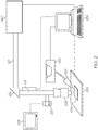
- FIG. 2 there is shown a schematic diagram of a general apparatus for laser generation and control that may be used for laser welding according to an embodiment of this disclosure.
- Laser generating means 220 generates a laser used in the welding system.
- a laser is directed through typical laser powder fusion welding equipment which may include beam guide 221, mirror 222, and focus lens 223.
- the laser then impinges on a surface of the workpiece 224 (i.e., a turbine blade).
- Components such as beam guide 221, mirror 222, and focus lens 223 are items known in the art of laser welding.
- Beam guide 221 may include fiber optic materials such as optic fiber laser transmission lines.
- a laser may be directed onto workpiece 224 through an optic fiber line.
- the carbon-enriched metal powder may be provided in powder feeder 225.
- the powder is fed onto the workpiece through powder feed nozzle 226.
- a coaxial or off-axis arrangement may be used with powder feed nozzle 226 with respect to the main laser.
- Other components of the system include vision camera 227 and video monitor 228.
- the image taken by the camera can also be fed-back to the controller screen for positioning and welding programming.
- the workpiece 224 is held on a work table 229.
- An inert gas shield (not shown) is fed through guides (not shown) onto the workpiece 224.
- the inert gas shield is directed onto a portion of the surface of the workpiece 224 during laser welding.
- Controller 230 may be a computer numerically controlled (CNC) positioning system.
- CNC controller 230 coordinates components of the system.
- the controller may also include a digital imaging system.
- the controller guides movement of the laser and powder feed across the face of the workpiece 224.
- movement of the workpiece in the XY plane is achieved through movement of the worktable 229. Movement in the up and down, or Z-direction is achieved by control of the laser arm; i.e., pulling it up or lowering it.
- the power of the laser is between about 50 to about 2500 watts and more preferably between about 50 to about 1500 watts.
- the powder feed rate of powder filler material is between about 1.5 to about 20 grams per minute and more preferably about 1.5 to about 10 grams per minute.
- Traveling speed for relative motion of the substrate positioning table 229 relative to the laser beam is about 5 to about 22 inches per minute and more preferably about 5 to about 14 inches per minute.
- the size of the main spot cast by the laser onto the work surface is about 0.02 to about 0.1 inches in diameter and more preferably about 0.04 to about 0.06 inches.
- the laser-welded bead width that results through the laser is thus about 0.02 to about 0.100 inches and more preferably about 0.04 to about 0.06 inches in width.
- the blade tip can be provided with the abrasive alloy of the present disclosure within virtually unlimited design constraints. Namely, because it is the melting of the carbon-enriched metal powder (and subsequent solidification) that causes the hard carbides to form, the act of laser welding itself creates the carbide particles. Thus, any design shape that can be produced by the laser can also include the hard carbide particles.
- the blade tip design may thus be optimized for any turbine engine configuration.
- the turbine blade may be finished using convention processes. These processes may include, but are not limited to, further heat treatments, machining, and surface finishing treatments such as polishing and coatings.
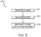
- a method 300 of forming an abrasive nickel-based alloy on a turbine blade tip. is illustrated in FIG. 3 .
- a metal powder is prepared using an atomization process.
- the metal powder is an alloy that is suitable for use in a turbine blade, such as (but not limited to) a nickel-based superalloy.
- the metal powder includes refractory elements, such as tungsten, titanium, and/or tantalum.
- an amount of carbon in mixed into the metal powder is bonded to the turbine blade tip using laser deposition, electron-beam welding, or any other technique that causes the carbon-enriched metal powder to melt on the turbine blade tip.
- the method 300 may contain additional steps not recited herein.
- the method 300 may have the method steps performed in an alternative order than as described.
- the present disclosure has provided embodiments of an improved method of forming an abrasive nickel-based alloy on a turbine blade tip.
- the method desirably avoids fabrication methods that limit the design of the blade tip by bonding the abrasive alloy to the tip using a melting technique (such as laser welding) that can accommodate virtually any design, where it is the step of melt itself (and subsequent re-solidification) of the alloy that causes the abrasive particles to be formed there-within and distributed throughout.
- a melting technique such as laser welding
Landscapes
- Engineering & Computer Science (AREA)
- Mechanical Engineering (AREA)
- Physics & Mathematics (AREA)
- Optics & Photonics (AREA)
- Chemical & Material Sciences (AREA)
- Manufacturing & Machinery (AREA)
- Plasma & Fusion (AREA)
- General Engineering & Computer Science (AREA)
- Materials Engineering (AREA)
- Metallurgy (AREA)
- Organic Chemistry (AREA)
- Powder Metallurgy (AREA)
- Laser Beam Processing (AREA)
Abstract
Description
- The present disclosure generally relates to turbine engine technologies. More particularly, the present disclosure relates to a method of forming an abrasive nickel-based alloy on a turbine blade tip.
- Turbine engines are used as the primary power source for various kinds of vehicles, such as aircraft. Turbine engines are also used as auxiliary power sources that drive air compressors, hydraulic pumps, and industrial gas turbine (IGT) power generation. Furthermore, the power from turbine engines may be used for stationary power supplies such as backup electrical generators and the like.
- Most turbine engines generally follow the same basic power generation procedure. Compressed air is mixed with fuel and burned, and the expanding hot combustion gases are directed against stationary turbine vanes in the engine. The vanes turn the high velocity gas flow partially sideways to impinge on the turbine blades mounted on a rotatable turbine disk. The force of the impinging gas causes the turbine disk to spin at high speed. Turbine engines use the power created by the rotating turbine disk to power a bladed compressor that draws more air into the engine and to energize fan blades, propellers, electrical generators, or other devices, depending on the type of turbine engine.
- Because turbine engines provide power for many primary and secondary functions, it is important to optimize the operating efficiency of compressors and turbines. One way to maximize compressor and turbine efficiency is to minimize high-pressure air leakage between the tips of the blades and the adjacent shroud. In order to accomplish this objective, compressor or turbine blade dimensions are tightly controlled and blade tips can be machined so the installed blades span a diameter that is just slightly smaller than the shroud inner diameter. Improvements in compressor or turbine performance are possible when compressor or turbine blade tips can tolerate interference rubs with the adjacent shroud without experiencing significant blade tip wear. That is, wear of blade tips during a rub is undesirable because clearances increase, producing an associated reduction in compressor or turbine performance.
- The prior art contains examples of attempted solutions to this rubbing problem by using abrasive particles embedded in the blade tip. For example,
U.S. Patent No. 5,704,759 discloses a turbine blade body having a tip portion that is coated with an abrasive material. The abrasive material includes a dispersion of discrete particles of cubic boron nitride (CBN) that are formed on the blade tip by an entrapment plating method wherein the CBN particles are entrapped in electroplated nickel with their tips (cutting edges) exposed. However, experience has shown that these abrasive tips are not durable for long-term engine use, at least in part due to limitations in the blade tip design as a result of the fabrication techniques employed. - Accordingly, it would be desirable to provide an improved method of forming an abrasive nickel-based alloy on a turbine blade tip. The method would desirably avoid fabrication methods that limit the design of the blade tip. Furthermore, other desirable features and characteristics of the disclosure will become apparent from the subsequent detailed description and the appended claims, taken in conjunction with the accompanying drawings and this background of the disclosure.
- The present disclosure relates to a method of forming an abrasive nickel-based alloy on a turbine blade tip. As such, in one exemplary embodiment, a method of forming an abrasive nickel-based alloy on a turbine blade tip includes producing or obtaining a metal powder that is mixed with a carbon powder to form a carbon-enriched metal powder. The metal powder includes a refractory element. The method further includes bonding the carbon-enriched metal powder to the turbine blade tip. The step of bonding includes raising the temperature of the carbon-enriched metal powder past its melting point, thereby causing the carbon to combine with the refractory elements to form abrasive carbide particles.
- In another exemplary embodiment, a method of forming an abrasive nickel-based alloy on a turbine blade tip includes producing or obtaining a turbine blade including the turbine blade tip. The turbine blade includes a nickel-based superalloy. The method further includes producing or obtaining a metal powder that is mixed with a carbon powder to form a carbon-enriched metal powder. The metal powder includes a nickel-based superalloy and further includes a refractory element selected from the group consisting of tungsten, tantalum, titanium, and a mixture of two or more thereof. The metal and ceramic powder mixture has a weight ratio of metal powder to carbon powder of from about 100:1 to about 20:1. The method further includes bonding the carbon-enriched metal powder to the turbine blade tip. The step of bonding includes raising the temperature of the carbon-enriched metal powder past its melting point, thereby causing the carbon to combine with the refractory elements to form abrasive carbide particles. Bonding the carbon-enriched metal powder is performed using a laser deposition process or an electron-beam welding process.
- In yet another exemplary embodiment, a method of forming an abrasive nickel-based alloy on a turbine blade tip includes producing or obtaining a turbine blade including the turbine blade tip. The turbine blade includes a nickel-based superalloy. The method further includes producing or obtaining a metal powder that is mixed with a carbon powder to form a carbon-enriched metal powder. The metal powder includes a nickel-based superalloy and further includes a refractory element selected from the group consisting of tungsten, tantalum, titanium, and a mixture of two or more thereof. The metal and ceramic powder mixture has a weight ratio of metal powder to carbon powder of from about 50:1 to about 25:1. A variance between the mean particle size (d50) of the metal powder as compared with the mean particle size (d50) of the carbon powder is +/- 25%. The method further includes bonding the carbon-enriched metal powder to the turbine blade tip. The step of bonding includes raising the temperature of the carbon-enriched metal powder past its melting point, thereby causing the carbon to combine with the refractory elements to form abrasive carbide particles. Bonding the carbon-enriched metal powder is performed using a laser deposition process or an electron-beam welding process. Still further, the method includes performing a finishing process on the turbine blade after the step of bonding. The finishing process is selected from the group consisting of: heat treating, machining, surface finishing, polishing, and coating.
- This Brief Summary is provided to describe select concepts in a simplified form that are further described in the Detailed Description. This Brief Summary is not intended to identify key or essential features of the claimed subject matter, nor is it intended to be used as an aid in determining the scope of the claimed subject matter.
- The present disclosure will hereinafter be described in conjunction with the following drawing figures, wherein like numerals denote like elements, and wherein:
-
FIG. 1 is a perspective view of a blade for a turbine according to an embodiment of the present disclosure; -
FIG. 2 is a schematic representation of the equipment and apparatus that may be used to perform laser deposition welding in accordance with an embodiment of the present disclosure; and -
FIG. 3 is a flowchart illustrating a method of forming an abrasive nickel-based alloy on a turbine blade tip in accordance with an embodiment of the present disclosure. - The following detailed description is merely exemplary in nature and is not intended to limit the invention or the application and uses of the invention. As used herein, the word "exemplary" means "serving as an example, instance, or illustration." Thus, any alloy embodiment described herein as "exemplary" is not necessarily to be construed as preferred or advantageous over other embodiments. All of the embodiments described herein are exemplary embodiments provided to enable persons skilled in the art to make or use the invention and not to limit the scope of the invention which is defined by the claims. As further used herein, the word "about" means a possible variance (+/-) of the stated value of up to 10%, or alternatively up to 5%, or no variance at all. Furthermore, there is no intention to be bound by any expressed or implied theory presented in the preceding technical field, background, brief summary, or the following detailed description.
- The present disclosure generally provides embodiments of a method of forming an abrasive nickel-based alloy on a turbine blade tip. In accordance with these embodiments, a metal powder is prepared using an atomization process. The metal powder is an alloy that is suitable for use in a turbine blade, such as (but not limited to) a nickel-based superalloy. The metal powder includes refractory elements, such as tungsten, titanium, and/or tantalum. An amount of carbon in then mixed into the metal powder. The carbon-enriched metal powder is then bonded to the turbine blade tip using laser deposition, electron-beam welding, or any other technique that causes the carbon-enriched metal powder to melt on the turbine blade tip. During the melting of the carbon-enriched metal powder, there is a thermodynamic tendency of the carbon to combine with the refractory elements to form carbide particles. These carbide particles are very hard, and they can serve as abrasives to aid the blade tip when rubbing against the shroud.
- Turning now to
FIG. 1 , anexemplary turbine blade 150 is illustrated. Theturbine blade 150 is exemplary of the type of turbine blades that are used in the turbine engines. Turbine blades commonly have a different shape, dimension, and size depending on gas turbine engine models and applications. In a typical turbine engine,multiple turbine blades 150 are positioned in adjacent circumferential position along a hub or rotor disk. The turbine blades are typically made from advanced superalloys such as IN713, IN738, IN792, MarM247, GTD111, Rene142, Rene N5, SC180, and CMSX4 to name several non-exclusive examples. - The
turbine blade 150 includes anairfoil 152. Theairfoil 152 includes a concave curvature face and a convex face. In operation, hot gases impinge on theairfoil 152 concave face and thereby provide the driving force for the turbine engine. Theairfoil 152 includes aleading edge 162 and a trailingedge 164 that firstly and lastly encounter an air stream passing aroundairfoil 152. Theblade 150 also includes atip 160. In some applications the tip may include raised features commonly known as squealers. - The
turbine blade 150 may be mounted on a turbine disk that is part of a non-illustrated wheel. Theblade 150 is attached to the disk by a fir tree ordovetail attachment 154 that extends downwardly from theairfoil 152 and engages a non-illustrated slot on the turbine wheel. Aplatform 156 extends longitudinally outwardly from the area where theairfoil 152 is joined to theattachment 154. A number of cooling channels desirably extend through the interior of theairfoil 152, ending inopenings 158 in the airfoil surface. - In accordance with the present disclosure, for the turbine blade tip, a metal powder is prepared using an atomization process. The metal powder is an alloy that is suitable for use in a turbine blade, such as (but not limited to) a nickel-based superalloy. Within the scope of nickel-based superalloys, some compositions have proven particularly effective for turbine blade tips. For example,
U.S. Patent Application Publication 2014/0134353 discloses a nickel-based superalloy that includes, by weight, about 1.5% to about 5.5% chromium, about 8% to about 12% aluminum, about 4% to about 8% tantalum, about 1.5% to about 5.5% tungsten, less than about 1% of one or more of elements selected from a group consisting of boron, zirconium, yttrium, hafnium, and silicon, and a balance of nickel. The '353 Publication discloses that this alloy may be laser-welded onto the tip region of a turbine blade. - In another example,
U.S. Patent Application Publication 2011/0135489 discloses a nickel-based superalloy that includes, by weight, about 5% to about 12% cobalt, about 3% to about 10% chromium, about 5.5% to about 6.3% aluminum, about 5% to about 10% tantalum, about 3% to about 10% rhenium, about 2% to about 5% of one or more of elements selected from a group consisting of platinum, ruthenium, palladium, and iridium, about 0.1% to about 1.0% hafnium, about 0.01% to about 0.4% yttrium, about 0.01% to about 0.15% silicon, and a balance of nickel. The '489 Publication discloses that this alloy may be cast into the shape of a blade tip, and then diffusion bonded onto a turbine blade. - Of course, other nickel-based superalloys may be suitable for use as a turbine blade tip material of the present disclosure; the foregoing examples are intended to provide but a sampling of the possible alloy compositions.
- As initially noted, a metal alloy as described above is prepared in the form of a powder using an atomization process. As further noted, the metal powder includes refractory elements, such as tungsten, titanium, and/or tantalum. Thereafter, the metal powder is mixed with an amount of carbon. The carbon may be provided in powdered form, having a similar particle size mean diameter (d50) to the particles of the metal powder (e.g., a variance of +/-25%, or +/- 10%). The carbon powder may be mixed with the metal powder at a suitable weight ratio such that, upon melting, there is a thermodynamic tendency in the melted, carbon-enriched alloy to form hard carbides with the refractory elements. This may be a weight ratio of the metal powder to the carbon powder of about 100:1 to about 20:1, such as about 50:1 to about 25:1.
- As noted above, after forming the carbon-enriched metal powder, the carbon-enriched metal powder is bonded to the turbine blade tip using laser deposition, electron-beam welding, or any other technique that causes the carbon-enriched metal powder to melt on the turbine blade tip. During the melting of the carbon-enriched metal powder, there is a thermodynamic tendency of the carbon to combine with the refractory elements to form carbide particles. These carbide particles are very hard, and they can serve as abrasives to aid the blade tip when rubbing against the shroud.
- Laser deposition (welding) will be described herein as a suitable melting process; however, this description should not be considered limited or exclusive of other possible processes. Referring now to
FIG. 2 there is shown a schematic diagram of a general apparatus for laser generation and control that may be used for laser welding according to an embodiment of this disclosure. Laser generating means 220 generates a laser used in the welding system. A laser is directed through typical laser powder fusion welding equipment which may includebeam guide 221,mirror 222, and focuslens 223. The laser then impinges on a surface of the workpiece 224 (i.e., a turbine blade). Components such asbeam guide 221,mirror 222, and focuslens 223 are items known in the art of laser welding. Beam guide 221 may include fiber optic materials such as optic fiber laser transmission lines. Furthermore, with certain laser types a laser may be directed ontoworkpiece 224 through an optic fiber line. - The carbon-enriched metal powder may be provided in
powder feeder 225. In such an embodiment, the powder is fed onto the workpiece throughpowder feed nozzle 226. A coaxial or off-axis arrangement may be used withpowder feed nozzle 226 with respect to the main laser. - Other components of the system include
vision camera 227 andvideo monitor 228. The image taken by the camera can also be fed-back to the controller screen for positioning and welding programming. Theworkpiece 224 is held on a work table 229. An inert gas shield (not shown) is fed through guides (not shown) onto theworkpiece 224. The inert gas shield is directed onto a portion of the surface of theworkpiece 224 during laser welding. -
Controller 230 may be a computer numerically controlled (CNC) positioning system.CNC controller 230 coordinates components of the system. As is known in the art the controller may also include a digital imaging system. The controller guides movement of the laser and powder feed across the face of theworkpiece 224. In a preferred embodiment, movement of the workpiece in the XY plane is achieved through movement of theworktable 229. Movement in the up and down, or Z-direction is achieved by control of the laser arm; i.e., pulling it up or lowering it. - In a preferred embodiment, the power of the laser is between about 50 to about 2500 watts and more preferably between about 50 to about 1500 watts. The powder feed rate of powder filler material is between about 1.5 to about 20 grams per minute and more preferably about 1.5 to about 10 grams per minute. Traveling speed for relative motion of the substrate positioning table 229 relative to the laser beam is about 5 to about 22 inches per minute and more preferably about 5 to about 14 inches per minute. The size of the main spot cast by the laser onto the work surface is about 0.02 to about 0.1 inches in diameter and more preferably about 0.04 to about 0.06 inches. The laser-welded bead width that results through the laser is thus about 0.02 to about 0.100 inches and more preferably about 0.04 to about 0.06 inches in width.
- In this manner, the blade tip can be provided with the abrasive alloy of the present disclosure within virtually unlimited design constraints. Namely, because it is the melting of the carbon-enriched metal powder (and subsequent solidification) that causes the hard carbides to form, the act of laser welding itself creates the carbide particles. Thus, any design shape that can be produced by the laser can also include the hard carbide particles. The blade tip design may thus be optimized for any turbine engine configuration.
- Once the alloy of the present disclosure is bonded on to the blade tip, the turbine blade may be finished using convention processes. These processes may include, but are not limited to, further heat treatments, machining, and surface finishing treatments such as polishing and coatings.
- In accordance with the foregoing, a
method 300 of forming an abrasive nickel-based alloy on a turbine blade tip. is illustrated inFIG. 3 . Atstep 301, a metal powder is prepared using an atomization process. The metal powder is an alloy that is suitable for use in a turbine blade, such as (but not limited to) a nickel-based superalloy. The metal powder includes refractory elements, such as tungsten, titanium, and/or tantalum. Atstep 302, an amount of carbon in mixed into the metal powder. Atstep 303, the carbon-enriched metal powder is bonded to the turbine blade tip using laser deposition, electron-beam welding, or any other technique that causes the carbon-enriched metal powder to melt on the turbine blade tip. During the melting of the carbon-enriched metal powder, there is a thermodynamic tendency of the carbon to combine with the refractory elements to form carbide particles. These carbide particles are very hard, and they can serve as abrasives to aid the blade tip when rubbing against the shroud. Themethod 300 may contain additional steps not recited herein. Themethod 300 may have the method steps performed in an alternative order than as described. - As such, the present disclosure has provided embodiments of an improved method of forming an abrasive nickel-based alloy on a turbine blade tip. The method desirably avoids fabrication methods that limit the design of the blade tip by bonding the abrasive alloy to the tip using a melting technique (such as laser welding) that can accommodate virtually any design, where it is the step of melt itself (and subsequent re-solidification) of the alloy that causes the abrasive particles to be formed there-within and distributed throughout.
- While at least one exemplary embodiment has been presented in the foregoing detailed description of the invention, it should be appreciated that a vast number of variations exist. It should also be appreciated that the exemplary embodiment or exemplary embodiments are only examples, and are not intended to limit the scope, applicability, or configuration of the invention in any way. Rather, the foregoing detailed description will provide those skilled in the art with a convenient road map for implementing an exemplary embodiment of the invention. It being understood that various changes may be made in the function and arrangement of elements described in an exemplary embodiment without departing from the scope of the invention as set forth in the appended claims.
Claims (15)
- A method of forming an abrasive nickel-based alloy on a turbine blade tip, comprising:producing or obtaining a metal powder that is mixed with a carbon powder to form a carbon-enriched metal powder, wherein the metal powder comprises a refractory element; andbonding the carbon-enriched metal powder to the turbine blade tip, wherein the step of bonding comprises raising the temperature of the carbon-enriched metal powder past its melting point, thereby causing the carbon to combine with the refractory elements to form abrasive carbide particles.
- The method of claim 1, wherein the metal powder is produced using an atomization process.
- The method of claim 1, wherein the metal powder comprises a nickel-based superalloy.
- The method of claim 3, wherein the refractory element is selected from the group consisting of: tungsten, tantalum, titanium, and a mixture of two or more thereof.
- The method of claim 3, wherein the nickel-based superalloy comprises, by weight: about 1.5% to about 5.5% chromium, about 8% to about 12% aluminum, about 4% to about 8% tantalum, about 1.5% to about 5.5% tungsten, less than about 1% of one or more of elements selected from a group consisting of boron, zirconium, yttrium, hafnium, and silicon, and a balance of nickel
- The method of claim 3, wherein the nickel-based superalloy comprises, by weight: about 5% to about 12% cobalt, about 3% to about 10% chromium, about 5.5% to about 6.3% aluminum, about 5% to about 10% tantalum, about 3% to about 10% rhenium, about 2% to about 5% of one or more of elements selected from a group consisting of platinum, ruthenium, palladium, and iridium, about 0.1% to about 1.0% hafnium, about 0.01% to about 0.4% yttrium, about 0.01% to about 0.15% silicon, and a balance of nickel.
- The method of claim 1, wherein a variance between the mean particle size (d50) of the metal powder as compared with the mean particle size (d50) of the carbon powder is +/-25%.
- The method of claim 7, wherein a variance between the mean particle size (d50) of the metal powder as compared with the mean particle size (d50) of the carbon powder is +/-10%.
- The method of claim 1, wherein the metal and ceramic powder mixture has a weight ratio of metal powder to carbon powder of from about 100:1 to about 20:1, or
- The method of claim 9, wherein the metal and ceramic powder mixture has a weight ratio of metal powder to carbon powder of from about 50:1 to about 25:1.
- The method of claim 1, wherein bonding the carbon-enriched metal powder is performed using a laser deposition process.
- The method of claim 1, wherein the laser deposition process produces a melted powder bead width of about 0.02 to about 0.100 inches.
- The method of claim 1, wherein the laser deposition process produces a melted powder bead width of about 0.04 to about 0.06 inches in width.
- The method of claim 1, wherein bonding the carbon-enriched metal powder is performed using an electron-beam welding process.
- The method of claim 1, wherein the turbine blade comprises a nickel-based superalloy.
Applications Claiming Priority (1)
| Application Number | Priority Date | Filing Date | Title |
|---|---|---|---|
| US16/126,222 US10933469B2 (en) | 2018-09-10 | 2018-09-10 | Method of forming an abrasive nickel-based alloy on a turbine blade tip |
Publications (2)
| Publication Number | Publication Date |
|---|---|
| EP3620544A1 true EP3620544A1 (en) | 2020-03-11 |
| EP3620544B1 EP3620544B1 (en) | 2024-10-23 |
Family
ID=67226030
Family Applications (1)
| Application Number | Title | Priority Date | Filing Date |
|---|---|---|---|
| EP19185262.3A Active EP3620544B1 (en) | 2018-09-10 | 2019-07-09 | Method of forming an abrasive nickel-based alloy on a turbine blade tip |
Country Status (2)
| Country | Link |
|---|---|
| US (1) | US10933469B2 (en) |
| EP (1) | EP3620544B1 (en) |
Citations (4)
| Publication number | Priority date | Publication date | Assignee | Title |
|---|---|---|---|---|
| US5704759A (en) | 1996-10-21 | 1998-01-06 | Alliedsignal Inc. | Abrasive tip/abradable shroud system and method for gas turbine compressor clearance control |
| US20110135489A1 (en) | 2009-12-08 | 2011-06-09 | Honeywell International Inc. | Nickel-based superalloys, turbine blades, and methods of improving or repairing turbine engine components |
| US20140134353A1 (en) | 2012-11-13 | 2014-05-15 | Honeywell International Inc. | Nickel-based superalloys for use on turbine blades |
| EP2946866A2 (en) * | 2014-05-23 | 2015-11-25 | United Technologies Corporation | Abrasive blade tip treatment |
Family Cites Families (35)
| Publication number | Priority date | Publication date | Assignee | Title |
|---|---|---|---|---|
| US4152488A (en) | 1977-05-03 | 1979-05-01 | United Technologies Corporation | Gas turbine blade tip alloy and composite |
| US4610698A (en) | 1984-06-25 | 1986-09-09 | United Technologies Corporation | Abrasive surface coating process for superalloys |
| US4884820A (en) | 1987-05-19 | 1989-12-05 | Union Carbide Corporation | Wear resistant, abrasive laser-engraved ceramic or metallic carbide surfaces for rotary labyrinth seal members |
| US5484665A (en) | 1991-04-15 | 1996-01-16 | General Electric Company | Rotary seal member and method for making |
| US5395584A (en) | 1992-06-17 | 1995-03-07 | Avco Corporation | Nickel-base superalloy compositions |
| US5366695A (en) | 1992-06-29 | 1994-11-22 | Cannon-Muskegon Corporation | Single crystal nickel-based superalloy |
| US5264011A (en) | 1992-09-08 | 1993-11-23 | General Motors Corporation | Abrasive blade tips for cast single crystal gas turbine blades |
| US5359770A (en) | 1992-09-08 | 1994-11-01 | General Motors Corporation | Method for bonding abrasive blade tips to the tip of a gas turbine blade |
| US5486281A (en) | 1993-10-15 | 1996-01-23 | United Technologies Corporation | Method for CBN tipping of HPC integrally bladed rotors |
| EP0683239B1 (en) | 1994-05-20 | 1999-01-20 | United Technologies Corporation | Oxidation resistant nickel based super alloy |
| US5584663A (en) | 1994-08-15 | 1996-12-17 | General Electric Company | Environmentally-resistant turbine blade tip |
| US5561827A (en) | 1994-12-28 | 1996-10-01 | General Electric Company | Coated nickel-base superalloy article and powder and method useful in its preparation |
| JP2002167636A (en) | 2000-10-30 | 2002-06-11 | United Technol Corp <Utc> | Low density oxidation resistant superalloy material capable of thermal barrier coating retention without bond coat |
| GB0028215D0 (en) | 2000-11-18 | 2001-01-03 | Rolls Royce Plc | Nickel alloy composition |
| GB2378733A (en) | 2001-08-16 | 2003-02-19 | Rolls Royce Plc | Blade tips for turbines |
| DE502004006994D1 (en) | 2003-11-20 | 2008-06-12 | Borgwarner Inc | Heat resistant superalloy and its use |
| US20050224144A1 (en) | 2004-01-16 | 2005-10-13 | Tresa Pollock | Monocrystalline alloys with controlled partitioning |
| US7316850B2 (en) | 2004-03-02 | 2008-01-08 | Honeywell International Inc. | Modified MCrAlY coatings on turbine blade tips with improved durability |
| US6972390B2 (en) | 2004-03-04 | 2005-12-06 | Honeywell International, Inc. | Multi-laser beam welding high strength superalloys |
| US7435049B2 (en) | 2004-03-30 | 2008-10-14 | General Electric Company | Sealing device and method for turbomachinery |
| US7384436B2 (en) | 2004-08-24 | 2008-06-10 | Chien-Min Sung | Polycrystalline grits and associated methods |
| US7587818B2 (en) | 2004-12-23 | 2009-09-15 | General Electric Company | Repair of gas turbine blade tip without recoating the repaired blade tip |
| US20060219330A1 (en) | 2005-03-29 | 2006-10-05 | Honeywell International, Inc. | Nickel-based superalloy and methods for repairing gas turbine components |
| JP4546318B2 (en) | 2005-04-15 | 2010-09-15 | 株式会社日立製作所 | Ni-based alloy member and manufacturing method thereof, turbine engine component, welding material and manufacturing method thereof |
| JP5344453B2 (en) | 2005-09-27 | 2013-11-20 | 独立行政法人物質・材料研究機構 | Ni-base superalloy with excellent oxidation resistance |
| EP2110449A4 (en) | 2006-09-13 | 2011-04-27 | Nat Inst For Materials Science | HEAT-RESISTANT ELEMENT |
| JP4535059B2 (en) | 2006-11-30 | 2010-09-01 | 株式会社日立製作所 | Aluminum diffusion coating construction method |
| DE102007010256A1 (en) | 2007-03-02 | 2008-09-04 | Mtu Aero Engines Gmbh | Method for coating gas turbine components to form a protective layer comprises forming a join between the components and a solder foil by locally heating the components in the region of the solder foil and heating the solder foil |
| US8821654B2 (en) | 2008-07-15 | 2014-09-02 | Iowa State University Research Foundation, Inc. | Pt metal modified γ-Ni+γ′-Ni3Al alloy compositions for high temperature degradation resistant structural alloys |
| US20100279148A1 (en) | 2009-04-30 | 2010-11-04 | Honeywell International Inc. | Nickel-based alloys and turbine components |
| US8652650B2 (en) | 2009-10-22 | 2014-02-18 | Honeywell International Inc. | Platinum-modified nickel-based superalloys, methods of repairing turbine engine components, and turbine engine components |
| EP2316988B1 (en) | 2009-11-02 | 2015-07-08 | Alstom Technology Ltd | Wear-resistant and oxidation-resistant turbine blade |
| US9341066B2 (en) | 2012-06-18 | 2016-05-17 | United Technologies Corporation | Turbine compressor blade tip resistant to metal transfer |
| WO2014150370A1 (en) | 2013-03-15 | 2014-09-25 | United Technologies Corporation | Transient liquid phase bonded tip shroud |
| GB2529854B (en) | 2014-09-04 | 2018-09-12 | Rolls Royce Plc | Rotary blade tip |
-
2018
- 2018-09-10 US US16/126,222 patent/US10933469B2/en active Active
-
2019
- 2019-07-09 EP EP19185262.3A patent/EP3620544B1/en active Active
Patent Citations (5)
| Publication number | Priority date | Publication date | Assignee | Title |
|---|---|---|---|---|
| US5704759A (en) | 1996-10-21 | 1998-01-06 | Alliedsignal Inc. | Abrasive tip/abradable shroud system and method for gas turbine compressor clearance control |
| EP0837222A1 (en) * | 1996-10-21 | 1998-04-22 | AlliedSignal Inc. | Gas turbine compressor clearance control with abrasive blade tip and abradable shroud sealing and method of manufacturing |
| US20110135489A1 (en) | 2009-12-08 | 2011-06-09 | Honeywell International Inc. | Nickel-based superalloys, turbine blades, and methods of improving or repairing turbine engine components |
| US20140134353A1 (en) | 2012-11-13 | 2014-05-15 | Honeywell International Inc. | Nickel-based superalloys for use on turbine blades |
| EP2946866A2 (en) * | 2014-05-23 | 2015-11-25 | United Technologies Corporation | Abrasive blade tip treatment |
Also Published As
| Publication number | Publication date |
|---|---|
| US10933469B2 (en) | 2021-03-02 |
| US20200078867A1 (en) | 2020-03-12 |
| EP3620544B1 (en) | 2024-10-23 |
Similar Documents
| Publication | Publication Date | Title |
|---|---|---|
| EP1725692B1 (en) | Mcra1y coatings on turbine blade tips with high durability | |
| JP4301402B2 (en) | How to repair a gas turbine engine stationary shroud using laser cladding | |
| JP4318140B2 (en) | Method for repairing stationary shrouds of gas turbine engines using plasma transfer arc welding | |
| US6355086B2 (en) | Method and apparatus for making components by direct laser processing | |
| US6972390B2 (en) | Multi-laser beam welding high strength superalloys | |
| JP5197929B2 (en) | Niobium silicide-based turbine components and related laser deposition methods | |
| US5622638A (en) | Method for forming an environmentally resistant blade tip | |
| US20070111119A1 (en) | Method for repairing gas turbine engine compressor components | |
| US20080304975A1 (en) | Method for producing abrasive tips for gas turbine blades | |
| US20060067830A1 (en) | Method to restore an airfoil leading edge | |
| EP2995410A1 (en) | Method of blade tip repair | |
| US10183312B2 (en) | Abrasive blade tip treatment | |
| EP1688211B1 (en) | Plasma arc weld repair of high nickel metal alloys | |
| EP3623082B1 (en) | Method of producing an abrasive tip for a turbine blade | |
| EP1793962A2 (en) | Method to restore an airfoil leading edge | |
| WO2006029359A1 (en) | Dual feed laser welding system | |
| US20060222776A1 (en) | Environment-resistant platinum aluminide coatings, and methods of applying the same onto turbine components | |
| US20080263863A1 (en) | Dimensional restoration of turbine blade knife edge seals | |
| EP1634976A1 (en) | Method for applying abrasive and environment-resistant coatings onto turbine components | |
| EP3034809B1 (en) | Gas turbine engine component with abrasive surface formed by electrical discharge machining | |
| US8858873B2 (en) | Nickel-based superalloys for use on turbine blades | |
| EP3620544B1 (en) | Method of forming an abrasive nickel-based alloy on a turbine blade tip | |
| EP4361399A1 (en) | Manufacturing method for forming an erosion shield and an erosion-shielded turbine blade | |
| US20250215295A1 (en) | Welding method using coated abrasive particles | |
| JP2025043286A (en) | Method for joining components with narrow uniform brazed joints |
Legal Events
| Date | Code | Title | Description |
|---|---|---|---|
| PUAI | Public reference made under article 153(3) epc to a published international application that has entered the european phase |
Free format text: ORIGINAL CODE: 0009012 |
|
| STAA | Information on the status of an ep patent application or granted ep patent |
Free format text: STATUS: THE APPLICATION HAS BEEN PUBLISHED |
|
| AK | Designated contracting states |
Kind code of ref document: A1 Designated state(s): AL AT BE BG CH CY CZ DE DK EE ES FI FR GB GR HR HU IE IS IT LI LT LU LV MC MK MT NL NO PL PT RO RS SE SI SK SM TR |
|
| AX | Request for extension of the european patent |
Extension state: BA ME |
|
| STAA | Information on the status of an ep patent application or granted ep patent |
Free format text: STATUS: REQUEST FOR EXAMINATION WAS MADE |
|
| 17P | Request for examination filed |
Effective date: 20200824 |
|
| RBV | Designated contracting states (corrected) |
Designated state(s): AL AT BE BG CH CY CZ DE DK EE ES FI FR GB GR HR HU IE IS IT LI LT LU LV MC MK MT NL NO PL PT RO RS SE SI SK SM TR |
|
| RAP3 | Party data changed (applicant data changed or rights of an application transferred) |
Owner name: HONEYWELL INTERNATIONAL INC. |
|
| P01 | Opt-out of the competence of the unified patent court (upc) registered |
Effective date: 20230421 |
|
| GRAP | Despatch of communication of intention to grant a patent |
Free format text: ORIGINAL CODE: EPIDOSNIGR1 |
|
| STAA | Information on the status of an ep patent application or granted ep patent |
Free format text: STATUS: GRANT OF PATENT IS INTENDED |
|
| INTG | Intention to grant announced |
Effective date: 20240531 |
|
| RIN1 | Information on inventor provided before grant (corrected) |
Inventor name: TOLPYGO, VLADIMIR K. Inventor name: MITTENDORF, DON |
|
| GRAS | Grant fee paid |
Free format text: ORIGINAL CODE: EPIDOSNIGR3 |
|
| GRAA | (expected) grant |
Free format text: ORIGINAL CODE: 0009210 |
|
| STAA | Information on the status of an ep patent application or granted ep patent |
Free format text: STATUS: THE PATENT HAS BEEN GRANTED |
|
| AK | Designated contracting states |
Kind code of ref document: B1 Designated state(s): AL AT BE BG CH CY CZ DE DK EE ES FI FR GB GR HR HU IE IS IT LI LT LU LV MC MK MT NL NO PL PT RO RS SE SI SK SM TR |
|
| REG | Reference to a national code |
Ref country code: GB Ref legal event code: FG4D |
|
| REG | Reference to a national code |
Ref country code: CH Ref legal event code: EP |
|
| REG | Reference to a national code |
Ref country code: DE Ref legal event code: R096 Ref document number: 602019060715 Country of ref document: DE |
|
| REG | Reference to a national code |
Ref country code: IE Ref legal event code: FG4D |
|
| REG | Reference to a national code |
Ref country code: LT Ref legal event code: MG9D |
|
| REG | Reference to a national code |
Ref country code: NL Ref legal event code: MP Effective date: 20241023 |
|
| REG | Reference to a national code |
Ref country code: AT Ref legal event code: MK05 Ref document number: 1734886 Country of ref document: AT Kind code of ref document: T Effective date: 20241023 |
|
| PG25 | Lapsed in a contracting state [announced via postgrant information from national office to epo] |
Ref country code: NL Free format text: LAPSE BECAUSE OF FAILURE TO SUBMIT A TRANSLATION OF THE DESCRIPTION OR TO PAY THE FEE WITHIN THE PRESCRIBED TIME-LIMIT Effective date: 20241023 |
|
| PG25 | Lapsed in a contracting state [announced via postgrant information from national office to epo] |
Ref country code: NL Free format text: LAPSE BECAUSE OF FAILURE TO SUBMIT A TRANSLATION OF THE DESCRIPTION OR TO PAY THE FEE WITHIN THE PRESCRIBED TIME-LIMIT Effective date: 20241023 |
|
| PG25 | Lapsed in a contracting state [announced via postgrant information from national office to epo] |
Ref country code: IS Free format text: LAPSE BECAUSE OF FAILURE TO SUBMIT A TRANSLATION OF THE DESCRIPTION OR TO PAY THE FEE WITHIN THE PRESCRIBED TIME-LIMIT Effective date: 20250223 Ref country code: PT Free format text: LAPSE BECAUSE OF FAILURE TO SUBMIT A TRANSLATION OF THE DESCRIPTION OR TO PAY THE FEE WITHIN THE PRESCRIBED TIME-LIMIT Effective date: 20250224 Ref country code: HR Free format text: LAPSE BECAUSE OF FAILURE TO SUBMIT A TRANSLATION OF THE DESCRIPTION OR TO PAY THE FEE WITHIN THE PRESCRIBED TIME-LIMIT Effective date: 20241023 |
|
| PG25 | Lapsed in a contracting state [announced via postgrant information from national office to epo] |
Ref country code: FI Free format text: LAPSE BECAUSE OF FAILURE TO SUBMIT A TRANSLATION OF THE DESCRIPTION OR TO PAY THE FEE WITHIN THE PRESCRIBED TIME-LIMIT Effective date: 20241023 |
|
| PG25 | Lapsed in a contracting state [announced via postgrant information from national office to epo] |
Ref country code: BG Free format text: LAPSE BECAUSE OF FAILURE TO SUBMIT A TRANSLATION OF THE DESCRIPTION OR TO PAY THE FEE WITHIN THE PRESCRIBED TIME-LIMIT Effective date: 20241023 |
|
| PG25 | Lapsed in a contracting state [announced via postgrant information from national office to epo] |
Ref country code: ES Free format text: LAPSE BECAUSE OF FAILURE TO SUBMIT A TRANSLATION OF THE DESCRIPTION OR TO PAY THE FEE WITHIN THE PRESCRIBED TIME-LIMIT Effective date: 20241023 |
|
| PG25 | Lapsed in a contracting state [announced via postgrant information from national office to epo] |
Ref country code: NO Free format text: LAPSE BECAUSE OF FAILURE TO SUBMIT A TRANSLATION OF THE DESCRIPTION OR TO PAY THE FEE WITHIN THE PRESCRIBED TIME-LIMIT Effective date: 20250123 |
|
| PG25 | Lapsed in a contracting state [announced via postgrant information from national office to epo] |
Ref country code: AT Free format text: LAPSE BECAUSE OF FAILURE TO SUBMIT A TRANSLATION OF THE DESCRIPTION OR TO PAY THE FEE WITHIN THE PRESCRIBED TIME-LIMIT Effective date: 20241023 Ref country code: LV Free format text: LAPSE BECAUSE OF FAILURE TO SUBMIT A TRANSLATION OF THE DESCRIPTION OR TO PAY THE FEE WITHIN THE PRESCRIBED TIME-LIMIT Effective date: 20241023 Ref country code: GR Free format text: LAPSE BECAUSE OF FAILURE TO SUBMIT A TRANSLATION OF THE DESCRIPTION OR TO PAY THE FEE WITHIN THE PRESCRIBED TIME-LIMIT Effective date: 20250124 |
|
| PG25 | Lapsed in a contracting state [announced via postgrant information from national office to epo] |
Ref country code: PL Free format text: LAPSE BECAUSE OF FAILURE TO SUBMIT A TRANSLATION OF THE DESCRIPTION OR TO PAY THE FEE WITHIN THE PRESCRIBED TIME-LIMIT Effective date: 20241023 |
|
| PG25 | Lapsed in a contracting state [announced via postgrant information from national office to epo] |
Ref country code: RS Free format text: LAPSE BECAUSE OF FAILURE TO SUBMIT A TRANSLATION OF THE DESCRIPTION OR TO PAY THE FEE WITHIN THE PRESCRIBED TIME-LIMIT Effective date: 20250123 |
|
| PG25 | Lapsed in a contracting state [announced via postgrant information from national office to epo] |
Ref country code: SM Free format text: LAPSE BECAUSE OF FAILURE TO SUBMIT A TRANSLATION OF THE DESCRIPTION OR TO PAY THE FEE WITHIN THE PRESCRIBED TIME-LIMIT Effective date: 20241023 |
|
| PG25 | Lapsed in a contracting state [announced via postgrant information from national office to epo] |
Ref country code: DK Free format text: LAPSE BECAUSE OF FAILURE TO SUBMIT A TRANSLATION OF THE DESCRIPTION OR TO PAY THE FEE WITHIN THE PRESCRIBED TIME-LIMIT Effective date: 20241023 |
|
| PG25 | Lapsed in a contracting state [announced via postgrant information from national office to epo] |
Ref country code: EE Free format text: LAPSE BECAUSE OF FAILURE TO SUBMIT A TRANSLATION OF THE DESCRIPTION OR TO PAY THE FEE WITHIN THE PRESCRIBED TIME-LIMIT Effective date: 20241023 |
|
| PG25 | Lapsed in a contracting state [announced via postgrant information from national office to epo] |
Ref country code: RO Free format text: LAPSE BECAUSE OF FAILURE TO SUBMIT A TRANSLATION OF THE DESCRIPTION OR TO PAY THE FEE WITHIN THE PRESCRIBED TIME-LIMIT Effective date: 20241023 |
|
| REG | Reference to a national code |
Ref country code: DE Ref legal event code: R097 Ref document number: 602019060715 Country of ref document: DE |
|
| PG25 | Lapsed in a contracting state [announced via postgrant information from national office to epo] |
Ref country code: SK Free format text: LAPSE BECAUSE OF FAILURE TO SUBMIT A TRANSLATION OF THE DESCRIPTION OR TO PAY THE FEE WITHIN THE PRESCRIBED TIME-LIMIT Effective date: 20241023 |
|
| PG25 | Lapsed in a contracting state [announced via postgrant information from national office to epo] |
Ref country code: CZ Free format text: LAPSE BECAUSE OF FAILURE TO SUBMIT A TRANSLATION OF THE DESCRIPTION OR TO PAY THE FEE WITHIN THE PRESCRIBED TIME-LIMIT Effective date: 20241023 |
|
| PG25 | Lapsed in a contracting state [announced via postgrant information from national office to epo] |
Ref country code: IT Free format text: LAPSE BECAUSE OF FAILURE TO SUBMIT A TRANSLATION OF THE DESCRIPTION OR TO PAY THE FEE WITHIN THE PRESCRIBED TIME-LIMIT Effective date: 20241023 |
|
| PLBE | No opposition filed within time limit |
Free format text: ORIGINAL CODE: 0009261 |
|
| STAA | Information on the status of an ep patent application or granted ep patent |
Free format text: STATUS: NO OPPOSITION FILED WITHIN TIME LIMIT |
|
| PG25 | Lapsed in a contracting state [announced via postgrant information from national office to epo] |
Ref country code: SE Free format text: LAPSE BECAUSE OF FAILURE TO SUBMIT A TRANSLATION OF THE DESCRIPTION OR TO PAY THE FEE WITHIN THE PRESCRIBED TIME-LIMIT Effective date: 20241023 |
|
| 26N | No opposition filed |
Effective date: 20250724 |
|
| PGFP | Annual fee paid to national office [announced via postgrant information from national office to epo] |
Ref country code: FR Payment date: 20250725 Year of fee payment: 7 |
|
| REG | Reference to a national code |
Ref country code: DE Ref legal event code: R119 Ref document number: 602019060715 Country of ref document: DE |
|
| REG | Reference to a national code |
Ref country code: CH Ref legal event code: H13 Free format text: ST27 STATUS EVENT CODE: U-0-0-H10-H13 (AS PROVIDED BY THE NATIONAL OFFICE) Effective date: 20260224 |
|
| PG25 | Lapsed in a contracting state [announced via postgrant information from national office to epo] |
Ref country code: LU Free format text: LAPSE BECAUSE OF NON-PAYMENT OF DUE FEES Effective date: 20250709 |
|
| GBPC | Gb: european patent ceased through non-payment of renewal fee |
Effective date: 20250709 |
|
| REG | Reference to a national code |
Ref country code: BE Ref legal event code: MM Effective date: 20250731 |
|
| PG25 | Lapsed in a contracting state [announced via postgrant information from national office to epo] |
Ref country code: GB Free format text: LAPSE BECAUSE OF NON-PAYMENT OF DUE FEES Effective date: 20250709 |
|
| PG25 | Lapsed in a contracting state [announced via postgrant information from national office to epo] |
Ref country code: DE Free format text: LAPSE BECAUSE OF NON-PAYMENT OF DUE FEES Effective date: 20260203 |
|
| PG25 | Lapsed in a contracting state [announced via postgrant information from national office to epo] |
Ref country code: BE Free format text: LAPSE BECAUSE OF NON-PAYMENT OF DUE FEES Effective date: 20250731 |
|
| PG25 | Lapsed in a contracting state [announced via postgrant information from national office to epo] |
Ref country code: CH Free format text: LAPSE BECAUSE OF NON-PAYMENT OF DUE FEES Effective date: 20250731 |