EP3620420A1 - Elevator drive machinery and elevator - Google Patents
Elevator drive machinery and elevator Download PDFInfo
- Publication number
- EP3620420A1 EP3620420A1 EP18192683.3A EP18192683A EP3620420A1 EP 3620420 A1 EP3620420 A1 EP 3620420A1 EP 18192683 A EP18192683 A EP 18192683A EP 3620420 A1 EP3620420 A1 EP 3620420A1
- Authority
- EP
- European Patent Office
- Prior art keywords
- rim
- wedging
- rotational axis
- circular outer
- drive
- Prior art date
- Legal status (The legal status is an assumption and is not a legal conclusion. Google has not performed a legal analysis and makes no representation as to the accuracy of the status listed.)
- Granted
Links
Images



Classifications
-
- B—PERFORMING OPERATIONS; TRANSPORTING
- B66—HOISTING; LIFTING; HAULING
- B66B—ELEVATORS; ESCALATORS OR MOVING WALKWAYS
- B66B15/00—Main component parts of mining-hoist winding devices
- B66B15/02—Rope or cable carriers
- B66B15/04—Friction sheaves; "Koepe" pulleys
-
- B—PERFORMING OPERATIONS; TRANSPORTING
- B66—HOISTING; LIFTING; HAULING
- B66B—ELEVATORS; ESCALATORS OR MOVING WALKWAYS
- B66B11/00—Main component parts of lifts in, or associated with, buildings or other structures
- B66B11/0065—Roping
- B66B11/008—Roping with hoisting rope or cable operated by frictional engagement with a winding drum or sheave
-
- B—PERFORMING OPERATIONS; TRANSPORTING
- B66—HOISTING; LIFTING; HAULING
- B66B—ELEVATORS; ESCALATORS OR MOVING WALKWAYS
- B66B11/00—Main component parts of lifts in, or associated with, buildings or other structures
- B66B11/04—Driving gear ; Details thereof, e.g. seals
- B66B11/043—Driving gear ; Details thereof, e.g. seals actuated by rotating motor; Details, e.g. ventilation
-
- B—PERFORMING OPERATIONS; TRANSPORTING
- B66—HOISTING; LIFTING; HAULING
- B66B—ELEVATORS; ESCALATORS OR MOVING WALKWAYS
- B66B11/00—Main component parts of lifts in, or associated with, buildings or other structures
- B66B11/04—Driving gear ; Details thereof, e.g. seals
- B66B11/08—Driving gear ; Details thereof, e.g. seals with hoisting rope or cable operated by frictional engagement with a winding drum or sheave
-
- B—PERFORMING OPERATIONS; TRANSPORTING
- B66—HOISTING; LIFTING; HAULING
- B66B—ELEVATORS; ESCALATORS OR MOVING WALKWAYS
- B66B7/00—Other common features of elevators
- B66B7/06—Arrangements of ropes or cables
- B66B7/10—Arrangements of ropes or cables for equalising rope or cable tension
Definitions
- the invention relates to an elevator drive machinery and an elevator utilizing the drive machinery.
- the elevator is preferably an elevator for transporting passengers and/or goods.
- Elevators typically comprise a drive sheave and a roping comprising ropes connected with the elevator car and passing around the drive sheave. Via the ropes, traction force can be transmitted from the drive sheave to the car. Thereby, car movement can be achieved and controlled by the drive sheave.
- the drive sheave can be rotatable by an electric motor, for example.
- the ropes driven by the drive sheave are typically connected on one side of the drive sheave with the elevator car and on the other side with a counterweight.
- the object of the invention is to provide a solution which is improved in terms of rope tension equalization of elevator ropes to be driven by a drive machinery.
- An object is particularly to alleviate one or more of the above defined drawbacks of prior art and/or problems discussed or implied elsewhere in the description. Solutions are presented, inter alia, by which an elevator can be achieved which has reduced variation of tension between individual ropes. Solutions are presented, inter alia, whereby this can be achieved even though the elevator has one or plurality of the following: long travel distance, low amount of slip, small diameter of the traction sheave and 2:1 suspension, low head room.
- the drive machinery comprising a rotatable drive sheave for driving plurality of ropes of the elevator, and a motor for rotating the drive sheave;
- the drive sheave comprising a drive sheave body rotatable around a rotational axis; and a plurality of rim arrangements mounted on the drive sheave body side by side in direction of said rotational axis, each said rim arrangement defining a circular outer rim for transmitting traction to a rope, in particular on which circular outer rim a rope can be placed to rest, said circular outer rims being coaxial with each other.
- the diameter of the circular outer rim of one or more of said rim arrangements is individually adjustable (i.e. without changing diameters of the rims of the other rim arrangements) for enlarging or reducing the turning radius of a rope passing around the circular outer rim in question.
- the rim members of the rim arrangements are at least substantially unrotatable around the rotational axis relative to the drive sheave body.
- the circular outer rims of said rim arrangements are at least substantially unrotatable around the rotational axis relative to each other.
- the drive sheave body 3 and the plurality of rim arrangements are connected to each other such that they are all together rotatable by the motor m around said rotational axis.
- the individually adjustable diameter is individually adjustable to become greater relative to the diameters of the circular outer rims of the other rim arrangements and/or to become smaller relative to the diameters of the circular outer rims of the other rim arrangements.
- the individually adjustable diameter is individually adjustable to become greater than diameters of the circular outer rims of all the other rim arrangements and/or to become smaller than diameters of the circular outer rims of all the other rim arrangements.
- each said rim arrangement is suitable for transmitting traction to only one rope.
- said adjustability is possible during rotation of the drive sheave. That is, the diameter of the circular outer rim of one or more of said rim arrangements is individually adjustable for enlarging or reducing the turning radius of a rope passing around the circular outer rim in question during rotation of the drive sheave.
- each said rim arrangement comprises a single rim member defining said circular outer rim or more than one rim members together defining said circular outer rim.
- said drive sheave moreover comprises an adjusting means for individually adjusting (i.e. without changing diameters of the rims of the other rim arrangements) the diameter of the circular outer rim of each of the one or more adjustable rim arrangements.
- the motor for rotating the drive sheave is connected with the drive sheave body, preferably directly or via transmission, such that the motor can rotate the drive sheave body.
- the drive sheave body is preferably either directly fixed to or integral with the rotor of the motor.
- said adjusting means are mounted on the drive sheave body such that they are rotatable together with the drive sheave body around said rotational axis.
- said adjusting means are electrically controllable.
- Said adjusting means are particularly preferably electrically controllable by an elevator control, which is configured to automatically control the motor for rotating the drive sheave of the machinery.
- said adjusting means comprise an input for an electrical control signal.
- the adjusting means being electrically controllable gives freedom in selecting how the adjustment is performed as well as selecting based on which variables the adjustment is performed.
- control variables include rope tensions of individual ropes of the elevator.
- said adjusting means are suitable for changing position of the rim member(s) (i.e. the aforementioned single rim member or more than one rim members together) defining said circular outer rim of an adjustable rim arrangement in radial direction of said rotational axis or at least the position of the circular outer rim defined by the rim member(s) in radial direction of said rotational axis.
- the diameter adjustment is arranged to occur by aid of wedging.
- said adjusting means comprises, preferably per each said adjustable rim arrangement, a wedging means actuatable to wedge the rim member(s) (i.e. the aforementioned single rim member or more than one rim members together) defining said circular outer rim of an adjustable rim arrangement radially outwards from said rotational axis, as well as to release said wedging.
- said adjusting means comprises an actuator for actuating the wedging means.
- Said adjusting means can comprise such an actuator per each said adjustable rim arrangement, or alternatively a shared actuator can be used for actuation of wedging means of more than one adjustable rim arrangement.
- said wedging means comprises at least one wedging member in radial direction between the rotational axis and a rim member of an adjustable rim arrangement, which wedging member is movable relative to the rim member forward for wedging the rim member radially outwards from said rotational axis, and backwards for releasing said wedging and for making way for the rim member to move radially towards said rotational axis, and the actuator is arranged to actuate movement of the wedging member forward and backwards.
- said wedging means comprises at least one wedging member in radial direction between the rotational axis and a rim member of an adjustable rim arrangement, which wedging member is movable relative to the rim member forward in direction of said rotational axis or in tangential direction of said rotational axis for wedging the rim member radially outwards from said rotational axis, and backwards in direction of said rotational axis or in tangential direction of said rotational axis for releasing said wedging and for making way for the rim member to move radially towards said rotational axis, and the actuator is arranged to actuate movement of the wedging member forward and backwards in direction of said rotational axis or in tangential direction of said rotational axis.
- said wedging member has a radially (in radial direction of the rotational axis) outer side portion which is slanted and movable against a radially (in radial direction of the rotational axis) inner side portion of the rim member for wedging the rim member radially outwards from said rotational axis.
- said rim member has a radially inner side portion which is slanted and faces the slanted radially outer side portion of the wedging member.
- said wedging member is ring shaped and surrounds the rotational axis.
- said wedging member can be used to wedge the rim member(s), were it a single or an array of them, evenly and with simple structure.
- said wedging member has a conical radially outer side.
- the aforementioned single rim member has a conical radially inner side, or the radially inner sides of the rim members of the array together define a conical shape.
- said actuator is an electric motor or a hydraulic cylinder.
- said actuator is an electric motor and rotation, such as speed and/or direction thereof, of the motor is electrically controllable.
- said actuator is connected via at least one drive member with the wedging means, in particular with a wedging member thereof.
- said actuator is a motor, such as an electric motor for example, and rotation of the motor in one direction is arranged to move the wedging member forward in first direction of said rotational axis, and rotation of the motor in another direction i.e. the opposite direction is arranged to move the wedging member backwards in second direction of said rotational axis.
- the wedging is caused by at least one wedging member.
- said adjusting means comprises two of said wedging members for acting on the same rim member. This is preferably implemented moreover such that the two wedging members have mutually opposite forward direction and backwards direction.
- the actuator such as a motor or a hydraulic cylinder, can move the wedging member(s) by screwing.
- the at least one drive member comprises a screw member oriented in direction parallel with the rotational axis and the wedging member comprises an internal thread engaging with an external thread of the screw member.
- said adjusting means comprises two of said wedging members movable by the actuator in direction of said rotational axis simultaneously towards each other both simultaneously wedging the rim member radially outwards from said rotational axis and/or in direction of said rotational axis simultaneously away from each other both simultaneously releasing said wedging and making way for the rim member to move radially towards said rotational axis.
- each said rim member has a threaded radially inner side portion which is slanted and meshes with a threaded slanted radially outer side portion of the wedging member, and the wedging member is rotatable by the actuator relative to the rim member.
- the actuator can be a motor, such as an electric motor or a hydraulic cylinder for instance.
- the actuator is a hydraulic cylinder connected with the wedging means, in particular with the wedging member thereof.
- one of the extension and retraction of the hydraulic cylinder is arranged to rotate the wedging member relative to the rim member in one rotation direction and move it forward in direction of said rotational axis guided by the threaded engagement between the rim member and the wedging member thereby wedging the rim member radially outwards from said rotational axis.
- the other of the extension and retraction of the hydraulic cylinder is arranged to rotate the wedging member relative to the rim member in the other rotation direction and move the wedging member backwards in direction of said rotational axis guided by the threaded engagement between the rim member and the wedging member, thereby releasing said wedging and making way for the rim member to move radially towards said rotational axis.
- said adjusting means comprises two of said wedging members rotatable by the actuator relative to the rim member, as mentioned in the previous paragraph, which are movable in direction of said rotational axis simultaneously towards each other both simultaneously wedging the rim member radially outwards from said rotational axis and/or simultaneously away from each other both simultaneously releasing said wedging and making way for the rim member to move radially towards said rotational axis.
- the slanted and threaded radially outer side portion of each of the wedging members then meshes with a slanted and threaded radially inner side portion of a rim member of the rim arrangement.
- the diameter adjustment is arranged to occur by screwing.
- said adjusting means comprises, preferably per each said adjustable rim arrangement, a screwing means actuatable to push the rim member(s) (i.e. the aforementioned single rim member or more than one rim members together) defining said circular outer rim of an adjustable rim arrangement radially outwards from said rotational axis, as well as to release said push.
- said adjusting means comprises an actuator for actuating the screwing means.
- Said adjusting means can comprise such an actuator per each said adjustable rim arrangement, or alternatively a shared actuator can be used for actuation of screwing means of more than one adjustable rim arrangement.
- Said actuator is preferably an electric motor. Then, preferably, rotation speed and/or rotation direction, of the motor is electrically controllable.
- the screwing means comprises one or more screws rotatable by said actuator.
- each said screw is rotatable in two rotation directions by said actuator, most preferably around an axis extending in radial direction of the rotational axis of the drive sheave body.
- said actuator is arranged to rotate each said screw inside a threaded opening provided on the drive sheave body or an element mounted thereon in one rotation direction for pushing a rim member radially outwards from said rotational axis and in the other rotation direction for releasing said push and for making way for the rim member to move radially back towards said rotational axis of the drive sheave body.
- each said screw is arranged to push a rim member radially outwards from said rotational axis when rotated by the actuator in one rotation direction, and to release said push and make way for the rim member to move radially back towards said rotational axis X when rotated by the actuator in the other rotation direction.
- the actuator is arranged to rotate said one or more screws via a bevel gear mechanism.
- the rotational axis of the (actuator) motor is parallel with said rotational axis of the drive sheave body.
- each of the rim member(s) i.e. the aforementioned single rim member or more than one rim members together
- defining said circular outer rim of an adjustable rim arrangement comprises at least one hydraulic chamber containing hydraulic fluid, and a radially outer wall, the radially outer wall in particular bordering the hydraulic chamber on the radially outer side thereof, the shape of which radially outer wall is elastically deformable
- the adjusting means comprises a pressure adjusting system, such as a pressure adjusting system containing a hydraulic pressurizing device (e.g.
- a hydraulic pump or a hydraulic cylinder for adjusting fluid pressure, in particular increase or relieve the fluid pressure, in the hydraulic chamber
- the pressure adjusting system being operable to increase the fluid pressure in the one or more hydraulic chambers such that the radially outer wall bulges radially outwards from said rotational axis, as well as to relieve said pressure, in particular such that the radially outer wall retracts from a bulging state radially back towards said rotational axis.
- each of the rim member(s) i.e. the aforementioned single rim member or more than one rim members together
- defining said circular outer rim of an adjustable rim arrangement comprises plurality of hydraulic chambers containing hydraulic fluid, and a radially outer wall, the radially outer wall in particular bordering the hydraulic chamber on the radially outer side thereof, the shape of which radially outer wall is elastically deformable
- the adjusting means comprises a pressure adjusting system, such as a pressure adjusting system comprising a hydraulic pressurizing device (e.g.
- the pressure adjusting system being operable to increase the fluid pressure in each of the hydraulic chambers such that the radially outer wall bulges radially outwards from said rotational axis, as well as to relieve said pressure, in particular such that the radially outer wall retracts from a bulging state radially back towards said rotational axis.
- the plurality of hydraulic chambers are beside each other in direction of said rotational axis of the drive sheave body.
- the fluid pressures in the hydraulic chambers of the same rim member are adjustable to differ from each other.
- the pressure adjusting system comprises fluid channels separately connected with the hydraulic chambers of the rim member for enabling adjusting the fluid pressures in the hydraulic chambers of the rim member to differ from each other.
- fluid pressures in the plurality of hydraulic chambers are individually adjustable by the pressure adjusting system, i.e. the pressure adjusting system can adjust the fluid pressure, in particular increase or relieve the fluid pressure, in each of the hydraulic chambers of the rim member without changing fluid pressures in the other hydraulic chambers of the rim member.
- a new elevator comprising a drive machinery as defined anywhere above, and plurality of ropes arranged to pass around the drive sheave thereof, in particular each resting on an outer rim of one of the rim arrangements of the drive sheave.
- said rope comprises a coating forming the outer surface of the rope, wherein the coating is in contact with the outer rim of one of the rim arrangements of the drive sheave and the coating comprises polymer material.
- the elevator comprises a tension sensing means for sensing individual tensions of one or more of the ropes, the elevator being arranged to adjust, preferably with the aforementioned adjusting means, the diameter of the circular outer rim of at least one adjustable rim arrangement based on the sensed individual tensions of one or more of the ropes.
- the elevator is arranged to sense individual tensions of one or more of the ropes and compare the sensed individual tensions with one or more reference tensions and to adjust by said adjusting means the diameter of the circular outer rim of at least one adjustable rim arrangement based on the sensed individual tensions, in particular such that a difference between a measured tension and a reference tension is reduced.
- said reference tension can comprises a preset tension or an average tension of measured individual tensions of plurality of ropes or a measured individual tensions of one of the other ropes of the elevator, for example.
- the elevator comprises a hoistway, an elevator car vertically moveable in the hoistway, and an elevator control, which is configured to automatically control the motor of the machinery.
- the maximal travel distance of the elevator car is preferably more than 100 meters, more preferably more than 200 meters, most preferably more than 300 meters.
- each said rope is belt-shaped, i.e. substantially larger in width direction w than in thickness direction.
- the width/thickness ratio of the rope is then preferably more than 2.
- each said rope is a flat belt or the rope has tooth pattern engaging counterpart tooth pattern of the outer rim of a circular rim member of the drive sheave, or the rope comprises a rib pattern of ribs parallel to longitudinal direction of the rope engaging counterpart rib pattern of the outer rim of a circular rim member of the drive sheave.
- said adjusting means are adjusting equipment.
- the elevator is in general preferably such that it comprises an elevator car vertically movable to and from plurality of landings, i.e. two or more vertically displaced landings.
- the elevator car has an interior space suitable for receiving a passenger or passengers, and the car can be provided with a door for forming a closed interior space.
- FIG. 1 illustrates a drive machinery M for an elevator according to a preferred embodiment.
- the drive machinery M comprises a rotatable drive sheave 1 for driving plurality of ropes 2 of the elevator, and a motor m for rotating the drive sheave 1.
- the motor m is preferably an electric motor.
- the drive sheave 1 comprises a drive sheave body 3 rotatable around a rotational axis X.
- the drive sheave 1 moreover comprises a plurality of rim arrangements 4A mounted on the drive sheave body 3 side by side in direction of said rotational axis X, each said rim arrangement 4A defining a circular outer rim 5 for transmitting traction to a rope 2, and on which circular outer rim 5 a rope can be placed to rest.
- the outer rims 5 of the rim arrangements 4A are coaxial with each other.
- Said rotational axis X is a rotational axis of the circular outer rims 5.
- the drive machinery M is suitable for exerting traction via the rim arrangements 4A on the ropes 2 passing around them.
- the drive sheave 1 is arranged to exert traction via the rim arrangements 4A on the ropes 2 passing around them.
- the drive sheave body 3 and the plurality of rim arrangements 4A are connected to each other such that they are all together rotatable by the motor m around said rotational axis X.
- the diameter of the rim 5 of one or more of said rim arrangements 4A is individually (i.e. without changing diameters of the rims 5 of the other rim arrangements 4A) adjustable for enlarging or reducing the turning radius of a rope 2 passing around the rim 5 in question.
- the rim arrangements 4A, the outer rim diameter of which are individually adjustable, are also referred to by using term individually adjustable rim arrangements and term adjustable rim arrangements.
- said rim members 4 are completely or at least substantially unrotatable around the rotational axis X relative to the drive sheave body 3.
- substantially unrotatable it is meant that the rim arrangements 4A in question cannot rotate around the rotational axis X relative to the drive sheave body 3 more than 10 degrees.
- the circular outer rims 5 of said rim arrangements 4A are completely or at least substantially unrotatable around the rotational axis X relative to each other.
- the diameter adjustment is particularly advantageous.
- substantially unrotatable it is meant that the rim arrangements 4A in question cannot rotate around the rotational axis X relative each other more than 10 degrees.
- the individually adjustable diameter is particularly individually adjustable to become greater relative to the diameters of the circular outer rims 5 of the other rim arrangements 4A and/or to become smaller relative to the diameters of the circular outer rims 5 of the other rim arrangements 4A. It is moreover preferable that the individually adjustable diameter is individually adjustable to become greater than diameters of the circular outer rims 5 of all the other rim arrangements 4A of the drive sheave 1 and/or to become smaller than diameters of the circular outer rims 5 of all the other rim arrangements 4A of the drive sheave 1.
- the speed of a rope 2 passing around the circular outer rim 5 that is in this way individually adjustable, can be made to be the highest within the roping formed by the ropes 2 or the lowest within the roping formed by the ropes 2.
- the tension of the rope 2 passing around the circular outer rim 5 in question can be affected quickly and individually.
- the diameters of the circular outer rims 5 of the adjustable rim arrangements 4A are adjustable to become the same with each other, and preferably also the same as the diameters of the circular outer rims 5 of the rim arrangements 4A the diameters of which are not adjustable, if such exist.
- all the circular outer rims 5 of the drive sheave 1 can be made to have the same diameter, which is a well working starting point for a new elevator being installed.
- Figure 2 shows how the path of the rope 2 changes when the diameter of the outer rim 5 of a rim arrangement 4A is changed between d1 and d2.
- each said rim arrangement 4A is suitable for transmitting traction to only one rope 2. This facilitates that the tension adjustment can be focused on only one rope.
- FIG. 3 illustrates a preferred embodiment of an elevator according to the invention.
- the elevator comprises a drive machinery M as described above and plurality of ropes 2 arranged to pass around the drive sheave 1 thereof.
- the elevator comprises a hoistway H, and an elevator car C vertically moveable in the hoistway H, and an elevator control 100, which is configured to automatically control the motor m of the machinery M.
- the elevator comprises plurality of ropes 2 passing around the drive sheave 1, each resting on an outer rim 5 of one or the rim arrangements 4A of the drive sheave 1.
- the elevator moreover comprises a counterweight CW and the ropes 2 interconnect the car C and counterweight CW.
- the drive sheave 1 engages the section of each rope 2 extending between the car C and counterweight CW.
- the maximal travel distance d of the elevator car C that is the distance between the uppermost position and the lowermost position of the car C during elevator use to serve passengers, which are realized when the car C (in particular the sill thereof) is level with the uppermost landing (in particular the sill thereof) where the car C can be driven and when the car C (in particular the sill thereof) is level with the lowermost landing (in particular the sill thereof) where the car C can be driven, respectively, is preferably more than 100 meters, more preferably more than 200 meters, possibly more than 300 meters, because the longer the travel distance, the more advantageous the solution is.
- Figure 4 illustrates preferred details of the rope 2.
- the rope 2 is such that it can rest on an outer rim 5 of one of the rim arrangements 4A of the drive sheave 1 such that little or virtually no slip can occur between the rope 2 and the outer rim 5 of the drive sheave 1.
- this is due to the rope 2 comprising an outer surface material comprising polymer.
- the rope 2 comprises load bearing members 9 extending in longitudinal direction of the rope 2 throughout the length thereof and embedded in a coating 8 forming the outer surface of the rope 2.
- the coating 8 comprises polymer material such as polyurethane for example, or alternatively rubber or silicone.
- the coating 8 is in contact with the outer rim 5 of a rim member 4 of one of the rim arrangements 4A of the drive sheave 1.
- the rope 2 is moreover belt-shaped, i.e. substantially larger in width direction w than in thickness direction t, which increases firmness of engagement between it and the drive sheave 1. This rope-shape thereby in its part reduces likelihood of slip between the rope 2 and the outer rim 5 of the drive sheave 1, and thereby the presented solution is advantageous with this kind of rope 2.
- the belt can be a flat belt, for example.
- the tension differences between ropes do not tend to rise very high due to slip.
- slip may cause wear on the ropes and the drive sheave.
- the invention can also be used to reduce slip and thereby increase service life of an uncoated steel rope and an uncoated drive sheave.
- Figures 5 and 6 illustrates different ways to form the circular outer rim 5.
- These Figures each discloses schematically how said adjusting means 10,20,30,40,40,50,60 are suitable for changing position of the rim member(s) 4 or at least the position of the circular outer rim 5 defined by it/them in radial direction of said rotational axis X.
- These Figures each discloses a schematic cross sectional view of the parts of a rim arrangement 4A defining the circular outer rim 5.
- the rim arrangement 4A comprises a single rim member defining said circular outer rim 5.
- the one rim member 4 defining said circular outer rim 5 is deformable to have different diameters, which can be implemented by resilient material and/or structure.
- the change of diameter need not be necessarily large in the adjustment, so even slight deformability of the rim member 4 can be sufficient, depending on the case.
- the material can be some composite material or plastic material, for instance.
- the material of the rim member 4 be of a very rigid material such as metal, the structure is preferable to design to have thin material thickness such that the deformation is achievable without very high forces and without departing from elastic nature of the deformation.
- the rim arrangement 4A comprises more than one rim members 4 defining together said circular outer rim 5.
- plurality of rim members 4 together form an array of rim members 4 each defining a segment of said circular outer rim 5 for transmitting traction to a rope 2.
- the rim members 4 do not need to be deformable.
- said drive sheave 1 moreover comprises an adjusting means 10,20,30,40,50,60 for individually adjusting the diameter of the circular outer rim 5 of each of the adjustable rim arrangements 4A.
- Said adjusting means 10,20,30,40,50,60 are preferably electrically controllable.
- Said adjusting means are particularly preferably electrically controllable by an elevator control, which is configured to automatically control the motor for rotating the drive sheave of the machinery.
- said adjusting means 10,20,30,40,50,60 comprise one or more inputs i for an electrical control signal.
- An elevator control 100 is illustrated in Figures 3 and 10 .
- FIGS 7-9 illustrate preferred alternative embodiments for implementing the diameter adjustment by aid of wedging.
- said adjusting means 10,20,30 comprises a wedging means 11,21,31 actuatable to wedge the rim members 4 (i.e. the aforementioned single rim member 4 or more than one rim members 4, which alone or together define said circular outer rim 5) of an adjustable rim arrangement 4A radially outwards from said rotational axis X, as well as to release said wedging, and an actuator 12,22,32 for actuating the wedging means 11,21,31.
- the drive machinery M preferably comprises this kind of parts per each adjustable rim arrangement 4A.
- said wedging means 11,21,31 comprises a wedging member 11,21,31 positioned in radial direction between the rotational axis X and a rim member 4 of an adjustable rim arrangement 4A, which wedging member 11,21,31 is movable relative to the rim member 4 forward F for wedging the rim member 4 radially outwards from said rotational axis X, and backwards B for releasing said wedging and for making way for the rim member 4 to move radially towards said rotational axis X, and the actuator 12,22,32 is arranged to actuate movement of the wedging member 11,21,31 in forward and backwards direction F,B.
- said wedging member 11,21,31 has a radially (i.e. in radial direction of the rotational axis X) outer side portion which is slanted, in particular to have a first end and a second end displaced in direction of the rotational axis X, which ends are at a different distances from the rotational axis X, said wedging member 11,21,31 being movable against a radially (i.e. in radial direction of the rotational axis X) inner side of the rim member 4 for wedging the rim member 4 radially outwards from said rotational axis X.
- said rim member 4 has a radially inner side portion which faces the slanted radially outer side portion of the wedging member 11,21,31, and is also slanted, in particular to have a first end and a second end displaced in direction of the rotational axis X, which ends are at a different distances from the rotational axis X.
- Said wedging member 11,21,31 is preferably ring -shaped and surrounds the rotational axis X. Thus, it can be used to wedge the rim members 4, were there a single or an array of them (cf. Figures 5 and 6 ), evenly and with simple structure.
- said wedging member 11,21 has a conical radially outer side.
- said rim member 4 has a conical radially inner side, or the radially inner sides of the rim members 4 of the array, as described referring to Figure 6 , together define a conical shape.
- the above described wedging can be caused by at least one wedging member 11,21.
- This facilitates compactness of the overall structure.
- this provides that at least part of the forces counteract each other, which makes it more simple to provide reaction forces for the wedging.
- the wedging is arranged to be caused by moving the two wedging members 11,21 closer to each other and released by moving the two wedging members 11,21 further apart.
- said actuator 12 is a motor.
- the motor is an electric motor, and rotation, preferably rotation speed and/or rotation direction, of the motor 12 is electrically controllable.
- the actuator 12 which is here a motor, is connected via at least one drive member 13 with the wedging means 11, in particular with a wedging member 11 thereof.
- Rotation of the motor 12 in one direction is arranged to move the wedging member 12 forward F in direction of said rotation axis X, and rotation of the motor in another direction (i,e. the direction opposite to said one direction) is arranged to move the wedging member 11 backwards B in direction of said rotational axis X.
- the actuator 12, i.e. the motor 12 can move the wedging member 11 by screwing.
- the aforementioned at least one drive member comprises a screw member 13 oriented in direction parallel with the rotation axis X, and the wedging member 11 comprises an internal thread engaging with an external thread of the screw member 13.
- the adjustment is implemented using two wedging members 11.
- said adjusting means 10 comprises two of said wedging members 11 movable by the actuator 12 in direction of said rotational axis X simultaneously towards each other both simultaneously wedging the rim member 4 radially outwards from said rotational axis X and/or in direction of said rotational axis X simultaneously away from each other both simultaneously releasing said wedging and making way for the rim member 4 to move radially towards said rotational axis X.
- each of the wedging members 11 faces a slanted radially inner side of a rim member 4 of the adjustable rim arrangement 4A, and slanted portions of the rim members 4 acted on by the two wedging members 11 are mirror shaped with respect to the plane of rotation p of the drive sheave body 3 (the plane p in Figures to which the axis X is normal).
- the two wedging members 11 share a drive member, which is in the presented case a screw member 13 extending through them, and each of said two wedging members 11 comprises an internal thread engaging with an external thread of the screw member 13.
- the internal threads of the two wedging members 11 and the external threads of the screw member 13 are mirror shaped with respect to the plane of rotation p of the drive sheave body 3.
- Actuator 12 can be immovably mounted on the drive sheave body 3, for instance. It is however possible to mount it alternatively immovably on the wedging member 11 (either one in Figures), in which case the screw member 13 need not be in threaded engagement with both of the two wedging members 11.
- the drive sheave 1 moreover comprises a blocking means 14a,14b for blocking relative rotation between the wedging member 11 and the circular rim member 4.
- these blocking means 14a,14b comprise a blocking member 14a placed in a nest formed between the wedging member 11 and the rim member 4.
- the nest 14b is larger than the blocking member 14a for allowing relative movement between the wedging member 11 and the rim member 4 in direction of said rotational axis x in said wedging.
- the blocking member 14a does not block the relative movement between the wedging member 11 and the rim member 4 in direction of said rotational axis x in said wedging.
- the rim member 4 of the adjustable rim arrangement 4A has a threaded radially inner side portion which is slanted and meshes with a threaded slanted radially outer side portion of the wedging member 21, and the wedging member 21 is rotatable by the actuator 22 relative to the rim member 4.
- the actuator 22 is a hydraulic cylinder connected with the wedging means 21, in particular with the wedging member 21 thereof.
- One of the extension and retraction of the hydraulic cylinder 22 is arranged to rotate the wedging member 21 relative to the rim member 4 in one rotation direction and move it forward F in direction of said rotational axis X guided by the threaded engagement between the rim member 4 and the wedging member 21 thereby wedging the rim member 4 radially outwards from said rotational axis X.
- the other of the extension and retraction of the hydraulic cylinder 22 is arranged to rotate the wedging member 21 relative to the rim member 4 in the other rotation direction and move the wedging member 21 backwards B in direction of said rotational axis X guided by the threaded engagement between the rim member 4 and the wedging member 21, thereby releasing said wedging and making way for the rim member 4 to move radially towards said rotational axis X.
- Relative rotation between the wedging member 21 and the rim member 4 could alternatively be implemented using a motor, such as an electric motor as described referring to Figure 7 .
- the actuator 22, i.e. the hydraulic cylinder 22 can move the wedging member 23 by screwing.
- the adjustment is implemented using two wedging members 21.
- said adjusting means 20 comprises two of said wedging members 21 rotatable by the actuator 22 relative to the rim member 4, and movable in direction of said rotational axis X simultaneously towards each other both simultaneously wedging the rim member 4 radially outwards from said rotational axis X and/or simultaneously away from each other both simultaneously releasing said wedging and making way for the rim member 4 to move radially towards said rotational axis X.
- each of the wedging members 21 then meshes with a slanted and threaded radially inner side portion of a rim member 4 of the adjustable rim arrangement 4a.
- These two wedging members 21 (including the threads and slanting shape) and parts of the rim member 4 that they contact (including the threads and slanting shape of the rim member), are then mirror shaped with respect to the rotation plane of the drive sheave body 3 (the plane p in Figure 8a to which the axis X is normal), which also parallel to the rotation planes of the wedging members 21.
- the actuator 22 is preferably immovably or at least substantially immovably mounted on the drive sheave body 3.
- the drive sheave 1 moreover comprises a synchronizing means 24a, preferably at least one synchronizing member 24a, for synchronizing rotation of the aforementioned two wedging members 21. It is arranged to allow relative movement between the two wedging members 21 in direction of said rotational axis X and block relative rotation between the wedging members 21.
- the synchronizing member 24a can be for instance a bar oriented parallel with rotational axis X its one end extending in a hole formed in one of the two wedging members 21 and its other end extending in a hole formed in the other one of the two wedging members 21, wherein said hole is also oriented parallel with the rotational axis X.
- the wedging member 31 has plurality of radially (i.e. in radial direction of the rotational axis X) outer side portions which are slanted, in particular to have a first end and a second end displaced in tangential direction of the rotational axis X, which ends are at different distances from the rotational axis X, said wedging member 31 being movable against a radially (i.e. in radial direction of the rotational axis X) inner side of the rim member 4 for wedging the rim member 4 radially outwards from said rotational axis X.
- the aforementioned single rim member 4 or the rim members 4 of the array together (as described referring to Figure 6 ) of the adjustable rim arrangement 4a comprise(s) plurality of radially inner side portions which face the slanted radially outer side portion of the wedging member 31 and are also slanted, in particular to have a first end and a second end displaced in tangential direction of the rotational axis X, which ends are at a different distances from the rotational axis X.
- the wedging member 31 is movable relative to the rim member 4 or the rim members 4 of the array in tangential direction of said rotational axis X forward F for wedging the rim member(s) 4 radially outwards from said rotational axis X, and backwards B for releasing said wedging and for making way for the rim member 4 to move radially towards said rotational axis X, and the actuator 32 is arranged to actuate movement of the wedging member 31 in forward and backwards direction F,B.
- said actuator 32 is a hydraulic cylinder connected with the wedging member 31 and the drive sheave body.
- the aforementioned rim member 4 or the rim members 4 of the array are completely or at least substantially unrotatable around the rotational axis X relative to the drive sheave body 3, whereby relative movement can be ensured.
- One of the extension and retraction of the hydraulic cylinder 32 is arranged to rotate the wedging member 31 relative to each said rim member 4 in one rotation direction and move it forward F in tangential direction of said rotational axis X thereby wedging each said rim member 4 radially outwards from said rotational axis X.
- the other of the extension and retraction of the hydraulic cylinder 32 is arranged to rotate the wedging member 31 relative to each said rim member 4 in the other rotation direction and move the wedging member 31 backwards B in direction of said rotational axis X thereby releasing said wedging and making way for each said rim member 4 to move radially towards said rotational axis X.
- Relative rotation between the wedging member 31 and the rim member 4 or the array of them around the rotational axis could alternatively be implemented using a motor, such as an electric motor as described referring to Figure 7 .
- Figure 10 illustrates a preferred alternative embodiment wherein the diameter adjustment is implemented by screwing.
- the adjusting means 40 comprises, preferably per each said adjustable rim arrangement 4A, a screwing means 41a-41d actuatable to push the rim members 4 of the adjustable rim arrangement 4A (i.e. the the aforementioned single rim member 4 or more than one rim members 4 together defining said circular outer rim 5 of the adjustable rim arrangement 4A) radially outwards from said rotational axis X.
- the screwing means 41a-41d actuatable are moreover actuatable to release said push.
- the adjusting means 40 moreover comprises an actuator 42 for actuating the screwing means 41a-41d.
- the actuator 42 is preferably an electric motor, and rotation, preferably rotation speed and/or rotation direction, of the motor 42 is electrically controllable.
- the actuator 42 is illustrated in Figure 10 with broken line.
- the actuator 42 is preferably fixedly mounted on the drive sheave body 3.
- the screwing means 41a-41d comprises screws 41c rotatable by said actuator 42.
- Each said screw 41c is rotatable in two rotation directions by said actuator 42 around an axis a extending in radial direction of the rotational axis X.
- the axis a has been illustrated only for one of the screws 41c.
- the rotational axis of the motor 42 is parallel with said rotational axis X.
- the actuator 42 is arranged to rotate each of said screws 41c via a bevel gear mechanism 41a,41b.
- Each said screw 41c is arranged to push a rim member 4 radially outwards from said rotational axis X when rotated by the actuator in one rotation direction, and to release said push and make way for the rim member 4 to move radially back towards said rotational axis X when rotated by the actuator in the other rotation direction.
- Said actuator 42 is arranged to rotate each said screw 41c inside a threaded opening 41d provided on the drive sheave body 3, or alternatively an element mounted fixedly thereon, in one rotation direction for pushing a rim member 4 radially outwards from said rotational axis X, and in the other rotation direction for releasing said push and for making way for the rim member 4 to move radially back towards said rotational axis X.
- Said releasing and making way may include also pulling the rim member 4 to move radially back towards said rotational axis X.
- FIG 11 illustrates a preferred alternative embodiment wherein the diameter adjustment is implemented by hydraulically deforming the rim member(s) of each adjustable rim arrangement 4A.
- each of the rim members 4 i.e. the aforementioned single rim member 4 or the aforementioned more than one rim members 4 together defining said circular outer rim 5 of an adjustable rim arrangement 4A
- each of the rim members 4 comprises a hydraulic chamber 51 containing hydraulic fluid 54, and a radially outer wall 4' of the hydraulic chamber, the radially outer wall 4' in particular bordering the hydraulic chamber 51 on the radially outer side thereof, the shape of which radially outer wall 4' is elastically deformable.
- the adjusting means 50 comprises a pressure adjusting system 52,53 for adjusting the fluid pressure, in particular increase or relieve the fluid pressure, in the hydraulic chamber 51 of the rim member 4.
- the pressure adjusting system 52,53 can for instance comprise a pressurizing device 52 (schematically shown), such as a hydraulic pump or a hydraulic cylinder connected by at least one fluid channel 53 with each hydraulic chamber 51 of the adjustable rim arrangement 4A.
- the pressure adjusting system 52,53 can possibly also comprise valves for controlling fluid flow and/or fluid pressure.
- the pressure adjusting system 52,53 is operable to increase the fluid pressure in said hydraulic chamber 51 such that the radially outer wall 4' bulges radially outwards from said rotational axis X, as well as to relieve said pressure, in particular such that the radially outer wall 4' retracts from a bulging state radially back towards said rotational axis X.
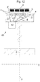
- FIG 12 illustrates another preferred alternative embodiment wherein the diameter adjustment is implemented by hydraulically deforming the rim member(s) 4 of each adjustable rim arrangement 4A.
- each of the rim members 4 i.e. the aforementioned single rim member 4 or the more than one rim members 4 together defining said circular outer rim 5
- each of the rim members 4 i.e. the aforementioned single rim member 4 or the more than one rim members 4 together defining said circular outer rim 5
- each of the rim members 4 i.e. the aforementioned single rim member 4 or the more than one rim members 4 together defining said circular outer rim 5
- each of the rim members 4 i.e. the aforementioned single rim member 4 or the more than one rim members 4 together defining said circular outer rim 5
- each of the rim members 4 i.e. the aforementioned single rim member 4 or the more than one rim members 4 together defining said circular outer rim 5
- each of the rim members 4 i.
- the pressure adjusting system 62,63 can for instance comprise a pressurizing device 62 (schematically shown), such as a hydraulic pump or a hydraulic cylinder connected by at least one fluid channel 63 with each hydraulic chamber 61 of the adjustable rim arrangement 4A.
- the pressure adjusting system 62,63 can possibly also comprise valves for controlling fluid flow and/or fluid pressure.
- the pressure adjusting system 62,63 is operable to increase the fluid pressure in each of the hydraulic chambers 61 of a rim member 4 such that the radially outer wall 4' bulges radially outwards from said rotational axis X, as well as to relieve said pressure, in particular such that the radially outer wall 4' retracts from a bulging state radially back towards said rotational axis X.
- the aforementioned plurality of hydraulic chambers 61 of a rim member 4 are preferably beside each other in direction of said rotational axis X, as illustrated in Figure 12 .
- the fluid pressures in the hydraulic chambers 61 of the rim member 4 are preferably adjustable to differ from each other.
- fluid pressures in the plurality of hydraulic chambers 61 are individually adjustable by the pressure adjusting system 62,63, i.e. the pressure adjusting system 62,63 can adjust the fluid pressure, in particular increase or relieve the fluid pressure, in each of the hydraulic chambers 61 of the rim member 4 without changing fluid pressures in the other hydraulic chambers (61) of the rim member 4.
- the pressure adjusting system 62,63 preferably comprises fluid channels 63 separately connected with the hydraulic chambers 61 of the rim member 4 for enabling adjusting the fluid pressures in the hydraulic chambers 61 of the rim member 4 to differ from each other.
- the above mentioned adjustability of the fluid pressures in the hydraulic chambers 61 of the rim member 4 to differ from each other provides an additional advantage that the profile of the rim member 4 can be adjusted to control the position of the rope 2 in direction of the rotational axis X.
- the amount of camber of the profile of the rim member 4 can be increased or decreased by which camber the rope can be guided in direction of said rotational axis X towards the peak of the convex shaped profile.
- Asymmetry of the profile of the rim member 4 relative to plane of rotation p of the drive sheave body 3 can also be increased or decreased, by which asymmetry the rope can be guided towards a desired location in direction of said rotational axis X.
- the drive sheave 1 can have a hydraulic pressurizing device 52,62 per each said adjustable rim arrangement 4A, but this is not necessary since hydraulic pressure can be shared for implementing adjustment of more than one adjustable rim arrangements 4A, particularly since it is possible to pressurize a fluid by a single pressurizing device, such as a pump or a hydraulic cylinder, and to connect the fluid with plurality of hydraulic chambers, and to use control valves between the pressurizing device and each hydraulic chamber which control valves are adjustable to reduce the fluid pressure individually.
- a single pressurizing device such as a pump or a hydraulic cylinder
- the diameter of the rim 5 of one or more of said rim arrangements 4A is individually adjustable for enlarging or reducing the turning radius of a rope 2 passing around the rim 5 in question.
- the diameter of the rim 5 of more than one, possibly all or all but one, of said plurality of rim arrangements 4A is individually adjustable for enlarging or reducing the turning radius of a rope 2 passing around the rim 5 in question.
- the drive machinery M can for instance comprise 2, 3, 4, 5, 6, 7, 8, 9 or 10 rim arrangements 4A, and the diameter of the circular outer rim 5 of all or all but one of these rim arrangements 4A is individually adjustable for enlarging or reducing the turning radius of a rope 2 passing around the circular outer rim 5 in question.
- the motor m is connected with the drive sheave body 3, preferably directly or via transmission, such that the motor m can rotate the drive sheave body 3.
- the drive sheave body 3 is preferably either directly fixed to or integral with the rotor r of the motor m. Alternatively, there could be a force transmission, such as gears, between the motor m and the drive sheave body 3.
- Said adjusting means 10,20,30,40,50,60 are preferably mounted on the drive sheave body 3 such that they are rotatable together with the drive sheave body 3 around said rotational axis X.
- said releasing (i.e. releasing of the wedging and/or the push) and making way may for a rim member 4 to move radially towards said rotational axis X may include also pulling the rim member 4 to move radially back towards said rotational axis X.
- This can be simply implemented by mechanically connecting parts to each other radially immovably or at least substantially immovably.
- this can be implemented by mechanically connecting the wedging means 11,21,31, such as the wedging member 11,21,31 thereof, radially immovably or at least substantially immovably to the rim member 4 or by mechanically connecting the screwing means, such as the screw 41c thereof, radially immovably or at least substantially immovably to the rim member 4.
- the elevator is preferably such that it comprises a tension sensing means s for sensing individual tensions of one or more of the ropes 2, and the elevator is arranged to adjust with said adjusting means 10,20,30,40,50,60 the diameter of the circular outer rim 5 of at least one adjustable rim arrangement 4A based on the sensed individual tensions 2.
- said tension sensing means can comprise a force sensor s between the elevator car c and an end of a rope 2 fixed to the elevator car c for sensing individual tension of said rope 2 and/or a force sensor between the counterweight and an end of a rope fixed to counterweight for sensing individual tension of said rope 2.
- the force sensor(s) s would preferably be between an end of a rope fixed to a stationary fixing base (e.g. stationary structure of the building) on the elevator car c side for sensing individual tension of said rope 2 and/or between an end of a rope fixed to a stationary fixing base (e.g. stationary structure of the building) on the counterweight side for sensing individual tension of said rope 2.
- a stationary fixing base e.g. stationary structure of the building
- the elevator is more particularly arranged to sense individual tensions of one or more of the ropes 2 and compare the sensed individual tensions with one or more reference tensions and to adjust by said adjusting means 10,20,30,40,50,60 the diameter of the circular outer rim 5 of at least one adjustable rim arrangement 4A based on the sensed individual tensions 2, in particular such that a difference between a measured tension and a reference tension is reduced.
- Said one or more reference tensions can comprises a preset tension or an average tension of measured individual tensions of plurality of ropes or a measured individual tension of one of the other ropes of the elevator, for example.
- the adjustable rim arrangement 4A comprises a single rim member 4 defining said circular outer rim 5.
- the one rim member 4 defining said circular outer rim 5 is deformable to have different diameters, which can be implemented by resilient material and/or structure.
- the deformability of the circular outer rim 5 to have different diameters can be facilitated structurally for instance by providing the rim member(s) of an adjustable rim arrangement 4A with plurality of cavities cv as illustrated in Figures 14a and 14b .
- the rim member 4 comprises cavities cv.
- the rim member 4 comprises plurality of cavities cv side by side in the rotational direction X distributed along the rim 5 in tangential direction thereof.
- the cavities are elongated and oriented in tangential direction of the rim 5.
Landscapes
- Engineering & Computer Science (AREA)
- Civil Engineering (AREA)
- Mechanical Engineering (AREA)
- Structural Engineering (AREA)
- Lift-Guide Devices, And Elevator Ropes And Cables (AREA)
Abstract
Description
- The invention relates to an elevator drive machinery and an elevator utilizing the drive machinery. The elevator is preferably an elevator for transporting passengers and/or goods.
- Elevators typically comprise a drive sheave and a roping comprising ropes connected with the elevator car and passing around the drive sheave. Via the ropes, traction force can be transmitted from the drive sheave to the car. Thereby, car movement can be achieved and controlled by the drive sheave. The drive sheave can be rotatable by an electric motor, for example.
- The ropes driven by the drive sheave are typically connected on one side of the drive sheave with the elevator car and on the other side with a counterweight.
- Traction sheave elevators are prone to having more or less uneven rope forces. Ideally, parallel ropes would have equal forces, but in practice rope force differences exist in the elevator due to non-idealities, such as rope thickness variation, rope stiffness variation, rope coating thickness variation or rope groove diameter variation. If there are differences in the turning diameter (e.g. the pitch diameter) of ropes of an elevator, the ropes will experience travel differences as the elevator is run. This will generate unevenness in forces of parallel ropes.
- Especially high friction ropes, such as ropes having a polymer coating, are easily subjected to large force variations due to their small slip on the drive sheave. Large rope force variations occurring on every roundtrip cause excessive fatigue loads on load bearing components, such as rope fixings, ropes themselves and guide shoes. They also cause ride comfort problems, increase pulley wear rate and reduce rope lifetime. Problems of rope force variation may also be faced with ropes engaging with positive engagement with the drive sheave.
- There are known solutions for equalizing rope tensions of individual ropes of a roping, where there are rope tension equalizers at the rope ends. Such a solution has been presented in document
FI84803B - It has been noticed that with high friction ropes, such as ropes having a polymer coating, there is little or virtually no slip between ropes and the traction sheave, so the travel differences are hardly compensated by slip unlike in the case of steel ropes. When the travel differences are not compensated, ropes having different free lengths have to be elongated to the same length between hitch plate and traction sheave. Different elongations cause uneven rope forces especially when the car or the counterweight is approaching the top of the hoistway, because in this case suspension ropes are short and their stiffness is high.
- It has also been noticed that rope travel differences are prone to accumulate with each rotation of the traction sheave. Long travel distance of the elevator, small traction sheave and 2:1 suspension increase the number of rotations of the sheave and worsen the problem. The lower is the headroom, the shorter and stiffer are the suspension ropes as the car or the counterweight is at the top of the hoistway.
- It has therefore been noticed a drawback that the ability of prior solutions to equalize tension is the most problematic in elevators which have one or more of the following: long travel distance, low amount of slip, small diameter of the traction sheave and 2:1 suspension, low head room.
- The object of the invention is to provide a solution which is improved in terms of rope tension equalization of elevator ropes to be driven by a drive machinery. An object is particularly to alleviate one or more of the above defined drawbacks of prior art and/or problems discussed or implied elsewhere in the description. Solutions are presented, inter alia, by which an elevator can be achieved which has reduced variation of tension between individual ropes. Solutions are presented, inter alia, whereby this can be achieved even though the elevator has one or plurality of the following: long travel distance, low amount of slip, small diameter of the traction sheave and 2:1 suspension, low head room.
- It is brought forward a new drive machinery for an elevator, the drive machinery comprising a rotatable drive sheave for driving plurality of ropes of the elevator, and a motor for rotating the drive sheave; the drive sheave comprising a drive sheave body rotatable around a rotational axis; and a plurality of rim arrangements mounted on the drive sheave body side by side in direction of said rotational axis, each said rim arrangement defining a circular outer rim for transmitting traction to a rope, in particular on which circular outer rim a rope can be placed to rest, said circular outer rims being coaxial with each other. The diameter of the circular outer rim of one or more of said rim arrangements is individually adjustable (i.e. without changing diameters of the rims of the other rim arrangements) for enlarging or reducing the turning radius of a rope passing around the circular outer rim in question.
- With this solution, it is possible to adjust the speed of a particular rope relative to the other ropes of the elevator by which speed the rope passes around the drive sheave from one side of it to the other side of it. With the solution described, a tension difference, such as a tension difference generated by car position change, between said particular rope and other ropes, can be eliminated.
- With this solution, one or more of the above mentioned advantages and/or objectives are achieved. Preferable further features are introduced in the following, which further features can be combined with the drive machinery individually or in any combination.
- In a preferred embodiment, the rim members of the rim arrangements are at least substantially unrotatable around the rotational axis relative to the drive sheave body.
- In a preferred embodiment, the circular outer rims of said rim arrangements are at least substantially unrotatable around the rotational axis relative to each other.
- In a preferred embodiment, the
drive sheave body 3 and the plurality of rim arrangements are connected to each other such that they are all together rotatable by the motor m around said rotational axis. - In a preferred embodiment, the individually adjustable diameter is individually adjustable to become greater relative to the diameters of the circular outer rims of the other rim arrangements and/or to become smaller relative to the diameters of the circular outer rims of the other rim arrangements.
- In a preferred embodiment, the individually adjustable diameter is individually adjustable to become greater than diameters of the circular outer rims of all the other rim arrangements and/or to become smaller than diameters of the circular outer rims of all the other rim arrangements.
- In a preferred embodiment, each said rim arrangement is suitable for transmitting traction to only one rope.
- In a preferred embodiment, said adjustability is possible during rotation of the drive sheave. That is, the diameter of the circular outer rim of one or more of said rim arrangements is individually adjustable for enlarging or reducing the turning radius of a rope passing around the circular outer rim in question during rotation of the drive sheave.
- In a preferred embodiment, each said rim arrangement comprises a single rim member defining said circular outer rim or more than one rim members together defining said circular outer rim.
- In a preferred embodiment, said drive sheave moreover comprises an adjusting means for individually adjusting (i.e. without changing diameters of the rims of the other rim arrangements) the diameter of the circular outer rim of each of the one or more adjustable rim arrangements.
- In a preferred embodiment, the motor for rotating the drive sheave is connected with the drive sheave body, preferably directly or via transmission, such that the motor can rotate the drive sheave body. The drive sheave body is preferably either directly fixed to or integral with the rotor of the motor. Alternatively, there could be a force transmission, such as gears, between the motor and the drive sheave body.
- In a preferred embodiment, said adjusting means are mounted on the drive sheave body such that they are rotatable together with the drive sheave body around said rotational axis.
- In a preferred embodiment, said adjusting means are electrically controllable. Said adjusting means are particularly preferably electrically controllable by an elevator control, which is configured to automatically control the motor for rotating the drive sheave of the machinery. Preferably, said adjusting means comprise an input for an electrical control signal. The adjusting means being electrically controllable gives freedom in selecting how the adjustment is performed as well as selecting based on which variables the adjustment is performed. An advantage is that the control of the adjusting means can be programmed to intelligently take into account any number of variables, analyze plurality of variables and compare variables freely. Preferably, control variables include rope tensions of individual ropes of the elevator.
- In a preferred embodiment, said adjusting means are suitable for changing position of the rim member(s) (i.e. the aforementioned single rim member or more than one rim members together) defining said circular outer rim of an adjustable rim arrangement in radial direction of said rotational axis or at least the position of the circular outer rim defined by the rim member(s) in radial direction of said rotational axis.
- In a preferred embodiment, the diameter adjustment is arranged to occur by aid of wedging. In a preferred embodiment, utilizing wedging, said adjusting means comprises, preferably per each said adjustable rim arrangement, a wedging means actuatable to wedge the rim member(s) (i.e. the aforementioned single rim member or more than one rim members together) defining said circular outer rim of an adjustable rim arrangement radially outwards from said rotational axis, as well as to release said wedging. Moreover, said adjusting means comprises an actuator for actuating the wedging means. Said adjusting means can comprise such an actuator per each said adjustable rim arrangement, or alternatively a shared actuator can be used for actuation of wedging means of more than one adjustable rim arrangement.
- In a preferred embodiment utilizing wedging, said wedging means comprises at least one wedging member in radial direction between the rotational axis and a rim member of an adjustable rim arrangement, which wedging member is movable relative to the rim member forward for wedging the rim member radially outwards from said rotational axis, and backwards for releasing said wedging and for making way for the rim member to move radially towards said rotational axis, and the actuator is arranged to actuate movement of the wedging member forward and backwards.
- In a preferred embodiment utilizing wedging, said wedging means comprises at least one wedging member in radial direction between the rotational axis and a rim member of an adjustable rim arrangement, which wedging member is movable relative to the rim member forward in direction of said rotational axis or in tangential direction of said rotational axis for wedging the rim member radially outwards from said rotational axis, and backwards in direction of said rotational axis or in tangential direction of said rotational axis for releasing said wedging and for making way for the rim member to move radially towards said rotational axis, and the actuator is arranged to actuate movement of the wedging member forward and backwards in direction of said rotational axis or in tangential direction of said rotational axis.
- In a preferred embodiment utilizing wedging, said wedging member has a radially (in radial direction of the rotational axis) outer side portion which is slanted and movable against a radially (in radial direction of the rotational axis) inner side portion of the rim member for wedging the rim member radially outwards from said rotational axis.
- In a preferred embodiment utilizing wedging, said rim member has a radially inner side portion which is slanted and faces the slanted radially outer side portion of the wedging member.
- In a preferred embodiment utilizing wedging, said wedging member is ring shaped and surrounds the rotational axis. Thus, it can be used to wedge the rim member(s), were it a single or an array of them, evenly and with simple structure.
- In a preferred embodiment utilizing wedging, said wedging member has a conical radially outer side.
- In a preferred embodiment utilizing wedging, the aforementioned single rim member has a conical radially inner side, or the radially inner sides of the rim members of the array together define a conical shape.
- In a preferred embodiment utilizing wedging, said actuator is an electric motor or a hydraulic cylinder.
- In a preferred embodiment utilizing wedging, said actuator is an electric motor and rotation, such as speed and/or direction thereof, of the motor is electrically controllable.
- In a preferred embodiment utilizing wedging, said actuator is connected via at least one drive member with the wedging means, in particular with a wedging member thereof.
- In a preferred embodiment utilizing wedging, said actuator is a motor, such as an electric motor for example, and rotation of the motor in one direction is arranged to move the wedging member forward in first direction of said rotational axis, and rotation of the motor in another direction i.e. the opposite direction is arranged to move the wedging member backwards in second direction of said rotational axis.
- In a preferred embodiment utilizing wedging, the wedging is caused by at least one wedging member. However, it is preferable that said adjusting means comprises two of said wedging members for acting on the same rim member. This is preferably implemented moreover such that the two wedging members have mutually opposite forward direction and backwards direction.
- In a preferred embodiment utilizing wedging, the actuator, such as a motor or a hydraulic cylinder, can move the wedging member(s) by screwing.
- In a preferred embodiment utilizing wedging, the at least one drive member comprises a screw member oriented in direction parallel with the rotational axis and the wedging member comprises an internal thread engaging with an external thread of the screw member.
- In a preferred embodiment utilizing wedging, said adjusting means comprises two of said wedging members movable by the actuator in direction of said rotational axis simultaneously towards each other both simultaneously wedging the rim member radially outwards from said rotational axis and/or in direction of said rotational axis simultaneously away from each other both simultaneously releasing said wedging and making way for the rim member to move radially towards said rotational axis.
- In a preferred embodiment utilizing wedging, each said rim member has a threaded radially inner side portion which is slanted and meshes with a threaded slanted radially outer side portion of the wedging member, and the wedging member is rotatable by the actuator relative to the rim member. The actuator can be a motor, such as an electric motor or a hydraulic cylinder for instance. However, preferably, the actuator is a hydraulic cylinder connected with the wedging means, in particular with the wedging member thereof. In this case, one of the extension and retraction of the hydraulic cylinder is arranged to rotate the wedging member relative to the rim member in one rotation direction and move it forward in direction of said rotational axis guided by the threaded engagement between the rim member and the wedging member thereby wedging the rim member radially outwards from said rotational axis. The other of the extension and retraction of the hydraulic cylinder is arranged to rotate the wedging member relative to the rim member in the other rotation direction and move the wedging member backwards in direction of said rotational axis guided by the threaded engagement between the rim member and the wedging member, thereby releasing said wedging and making way for the rim member to move radially towards said rotational axis.
- In a preferred embodiment utilizing wedging, said adjusting means comprises two of said wedging members rotatable by the actuator relative to the rim member, as mentioned in the previous paragraph, which are movable in direction of said rotational axis simultaneously towards each other both simultaneously wedging the rim member radially outwards from said rotational axis and/or simultaneously away from each other both simultaneously releasing said wedging and making way for the rim member to move radially towards said rotational axis. Particularly, the slanted and threaded radially outer side portion of each of the wedging members then meshes with a slanted and threaded radially inner side portion of a rim member of the rim arrangement.
- In a preferred embodiment, the diameter adjustment is arranged to occur by screwing. In a preferred embodiment, utilizing screwing, said adjusting means comprises, preferably per each said adjustable rim arrangement, a screwing means actuatable to push the rim member(s) (i.e. the aforementioned single rim member or more than one rim members together) defining said circular outer rim of an adjustable rim arrangement radially outwards from said rotational axis, as well as to release said push. Moreover, said adjusting means comprises an actuator for actuating the screwing means. Said adjusting means can comprise such an actuator per each said adjustable rim arrangement, or alternatively a shared actuator can be used for actuation of screwing means of more than one adjustable rim arrangement. Said actuator is preferably an electric motor. Then, preferably, rotation speed and/or rotation direction, of the motor is electrically controllable.
- In a preferred embodiment utilizing screwing, the screwing means comprises one or more screws rotatable by said actuator. Preferably, each said screw is rotatable in two rotation directions by said actuator, most preferably around an axis extending in radial direction of the rotational axis of the drive sheave body.
- In a preferred embodiment utilizing screwing, said actuator is arranged to rotate each said screw inside a threaded opening provided on the drive sheave body or an element mounted thereon in one rotation direction for pushing a rim member radially outwards from said rotational axis and in the other rotation direction for releasing said push and for making way for the rim member to move radially back towards said rotational axis of the drive sheave body.
- In a preferred embodiment utilizing screwing, each said screw is arranged to push a rim member radially outwards from said rotational axis when rotated by the actuator in one rotation direction, and to release said push and make way for the rim member to move radially back towards said rotational axis X when rotated by the actuator in the other rotation direction.
- In a preferred embodiment utilizing screwing, the actuator is arranged to rotate said one or more screws via a bevel gear mechanism.
- In a preferred embodiment utilizing screwing, the rotational axis of the (actuator) motor is parallel with said rotational axis of the drive sheave body.
- In a preferred embodiment, the diameter adjustment is arranged to occur by aid of hydraulics. In a preferred embodiment utilizing hydraulics, each of the rim member(s) (i.e. the aforementioned single rim member or more than one rim members together) defining said circular outer rim of an adjustable rim arrangement comprises at least one hydraulic chamber containing hydraulic fluid, and a radially outer wall, the radially outer wall in particular bordering the hydraulic chamber on the radially outer side thereof, the shape of which radially outer wall is elastically deformable, and the adjusting means comprises a pressure adjusting system, such as a pressure adjusting system containing a hydraulic pressurizing device (e.g. a hydraulic pump or a hydraulic cylinder), for adjusting fluid pressure, in particular increase or relieve the fluid pressure, in the hydraulic chamber, the pressure adjusting system being operable to increase the fluid pressure in the one or more hydraulic chambers such that the radially outer wall bulges radially outwards from said rotational axis, as well as to relieve said pressure, in particular such that the radially outer wall retracts from a bulging state radially back towards said rotational axis.
- In a preferred embodiment utilizing hydraulics, each of the rim member(s) (i.e. the aforementioned single rim member or more than one rim members together) defining said circular outer rim of an adjustable rim arrangement comprises plurality of hydraulic chambers containing hydraulic fluid, and a radially outer wall, the radially outer wall in particular bordering the hydraulic chamber on the radially outer side thereof, the shape of which radially outer wall is elastically deformable, and the adjusting means comprises a pressure adjusting system, such as a pressure adjusting system comprising a hydraulic pressurizing device (e.g. a hydraulic pump or a hydraulic cylinder), for adjusting fluid pressures in the hydraulic chambers, the pressure adjusting system being operable to increase the fluid pressure in each of the hydraulic chambers such that the radially outer wall bulges radially outwards from said rotational axis, as well as to relieve said pressure, in particular such that the radially outer wall retracts from a bulging state radially back towards said rotational axis. Preferably, the plurality of hydraulic chambers are beside each other in direction of said rotational axis of the drive sheave body.
- In a preferred embodiment utilizing hydraulics, the fluid pressures in the hydraulic chambers of the same rim member are adjustable to differ from each other.
- In a preferred embodiment utilizing hydraulics, the pressure adjusting system comprises fluid channels separately connected with the hydraulic chambers of the rim member for enabling adjusting the fluid pressures in the hydraulic chambers of the rim member to differ from each other.
- In a preferred embodiment utilizing hydraulics, fluid pressures in the plurality of hydraulic chambers are individually adjustable by the pressure adjusting system, i.e. the pressure adjusting system can adjust the fluid pressure, in particular increase or relieve the fluid pressure, in each of the hydraulic chambers of the rim member without changing fluid pressures in the other hydraulic chambers of the rim member.
- It is also brought forward a new elevator comprising a drive machinery as defined anywhere above, and plurality of ropes arranged to pass around the drive sheave thereof, in particular each resting on an outer rim of one of the rim arrangements of the drive sheave. With this solution, one or more of the above mentioned advantages and/or objectives are achieved. Preferable further features are introduced in the following, as well as above in context of description of the drive machinery, which further features can be combined with the elevator individually or in any combination.
- In a preferred embodiment, said rope comprises a coating forming the outer surface of the rope, wherein the coating is in contact with the outer rim of one of the rim arrangements of the drive sheave and the coating comprises polymer material.
- In a preferred embodiment, the elevator comprises a tension sensing means for sensing individual tensions of one or more of the ropes, the elevator being arranged to adjust, preferably with the aforementioned adjusting means, the diameter of the circular outer rim of at least one adjustable rim arrangement based on the sensed individual tensions of one or more of the ropes.
- In a preferred embodiment, the elevator is arranged to sense individual tensions of one or more of the ropes and compare the sensed individual tensions with one or more reference tensions and to adjust by said adjusting means the diameter of the circular outer rim of at least one adjustable rim arrangement based on the sensed individual tensions, in particular such that a difference between a measured tension and a reference tension is reduced.
- In a preferred embodiment, said reference tension can comprises a preset tension or an average tension of measured individual tensions of plurality of ropes or a measured individual tensions of one of the other ropes of the elevator, for example.
- In a preferred embodiment, the elevator comprises a hoistway, an elevator car vertically moveable in the hoistway, and an elevator control, which is configured to automatically control the motor of the machinery.
- In a preferred embodiment, the maximal travel distance of the elevator car is preferably more than 100 meters, more preferably more than 200 meters, most preferably more than 300 meters.
- In a preferred embodiment, each said rope is belt-shaped, i.e. substantially larger in width direction w than in thickness direction. The width/thickness ratio of the rope is then preferably more than 2.
- In a preferred embodiment, each said rope is a flat belt or the rope has tooth pattern engaging counterpart tooth pattern of the outer rim of a circular rim member of the drive sheave, or the rope comprises a rib pattern of ribs parallel to longitudinal direction of the rope engaging counterpart rib pattern of the outer rim of a circular rim member of the drive sheave.
- In a preferred embodiment, said adjusting means are adjusting equipment.
- The elevator is in general preferably such that it comprises an elevator car vertically movable to and from plurality of landings, i.e. two or more vertically displaced landings. Preferably, the elevator car has an interior space suitable for receiving a passenger or passengers, and the car can be provided with a door for forming a closed interior space.
- In the following, the present invention will be described in more detail by way of example and with reference to the attached drawings, in which
-
Figure 1 illustrates a drive machinery for an elevator according to a preferred embodiment. -
Figure 2 illustrates a schematically adjustability of an adjustable rim arrangement ofFigure 1 as seen in direction of the rotational axis of the drive sheave. -
Figure 3 illustrates an embodiment of an elevator implementing the drive machinery ofFigure 1 . -
Figure 4 illustrates preferred details of the rope utilized in combination with the drive machinery ofFigure 1 . -
Figures 5 and 6 illustrate different ways to form a circular outer rim of an adjustable rim arrangement ofFigure 1 . -
Figure 7 illustrates preferred details of a first kind for the drive machinery ofFigure 1 . -
Figures 8a and 8b illustrates preferred details of a second kind for the drive machinery ofFigure 1 . -
Figure 9 illustrates preferred details of a third kind for the drive machinery ofFigure 1 . -
Figure 10 illustrates preferred details of a fourth kind for the drive machinery ofFigure 1 . -
Figure 11 illustrates preferred details of a fifth kind for the drive machinery ofFigure 1 . -
Figure 12 illustrates preferred details of a sixth kind for the drive machinery ofFigure 1 . -
Figure 13 illustrates preferred details connections between parts of an elevator. -
Figures 14a and 14b illustrate preferred details for facilitating deformation of a rim member of an adjustable rim arrangement particularly to be used in an embodiment in accordance withFigure 5 . - The foregoing aspects, features and advantages of the invention will be apparent from the drawings and the detailed description related thereto.
-
Figure 1 illustrates a drive machinery M for an elevator according to a preferred embodiment. The drive machinery M comprises arotatable drive sheave 1 for driving plurality ofropes 2 of the elevator, and a motor m for rotating thedrive sheave 1. The motor m is preferably an electric motor. Thedrive sheave 1 comprises adrive sheave body 3 rotatable around a rotational axis X. Thedrive sheave 1 moreover comprises a plurality ofrim arrangements 4A mounted on thedrive sheave body 3 side by side in direction of said rotational axis X, each saidrim arrangement 4A defining a circularouter rim 5 for transmitting traction to arope 2, and on which circular outer rim 5 a rope can be placed to rest. Theouter rims 5 of therim arrangements 4A are coaxial with each other. Said rotational axis X is a rotational axis of the circularouter rims 5. - The drive machinery M is suitable for exerting traction via the
rim arrangements 4A on theropes 2 passing around them. InFigure 1 , thedrive sheave 1 is arranged to exert traction via therim arrangements 4A on theropes 2 passing around them. - The
drive sheave body 3 and the plurality ofrim arrangements 4A are connected to each other such that they are all together rotatable by the motor m around said rotational axis X. - As schematically illustrated in
Figure 2 , the diameter of therim 5 of one or more of saidrim arrangements 4A is individually (i.e. without changing diameters of therims 5 of theother rim arrangements 4A) adjustable for enlarging or reducing the turning radius of arope 2 passing around therim 5 in question. Therim arrangements 4A, the outer rim diameter of which are individually adjustable, are also referred to by using term individually adjustable rim arrangements and term adjustable rim arrangements. - Preferably, said
rim members 4 are completely or at least substantially unrotatable around the rotational axis X relative to thedrive sheave body 3. When no considerable relative rotation can occur between therim members 4 and thedrive sheave body 3, these can all be effectively rotated together. Here, by term substantially unrotatable it is meant that therim arrangements 4A in question cannot rotate around the rotational axis X relative to thedrive sheave body 3 more than 10 degrees. - Preferably, the circular
outer rims 5 of saidrim arrangements 4A are completely or at least substantially unrotatable around the rotational axis X relative to each other. When no considerable relative rotation can occur between the circularouter rims 5, rope tensions cannot be equalized effectively by relative rotation between the circularouter rims 5. In this context, the diameter adjustment is particularly advantageous. Here, by term substantially unrotatable it is meant that therim arrangements 4A in question cannot rotate around the rotational axis X relative each other more than 10 degrees. - The individually adjustable diameter is particularly individually adjustable to become greater relative to the diameters of the circular
outer rims 5 of theother rim arrangements 4A and/or to become smaller relative to the diameters of the circularouter rims 5 of theother rim arrangements 4A. It is moreover preferable that the individually adjustable diameter is individually adjustable to become greater than diameters of the circularouter rims 5 of all theother rim arrangements 4A of thedrive sheave 1 and/or to become smaller than diameters of the circularouter rims 5 of all theother rim arrangements 4A of thedrive sheave 1. Thus, the speed of arope 2 passing around the circularouter rim 5 that is in this way individually adjustable, can be made to be the highest within the roping formed by theropes 2 or the lowest within the roping formed by theropes 2. Hereby, the tension of therope 2 passing around the circularouter rim 5 in question can be affected quickly and individually. It is also preferable that the diameters of the circularouter rims 5 of theadjustable rim arrangements 4A are adjustable to become the same with each other, and preferably also the same as the diameters of the circularouter rims 5 of therim arrangements 4A the diameters of which are not adjustable, if such exist. Hereby, all the circularouter rims 5 of thedrive sheave 1 can be made to have the same diameter, which is a well working starting point for a new elevator being installed. -
Figure 2 shows how the path of therope 2 changes when the diameter of theouter rim 5 of arim arrangement 4A is changed between d1 and d2. When with a given angular speed ω, the diameter is increased from d1 to d2, the tangential speed is increased from V1 to V2. This means that the speed of therope 2 passing around theouter rim 5 in question is increased from V1 to V2. When this kind of adjustment is made for an individualouter rim 5, the speed of theindividual rope 2 passing around it is increased relative to other ropes of the system, when diameters of therims 5 around which they travel are not also increased. Correspondingly, by reduction of the diameter of theouter rim 5, the speed of therope 2 passing around it can be reduced. An advantage is that the tension values of therope 2 in question existing on opposite sides of thedrive sheave 1 can be brought towards the tension values of the other ropes existing on opposite sides of thedrive sheave 1. Thus, by individual rim diameter adjustment rope tension variations generated during car movement (e.g. due to non-idealities existing in the elevator structures) can be reduced. This alleviates tension problems in the elevator system. - In the preferred embodiment, each said
rim arrangement 4A is suitable for transmitting traction to only onerope 2. This facilitates that the tension adjustment can be focused on only one rope. -
Figure 3 illustrates a preferred embodiment of an elevator according to the invention. The elevator comprises a drive machinery M as described above and plurality ofropes 2 arranged to pass around thedrive sheave 1 thereof. - The elevator comprises a hoistway H, and an elevator car C vertically moveable in the hoistway H, and an
elevator control 100, which is configured to automatically control the motor m of the machinery M. The elevator comprises plurality ofropes 2 passing around thedrive sheave 1, each resting on anouter rim 5 of one or therim arrangements 4A of thedrive sheave 1. - The elevator moreover comprises a counterweight CW and the
ropes 2 interconnect the car C and counterweight CW. Thedrive sheave 1 engages the section of eachrope 2 extending between the car C and counterweight CW. - The maximal travel distance d of the elevator car C, that is the distance between the uppermost position and the lowermost position of the car C during elevator use to serve passengers, which are realized when the car C (in particular the sill thereof) is level with the uppermost landing (in particular the sill thereof) where the car C can be driven and when the car C (in particular the sill thereof) is level with the lowermost landing (in particular the sill thereof) where the car C can be driven, respectively, is preferably more than 100 meters, more preferably more than 200 meters, possibly more than 300 meters, because the longer the travel distance, the more advantageous the solution is.
-
Figure 4 illustrates preferred details of therope 2. In this case, therope 2 is such that it can rest on anouter rim 5 of one of therim arrangements 4A of thedrive sheave 1 such that little or virtually no slip can occur between therope 2 and theouter rim 5 of thedrive sheave 1. In the embodiment illustrated, this is due to therope 2 comprising an outer surface material comprising polymer. More specifically, in the presented embodiment, therope 2 comprisesload bearing members 9 extending in longitudinal direction of therope 2 throughout the length thereof and embedded in acoating 8 forming the outer surface of therope 2. Thecoating 8 comprises polymer material such as polyurethane for example, or alternatively rubber or silicone. Thecoating 8 is in contact with theouter rim 5 of arim member 4 of one of therim arrangements 4A of thedrive sheave 1. Therope 2 is moreover belt-shaped, i.e. substantially larger in width direction w than in thickness direction t, which increases firmness of engagement between it and thedrive sheave 1. This rope-shape thereby in its part reduces likelihood of slip between therope 2 and theouter rim 5 of thedrive sheave 1, and thereby the presented solution is advantageous with this kind ofrope 2. The belt can be a flat belt, for example. Likelihood of slip is even lower if therope 2 has tooth pattern engaging counterpart tooth pattern of theouter rim 5 of arim member 4 of thedrive sheave 1, or if therope 2 comprises a rib pattern of ribs parallel to longitudinal direction of the rope engaging counterpart rib pattern of theouter rim 5 of arim member 4 of thedrive sheave 1, said alternative and optional patterns being presented inFigure 4 inbroken lines rope 2, such as with ropes having round cross-section and comprising an outer surface material comprising polymer. The invention may be advantageous also with an uncoated steel rope passing around an uncoated drive sheave. In this kind of context, the tension differences between ropes do not tend to rise very high due to slip. However, slip may cause wear on the ropes and the drive sheave. By reducing tension differences, the invention can also be used to reduce slip and thereby increase service life of an uncoated steel rope and an uncoated drive sheave. -
Figures 5 and 6 illustrates different ways to form the circularouter rim 5. These Figures each discloses schematically how said adjusting means 10,20,30,40,40,50,60 are suitable for changing position of the rim member(s) 4 or at least the position of the circularouter rim 5 defined by it/them in radial direction of said rotational axis X. These Figures each discloses a schematic cross sectional view of the parts of arim arrangement 4A defining the circularouter rim 5. In the solution presented inFigure 5 , therim arrangement 4A comprises a single rim member defining said circularouter rim 5. In this case, the onerim member 4 defining said circularouter rim 5 is deformable to have different diameters, which can be implemented by resilient material and/or structure. The change of diameter need not be necessarily large in the adjustment, so even slight deformability of therim member 4 can be sufficient, depending on the case. The material can be some composite material or plastic material, for instance. Anyway, should the material of therim member 4 be of a very rigid material such as metal, the structure is preferable to design to have thin material thickness such that the deformation is achievable without very high forces and without departing from elastic nature of the deformation. In the solution presented inFigure 6 , therim arrangement 4A comprises more than onerim members 4 defining together said circularouter rim 5. In this case plurality ofrim members 4 together form an array ofrim members 4 each defining a segment of said circularouter rim 5 for transmitting traction to arope 2. In the embodiment ofFigure 6 , therim members 4 do not need to be deformable. - For the purpose of carrying out the adjusting of the diameters of the
rims 5 of theadjustable rim arrangements 4A, saiddrive sheave 1 moreover comprises an adjusting means 10,20,30,40,50,60 for individually adjusting the diameter of the circularouter rim 5 of each of theadjustable rim arrangements 4A. - Said adjusting means 10,20,30,40,50,60 are preferably electrically controllable. Said adjusting means are particularly preferably electrically controllable by an elevator control, which is configured to automatically control the motor for rotating the drive sheave of the machinery. For this purpose, said adjusting means 10,20,30,40,50,60 comprise one or more inputs i for an electrical control signal. An
elevator control 100 is illustrated inFigures 3 and10 . -
Figures 7-9 illustrate preferred alternative embodiments for implementing the diameter adjustment by aid of wedging. In these embodiments, said adjusting means 10,20,30 comprises a wedging means 11,21,31 actuatable to wedge the rim members 4 (i.e. the aforementionedsingle rim member 4 or more than onerim members 4, which alone or together define said circular outer rim 5) of anadjustable rim arrangement 4A radially outwards from said rotational axis X, as well as to release said wedging, and anactuator adjustable rim arrangement 4A. - In the embodiments of
Figures 7-9 , said wedging means 11,21,31 comprises a wedgingmember rim member 4 of anadjustable rim arrangement 4A, which wedgingmember rim member 4 forward F for wedging therim member 4 radially outwards from said rotational axis X, and backwards B for releasing said wedging and for making way for therim member 4 to move radially towards said rotational axis X, and theactuator member Figures 7 and8 , said movement forward and backwards is oriented parallel with direction of said rotational axis X, and in the embodiment ofFigure 9 in tangential direction of said rotational axis X. - In the embodiments of
Figures 7- 9 said wedgingmember member rim member 4 for wedging therim member 4 radially outwards from said rotational axis X. - In the embodiments of
Figures 7 and8a-8b , saidrim member 4 has a radially inner side portion which faces the slanted radially outer side portion of the wedgingmember - Said wedging
member rim members 4, were there a single or an array of them (cf.Figures 5 and 6 ), evenly and with simple structure. - In the embodiment of
Figures 7 and8a-8b , said wedgingmember rim member 4 has a conical radially inner side, or the radially inner sides of therim members 4 of the array, as described referring toFigure 6 , together define a conical shape. - In the embodiment of
Figures 7 and8a-8b , the above described wedging can be caused by at least one wedgingmember members rim member 4. This is preferably implemented moreover such that the two wedgingmembers Figures 7 and8a-8b , the wedging is arranged to be caused by moving the two wedgingmembers members - In the embodiment of
Figure 7 , saidactuator 12 is a motor. Most preferably the motor is an electric motor, and rotation, preferably rotation speed and/or rotation direction, of themotor 12 is electrically controllable. - The
actuator 12, which is here a motor, is connected via at least onedrive member 13 with the wedging means 11, in particular with a wedgingmember 11 thereof. Rotation of themotor 12 in one direction is arranged to move the wedgingmember 12 forward F in direction of said rotation axis X, and rotation of the motor in another direction (i,e. the direction opposite to said one direction) is arranged to move the wedgingmember 11 backwards B in direction of said rotational axis X. - In the embodiment of
Figure 7 , theactuator 12, i.e. themotor 12 can move the wedgingmember 11 by screwing. For this purpose, the aforementioned at least one drive member comprises ascrew member 13 oriented in direction parallel with the rotation axis X, and the wedgingmember 11 comprises an internal thread engaging with an external thread of thescrew member 13. - In the embodiment of
Figure 7 , the adjustment is implemented using two wedgingmembers 11. Particularly, said adjusting means 10 comprises two of said wedgingmembers 11 movable by theactuator 12 in direction of said rotational axis X simultaneously towards each other both simultaneously wedging therim member 4 radially outwards from said rotational axis X and/or in direction of said rotational axis X simultaneously away from each other both simultaneously releasing said wedging and making way for therim member 4 to move radially towards said rotational axis X. - The slanted outer side portion of each of the wedging
members 11 faces a slanted radially inner side of arim member 4 of theadjustable rim arrangement 4A, and slanted portions of therim members 4 acted on by the two wedgingmembers 11 are mirror shaped with respect to the plane of rotation p of the drive sheave body 3 (the plane p in Figures to which the axis X is normal). - In the embodiment illustrated, the two wedging
members 11 share a drive member, which is in the presented case ascrew member 13 extending through them, and each of said two wedgingmembers 11 comprises an internal thread engaging with an external thread of thescrew member 13. The internal threads of the two wedgingmembers 11 and the external threads of thescrew member 13 are mirror shaped with respect to the plane of rotation p of thedrive sheave body 3. Thus, by rotation of thescrew member 13 in one rotation direction, the two wedgingmembers 11 move towards each other (each moving in direction F), and by rotation of thescrew member 13 in the other rotation direction, the two wedgingmembers 11 move away from each other (each moving in direction B).Actuator 12 can be immovably mounted on thedrive sheave body 3, for instance. It is however possible to mount it alternatively immovably on the wedging member 11 (either one in Figures), in which case thescrew member 13 need not be in threaded engagement with both of the two wedgingmembers 11. - In the embodiment of
Figure 7 , thedrive sheave 1 moreover comprises a blocking means 14a,14b for blocking relative rotation between the wedgingmember 11 and thecircular rim member 4. In the illustrated embodiment, these blocking means 14a,14b comprise a blockingmember 14a placed in a nest formed between the wedgingmember 11 and therim member 4. Thenest 14b is larger than the blockingmember 14a for allowing relative movement between the wedgingmember 11 and therim member 4 in direction of said rotational axis x in said wedging. Thus the blockingmember 14a does not block the relative movement between the wedgingmember 11 and therim member 4 in direction of said rotational axis x in said wedging. - In the embodiment illustrated in
Figures 8a and 8b , therim member 4 of theadjustable rim arrangement 4A has a threaded radially inner side portion which is slanted and meshes with a threaded slanted radially outer side portion of the wedgingmember 21, and the wedgingmember 21 is rotatable by theactuator 22 relative to therim member 4. - In the embodiment illustrated in
Figures 8a and 8b , theactuator 22 is a hydraulic cylinder connected with the wedging means 21, in particular with the wedgingmember 21 thereof. One of the extension and retraction of thehydraulic cylinder 22 is arranged to rotate the wedgingmember 21 relative to therim member 4 in one rotation direction and move it forward F in direction of said rotational axis X guided by the threaded engagement between therim member 4 and the wedgingmember 21 thereby wedging therim member 4 radially outwards from said rotational axis X. The other of the extension and retraction of thehydraulic cylinder 22 is arranged to rotate the wedgingmember 21 relative to therim member 4 in the other rotation direction and move the wedgingmember 21 backwards B in direction of said rotational axis X guided by the threaded engagement between therim member 4 and the wedgingmember 21, thereby releasing said wedging and making way for therim member 4 to move radially towards said rotational axis X. Relative rotation between the wedgingmember 21 and therim member 4 could alternatively be implemented using a motor, such as an electric motor as described referring toFigure 7 . - In the embodiment of
Figures 8a-8b , theactuator 22, i.e. thehydraulic cylinder 22 can move the wedgingmember 23 by screwing. In the embodiment illustrated inFigures 8a and 8b , the adjustment is implemented using two wedgingmembers 21. Particularly, said adjusting means 20 comprises two of said wedgingmembers 21 rotatable by theactuator 22 relative to therim member 4, and movable in direction of said rotational axis X simultaneously towards each other both simultaneously wedging therim member 4 radially outwards from said rotational axis X and/or simultaneously away from each other both simultaneously releasing said wedging and making way for therim member 4 to move radially towards said rotational axis X. The slanted and threaded radially outer side portion of each of the wedgingmembers 21 then meshes with a slanted and threaded radially inner side portion of arim member 4 of the adjustable rim arrangement 4a. These two wedging members 21 (including the threads and slanting shape) and parts of therim member 4 that they contact (including the threads and slanting shape of the rim member), are then mirror shaped with respect to the rotation plane of the drive sheave body 3 (the plane p inFigure 8a to which the axis X is normal), which also parallel to the rotation planes of the wedgingmembers 21. Thereby, when the two wedgingmembers 21 are rotated together in one direction relative to therim member 4, they are at the same time screwed along the threads of therim member 4 such that they move towards each other (each moving in direction F), and when they are rotated relative to therim member 4 together in the other direction they are screwed along the threads of therim member 4 such that they move away each other (each moving in direction B). Theactuator 22 is preferably immovably or at least substantially immovably mounted on thedrive sheave body 3. - In the embodiment illustrated in
Figures 8a and 8b , thedrive sheave 1 moreover comprises a synchronizing means 24a, preferably at least one synchronizingmember 24a, for synchronizing rotation of the aforementioned two wedgingmembers 21. It is arranged to allow relative movement between the two wedgingmembers 21 in direction of said rotational axis X and block relative rotation between the wedgingmembers 21. The synchronizingmember 24a can be for instance a bar oriented parallel with rotational axis X its one end extending in a hole formed in one of the two wedgingmembers 21 and its other end extending in a hole formed in the other one of the two wedgingmembers 21, wherein said hole is also oriented parallel with the rotational axis X. - In the embodiment
Figure 9 , the wedgingmember 31 has plurality of radially (i.e. in radial direction of the rotational axis X) outer side portions which are slanted, in particular to have a first end and a second end displaced in tangential direction of the rotational axis X, which ends are at different distances from the rotational axis X, said wedgingmember 31 being movable against a radially (i.e. in radial direction of the rotational axis X) inner side of therim member 4 for wedging therim member 4 radially outwards from said rotational axis X. - In
Figure 9 , the structure when in line withFigure 5 has been shown. By broken lines the seams betweenconsecutive rim members 4 have been drawn to illustrate the structure when in line withFigure 6 . - The aforementioned
single rim member 4 or therim members 4 of the array together (as described referring toFigure 6 ) of the adjustable rim arrangement 4a comprise(s) plurality of radially inner side portions which face the slanted radially outer side portion of the wedgingmember 31 and are also slanted, in particular to have a first end and a second end displaced in tangential direction of the rotational axis X, which ends are at a different distances from the rotational axis X. - The wedging
member 31 is movable relative to therim member 4 or therim members 4 of the array in tangential direction of said rotational axis X forward F for wedging the rim member(s) 4 radially outwards from said rotational axis X, and backwards B for releasing said wedging and for making way for therim member 4 to move radially towards said rotational axis X, and theactuator 32 is arranged to actuate movement of the wedgingmember 31 in forward and backwards direction F,B. In the preferred embodiment, saidactuator 32 is a hydraulic cylinder connected with the wedgingmember 31 and the drive sheave body. Theaforementioned rim member 4 or therim members 4 of the array are completely or at least substantially unrotatable around the rotational axis X relative to thedrive sheave body 3, whereby relative movement can be ensured. - One of the extension and retraction of the
hydraulic cylinder 32 is arranged to rotate the wedgingmember 31 relative to each saidrim member 4 in one rotation direction and move it forward F in tangential direction of said rotational axis X thereby wedging each saidrim member 4 radially outwards from said rotational axis X. The other of the extension and retraction of thehydraulic cylinder 32 is arranged to rotate the wedgingmember 31 relative to each saidrim member 4 in the other rotation direction and move the wedgingmember 31 backwards B in direction of said rotational axis X thereby releasing said wedging and making way for each saidrim member 4 to move radially towards said rotational axis X. Relative rotation between the wedgingmember 31 and therim member 4 or the array of them around the rotational axis could alternatively be implemented using a motor, such as an electric motor as described referring toFigure 7 . -
Figure 10 illustrates a preferred alternative embodiment wherein the diameter adjustment is implemented by screwing. In this embodiment, the adjusting means 40 comprises, preferably per each saidadjustable rim arrangement 4A, a screwing means 41a-41d actuatable to push therim members 4 of theadjustable rim arrangement 4A (i.e. the the aforementionedsingle rim member 4 or more than onerim members 4 together defining said circularouter rim 5 of theadjustable rim arrangement 4A) radially outwards from said rotational axis X. The screwing means 41a-41d actuatable are moreover actuatable to release said push. The adjusting means 40 moreover comprises anactuator 42 for actuating the screwing means 41a-41d. - In the drive machinery M of
Figure 10 , theactuator 42 is preferably an electric motor, and rotation, preferably rotation speed and/or rotation direction, of themotor 42 is electrically controllable. Theactuator 42 is illustrated inFigure 10 with broken line. Theactuator 42 is preferably fixedly mounted on thedrive sheave body 3. - In the drive machinery M of
Figure 10 , the screwing means 41a-41d comprisesscrews 41c rotatable by saidactuator 42. Each saidscrew 41c is rotatable in two rotation directions by saidactuator 42 around an axis a extending in radial direction of the rotational axis X. The axis a has been illustrated only for one of thescrews 41c. The rotational axis of themotor 42 is parallel with said rotational axis X. Theactuator 42 is arranged to rotate each of saidscrews 41c via abevel gear mechanism - Each said
screw 41c is arranged to push arim member 4 radially outwards from said rotational axis X when rotated by the actuator in one rotation direction, and to release said push and make way for therim member 4 to move radially back towards said rotational axis X when rotated by the actuator in the other rotation direction. - Said
actuator 42 is arranged to rotate each saidscrew 41c inside a threadedopening 41d provided on thedrive sheave body 3, or alternatively an element mounted fixedly thereon, in one rotation direction for pushing arim member 4 radially outwards from said rotational axis X, and in the other rotation direction for releasing said push and for making way for therim member 4 to move radially back towards said rotational axis X. Said releasing and making way may include also pulling therim member 4 to move radially back towards said rotational axis X. -
Figure 11 illustrates a preferred alternative embodiment wherein the diameter adjustment is implemented by hydraulically deforming the rim member(s) of eachadjustable rim arrangement 4A. In this embodiment, each of the rim members 4 (i.e. the aforementionedsingle rim member 4 or the aforementioned more than onerim members 4 together defining said circularouter rim 5 of anadjustable rim arrangement 4A) comprises ahydraulic chamber 51 containinghydraulic fluid 54, and a radially outer wall 4' of the hydraulic chamber, the radially outer wall 4' in particular bordering thehydraulic chamber 51 on the radially outer side thereof, the shape of which radially outer wall 4' is elastically deformable. The adjusting means 50 comprises apressure adjusting system hydraulic chamber 51 of therim member 4. Thepressure adjusting system fluid channel 53 with eachhydraulic chamber 51 of theadjustable rim arrangement 4A. Thepressure adjusting system - The
pressure adjusting system hydraulic chamber 51 such that the radially outer wall 4' bulges radially outwards from said rotational axis X, as well as to relieve said pressure, in particular such that the radially outer wall 4' retracts from a bulging state radially back towards said rotational axis X. -
Figure 12 illustrates another preferred alternative embodiment wherein the diameter adjustment is implemented by hydraulically deforming the rim member(s) 4 of eachadjustable rim arrangement 4A. In this embodiment, each of the rim members 4 (i.e. the aforementionedsingle rim member 4 or the more than onerim members 4 together defining said circular outer rim 5) of anadjustable rim arrangement 4A comprises plurality ofhydraulic chambers 61 containinghydraulic fluid 64, and a radially outer wall 4' of the hydraulic chamber, the radially outer wall 4' in particular bordering thehydraulic chambers 61 on the radially outer side thereof, the shape of which radially outer wall 4' is elastically deformable, and apressure adjusting system hydraulic chambers 61 of therim member 4 of theadjustable rim arrangement 4A. Thepressure adjusting system fluid channel 63 with eachhydraulic chamber 61 of theadjustable rim arrangement 4A. Thepressure adjusting system - The
pressure adjusting system hydraulic chambers 61 of arim member 4 such that the radially outer wall 4' bulges radially outwards from said rotational axis X, as well as to relieve said pressure, in particular such that the radially outer wall 4' retracts from a bulging state radially back towards said rotational axis X. - The aforementioned plurality of
hydraulic chambers 61 of arim member 4 are preferably beside each other in direction of said rotational axis X, as illustrated inFigure 12 . - The fluid pressures in the
hydraulic chambers 61 of therim member 4 are preferably adjustable to differ from each other. - For facilitating adjustability of the fluid pressures in the
hydraulic chambers 61 of therim member 4 to differ from each other, in the preferred embodiment, fluid pressures in the plurality ofhydraulic chambers 61 are individually adjustable by thepressure adjusting system pressure adjusting system hydraulic chambers 61 of therim member 4 without changing fluid pressures in the other hydraulic chambers (61) of therim member 4. - For facilitating adjustability of the fluid pressures in the
hydraulic chambers 61 of therim member 4 to differ from each other, in the preferred thepressure adjusting system fluid channels 63 separately connected with thehydraulic chambers 61 of therim member 4 for enabling adjusting the fluid pressures in thehydraulic chambers 61 of therim member 4 to differ from each other. - The above mentioned adjustability of the fluid pressures in the
hydraulic chambers 61 of therim member 4 to differ from each other provides an additional advantage that the profile of therim member 4 can be adjusted to control the position of therope 2 in direction of the rotational axis X. The amount of camber of the profile of therim member 4 can be increased or decreased by which camber the rope can be guided in direction of said rotational axis X towards the peak of the convex shaped profile. Asymmetry of the profile of therim member 4 relative to plane of rotation p of thedrive sheave body 3 can also be increased or decreased, by which asymmetry the rope can be guided towards a desired location in direction of said rotational axis X. - In the embodiments of
Figures 11 and12 , thedrive sheave 1 can have ahydraulic pressurizing device adjustable rim arrangement 4A, but this is not necessary since hydraulic pressure can be shared for implementing adjustment of more than oneadjustable rim arrangements 4A, particularly since it is possible to pressurize a fluid by a single pressurizing device, such as a pump or a hydraulic cylinder, and to connect the fluid with plurality of hydraulic chambers, and to use control valves between the pressurizing device and each hydraulic chamber which control valves are adjustable to reduce the fluid pressure individually. - As mentioned above, the diameter of the
rim 5 of one or more of saidrim arrangements 4A is individually adjustable for enlarging or reducing the turning radius of arope 2 passing around therim 5 in question. Most preferably, the diameter of therim 5 of more than one, possibly all or all but one, of said plurality ofrim arrangements 4A is individually adjustable for enlarging or reducing the turning radius of arope 2 passing around therim 5 in question. The drive machinery M can for instance comprise 2, 3, 4, 5, 6, 7, 8, 9 or 10rim arrangements 4A, and the diameter of the circularouter rim 5 of all or all but one of theserim arrangements 4A is individually adjustable for enlarging or reducing the turning radius of arope 2 passing around the circularouter rim 5 in question. - In the preferred embodiments, the motor m is connected with the
drive sheave body 3, preferably directly or via transmission, such that the motor m can rotate thedrive sheave body 3. Thedrive sheave body 3 is preferably either directly fixed to or integral with the rotor r of the motor m. Alternatively, there could be a force transmission, such as gears, between the motor m and thedrive sheave body 3. Said adjusting means 10,20,30,40,50,60 are preferably mounted on thedrive sheave body 3 such that they are rotatable together with thedrive sheave body 3 around said rotational axis X. - Generally, said releasing (i.e. releasing of the wedging and/or the push) and making way may for a
rim member 4 to move radially towards said rotational axis X may include also pulling therim member 4 to move radially back towards said rotational axis X. This can be simply implemented by mechanically connecting parts to each other radially immovably or at least substantially immovably. For example, this can be implemented by mechanically connecting the wedging means 11,21,31, such as the wedgingmember rim member 4 or by mechanically connecting the screwing means, such as thescrew 41c thereof, radially immovably or at least substantially immovably to therim member 4. - The elevator is preferably such that it comprises a tension sensing means s for sensing individual tensions of one or more of the
ropes 2, and the elevator is arranged to adjust with said adjusting means 10,20,30,40,50,60 the diameter of the circularouter rim 5 of at least oneadjustable rim arrangement 4A based on the sensedindividual tensions 2. As illustrated inFigure 3 said tension sensing means can comprise a force sensor s between the elevator car c and an end of arope 2 fixed to the elevator car c for sensing individual tension of saidrope 2 and/or a force sensor between the counterweight and an end of a rope fixed to counterweight for sensing individual tension of saidrope 2. In a 2:1 solution, the force sensor(s) s would preferably be between an end of a rope fixed to a stationary fixing base (e.g. stationary structure of the building) on the elevator car c side for sensing individual tension of saidrope 2 and/or between an end of a rope fixed to a stationary fixing base (e.g. stationary structure of the building) on the counterweight side for sensing individual tension of saidrope 2. There are of course also alternative ways to measure tension of an individual rope. - Preferably, the elevator is more particularly arranged to sense individual tensions of one or more of the
ropes 2 and compare the sensed individual tensions with one or more reference tensions and to adjust by said adjusting means 10,20,30,40,50,60 the diameter of the circularouter rim 5 of at least oneadjustable rim arrangement 4A based on the sensedindividual tensions 2, in particular such that a difference between a measured tension and a reference tension is reduced. - Said one or more reference tensions can comprises a preset tension or an average tension of measured individual tensions of plurality of ropes or a measured individual tension of one of the other ropes of the elevator, for example.
- As earlier above mentioned, in the solution presented in
Figure 5 , theadjustable rim arrangement 4A comprises asingle rim member 4 defining said circularouter rim 5. In this case, the onerim member 4 defining said circularouter rim 5 is deformable to have different diameters, which can be implemented by resilient material and/or structure. The deformability of the circularouter rim 5 to have different diameters can be facilitated structurally for instance by providing the rim member(s) of anadjustable rim arrangement 4A with plurality of cavities cv as illustrated inFigures 14a and 14b . In these Figures, preferred although not necessary further features are presented, namely that therim member 4 comprises cavities cv. In the presented case, therim member 4 comprises plurality of cavities cv side by side in the rotational direction X distributed along therim 5 in tangential direction thereof. In the presented case, the cavities are elongated and oriented in tangential direction of therim 5. - It is to be understood that the above description and the accompanying Figures are only intended to teach the best way known to the inventors to make and use the invention. It will be apparent to a person skilled in the art that the inventive concept can be implemented in various ways. The above-described embodiments of the invention may thus be modified or varied, without departing from the invention, as appreciated by those skilled in the art in light of the above teachings. It is therefore to be understood that the invention and its embodiments are not limited to the examples described above but may vary within the scope of the claims.
Claims (17)
- A drive machinery (M) for an elevator, the drive machinery (M) comprising a rotatable drive sheave (1) for driving plurality of ropes (2) of the elevator, and a motor (m) for rotating the drive sheave (1); the drive sheave (1) comprisinga drive sheave body (3) rotatable around a rotational axis (X);plurality of rim arrangements (4A) mounted on the drive sheave body (3) side by side in direction of said rotational axis (X), each said rim arrangement (4A) defining a circular outer rim (5) for transmitting traction to a rope (2), said circular outer rims (5) being coaxial with each other,characterized in that the diameter (dl,d2) of the circular outer rim (5) of one or more of said rim arrangements (4A) is individually adjustable for enlarging or reducing the turning radius of a rope (2) passing around the circular outer rim (5) in question.
- A drive machinery (M) according to claim 1, wherein the individually adjustable diameter (d1,d2) is individually adjustable to become greater relative to the diameters of the circular outer rims (5) of the other rim arrangements (4A) and/or to become smaller relative to the diameters of the rims (5) of the other rim arrangements (4A).
- A drive machinery (M) according to any of the preceding claims, wherein each said rim arrangement (4A) comprises a single rim member (4) defining said circular outer rim (5) or more than one rim members (4) together defining said circular outer rim (5).
- A drive machinery (M) according to claim any of the preceding claims, wherein said drive sheave (1) comprises an adjusting means (10,20,30,40,50,60) for individually adjusting the diameter of the circular outer rim (5) of each of the adjustable rim arrangements (4A).
- A drive machinery (M) according to claim 4, wherein said adjusting means (10,20,30,40,50,60) are mounted on the drive sheave body (3) such that they are rotatable together with the drive sheave body (3) around said rotational axis (X).
- A drive machinery (M) according to any of the preceding claims 4-5, wherein said adjusting means (10,20,30,40,50,60) are electrically controllable.
- A drive machinery (M) according to any of the preceding claims 4-6, wherein said adjusting means (10,20,30,40,40,50,60) are suitable for changing position of the rim member(s) (4) defining said circular outer rim (5) of an adjustable rim arrangement (4A) in radial direction of said rotational axis (X) or at least the position of the circular outer rim (5) defined by the rim member(s) (4) in radial direction of said rotational axis (X).
- A drive machinery (M) according to any of the preceding claims 4-7, wherein said adjusting means (10,20,30) comprises
a wedging means (11,21,31) actuatable to wedge the rim member(s) (4) defining said circular outer rim (5) of an adjustable rim arrangement (4A) radially outwards from said rotational axis (X), as well as to release said wedging; and
an actuator (12,22,32) for actuating the wedging means (11,21,31). - A drive machinery (M) according to claim 8, wherein said wedging means (11,21,31) comprises at least one wedging member (11,21,31) in radial direction between the rotational axis (X) and a rim member (4) of an adjustable rim arrangement (4A), which wedging member (11,21,31) is movable relative to the rim member (4) forward (F) for wedging the rim member (4) radially outwards from said rotational axis (X), and backwards (B) for releasing said wedging and for making way for the rim member (4) to move radially towards said rotational axis (X), and the actuator (12,22,32) is arranged to actuate movement of the wedging member (11,21,31) forward (F) and backwards (B).
- A drive machinery (M) according to any of the preceding claims 8-9, wherein said actuator (12,22,32) is an electric motor (12) or a hydraulic cylinder (22,32).
- A drive machinery (M) according to any of the preceding claims 8-10, wherein said actuator (12,22) is a motor and rotation of the motor in one direction is arranged to move the wedging member (11,21) forward (F) in first direction of said rotational axis (X), and rotation of the motor in another direction i,e. the opposite direction, is arranged to move the wedging member (11,21) backwards (B) in second direction of said rotational axis (X).
- A drive machinery (M) according to any of the preceding claims 8-11, wherein said adjusting means (10) comprises two of said wedging members (11) movable by the actuator (12) in direction of said rotational axis (X) simultaneously towards each other both simultaneously wedging a rim member (4) radially outwards from said rotational axis (X) and/or in direction of said rotational axis (X) simultaneously away from each other both simultaneously releasing said wedging and making way for a rim member (4) to move radially towards said rotational axis (X).
- A drive machinery (M) according to any of the preceding claims 8-12, wherein each said rim member (4) has a threaded radially inner side portion which is slanted and meshes with a threaded slanted radially outer side portion of the wedging member (21), and the wedging member (21) is rotatable by the actuator (22) relative to the rim member (4).
- A drive machinery (M) according to any of the preceding claims 4-7, wherein said adjusting means (40) comprises
a screwing means (41a-41d) actuatable to push the rim member(s) (4) defining said circular outer rim (5) of an adjustable rim arrangement (4A) radially outwards from said rotational axis (X), as well as to release said push; and
an actuator (42) for actuating the screwing means (41a-41d). - A drive machinery (M) according to any of the preceding claims 4-7, wherein each of the rim member(s) (4) defining said circular outer rim (5) of an adjustable rim arrangement (4A) comprises at least one hydraulic chamber (51,61) containing hydraulic fluid (54,64), and a radially outer wall (4'), the radially outer wall (4') in particular bordering the hydraulic chamber (51) on the radially outer side thereof, the shape of which radially outer wall (4') is elastically deformable, and the adjusting means (50) comprises a pressure adjusting system (52,53,62,63), such as a pressure adjusting system comprising a pressurizing device (52,62), for adjusting fluid pressure in the hydraulic chamber (51,61), the pressure adjusting system (52,53,62,63) being operable to increase fluid pressure in the at least one hydraulic chamber (51,61) such that the radially outer wall (4') bulges radially outwards from said rotational axis (X), as well as to relieve said pressure, in particular such that the radially outer wall (4') retracts from a bulging state radially back towards said rotational axis (X).
- An elevator comprising a drive machinery (M) as defined in any of the preceding claims 1-15, and plurality of ropes (2) arranged to pass around the drive sheave (1) thereof, in particular each resting on a circular outer rim (5) of one of the rim arrangements (4A) of the drive sheave (1).
- An elevator according to claim 16, wherein the elevator comprises a tension sensing means (s) for sensing individual tensions of one or more of the ropes (2), the elevator being arranged to adjust, in particular with an adjusting means (10,20,30,40,50,60), the diameter of the circular outer rim (5) of at least one adjustable rim arrangement (4A) based on the sensed individual tensions (2).
Priority Applications (3)
| Application Number | Priority Date | Filing Date | Title |
|---|---|---|---|
| EP18192683.3A EP3620420B1 (en) | 2018-09-05 | 2018-09-05 | Elevator drive machinery and elevator |
| US16/458,700 US11345574B2 (en) | 2018-09-05 | 2019-07-01 | Elevator drive machinery and elevator |
| CN201910729906.XA CN110877848B (en) | 2018-09-05 | 2019-08-08 | Elevator driving mechanism and elevator |
Applications Claiming Priority (1)
| Application Number | Priority Date | Filing Date | Title |
|---|---|---|---|
| EP18192683.3A EP3620420B1 (en) | 2018-09-05 | 2018-09-05 | Elevator drive machinery and elevator |
Publications (2)
| Publication Number | Publication Date |
|---|---|
| EP3620420A1 true EP3620420A1 (en) | 2020-03-11 |
| EP3620420B1 EP3620420B1 (en) | 2021-10-27 |
Family
ID=63517742
Family Applications (1)
| Application Number | Title | Priority Date | Filing Date |
|---|---|---|---|
| EP18192683.3A Active EP3620420B1 (en) | 2018-09-05 | 2018-09-05 | Elevator drive machinery and elevator |
Country Status (3)
| Country | Link |
|---|---|
| US (1) | US11345574B2 (en) |
| EP (1) | EP3620420B1 (en) |
| CN (1) | CN110877848B (en) |
Families Citing this family (4)
| Publication number | Priority date | Publication date | Assignee | Title |
|---|---|---|---|---|
| EP3885302A1 (en) * | 2020-03-26 | 2021-09-29 | KONE Corporation | Rope wheel, traction wheel, elevator drive machinery and elevator |
| WO2023012865A1 (en) * | 2021-08-02 | 2023-02-09 | 三菱電機株式会社 | Elevator sheave |
| CN115432533A (en) * | 2022-09-14 | 2022-12-06 | 日立电梯(上海)有限公司 | Elevator anti-rolling control method and system, elevator and storage medium |
| US12043518B1 (en) * | 2023-07-28 | 2024-07-23 | Tk Elevator Innovation And Operations Gmbh | Tension equalizing traction sheave assembly for elevator assemblies |
Citations (5)
| Publication number | Priority date | Publication date | Assignee | Title |
|---|---|---|---|---|
| US185276A (en) * | 1876-12-12 | Improvement in hoisting apparatus | ||
| DE859362C (en) * | 1949-01-01 | 1952-12-15 | Eisen & Stahlind Ag | Device for load balancing in case of lower rope conveyance |
| FI84803B (en) | 1989-10-18 | 1991-10-15 | Kone Oy | Device for equalizing the forces in adjoining lift cables |
| WO2016096726A1 (en) * | 2014-12-19 | 2016-06-23 | Inventio Ag | Pulley for elevators |
| JP2017197300A (en) * | 2016-04-25 | 2017-11-02 | 三菱電機株式会社 | Elevator sheave uneven wear automatic adjustment device |
Family Cites Families (8)
| Publication number | Priority date | Publication date | Assignee | Title |
|---|---|---|---|---|
| ES2262368T5 (en) * | 1998-12-22 | 2011-10-28 | Otis Elevator Company | TENSION ELEMENT FOR AN ELEVATOR. |
| JP4558336B2 (en) * | 2004-01-20 | 2010-10-06 | 三菱電機株式会社 | Elevator drive device |
| CN201092501Y (en) * | 2007-06-13 | 2008-07-30 | 张卫华 | Elevator traction cable wire tension automatic balancer |
| FI125268B (en) * | 2010-03-11 | 2015-08-14 | Kone Corp | Drive disk lift and method for improving the frictional grip of the lens tracks of a drive disk in an elevator |
| CN103562121B (en) * | 2011-04-22 | 2016-04-13 | 伊特里克有限责任公司 | Two reel towing capstan |
| CN203392684U (en) * | 2013-07-22 | 2014-01-15 | 西子奥的斯电梯有限公司 | Novel stretching device |
| EP2990370B1 (en) * | 2014-09-01 | 2017-06-14 | KONE Corporation | Elevator |
| CN105173975A (en) * | 2015-09-27 | 2015-12-23 | 洛阳矿山机械工程设计研究院有限责任公司 | Synchronous head sheave balance adjustment method for multi-rope winding type elevator |
-
2018
- 2018-09-05 EP EP18192683.3A patent/EP3620420B1/en active Active
-
2019
- 2019-07-01 US US16/458,700 patent/US11345574B2/en active Active
- 2019-08-08 CN CN201910729906.XA patent/CN110877848B/en active Active
Patent Citations (5)
| Publication number | Priority date | Publication date | Assignee | Title |
|---|---|---|---|---|
| US185276A (en) * | 1876-12-12 | Improvement in hoisting apparatus | ||
| DE859362C (en) * | 1949-01-01 | 1952-12-15 | Eisen & Stahlind Ag | Device for load balancing in case of lower rope conveyance |
| FI84803B (en) | 1989-10-18 | 1991-10-15 | Kone Oy | Device for equalizing the forces in adjoining lift cables |
| WO2016096726A1 (en) * | 2014-12-19 | 2016-06-23 | Inventio Ag | Pulley for elevators |
| JP2017197300A (en) * | 2016-04-25 | 2017-11-02 | 三菱電機株式会社 | Elevator sheave uneven wear automatic adjustment device |
Also Published As
| Publication number | Publication date |
|---|---|
| CN110877848A (en) | 2020-03-13 |
| US11345574B2 (en) | 2022-05-31 |
| EP3620420B1 (en) | 2021-10-27 |
| US20200071134A1 (en) | 2020-03-05 |
| CN110877848B (en) | 2023-02-03 |
Similar Documents
| Publication | Publication Date | Title |
|---|---|---|
| US11345574B2 (en) | Elevator drive machinery and elevator | |
| EP2032490B1 (en) | Arrangement in an elevator without counterweight | |
| US6371448B1 (en) | Rope drive element for driving synthetic fiber ropes | |
| US10017364B2 (en) | Traction winch | |
| CN1973082B (en) | Ropes and belts and their pulleys for governors of elevators | |
| NO336874B1 (en) | Elevator with compact drive | |
| EP3611125B1 (en) | Friction liner and traction sheave | |
| EP3071504B1 (en) | Idler or deflector sheave for elevator system | |
| US11059699B2 (en) | Elevator sheave assembly | |
| HK1222162A1 (en) | Elevator | |
| EP2969876B1 (en) | Traction sheave for elevator system | |
| EP2969877B1 (en) | Asymmetric and steered sheaves for twisted multi-belt elevator systems | |
| SG180076A1 (en) | Elevator rope tension adjusting device and elevator rope tension adjusting system | |
| EP3578496B1 (en) | Elevator drive machinery and elevator | |
| KR102092078B1 (en) | Hanging sheave applied to 2: 1 rope fastening system for elevator | |
| US20170369282A1 (en) | Termination for elevator belt | |
| CN101580200B (en) | Elevator traction machine | |
| EP3071503B1 (en) | Resurfacing of belt for elevator system | |
| EP3176117A1 (en) | Rope terminal device, rope terminal arrangement and elevator | |
| EP3168181B1 (en) | Compact drive system for lifts | |
| US20160257529A1 (en) | Elevator drive | |
| WO2020098945A1 (en) | An elevator system equipped with a load-bearing belt system and a tension equalizing device | |
| CN110526145A (en) | A kind of discharge device with position memory function | |
| US987666A (en) | Antifriction device for lower ends of plungers. | |
| KR20060123754A (en) | Tension means for elevator cables |
Legal Events
| Date | Code | Title | Description |
|---|---|---|---|
| PUAI | Public reference made under article 153(3) epc to a published international application that has entered the european phase |
Free format text: ORIGINAL CODE: 0009012 |
|
| STAA | Information on the status of an ep patent application or granted ep patent |
Free format text: STATUS: THE APPLICATION HAS BEEN PUBLISHED |
|
| AK | Designated contracting states |
Kind code of ref document: A1 Designated state(s): AL AT BE BG CH CY CZ DE DK EE ES FI FR GB GR HR HU IE IS IT LI LT LU LV MC MK MT NL NO PL PT RO RS SE SI SK SM TR |
|
| AX | Request for extension of the european patent |
Extension state: BA ME |
|
| STAA | Information on the status of an ep patent application or granted ep patent |
Free format text: STATUS: REQUEST FOR EXAMINATION WAS MADE |
|
| 17P | Request for examination filed |
Effective date: 20200907 |
|
| RBV | Designated contracting states (corrected) |
Designated state(s): AL AT BE BG CH CY CZ DE DK EE ES FI FR GB GR HR HU IE IS IT LI LT LU LV MC MK MT NL NO PL PT RO RS SE SI SK SM TR |
|
| GRAP | Despatch of communication of intention to grant a patent |
Free format text: ORIGINAL CODE: EPIDOSNIGR1 |
|
| STAA | Information on the status of an ep patent application or granted ep patent |
Free format text: STATUS: GRANT OF PATENT IS INTENDED |
|
| INTG | Intention to grant announced |
Effective date: 20210423 |
|
| GRAS | Grant fee paid |
Free format text: ORIGINAL CODE: EPIDOSNIGR3 |
|
| GRAA | (expected) grant |
Free format text: ORIGINAL CODE: 0009210 |
|
| STAA | Information on the status of an ep patent application or granted ep patent |
Free format text: STATUS: THE PATENT HAS BEEN GRANTED |
|
| AK | Designated contracting states |
Kind code of ref document: B1 Designated state(s): AL AT BE BG CH CY CZ DE DK EE ES FI FR GB GR HR HU IE IS IT LI LT LU LV MC MK MT NL NO PL PT RO RS SE SI SK SM TR |
|
| REG | Reference to a national code |
Ref country code: GB Ref legal event code: FG4D |
|
| REG | Reference to a national code |
Ref country code: CH Ref legal event code: EP |
|
| REG | Reference to a national code |
Ref country code: AT Ref legal event code: REF Ref document number: 1441623 Country of ref document: AT Kind code of ref document: T Effective date: 20211115 |
|
| REG | Reference to a national code |
Ref country code: DE Ref legal event code: R096 Ref document number: 602018025585 Country of ref document: DE |
|
| REG | Reference to a national code |
Ref country code: IE Ref legal event code: FG4D |
|
| REG | Reference to a national code |
Ref country code: LT Ref legal event code: MG9D |
|
| REG | Reference to a national code |
Ref country code: NL Ref legal event code: MP Effective date: 20211027 |
|
| REG | Reference to a national code |
Ref country code: AT Ref legal event code: MK05 Ref document number: 1441623 Country of ref document: AT Kind code of ref document: T Effective date: 20211027 |
|
| PG25 | Lapsed in a contracting state [announced via postgrant information from national office to epo] |
Ref country code: RS Free format text: LAPSE BECAUSE OF FAILURE TO SUBMIT A TRANSLATION OF THE DESCRIPTION OR TO PAY THE FEE WITHIN THE PRESCRIBED TIME-LIMIT Effective date: 20211027 Ref country code: LT Free format text: LAPSE BECAUSE OF FAILURE TO SUBMIT A TRANSLATION OF THE DESCRIPTION OR TO PAY THE FEE WITHIN THE PRESCRIBED TIME-LIMIT Effective date: 20211027 Ref country code: FI Free format text: LAPSE BECAUSE OF FAILURE TO SUBMIT A TRANSLATION OF THE DESCRIPTION OR TO PAY THE FEE WITHIN THE PRESCRIBED TIME-LIMIT Effective date: 20211027 Ref country code: BG Free format text: LAPSE BECAUSE OF FAILURE TO SUBMIT A TRANSLATION OF THE DESCRIPTION OR TO PAY THE FEE WITHIN THE PRESCRIBED TIME-LIMIT Effective date: 20220127 Ref country code: AT Free format text: LAPSE BECAUSE OF FAILURE TO SUBMIT A TRANSLATION OF THE DESCRIPTION OR TO PAY THE FEE WITHIN THE PRESCRIBED TIME-LIMIT Effective date: 20211027 |
|
| PG25 | Lapsed in a contracting state [announced via postgrant information from national office to epo] |
Ref country code: IS Free format text: LAPSE BECAUSE OF FAILURE TO SUBMIT A TRANSLATION OF THE DESCRIPTION OR TO PAY THE FEE WITHIN THE PRESCRIBED TIME-LIMIT Effective date: 20220227 Ref country code: SE Free format text: LAPSE BECAUSE OF FAILURE TO SUBMIT A TRANSLATION OF THE DESCRIPTION OR TO PAY THE FEE WITHIN THE PRESCRIBED TIME-LIMIT Effective date: 20211027 Ref country code: PT Free format text: LAPSE BECAUSE OF FAILURE TO SUBMIT A TRANSLATION OF THE DESCRIPTION OR TO PAY THE FEE WITHIN THE PRESCRIBED TIME-LIMIT Effective date: 20220228 Ref country code: PL Free format text: LAPSE BECAUSE OF FAILURE TO SUBMIT A TRANSLATION OF THE DESCRIPTION OR TO PAY THE FEE WITHIN THE PRESCRIBED TIME-LIMIT Effective date: 20211027 Ref country code: NO Free format text: LAPSE BECAUSE OF FAILURE TO SUBMIT A TRANSLATION OF THE DESCRIPTION OR TO PAY THE FEE WITHIN THE PRESCRIBED TIME-LIMIT Effective date: 20220127 Ref country code: NL Free format text: LAPSE BECAUSE OF FAILURE TO SUBMIT A TRANSLATION OF THE DESCRIPTION OR TO PAY THE FEE WITHIN THE PRESCRIBED TIME-LIMIT Effective date: 20211027 Ref country code: LV Free format text: LAPSE BECAUSE OF FAILURE TO SUBMIT A TRANSLATION OF THE DESCRIPTION OR TO PAY THE FEE WITHIN THE PRESCRIBED TIME-LIMIT Effective date: 20211027 Ref country code: HR Free format text: LAPSE BECAUSE OF FAILURE TO SUBMIT A TRANSLATION OF THE DESCRIPTION OR TO PAY THE FEE WITHIN THE PRESCRIBED TIME-LIMIT Effective date: 20211027 Ref country code: GR Free format text: LAPSE BECAUSE OF FAILURE TO SUBMIT A TRANSLATION OF THE DESCRIPTION OR TO PAY THE FEE WITHIN THE PRESCRIBED TIME-LIMIT Effective date: 20220128 Ref country code: ES Free format text: LAPSE BECAUSE OF FAILURE TO SUBMIT A TRANSLATION OF THE DESCRIPTION OR TO PAY THE FEE WITHIN THE PRESCRIBED TIME-LIMIT Effective date: 20211027 |
|
| REG | Reference to a national code |
Ref country code: DE Ref legal event code: R097 Ref document number: 602018025585 Country of ref document: DE |
|
| PG25 | Lapsed in a contracting state [announced via postgrant information from national office to epo] |
Ref country code: SM Free format text: LAPSE BECAUSE OF FAILURE TO SUBMIT A TRANSLATION OF THE DESCRIPTION OR TO PAY THE FEE WITHIN THE PRESCRIBED TIME-LIMIT Effective date: 20211027 Ref country code: SK Free format text: LAPSE BECAUSE OF FAILURE TO SUBMIT A TRANSLATION OF THE DESCRIPTION OR TO PAY THE FEE WITHIN THE PRESCRIBED TIME-LIMIT Effective date: 20211027 Ref country code: RO Free format text: LAPSE BECAUSE OF FAILURE TO SUBMIT A TRANSLATION OF THE DESCRIPTION OR TO PAY THE FEE WITHIN THE PRESCRIBED TIME-LIMIT Effective date: 20211027 Ref country code: EE Free format text: LAPSE BECAUSE OF FAILURE TO SUBMIT A TRANSLATION OF THE DESCRIPTION OR TO PAY THE FEE WITHIN THE PRESCRIBED TIME-LIMIT Effective date: 20211027 Ref country code: DK Free format text: LAPSE BECAUSE OF FAILURE TO SUBMIT A TRANSLATION OF THE DESCRIPTION OR TO PAY THE FEE WITHIN THE PRESCRIBED TIME-LIMIT Effective date: 20211027 Ref country code: CZ Free format text: LAPSE BECAUSE OF FAILURE TO SUBMIT A TRANSLATION OF THE DESCRIPTION OR TO PAY THE FEE WITHIN THE PRESCRIBED TIME-LIMIT Effective date: 20211027 |
|
| PLBE | No opposition filed within time limit |
Free format text: ORIGINAL CODE: 0009261 |
|
| STAA | Information on the status of an ep patent application or granted ep patent |
Free format text: STATUS: NO OPPOSITION FILED WITHIN TIME LIMIT |
|
| 26N | No opposition filed |
Effective date: 20220728 |
|
| PG25 | Lapsed in a contracting state [announced via postgrant information from national office to epo] |
Ref country code: AL Free format text: LAPSE BECAUSE OF FAILURE TO SUBMIT A TRANSLATION OF THE DESCRIPTION OR TO PAY THE FEE WITHIN THE PRESCRIBED TIME-LIMIT Effective date: 20211027 |
|
| PG25 | Lapsed in a contracting state [announced via postgrant information from national office to epo] |
Ref country code: SI Free format text: LAPSE BECAUSE OF FAILURE TO SUBMIT A TRANSLATION OF THE DESCRIPTION OR TO PAY THE FEE WITHIN THE PRESCRIBED TIME-LIMIT Effective date: 20211027 |
|
| PG25 | Lapsed in a contracting state [announced via postgrant information from national office to epo] |
Ref country code: MC Free format text: LAPSE BECAUSE OF FAILURE TO SUBMIT A TRANSLATION OF THE DESCRIPTION OR TO PAY THE FEE WITHIN THE PRESCRIBED TIME-LIMIT Effective date: 20211027 |
|
| REG | Reference to a national code |
Ref country code: CH Ref legal event code: PL |
|
| REG | Reference to a national code |
Ref country code: BE Ref legal event code: MM Effective date: 20220930 |
|
| PG25 | Lapsed in a contracting state [announced via postgrant information from national office to epo] |
Ref country code: IT Free format text: LAPSE BECAUSE OF FAILURE TO SUBMIT A TRANSLATION OF THE DESCRIPTION OR TO PAY THE FEE WITHIN THE PRESCRIBED TIME-LIMIT Effective date: 20211027 |
|
| PG25 | Lapsed in a contracting state [announced via postgrant information from national office to epo] |
Ref country code: LU Free format text: LAPSE BECAUSE OF NON-PAYMENT OF DUE FEES Effective date: 20220905 |
|
| P01 | Opt-out of the competence of the unified patent court (upc) registered |
Effective date: 20230525 |
|
| PG25 | Lapsed in a contracting state [announced via postgrant information from national office to epo] |
Ref country code: LI Free format text: LAPSE BECAUSE OF NON-PAYMENT OF DUE FEES Effective date: 20220930 Ref country code: IE Free format text: LAPSE BECAUSE OF NON-PAYMENT OF DUE FEES Effective date: 20220905 Ref country code: CH Free format text: LAPSE BECAUSE OF NON-PAYMENT OF DUE FEES Effective date: 20220930 |
|
| PG25 | Lapsed in a contracting state [announced via postgrant information from national office to epo] |
Ref country code: BE Free format text: LAPSE BECAUSE OF NON-PAYMENT OF DUE FEES Effective date: 20220930 |
|
| PG25 | Lapsed in a contracting state [announced via postgrant information from national office to epo] |
Ref country code: HU Free format text: LAPSE BECAUSE OF FAILURE TO SUBMIT A TRANSLATION OF THE DESCRIPTION OR TO PAY THE FEE WITHIN THE PRESCRIBED TIME-LIMIT; INVALID AB INITIO Effective date: 20180905 |
|
| PG25 | Lapsed in a contracting state [announced via postgrant information from national office to epo] |
Ref country code: CY Free format text: LAPSE BECAUSE OF FAILURE TO SUBMIT A TRANSLATION OF THE DESCRIPTION OR TO PAY THE FEE WITHIN THE PRESCRIBED TIME-LIMIT Effective date: 20211027 |
|
| PG25 | Lapsed in a contracting state [announced via postgrant information from national office to epo] |
Ref country code: MK Free format text: LAPSE BECAUSE OF FAILURE TO SUBMIT A TRANSLATION OF THE DESCRIPTION OR TO PAY THE FEE WITHIN THE PRESCRIBED TIME-LIMIT Effective date: 20211027 |
|
| PG25 | Lapsed in a contracting state [announced via postgrant information from national office to epo] |
Ref country code: MT Free format text: LAPSE BECAUSE OF FAILURE TO SUBMIT A TRANSLATION OF THE DESCRIPTION OR TO PAY THE FEE WITHIN THE PRESCRIBED TIME-LIMIT Effective date: 20211027 |
|
| REG | Reference to a national code |
Ref country code: DE Ref legal event code: R082 Ref document number: 602018025585 Country of ref document: DE Representative=s name: WUESTHOFF & WUESTHOFF PATENTANWAELTE UND RECHT, DE |
|
| PGFP | Annual fee paid to national office [announced via postgrant information from national office to epo] |
Ref country code: DE Payment date: 20250919 Year of fee payment: 8 |
|
| PGFP | Annual fee paid to national office [announced via postgrant information from national office to epo] |
Ref country code: GB Payment date: 20250919 Year of fee payment: 8 |
|
| PGFP | Annual fee paid to national office [announced via postgrant information from national office to epo] |
Ref country code: FR Payment date: 20250922 Year of fee payment: 8 |
|
| PG25 | Lapsed in a contracting state [announced via postgrant information from national office to epo] |
Ref country code: TR Free format text: LAPSE BECAUSE OF FAILURE TO SUBMIT A TRANSLATION OF THE DESCRIPTION OR TO PAY THE FEE WITHIN THE PRESCRIBED TIME-LIMIT Effective date: 20211027 |