EP3620352A1 - Wheeled movement chassis - Google Patents
Wheeled movement chassis Download PDFInfo
- Publication number
- EP3620352A1 EP3620352A1 EP18795022.5A EP18795022A EP3620352A1 EP 3620352 A1 EP3620352 A1 EP 3620352A1 EP 18795022 A EP18795022 A EP 18795022A EP 3620352 A1 EP3620352 A1 EP 3620352A1
- Authority
- EP
- European Patent Office
- Prior art keywords
- chassis
- tire
- steering
- suspension
- mobility device
- Prior art date
- Legal status (The legal status is an assumption and is not a legal conclusion. Google has not performed a legal analysis and makes no representation as to the accuracy of the status listed.)
- Pending
Links
Images


Classifications
-
- B—PERFORMING OPERATIONS; TRANSPORTING
- B60—VEHICLES IN GENERAL
- B60G—VEHICLE SUSPENSION ARRANGEMENTS
- B60G17/00—Resilient suspensions having means for adjusting the spring or vibration-damper characteristics, for regulating the distance between a supporting surface and a sprung part of vehicle or for locking suspension during use to meet varying vehicular or surface conditions, e.g. due to speed or load
- B60G17/015—Resilient suspensions having means for adjusting the spring or vibration-damper characteristics, for regulating the distance between a supporting surface and a sprung part of vehicle or for locking suspension during use to meet varying vehicular or surface conditions, e.g. due to speed or load the regulating means comprising electric or electronic elements
- B60G17/016—Resilient suspensions having means for adjusting the spring or vibration-damper characteristics, for regulating the distance between a supporting surface and a sprung part of vehicle or for locking suspension during use to meet varying vehicular or surface conditions, e.g. due to speed or load the regulating means comprising electric or electronic elements characterised by their responsiveness, when the vehicle is travelling, to specific motion, a specific condition, or driver input
-
- B—PERFORMING OPERATIONS; TRANSPORTING
- B62—LAND VEHICLES FOR TRAVELLING OTHERWISE THAN ON RAILS
- B62D—MOTOR VEHICLES; TRAILERS
- B62D7/00—Steering linkage; Stub axles or their mountings
- B62D7/06—Steering linkage; Stub axles or their mountings for individually-pivoted wheels, e.g. on king-pins
- B62D7/14—Steering linkage; Stub axles or their mountings for individually-pivoted wheels, e.g. on king-pins the pivotal axes being situated in more than one plane transverse to the longitudinal centre line of the vehicle, e.g. all-wheel steering
- B62D7/15—Steering linkage; Stub axles or their mountings for individually-pivoted wheels, e.g. on king-pins the pivotal axes being situated in more than one plane transverse to the longitudinal centre line of the vehicle, e.g. all-wheel steering characterised by means varying the ratio between the steering angles of the steered wheels
- B62D7/1509—Steering linkage; Stub axles or their mountings for individually-pivoted wheels, e.g. on king-pins the pivotal axes being situated in more than one plane transverse to the longitudinal centre line of the vehicle, e.g. all-wheel steering characterised by means varying the ratio between the steering angles of the steered wheels with different steering modes, e.g. crab-steering, or steering specially adapted for reversing of the vehicle
-
- B—PERFORMING OPERATIONS; TRANSPORTING
- B60—VEHICLES IN GENERAL
- B60G—VEHICLE SUSPENSION ARRANGEMENTS
- B60G17/00—Resilient suspensions having means for adjusting the spring or vibration-damper characteristics, for regulating the distance between a supporting surface and a sprung part of vehicle or for locking suspension during use to meet varying vehicular or surface conditions, e.g. due to speed or load
- B60G17/015—Resilient suspensions having means for adjusting the spring or vibration-damper characteristics, for regulating the distance between a supporting surface and a sprung part of vehicle or for locking suspension during use to meet varying vehicular or surface conditions, e.g. due to speed or load the regulating means comprising electric or electronic elements
- B60G17/016—Resilient suspensions having means for adjusting the spring or vibration-damper characteristics, for regulating the distance between a supporting surface and a sprung part of vehicle or for locking suspension during use to meet varying vehicular or surface conditions, e.g. due to speed or load the regulating means comprising electric or electronic elements characterised by their responsiveness, when the vehicle is travelling, to specific motion, a specific condition, or driver input
- B60G17/0162—Resilient suspensions having means for adjusting the spring or vibration-damper characteristics, for regulating the distance between a supporting surface and a sprung part of vehicle or for locking suspension during use to meet varying vehicular or surface conditions, e.g. due to speed or load the regulating means comprising electric or electronic elements characterised by their responsiveness, when the vehicle is travelling, to specific motion, a specific condition, or driver input mainly during a motion involving steering operation, e.g. cornering, overtaking
-
- B—PERFORMING OPERATIONS; TRANSPORTING
- B60—VEHICLES IN GENERAL
- B60K—ARRANGEMENT OR MOUNTING OF PROPULSION UNITS OR OF TRANSMISSIONS IN VEHICLES; ARRANGEMENT OR MOUNTING OF PLURAL DIVERSE PRIME-MOVERS IN VEHICLES; AUXILIARY DRIVES FOR VEHICLES; INSTRUMENTATION OR DASHBOARDS FOR VEHICLES; ARRANGEMENTS IN CONNECTION WITH COOLING, AIR INTAKE, GAS EXHAUST OR FUEL SUPPLY OF PROPULSION UNITS IN VEHICLES
- B60K7/00—Disposition of motor in, or adjacent to, traction wheel
- B60K7/0007—Disposition of motor in, or adjacent to, traction wheel the motor being electric
-
- B—PERFORMING OPERATIONS; TRANSPORTING
- B62—LAND VEHICLES FOR TRAVELLING OTHERWISE THAN ON RAILS
- B62D—MOTOR VEHICLES; TRAILERS
- B62D61/00—Motor vehicles or trailers, characterised by the arrangement or number of wheels, not otherwise provided for, e.g. four wheels in diamond pattern
- B62D61/12—Motor vehicles or trailers, characterised by the arrangement or number of wheels, not otherwise provided for, e.g. four wheels in diamond pattern with variable number of ground engaging wheels, e.g. with some wheels arranged higher than others, or with retractable wheels
-
- B—PERFORMING OPERATIONS; TRANSPORTING
- B62—LAND VEHICLES FOR TRAVELLING OTHERWISE THAN ON RAILS
- B62D—MOTOR VEHICLES; TRAILERS
- B62D7/00—Steering linkage; Stub axles or their mountings
- B62D7/06—Steering linkage; Stub axles or their mountings for individually-pivoted wheels, e.g. on king-pins
- B62D7/14—Steering linkage; Stub axles or their mountings for individually-pivoted wheels, e.g. on king-pins the pivotal axes being situated in more than one plane transverse to the longitudinal centre line of the vehicle, e.g. all-wheel steering
- B62D7/15—Steering linkage; Stub axles or their mountings for individually-pivoted wheels, e.g. on king-pins the pivotal axes being situated in more than one plane transverse to the longitudinal centre line of the vehicle, e.g. all-wheel steering characterised by means varying the ratio between the steering angles of the steered wheels
- B62D7/1581—Steering linkage; Stub axles or their mountings for individually-pivoted wheels, e.g. on king-pins the pivotal axes being situated in more than one plane transverse to the longitudinal centre line of the vehicle, e.g. all-wheel steering characterised by means varying the ratio between the steering angles of the steered wheels characterised by comprising an electrical interconnecting system between the steering control means of the different axles
-
- A—HUMAN NECESSITIES
- A61—MEDICAL OR VETERINARY SCIENCE; HYGIENE
- A61G—TRANSPORT, PERSONAL CONVEYANCES, OR ACCOMMODATION SPECIALLY ADAPTED FOR PATIENTS OR DISABLED PERSONS; OPERATING TABLES OR CHAIRS; CHAIRS FOR DENTISTRY; FUNERAL DEVICES
- A61G5/00—Chairs or personal conveyances specially adapted for patients or disabled persons, e.g. wheelchairs
- A61G5/06—Chairs or personal conveyances specially adapted for patients or disabled persons, e.g. wheelchairs with obstacle mounting facilities, e.g. for climbing stairs, kerbs or steps
- A61G5/061—Chairs or personal conveyances specially adapted for patients or disabled persons, e.g. wheelchairs with obstacle mounting facilities, e.g. for climbing stairs, kerbs or steps for climbing stairs
-
- B—PERFORMING OPERATIONS; TRANSPORTING
- B60—VEHICLES IN GENERAL
- B60G—VEHICLE SUSPENSION ARRANGEMENTS
- B60G2200/00—Indexing codes relating to suspension types
- B60G2200/10—Independent suspensions
-
- B—PERFORMING OPERATIONS; TRANSPORTING
- B60—VEHICLES IN GENERAL
- B60G—VEHICLE SUSPENSION ARRANGEMENTS
- B60G2200/00—Indexing codes relating to suspension types
- B60G2200/40—Indexing codes relating to the wheels in the suspensions
- B60G2200/422—Driving wheels or live axles
-
- B—PERFORMING OPERATIONS; TRANSPORTING
- B60—VEHICLES IN GENERAL
- B60G—VEHICLE SUSPENSION ARRANGEMENTS
- B60G2200/00—Indexing codes relating to suspension types
- B60G2200/40—Indexing codes relating to the wheels in the suspensions
- B60G2200/445—Self-steered wheels
-
- B—PERFORMING OPERATIONS; TRANSPORTING
- B60—VEHICLES IN GENERAL
- B60G—VEHICLE SUSPENSION ARRANGEMENTS
- B60G2200/00—Indexing codes relating to suspension types
- B60G2200/40—Indexing codes relating to the wheels in the suspensions
- B60G2200/46—Indexing codes relating to the wheels in the suspensions camber angle
-
- B—PERFORMING OPERATIONS; TRANSPORTING
- B60—VEHICLES IN GENERAL
- B60G—VEHICLE SUSPENSION ARRANGEMENTS
- B60G2200/00—Indexing codes relating to suspension types
- B60G2200/40—Indexing codes relating to the wheels in the suspensions
- B60G2200/464—Caster angle
-
- B—PERFORMING OPERATIONS; TRANSPORTING
- B60—VEHICLES IN GENERAL
- B60G—VEHICLE SUSPENSION ARRANGEMENTS
- B60G2500/00—Indexing codes relating to the regulated action or device
- B60G2500/30—Height or ground clearance
-
- B—PERFORMING OPERATIONS; TRANSPORTING
- B60—VEHICLES IN GENERAL
- B60K—ARRANGEMENT OR MOUNTING OF PROPULSION UNITS OR OF TRANSMISSIONS IN VEHICLES; ARRANGEMENT OR MOUNTING OF PLURAL DIVERSE PRIME-MOVERS IN VEHICLES; AUXILIARY DRIVES FOR VEHICLES; INSTRUMENTATION OR DASHBOARDS FOR VEHICLES; ARRANGEMENTS IN CONNECTION WITH COOLING, AIR INTAKE, GAS EXHAUST OR FUEL SUPPLY OF PROPULSION UNITS IN VEHICLES
- B60K7/00—Disposition of motor in, or adjacent to, traction wheel
- B60K2007/0038—Disposition of motor in, or adjacent to, traction wheel the motor moving together with the wheel axle
-
- B—PERFORMING OPERATIONS; TRANSPORTING
- B60—VEHICLES IN GENERAL
- B60K—ARRANGEMENT OR MOUNTING OF PROPULSION UNITS OR OF TRANSMISSIONS IN VEHICLES; ARRANGEMENT OR MOUNTING OF PLURAL DIVERSE PRIME-MOVERS IN VEHICLES; AUXILIARY DRIVES FOR VEHICLES; INSTRUMENTATION OR DASHBOARDS FOR VEHICLES; ARRANGEMENTS IN CONNECTION WITH COOLING, AIR INTAKE, GAS EXHAUST OR FUEL SUPPLY OF PROPULSION UNITS IN VEHICLES
- B60K7/00—Disposition of motor in, or adjacent to, traction wheel
- B60K2007/0092—Disposition of motor in, or adjacent to, traction wheel the motor axle being coaxial to the wheel axle
-
- B—PERFORMING OPERATIONS; TRANSPORTING
- B60—VEHICLES IN GENERAL
- B60W—CONJOINT CONTROL OF VEHICLE SUB-UNITS OF DIFFERENT TYPE OR DIFFERENT FUNCTION; CONTROL SYSTEMS SPECIALLY ADAPTED FOR HYBRID VEHICLES; ROAD VEHICLE DRIVE CONTROL SYSTEMS FOR PURPOSES NOT RELATED TO THE CONTROL OF A PARTICULAR SUB-UNIT
- B60W2300/00—Indexing codes relating to the type of vehicle
- B60W2300/13—Independent Multi-axle long vehicles
-
- B—PERFORMING OPERATIONS; TRANSPORTING
- B60—VEHICLES IN GENERAL
- B60W—CONJOINT CONTROL OF VEHICLE SUB-UNITS OF DIFFERENT TYPE OR DIFFERENT FUNCTION; CONTROL SYSTEMS SPECIALLY ADAPTED FOR HYBRID VEHICLES; ROAD VEHICLE DRIVE CONTROL SYSTEMS FOR PURPOSES NOT RELATED TO THE CONTROL OF A PARTICULAR SUB-UNIT
- B60W2300/00—Indexing codes relating to the type of vehicle
- B60W2300/26—Military
-
- B—PERFORMING OPERATIONS; TRANSPORTING
- B60—VEHICLES IN GENERAL
- B60W—CONJOINT CONTROL OF VEHICLE SUB-UNITS OF DIFFERENT TYPE OR DIFFERENT FUNCTION; CONTROL SYSTEMS SPECIALLY ADAPTED FOR HYBRID VEHICLES; ROAD VEHICLE DRIVE CONTROL SYSTEMS FOR PURPOSES NOT RELATED TO THE CONTROL OF A PARTICULAR SUB-UNIT
- B60W2510/00—Input parameters relating to a particular sub-units
- B60W2510/20—Steering systems
-
- B—PERFORMING OPERATIONS; TRANSPORTING
- B62—LAND VEHICLES FOR TRAVELLING OTHERWISE THAN ON RAILS
- B62D—MOTOR VEHICLES; TRAILERS
- B62D17/00—Means on vehicles for adjusting camber, castor, or toe-in
-
- G—PHYSICS
- G05—CONTROLLING; REGULATING
- G05D—SYSTEMS FOR CONTROLLING OR REGULATING NON-ELECTRIC VARIABLES
- G05D1/00—Control of position, course or altitude of land, water, air, or space vehicles, e.g. automatic pilot
- G05D1/0088—Control of position, course or altitude of land, water, air, or space vehicles, e.g. automatic pilot characterized by the autonomous decision making process, e.g. artificial intelligence, predefined behaviours
Definitions
- the present invention provides a chassis, particularly relates to a robot that allows the robot to move freely.
- the common chassis includes several parts, such as tires, frames, the steering, actuators, brakes and the suspension.
- Tires, the steering and the suspension are the core and the most important parts of the vehicle as they control the direction of traveling and avoid overturning.
- the tires and the steering are the controlling core of the shell while turning.
- the conventional steering is a single connecting rod steering part as disclosed in Fig. 1a .
- the characteristic of the single connecting rod steering is that the drivers can control front wheels independently and directly.
- the suspension is mainly composed of a spring and a damper so that the suspension can be regarded as a spring or a damper.
- the general suspension is divided into independent and non-independent type.
- the characteristic of the independent suspension is that left and right tires of the chassis are controlled separately.
- the characteristic of the non-independent suspension is that all tires of the chassis are controlled by one suspension.
- Suspensions are also divided into active and non-active types. The main difference between these two types is that the elastic constant and the damping coefficient of the active suspension can be controlled by the computer. After the user set up the elastic constant and the damping coefficient, the active suspension can adapt to different road environments. However, the elastic constant and the damping coefficient of the non-active suspension are fixed. They would not change automatically versus the different environment; therefore, its adaptability is poor.
- the tire is a kind of devices covered with metal, wood or rubber circumferentially. Its circumferential covering material is called the tire skin and its center has a rim. The rim is fixed with the motor.
- the motor is placed on the wheel hub of the tire, (The motor is placed in the center of the tire and surrounded by the tire skin), the periphery of the tire (generally means that the motor is not in the center of the tire, but adjacent to the tire) and the connecting rod that is adjacent to the actuator to control the rolling speed of the tires and the signals from the steering while vehicles are traveling.
- General civilian vehicles use multi connecting rod steering, single connecting independent suspension and the motor fixed around the tire.
- the main design key point for general civilian vehicles is how to maintain the stability of the vehicles at high speed and how to make the turning radius of the shell small while vehicles are travelling.
- one adjustable vehicle chassis and its front tires and rear tires all use multi connecting rod suspensions.
- Two steering wheels and a cooperative control system are provided.
- this design makes the turning easy and the turning angle small, multiple steering wheels and multiple drivers are required, and the size and space of the device are extremely large. Also, it is required to have several actuators to control the tire direction to achieve the minimum turning angle.
- This kind of design is suitable for recreational karting vehicles but is not for general civilian vehicles.
- chassis for vehicles can also be used in robots. Since the general robots are mostly used in the wild woods or the rugged terrain of the ground, the chassis for robots has better suitability for such environments than the chassis for vehicles. Therefore, if we want to apply the chassis for vehicles to the chassis for robots, it has a lot of room for the technology to improve.
- Another prior technology disclosed a vehicle with slip knot suspension and a method for using a slip knot suspension. That disclosed chassis is suitable for military used vehicles, which are suitable and have better adaptabilities for any rugged and obstacle resistant environments and their tires also have good mobility.
- chassis disclosed in that invention cannot lead the robots to climb the ladders, turn to any traveling directions, and its connecting mobility devices do not specify that it is for robots or for vehicles, which means that it does not consider whether the changes of the mobility device on chassis would impact the operation of the chassis.
- the prior technology lacks a stable chassis that can carry a robot and lacks a universal chassis that has a small turning radius and can climb ladders with good mobility.
- the present invention provides a chassis that improves the disadvantages mentioned above and a robot that utilize this invention of the chassis.
- the object of the invention is to provide a chassis which not only with an easy structure, but also with its suspension to control the height of the chassis to the ground so that the chassis can maintain in a stable situation in any rugged environments and can move to the desired places fast and correctly.
- the others object of our invention is to supply a widely-used chassis which can be suitable to every vehicle body.
- the present invention provides a chassis, which is connected with a mobility device, including: a suspension set up under the bottom of the mobility device, a steering pivotally connected with the suspension, a controller connected with the suspension and steering electrically.
- a mobility device including: a suspension set up under the bottom of the mobility device, a steering pivotally connected with the suspension, a controller connected with the suspension and steering electrically.
- the tire is pivotally connected to the steering and set up under the steering and the steering shaft of the steering axially coincides with the steering shaft of the tire. By doing so,the controller can control the turning direction of the tire and the height of the suspension through the suspension and the steering .
- the suspension is selected from an independent suspension, a non-independent suspensionor a mechanical leg type of the independent suspension.
- the suspension is to adjust the height of the chassis to the ground.
- the steering has a damper that connects the center of the tire.
- the steering can change the angle of the camber angle, the inclination angle,the toe angle and the caster angle of the tire.
- the controller is electrically and wirelessly connected to the suspension and the steering.
- the tire is a spherical tire or a drum tire.
- the tire is a spherical tire or a drum tire.
- the chassis has a 360-degree straight and rotating structures when the chassis is on the turning mode.
- the device has a shell, a bottom portion and a chassis.
- the shell and the bottom portion are pivotally connected to each other by a pivot shaft and the chassis is pivotally connected to the bottom portion.
- This invention provides a chassis not only with an easy structure, but also with its suspension to control the height of the chassis to the ground so that the chassis can maintain in a stable situation in any rugged environments and with its attached tires, the chassis can move to the desired places fast and correctly.
- the chassis can be used for robots or vehicles for different purposes.
- This invention provides a chassis that has a obstacle mode, a climbing mode, a stairs mode and a turning mode so that the chassis can travel in any rugged environments. Therefore,it can be widely used in robots and vehicles.
- Fig. 2 discloses a structural diagram of the chassis 1.
- the drawings and the description of the manuals all use Cartesian coordinate system, which are commonly used as a coordinate system in vehicle.
- the plane formed by the X direction and the Z direction is the paper surface
- the +Y direction is the direction of entering the paper surface
- the direction of the subsequent drawings is changed according to the description.
- Fig. 2 discloses that the chassis 1 is set up below the mobility device 2.
- the size of the chassis 1 can be changed depending on the type of the mobility device 2.
- the mobility device 2 may be a movable device such as a robot or a vehicle.
- the chassis 1 disclosed in the present invention can be applied to the mobility device 2.
- This mobility device can be classified into a robot head, the chest, the abdomen, or the vehicle's shell.
- the chassis 1 may be wrapped in the mobility device 2 and the mobility device 2 serve as a cover on the chassis 1.
- the chassis 1 includes a controller (not shown in Fig. 2 ), a suspension 11, a steering 12, a sensor 13, and tires 14.
- the controller is electrically connected to the suspension 11, the steering 12, the sensor 13, and the tires 14, respectively.
- the function of the controller is to control all main components of the chassis 1, including receiving signals, processing and sending out commands.
- the controller can be fixed on the chassis 1 anywhere in any manners.
- the controller can serve as a master of the chassis 1 in the form of a chip or a receiver.
- the position of the controller is not disclosed in FIG. 2 .
- the suspension 11 and the steering 12 are connected to each other and the tires 14 are connected to the sensor 13 and the steering 12 respectively.
- the suspension 11 is composed of multi connecting rods, a spring and a damper.
- the suspension 11 has different effective elastic constants by using different materials or structures.
- the tire 14 exerts an external force on the suspension 11 due to the shaking of the tires 14.
- the suspension 11 generates displacement relative to the ground due to the external force. At this time, the suspension 11 prevents the displacement from being transmitted to the mobility device 2 and affecting the stability of the mobility device 2.
- the suspension 11 would adjust its own elastic coefficient and damping coefficient so that the displacement can be quickly slowed down and disappear.
- the suspension 11 is connected to the controller.
- the modules of rigidity and the damping coefficient of the suspension 11 can be adjusted.(corresponding to the elastic coefficient (K) in Hooke's law).
- K elastic coefficient
- the shaking of the mobility device can be reduced and the height between the chassis and the ground can be adjusted (i.e., the height of the suspension) in order to adjust the center of mass of the mobility device 2 appropriately to ensure the mobility and stability of the mobility device 2.
- the steering 12 is connected to the suspension 11 by applying a pivot connection or matching by screws.
- the steering 12 is known to be pivoted by multi connecting rods or gearwheels. If the mobility device 2 is a vehicle, the gearwheels and the multi connecting rods are generally included. When the mobility device 2 is a robot, gearwheels are mostly used to reduce the size.
- the steering 12 is composed by multi connecting rods.
- the function of the steering 12 is to assist the tires 14 in turning the rotating shaft to the Z-axis direction and move the chassis toward the set coordinates.
- the sensor 13 is electrically connected to the controller for detecting the position of the tires 14 and transmitting the position signal or the environmental conditions to the controller for calculating the turning position of the mobility device 2.
- the sensor 13 can be generally composed by a photosensitive coupling component CCD, a photodiode or an image sensor.
- the steering 12 can be connected to around the wheel hub of the tire 14 by a conventional practice. However, another specific embodiment is that the steering 12 can be fixed at the center of the tire 14, which means that the steering 12 is used as the steel ring of the tire 14. In this manner, the steering 12 is called a wheel hub motor.
- the wheel hub motor can greatly save the volume of the entire machine and let the tire 14 be closer to the chassis 1. Therefore, the influence on the side angle or the camber angle when the tire 14 is travelling can be greatly reduced.
- the wheel hub motor is kind a motor-like structures.
- it has a rotor and a stator.
- the rotor is connected to the tire skin of the tire 14 and the stator is fixed to the center of the tire 14.
- the rotation of the rotor is operated by cutting the stator magnetic field. If the steering 12 controls the direction of the stator magnetic field, then the direction of the tire can be controlled so that the tear and wear of the center of the tire 14 and the steering 12 can be reduced.
- different tread patterns of the tires 14 may be used for different topography and the thickness and radius of the tire 14 are not limited.
- the number of tires 14 is not within the limits of the present invention if they can support the shell and the shell can move stably. Preferably, according to technology we have known, the number of tires 14 is six, which is more stable and obstacle-tolerant than four.
- the steering 12 is electrically connected to the controller and the manner of connection may be wireless to facilitate the controller to control the steering. In the present invention, the steering 12, the sensor 13 and the tire 14 are controlled by one-one-one basis. However, the number of tires 14 can be more than the number of steering 12 and the sensors 13.In order to achieve the best controlling performance, the number of the steering 12, the sensor 13 and the tire 14 are the same, which means the number of the steering 12 is equivalent to the number of the sensor 13 or the number of the tire 14.
- the number of the tire 14 is six, the steering 12 is six and the sensor 13 is six.
- the number of the tire 14 is six, but the number of the steering 12 is four and the sensor 13 is four. That means there are two tires 14 without any steering and sensor attached to them.
- This embodiment is called 4-wheel steering.
- Two tires 14 without any steering 12 and sensor 12 attached on them are called passive wheels. The passive wheel only has the function of dispersing the weight of both the mobility device 2 and the suspension 11, so supporting these two components. The position of these two passive wheels is not within the limits of the invention.
- the number of the tire 14 is four, the steering 12 is four and the sensor 13 is four, which is so called 4-wheels steering.
- the tire 14 used in the present invention can be rotated within 360-degrees with a special structure (the rotation axis is the Z axis).
- the rotation axis is close to the center of the wheel hub, therefore, the rotation radius is small and the space needed for rotating is small as well. Since the suspension 11 controls the tire 14 in a one-to-one manner, the steering angle of each tire 14 may be different and some of the tires 14 may be identical.
- the wheel hub refers to the wheel intermediate ring, the radial steel bar and the axle assembly, which is already known vehicle engineering and also this is a technology that can be easily known by those skilled engineers, so it will not be stated more here.
- the tire 14 has different settings depending on what type of the mobility device 2 is.
- the carcass of the tire 14 may be the Mecanum wheel, an Omni wheel or a general rubber tire 14 for vehicles.
- All types of the tires 14 arranged in the chassis 1 do not have to be the same. They may select the types of the tires 14 mentioned above according to the needs of the users. For example, if it is a robot, a four-wheel designed chassis can be used to save costs.
- the front two wheels can use the Mecanum wheels and the rear two wheels can use general rubber tires 14.
- Fig. 3 shows a structural view of the chassis 1, which is an enlarged view of Fig. 2 and the controller is not disclosed.
- the sensor 13 is driven by a motor 141, which is screwed into the center of the tire 14 by a long lever.
- the sensor 13 also needs to monitor the coordinate positions of the steering 12 and the suspension 11 so that the sensor 13 and mobility device 2 need to be set up outside the tire 14 and the sensor 13 cannot rotate with the tire 14 and cannot have declined and inclined angles with the suspension 11 to ensure accurate positioning.
- the steering 12 is driven by the motor 141, which is also screwed into the center of the tire 14 by a long rod.
- the steering 12 may not have a long rod as the long rod only has a function of electrically connecting to the chassis 1. At this time, the steering 12 is directly fixed on the motor 141.
- the motor 141 of this embodiment is also known as wheel hub motor.
- Fig. 4 is a structural diagram showing the structure of the damper 121 attached to the steering 12 of the chassis 1 according to the disclosed technology, but the controller is not disclosed in the diagram.
- the damper 121 is connected to the center of the tire 14.
- the function of the damper 121 is to prevent the tire 14 from the force caused from the fixed or adjustable camber angle of the tire 14 to the Y direction of the steering 12. (as the arrow shown in Fig. 4 )
- the tire 14 provides the function of buffering.
- Fig. 5 discloses a perspective view of the chassis viewed from the Z direction and Fig. 5 shows aerial views while the chassis at rest state. It views from the Z directions, the mobility device 2 will be blocked by the chassis 1. Since the chassis 1 is generally attached on the plane of the mobility device 2 toward the ground, the chassis 1 will be blocked by the mobility device 2. The blocked parts of the chassis 1 are indicated by dashed lines.
- the suspension 11 includes a center column 111 and the plurality of connecting columns 112. Its structure is like a spine and feet of Arthropod. The center column 111 and the plurality of connecting columns 112 are connected to the tires 14 separately.
- the controller 10 is attached to the center column 111 and the controller 10 can send individually and receive individually from the controlling signals of the tires 14 or the censoring signals.
- the center column 111 and the plurality of connecting columns 112 are all made from connecting rods and the connecting rods are generally tubular objects made of iron or plastic.
- the tire 14 is attached closely to the mobility device 2 when the chassis 1 at rest state, which means when the switch of the mobility device 2 is closed, the tire 144 is automatically storage by the mobility device 2.
- a steering 12 and a sensor 13 are attached above the tire 144.
- Fig. 6 is a diagram showing the connecting relationship of the components of the chassis.
- a controlling signal is sent by the mobility device 2.
- the mobility device 2 is a vehicle, the driver will control the steering wheel, hit the brake or transfer the file and when the mobility device 2 is a robot, the head of the robot would send out the controlling signals. All the controlling signals are included.
- the controlling signals may include turning, decelerating, lifting, or climbing, etc. The methods that the signal is presented is not within the scope of the present invention.
- the controller 10 After receiving the controlling signals, the controller 10 sends a first device controlling signal to the suspension 11 and then sends a second device controlling signal to the steering 12.
- the first device controlling signal is, for example, a command for the coordinate values to command the suspension for the next position.
- the second device controlling signal is, for example, a command for the angle vector value or a velocity vector value.
- the first output command and the second output command are sent out to the tire 14.
- the first output command is, for example, to adjust the camber angle of the tire 14
- the second output command is, for example, to adjust the side angle of the tire 14 or the rolling speed of the tire 14 to meet needs of the controlling signals.
- the sensor 13 also detects the condition of the tire 14 at any time, including the camber angle and the side angle of the tire 14 the relative position of the tire 14 and the mobility device 2, the traveling direction of the tire 14, the traveling speed or the rolling direction of the tire 14 and then sends out the information to the controller 10.
- the tire 14 can adopt to any conditions so that the shell can keep in the stable situation.
- the modes that can be applied when the chassis 1 is in motion are off-road mode, climbing mode, stairs mode and turning mode.
- the mobility device 2 sends a controlling signal including a mode selection message to let the controller initiate the computing of the selected mode according to the current environmental conditions. The following embodiments describe the operation of each mode.
- Fig. 7 is a chart showing the action of the chassis 1 in the obstacle mode, but the controller is not disclosed in Fig. 7 .
- the mobility device 2 is a robot.
- the sensor 13 can be placed separately above the suspension 11 or when use a wheel hub motor in other embodiments, the sensor 13 can be fixed in the wheel hub motor.
- the number of the sensors 13 is the same as the number of the tires 14.
- the number of the tires 14 is six and the number of the sensors 13 is 6, the embodiment of the present invention applies four-wheel steering or six-wheel steering. Firstly, please refer to the drawings of the first quadrant and the second quadrant of Fig.
- two charts show that the height of the chassis 1 can be adjusted when the chassis 1 is traveling or that each dynamic toe angle of the tire 14 can be adjusted dynamically to change the relative position between the wheels.
- the wheel controlling of the two charts is to control the left tire 14, the left sensor and the left steering together and all three of these components on the right side are also controlled together.
- the suspension 11 and the steering 12 can dynamically adjust the camber angle of the tire 14 and the plurality of steerings 12 can also self-adjust the coordinate position of the center of mass to make the robot more adaptable while traveling. Referring to Fig.
- these two charts indicate that when the controlling system of the robot is operated, if the obstacle is encountered on the road or the ground is not flat, the tire 14 and the suspension 11 will automatically adjust to suit the environments and will not bypass obstacles according to the data received by the sensor 13. For example, when obstacle is encountered, the tire 14 will have a displacement relative to the suspension 11 at a certain time. After the sensor 13 senses the displacement amount, the signal is transmitted back to the controller. The controller will again calculate the position according to the sensing signals generated at different times and send the first device controlling signal and the second device controlling signal to the suspension 11 and the steering 12 to adjust the positions of these two gears. This process will be repeated until the robot successfully passes the obstacle.
- the mobility device 2 also sends out the controlling signal to the controller at any time.
- the controller can adjust the position of suspension 11 and steering 12.
- the single steering 12 can only control the single tire 14 that is connected to them in the present embodiment, the single steering 12 cannot control the tires 14 that are indirectly connected to it via the suspension 11.
- each tire 14 can be individually adjusted to correspond to the relative position or speed of the suspension 11.At different times, six tires 14 may have experienced different conditions, but the controller 10 has a memory function so that the second physical quantity of different tires 14 at different times can be collected in order to calculate the controlling signals of the first device and the second device.
- the controller 31 can adjust the mobility device 2 and the center of mass of the chassis 1 or according to the collected speeds and times while the previous tire 14 encountered an obstacle, the controller can adjust to avoid an obstacle next time or next tire 14.
- the sensor 13 is added to the suspension 11 to enhance obstacle detection and to reinforce the lack of obstacles detected by the mobility device 2.
- Fig. 8 is a chart showing the operation of the chassis 1 in the climbing mode and the mobility device 21 used in the present embodiment is a robot and the controller is not disclosed.
- the mobility device 2 leans forward to keep the mobility device 2 stable.
- the tilt angle ⁇ of the mobility device 2 is defined as that the current central axis and the slope of the mobility device 2 are equal to the inclined angle of the slope normal vector.
- the inclined angle of the mobility device 2 is equal to the inclination angle ⁇ of the slope.
- the suspension 11 of the chassis 1 also automatically adjusts the relative distance between the tire 14 and the suspension 11 and keeps this distance according to the slope.
- a fixed relative distance is maintained between tires 14 while traveling.
- each tire 14 (the sum of the camber angle and the inclined angle) is maintained at a specific angle when climbing the hill in order to maintain the stability of the chassis 1.
- the chassis 1 performs the steps as disclosed in Fig. 7 , however, only the procedure of tilting angle 2 is added.
- Fig. 9 is a chart showing a state when the chassis 1 is on the stairs mode and the controller is not disclosed.
- the biggest difference between stairs and climbing modes is that when climbing the stairs, the stairs have a fixed slope as a whole, but the slope between each step is periodically changed with the position. In order to deal with this terrain limitation, the slope of the stairs when the chassis 1 is climbing the stairs and changing the center of mass of the chassis 1 need to be considered.
- the controller (not shown in Fig. 9 ) will send out the angle information, the first device controlling signal and the second device controlling signal according to the slope of each segment so that the suspension 11 itself has a swing angle when operating.
- Each tire 14 will alternately move forward with the swing of the suspension 11, which means while traveling, the reclining angle of each tire 14 will be different with time and position, which can dynamically stabilize the chassis 1. This is the biggest difference between stairs mode and climbing mode. The same as climbing mode, to keep the mobility device 2 stable, the mobility device 2 leans forward. When the chassis 1 goes up and down the stairs, to keep the mobility device 2 stable, the mobility device 2 leans forward.
- the inclination angle is defined in the specific embodiment of Fig. 8 and Fig. 8 .
- the tire 14 can also be changed to a conventional type of bionic foot or mechanical leg for the robot.
- the structure of the chassis 1 is unchanged and the motion is also as what was mentioned above.
- the only difference between them is mechanical structures.
- the bionic foot and the mechanical leg are on stairs mode, they can imitate the action of human beings or animals crawling the stairs and can complete the action more stably and quickly.
- the bionic foot can be set as a mechanical leg with a joint so that it can swing back and forth.
- the bionic foot drives the chassis 1 to travel so that the chassis 1 can crawl like an insect while traveling.
- the mechanical leg is structured to have the same structure as the human foot and the sole portion of the foot may be replaced by the tire 14. If the tire 14 is structured by a mechanical leg structure, since the suspension 11 can individually control the left and right feet or the plurality of mechanical feet, the suspension 11 is independent suspension for the mechanical legs.
- Fig. 10 is a top view showing the motion of the chassis 1 when the chassis 1 is on rotation mode and the controller is not disclosed.
- Fig. 10 at least six aspects of implementing rotation mode are disclosed, including at least six types: front-rear motion, left-right motion, alternate crawling motion, in situ rotation, oblique direction motion and small-radius steering motion, all like to insect crawling. These six operating motions give the chassis 1 maximum flexibility when operating.
- the inventor classifies the above six motion states into a 360-degree case.
- the first actuating signal received by the controller includes the direction of motion and the speed of motion.
- the direction of motion is used to control the rolling direction of the tire 14 (used the wheel hub as a center, clockwise or counterclockwise) and the traveling direction of the tire 14 (used the wheel hub as a center, used mobility device 2 as an axis clockwise or counterclockwise).
- Tire 14 axis system is applied and the speed of motion is used to control the rolling speed of the tire 14.
- the traveling direction of the tire 14 is turned ⁇ 90° with respect to the Y direction and the forward and reverse rotation of the tire 14 is used to achieve the linear motion of the mobility device 2 in various orientations.
- the following are how the controller operates and drives the rotation of the tire 14.
- the forward direction of the mobility device is 0°
- the angle at which the mobility device 2 wants to turn is set to ⁇
- the current angle of the tire 14 is set to ⁇
- the forward direction of the mobility device is 0° (0 degree angle is defined as the same mobility device)
- the two angles are positive clockwise direction
- r is the "wheel rotation direction” variable.
- a 360-degree case can directly adjust the angle of the six wheels with respect to the +Z axis when viewed from above, which is suitable for that the rotation of the mobility device 2 is not required in order to rotate the traveling direction of the chassis 1.
- another aspect is a rotation case, which is used in the case of a 360-degree case without moving the mobility device 2.
- the rotation case is suitable for that the rotation of mobility device 2 is required in order to change the traveling direction of the chassis 1.
- the controller is not disclosed, too.
- the controller calculates and adjusts the direction of the tire 14 and the rolling speed of each tire 14 to realize the turning of the mobility device around a center. The following details instruct how the controller calculates and drives the rotation of the wheel.
- Fig. 11 is a schematic view showing the rotation state of the chassis 1 on rotation mode and the travelling state of the whole chassis 1.
- the currently set rotation center C extends in a straight line connecting the axle centers of two center tires 14 (and the tire 142 and the tire 145) of the robot control system, therefore, during the turning process, the direction of the axle centers of two center tires 14 of the robot control system relative to the mobility device does not change and will remain parallel with the mobility device.
- it can be regarded as a rectangular shape (mobility device) rotated with the center of the rotation with the width of d 1 .
- Equation 4 V 1 + Vd 1 2 ⁇ r
- Equation 4 V ⁇ Vd 1 2 ⁇ r
- the turning angle of the tire 142 is arctan d 2 r + d 1 2
- the turning angle of the tire is arctan d 2 r + d 1 2 . Therefore, when the rotating state is performed, the chassis 1 applies a six-wheel turning method. Please refer to Fig. 2 and Fig. 11 together.
- the controller not shown in Fig. 2 and Fig.
- the controller 11 will first output a 360-degree case and a turning signal to six wheels. If the tire 14 receives a 360-degree case signal, the six wheels will rotate the same angle and send out the commands including the rotation angle and the traveling speed to the controller. The controller then applies (Equation 3) to calculate the turning angle ⁇ of the mobility device, which also includes the second operational command according to the current situation to transfer the commands to the mobility device 2 so that the target angle form the operator can be achieved. Also, there are different angles that the mobility device wants to turn at different times. In addition, when the tire 14 receives the rotation state signal, the tires 141, 143, 144 and 146 will firstly rotate at a specific angle, but the tires 142 and 145 do not change the current position.
- Fig. 12 is a top view showing the motion of the chassis 1 when the chassis 1 is on rotation mode, but the controller is also not disclosed.
- Fig. 12 is a top view showing the motion of the chassis 1 when the chassis 1 is on rotation mode and the controller is not disclosed.
- at least six aspects of implementing rotation mode are disclosed, including at least six types: front-rear motion, left-right motion, alternate crawling motion, in situ rotation motion, oblique direction motion and small-radius steering motion, which likes insect crawling. These six operating motions give the chassis 1 maximum flexibility when operating.
- the inventor classifies the above six motion states into a 360-degree case.
- the first actuating signal received by the controller includes the direction of motion and the speed of motion.
- the direction of motion is used to control the rolling direction of the tire 14 (used the wheel hub as a center, clockwise or counterclockwise) and the traveling direction of the tire 14 (used the wheel hub as a center, used mobility device 2 as an axis clockwise or counterclockwise).
- Tire 14 axis system is applied and the speed of motion is used to control the rolling speed of the tire 14.
- the traveling direction of the tire 14 is turned ⁇ 90° with respect to the y direction and the forward and reverse rotation of the tire 14 is used to achieve the linear motion of the mobility device 2 in various orientations. Details listed below are how the controller operates and drives the rotation of the tire 14.
- the forward direction of the mobility device is 0°
- the angle at which the mobility device wants to turn is set to ⁇
- the current angle of the tire 14 is set to ⁇
- the forward direction of the mobility device is 0° (0 degree angle is defined as the same mobility device)
- the two angles are positive clockwise direction
- r is the "wheel rotation direction” variable.
- a rotation case which is used in the case of a 360-degree case without moving the mobility device 2.
- the rotation case is suitable for that the rotation of mobility device 2 is required, which can change the traveling direction of the chassis 1.
- the controller calculates and adjusts the direction of the tire 14 and the rolling speed of each tire 14 to realize the turning of the mobility device around a center. The following details instruct how the controller calculates and drives the rotation of the wheel. It can be seen from FIG.
- the controller (not shown in Fig. 2 and Fig. 13 ) will first output a 360-degree case and a turning signal to four wheels. If the tire 14 receives a 360-degree case signal, the four wheels will rotate the same angle and send out the commands including the rotation angle and the traveling speed to the controller. The controller then applies (Equation 3) to calculate the turning angle ⁇ of the mobility device, which also includes the second operational command based on the current situation to transfer the commands to the mobility device 2 so that the target angle form the operator can be achieved.
- the tires 141, 143, 144 and 146 will firstly rotate at a specific angle.
- the travelling speed of the tires 141, 143, 144 and 146, the distances between tires 14 and the second physical quantity of the turning angular velocity of the robot control system are sent out to the controller.
- the controller estimates the turning angles, traveling speeds, and a turning center C of the tires 141, 143, 144 and 146 according to (Equation 11) to (Equation 17)
- the second physical quantity (not shown) will be sent back to rotate the mobility device of the robot control system to meet the needs of the operator.
- Different required rotation angles are also required at different times.
- the present invention provides a chassis 1. Not only is the chassis a simple structure, but also it can control the relative height of the chassis and the ground by the suspension 11 so that the chassis 1 can be used in various terrains and environments and still maintain the chassis stable.
- the tires 14 allow the chassis to move correctly and quickly to the desired location.
- the chassis can be used in different purpose.
- the chassis 1 disclosed in the present invention can travel over the obstacle mode, the climbing mode, the stairs mode and the turning mode and it can travel on different terrains and environment, so it can be widely used on the robots and the vehicles.
- the embodiment mentioned above is the preferred embodiment of the present invention and is not intended to limit the scope of the present invention. The descriptions mentioned above should be understood and implemented by those skilled in the relevant technology fields. Therefore, the other embodiments are deviated from the spirit, equivalent changes or modifications of the present invention shall be included in the scope of this patent application.
Abstract
Description
- This application claims priority to China Patent Application No.
201710308901.0, filed May 24, 2017 - The present invention provides a chassis, particularly relates to a robot that allows the robot to move freely.
- With the rapid development of technology, the technology of vehicle engineering has also improved. General vehicle is divided into two parts: the shell and chassis. The common chassis includes several parts, such as tires, frames, the steering, actuators, brakes and the suspension. Tires, the steering and the suspension are the core and the most important parts of the vehicle as they control the direction of traveling and avoid overturning. In general, when a vehicle is traveling, it encounters problems such as turning and crossing obstacles. Therefore, how to make vehicles travel stable and turn smoothly is the major issue in vehicle engineering. In terms of turning, the tires and the steering are the controlling core of the shell while turning. The conventional steering is a single connecting rod steering part as disclosed in
Fig. 1a . The characteristic of the single connecting rod steering is that the drivers can control front wheels independently and directly. For example, for a four-wheel car, two steering control the front wheels independently. When drivers want to turn, they just need to turn the steering wheel and the tires would turn to the direction that the drives want to go and the front wheels which are controlled by the steering wheel would turn as well and then the rear wheels would also turn to the way where the front wheels lead to. This kind of steering is good enough for four-wheel sedan cars. However, for special vehicles with more wheels, such as six-wheel armored cars, jeeps, buses or multi-wheel tanks, a single connecting rod steering is not applied to these vehicles. - In addition, the function of the suspension is to keep vehicles and shells stable and to stay away from bouncing and shaking when the vehicle encounters the obstacles while traveling and also allow the bouncing and shaking related to the chassis can be quickly stopped. The suspension is mainly composed of a spring and a damper so that the suspension can be regarded as a spring or a damper. For civilian use sedan car, the general suspension is divided into independent and non-independent type. The characteristic of the independent suspension is that left and right tires of the chassis are controlled separately. However, the characteristic of the non-independent suspension is that all tires of the chassis are controlled by one suspension. Suspensions are also divided into active and non-active types. The main difference between these two types is that the elastic constant and the damping coefficient of the active suspension can be controlled by the computer. After the user set up the elastic constant and the damping coefficient, the active suspension can adapt to different road environments. However, the elastic constant and the damping coefficient of the non-active suspension are fixed. They would not change automatically versus the different environment; therefore, its adaptability is poor.
- The tire is a kind of devices covered with metal, wood or rubber circumferentially. Its circumferential covering material is called the tire skin and its center has a rim. The rim is fixed with the motor. Generally, the motor is placed on the wheel hub of the tire, (The motor is placed in the center of the tire and surrounded by the tire skin), the periphery of the tire (generally means that the motor is not in the center of the tire, but adjacent to the tire) and the connecting rod that is adjacent to the actuator to control the rolling speed of the tires and the signals from the steering while vehicles are traveling. The tires used in general cars that are ordinary tires, which mean that the tire skin is rubber, and the motor is fixed beside the tire. The differences between the conventional tires are the designs of the treads and the shapes of the rims. However, when the tires are fixed to the steering, they are not ideally perpendicular to the steering or perpendicular to the ground. They have inclined angles, as shown in
Fig. 1b , where Camber angle is the angle θ1 between the wheel centerline Z1 of thetire 14 and the normal vector of the horizontal D1, Inclined angle is the angle θ2 between the axial direction Z2 of thesteering 12 and the normal vector of the horizontal Z1, toe angle is the angleθ3 is the angle between the rolling direction Y1 offront tires 14 and vehicle traveling direction D2, etc. The inclined angles mentioned above would make the steering part bear a force parallel to the ground direction and the force directed to the steering part when the vehicle is traveling. These forces cannot be avoided by the suspension because the suspension could only buffer a force that is perpendicular to the ground. Therefore, the force directed to the steering part is likely to wear the steering and the rim out. - General civilian vehicles use multi connecting rod steering, single connecting independent suspension and the motor fixed around the tire. The main design key point for general civilian vehicles is how to maintain the stability of the vehicles at high speed and how to make the turning radius of the shell small while vehicles are travelling. For example, there is a prior invention disclosed that one adjustable vehicle chassis and its front tires and rear tires all use multi connecting rod suspensions. Two steering wheels and a cooperative control system are provided. Although this design makes the turning easy and the turning angle small, multiple steering wheels and multiple drivers are required, and the size and space of the device are extremely large. Also, it is required to have several actuators to control the tire direction to achieve the minimum turning angle. This kind of design is suitable for recreational karting vehicles but is not for general civilian vehicles.
- In addition, the chassis for vehicles can also be used in robots. Since the general robots are mostly used in the wild woods or the rugged terrain of the ground, the chassis for robots has better suitability for such environments than the chassis for vehicles. Therefore, if we want to apply the chassis for vehicles to the chassis for robots, it has a lot of room for the technology to improve. Another prior technology disclosed a vehicle with slip knot suspension and a method for using a slip knot suspension. That disclosed chassis is suitable for military used vehicles, which are suitable and have better adaptabilities for any rugged and obstacle resistant environments and their tires also have good mobility. However, the chassis disclosed in that invention cannot lead the robots to climb the ladders, turn to any traveling directions, and its connecting mobility devices do not specify that it is for robots or for vehicles, which means that it does not consider whether the changes of the mobility device on chassis would impact the operation of the chassis.
- In summary, the prior technology lacks a stable chassis that can carry a robot and lacks a universal chassis that has a small turning radius and can climb ladders with good mobility.
- According to the disadvantage of the previous invention, the present invention provides a chassis that improves the disadvantages mentioned above and a robot that utilize this invention of the chassis.
- The object of the invention is to provide a chassis which not only with an easy structure, but also with its suspension to control the height of the chassis to the ground so that the chassis can maintain in a stable situation in any rugged environments and can move to the desired places fast and correctly.
- Besides, the others object of our invention is to supply a widely-used chassis which can be suitable to every vehicle body.
- The present invention provides a chassis, which is connected with a mobility device, including: a suspension set up under the bottom of the mobility device, a steering pivotally connected with the suspension, a controller connected with the suspension and steering electrically.The tire is pivotally connected to the steering and set up under the steering and the steering shaft of the steering axially coincides with the steering shaft of the tire. By doing so,the controller can control the turning direction of the tire and the height of the suspension through the suspension and the steering .
- Preferably, the suspension is selected from an independent suspension, a non-independent suspensionor a mechanical leg type of the independent suspension.
- Preferably, the suspension is to adjust the height of the chassis to the ground.
- Preferably, the steering has a damper that connects the center of the tire.
- Preferably, the steering can change the angle of the camber angle, the inclination angle,the toe angle and the caster angle of the tire.
- Preferably, the controller is electrically and wirelessly connected to the suspension and the steering.
- Preferably, the tire is a spherical tire or a drum tire.
- Preferably, the tire is a spherical tire or a drum tire.
- Preferably, the chassis has a 360-degree straight and rotating structures when the chassis is on the turning mode.
- Preferably, the device has a shell, a bottom portion and a chassis. The shell and the bottom portion are pivotally connected to each other by a pivot shaft and the chassis is pivotally connected to the bottom portion.
- This invention provides a chassis not only with an easy structure, but also with its suspension to control the height of the chassis to the ground so that the chassis can maintain in a stable situation in any rugged environments and with its attached tires, the chassis can move to the desired places fast and correctly. The chassis can be used for robots or vehicles for different purposes.
- This invention provides a chassis that has a obstacle mode, a climbing mode, a stairs mode and a turning mode so that the chassis can travel in any rugged environments. Therefore,it can be widely used in robots and vehicles.
-
-
Fig. 1a shows the geometric view of the arrange of the conventional steering. -
Fig. 1b shows the geometric view of the motion of the tire by conventional steering. -
Fig. 2 shows the structural diagram of the chassis. -
Fig. 3 shows the side view of the chassis. -
Fig. 4 shows the structural diagram of the damper and the steering in the chassis. -
Fig. 5 shows the sided-perspective view of the chassis. -
Fig. 6 shows the system diagram of the chassis. -
Fig. 7 shows the four-panels about the operation of chassis. -
Fig. 8 shows the chart about the climbing mode operation of chassis. -
Fig. 9 shows the chart about the stairs mode operation of chassis. -
Fig. 10 shows the top view about the rotation mode operation of chassis. -
Fig. 11 shows the auxiliary chart by the controller calculation. -
Fig. 12 shows the top view about the rotation mode operation of chassis. -
Fig. 13 shows the auxiliary chart by the controller calculation. - To make the objects, technical features and advantages of this present invention easy to understand for those skilled engineers and easy to implement this invention, a description of the progress of the preferred embodiment would be stated below. The drawings referred to hereinafter are intended to be illustrations of the features of the present invention and are not necessarily required to be fully drawn according to the actual situation. If the description of the embodiments of this present invention relates to technical contents which are all well known to those skilled engineers, they will not be described.
- First, please refer to
Fig. 2 , which discloses a structural diagram of thechassis 1. In this specific embodiment of this present invention, the drawings and the description of the manuals all use Cartesian coordinate system, which are commonly used as a coordinate system in vehicle. As disclosed inFig. 2 , the plane formed by the X direction and the Z direction is the paper surface, the +Y direction is the direction of entering the paper surface, and the direction of the subsequent drawings is changed according to the description.Fig. 2 discloses that thechassis 1 is set up below themobility device 2. The size of thechassis 1 can be changed depending on the type of themobility device 2. According to the embodiment of the present invention, themobility device 2 may be a movable device such as a robot or a vehicle. Therefore, thechassis 1 disclosed in the present invention can be applied to themobility device 2. This mobility device can be classified into a robot head, the chest, the abdomen, or the vehicle's shell. Thechassis 1 may be wrapped in themobility device 2 and themobility device 2 serve as a cover on thechassis 1. Thechassis 1 includes a controller (not shown inFig. 2 ), asuspension 11, asteering 12, asensor 13, andtires 14. The controller is electrically connected to thesuspension 11, the steering 12, thesensor 13, and thetires 14, respectively. The function of the controller is to control all main components of thechassis 1, including receiving signals, processing and sending out commands. The controller can be fixed on thechassis 1 anywhere in any manners. For example, the controller can serve as a master of thechassis 1 in the form of a chip or a receiver. For the convenience, the position of the controller is not disclosed inFIG. 2 . Thesuspension 11 and thesteering 12 are connected to each other and thetires 14 are connected to thesensor 13 and the steering 12 respectively. According to the specific embodiment of the present invention, thesuspension 11 is composed of multi connecting rods, a spring and a damper. Thesuspension 11 has different effective elastic constants by using different materials or structures. When the road surface is uneven, thetire 14 exerts an external force on thesuspension 11 due to the shaking of thetires 14. According to Hooke's law, thesuspension 11 generates displacement relative to the ground due to the external force. At this time, thesuspension 11 prevents the displacement from being transmitted to themobility device 2 and affecting the stability of themobility device 2. Therefore, thesuspension 11 would adjust its own elastic coefficient and damping coefficient so that the displacement can be quickly slowed down and disappear. When the displacement is transmitted to the chassis, it can be reduced or disappeared so that the shaking of the mobility device can be reduced effectively when the control system of the robot is traveling. Thesuspension 11 is connected to the controller. Through computing and sending out the signals by the controller, the modules of rigidity and the damping coefficient of thesuspension 11 can be adjusted.(corresponding to the elastic coefficient (K) in Hooke's law).Therefore, the shaking of the mobility device can be reduced and the height between the chassis and the ground can be adjusted (i.e., the height of the suspension) in order to adjust the center of mass of themobility device 2 appropriately to ensure the mobility and stability of themobility device 2. - The steering 12 is connected to the
suspension 11 by applying a pivot connection or matching by screws. The steering 12 is known to be pivoted by multi connecting rods or gearwheels. If themobility device 2 is a vehicle, the gearwheels and the multi connecting rods are generally included. When themobility device 2 is a robot, gearwheels are mostly used to reduce the size. In the present embodiment, the steering 12 is composed by multi connecting rods. The function of thesteering 12 is to assist thetires 14 in turning the rotating shaft to the Z-axis direction and move the chassis toward the set coordinates. Thesensor 13 is electrically connected to the controller for detecting the position of thetires 14 and transmitting the position signal or the environmental conditions to the controller for calculating the turning position of themobility device 2. Thesensor 13 can be generally composed by a photosensitive coupling component CCD, a photodiode or an image sensor. The steering 12 can be connected to around the wheel hub of thetire 14 by a conventional practice. However, another specific embodiment is that the steering 12 can be fixed at the center of thetire 14, which means that the steering 12 is used as the steel ring of thetire 14. In this manner, the steering 12 is called a wheel hub motor. The wheel hub motor can greatly save the volume of the entire machine and let thetire 14 be closer to thechassis 1. Therefore, the influence on the side angle or the camber angle when thetire 14 is travelling can be greatly reduced. - In an embodiment of the present invention, the wheel hub motor is kind a motor-like structures. For example, it has a rotor and a stator. The rotor is connected to the tire skin of the
tire 14 and the stator is fixed to the center of thetire 14. As the same with the conventional motor principle, the rotation of the rotor is operated by cutting the stator magnetic field. If the steering 12 controls the direction of the stator magnetic field, then the direction of the tire can be controlled so that the tear and wear of the center of thetire 14 and the steering 12 can be reduced. In addition, different tread patterns of thetires 14 may be used for different topography and the thickness and radius of thetire 14 are not limited. The number oftires 14 is not within the limits of the present invention if they can support the shell and the shell can move stably. Preferably, according to technology we have known, the number oftires 14 is six, which is more stable and obstacle-tolerant than four. The steering 12 is electrically connected to the controller and the manner of connection may be wireless to facilitate the controller to control the steering. In the present invention, the steering 12, thesensor 13 and thetire 14 are controlled by one-one-one basis. However, the number oftires 14 can be more than the number ofsteering 12 and the sensors 13.In order to achieve the best controlling performance, the number of thesteering 12, thesensor 13 and thetire 14 are the same, which means the number of thesteering 12 is equivalent to the number of thesensor 13 or the number of thetire 14. For example, in one embodiment of the present invention, the number of thetire 14 is six, the steering 12 is six and thesensor 13 is six. In another embodiment of the present invention, the number of thetire 14 is six, but the number of thesteering 12 is four and thesensor 13 is four. That means there are twotires 14 without any steering and sensor attached to them. This embodiment is called 4-wheel steering. Twotires 14 without anysteering 12 andsensor 12 attached on them are called passive wheels. The passive wheel only has the function of dispersing the weight of both themobility device 2 and thesuspension 11, so supporting these two components. The position of these two passive wheels is not within the limits of the invention. Another embodiment of the present invention, the number of thetire 14 is four, the steering 12 is four and thesensor 13 is four, which is so called 4-wheels steering. Thetire 14 used in the present invention can be rotated within 360-degrees with a special structure (the rotation axis is the Z axis). The rotation axis is close to the center of the wheel hub, therefore, the rotation radius is small and the space needed for rotating is small as well. Since thesuspension 11 controls thetire 14 in a one-to-one manner, the steering angle of eachtire 14 may be different and some of thetires 14 may be identical. It should be noted that the wheel hub refers to the wheel intermediate ring, the radial steel bar and the axle assembly, which is already known vehicle engineering and also this is a technology that can be easily known by those skilled engineers, so it will not be stated more here. Thetire 14 has different settings depending on what type of themobility device 2 is. For example, the carcass of thetire 14 may be the Mecanum wheel, an Omni wheel or ageneral rubber tire 14 for vehicles. Drum wheels for drums, spherical wheels for spherical tires or rubber tires for general vehicles. All types of thetires 14 arranged in thechassis 1 do not have to be the same. They may select the types of thetires 14 mentioned above according to the needs of the users. For example, if it is a robot, a four-wheel designed chassis can be used to save costs. The front two wheels can use the Mecanum wheels and the rear two wheels can usegeneral rubber tires 14. -
Fig. 3 shows a structural view of thechassis 1, which is an enlarged view ofFig. 2 and the controller is not disclosed. Only onetire 14 is shown in theFig. 3 viewed from the +Y direction, thesensor 13 is driven by amotor 141, which is screwed into the center of thetire 14 by a long lever. Besides monitoring the coordinate position and speed of thetire 14, thesensor 13 also needs to monitor the coordinate positions of thesteering 12 and thesuspension 11 so that thesensor 13 andmobility device 2 need to be set up outside thetire 14 and thesensor 13 cannot rotate with thetire 14 and cannot have declined and inclined angles with thesuspension 11 to ensure accurate positioning. The steering 12 is driven by themotor 141, which is also screwed into the center of thetire 14 by a long rod. - In another embodiment, the steering 12 may not have a long rod as the long rod only has a function of electrically connecting to the
chassis 1. At this time, the steering 12 is directly fixed on the motor 141.Themotor 141 of this embodiment is also known as wheel hub motor. -
Fig. 4 is a structural diagram showing the structure of thedamper 121 attached to the steering 12 of thechassis 1 according to the disclosed technology, but the controller is not disclosed in the diagram. Thedamper 121 is connected to the center of thetire 14. The function of thedamper 121 is to prevent thetire 14 from the force caused from the fixed or adjustable camber angle of thetire 14 to the Y direction of thesteering 12. (as the arrow shown inFig. 4 ) Thetire 14 provides the function of buffering. -
Fig. 5 discloses a perspective view of the chassis viewed from the Z direction andFig. 5 shows aerial views while the chassis at rest state. It views from the Z directions, themobility device 2 will be blocked by thechassis 1. Since thechassis 1 is generally attached on the plane of themobility device 2 toward the ground, thechassis 1 will be blocked by themobility device 2. The blocked parts of thechassis 1 are indicated by dashed lines. As seen inFig 5 , thesuspension 11 includes acenter column 111 and the plurality of connectingcolumns 112. Its structure is like a spine and feet of Arthropod. Thecenter column 111 and the plurality of connectingcolumns 112 are connected to thetires 14 separately. Thecontroller 10 is attached to thecenter column 111 and thecontroller 10 can send individually and receive individually from the controlling signals of thetires 14 or the censoring signals. Thecenter column 111 and the plurality of connectingcolumns 112 are all made from connecting rods and the connecting rods are generally tubular objects made of iron or plastic. Thetire 14 is attached closely to themobility device 2 when thechassis 1 at rest state, which means when the switch of themobility device 2 is closed, thetire 144 is automatically storage by themobility device 2. A steering 12 and asensor 13 are attached above thetire 144. -
Fig. 6 is a diagram showing the connecting relationship of the components of the chassis. A controlling signal is sent by themobility device 2. For example, when themobility device 2 is a vehicle, the driver will control the steering wheel, hit the brake or transfer the file and when themobility device 2 is a robot, the head of the robot would send out the controlling signals. All the controlling signals are included. The controlling signals may include turning, decelerating, lifting, or climbing, etc. The methods that the signal is presented is not within the scope of the present invention. After receiving the controlling signals, thecontroller 10 sends a first device controlling signal to thesuspension 11 and then sends a second device controlling signal to thesteering 12. The first device controlling signal is, for example, a command for the coordinate values to command the suspension for the next position. The second device controlling signal is, for example, a command for the angle vector value or a velocity vector value. After the first device controlling signal and the second device controlling signal are processed by thesuspension 11 and thesteering 12, respectively, the first output command and the second output command are sent out to thetire 14. The first output command is, for example, to adjust the camber angle of thetire 14 and the second output command is, for example, to adjust the side angle of thetire 14 or the rolling speed of thetire 14 to meet needs of the controlling signals. In addition, thesensor 13 also detects the condition of thetire 14 at any time, including the camber angle and the side angle of thetire 14 the relative position of thetire 14 and themobility device 2, the traveling direction of thetire 14, the traveling speed or the rolling direction of thetire 14 and then sends out the information to thecontroller 10. With thecontroller 10 transmits the first device controlling signal and the second device controlling signal, thetire 14 can adopt to any conditions so that the shell can keep in the stable situation. The modes that can be applied when thechassis 1 is in motion are off-road mode, climbing mode, stairs mode and turning mode. Themobility device 2 sends a controlling signal including a mode selection message to let the controller initiate the computing of the selected mode according to the current environmental conditions. The following embodiments describe the operation of each mode. -
Fig. 7 is a chart showing the action of thechassis 1 in the obstacle mode, but the controller is not disclosed inFig. 7 . In the present embodiment, themobility device 2 is a robot. At this time, thesensor 13 can be placed separately above thesuspension 11 or when use a wheel hub motor in other embodiments, thesensor 13 can be fixed in the wheel hub motor. In terms of quantity, the number of thesensors 13 is the same as the number of thetires 14. Although the number of thetires 14 is six and the number of thesensors 13 is 6, the embodiment of the present invention applies four-wheel steering or six-wheel steering. Firstly, please refer to the drawings of the first quadrant and the second quadrant ofFig. 7 , two charts show that the height of thechassis 1 can be adjusted when thechassis 1 is traveling or that each dynamic toe angle of thetire 14 can be adjusted dynamically to change the relative position between the wheels. The wheel controlling of the two charts is to control theleft tire 14, the left sensor and the left steering together and all three of these components on the right side are also controlled together. In addition, thesuspension 11 and the steering 12 can dynamically adjust the camber angle of thetire 14 and the plurality ofsteerings 12 can also self-adjust the coordinate position of the center of mass to make the robot more adaptable while traveling. Referring toFig. 7 for the third quadrant and the fourth quadrant of the two charts, these two charts indicate that when the controlling system of the robot is operated, if the obstacle is encountered on the road or the ground is not flat, thetire 14 and thesuspension 11 will automatically adjust to suit the environments and will not bypass obstacles according to the data received by thesensor 13. For example, when obstacle is encountered, thetire 14 will have a displacement relative to thesuspension 11 at a certain time. After thesensor 13 senses the displacement amount, the signal is transmitted back to the controller. The controller will again calculate the position according to the sensing signals generated at different times and send the first device controlling signal and the second device controlling signal to thesuspension 11 and the steering 12 to adjust the positions of these two gears. This process will be repeated until the robot successfully passes the obstacle. Besides the controller sends out the first device controlling signal and the second device controlling signal to adjust the position of thetire 14 and thesuspension 11, themobility device 2 also sends out the controlling signal to the controller at any time. By computing both controlling signals and censoring signals, the controller can adjust the position ofsuspension 11 andsteering 12. In addition, since thesingle steering 12 can only control thesingle tire 14 that is connected to them in the present embodiment, thesingle steering 12 cannot control thetires 14 that are indirectly connected to it via thesuspension 11. Therefore, whendifferent tires 14 pass through different obstacles, eachtire 14 can be individually adjusted to correspond to the relative position or speed of the suspension 11.At different times, sixtires 14 may have experienced different conditions, but thecontroller 10 has a memory function so that the second physical quantity ofdifferent tires 14 at different times can be collected in order to calculate the controlling signals of the first device and the second device. The controller 31 can adjust themobility device 2 and the center of mass of thechassis 1 or according to the collected speeds and times while theprevious tire 14 encountered an obstacle, the controller can adjust to avoid an obstacle next time ornext tire 14. In order to avoid the dead angle, thesensor 13 is added to thesuspension 11 to enhance obstacle detection and to reinforce the lack of obstacles detected by themobility device 2. -
Fig. 8 is a chart showing the operation of thechassis 1 in the climbing mode and the mobility device 21 used in the present embodiment is a robot and the controller is not disclosed. When thechassis 1 climbs the hill, themobility device 2 leans forward to keep themobility device 2 stable. Generally, the tilt angle αof themobility device 2 is defined as that the current central axis and the slope of themobility device 2 are equal to the inclined angle of the slope normal vector. The inclined angle of themobility device 2 is equal to the inclination angle β of the slope. When climbing, thesuspension 11 of thechassis 1 also automatically adjusts the relative distance between thetire 14 and thesuspension 11 and keeps this distance according to the slope. When climbing a stable slope, a fixed relative distance is maintained betweentires 14 while traveling. The wrapping angle of each tire 14 (the sum of the camber angle and the inclined angle) is maintained at a specific angle when climbing the hill in order to maintain the stability of thechassis 1. However, when an obstacle is encountered while climbing, thechassis 1 performs the steps as disclosed inFig. 7 , however, only the procedure of tiltingangle 2 is added. -
Fig. 9 is a chart showing a state when thechassis 1 is on the stairs mode and the controller is not disclosed. The biggest difference between stairs and climbing modes is that when climbing the stairs, the stairs have a fixed slope as a whole, but the slope between each step is periodically changed with the position. In order to deal with this terrain limitation, the slope of the stairs when thechassis 1 is climbing the stairs and changing the center of mass of thechassis 1 need to be considered. When climbing the stairs, the controller (not shown inFig. 9 ) will send out the angle information, the first device controlling signal and the second device controlling signal according to the slope of each segment so that thesuspension 11 itself has a swing angle when operating. Eachtire 14 will alternately move forward with the swing of thesuspension 11, which means while traveling, the reclining angle of eachtire 14 will be different with time and position, which can dynamically stabilize thechassis 1. This is the biggest difference between stairs mode and climbing mode. The same as climbing mode, to keep themobility device 2 stable, themobility device 2 leans forward. When thechassis 1 goes up and down the stairs, to keep themobility device 2 stable, themobility device 2 leans forward. The inclination angle is defined in the specific embodiment ofFig. 8 and Fig. 8 . When its on climbing mode and stairs mode, thetire 14 can also be changed to a conventional type of bionic foot or mechanical leg for the robot. When thetire 14 is realized with a bionic foot or a mechanical leg, the structure of thechassis 1 is unchanged and the motion is also as what was mentioned above. The only difference between them is mechanical structures. When the bionic foot and the mechanical leg are on stairs mode, they can imitate the action of human beings or animals crawling the stairs and can complete the action more stably and quickly. The bionic foot can be set as a mechanical leg with a joint so that it can swing back and forth. The bionic foot drives thechassis 1 to travel so that thechassis 1 can crawl like an insect while traveling. The mechanical leg is structured to have the same structure as the human foot and the sole portion of the foot may be replaced by thetire 14. If thetire 14 is structured by a mechanical leg structure, since thesuspension 11 can individually control the left and right feet or the plurality of mechanical feet, thesuspension 11 is independent suspension for the mechanical legs. -
Fig. 10 is a top view showing the motion of thechassis 1 when thechassis 1 is on rotation mode and the controller is not disclosed. InFig. 10 , at least six aspects of implementing rotation mode are disclosed, including at least six types: front-rear motion, left-right motion, alternate crawling motion, in situ rotation, oblique direction motion and small-radius steering motion, all like to insect crawling. These six operating motions give thechassis 1 maximum flexibility when operating. The inventor classifies the above six motion states into a 360-degree case. In a 360-degree case, the first actuating signal received by the controller (not shown inFig. 10 ) includes the direction of motion and the speed of motion. The direction of motion is used to control the rolling direction of the tire 14 (used the wheel hub as a center, clockwise or counterclockwise) and the traveling direction of the tire 14 (used the wheel hub as a center, usedmobility device 2 as an axis clockwise or counterclockwise).Tire 14 axis system is applied and the speed of motion is used to control the rolling speed of thetire 14. When thetire 14 receives the first output command including the direction of motion and the speed of motion from the steering 12, the traveling direction of thetire 14 is turned ±90° with respect to the Y direction and the forward and reverse rotation of thetire 14 is used to achieve the linear motion of themobility device 2 in various orientations. The following are how the controller operates and drives the rotation of thetire 14. Assuming that the forward direction of the mobility device is 0°, the angle at which themobility device 2 wants to turn is set to θ, the current angle of thetire 14 is set to α, the forward direction of the mobility device is 0° (0 degree angle is defined as the same mobility device), the two angles are positive clockwise direction, r is the "wheel rotation direction" variable. +1 or -1 two values, when the current direction is 0 to 90 degrees or between 270 and 360-degrees, takes 1 and the wheel rotates forward and when the current direction is 90-270 degrees, takes -1 and the wheel rotates reverse, the relationship between the traveling direction of the mobility device and the rotation direction of thetire 14 is as shown in Equation 3:
tire 14. Therefore, when the embedment of the 360-degree case is used, thechassis 1 applies a six-wheel turning method, which is more common than the conventional four-wheel turning method. With two more wheels, the control increases the complexity of controlling. A 360-degree case can directly adjust the angle of the six wheels with respect to the +Z axis when viewed from above, which is suitable for that the rotation of themobility device 2 is not required in order to rotate the traveling direction of thechassis 1. On rotation mode, another aspect is a rotation case, which is used in the case of a 360-degree case without moving themobility device 2. The rotation case is suitable for that the rotation ofmobility device 2 is required in order to change the traveling direction of thechassis 1. Please refer toFig. 11 and the controller is not disclosed, too. In a rotation state, the controller calculates and adjusts the direction of thetire 14 and the rolling speed of eachtire 14 to realize the turning of the mobility device around a center. The following details instruct how the controller calculates and drives the rotation of the wheel. -
Fig. 11 is a schematic view showing the rotation state of thechassis 1 on rotation mode and the travelling state of thewhole chassis 1. As we can be seen fromFig. 11 , the currently set rotation center C extends in a straight line connecting the axle centers of two center tires 14 (and thetire 142 and the tire 145) of the robot control system, therefore, during the turning process, the direction of the axle centers of twocenter tires 14 of the robot control system relative to the mobility device does not change and will remain parallel with the mobility device. At this time, when we overlook the turning process of robot control system, it can be regarded as a rectangular shape (mobility device) rotated with the center of the rotation with the width of d 1. Since the center of rotation of each wheel is the same during the turning process (the robot control system is regarded as a mass point), the turning angular velocity ω of eachtire 14 is the same. If the distance of the axle center between thetire 142 and thetire 144 is d 1 (i.e., the width of the mobility device), during the turning process, the running speed of thetire 142 is V 1 and the traveling speed of thetire 145 is V 2, the turning angular velocity can be obtained by Equation 4:
- At this time, the traveling speed of the
tire 142 can be derived from Equation 4, which is expressed in Equation 5: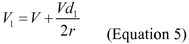
- The traveling speed of the
tire 145 can be derived from Equation 4, which is expressed in Equation 6:
- Based on this radius of rotation, the radius of rotation of the
tire 142 and thetire 145 as it rotates relative to the center of rotation C can be obtained. Since the wheelbases of theleft tires right tires left tires right tires 144, 5, 6 is the same, which is Rinner. If the wheelbases of thetire 141 andtire 142 are d2 and according to Pythagorean Theorem, the turning radius of thetire 142 can be derived, which is expressed in Equation 7:
- Similarly, the turning radius of the
tire 145 is expressed in Equation 8:
- Since the angular velocities are the same, the travelling speed of the
corresponding tire 142 can be derived fromEquations 5 and 7, as shown in Equation 9:
- Similarly, the travelling speed of the
tire 145 can be derived from Equations 6 and 8, as shown in Equation 10:
tire 142 is

chassis 1 applies a six-wheel turning method. Please refer toFig. 2 andFig. 11 together. When the turning state of rotation mode is performed, the controller (not shown inFig. 2 andFig. 11 ) will first output a 360-degree case and a turning signal to six wheels. If thetire 14 receives a 360-degree case signal, the six wheels will rotate the same angle and send out the commands including the rotation angle and the traveling speed to the controller. The controller then applies (Equation 3) to calculate the turning angle θ of the mobility device, which also includes the second operational command according to the current situation to transfer the commands to themobility device 2 so that the target angle form the operator can be achieved. Also, there are different angles that the mobility device wants to turn at different times. In addition, when thetire 14 receives the rotation state signal, thetires tires tires tires 14 and the second physical quantity of the turning angular velocity of the robot control system are sent out to the controller. After the controller estimates the turning angles, traveling speeds, and a turning center C of thetires Equation 10, the second physical quantity (not shown) will be sent back to rotate the mobility device of the robot control system to meet the needs of the operator. The different required rotation angles are also required at different times. The following describes the implementation of the 4-wheels drive mode.Fig. 12 is a top view showing the motion of thechassis 1 when thechassis 1 is on rotation mode, but the controller is also not disclosed. -
Fig. 12 is a top view showing the motion of thechassis 1 when thechassis 1 is on rotation mode and the controller is not disclosed. InFig. 12 , at least six aspects of implementing rotation mode are disclosed, including at least six types: front-rear motion, left-right motion, alternate crawling motion, in situ rotation motion, oblique direction motion and small-radius steering motion, which likes insect crawling. These six operating motions give thechassis 1 maximum flexibility when operating. The inventor classifies the above six motion states into a 360-degree case. In a 360-degree case, the first actuating signal received by the controller (not shown inFig. 12 ) includes the direction of motion and the speed of motion. The direction of motion is used to control the rolling direction of the tire 14 (used the wheel hub as a center, clockwise or counterclockwise) and the traveling direction of the tire 14 (used the wheel hub as a center, usedmobility device 2 as an axis clockwise or counterclockwise).Tire 14 axis system is applied and the speed of motion is used to control the rolling speed of the tire 14.When thetire 14 receives the first output command including the direction of motion and the speed of motion from the steering 12, the traveling direction of thetire 14 is turned ±90° with respect to the y direction and the forward and reverse rotation of thetire 14 is used to achieve the linear motion of themobility device 2 in various orientations. Details listed below are how the controller operates and drives the rotation of thetire 14. Assuming that the forward direction of the mobility device is 0°, the angle at which the mobility device wants to turn is set to θ, the current angle of thetire 14 is set to α, the forward direction of the mobility device is 0° (0 degree angle is defined as the same mobility device), the two angles are positive clockwise direction, r is the "wheel rotation direction" variable. +1 or -1 two values when the current direction is 0 to 90 degrees or between 270 and 360-degrees, r takes 1 and the wheel rotates forward and when the current direction is 90-270 degrees, r takes -1 and the wheel rotates reverse, the relationship between the traveling direction of the mobility device and the rotation direction of thetire 14 is as shown in Equation 3:
tire 14. - On rotation mode, another aspect is a rotation case, which is used in the case of a 360-degree case without moving the
mobility device 2. The rotation case is suitable for that the rotation ofmobility device 2 is required, which can change the traveling direction of thechassis 1. Please refer toFig. 13 and the controller is not disclosed, either. In a rotation state, the controller calculates and adjusts the direction of thetire 14 and the rolling speed of eachtire 14 to realize the turning of the mobility device around a center. The following details instruct how the controller calculates and drives the rotation of the wheel. It can be seen fromFIG. 13 that the currently set rotation center C is at the intersection point of the four tire diagonals of the robot control system (the interaction point of 141, 146 axle connection line and 143, 144 axle connection line), therefore, from the top view showing that the turning process of the whole robot control system can be seen as a rectangle (mobility device) rotates around the center of rotation during the turning process. Since the center of rotation of each wheel is the same during the turning process (the robot control system is regarded as a mass point), the turning angular velocity ω of eachtire 14 is the same. The following solution assumes that C-speed angular velocity of the chassis center point is not 0 and the angular velocity is greater than 0. The solution is assumed that the distances between the axle center of thetire 141 and thetire 144 is d 1 (the width of the mobility device) and the distances between the axle center of thetire 141 and thetire 143 is d 2 (the length of the mobility device). During the turning process, the linear velocity of the center point C is v and the angular velocity is w and then, the turning radius of the mass point derives from Equation 11:
- Based on this radius of rotation, the radius of rotation of the
tire tire left tires right tires right tires 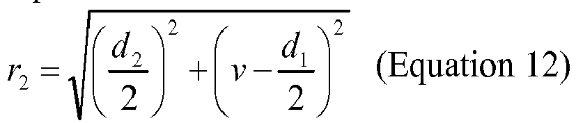
- The turning radius of
tires 142/146 can be derived from Equation 13:
- Since four tires travel around a mass point, the angular velocities w of all four tires are the same. Because the
tires tires tires 
- Similarly, the rotating speed of the
tires 
- The steering angle w 1 of the
tires 141/143 can be derived from the Equation 16:
- The steering angle of the
tire 144/146 can be derived from the Equation 17:
Equations 14, 15, 16 and 17 for the rotating speed and steering direction of the four tires to achieve control of the chassis. - Please refer to
Fig. 2 andFig. 13 together. When the turning state of rotation mode is performed, the controller (not shown inFig. 2 andFig. 13 ) will first output a 360-degree case and a turning signal to four wheels. If thetire 14 receives a 360-degree case signal, the four wheels will rotate the same angle and send out the commands including the rotation angle and the traveling speed to the controller. The controller then applies (Equation 3) to calculate the turning angle θ of the mobility device, which also includes the second operational command based on the current situation to transfer the commands to themobility device 2 so that the target angle form the operator can be achieved. - Also, there are different angles that the mobility device wants to turn at different times. In addition, when the
tire 14 receives the rotation state signal, thetires tires tires 14 and the second physical quantity of the turning angular velocity of the robot control system are sent out to the controller. After the controller estimates the turning angles, traveling speeds, and a turning center C of thetires - In summary, the present invention provides a
chassis 1. Not only is the chassis a simple structure, but also it can control the relative height of the chassis and the ground by thesuspension 11 so that thechassis 1 can be used in various terrains and environments and still maintain the chassis stable. Thetires 14 allow the chassis to move correctly and quickly to the desired location. Withdifferent mobility device 2 of the robot or a vehicle, the chassis can be used in different purpose. In addition, thechassis 1 disclosed in the present invention can travel over the obstacle mode, the climbing mode, the stairs mode and the turning mode and it can travel on different terrains and environment, so it can be widely used on the robots and the vehicles. The embodiment mentioned above is the preferred embodiment of the present invention and is not intended to limit the scope of the present invention. The descriptions mentioned above should be understood and implemented by those skilled in the relevant technology fields. Therefore, the other embodiments are deviated from the spirit, equivalent changes or modifications of the present invention shall be included in the scope of this patent application. - While the invention has been described in terms of what is presently considered to be the most practical and preferred embodiments, it is to be understood that the invention needs not be limited to the disclosed embodiments. On the contrary, it is intended to cover various modifications and similar arrangements included within the spirit and scope of the appended claims which are to be accorded with the broadest interpretation so as to encompass all such modifications and similar structures.
Claims (10)
- A chassis (1) which is connected with a mobility device (2), comprising:a suspension (11) configuring to under the bottom of the mobility device (2);a steering (12) connecting pivotally with the suspension (11);a controller (10) connecting electrically both the suspension (11) and the steering (12); anda tire (14) connecting electrically and pivotally to the steering (12), and configuring under the steering (12);wherein the steering shaft of the steering (12) axially coinciding with the steering shaft of the tire so the controller (10) govern the turning direction of the tire and the height of the suspension (11) through the suspension (11) and the steering (12).
- The chassis (1) according to claim 1, wherein the type of the suspension (11) is including an independent type, a non-independent type or a mechanical leg type.
- The chassis (1) according to claim 1, wherein the suspension is configured to adjust the height to the ground of the chassis (1).
- The chassis (1) according to claim 1, the steering further comprising a damper (121) configured to connecting the center of the tire.
- The chassis (1) according to claim 1, wherein the steering (12) configured to change the camber angle, the inclination angle, the toe angle and the caster angle of the tire (14).
- The chassis (1) according to claim 1, wherein the controller (10) connecting electrically and wirelessly to both the suspension (11) and the steering (12).
- The chassis (1) according to claim 1, wherein the tire (14) is configured to a number which is more than 2 and is an even number, and configured to drum type or spherical type.
- The chassis (1) according to claim 1, wherein motion of the chassis (1) including an obstacle mode, a climbing mode, a stairs mode and a turning mode.
- The chassis (1) according to claim 8, further comprising a 360-degree straight structure and a 360-degree rotating structures when the chassis (1) is on the turning mode.
- A robot, which is constructed by the chassis based on anyone the claim 1 to 9, including a body, a shell, a bottom portion and a chassis (1), wherein the shell and the bottom portion are connecting pivotally to each other by a pivot shaft, and the chassis are connecting pivotally to the bottom.
Applications Claiming Priority (2)
| Application Number | Priority Date | Filing Date | Title |
|---|---|---|---|
| CN201710308901.0A CN107160963B (en) | 2017-05-04 | 2017-05-04 | Wheeled motion chassis |
| PCT/CN2018/084321 WO2018201937A1 (en) | 2017-05-04 | 2018-04-25 | Wheeled movement chassis |
Publications (2)
| Publication Number | Publication Date |
|---|---|
| EP3620352A1 true EP3620352A1 (en) | 2020-03-11 |
| EP3620352A4 EP3620352A4 (en) | 2021-03-10 |
Family
ID=59813544
Family Applications (1)
| Application Number | Title | Priority Date | Filing Date |
|---|---|---|---|
| EP18795022.5A Pending EP3620352A4 (en) | 2017-05-04 | 2018-04-25 | Wheeled movement chassis |
Country Status (5)
| Country | Link |
|---|---|
| US (1) | US11260717B2 (en) |
| EP (1) | EP3620352A4 (en) |
| CN (1) | CN107160963B (en) |
| SG (1) | SG11201811623RA (en) |
| WO (1) | WO2018201937A1 (en) |
Cited By (1)
| Publication number | Priority date | Publication date | Assignee | Title |
|---|---|---|---|---|
| CN112477853A (en) * | 2020-11-11 | 2021-03-12 | 南京航空航天大学 | Vehicle longitudinal-vertical integrated control system and method equipped with non-inflatable wheels |
Families Citing this family (19)
| Publication number | Priority date | Publication date | Assignee | Title |
|---|---|---|---|---|
| GB2560328B (en) * | 2017-03-07 | 2021-12-15 | Niftylift Ltd | Base unit for a vehicle |
| CN107160963B (en) * | 2017-05-04 | 2020-08-21 | 大陆智源科技(北京)有限公司 | Wheeled motion chassis |
| US11235824B2 (en) * | 2017-12-25 | 2022-02-01 | Kubota Corporation | Work vehicle |
| CN108398948B (en) * | 2018-02-11 | 2019-06-07 | 北京三快在线科技有限公司 | Robot control method and robot controller |
| EP3587150B1 (en) * | 2018-06-08 | 2022-11-23 | Mando Corporation | Vehicle control apparatus and vehicle control method |
| DE102018126700A1 (en) * | 2018-10-25 | 2020-04-30 | Ebm-Papst St. Georgen Gmbh & Co. Kg | Modular wheel drive module |
| DE102018131850A1 (en) * | 2018-12-12 | 2020-06-18 | Schaeffler Technologies AG & Co. KG | Wheel module for a motor vehicle and corresponding motor vehicle |
| GB2582640B (en) * | 2019-03-29 | 2021-10-27 | Protean Electric Ltd | A drive arrangement for a vehicle |
| US20210276642A1 (en) * | 2019-12-18 | 2021-09-09 | Carla R. Gillett | Modular robotic vehicle comprising wheeled leg array |
| EP4116115A4 (en) * | 2020-03-02 | 2024-04-10 | Dalu Robotech Tech Beijing Co Ltd | Suspension device, suspension damping device and six-wheel bionic chassis |
| CN111619699A (en) * | 2020-05-21 | 2020-09-04 | 广东博智林机器人有限公司 | AGV moving platform and control method and control device thereof |
| CN111775721B (en) * | 2020-07-14 | 2022-05-10 | 清华大学 | Full-vector control chassis structure, and control method and device for full-vector control automobile |
| CN111942178B (en) * | 2020-08-26 | 2021-08-24 | 宁波海特技术转移有限公司 | Electric drive control system of spherical tire of automobile |
| KR20220067219A (en) | 2020-11-17 | 2022-05-24 | 현대모비스 주식회사 | Independently driving wheel module and mounting method thereof |
| CN112896309A (en) * | 2021-01-25 | 2021-06-04 | 江苏永捷工程物流有限公司 | Steering control system of multi-servo valve cooperative control heavy flat-bed transport vehicle |
| CN113818808A (en) * | 2021-10-21 | 2021-12-21 | 江西东锐机械有限公司 | Bionic type drilling machine chassis assembly |
| CN114368428B (en) * | 2022-01-11 | 2023-07-28 | 湖北汽车工业学院 | Electronic chip circuit board control device with wire control chassis |
| WO2024063703A1 (en) * | 2022-07-11 | 2024-03-28 | Delivers Ai Robotik Otonom Surus Bilgi Teknolojileri A.S. | Drivetrain system for an autonomous delivery robot |
| CN115503828B (en) * | 2022-11-16 | 2023-03-17 | 福建省威盛机械发展有限公司 | Vehicle chassis and vehicle |
Family Cites Families (44)
| Publication number | Priority date | Publication date | Assignee | Title |
|---|---|---|---|---|
| FR2281263A1 (en) * | 1974-08-08 | 1976-03-05 | Secmafer Sa | ALL TERRAIN MACHINE |
| JPS62253568A (en) * | 1986-04-28 | 1987-11-05 | Agency Of Ind Science & Technol | Transfer device |
| US4932489A (en) * | 1988-04-07 | 1990-06-12 | Transitions Research Corporation | Steering and drive means for robot vehicle |
| US4977971A (en) * | 1989-05-17 | 1990-12-18 | University Of Florida | Hybrid robotic vehicle |
| US4993912A (en) * | 1989-12-22 | 1991-02-19 | Chamberlain Mrc, Division Of Duchossois Industries, Inc. | Stair climbing robot |
| DE4005356A1 (en) * | 1990-02-16 | 1991-08-22 | Noell Gmbh | Multi-chassis vehicles - has drives to at least two wheels at each chassis to overcome obstacles |
| US5375863A (en) * | 1990-10-01 | 1994-12-27 | Leonard Studio Equipment, Inc. | Electronic steering mode shifter |
| KR20000031741A (en) * | 1998-11-10 | 2000-06-05 | 권문구 | Method for automatically controlling horizontal positioning of tractors and apparatus thereof |
| JP3749232B2 (en) * | 2002-04-01 | 2006-02-22 | 三洋電機株式会社 | Step elevation method, cart and wheelchair |
| DE60331259D1 (en) * | 2003-02-21 | 2010-03-25 | Lockheed Corp | VEHICLE WITH A LOCATED SUSPENSION AND USE METHOD THEREFOR |
| DE10334956B4 (en) * | 2003-07-31 | 2014-10-02 | Rheinmetall Landsysteme Gmbh | vehicle |
| CN2695188Y (en) * | 2003-12-04 | 2005-04-27 | 北京航空航天大学 | Leg-wheel changed structure type detecting robot |
| US20050236208A1 (en) * | 2004-04-27 | 2005-10-27 | Richard Runkles | Power wheelchair |
| US7513516B2 (en) * | 2005-08-23 | 2009-04-07 | Jri Development Group, Llc | Shock isolation cradle |
| DE102006001055A1 (en) * | 2006-01-07 | 2007-07-12 | Paczynski, Andreas, Prof. Dr.-Ing. | Drive system for e.g. drivable mobile robot, has drive wheels fastened to radial arms that are fastened to base construction in rotatable manner, where height and angle position of structure of robot depends on position of radial arms |
| US8644991B2 (en) * | 2006-10-06 | 2014-02-04 | Irobot Corporation | Maneuvering robotic vehicles |
| US8540040B2 (en) * | 2007-11-07 | 2013-09-24 | Gse Technologies, Llc | Multi-purpose ground vehicle |
| KR101004957B1 (en) | 2008-09-17 | 2010-12-28 | 현대위아 주식회사 | Robot system for 4 wheel driving and 4 wheel steering using motor |
| CN201442265U (en) * | 2009-08-21 | 2010-04-28 | 中国科学院沈阳自动化研究所 | Wheel-leg moving mechanism used for moving robot |
| US20160176452A1 (en) * | 2010-04-06 | 2016-06-23 | Robotex Inc. | Robotic system and methods of use |
| SI2414212T1 (en) * | 2010-05-28 | 2012-12-31 | John Victor Gano | Omni-directional wheel assembly and omni-directional vehicle |
| CN102649450A (en) * | 2012-04-09 | 2012-08-29 | 北京理工大学 | Design of wheel leg type moving foot of multi-joint chain link type robot |
| CN102699893B (en) * | 2012-06-07 | 2015-03-25 | 中国东方电气集团有限公司 | Differential driving magnetic attracting multifunctional wall-climbing robot with mechanical arms of multiple degrees of freedom |
| CN103661669A (en) * | 2012-09-26 | 2014-03-26 | 中国人民解放军第二炮兵工程大学 | Wheel-legged robot chassis suspension device |
| CN202896207U (en) * | 2012-09-28 | 2013-04-24 | 浙江国自机器人技术有限公司 | All-dimensional mobile chassis |
| DE102013000724B4 (en) * | 2013-01-17 | 2018-06-21 | Bruno Walter | All-terrain wheelchair |
| CZ306763B6 (en) * | 2013-09-16 | 2017-06-21 | Technická univerzita v Liberci | An undercarriage system of a wheeled vehicle designed for impassable terrains |
| US9254866B2 (en) * | 2013-11-08 | 2016-02-09 | GM Global Technology Operations LLC | Method of controlling steering of a ground vehicle |
| US10071609B2 (en) * | 2014-03-11 | 2018-09-11 | Ecole Polytechnique Federale De Lausanne (Epfl) | Vehicle having a high clearing capability |
| FR3020031B1 (en) * | 2014-04-17 | 2017-10-20 | Mecanroc | VEHICLE HAVING A CHASSIS AND A PENDULAR NACELLE |
| CN104401505B (en) * | 2014-10-27 | 2016-05-18 | 哈尔滨工业大学 | The manned lunar rover moving system of two-wheel omnidirectional damping type |
| US10165722B2 (en) * | 2014-12-05 | 2019-01-01 | Deere & Company | Scouting systems |
| WO2016119068A1 (en) * | 2015-02-01 | 2016-08-04 | Genesis Advanced Technology Inc. | Mobile platform |
| US9567021B2 (en) * | 2015-06-11 | 2017-02-14 | Christopher Mailey | Dynamically stable stair climbing home robot |
| CN105128973A (en) * | 2015-07-27 | 2015-12-09 | 徐金鹏 | Mars detection vehicle chassis |
| CN105216905B (en) * | 2015-10-27 | 2018-01-02 | 北京林业大学 | Immediately positioning and map building exploration search and rescue robot |
| EP3386778A2 (en) * | 2015-12-08 | 2018-10-17 | BAE Systems PLC | Smart material couplings |
| CN105479433B (en) | 2016-01-04 | 2017-06-23 | 江苏科技大学 | A kind of Mecanum wheel Omni-mobile transfer robot |
| CN105818633B (en) * | 2016-03-24 | 2019-01-08 | 江苏大学 | It is a kind of based on intelligent network connection multi-state suspension take aim at system and its control method in advance |
| CN105774899A (en) | 2016-03-30 | 2016-07-20 | 北京林业大学 | Mobile robot used for agriculture and forestry nursery operation |
| RU168035U1 (en) * | 2016-04-18 | 2017-01-17 | Акционерное общество Научно-Технический Центр "РОКАД" | VEHICLE VEHICLE VEHICLE WITH DIFFICULT GROUND AND RELIEF CONDITIONS |
| CN105946451B (en) * | 2016-05-06 | 2019-10-25 | 中国科学院宁波材料技术与工程研究所 | Omni-mobile platform and its steering wheel and driving wheel |
| CN106476550A (en) | 2016-12-06 | 2017-03-08 | 哈工大机器人集团上海有限公司 | A kind of wheeled robot chassis |
| CN107160963B (en) | 2017-05-04 | 2020-08-21 | 大陆智源科技(北京)有限公司 | Wheeled motion chassis |
-
2017
- 2017-05-04 CN CN201710308901.0A patent/CN107160963B/en active Active
-
2018
- 2018-04-25 WO PCT/CN2018/084321 patent/WO2018201937A1/en unknown
- 2018-04-25 SG SG11201811623RA patent/SG11201811623RA/en unknown
- 2018-04-25 US US16/606,897 patent/US11260717B2/en active Active
- 2018-04-25 EP EP18795022.5A patent/EP3620352A4/en active Pending
Cited By (1)
| Publication number | Priority date | Publication date | Assignee | Title |
|---|---|---|---|---|
| CN112477853A (en) * | 2020-11-11 | 2021-03-12 | 南京航空航天大学 | Vehicle longitudinal-vertical integrated control system and method equipped with non-inflatable wheels |
Also Published As
| Publication number | Publication date |
|---|---|
| CN107160963A (en) | 2017-09-15 |
| CN107160963B (en) | 2020-08-21 |
| WO2018201937A1 (en) | 2018-11-08 |
| SG11201811623RA (en) | 2019-01-30 |
| US20200276877A1 (en) | 2020-09-03 |
| US11260717B2 (en) | 2022-03-01 |
| EP3620352A4 (en) | 2021-03-10 |
Similar Documents
| Publication | Publication Date | Title |
|---|---|---|
| US11260717B2 (en) | Chassis | |
| US11427249B2 (en) | Control system for a tiltable vehicle | |
| US11130382B2 (en) | Vehicle and methods for improving stability and occupant comfort | |
| CN107053215B (en) | Robot control system | |
| CN107205336A (en) | A11wheel drive robotic vehicle with steering brake | |
| US20220053703A1 (en) | Baling vehicle with automated round bale ejection | |
| JP7065069B2 (en) | Mobile control device | |
| KR102415357B1 (en) | Multimode Extreme Travel Suspension Automobiles with Treadplane Sensing and Control | |
| Chung et al. | Wheeled robots | |
| CN106882283A (en) | A kind of robot system | |
| US20220324285A1 (en) | Tiltable chassis for a three-wheeled vehicle | |
| GB2516619A (en) | Land wheeled drone | |
| US11097775B2 (en) | Method and control system for establishing a steering angle of a steerable caster | |
| US11129331B2 (en) | Steering control system for harvester and methods of using the same | |
| US10543874B2 (en) | Low gravity all-surface vehicle and stabilized mount system | |
| EP3585145B1 (en) | Self-propelled robotic lawnmower comprising wheels arranged with a negative camber angle | |
| US20210354508A1 (en) | Wheel arrangement | |
| WO2023226389A1 (en) | Eccentric hemisphere wheel-type self-adaptive robot | |
| US20210394575A1 (en) | Vehicle and methods for improving stability and occupant comfort | |
| CN207240187U (en) | A kind of robot control system | |
| JP7295654B2 (en) | self-propelled robot | |
| CN111142523B (en) | Wheel-leg type mobile robot motion control system | |
| JP2006068884A (en) | Robot device and its control method, and passive wheel device | |
| JP6997568B2 (en) | Steering system | |
| CN115056880A (en) | Multi-motion dynamic robot and motion dynamic switching control method thereof |
Legal Events
| Date | Code | Title | Description |
|---|---|---|---|
| STAA | Information on the status of an ep patent application or granted ep patent |
Free format text: STATUS: THE INTERNATIONAL PUBLICATION HAS BEEN MADE |
|
| PUAI | Public reference made under article 153(3) epc to a published international application that has entered the european phase |
Free format text: ORIGINAL CODE: 0009012 |
|
| STAA | Information on the status of an ep patent application or granted ep patent |
Free format text: STATUS: REQUEST FOR EXAMINATION WAS MADE |
|
| 17P | Request for examination filed |
Effective date: 20191129 |
|
| AK | Designated contracting states |
Kind code of ref document: A1 Designated state(s): AL AT BE BG CH CY CZ DE DK EE ES FI FR GB GR HR HU IE IS IT LI LT LU LV MC MK MT NL NO PL PT RO RS SE SI SK SM TR |
|
| AX | Request for extension of the european patent |
Extension state: BA ME |
|
| DAV | Request for validation of the european patent (deleted) | ||
| DAX | Request for extension of the european patent (deleted) | ||
| A4 | Supplementary search report drawn up and despatched |
Effective date: 20210208 |
|
| RIC1 | Information provided on ipc code assigned before grant |
Ipc: B60G 17/016 20060101ALI20210202BHEP Ipc: B62D 5/04 20060101AFI20210202BHEP Ipc: B62D 7/15 20060101ALI20210202BHEP Ipc: B62D 61/10 20060101ALI20210202BHEP |
|
| STAA | Information on the status of an ep patent application or granted ep patent |
Free format text: STATUS: EXAMINATION IS IN PROGRESS |
|
| 17Q | First examination report despatched |
Effective date: 20230504 |