EP3620345A1 - Bogie framework and bogie having same - Google Patents
Bogie framework and bogie having same Download PDFInfo
- Publication number
- EP3620345A1 EP3620345A1 EP17926005.4A EP17926005A EP3620345A1 EP 3620345 A1 EP3620345 A1 EP 3620345A1 EP 17926005 A EP17926005 A EP 17926005A EP 3620345 A1 EP3620345 A1 EP 3620345A1
- Authority
- EP
- European Patent Office
- Prior art keywords
- cover plate
- sill
- cross sill
- socket
- bogie frame
- Prior art date
- Legal status (The legal status is an assumption and is not a legal conclusion. Google has not performed a legal analysis and makes no representation as to the accuracy of the status listed.)
- Withdrawn
Links
- 238000003466 welding Methods 0.000 claims description 12
- 230000003044 adaptive effect Effects 0.000 claims description 5
- 238000009434 installation Methods 0.000 abstract description 2
- 238000005516 engineering process Methods 0.000 description 5
- 239000000463 material Substances 0.000 description 4
- 238000004519 manufacturing process Methods 0.000 description 2
- 238000005192 partition Methods 0.000 description 2
- 230000002093 peripheral effect Effects 0.000 description 2
- 230000002411 adverse Effects 0.000 description 1
- 238000005266 casting Methods 0.000 description 1
- 238000013016 damping Methods 0.000 description 1
- 230000007547 defect Effects 0.000 description 1
- 230000000694 effects Effects 0.000 description 1
- 230000002452 interceptive effect Effects 0.000 description 1
- 238000000034 method Methods 0.000 description 1
- 238000012986 modification Methods 0.000 description 1
- 230000004048 modification Effects 0.000 description 1
- 230000000750 progressive effect Effects 0.000 description 1
- 239000013585 weight reducing agent Substances 0.000 description 1
Images




Classifications
-
- B—PERFORMING OPERATIONS; TRANSPORTING
- B61—RAILWAYS
- B61F—RAIL VEHICLE SUSPENSIONS, e.g. UNDERFRAMES, BOGIES OR ARRANGEMENTS OF WHEEL AXLES; RAIL VEHICLES FOR USE ON TRACKS OF DIFFERENT WIDTH; PREVENTING DERAILING OF RAIL VEHICLES; WHEEL GUARDS, OBSTRUCTION REMOVERS OR THE LIKE FOR RAIL VEHICLES
- B61F3/00—Types of bogies
- B61F3/02—Types of bogies with more than one axle
- B61F3/04—Types of bogies with more than one axle with driven axles or wheels
-
- B—PERFORMING OPERATIONS; TRANSPORTING
- B61—RAILWAYS
- B61F—RAIL VEHICLE SUSPENSIONS, e.g. UNDERFRAMES, BOGIES OR ARRANGEMENTS OF WHEEL AXLES; RAIL VEHICLES FOR USE ON TRACKS OF DIFFERENT WIDTH; PREVENTING DERAILING OF RAIL VEHICLES; WHEEL GUARDS, OBSTRUCTION REMOVERS OR THE LIKE FOR RAIL VEHICLES
- B61F5/00—Constructional details of bogies; Connections between bogies and vehicle underframes; Arrangements or devices for adjusting or allowing self-adjustment of wheel axles or bogies when rounding curves
- B61F5/50—Other details
- B61F5/52—Bogie frames
Definitions
- the present application relates to the technical field of bogies, and in particular to a bogie frame and a bogie provided with the bogie frame.
- a bogie In rail vehicles, a bogie is an important component.
- the bogie is a direct receiver of a traction force, a braking force, a load of a vehicle, and an external force, and the bogie plays a crucial role in the running quality of the vehicle and the safety of passenger transportation.
- a cross sill and side sills of a bogie frame are main load-bearing components.
- the cross sill is rigidly integrated by welding transversely between the left side sill and the right side sill.
- the cross sill may be a round tubular cross sill or a box cross sill.
- the box cross sill is formed by welding of sheets.
- two round tubular cross sills are used in parallel in the bogie frame, or one box- cross sill is used in the bogie frame.
- the structural strength of the cross sill and the structural strength of the side sills as well as the connection strength between the cross sill and the side sills is important for the overall strength of the bogie frame.
- connection has a poor welding quality, a poor the connection reliability, susceptibility of damage, a difficult manufacturability, a large space occupation, a large manufacturing workload, and a difficult installation.
- a secondary vertical damper in the conventional bogie is generally mounted between the side sill and a body bolster, moreover, the secondary vertical damper is located at an outer side of the side sill and far away from the centerline of a vehicle body.
- an up and down stroke, generated due to vibration of the vehicle body, of the secondary vertical damper is large, which may adversely affect the service life of the secondary vertical damper and may even cause damage.
- a bogie frame which not only facilitates performing the welded connection during assembly and achieves a highly reliable and highly stable welded connection, but also can provide, at an inner side region of each of side sills, a sufficient mounting space for other components, thereby improving the flexibility of design of the bogie frame.
- a bogie including the bogie frame described above is further provided according to the present application, the bogie frame of which not only facilitates performing the welded connection during assembly and achieves a highly reliable and highly stable welded connection, but also can provide, at the inner side region of each of the side sills, a sufficient mounting space for other components, thereby improving the flexibility of design of the bogie frame.
- a bogie frame is provided according to the present application, which includes two side sills and one cross sill fixedly arranged between the two side sills.
- Each of the cross sill and the two side sills is a box beam.
- the cross sill is in an H-shape.
- Each of connection portions of the cross sill at two ends thereof obliquely converges towards a transverse centerline of the cross sill.
- An inner side of each of the two side sills is provided with a socket formed by an upper cover plate and a lower cover plate of the respective side sill.
- An upper cover plate of each of the connection portions of the cross sill is butt joined to a portion, forming part of the socket, of the upper cover plate of the respective side sill.
- a lower cover plate of each of the connection portions of the cross sill is butt joined to a portion, forming part of the socket, of the lower cover plate of the respective side sill.
- An outer side vertical plate of each of the connection portions of the cross sill goes beyond an end portion of the upper cover plate and an end portion of the lower cover plate of the cross sill, and is inserted via the respective socket into the respective side sill to be connected to the respective side sill.
- the upper cover plate of the side sill extends inwards at a joint where the upper cover plate of the side sill is correspondingly connected to the cross sill, and the lower cover plate of the side sill extends inwards at a joint where the lower cover plate of the side sill is correspondingly connected to the cross sill, to form the respective socket corresponding to the respective connection portion of the cross sill.
- an end surface, at a position where the socket is formed, of the upper cover plate of the side sill is adapted to an end surface of the upper cover plate of the respective connection portion of the cross sill.
- An end surface, at a position where the socket is formed, of the lower cover plate of the side sill is adapted to an end surface of the lower cover plate of the respective connection portion of the cross sill.
- the outer side vertical plate of each of the connection portions is an inwardly concaved arc-shaped plate.
- the outer side vertical plate of each of the connection portions is formed by a first straight plate segment, a second straight plate segment and a transitional arc-shaped plate segment, the first straight plate segment is inserted into the respective socket, the second straight plate segment extends from a middle portion of the cross sill and obliquely converges towards the transverse centerline of the cross sill, and the transitional arc-shaped plate segment is arranged between the first straight plate segment and the second straight plate segment.
- the outer side vertical plate of each of the connection portions of the cross sill is inserted into the respective side sill via the respective socket, and then connected by welding to the upper cover plate, the lower cover plate and a vertical plate of the respective side sill.
- the side sill is a U-shaped structural beam with a downwardly concaved middle portion, and the socket is arranged at the downwardly concaved position of the side sill.
- a secondary vertical damper seat is provided at an outer side of the outer side vertical plate of each of the connection portions of the cross sill.
- a connection portion, for connection to a top portion of a secondary vertical damper, of a body bolster is provided at a position, right above the secondary vertical damper seat and corresponding to the secondary vertical damper seat, of the body bolster.
- the upper cover plate of each of the connection portions of the cross sill and a portion, forming part of the socket, of the upper cover plate of the respective side sill are located in a same plane and butt joined to each other.
- the lower cover plate of each of the connection portions of the cross sill and a portion, forming part of the socket, of the lower cover plate of the respective side sill are located in a same plane and butt joined to each other.
- a bogie is further provided according to the present application, which includes a bogie frame.
- the bogie frame is the bogie frame according to any one of the above aspects.
- the cross sill is directly connected to the side sills, without requiring to provide the transitional connection members in the conventional technology, thus, the bogie frame facilitates performing the welded connection during assembly, and a highly reliable and highly stable welded connection can be achieved. Since each of the connection portions of the cross sill at the two ends thereof obliquely converges towards the transverse centerline of the cross sill, a sufficient mounting space may be provided, at the inner side region of each of the side sills, for other components, thereby improving the flexibility of design of the bogie frame.
- Each of the cross sill and the side sills is provided as a box beam, which facilitates reduction of the overall weight of the frame and saves the material.
- the bogie frame of the bogie including the bogie frame according to the present application not only facilitates performing the welded connection during assembly, and achieves a highly reliable and highly stable welded connection, but also can provide, at the inner side region of each of the side sills, a sufficient mounting space for other components, thereby improving the flexibility of design of the bogie frame.
- a bogie frame is provided according to an embodiment of the present application, which not only facilitates fit-up and welding with a high reliability and a good stability, but also can provide, at an inner side region of each of side sills, a sufficient mounting space for other components, thereby improving the flexibility of design of the bogie frame.
- a bogie including the bogie frame described above is further provided according to another embodiment of the present application, which not only facilitates fit-up and welding with a high reliability and a good stability, but also can provide, at an inner side of each of side sills, a sufficient mounting space for other components, thereby improving the flexibility of design of the bogie frame.
- Figure 1 is a schematic front view showing the structure of a bogie frame of a motor unit according to the present application.
- Figure 2 is an enlarged view of part A in Figure 1 .
- Figures 3 to 6 are respectively a schematic rear view showing the structure of the bogie frame of the motor unit according to the embodiment of the present application, as well as a top view, a front view and a side view of the bogie frame of the multiple-unit train according to the embodiment of the present application.
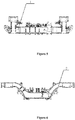
- Figure 7 is a schematic view showing the structure of a bogie of the motor unit according to an embodiment of the present application.
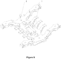
- Figure 8 is a schematic front view showing the structure of a bogie frame of a trailer according to an embodiment of the present application.
- Figure 9 is a schematic view showing the structure of a bogie of the trailer according to an embodiment of the present application.
- the bogie frame includes two side sills 2 and one cross sill 1 fixedly arranged between the two side sills 2.
- the cross sill 1 and the side sills 2 may form an H-shaped structure.
- Each of the cross sill 1 and the side sills 2 is a box beam.
- Each of a peripheral wall of the cross sill 1 and a peripheral wall of the side sill 2 is formed by an upper cover plate, a lower cover plate and vertical plates.
- the cross sill 1 is in an H-shape.
- Each of connection portions of the cross sill 1 at two ends thereof obliquely converges towards a transverse centerline of the cross sill 1, that is, in a direction of width of the train, each of the two ends of the cross sill 1 respectively forms two branches for connecting to the respective side sill 2.
- the vertical plates of each of the two branches of the respective connection portion of the cross sill 1 may include an inner side vertical plate and an outer side vertical plate, the inner side vertical plate is arranged close to the transverse centerline of the cross sill 1, and the outer side vertical plate is arranged away from the transverse centerline of the cross sill 1.
- each of the connection portions of the cross sill 1 and a middle portion of the respective side sill 2 form an opening.
- a sufficient space may be provided at the opening so as to weld the inner side vertical plate to the upper cover plate and the lower cover plate of each of the cross sill 1 and the side sill 2.
- An inner side of the side sill 2 is provided with a socket 21.
- the socket 21 is formed by the upper cover plate and the lower cover plate of the side sill 2.
- the upper cover plate of each of the connection portions of the cross sill 1 is butt joined to a portion, forming part of the socket 21, of the upper cover plate of the respective side sill 2.
- the lower cover plate of each of the connection portions of the cross sill 1 is butt joined to a portion, forming part of the socket 21, of the lower cover plate of the respective side sill 2.
- the outer side vertical plate of each of the connection portions of the cross sill 1 goes beyond an end portion of the upper cover plate and an end portion of the lower cover plate of the cross sill 1, i.e., the outer side vertical plate of the cross sill 1 extends beyond the upper cover plate and the lower cover plate of the cross sill 1 in the width direction of the train.
- An end portion of the outer side vertical plate of each of the connection portions of the cross sill 1 is inserted via the respective socket 21 into the respective side sill 2 to be connected to the respective side sill 2.
- the cross sill 1 may be fixedly connected to the side sills 2 by welding.
- the cross sill 1 and the side sills 2 of the bogie frame of the multiple-unit train may be arranged in the above way, and the cross sill 1 and the side sills 2 of the bogie frame of the trailer may also be arranged in the above way.
- the bogie frame facilitates fit-up and welding with a high reliability and a good stability. Since each of the connection portions of the cross sill 1 at the two ends thereof obliquely converges towards the transverse centerline of the cross sill 1, a sufficient mounting space may be provided, at an inner side region of each of the side sills 2, for other components, thereby improving the flexibility of design of the bogie frame.
- Each of the cross sill 1 and the side sills 2 is provided as a box beam, which facilitates reduction of the overall weight of the frame and saves the material.
- the upper cover plate and the lower cover plate of the side sill 2 extend inwards at a corresponding connection to the cross sill 1, to form the socket 21 corresponding to the respective connection portions of the cross sill 1. That is, the upper cover plate and the lower cover plate of one side sill 2 forming the socket 21 extend towards the other side sill 2, thereby facilitating the fit-up between the cross sill 1 and the side sills 2.
- the extension structure of the upper cover plate of the side sills 2 for connecting to the cross sill 1 may prevent the cross sill 1 from occupying a space, used for connection to other components, of the side sill 2, and thus may prevent other parts of the side sill 2 from interfering in the fit-up process.
- an end surface, at a position where the socket 21 is formed, of the upper cover plate of each of the side sills 2 is adaptive to an end surface of the upper cover plate of the corresponding connection portion of the cross sill 1
- an end surface, at a position where the socket 21 is formed, of the lower cover plate of each of the side sills 2 is adaptive to an end surface of the lower cover plate of the corresponding connection portion of the cross sill 1.
- "Adaptive" means that the end surfaces have corresponding shapes and may be completely and seamlessly jointed to each other.
- the end surfaces of the upper cover plate and the lower cover plate of each of the connection portions of the cross sill 1 being flat surfaces as an example
- the end faces at the portions, where the socket 21 is formed, of the upper cover plate and the lower cover plate of each of the side sills 2 are also flat surfaces with the same areas and corresponding shapes and inclination angles. This arrangement may ensure that the edge of the joints of the transverse sill 1 and the side sills 2 are smooth, the connection is reliable, and may facilitate material saving.
- the outer side vertical plate of each of the connection portions may be an inwardly concaved arc-shaped plate.
- “Inwardly concaved” refers to being concaved toward the transverse centerline of the cross sill 1, so as to further expand an available space in the bogie frame, to reduce the stress concentration at the joints of the cross sill 1 to the side sills 2, and to improve the connection strength.
- Each of the connection portions of the cross sill 1 may be designed with a variable cross section, so as to reduce the stress concentration at the joints of the cross sill 1 to the side sills 2.
- the outer side vertical plate of the connection portion may be formed by a first straight plate segment, a second straight plate segment and a transitional arc-shaped plate segment.
- the first straight plate segment is inserted into the corresponding socket 21.
- the second straight plate segment extends from a middle portion of the cross sill 1 and obliquely converges towards the transverse centerline of the cross sill 1.
- the transitional arc-shaped plate segment is arranged between the first straight plate segment and the second straight plate segment. That is, the outer side vertical plate of each of the connection portions of the cross sill 1 includes the second straight plate segment, the transitional arc-shaped plate segment and the first straight plate segment in the listed sequence from the middle portion to an outer side of the cross sill 1 in the width direction of the train. This arrangement is convenient to manufacture. In particular, providing a portion, inserted into the side sill 2 as a straight plate shape may facilitate determination of the orientation of connection.
- the outer side vertical plate of each of the connection portions of the cross sill 1 may be an integrally formed component including three segments, i.e., the second straight plate segment, the transitional arc-shaped plate segment and the first straight plate segment.
- the outer side vertical plate of each of the connection portions of the cross sill 1 may be formed by sequence welding.
- the outer side vertical plate of each of the connection portions of the cross sill 1 may be inserted into a corresponding side sill 2 via a corresponding socket 21, and then connected by welding to the upper cover plate, the lower cover plate and the vertical plate of the side sill 2, so as to ensure the reliability of connection between the cross sill 1 and the side sill 2.
- a distance by which the outer side vertical plate of each of the connection portions of the cross sill 1 is inserted into the side sill 2 may be determined in other way in practice.
- the side sill 2 may be a U-shaped structural beam with a downwardly concaved middle portion, and the downwardly concaved structure may provide a mounting space for the components and parts.
- the socket 21 may be arranged at a downwardly concaved position of the side sill 2. This arrangement may ensure the overall strength of the bogie frame, and may increase the length of each of the joints of the cross sill 1 to the side sills 2 in a length direction of the train as long as possible, thereby ensuring the area of connection of the cross sill 1 to the side sills 2.
- a secondary vertical damper seat 3 is provided at an outer side of the outer side vertical plate of each of the connection portions of the cross sill 1, and a connection portion, for connection to a top portion of a secondary vertical damper 5, of a body bolster 4 may be provided at a position, right above the secondary vertical damper seat 3 and corresponding to the secondary vertical damper seat 3, of the body bolster 4.
- This arrangement can allow the available space in the bogie frame to be sufficiently used while ensuring the damping effect, thereby reducing a stroke of the secondary vertical damper 5 generated by the rotation of the motor unit.
- the two ends of the cross sill 1 in the width direction of the motor unit each may be provided with one secondary vertical damper seat 3.
- each of the cross sill 1 and the side sill 2 may specifically be formed by castings which are fit up and welded to one another.
- a certain number of partition plates may be provided in the cross sill 1 and the side sill 2 as required, so as to further improve the torsional strength of the frame.
- the partition plate may be provided with a weight reduction hole, so as to reduce the overall weight of the bogie frame as much as possible and save the material while meeting a strength requirement of the bogie frame.
- the upper cover plate of each of the connection portions of the cross sill 1 and a portion, forming part of the socket 21, of the upper cover plate of the corresponding side sill 2 may be located in a same plane and butt jointed to each other.
- the lower cover plate of each of the connection portions of the cross sill 1 and a portion, forming part of the socket 21, of the lower cover plate of the corresponding side sill 2 may be located in a same plane and butt jointed to each other.
- Each of connection positions where the cross sill 1 is connected to the side sills 2 is located in a plane, which may provide convenience for arranging other components on the connection position.
- the upper cover plate of each of the connection portions of the cross sill 1 may alternatively have a certain height difference from the portion, forming part of the socket 21, of the upper cover plate of the corresponding side sill 2
- the lower cover plate of each of the connection portions of the cross sill 1 may alternatively have a certain height difference from the portion, forming part of the socket 21, of the lower cover plate of the corresponding side sill 2.
- the bogie frame not only facilitates fit-up and welding with a high reliability and a good stability, but also can provide, at the inner side region of each of the side sills, a sufficient mounting space for other components, thereby improving the flexibility of design of the bogie frame.
Landscapes
- Engineering & Computer Science (AREA)
- Mechanical Engineering (AREA)
- Body Structure For Vehicles (AREA)
- Handcart (AREA)
Abstract
Description
- This application claims priorities to Chinese Patent Applications No.
201710852362.7 201721202610.5 - The present application relates to the technical field of bogies, and in particular to a bogie frame and a bogie provided with the bogie frame.
- In rail vehicles, a bogie is an important component. The bogie is a direct receiver of a traction force, a braking force, a load of a vehicle, and an external force, and the bogie plays a crucial role in the running quality of the vehicle and the safety of passenger transportation.
- A cross sill and side sills of a bogie frame are main load-bearing components. The cross sill is rigidly integrated by welding transversely between the left side sill and the right side sill. The cross sill may be a round tubular cross sill or a box cross sill. The box cross sill is formed by welding of sheets. Usually, two round tubular cross sills are used in parallel in the bogie frame, or one box- cross sill is used in the bogie frame. The structural strength of the cross sill and the structural strength of the side sills as well as the connection strength between the cross sill and the side sills is important for the overall strength of the bogie frame.
- At present, two ends of the box cross sill are typically connected to the side sills respectively by transitional connection members. This connection has a poor welding quality, a poor the connection reliability, susceptibility of damage, a difficult manufacturability, a large space occupation, a large manufacturing workload, and a difficult installation.
- In addition, a secondary vertical damper in the conventional bogie is generally mounted between the side sill and a body bolster, moreover, the secondary vertical damper is located at an outer side of the side sill and far away from the centerline of a vehicle body. In operation, an up and down stroke, generated due to vibration of the vehicle body, of the secondary vertical damper is large, which may adversely affect the service life of the secondary vertical damper and may even cause damage.
- Therefore, a technical issue to be currently addressed by the person skilled in the art is to overcome the defects of the conventional bogie.
- In view of this, a bogie frame is provided according to the present application, which not only facilitates performing the welded connection during assembly and achieves a highly reliable and highly stable welded connection, but also can provide, at an inner side region of each of side sills, a sufficient mounting space for other components, thereby improving the flexibility of design of the bogie frame. A bogie including the bogie frame described above is further provided according to the present application, the bogie frame of which not only facilitates performing the welded connection during assembly and achieves a highly reliable and highly stable welded connection, but also can provide, at the inner side region of each of the side sills, a sufficient mounting space for other components, thereby improving the flexibility of design of the bogie frame.
- Technical solutions are provided according to the present application as follows.
- A bogie frame is provided according to the present application, which includes two side sills and one cross sill fixedly arranged between the two side sills. Each of the cross sill and the two side sills is a box beam. The cross sill is in an H-shape. Each of connection portions of the cross sill at two ends thereof obliquely converges towards a transverse centerline of the cross sill. An inner side of each of the two side sills is provided with a socket formed by an upper cover plate and a lower cover plate of the respective side sill. An upper cover plate of each of the connection portions of the cross sill is butt joined to a portion, forming part of the socket, of the upper cover plate of the respective side sill. A lower cover plate of each of the connection portions of the cross sill is butt joined to a portion, forming part of the socket, of the lower cover plate of the respective side sill. An outer side vertical plate of each of the connection portions of the cross sill goes beyond an end portion of the upper cover plate and an end portion of the lower cover plate of the cross sill, and is inserted via the respective socket into the respective side sill to be connected to the respective side sill.
- Preferably, the upper cover plate of the side sill extends inwards at a joint where the upper cover plate of the side sill is correspondingly connected to the cross sill, and the lower cover plate of the side sill extends inwards at a joint where the lower cover plate of the side sill is correspondingly connected to the cross sill, to form the respective socket corresponding to the respective connection portion of the cross sill.
- Preferably, an end surface, at a position where the socket is formed, of the upper cover plate of the side sill is adapted to an end surface of the upper cover plate of the respective connection portion of the cross sill. An end surface, at a position where the socket is formed, of the lower cover plate of the side sill is adapted to an end surface of the lower cover plate of the respective connection portion of the cross sill.
- Preferably, the outer side vertical plate of each of the connection portions is an inwardly concaved arc-shaped plate.
- Preferably, the outer side vertical plate of each of the connection portions is formed by a first straight plate segment, a second straight plate segment and a transitional arc-shaped plate segment, the first straight plate segment is inserted into the respective socket, the second straight plate segment extends from a middle portion of the cross sill and obliquely converges towards the transverse centerline of the cross sill, and the transitional arc-shaped plate segment is arranged between the first straight plate segment and the second straight plate segment.
- Preferably, the outer side vertical plate of each of the connection portions of the cross sill is inserted into the respective side sill via the respective socket, and then connected by welding to the upper cover plate, the lower cover plate and a vertical plate of the respective side sill.
- Preferably, the side sill is a U-shaped structural beam with a downwardly concaved middle portion, and the socket is arranged at the downwardly concaved position of the side sill.
- Preferably, a secondary vertical damper seat is provided at an outer side of the outer side vertical plate of each of the connection portions of the cross sill. A connection portion, for connection to a top portion of a secondary vertical damper, of a body bolster is provided at a position, right above the secondary vertical damper seat and corresponding to the secondary vertical damper seat, of the body bolster.
- Preferably, the upper cover plate of each of the connection portions of the cross sill and a portion, forming part of the socket, of the upper cover plate of the respective side sill are located in a same plane and butt joined to each other. The lower cover plate of each of the connection portions of the cross sill and a portion, forming part of the socket, of the lower cover plate of the respective side sill are located in a same plane and butt joined to each other.
- A bogie is further provided according to the present application, which includes a bogie frame. The bogie frame is the bogie frame according to any one of the above aspects.
- In the bogie according to the present application, the cross sill is directly connected to the side sills, without requiring to provide the transitional connection members in the conventional technology, thus, the bogie frame facilitates performing the welded connection during assembly, and a highly reliable and highly stable welded connection can be achieved. Since each of the connection portions of the cross sill at the two ends thereof obliquely converges towards the transverse centerline of the cross sill, a sufficient mounting space may be provided, at the inner side region of each of the side sills, for other components, thereby improving the flexibility of design of the bogie frame. Each of the cross sill and the side sills is provided as a box beam, which facilitates reduction of the overall weight of the frame and saves the material.
- The bogie frame of the bogie including the bogie frame according to the present application not only facilitates performing the welded connection during assembly, and achieves a highly reliable and highly stable welded connection, but also can provide, at the inner side region of each of the side sills, a sufficient mounting space for other components, thereby improving the flexibility of design of the bogie frame.
- For more clearly illustrating embodiments of the present application or the technical solutions in the conventional technology, drawings referred to describe the embodiments or the conventional technology will be briefly described hereinafter. The drawings in the following description are only examples of the present application, and for the person skilled in the art, other drawings may be obtained based on the provided drawings without any creative efforts.
-
Figure 1 is a schematic front view showing the structure of a bogie frame of a motor unit according to an embodiment of the present application; -
Figure 2 is an enlarged view of part A inFigure 1 ; -
Figure 3 is a schematic rear view showing the structure of the bogie frame of the motor unit according to the embodiment of the present application; -
Figure 4 is a top view of the bogie frame of the motor unit according to the embodiment of the present application; -
Figure 5 is a front view of the bogie frame of the motor unit according to the embodiment of the present application; -
Figure 6 is a side view of the bogie frame of the motor unit according to the embodiment of the present application; -
Figure 7 is a schematic view showing the structure of a bogie of the motor unit according to an embodiment of the present application; -
Figure 8 is a schematic front view showing the structure of a bogie frame of a trailer according to an embodiment of the present application; and -
Figure 9 is a schematic view showing the structure of a bogie of the trailer according to an embodiment of the present application. - The technical solutions in the embodiments of the present application will be described clearly and completely hereinafter in conjunction with the drawings in the embodiments of the present application. The described embodiments are only a part of the embodiments of the present application, rather than all embodiments. Based on the embodiments in the present application, all of other embodiments, made by the person skilled in the art without any creative efforts, fall into the protection scope of the present application.
- A bogie frame is provided according to an embodiment of the present application, which not only facilitates fit-up and welding with a high reliability and a good stability, but also can provide, at an inner side region of each of side sills, a sufficient mounting space for other components, thereby improving the flexibility of design of the bogie frame. A bogie including the bogie frame described above is further provided according to another embodiment of the present application, which not only facilitates fit-up and welding with a high reliability and a good stability, but also can provide, at an inner side of each of side sills, a sufficient mounting space for other components, thereby improving the flexibility of design of the bogie frame.
- Reference is made to
Figures 1 to 9 .Figure 1 is a schematic front view showing the structure of a bogie frame of a motor unit according to the present application.Figure 2 is an enlarged view of part A inFigure 1 .Figures 3 to 6 are respectively a schematic rear view showing the structure of the bogie frame of the motor unit according to the embodiment of the present application, as well as a top view, a front view and a side view of the bogie frame of the multiple-unit train according to the embodiment of the present application.Figure 7 is a schematic view showing the structure of a bogie of the motor unit according to an embodiment of the present application.Figure 8 is a schematic front view showing the structure of a bogie frame of a trailer according to an embodiment of the present application.Figure 9 is a schematic view showing the structure of a bogie of the trailer according to an embodiment of the present application. - The bogie frame according to an embodiment of the present application includes two
side sills 2 and onecross sill 1 fixedly arranged between the twoside sills 2. Thecross sill 1 and theside sills 2 may form an H-shaped structure. Each of thecross sill 1 and theside sills 2 is a box beam. Each of a peripheral wall of thecross sill 1 and a peripheral wall of theside sill 2 is formed by an upper cover plate, a lower cover plate and vertical plates. - The
cross sill 1 is in an H-shape. Each of connection portions of thecross sill 1 at two ends thereof obliquely converges towards a transverse centerline of thecross sill 1, that is, in a direction of width of the train, each of the two ends of thecross sill 1 respectively forms two branches for connecting to therespective side sill 2. Due to the H shape of thecross sill 1, the vertical plates of each of the two branches of the respective connection portion of thecross sill 1 may include an inner side vertical plate and an outer side vertical plate, the inner side vertical plate is arranged close to the transverse centerline of thecross sill 1, and the outer side vertical plate is arranged away from the transverse centerline of thecross sill 1. The arrangement of the inner side vertical plate can improve the overall strength of the bogie frame. Moreover, each of the connection portions of thecross sill 1 and a middle portion of therespective side sill 2 form an opening. A sufficient space may be provided at the opening so as to weld the inner side vertical plate to the upper cover plate and the lower cover plate of each of thecross sill 1 and theside sill 2. - An inner side of the
side sill 2 is provided with asocket 21. Thesocket 21 is formed by the upper cover plate and the lower cover plate of theside sill 2. The upper cover plate of each of the connection portions of thecross sill 1 is butt joined to a portion, forming part of thesocket 21, of the upper cover plate of therespective side sill 2. The lower cover plate of each of the connection portions of thecross sill 1 is butt joined to a portion, forming part of thesocket 21, of the lower cover plate of therespective side sill 2. - The outer side vertical plate of each of the connection portions of the
cross sill 1 goes beyond an end portion of the upper cover plate and an end portion of the lower cover plate of thecross sill 1, i.e., the outer side vertical plate of thecross sill 1 extends beyond the upper cover plate and the lower cover plate of thecross sill 1 in the width direction of the train. An end portion of the outer side vertical plate of each of the connection portions of thecross sill 1 is inserted via therespective socket 21 into the respective side sill 2 to be connected to therespective side sill 2. - The
cross sill 1 may be fixedly connected to theside sills 2 by welding. Thecross sill 1 and theside sills 2 of the bogie frame of the multiple-unit train may be arranged in the above way, and thecross sill 1 and theside sills 2 of the bogie frame of the trailer may also be arranged in the above way. - In this bogie frame, the
cross sill 1 is directly connected to theside sills 2, without requiring to provide transitional connection members in the conventional technology, thus, the bogie frame facilitates fit-up and welding with a high reliability and a good stability. Since each of the connection portions of thecross sill 1 at the two ends thereof obliquely converges towards the transverse centerline of thecross sill 1, a sufficient mounting space may be provided, at an inner side region of each of theside sills 2, for other components, thereby improving the flexibility of design of the bogie frame. Each of thecross sill 1 and theside sills 2 is provided as a box beam, which facilitates reduction of the overall weight of the frame and saves the material. - In the above embodiments, the upper cover plate and the lower cover plate of the
side sill 2 extend inwards at a corresponding connection to thecross sill 1, to form thesocket 21 corresponding to the respective connection portions of thecross sill 1. That is, the upper cover plate and the lower cover plate of oneside sill 2 forming thesocket 21 extend towards theother side sill 2, thereby facilitating the fit-up between thecross sill 1 and theside sills 2. Moreover, the extension structure of the upper cover plate of theside sills 2 for connecting to thecross sill 1 may prevent thecross sill 1 from occupying a space, used for connection to other components, of theside sill 2, and thus may prevent other parts of theside sill 2 from interfering in the fit-up process. - In the above embodiments, an end surface, at a position where the
socket 21 is formed, of the upper cover plate of each of theside sills 2 is adaptive to an end surface of the upper cover plate of the corresponding connection portion of thecross sill 1, and an end surface, at a position where thesocket 21 is formed, of the lower cover plate of each of theside sills 2 is adaptive to an end surface of the lower cover plate of the corresponding connection portion of thecross sill 1. "Adaptive" means that the end surfaces have corresponding shapes and may be completely and seamlessly jointed to each other. By taking the end surfaces of the upper cover plate and the lower cover plate of each of the connection portions of thecross sill 1 being flat surfaces as an example, the end faces at the portions, where thesocket 21 is formed, of the upper cover plate and the lower cover plate of each of theside sills 2 are also flat surfaces with the same areas and corresponding shapes and inclination angles. This arrangement may ensure that the edge of the joints of thetransverse sill 1 and theside sills 2 are smooth, the connection is reliable, and may facilitate material saving. - In the above embodiments, the outer side vertical plate of each of the connection portions may be an inwardly concaved arc-shaped plate. "Inwardly concaved" refers to being concaved toward the transverse centerline of the
cross sill 1, so as to further expand an available space in the bogie frame, to reduce the stress concentration at the joints of thecross sill 1 to theside sills 2, and to improve the connection strength. Each of the connection portions of thecross sill 1 may be designed with a variable cross section, so as to reduce the stress concentration at the joints of thecross sill 1 to theside sills 2. - Alternatively, the outer side vertical plate of the connection portion may be formed by a first straight plate segment, a second straight plate segment and a transitional arc-shaped plate segment. The first straight plate segment is inserted into the corresponding
socket 21. The second straight plate segment extends from a middle portion of thecross sill 1 and obliquely converges towards the transverse centerline of thecross sill 1. The transitional arc-shaped plate segment is arranged between the first straight plate segment and the second straight plate segment. That is, the outer side vertical plate of each of the connection portions of thecross sill 1 includes the second straight plate segment, the transitional arc-shaped plate segment and the first straight plate segment in the listed sequence from the middle portion to an outer side of thecross sill 1 in the width direction of the train. This arrangement is convenient to manufacture. In particular, providing a portion, inserted into theside sill 2 as a straight plate shape may facilitate determination of the orientation of connection. - Specifically, the outer side vertical plate of each of the connection portions of the
cross sill 1 may be an integrally formed component including three segments, i.e., the second straight plate segment, the transitional arc-shaped plate segment and the first straight plate segment. Alternatively, the outer side vertical plate of each of the connection portions of thecross sill 1 may be formed by sequence welding. - In the above embodiments, the outer side vertical plate of each of the connection portions of the
cross sill 1 may be inserted into acorresponding side sill 2 via a correspondingsocket 21, and then connected by welding to the upper cover plate, the lower cover plate and the vertical plate of theside sill 2, so as to ensure the reliability of connection between thecross sill 1 and theside sill 2. A distance by which the outer side vertical plate of each of the connection portions of thecross sill 1 is inserted into theside sill 2 may be determined in other way in practice. - In the above embodiments, the
side sill 2 may be a U-shaped structural beam with a downwardly concaved middle portion, and the downwardly concaved structure may provide a mounting space for the components and parts. Thesocket 21 may be arranged at a downwardly concaved position of theside sill 2. This arrangement may ensure the overall strength of the bogie frame, and may increase the length of each of the joints of thecross sill 1 to theside sills 2 in a length direction of the train as long as possible, thereby ensuring the area of connection of thecross sill 1 to theside sills 2. - In the above embodiments, a secondary
vertical damper seat 3 is provided at an outer side of the outer side vertical plate of each of the connection portions of thecross sill 1, and a connection portion, for connection to a top portion of a secondaryvertical damper 5, of a body bolster 4 may be provided at a position, right above the secondaryvertical damper seat 3 and corresponding to the secondaryvertical damper seat 3, of the body bolster 4. This arrangement can allow the available space in the bogie frame to be sufficiently used while ensuring the damping effect, thereby reducing a stroke of the secondaryvertical damper 5 generated by the rotation of the motor unit. Specifically, the two ends of thecross sill 1 in the width direction of the motor unit each may be provided with one secondaryvertical damper seat 3. - In the above embodiments, each of the
cross sill 1 and theside sill 2 may specifically be formed by castings which are fit up and welded to one another. A certain number of partition plates may be provided in thecross sill 1 and theside sill 2 as required, so as to further improve the torsional strength of the frame. In addition, the partition plate may be provided with a weight reduction hole, so as to reduce the overall weight of the bogie frame as much as possible and save the material while meeting a strength requirement of the bogie frame. - In the above embodiments, the upper cover plate of each of the connection portions of the
cross sill 1 and a portion, forming part of thesocket 21, of the upper cover plate of thecorresponding side sill 2 may be located in a same plane and butt jointed to each other. The lower cover plate of each of the connection portions of thecross sill 1 and a portion, forming part of thesocket 21, of the lower cover plate of thecorresponding side sill 2 may be located in a same plane and butt jointed to each other. Each of connection positions where thecross sill 1 is connected to theside sills 2 is located in a plane, which may provide convenience for arranging other components on the connection position. Of course, the upper cover plate of each of the connection portions of thecross sill 1 may alternatively have a certain height difference from the portion, forming part of thesocket 21, of the upper cover plate of thecorresponding side sill 2, and the lower cover plate of each of the connection portions of thecross sill 1 may alternatively have a certain height difference from the portion, forming part of thesocket 21, of the lower cover plate of thecorresponding side sill 2. - In addition to the bogie frame described above, a bogie including the bogie frame is further provided according to the embodiments of the present application, the bogie frame not only facilitates fit-up and welding with a high reliability and a good stability, but also can provide, at the inner side region of each of the side sills, a sufficient mounting space for other components, thereby improving the flexibility of design of the bogie frame. Reference may be made to the conventional technology for the structures of other parts of the bogie, which will not be described herein.
- The above embodiments in this specification are described in a progressive manner. Each of the embodiments is mainly focused on describing its differences from other embodiments, and references may be made among these embodiments with respect to the same or similar portions among these embodiments.
- The above explanation of the disclosed embodiments enables the person skilled in the art to implement or use the present application. It is apparent for the person skilled in the art to make multiple modifications to these embodiments. The general principles defined herein may be implemented in other embodiments without departing from the technical solution or scope of the present application. Therefore, the present application is not limited to these embodiments illustrated herein, and should conform to a broadest scope in consistent with the principles and novel features disclosed herein.
| 1 cross sill; | 2 side sill; |
| 21 socket; | 3 secondary vertical damper seat; |
| 4 body bolster; | 5 secondary vertical damper. |
Claims (10)
- A bogie frame, comprising:two side sills (2); andone cross sill (1) fixedly arranged between the two side sills (2),wherein each of the cross sill (1) and the two side sills (2) is a box beam, the cross sill (1) is in an H-shape, and each of connection portions of the cross sill (1) at two ends thereof obliquely converges towards a transverse centerline of the cross sill (1); an inner side of each of the two side sills (2) is provided with a socket (21) formed by an upper cover plate and a lower cover plate of the respective side sill (2);wherein an upper cover plate of each of the connection portions of the cross sill (1) is butt jointed to a portion, forming the socket (21), of the upper cover plate of the corresponding side sill (2), and a lower cover plate of each of the connection portions of the cross sill (1) is butt joined to a portion, forming the socket (21), of the lower cover plate of the corresponding side sill (2);wherein an outer side vertical plate of each of the connection portions of the cross sill (1) goes beyond an end portion of the upper cover plate and an end portion of the lower cover plate of the cross sill (1), and is inserted via the corresponding socket (21) into the respective side sill (2) to be connected to the respective side sill (2).
- The bogie frame according to claim 1, wherein the upper cover plate and the lower cover plate of the side sill (2) extends inwards at a corresponding connection to the cross sill (1), to form the socket (21) corresponding to the connection portions of the cross sill (1).
- The bogie frame according to claim 2, wherein an end surface, at a position where the socket (21) is formed, of the upper cover plate of each of the side sills (2) the is adaptive to an end surface of the upper cover plate of the corresponding connection portion of the cross sill (1), and an end surface, at a position where the socket (21) is formed, of the lower cover plate of each of the side sills (2) is adaptive to an end surface of the lower cover plate of the corresponding connection portion of the cross sill (1).
- The bogie frame according to claim 3, wherein the outer side vertical plate of each of the connection portions is an inwardly concaved arc-shaped plate.
- The bogie frame according to claim 3, wherein the outer side vertical plate of each of the connection portions is formed by a first straight plate segment, a second straight plate segment and a transitional arc-shaped plate segment, wherein the first straight plate segment is inserted into the socket (21), the second straight plate segment extends from a middle portion of the cross sill (1) and obliquely converges towards the transverse centerline of the cross sill (1), and the transitional arc-shaped plate segment is arranged between the first straight plate segment and the second straight plate segment.
- The bogie frame according to claim 1, wherein the outer side vertical plate of each of the connection portions of the cross sill (1) is inserted into the corresponding side sill (2) via the socket (21), and is connected by welding to the upper cover plate, the lower cover plate and a vertical plate of each of the corresponding side sill (2).
- The bogie frame according to claim 1, wherein each of the side sills (2) is a U-shaped structural beam with a downwardly concaved middle portion, and the socket (21) is arranged at a downwardly concaved position of each of the side sills (2).
- The bogie frame according to any one of claims 1 to 7, wherein a secondary vertical damper seat (3) is provided at an outer side of the outer side vertical plate of each of the connection portions of the cross sill (1), and a connection portion, for connection to a top portion of a secondary vertical damper (5), of a body bolster (4) is provided at a position, right above the secondary vertical damper seat (3) and corresponding to the secondary vertical damper seat (3), of the body bolster (4).
- The bogie frame according to any one of claims 1 to 7, wherein the upper cover plate of each of the connection portions of the cross sill (1) and a portion, forming the socket (21), of the upper cover plate of the respective side sill (2) are located in a same plane and butt jointed to each other; and the lower cover plate of each of the connection portions of the cross sill (1) and a portion, forming the socket (21), of the lower cover plate of the corresponding side sill (2) are located in a same plane and butt jointed to each other.
- A bogie, comprising a bogie frame, wherein the bogie frame is the bogie frame according to any one of claims 1 to 9.
Applications Claiming Priority (3)
| Application Number | Priority Date | Filing Date | Title |
|---|---|---|---|
| CN201710852362.7A CN107554546B (en) | 2017-09-19 | 2017-09-19 | Bogie framework and bogie with same |
| CN201721202610.5U CN207225371U (en) | 2017-09-19 | 2017-09-19 | A kind of bogie frame and the bogie with the bogie frame |
| PCT/CN2017/119258 WO2019056641A1 (en) | 2017-09-19 | 2017-12-28 | Bogie framework and bogie having same |
Publications (2)
| Publication Number | Publication Date |
|---|---|
| EP3620345A1 true EP3620345A1 (en) | 2020-03-11 |
| EP3620345A4 EP3620345A4 (en) | 2021-01-20 |
Family
ID=65810071
Family Applications (1)
| Application Number | Title | Priority Date | Filing Date |
|---|---|---|---|
| EP17926005.4A Withdrawn EP3620345A4 (en) | 2017-09-19 | 2017-12-28 | Bogie framework and bogie having same |
Country Status (3)
| Country | Link |
|---|---|
| EP (1) | EP3620345A4 (en) |
| RU (1) | RU2684830C1 (en) |
| WO (1) | WO2019056641A1 (en) |
Family Cites Families (14)
| Publication number | Priority date | Publication date | Assignee | Title |
|---|---|---|---|---|
| RU2268181C2 (en) * | 2004-01-05 | 2006-01-20 | Федеральное государственное унитарное предприятие Всероссийский научно-исследовательский и конструкторско-технологический институт подвижного состава Министерства путей сообщения Российской Федерации (ФГУП ВНИКТИ МПС России) | Frame for design row of rail vehicle bogies |
| DE102006029835A1 (en) * | 2006-06-27 | 2008-01-03 | Bombardier Transportation Gmbh | Chassis frame of a rail vehicle |
| RU2328397C2 (en) * | 2006-08-11 | 2008-07-10 | Открытое акционерное общество "МЕТРОВАГОНМАШ" | Frame of two-axial rail barrow |
| CN202413832U (en) * | 2011-12-23 | 2012-09-05 | 济南轨道交通装备有限责任公司 | High-speed rail wagon bogie framework |
| EP2783939B1 (en) * | 2011-12-23 | 2017-03-29 | CRRC Shandong Co., Ltd. | High speed railway vehicle bogie |
| CN102490754B (en) * | 2011-12-23 | 2014-10-22 | 济南轨道交通装备有限责任公司 | Bogie framework for high-speed rail wagon |
| JP5765292B2 (en) * | 2012-05-21 | 2015-08-19 | 新日鐵住金株式会社 | Bogie frame for railway vehicles |
| RU148062U1 (en) * | 2014-07-18 | 2014-11-20 | Открытое акционерное общество "Центральное конструкторское бюро транспортного машиностроения" | RAILWAY CAR VEHICLE FRAME |
| US10377393B2 (en) * | 2015-02-05 | 2019-08-13 | Crrc Qingdao Sifang Co., Ltd. | High-speed rail train bogie and frame thereof |
| AT516923A3 (en) * | 2015-03-03 | 2018-01-15 | Siemens Ag Oesterreich | Side member and cross member for a chassis frame of a rail vehicle |
| CN204674606U (en) * | 2015-04-29 | 2015-09-30 | 长春轨道客车股份有限公司 | Standard motor train unit trailer truck frame |
| CN104890693B (en) * | 2015-06-29 | 2017-06-23 | 南车株洲电力机车有限公司 | A kind of rail vehicle |
| CN205652142U (en) * | 2016-03-26 | 2016-10-19 | 中车青岛四方机车车辆股份有限公司 | Framework and have bogie of this framework |
| CN205930741U (en) * | 2016-08-11 | 2017-02-08 | 中车唐山机车车辆有限公司 | Bogie and rail vehicle |
-
2017
- 2017-12-28 WO PCT/CN2017/119258 patent/WO2019056641A1/en not_active Ceased
- 2017-12-28 EP EP17926005.4A patent/EP3620345A4/en not_active Withdrawn
-
2018
- 2018-03-27 RU RU2018110815A patent/RU2684830C1/en active
Also Published As
| Publication number | Publication date |
|---|---|
| EP3620345A4 (en) | 2021-01-20 |
| WO2019056641A1 (en) | 2019-03-28 |
| RU2684830C1 (en) | 2019-04-15 |
Similar Documents
| Publication | Publication Date | Title |
|---|---|---|
| US10494035B2 (en) | Vehicle body lower structure | |
| CN111361592B (en) | Rail vehicle and vehicle body and end underframe thereof | |
| GB2520645B (en) | Railway vehicle body structure | |
| CN111762219B (en) | Underframe side beams, body underframes, rail vehicle bodies and rail vehicles | |
| CN112026816A (en) | Undercarriage and Rail Vehicles | |
| CN109131406B (en) | Underframe assembly for rail vehicle and rail vehicle | |
| CN109178009B (en) | 100% low-floor rail vehicle underframe and 100% low-floor rail vehicle | |
| CN219406616U (en) | Front structure of vehicle body and vehicle | |
| RU2514317C2 (en) | Seat cantilever support | |
| CN105235697A (en) | Train body structure of magnetic suspension train | |
| JP6916125B2 (en) | Rail vehicle structure | |
| CN101219668B (en) | Car structure | |
| JP6462534B2 (en) | Rail vehicle structure | |
| CN111959548B (en) | Rail vehicle and chassis transition structure for connecting high-low floor thereof | |
| CN107554546B (en) | Bogie framework and bogie with same | |
| CN213168079U (en) | Front end underframe, body underframe and rail vehicle | |
| CN119058823B (en) | Front cabin structure and vehicle | |
| EP3623249B1 (en) | Trailer frame and trailer bogie having same | |
| CN219382628U (en) | Rear floor framework structure, rear floor assembly and vehicle | |
| CN217835756U (en) | Sub vehicle frame assembly and vehicle | |
| CN114148363B (en) | Rail vehicles and their end chassis | |
| JP2024121124A (en) | Railway vehicle and manufacturing method thereof | |
| CN116890940A (en) | Vehicle body components and vehicles | |
| RU2684830C1 (en) | Bogie frame and having such a frame bogie | |
| CN114954547A (en) | Vehicle body structure and rail vehicle |
Legal Events
| Date | Code | Title | Description |
|---|---|---|---|
| STAA | Information on the status of an ep patent application or granted ep patent |
Free format text: STATUS: THE INTERNATIONAL PUBLICATION HAS BEEN MADE |
|
| PUAI | Public reference made under article 153(3) epc to a published international application that has entered the european phase |
Free format text: ORIGINAL CODE: 0009012 |
|
| STAA | Information on the status of an ep patent application or granted ep patent |
Free format text: STATUS: REQUEST FOR EXAMINATION WAS MADE |
|
| 17P | Request for examination filed |
Effective date: 20191203 |
|
| AK | Designated contracting states |
Kind code of ref document: A1 Designated state(s): AL AT BE BG CH CY CZ DE DK EE ES FI FR GB GR HR HU IE IS IT LI LT LU LV MC MK MT NL NO PL PT RO RS SE SI SK SM TR |
|
| AX | Request for extension of the european patent |
Extension state: BA ME |
|
| DAV | Request for validation of the european patent (deleted) | ||
| DAX | Request for extension of the european patent (deleted) | ||
| A4 | Supplementary search report drawn up and despatched |
Effective date: 20201222 |
|
| RIC1 | Information provided on ipc code assigned before grant |
Ipc: B61F 5/52 20060101AFI20201216BHEP |
|
| GRAP | Despatch of communication of intention to grant a patent |
Free format text: ORIGINAL CODE: EPIDOSNIGR1 |
|
| STAA | Information on the status of an ep patent application or granted ep patent |
Free format text: STATUS: GRANT OF PATENT IS INTENDED |
|
| RIC1 | Information provided on ipc code assigned before grant |
Ipc: B61F 3/04 20060101ALI20221021BHEP Ipc: B61F 5/52 20060101AFI20221021BHEP |
|
| INTG | Intention to grant announced |
Effective date: 20221121 |
|
| STAA | Information on the status of an ep patent application or granted ep patent |
Free format text: STATUS: THE APPLICATION IS DEEMED TO BE WITHDRAWN |
|
| 18D | Application deemed to be withdrawn |
Effective date: 20230404 |