EP3620324A1 - Power supply device, flying tool using same and power supply method thereof - Google Patents
Power supply device, flying tool using same and power supply method thereof Download PDFInfo
- Publication number
- EP3620324A1 EP3620324A1 EP19195876.8A EP19195876A EP3620324A1 EP 3620324 A1 EP3620324 A1 EP 3620324A1 EP 19195876 A EP19195876 A EP 19195876A EP 3620324 A1 EP3620324 A1 EP 3620324A1
- Authority
- EP
- European Patent Office
- Prior art keywords
- fuel cell
- aircraft
- secondary battery
- power supply
- output
- Prior art date
- Legal status (The legal status is an assumption and is not a legal conclusion. Google has not performed a legal analysis and makes no representation as to the accuracy of the status listed.)
- Granted
Links
Images




Classifications
-
- B—PERFORMING OPERATIONS; TRANSPORTING
- B60—VEHICLES IN GENERAL
- B60L—PROPULSION OF ELECTRICALLY-PROPELLED VEHICLES; SUPPLYING ELECTRIC POWER FOR AUXILIARY EQUIPMENT OF ELECTRICALLY-PROPELLED VEHICLES; ELECTRODYNAMIC BRAKE SYSTEMS FOR VEHICLES IN GENERAL; MAGNETIC SUSPENSION OR LEVITATION FOR VEHICLES; MONITORING OPERATING VARIABLES OF ELECTRICALLY-PROPELLED VEHICLES; ELECTRIC SAFETY DEVICES FOR ELECTRICALLY-PROPELLED VEHICLES
- B60L50/00—Electric propulsion with power supplied within the vehicle
- B60L50/50—Electric propulsion with power supplied within the vehicle using propulsion power supplied by batteries or fuel cells
- B60L50/75—Electric propulsion with power supplied within the vehicle using propulsion power supplied by batteries or fuel cells using propulsion power supplied by both fuel cells and batteries
-
- H—ELECTRICITY
- H01—ELECTRIC ELEMENTS
- H01M—PROCESSES OR MEANS, e.g. BATTERIES, FOR THE DIRECT CONVERSION OF CHEMICAL ENERGY INTO ELECTRICAL ENERGY
- H01M8/00—Fuel cells; Manufacture thereof
- H01M8/04—Auxiliary arrangements, e.g. for control of pressure or for circulation of fluids
- H01M8/04298—Processes for controlling fuel cells or fuel cell systems
- H01M8/04694—Processes for controlling fuel cells or fuel cell systems characterised by variables to be controlled
- H01M8/04858—Electric variables
- H01M8/04865—Voltage
- H01M8/04888—Voltage of auxiliary devices, e.g. batteries, capacitors
-
- B—PERFORMING OPERATIONS; TRANSPORTING
- B64—AIRCRAFT; AVIATION; COSMONAUTICS
- B64D—EQUIPMENT FOR FITTING IN OR TO AIRCRAFT; FLIGHT SUITS; PARACHUTES; ARRANGEMENT OR MOUNTING OF POWER PLANTS OR PROPULSION TRANSMISSIONS IN AIRCRAFT
- B64D27/00—Arrangement or mounting of power plants in aircraft; Aircraft characterised by the type or position of power plants
- B64D27/02—Aircraft characterised by the type or position of power plants
- B64D27/24—Aircraft characterised by the type or position of power plants using steam or spring force
-
- B—PERFORMING OPERATIONS; TRANSPORTING
- B60—VEHICLES IN GENERAL
- B60L—PROPULSION OF ELECTRICALLY-PROPELLED VEHICLES; SUPPLYING ELECTRIC POWER FOR AUXILIARY EQUIPMENT OF ELECTRICALLY-PROPELLED VEHICLES; ELECTRODYNAMIC BRAKE SYSTEMS FOR VEHICLES IN GENERAL; MAGNETIC SUSPENSION OR LEVITATION FOR VEHICLES; MONITORING OPERATING VARIABLES OF ELECTRICALLY-PROPELLED VEHICLES; ELECTRIC SAFETY DEVICES FOR ELECTRICALLY-PROPELLED VEHICLES
- B60L3/00—Electric devices on electrically-propelled vehicles for safety purposes; Monitoring operating variables, e.g. speed, deceleration or energy consumption
- B60L3/0023—Detecting, eliminating, remedying or compensating for drive train abnormalities, e.g. failures within the drive train
- B60L3/0046—Detecting, eliminating, remedying or compensating for drive train abnormalities, e.g. failures within the drive train relating to electric energy storage systems, e.g. batteries or capacitors
-
- B—PERFORMING OPERATIONS; TRANSPORTING
- B60—VEHICLES IN GENERAL
- B60L—PROPULSION OF ELECTRICALLY-PROPELLED VEHICLES; SUPPLYING ELECTRIC POWER FOR AUXILIARY EQUIPMENT OF ELECTRICALLY-PROPELLED VEHICLES; ELECTRODYNAMIC BRAKE SYSTEMS FOR VEHICLES IN GENERAL; MAGNETIC SUSPENSION OR LEVITATION FOR VEHICLES; MONITORING OPERATING VARIABLES OF ELECTRICALLY-PROPELLED VEHICLES; ELECTRIC SAFETY DEVICES FOR ELECTRICALLY-PROPELLED VEHICLES
- B60L3/00—Electric devices on electrically-propelled vehicles for safety purposes; Monitoring operating variables, e.g. speed, deceleration or energy consumption
- B60L3/0023—Detecting, eliminating, remedying or compensating for drive train abnormalities, e.g. failures within the drive train
- B60L3/0053—Detecting, eliminating, remedying or compensating for drive train abnormalities, e.g. failures within the drive train relating to fuel cells
-
- B—PERFORMING OPERATIONS; TRANSPORTING
- B60—VEHICLES IN GENERAL
- B60L—PROPULSION OF ELECTRICALLY-PROPELLED VEHICLES; SUPPLYING ELECTRIC POWER FOR AUXILIARY EQUIPMENT OF ELECTRICALLY-PROPELLED VEHICLES; ELECTRODYNAMIC BRAKE SYSTEMS FOR VEHICLES IN GENERAL; MAGNETIC SUSPENSION OR LEVITATION FOR VEHICLES; MONITORING OPERATING VARIABLES OF ELECTRICALLY-PROPELLED VEHICLES; ELECTRIC SAFETY DEVICES FOR ELECTRICALLY-PROPELLED VEHICLES
- B60L58/00—Methods or circuit arrangements for monitoring or controlling batteries or fuel cells, specially adapted for electric vehicles
- B60L58/40—Methods or circuit arrangements for monitoring or controlling batteries or fuel cells, specially adapted for electric vehicles for controlling a combination of batteries and fuel cells
-
- B—PERFORMING OPERATIONS; TRANSPORTING
- B64—AIRCRAFT; AVIATION; COSMONAUTICS
- B64U—UNMANNED AERIAL VEHICLES [UAV]; EQUIPMENT THEREFOR
- B64U50/00—Propulsion; Power supply
- B64U50/10—Propulsion
- B64U50/19—Propulsion using electrically powered motors
-
- H—ELECTRICITY
- H01—ELECTRIC ELEMENTS
- H01M—PROCESSES OR MEANS, e.g. BATTERIES, FOR THE DIRECT CONVERSION OF CHEMICAL ENERGY INTO ELECTRICAL ENERGY
- H01M16/00—Structural combinations of different types of electrochemical generators
- H01M16/003—Structural combinations of different types of electrochemical generators of fuel cells with other electrochemical devices, e.g. capacitors, electrolysers
- H01M16/006—Structural combinations of different types of electrochemical generators of fuel cells with other electrochemical devices, e.g. capacitors, electrolysers of fuel cells with rechargeable batteries
-
- H—ELECTRICITY
- H01—ELECTRIC ELEMENTS
- H01M—PROCESSES OR MEANS, e.g. BATTERIES, FOR THE DIRECT CONVERSION OF CHEMICAL ENERGY INTO ELECTRICAL ENERGY
- H01M8/00—Fuel cells; Manufacture thereof
- H01M8/04—Auxiliary arrangements, e.g. for control of pressure or for circulation of fluids
- H01M8/04298—Processes for controlling fuel cells or fuel cell systems
- H01M8/043—Processes for controlling fuel cells or fuel cell systems applied during specific periods
- H01M8/04302—Processes for controlling fuel cells or fuel cell systems applied during specific periods applied during start-up
-
- H—ELECTRICITY
- H01—ELECTRIC ELEMENTS
- H01M—PROCESSES OR MEANS, e.g. BATTERIES, FOR THE DIRECT CONVERSION OF CHEMICAL ENERGY INTO ELECTRICAL ENERGY
- H01M8/00—Fuel cells; Manufacture thereof
- H01M8/04—Auxiliary arrangements, e.g. for control of pressure or for circulation of fluids
- H01M8/04298—Processes for controlling fuel cells or fuel cell systems
- H01M8/04694—Processes for controlling fuel cells or fuel cell systems characterised by variables to be controlled
- H01M8/04858—Electric variables
- H01M8/04895—Current
-
- B—PERFORMING OPERATIONS; TRANSPORTING
- B60—VEHICLES IN GENERAL
- B60L—PROPULSION OF ELECTRICALLY-PROPELLED VEHICLES; SUPPLYING ELECTRIC POWER FOR AUXILIARY EQUIPMENT OF ELECTRICALLY-PROPELLED VEHICLES; ELECTRODYNAMIC BRAKE SYSTEMS FOR VEHICLES IN GENERAL; MAGNETIC SUSPENSION OR LEVITATION FOR VEHICLES; MONITORING OPERATING VARIABLES OF ELECTRICALLY-PROPELLED VEHICLES; ELECTRIC SAFETY DEVICES FOR ELECTRICALLY-PROPELLED VEHICLES
- B60L2200/00—Type of vehicles
- B60L2200/10—Air crafts
-
- H—ELECTRICITY
- H01—ELECTRIC ELEMENTS
- H01M—PROCESSES OR MEANS, e.g. BATTERIES, FOR THE DIRECT CONVERSION OF CHEMICAL ENERGY INTO ELECTRICAL ENERGY
- H01M2250/00—Fuel cells for particular applications; Specific features of fuel cell system
- H01M2250/20—Fuel cells in motive systems, e.g. vehicle, ship, plane
-
- H—ELECTRICITY
- H02—GENERATION; CONVERSION OR DISTRIBUTION OF ELECTRIC POWER
- H02J—ELECTRIC POWER NETWORKS; CIRCUIT ARRANGEMENTS OR SYSTEMS FOR SUPPLYING OR DISTRIBUTING ELECTRIC POWER; SYSTEMS FOR STORING ELECTRIC ENERGY
- H02J2101/00—Supply or distribution of decentralised, dispersed or local electric power generation
- H02J2101/20—Dispersed power generation using renewable energy sources
- H02J2101/30—Fuel cells
-
- Y—GENERAL TAGGING OF NEW TECHNOLOGICAL DEVELOPMENTS; GENERAL TAGGING OF CROSS-SECTIONAL TECHNOLOGIES SPANNING OVER SEVERAL SECTIONS OF THE IPC; TECHNICAL SUBJECTS COVERED BY FORMER USPC CROSS-REFERENCE ART COLLECTIONS [XRACs] AND DIGESTS
- Y02—TECHNOLOGIES OR APPLICATIONS FOR MITIGATION OR ADAPTATION AGAINST CLIMATE CHANGE
- Y02E—REDUCTION OF GREENHOUSE GAS [GHG] EMISSIONS, RELATED TO ENERGY GENERATION, TRANSMISSION OR DISTRIBUTION
- Y02E60/00—Enabling technologies; Technologies with a potential or indirect contribution to GHG emissions mitigation
- Y02E60/10—Energy storage using batteries
-
- Y—GENERAL TAGGING OF NEW TECHNOLOGICAL DEVELOPMENTS; GENERAL TAGGING OF CROSS-SECTIONAL TECHNOLOGIES SPANNING OVER SEVERAL SECTIONS OF THE IPC; TECHNICAL SUBJECTS COVERED BY FORMER USPC CROSS-REFERENCE ART COLLECTIONS [XRACs] AND DIGESTS
- Y02—TECHNOLOGIES OR APPLICATIONS FOR MITIGATION OR ADAPTATION AGAINST CLIMATE CHANGE
- Y02E—REDUCTION OF GREENHOUSE GAS [GHG] EMISSIONS, RELATED TO ENERGY GENERATION, TRANSMISSION OR DISTRIBUTION
- Y02E60/00—Enabling technologies; Technologies with a potential or indirect contribution to GHG emissions mitigation
- Y02E60/30—Hydrogen technology
- Y02E60/50—Fuel cells
-
- Y—GENERAL TAGGING OF NEW TECHNOLOGICAL DEVELOPMENTS; GENERAL TAGGING OF CROSS-SECTIONAL TECHNOLOGIES SPANNING OVER SEVERAL SECTIONS OF THE IPC; TECHNICAL SUBJECTS COVERED BY FORMER USPC CROSS-REFERENCE ART COLLECTIONS [XRACs] AND DIGESTS
- Y02—TECHNOLOGIES OR APPLICATIONS FOR MITIGATION OR ADAPTATION AGAINST CLIMATE CHANGE
- Y02T—CLIMATE CHANGE MITIGATION TECHNOLOGIES RELATED TO TRANSPORTATION
- Y02T10/00—Road transport of goods or passengers
- Y02T10/60—Other road transportation technologies with climate change mitigation effect
- Y02T10/70—Energy storage systems for electromobility, e.g. batteries
Definitions
- the disclosure relates in general to a power supply device, a flying tool using the same and a power supply method thereof.
- the power requirement of an ordinary flying tool (such as multi-rotor drone) during the flight time is normally provided by a rechargeable battery.
- the rechargeable battery such as a lithium polymer battery
- the developers aim to dispose a fuel cell on the flying tool.
- the fuel cell can transform hydrogen into a large amount of energy which suffices to support the flying tool to fly for a longer time.
- Such design has the following advantages: the hydrogen fuel used in the fuel cell possesses high energy density (generated energy per unit weight, such as Wh/kg), and the generated power can meet the power requirement of a longer flight time, such that the flying tool can extend its flight distance.
- the fuel cell has a low power density (generated power per unit weight, such as W/kg), a large amount of fuel cells are needed to provide extra power to resist the instant changes in the flight environment (for example, the sudden attack of the gust).
- the increase in fuel cells has negative effects on the flying tool: the weight is increased and the flight time is reduced.
- the disclosure is directed to a power supply device, a flying tool using the same and a power supply method thereof.
- a power supply device is provided.
- the power supply device is disposed on an aircraft to provide a power to the aircraft.
- the aircraft has an average required power value.
- the power supply device includes a secondary battery, a first transformer and a fuel cell.
- the first transformer is coupled between the secondary battery and the aircraft.
- the fuel cell is coupled to the aircraft and is adapted to provide a first output current to the aircraft.
- the first transformer has an output voltage set value. When the first output end voltage of the fuel cell is lower than the output voltage set value, the first transformer provides a second output current of the secondary battery to the aircraft.
- the output voltage set value is in a voltage range with a fuel cell output power between the maximum power value of characteristic curve of the fuel cell and the average required power value of the aircraft.
- a flying tool includes an aircraft and a power supply device.
- the power supply device is disposed on the aircraft to provide a power to the aircraft.
- the aircraft has an average required power value.
- the power supply device includes a secondary battery, a first transformer and a fuel cell.
- the first transformer is coupled between the secondary battery and the aircraft.
- the fuel cell is coupled to the aircraft and is adapted to provide a first output current to the aircraft.
- the first transformer has an output voltage set value. When the first output end voltage of the fuel cell is lower than the output voltage set value, the first transformer provides a second output current of the secondary battery to the aircraft.
- the output voltage set value is in a voltage range with a fuel cell output power between the maximum power value of characteristic curve of the fuel cell and the average required power value of the aircraft.
- a power supply method of a power supply device is provided.
- the power supply device is disposed on an aircraft.
- the power supply device includes a secondary battery, a first transformer and a fuel cell.
- the secondary battery is coupled to the aircraft through the first transformer having an output voltage set value.
- the power supply method includes the following steps. A first output current is provided to the aircraft by the fuel cell.
- a second output current of the secondary battery is provided to the aircraft by the first transformer when the first output end voltage of the fuel cell is lower than the output voltage set value.
- the output voltage set value ranges between the maximum power value of characteristic curve of the fuel cell and the average required power value of the aircraft.
- FIG. 1A is a functional block diagram of a flying tool 1 according to an embodiment of the present disclosure.
- FIG. 1B is a relationship chart of flight time vs power requirement of the flying tool 1 of FIG. 1A .
- FIG. 1C is a characteristic curve chart of the fuel cell 100 of FIG. 1A .
- the flying tool 1 includes a power supply device 100 and an aircraft 10.
- the power supply device 100 is disposed on the aircraft 10 to provide a power to the aircraft 10.
- the aircraft 10 can be realized by a drone, a transportation for cargo or a transportation for passengers.
- the power supply device 100 includes a fuel cell 110, a diode 115, a secondary battery 120, a first transformer 130, a controller 140, a first switch R1 and a second switch R2.
- the first transformer 130 is coupled to the secondary battery 120 and the aircraft 10.
- the fuel cell 110 is coupled to the aircraft 10 to provide a first output current I 1 to the aircraft 10.
- the aircraft 10 has an average required power value P av .
- the average required power value P av is set according to the flight mode of the aircraft 10, and is not subjected to specific restrictions in the embodiments of the present disclosure.
- the first transformer 130 has an output voltage set value V S1 . When the first output end voltage Va at the output end 110a of the fuel cell 110 is lower than the output voltage set value V S1 , the first transformer 130 provides a second output current I 2 of the secondary battery 120 to the aircraft 10.
- the first switch R1 and the second switch R2 are electrically coupled between (such as connected in parallel with) the output end 120a of the secondary battery 120 and the output end 110a of the fuel cell 110.
- the controller 140 can control the fuel cell 110 to or not to charge the secondary battery 120 by concurrently turning on/off the first switch R1 and the second switch R2.
- the controller 140 is electrically coupled to the output end 110a of the fuel cell 110 and the output end 120a of the secondary battery 120 to detect the first output end voltage Va and the second output end voltage Vb.
- the controller 140 can determine the magnitude of the first output end voltage Va of the fuel cell 110 and that of the second output end voltage Vb of the secondary battery 120.
- the controller 140 concurrently turns on/off the first switch R1 and the second switch R2 and cause the fuel cell 110 to charge the secondary battery 120.
- the controller 140 concurrently turns off the first switch R1 and the second switch R2 and cause the fuel cell 110 not to charge the secondary battery 120.
- the diode 115 is coupled between the fuel cell 110 and the first transformer 130 and is capable of preventing the current of the secondary battery 120 from flowing to the fuel cell 110.
- the operating (working) voltage of the fuel cell 110 ranges between the output voltage set value V S1 (that is, the operating voltage lower limit) and the operating voltage upper limit V F,a (illustrated in FIG. 2A ).
- the fuel cell 110 can be formed of several fuel cell units (such as proton exchange membranes) connected in series, wherein the operating voltage of each fuel cell unit ranges between 0.608V and 0.692V.
- the fuel cell 110 is formed of 72 fuel cell units connected in series.
- the fuel cell 110 can provide an operating voltage ranging between 43.8V (such as the output voltage set value V S1 ) and 49.8V (such as the operating voltage upper limit V F,a ).
- the secondary battery 120 can be realized by a lithium battery.
- the operating voltage of the secondary battery 120 ranges between the operating voltage lower limit V L,c (illustrated in FIG. 2A ) and the operating voltage upper limit V L,a (illustrated in FIG. 2A ).
- the secondary battery 120 can be realized by several secondary battery units (such as lithium nickel manganese cobalt (NMC) batteries), wherein the operating voltage of each secondary battery unit ranges between 3.65V and 4.15V.
- the secondary battery 120 is formed of 12 secondary battery units connected in series.
- the secondary battery 120 can provide an operating voltage ranging between 43.8V (such as the operating voltage lower limit V L,c ) and 49.8V (such as the operating voltage upper limit V L,a ).
- the operating voltage upper limit V L, a of the secondary battery 120 is substantially equivalent to the operating voltage upper limit V F, a of the fuel cell 110, and the operating voltage lower limit V L,c of the secondary battery 120 is substantially equivalent to the output voltage set value V S1 of the fuel cell 110 (such as the operating voltage lower limit).
- the operating voltage upper limit V L,a of the secondary battery 120 is different from the operating voltage upper limit V F,a of the fuel cell 110, and the operating voltage lower limit V L,c of the secondary battery 120 is different from the output voltage set value V S1 of the fuel cell 110.
- the first transformer 130 can detect the node voltage Vc at the node c located on the connection line between the fuel cell 110 and the aircraft 10. Since the voltage loss between the output end 110a of the fuel cell 110 and the node c can be omitted, the node voltage Vc detected by the first transformer 130 is substantially equivalent to the first output end voltage Va at the output end 110a of the fuel cell 110. In other words, when the node voltage Vc detected by the first transformer 130 is lower than the output voltage set value V S1 (that is, when the first output end voltage Va of the fuel cell 110 is lower than the output voltage set value V S1 ), the first transformer 130 provides the second output current I 2 of the secondary battery 120 to the aircraft 10. Besides, the first transformer 130 can be realized by a step-down(Buck) converter.
- the first transformer 130 step-down the second output end voltage Vb of the secondary battery 120 to the output voltage set value V S1 .
- the first transformer 130 can be realized by a direct current to direct current (DC/DC) transformer.
- the efficiency of the first transformer 130 is lower than 100%. Therefore, the second output current I 2 will inevitable experience energy loss after flowing through the first transformer 130.
- the secondary battery 120 provides the second output current I 2 to the aircraft 10 through the first transformer 130 only when the first output end voltage Va of the fuel cell 110 is lower than the output voltage set value V S1 . Since the first output end voltage Va of the fuel cell 110 is not lower than the output voltage set value V S1 , the secondary battery 120 does not provide the current to the aircraft 10. Thus, the energy loss which occurs when the current flows through the first transformer 130 is reduced, and the power consumption of the secondary battery 120 is also reduced.
- the curve C1 denotes the relationship between the operation period (for example, when the aircraft is taking off, flying and landing) and the power of the aircraft 10, wherein P av denotes the average required power value, and P U denotes the largest required power value.
- the average required power value P av is provided by the fuel cell 110
- the instant power requirement between the average required power value P av and the largest required power value P U is provided by the secondary battery 120.
- the secondary battery 120 makes up the power deficiency of the instant power requirement of the aircraft 10 (for example, when the aircraft is making a turn or is resisting a gust).
- the power provided by the fuel cell 110 amounts to about 70% of the total power provided by the power supply device 100, and the power provided by the secondary battery 120 amounts to about 30% of the total power provided by the power supply device 100.
- the operation period T of the aircraft 10 is 500 seconds, and the total power provided by the power supply device 100 during the operation time is about 2300 watts (W).
- the power provided by the fuel cell 110 is about 1600W, and the power provided by the secondary battery 120 is about 700W.
- the energy provided by the fuel cell 110 amounts to about 93.75% of the total energy provided by the power supply device 100
- the power provided by the secondary battery 120 amounts to about 6.25% of the total power provided by the power supply device 100.
- the total power during the operation time of the aircraft 10 is about 320Wh, wherein the power provided by the fuel cell 110 is about 300Wh, and the power provided by the secondary battery 120 is about 20Wh.
- the efficiency of the first transformer 130 is 95%.
- the power provided by the secondary battery 120 drops to 19Wh (20Whx0.95) after flowing through the first transformer 130.
- the power provided by the fuel cell 110 does not flow through the first transformer 130, no energy loss will occur (the efficiency is 100%), and the power provided to the aircraft 10 by the fuel cell 110 can substantially be viewed as 300Wh.
- the secondary battery 120 provides the second output current I 2 to the aircraft 10 only when the first output end voltage Va of the fuel cell 110 is equivalent to or lower than the output voltage set value V S1 ; meanwhile, the fuel cell 110 provides the first output current I 1 to the aircraft 10. Since the first output end voltage Va of the fuel cell 110 is not lower than the output voltage set value V S1 , the secondary battery 120 does not provide the current to the aircraft 10 (the energy loss which would otherwise occurs when the current flows through the first transformer 130 will not occur), and the overall efficiency of energy transmission of the power supply device 100 is increased.
- the power supply device of the present embodiment is adapted to the situation when the base load ratio is high.
- the fuel cell 110 when the base load ratio is higher than 50%, the fuel cell 110 has the advantage of high energy density, and therefore can be used as the main power supplier to provide power supply for the base load. Since the fuel cell 110 cannot instantly increase power supply, the secondary battery 120 having high power density is used to provide extra power supply when the requirement of power supply for the load instantly increases.
- FIG. 1C is a characteristic curve chart of the fuel cell 110 which includes a voltage curve (illustrating the current vs voltage relationship) and a power curve.
- the output voltage set value V S1 is a point at the voltage curve of the characteristic curve chart.
- the output voltage set value V S1 is a voltage value corresponding to the range ⁇ P between the maximum power value P max of characteristic curve of the fuel cell 110 and the average required power value P av of the aircraft 10.
- the output power P S1 of the fuel cell 110 is greater than the average required power value P av of the aircraft 10.
- the fuel cell 110 apart from meeting the flight power requirement, will have extra power to charge the secondary battery 120 to replenish the power consumed when the power requirement of the aircraft 10 is greater than the output power P S1 of the fuel cell 110. Then, in the following flight time, the secondary battery 120 will have sufficient capacity to make up the power deficiency of the fuel cell 110 when the instant power requirement of the aircraft 10 is again greater than the output power P S1 of the fuel cell 110.
- the vertical line L1 passes through the maximum power value P max .
- the fuel cell correspondingly outputs a voltage VP and an output current I P .
- the output voltage set value V S1 moves rightward and gets closer to the vertical line L1
- the energy loss of the fuel cell 110 increases and the efficiency of the fuel cell 110 decreases.
- the fuel cell 110 outputs a voltage V Q and a current I Q , wherein the output voltage set value V S1 ranges between the voltage V P and the voltage V Q .
- the fuel cell 110 As the output voltage set value V S1 moves leftwards and gets away from the vertical line L1, the fuel cell 110 outputs a larger voltage and has a higher efficiency, but the output current decreases and the output power P S1 also decreases. Due to the above feature, the fuel cell 110 will have less capacity to charge the secondary battery 120 after providing required power to the aircraft 10. Therefore, after providing required power to the aircraft 10, the secondary battery 120 needs a longer duration to restore its capacity to the safety level. In response to the change in the flight environment and situations, the secondary battery 120 must have a sufficient allowance to meet the continuous power requirement of the aircraft 10 (for example, when the aircraft 10 is continuously climbing or accelerating). The smaller the output power P S1 of the fuel cell 110, the slower the buildup of the SOC. If the secondary battery 120 is large, the fuel cell 110 will have more time to restore the SOC of the secondary battery 120 to the expected safety level.
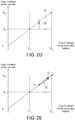
- FIGS. 2A to 2F schematic diagrams of power supply mode of the power supply device during the flight of the aircraft 10 of FIG. 1A are shown.
- the horizontal axis denotes the voltage state of the secondary battery 120
- the vertical axis denotes the voltage state of the fuel cell 110.
- the change in the first output end voltage Va of the fuel cell 110 is denoted with a bold dotted line
- the change in the second output end voltage Vb of the secondary battery 120 is denoted with a bold solid line.
- the first output end voltage Va of the fuel cell 110 is at point A and is in an initial state
- the second output end voltage Vb of the secondary battery 120 is at point A and is in an initial state.
- the first output end voltage Va of the fuel cell 110a is 0.
- the initial voltage of the secondary battery 120 is V L,a , which is the voltage of full capacity or more than 90% of full capacity of the secondary battery 120.
- the aircraft 10 starts to operate, and the secondary battery 120 provides a second output current I 2 to meet the power requirement (the load) of the aircraft 10 at the initial stage of operation of the aircraft 10 (for example, when the aircraft 10 starts to rotate its blades).
- the second output end voltage Vb of the secondary battery 120 will drop (the state of charge (SOC) will drop), for example, drop to the voltage V L,b at the state point B from the voltage V L,a at the state point A.
- the fuel cell 120 starts to operate, and the first output end voltage Va continue to increase, for example, to the voltage V S1 at the state point B from the initial voltage at the state point A (nearly 0).
- the first output end voltage Va of the fuel cell 110 (the voltage at the initial stage of operation) is lower than the node voltage Vc (the output voltage) of the first transformer 130, the diode 115 is in a reverse bias state, and the first output current I 1 still cannot flow through the diode 115 (and therefore cannot be provided to the aircraft 10).
- the power requirement of the aircraft 10 can only be provided by the secondary battery 120.
- the first transformer 130 stops providing the second output current I 2 to the aircraft 10 and causes the secondary battery 120 to stop outputting current to the aircraft 10, such that current loss which would otherwise occur when the current flows through the first transformer 130 can be avoided.
- the second output end voltage Vb of the secondary battery 120 can remain the level of the voltage V L,b at the state point B, and the first output end voltage Va of the fuel cell 110 can change according to the change in the level of the power requirement of the aircraft 10 as indicated in the upward or downward arrow illustrated in the no power supply provided by the secondary battery stage ⁇ ,2.
- the auxiliary power supply provided by the secondary battery stage ⁇ ,3 as indicated in FIG. 2C . Since the power requirement of the aircraft 10 increases (for example, when the aircraft needs a large amount of instant power to make a turn or resist a gust), the first output end voltage Va of the fuel cell 110 drops to the output voltage set value V S1 . Meanwhile, the power provided by the fuel cell 110 is insufficient for the aircraft 10, therefore the second output current I 2 generated by the secondary battery 120 is provided to the aircraft 10 through the first transformer 130 to make up the power deficiency of the fuel cell 110. During the auxiliary power supply provided by the secondary battery stage ⁇ ,3, the fuel cell 110 and the secondary battery 120 concurrently provide the required power to the aircraft 10.
- the first output current I 1 provided to the aircraft 10 by the fuel cell 110 decreases and causes the first output end voltage Va to rise as indicated in the upward arrow of FIG. 2D .
- the fuel cell 110 starts to charge the secondary battery 120 as indicated in the charging stage ⁇ ,5 of FIG. 2E .
- the curve C2 denotes that the first output end voltage Va of the fuel cell 110 is the same as the second output end voltage Vb of the secondary battery 120, and the state point C is on the curve C2.
- the step for charging the secondary battery 120 can be determined by the controller 140.
- the controller 140 (illustrated in FIG. 1A ) is configured to: (1) determine whether the first output end voltage Va of the fuel cell 110 is equivalent to or higher than the second output end voltage Vb of the secondary battery 120; (2) if yes, control the first switch R1 and the second switch R2 to be concurrently conductive and cause the fuel cell 110 to charge the secondary battery 120.
- the first output end voltage Va of the fuel cell 110 and the second output end voltage Vb of the secondary battery 120 continues to rise until the SOC of the secondary battery 120 is full, such as reaches the state point E. Meanwhile, the fuel cell 110 stops charging the secondary battery 120;.
- the fuel cell 110 needs to increase the current provided to the aircraft 10 and cause the first output end voltage Va of the fuel cell 110 to drop as indicated in the downward arrow of the no power supply provided by the secondary battery stage ⁇ ,6 of FIG. 2F .
- the fuel cell 110 stops charging the secondary battery 120 to provide more current to the aircraft 10.
- the step of stopping charging the secondary battery 120 can be completed by the controller 140.
- the controller 140 (illustrated in FIG. 1A ) is configured to: (1) determine whether the current direction of the second switch R2 moves towards Va from Vb (the discharging direction of the secondary battery); (2) if yes, control the first switch R1 and the second switch R2 to be concurrently non-conductive to stop charging the secondary battery 120.
- the secondary battery 120 when the first output end voltage Va of the fuel cell 110 is substantially equivalent to or higher than the output voltage set value V S1 , the secondary battery 120 does not provide the current to the aircraft 10 to avoid the power of the secondary battery 120 being consumed and reduce the energy loss which would other occur when the current flows through the first transformer 130.
- the secondary battery 120 provides power to the aircraft 10 only when the output power of the fuel cell 110 cannot match the power requirement of the aircraft 10.
- the secondary battery 120 provides the second output current I 2 to the aircraft 10 to replenish the power of the aircraft 10.
- the first output end voltage Va of the fuel cell 110 also varies with the power requirement of the aircraft 10.
- the fuel cell 110 charges the secondary battery 120 until the SOC of the secondary battery 120 reaches a pre-set capacity (for example, more than 90% of the full capacity of the secondary battery 120, but the preset embodiment is not limited thereto). Or, the fuel cell 110 stops charging the secondary battery 120 when the power requirement of the aircraft 10 instantly increases and causes the first output end voltage Va of the fuel cell 110 to drop.
- a pre-set capacity for example, more than 90% of the full capacity of the secondary battery 120, but the preset embodiment is not limited thereto.
- FIG. 3A is a schematic diagram of a flying tool 2 according to another embodiment of the present disclosure.
- FIG. 3B is a characteristic curve chart of the fuel cell 110 of FIG. 3A .
- the flying tool 2 includes a power supply device 200 and the aircraft 10.
- the power supply device 200 is disposed on the aircraft 10 to provide a power to the aircraft 10.
- the power supply device 200 includes a fuel cell 110, a diode 115, a secondary battery 120, a first transformer 130 and a second transformer 230.
- the first transformer 130 is coupled between the aircraft 10 and the output end 120a of the secondary battery 120.
- the second transformer 230 is coupled between the output end 110a of the fuel cell 110 and the output end 120a of the secondary battery 120.
- the aircraft 10 is coupled to the output end 110a of the fuel cell 110 and the output end 130a of the first transformer 130 to receive power supply from the fuel cell 110 and the first transformer 130.
- the second transformer 230 has an input voltage set value V S2 .
- the first output end voltage Va of the fuel cell 110 is lower than the output voltage set value V S1 of the first transformer 130, the second output current I 2 of the secondary battery 120 provides power to the aircraft 10 through the first transformer 130.
- the first output end voltage Va of the fuel cell 110 is equivalent to or higher than the input voltage set value V S2 of the second transformer 230, the fuel cell 110 charges the secondary battery 120.
- the input voltage set value V S2 is higher than the output voltage set value V S1 .
- the operating voltage of the secondary battery 120 is higher than the operating voltage of the fuel cell 110. Therefore, the second transformer 230 can be realized by a booster, which boosts the first output end voltage Va of the fuel cell 110 to charge the secondary battery 120.
- the first transformer 130 can be realized by astep-down(Buck) converter, which steps-down the second output end voltage Vb of the secondary battery 120 to match the output voltage set value V S1 of the first transformer 130.
- the second transformer 230 can be realized by a direct current to direct current (DC/DC) transformer.
- the output voltage set value V S1 of the fuel cell 110 (that is, the operating voltage lower limit) is substantially equivalent to or lower than the operating voltage lower limit of the secondary battery 120, and the operating voltage of the secondary battery 120 upper limit is higher than the operating voltage upper limit of the fuel cell 110.
- the fuel cell 110 can be formed by several fuel cell units connected in series, wherein the operating voltage of each fuel cell unit ranges between 0.625V and 0.65V. Let the fuel cell 110 be formed of 72 fuel cell units connected in series. The fuel cell 110 can provide an operating voltage ranging between 45V (the output voltage set value V S1 ) and 46.8V (the operating voltage upper limit).
- the secondary battery 120 can be formed by several secondary battery units connected in series, wherein the operating voltage of each secondary battery unit ranges between 3.2V and 4.15V. Let the secondary battery 120 be formed of 14 secondary battery units connected in series. The secondary battery 120 can provide an operating voltage ranging between 44.8V (the operating voltage lower limit) and 58.1V (such as the operating voltage upper limit).
- the determination of the output voltage set value V S1 of the first transformer 130 is similar to that of the output voltage set value V S1 disclosed in above embodiment, and the similarities are not repeated here.
- the determination of the input voltage set value V S2 of the second transformer 230 is disclosed below.
- the input voltage set value V S2 is a point at the voltage curve of the characteristic curve chart.
- the input voltage set value V S2 is a voltage value corresponding to the range ⁇ P between the maximum power value P max of the fuel cell 110 of characteristic curve and the average required power value P av of the aircraft 10, and the input voltage set value V S2 is greater than the output voltage set value V S1 .
- the first output end voltage Va of the fuel cell 110 ranges between the output voltage set value V S1 and the input voltage set value V S2 , the power requirement of the aircraft 10 is provided by the fuel cell 110 only, and no power is provided to the aircraft 10 from the secondary battery 120.
- FIG. 4A is a schematic diagram of a flying tool 3 according to another embodiment of the present disclosure.
- FIG. 4B is a schematic diagram of the setting mode of the output voltage set value V S1 of the first transformer 130 and the input voltage set value V S2 of the second transformer 230 of FIG. 4A .
- the flying tool 3 includes a power supply device 300 and an aircraft 10.
- the power supply device 300 is disposed on the aircraft 10 to provide a power to the aircraft 10.
- the power supply device 300 includes a fuel cell 110, a diode 115, a secondary battery 120, a first transformer 130, a second transformer 230 and a controller 340.
- the first transformer 130 is coupled between the aircraft 10 and the output end 120a of the secondary battery 120.
- the second transformer 230 is coupled between the output end 110a of the fuel cell 110 and the output end 120a of the secondary battery 120.
- the aircraft 10 is coupled to the output end 110a of the fuel cell 110 and the output end 130a of the first transformer 130 to receive power supply from the fuel cell 110 and the first transformer 130.
- the controller 340 is electrically coupled to the secondary battery 120, the first transformer 130 and the second transformer 230. In the preset embodiment, the controller 340 changes the output voltage set value V S1 and the input voltage set value V S2 according to the SOC of the secondary battery 120.
- the second pre-set capacity P2 is higher than the first pre-set capacity P1.
- the controller 340 decreases the output voltage set value V S1 to reduce the chance at which the secondary battery 120 provides power to the aircraft 10. That is, the probability or time period of the secondary battery 120 providing power to the aircraft 10 is reduced, and the lifespan of the secondary battery 120 is prolonged.
- the controller 340 can decrease the output voltage set value V S1 to increase the chance at which the fuel cell 110 provides power to the aircraft 10.
- the controller 340 can increase the input voltage set value V S2 and reduce the chance at which the fuel cell 110 charges the secondary battery 120, that is, the probability or time period of the fuel cell 110 charging the secondary battery 120 is reduced, and the probability or time period of the fuel cell 110 operating with higher efficiency (high output voltage) at a range is increased.
- the input voltage set value V S2 when the SOC of the secondary battery 120 is equivalent to the second pre-set capacity P2, the input voltage set value V S2 can be 46.8V; when the SOC of the secondary battery 120 is 100%, the input voltage set value V S2 can be 47.8V; the change between 46.8V and 47.8V can be linear. Furthermore, the SOC of the secondary battery 120 ranges between 0% and the second pre-set capacity P2, and the input voltage set value V S2 can remain as a constant.
- the output voltage set value V S1 when the SOC of the secondary battery 120 is equivalent to the first pre-set capacity P1, the output voltage set value V S1 can be 45V; when the SOC of the secondary battery 120 is 0%, the output voltage set value V S1 can be 44V; the change between 45V and 44V can be linear. Moreover, the SOC of the secondary battery 120 ranges between the first preset capacity P1 and 100%, the output voltage set value V S1 can remain as a constant.
- FIG. 4C another schematic diagram of the setting mode of the output voltage set value V S1 of the first transformer 130 and the input voltage set value V S2 of the second transformer 230 of FIG. 4A is shown.
- the SOC of the secondary battery 120 ranges between the second pre-set capacity P2 and 100%, and the output voltage set value V S1 rises as the SOC increases.
- the SOC of the secondary battery 120 is substantially equivalent to or higher than the second pre-set capacity P2, the SOC of the secondary battery 120 is sufficient, and the first transformer 130 can increase the chance at which the secondary battery 120 provides power to the aircraft 10. That is, the probability or time period of the secondary battery 120 providing power to the aircraft 10 is increased.
- the higher the SOC of the secondary battery 120 the larger the output voltage set value V S1 , and the chance of the secondary battery 120 providing power to the aircraft 10 increases as the SOC of the secondary battery 120 increases.
- the controller 340 can decrease the input voltage set value V S2 and increase the chance at which the fuel cell 110 charges the secondary battery 120. That is, the probability or time of the fuel cell 110 charging the secondary battery 120 is increased. Moreover, since the lower the SOC of the secondary battery 120, the smaller the input voltage set value V S2 , and the chance of the fuel cell 110 charging the secondary battery 120 increases as the SOC of the secondary battery 120 decreases.
- the first pre-set capacity P1 can be 30%, and the second pre-set capacity P2 can be 70%, but the present disclosure is not limited thereto. Due to the features of the secondary battery 120, the lifespan of the secondary battery 120 will be reduced when the SOC of the secondary battery 120 is too high or too low. Since the SOC of the secondary battery 120 can be controlled to a suitable range (such as between the first pre-set capacity P1 and the second pre-set capacity P2) according to the above arrangement of the present disclosure, the lifespan of the secondary battery 120 can be prolonged.
Landscapes
- Engineering & Computer Science (AREA)
- Sustainable Energy (AREA)
- Life Sciences & Earth Sciences (AREA)
- Sustainable Development (AREA)
- Power Engineering (AREA)
- Chemical & Material Sciences (AREA)
- Transportation (AREA)
- Mechanical Engineering (AREA)
- Electrochemistry (AREA)
- General Chemical & Material Sciences (AREA)
- Chemical Kinetics & Catalysis (AREA)
- Manufacturing & Machinery (AREA)
- Combustion & Propulsion (AREA)
- Aviation & Aerospace Engineering (AREA)
- Fuel Cell (AREA)
- Secondary Cells (AREA)
- Charge And Discharge Circuits For Batteries Or The Like (AREA)
Abstract
Description
- The disclosure relates in general to a power supply device, a flying tool using the same and a power supply method thereof.
- The power requirement of an ordinary flying tool (such as multi-rotor drone) during the flight time is normally provided by a rechargeable battery. However, the rechargeable battery (such as a lithium polymer battery), under the constraint of limited space and weight, can only support the flying tool to fly for less than an hour. In recent years, the developers aim to dispose a fuel cell on the flying tool. The fuel cell can transform hydrogen into a large amount of energy which suffices to support the flying tool to fly for a longer time. Such design has the following advantages: the hydrogen fuel used in the fuel cell possesses high energy density (generated energy per unit weight, such as Wh/kg), and the generated power can meet the power requirement of a longer flight time, such that the flying tool can extend its flight distance.
- However, since the fuel cell has a low power density (generated power per unit weight, such as W/kg), a large amount of fuel cells are needed to provide extra power to resist the instant changes in the flight environment (for example, the sudden attack of the gust). The increase in fuel cells has negative effects on the flying tool: the weight is increased and the flight time is reduced.
- Therefore, how to provide an efficient power supply method to increase the flight time or length of the flying tool has become a prominent task for the industries.
- The disclosure is directed to a power supply device, a flying tool using the same and a power supply method thereof.
- According to an embodiment of the present disclosure, a power supply device is provided. The power supply device is disposed on an aircraft to provide a power to the aircraft. The aircraft has an average required power value. The power supply device includes a secondary battery, a first transformer and a fuel cell. The first transformer is coupled between the secondary battery and the aircraft. The fuel cell is coupled to the aircraft and is adapted to provide a first output current to the aircraft. The first transformer has an output voltage set value. When the first output end voltage of the fuel cell is lower than the output voltage set value, the first transformer provides a second output current of the secondary battery to the aircraft. The output voltage set value is in a voltage range with a fuel cell output power between the maximum power value of characteristic curve of the fuel cell and the average required power value of the aircraft.
- According to another embodiment of the present disclosure, a flying tool is provided. The flying tool includes an aircraft and a power supply device. The power supply device is disposed on the aircraft to provide a power to the aircraft. The aircraft has an average required power value. The power supply device includes a secondary battery, a first transformer and a fuel cell. The first transformer is coupled between the secondary battery and the aircraft. The fuel cell is coupled to the aircraft and is adapted to provide a first output current to the aircraft. The first transformer has an output voltage set value. When the first output end voltage of the fuel cell is lower than the output voltage set value, the first transformer provides a second output current of the secondary battery to the aircraft. The output voltage set value is in a voltage range with a fuel cell output power between the maximum power value of characteristic curve of the fuel cell and the average required power value of the aircraft.
- According to an alternate embodiment of the present disclosure, a power supply method of a power supply device is provided. The power supply device is disposed on an aircraft. The power supply device includes a secondary battery, a first transformer and a fuel cell. The secondary battery is coupled to the aircraft through the first transformer having an output voltage set value. The power supply method includes the following steps. A first output current is provided to the aircraft by the fuel cell. A second output current of the secondary battery is provided to the aircraft by the first transformer when the first output end voltage of the fuel cell is lower than the output voltage set value. The output voltage set value ranges between the maximum power value of characteristic curve of the fuel cell and the average required power value of the aircraft.
- The above and other aspects of the disclosure will become better understood with regards to the following detailed description of the preferred but non-limiting embodiment (s). The following description is made with reference to the accompanying drawings.
-
-
FIG. 1A is a functional block diagram of a flying tool according to an embodiment of the present disclosure. -
FIG. 1B is a relationship chart of flight time vs power requirement of the flying tool ofFIG. 1A . -
FIG. 1C is a characteristic curve chart of the fuel cell ofFIG. 1A . -
FIGS. 2A to 2F are schematic diagrams of power supply mode of the power supply device during the flight of the aircraft ofFIG. 1A . -
FIG. 3A is a schematic diagram of a flying tool according to another embodiment of the present disclosure. -
FIG. 3B is a characteristic curve chart of the fuel cell ofFIG. 3 . -
FIG. 4A is a schematic diagram of a flying tool according to another embodiment of the present disclosure. -
FIG. 4B is a schematic diagram of the setting mode of the output voltage set value of the first transformer and the input voltage set value of the second transformer ofFIG. 4A . -
FIG. 4C is another schematic diagram of the setting mode of the output voltage set value of the first transformer and the input voltage set value of the second transformer ofFIG. 4A . - For the objects, structures, technical features and functions of the present disclosure to be more easily understood by anyone ordinary skilled in the technology field, a number of exemplary embodiments are disclosed below with detailed descriptions and accompanying drawings.
- Refer to
FIG. 1A to 1C .FIG. 1A is a functional block diagram of a flyingtool 1 according to an embodiment of the present disclosure.FIG. 1B is a relationship chart of flight time vs power requirement of the flyingtool 1 ofFIG. 1A .FIG. 1C is a characteristic curve chart of thefuel cell 100 ofFIG. 1A . The flyingtool 1 includes apower supply device 100 and anaircraft 10. Thepower supply device 100 is disposed on theaircraft 10 to provide a power to theaircraft 10. Theaircraft 10 can be realized by a drone, a transportation for cargo or a transportation for passengers. - As indicated in
FIG. 1A , thepower supply device 100 includes afuel cell 110, adiode 115, asecondary battery 120, afirst transformer 130, acontroller 140, a first switch R1 and a second switch R2. Thefirst transformer 130 is coupled to thesecondary battery 120 and theaircraft 10. Thefuel cell 110 is coupled to theaircraft 10 to provide a first output current I1 to theaircraft 10. Theaircraft 10 has an average required power value Pav. The average required power value Pav is set according to the flight mode of theaircraft 10, and is not subjected to specific restrictions in the embodiments of the present disclosure. Thefirst transformer 130 has an output voltage set value VS1. When the first output end voltage Va at theoutput end 110a of thefuel cell 110 is lower than the output voltage set value VS1, thefirst transformer 130 provides a second output current I2 of thesecondary battery 120 to theaircraft 10. - As indicated in
FIG. 1A , the first switch R1 and the second switch R2 are electrically coupled between (such as connected in parallel with) theoutput end 120a of thesecondary battery 120 and theoutput end 110a of thefuel cell 110. Thecontroller 140 can control thefuel cell 110 to or not to charge thesecondary battery 120 by concurrently turning on/off the first switch R1 and the second switch R2. Thecontroller 140 is electrically coupled to theoutput end 110a of thefuel cell 110 and theoutput end 120a of thesecondary battery 120 to detect the first output end voltage Va and the second output end voltage Vb. Thecontroller 140 can determine the magnitude of the first output end voltage Va of thefuel cell 110 and that of the second output end voltage Vb of thesecondary battery 120. When the first output end voltage Va of thefuel cell 110 is equivalent to or higher than the second output end voltage Vb at theoutput end 120a of thesecondary battery 120, thecontroller 140 concurrently turns on/off the first switch R1 and the second switch R2 and cause thefuel cell 110 to charge thesecondary battery 120. When the first output end voltage Va of thefuel cell 110 is lower than the second output end voltage Vb of the secondary battery 12, thecontroller 140 concurrently turns off the first switch R1 and the second switch R2 and cause thefuel cell 110 not to charge thesecondary battery 120. - Besides, the
diode 115 is coupled between thefuel cell 110 and thefirst transformer 130 and is capable of preventing the current of thesecondary battery 120 from flowing to thefuel cell 110. - The operating (working) voltage of the
fuel cell 110 ranges between the output voltage set value VS1 (that is, the operating voltage lower limit) and the operating voltage upper limit VF,a (illustrated inFIG. 2A ). In an embodiment, thefuel cell 110 can be formed of several fuel cell units (such as proton exchange membranes) connected in series, wherein the operating voltage of each fuel cell unit ranges between 0.608V and 0.692V. Thefuel cell 110 is formed of 72 fuel cell units connected in series. Thefuel cell 110 can provide an operating voltage ranging between 43.8V (such as the output voltage set value VS1) and 49.8V (such as the operating voltage upper limit VF,a). - The
secondary battery 120 can be realized by a lithium battery. The operating voltage of thesecondary battery 120 ranges between the operating voltage lower limit VL,c (illustrated inFIG. 2A ) and the operating voltage upper limit VL,a (illustrated inFIG. 2A ). In an embodiment, thesecondary battery 120 can be realized by several secondary battery units (such as lithium nickel manganese cobalt (NMC) batteries), wherein the operating voltage of each secondary battery unit ranges between 3.65V and 4.15V. Thesecondary battery 120 is formed of 12 secondary battery units connected in series. Thesecondary battery 120 can provide an operating voltage ranging between 43.8V (such as the operating voltage lower limit VL,c) and 49.8V (such as the operating voltage upper limit VL,a). - In an embodiment, the operating voltage upper limit VL,a of the
secondary battery 120 is substantially equivalent to the operating voltage upper limit VF,a of thefuel cell 110, and the operating voltage lower limit VL,c of thesecondary battery 120 is substantially equivalent to the output voltage set value VS1 of the fuel cell 110 (such as the operating voltage lower limit). In another embodiment, the operating voltage upper limit VL,a of thesecondary battery 120 is different from the operating voltage upper limit VF,a of thefuel cell 110, and the operating voltage lower limit VL,c of thesecondary battery 120 is different from the output voltage set value VS1 of thefuel cell 110. - The
first transformer 130 can detect the node voltage Vc at the node c located on the connection line between thefuel cell 110 and theaircraft 10. Since the voltage loss between theoutput end 110a of thefuel cell 110 and the node c can be omitted, the node voltage Vc detected by thefirst transformer 130 is substantially equivalent to the first output end voltage Va at theoutput end 110a of thefuel cell 110. In other words, when the node voltage Vc detected by thefirst transformer 130 is lower than the output voltage set value VS1 (that is, when the first output end voltage Va of thefuel cell 110 is lower than the output voltage set value VS1), thefirst transformer 130 provides the second output current I2 of thesecondary battery 120 to theaircraft 10. Besides, thefirst transformer 130 can be realized by a step-down(Buck) converter. Thus, when the second output end voltage Vb of thesecondary battery 120 is higher than the output voltage set value VS1, thefirst transformer 130 step-down the second output end voltage Vb of thesecondary battery 120 to the output voltage set value VS1. In an embodiment, thefirst transformer 130 can be realized by a direct current to direct current (DC/DC) transformer. - Generally speaking, the efficiency of the
first transformer 130 is lower than 100%. Therefore, the second output current I2 will inevitable experience energy loss after flowing through thefirst transformer 130. Thesecondary battery 120 provides the second output current I2 to theaircraft 10 through thefirst transformer 130 only when the first output end voltage Va of thefuel cell 110 is lower than the output voltage set value VS1. Since the first output end voltage Va of thefuel cell 110 is not lower than the output voltage set value VS1, thesecondary battery 120 does not provide the current to theaircraft 10. Thus, the energy loss which occurs when the current flows through thefirst transformer 130 is reduced, and the power consumption of thesecondary battery 120 is also reduced. - As indicated in
FIG. 1B , the curve C1 denotes the relationship between the operation period (for example, when the aircraft is taking off, flying and landing) and the power of theaircraft 10, wherein Pav denotes the average required power value, and PU denotes the largest required power value. Within the operation period T of theaircraft 10, the average required power value Pav is provided by thefuel cell 110, and the instant power requirement between the average required power value Pav and the largest required power value PU is provided by thesecondary battery 120. In other words, thesecondary battery 120 makes up the power deficiency of the instant power requirement of the aircraft 10 (for example, when the aircraft is making a turn or is resisting a gust). In terms of the power (work/unit time) indicated in the curve C1, the power provided by thefuel cell 110 amounts to about 70% of the total power provided by thepower supply device 100, and the power provided by thesecondary battery 120 amounts to about 30% of the total power provided by thepower supply device 100. In an embodiment, the operation period T of theaircraft 10 is 500 seconds, and the total power provided by thepower supply device 100 during the operation time is about 2300 watts (W). The power provided by thefuel cell 110 is about 1600W, and the power provided by thesecondary battery 120 is about 700W. - In the preset embodiment, in terms of energy (that is, the integral area under the curve C1), the energy provided by the
fuel cell 110 amounts to about 93.75% of the total energy provided by thepower supply device 100, and the power provided by thesecondary battery 120 amounts to about 6.25% of the total power provided by thepower supply device 100. In an embodiment, the total power during the operation time of theaircraft 10 is about 320Wh, wherein the power provided by thefuel cell 110 is about 300Wh, and the power provided by thesecondary battery 120 is about 20Wh. Suppose the efficiency of thefirst transformer 130 is 95%. The power provided by thesecondary battery 120 drops to 19Wh (20Whx0.95) after flowing through thefirst transformer 130. Since the power provided by thefuel cell 110 does not flow through thefirst transformer 130, no energy loss will occur (the efficiency is 100%), and the power provided to theaircraft 10 by thefuel cell 110 can substantially be viewed as 300Wh. Thus, in terms of thepower supply device 100, the overall efficiency of energy transmission can reach as high as 99.7% (formula: (300x100%+20x95%)/320=99.7%). - As disclosed above, the
secondary battery 120 provides the second output current I2 to theaircraft 10 only when the first output end voltage Va of thefuel cell 110 is equivalent to or lower than the output voltage set value VS1; meanwhile, thefuel cell 110 provides the first output current I1 to theaircraft 10. Since the first output end voltage Va of thefuel cell 110 is not lower than the output voltage set value VS1, thesecondary battery 120 does not provide the current to the aircraft 10 (the energy loss which would otherwise occurs when the current flows through thefirst transformer 130 will not occur), and the overall efficiency of energy transmission of thepower supply device 100 is increased. - The power supply device of the present embodiment is adapted to the situation when the base load ratio is high. For example, when the base load ratio is higher than 50%, the
fuel cell 110 has the advantage of high energy density, and therefore can be used as the main power supplier to provide power supply for the base load. Since thefuel cell 110 cannot instantly increase power supply, thesecondary battery 120 having high power density is used to provide extra power supply when the requirement of power supply for the load instantly increases. - The determination of the output voltage set value VS1 is disclosed below.
-
FIG. 1C is a characteristic curve chart of thefuel cell 110 which includes a voltage curve (illustrating the current vs voltage relationship) and a power curve. As indicated inFIG. 1C , the output voltage set value VS1 is a point at the voltage curve of the characteristic curve chart. The output voltage set value VS1 is a voltage value corresponding to the range ΔP between the maximum power value Pmax of characteristic curve of thefuel cell 110 and the average required power value Pav of theaircraft 10. Suppose the output power PS1 of thefuel cell 110 is greater than the average required power value Pav of theaircraft 10. If the power requirement of theaircraft 10 at a particular time point during the flight is lower than the average required power value Pav, then thefuel cell 110, apart from meeting the flight power requirement, will have extra power to charge thesecondary battery 120 to replenish the power consumed when the power requirement of theaircraft 10 is greater than the output power PS1 of thefuel cell 110. Then, in the following flight time, thesecondary battery 120 will have sufficient capacity to make up the power deficiency of thefuel cell 110 when the instant power requirement of theaircraft 10 is again greater than the output power PS1 of thefuel cell 110. - As indicated in
FIG. 1C , the vertical line L1 passes through the maximum power value Pmax. The fuel cell correspondingly outputs a voltage VP and an output current IP. As the output voltage set value VS1 moves rightward and gets closer to the vertical line L1, the energy loss of thefuel cell 110 increases and the efficiency of thefuel cell 110 decreases. At the average required power value Pav, thefuel cell 110 outputs a voltage VQ and a current IQ, wherein the output voltage set value VS1 ranges between the voltage VP and the voltage VQ. As the output voltage set value VS1 moves leftwards and gets away from the vertical line L1, thefuel cell 110 outputs a larger voltage and has a higher efficiency, but the output current decreases and the output power PS1 also decreases. Due to the above feature, thefuel cell 110 will have less capacity to charge thesecondary battery 120 after providing required power to theaircraft 10. Therefore, after providing required power to theaircraft 10, thesecondary battery 120 needs a longer duration to restore its capacity to the safety level. In response to the change in the flight environment and situations, thesecondary battery 120 must have a sufficient allowance to meet the continuous power requirement of the aircraft 10 (for example, when theaircraft 10 is continuously climbing or accelerating). The smaller the output power PS1 of thefuel cell 110, the slower the buildup of the SOC. If thesecondary battery 120 is large, thefuel cell 110 will have more time to restore the SOC of thesecondary battery 120 to the expected safety level. - Referring to
FIGS. 2A to 2F , schematic diagrams of power supply mode of the power supply device during the flight of theaircraft 10 ofFIG. 1A are shown. The horizontal axis denotes the voltage state of thesecondary battery 120, and the vertical axis denotes the voltage state of thefuel cell 110. The change in the first output end voltage Va of thefuel cell 110 is denoted with a bold dotted line, and the change in the second output end voltage Vb of thesecondary battery 120 is denoted with a bold solid line. - As indicated in
FIG. 2A , before theaircraft 10 takes off, the first output end voltage Va of thefuel cell 110 is at point A and is in an initial state, and the second output end voltage Vb of thesecondary battery 120 is at point A and is in an initial state. In the initial state, since thefuel cell 110 has not yet been activated, the first output end voltage Va of thefuel cell 110a is 0. As indicated inFIG. 2A , in the initial state, the initial voltage of thesecondary battery 120 is VL,a, which is the voltage of full capacity or more than 90% of full capacity of thesecondary battery 120. - Refer to
FIG. 2A . During the start-up stage ○,1, theaircraft 10 starts to operate, and thesecondary battery 120 provides a second output current I2 to meet the power requirement (the load) of theaircraft 10 at the initial stage of operation of the aircraft 10 (for example, when theaircraft 10 starts to rotate its blades). By doing so, the second output end voltage Vb of thesecondary battery 120 will drop (the state of charge (SOC) will drop), for example, drop to the voltage VL,b at the state point B from the voltage VL,a at the state point A. During the start-up stage ○,1, thefuel cell 120 starts to operate, and the first output end voltage Va continue to increase, for example, to the voltage VS1 at the state point B from the initial voltage at the state point A (nearly 0). However, since the first output end voltage Va of the fuel cell 110 (the voltage at the initial stage of operation) is lower than the node voltage Vc (the output voltage) of thefirst transformer 130, thediode 115 is in a reverse bias state, and the first output current I1 still cannot flow through the diode 115 (and therefore cannot be provided to the aircraft 10). In other words, in the start-up stage ○,1, the power requirement of theaircraft 10 can only be provided by thesecondary battery 120. - Refer to
FIG. 2B . During the no power supply provided by the secondary battery stage ○,2, when the first output end voltage Va of thefuel cell 110 continue to rise until it exceeds the output voltage set value VS1 (corresponding to the state point B), thefirst transformer 130 stops providing the second output current I2 to theaircraft 10 and causes thesecondary battery 120 to stop outputting current to theaircraft 10, such that current loss which would otherwise occur when the current flows through thefirst transformer 130 can be avoided. During the no power supply provided by the secondary battery stage ○,2, the second output end voltage Vb of thesecondary battery 120 can remain the level of the voltage VL,b at the state point B, and the first output end voltage Va of thefuel cell 110 can change according to the change in the level of the power requirement of theaircraft 10 as indicated in the upward or downward arrow illustrated in the no power supply provided by the secondary battery stage ○,2. - Refer to the upward arrow of the no power supply provided by the secondary battery stage ○,2 as indicated in
FIG. 2B . Since the power requirement of theaircraft 10 is not a large amount (for example, when theaircraft 10 is warming up), the power generated by thefuel cell 110, apart from meeting the power requirement of theaircraft 10, can further cause the first output end voltage Va to rise. Refer to the downward arrow of the no power supply provided by the secondary battery stage ○,2 as indicated inFIG. 2B . When the power requirement of theaircraft 10 increases (for example, when theaircraft 10 is ready to take off and the rotation of the blades accelerates), the first output current I1 provided to theaircraft 10 by thefuel cell 110 increases and causes the first output end voltage Va of thefuel cell 110 to drop. - Refer to the auxiliary power supply provided by the secondary battery stage ○,3 as indicated in
FIG. 2C . Since the power requirement of theaircraft 10 increases (for example, when the aircraft needs a large amount of instant power to make a turn or resist a gust), the first output end voltage Va of thefuel cell 110 drops to the output voltage set value VS1. Meanwhile, the power provided by thefuel cell 110 is insufficient for theaircraft 10, therefore the second output current I2 generated by thesecondary battery 120 is provided to theaircraft 10 through thefirst transformer 130 to make up the power deficiency of thefuel cell 110. During the auxiliary power supply provided by the secondary battery stage ○,3, thefuel cell 110 and thesecondary battery 120 concurrently provide the required power to theaircraft 10. - Refer to the no power supply provided by the secondary battery stage ○,4 as indicated in
FIG. 2D . After the power requirement of theaircraft 10 drops to the basic power usage (for example, when theaircraft 10 hovers stably in the air) following a rise, the first output current I1 provided to theaircraft 10 by thefuel cell 110 decreases and causes the first output end voltage Va to rise as indicated in the upward arrow ofFIG. 2D . When the first output end voltage Va of thefuel cell 110 rises to the same level as that of the second output end voltage Vb of the secondary battery 120 (that is, the state point C), thefuel cell 110 starts to charge thesecondary battery 120 as indicated in the charging stage ○,5 ofFIG. 2E . As indicated inFIG. 2D , the curve C2 denotes that the first output end voltage Va of thefuel cell 110 is the same as the second output end voltage Vb of thesecondary battery 120, and the state point C is on the curve C2. - In an embodiment, the step for charging the
secondary battery 120 can be determined by thecontroller 140. For example, the controller 140 (illustrated inFIG. 1A ) is configured to: (1) determine whether the first output end voltage Va of thefuel cell 110 is equivalent to or higher than the second output end voltage Vb of thesecondary battery 120; (2) if yes, control the first switch R1 and the second switch R2 to be concurrently conductive and cause thefuel cell 110 to charge thesecondary battery 120. - Refer to
FIG. 2E . During the charging stage ○,5, since the power requirement of theaircraft 10 is low (for example, when theaircraft 10 hovers stably in the air), the first output end voltage Va of thefuel cell 110 and the second output end voltage Vb of thesecondary battery 120 continues to rise until the SOC of thesecondary battery 120 is full, such as reaches the state point E. Meanwhile, thefuel cell 110 stops charging thesecondary battery 120;. Or, when the second output end voltage Vb of thesecondary battery 120 reaches the state point D, if the power requirement of theaircraft 10 instantly rises (for example, when the aircraft needs a large amount of instant power to make a turn or resist a gust), thefuel cell 110 needs to increase the current provided to theaircraft 10 and cause the first output end voltage Va of thefuel cell 110 to drop as indicated in the downward arrow of the no power supply provided by the secondary battery stage ○,6 ofFIG. 2F . In the no power supply provided by the secondary battery stage ○,6, thefuel cell 110 stops charging thesecondary battery 120 to provide more current to theaircraft 10. - In an embodiment, the step of stopping charging the
secondary battery 120 can be completed by thecontroller 140. For example, the controller 140 (illustrated inFIG. 1A ) is configured to: (1) determine whether the current direction of the second switch R2 moves towards Va from Vb (the discharging direction of the secondary battery); (2) if yes, control the first switch R1 and the second switch R2 to be concurrently non-conductive to stop charging thesecondary battery 120. - Refer to the upward arrow of the no power supply provided by the secondary battery stage ○,6 as indicated in
FIG. 2F . When the power requirement of theaircraft 10 decreases again (for example, when theaircraft 10 stably hovers in the air again or is landing), the current provided to theaircraft 10 by thefuel cell 110 decreases and causes the first output end voltage Va of thefuel cell 110 to rise. - As disclosed above, when the first output end voltage Va of the
fuel cell 110 is substantially equivalent to or higher than the output voltage set value VS1, thesecondary battery 120 does not provide the current to theaircraft 10 to avoid the power of thesecondary battery 120 being consumed and reduce the energy loss which would other occur when the current flows through thefirst transformer 130. Thesecondary battery 120 provides power to theaircraft 10 only when the output power of thefuel cell 110 cannot match the power requirement of theaircraft 10. For example, when the first output end voltage Va of thefuel cell 110 is lower than the output voltage set value VS1, thesecondary battery 120 provides the second output current I2 to theaircraft 10 to replenish the power of theaircraft 10. The first output end voltage Va of thefuel cell 110 also varies with the power requirement of theaircraft 10. When the first output end voltage Va of thefuel cell 110 rises to be substantially equivalent to the second output end voltage Vb of thesecondary battery 120, thefuel cell 110 charges thesecondary battery 120 until the SOC of thesecondary battery 120 reaches a pre-set capacity (for example, more than 90% of the full capacity of thesecondary battery 120, but the preset embodiment is not limited thereto). Or, thefuel cell 110 stops charging thesecondary battery 120 when the power requirement of theaircraft 10 instantly increases and causes the first output end voltage Va of thefuel cell 110 to drop. - Refer to
FIG. 3A and 3B. FIG. 3A is a schematic diagram of a flyingtool 2 according to another embodiment of the present disclosure.FIG. 3B is a characteristic curve chart of thefuel cell 110 ofFIG. 3A . The flyingtool 2 includes apower supply device 200 and theaircraft 10. Thepower supply device 200 is disposed on theaircraft 10 to provide a power to theaircraft 10. - As indicated in
FIG. 3A , thepower supply device 200 includes afuel cell 110, adiode 115, asecondary battery 120, afirst transformer 130 and asecond transformer 230. Thefirst transformer 130 is coupled between theaircraft 10 and theoutput end 120a of thesecondary battery 120. Thesecond transformer 230 is coupled between theoutput end 110a of thefuel cell 110 and theoutput end 120a of thesecondary battery 120. Theaircraft 10 is coupled to theoutput end 110a of thefuel cell 110 and theoutput end 130a of thefirst transformer 130 to receive power supply from thefuel cell 110 and thefirst transformer 130. - In the preset embodiment, the
second transformer 230 has an input voltage set value VS2. When the first output end voltage Va of thefuel cell 110 is lower than the output voltage set value VS1 of thefirst transformer 130, the second output current I2 of thesecondary battery 120 provides power to theaircraft 10 through thefirst transformer 130. When the first output end voltage Va of thefuel cell 110 is equivalent to or higher than the input voltage set value VS2 of thesecond transformer 230, thefuel cell 110 charges thesecondary battery 120. In an embodiment, the input voltage set value VS2 is higher than the output voltage set value VS1. - In the preset embodiment, the operating voltage of the
secondary battery 120 is higher than the operating voltage of thefuel cell 110. Therefore, thesecond transformer 230 can be realized by a booster, which boosts the first output end voltage Va of thefuel cell 110 to charge thesecondary battery 120. Thefirst transformer 130 can be realized by astep-down(Buck) converter, which steps-down the second output end voltage Vb of thesecondary battery 120 to match the output voltage set value VS1 of thefirst transformer 130. In an embodiment, thesecond transformer 230 can be realized by a direct current to direct current (DC/DC) transformer. - In the preset embodiment, the output voltage set value VS1 of the fuel cell 110 (that is, the operating voltage lower limit) is substantially equivalent to or lower than the operating voltage lower limit of the
secondary battery 120, and the operating voltage of thesecondary battery 120 upper limit is higher than the operating voltage upper limit of thefuel cell 110. For example, thefuel cell 110 can be formed by several fuel cell units connected in series, wherein the operating voltage of each fuel cell unit ranges between 0.625V and 0.65V. Let thefuel cell 110 be formed of 72 fuel cell units connected in series. Thefuel cell 110 can provide an operating voltage ranging between 45V (the output voltage set value VS1) and 46.8V (the operating voltage upper limit). Thesecondary battery 120 can be formed by several secondary battery units connected in series, wherein the operating voltage of each secondary battery unit ranges between 3.2V and 4.15V. Let thesecondary battery 120 be formed of 14 secondary battery units connected in series. Thesecondary battery 120 can provide an operating voltage ranging between 44.8V (the operating voltage lower limit) and 58.1V (such as the operating voltage upper limit). - In the preset embodiment, the determination of the output voltage set value VS1 of the
first transformer 130 is similar to that of the output voltage set value VS1 disclosed in above embodiment, and the similarities are not repeated here. The determination of the input voltage set value VS2 of thesecond transformer 230 is disclosed below. - As indicated in
FIG. 3B , the input voltage set value VS2 is a point at the voltage curve of the characteristic curve chart. The input voltage set value VS2 is a voltage value corresponding to the range ΔP between the maximum power value Pmax of thefuel cell 110 of characteristic curve and the average required power value Pav of theaircraft 10, and the input voltage set value VS2 is greater than the output voltage set value VS1. When the first output end voltage Va of thefuel cell 110 ranges between the output voltage set value VS1 and the input voltage set value VS2, the power requirement of theaircraft 10 is provided by thefuel cell 110 only, and no power is provided to theaircraft 10 from thesecondary battery 120. When the first output end voltage Va of thefuel cell 110 rises to the input voltage set value VS2, this indicates that thefuel cell 110 charges thesecondary battery 120 only when the power requirement of the aircraft 10 (the load) decreases. When the first output end voltage Va of thefuel cell 110 drops to the output voltage set value VS1, this indicates that thesecondary battery 120 provides power to theaircraft 10 to replenish the power deficiency of thefuel cell 110 only when the power supply of thefuel cell 110 is less than the power requirement of theaircraft 10. - Refer to
FIG. 4A and 4B. FIG. 4A is a schematic diagram of a flyingtool 3 according to another embodiment of the present disclosure.FIG. 4B is a schematic diagram of the setting mode of the output voltage set value VS1 of thefirst transformer 130 and the input voltage set value VS2 of thesecond transformer 230 ofFIG. 4A . The flyingtool 3 includes apower supply device 300 and anaircraft 10. Thepower supply device 300 is disposed on theaircraft 10 to provide a power to theaircraft 10. - As indicated in
FIG. 4A , thepower supply device 300 includes afuel cell 110, adiode 115, asecondary battery 120, afirst transformer 130, asecond transformer 230 and acontroller 340. Thefirst transformer 130 is coupled between theaircraft 10 and theoutput end 120a of thesecondary battery 120. Thesecond transformer 230 is coupled between theoutput end 110a of thefuel cell 110 and theoutput end 120a of thesecondary battery 120. Theaircraft 10 is coupled to theoutput end 110a of thefuel cell 110 and theoutput end 130a of thefirst transformer 130 to receive power supply from thefuel cell 110 and thefirst transformer 130. Thecontroller 340 is electrically coupled to thesecondary battery 120, thefirst transformer 130 and thesecond transformer 230. In the preset embodiment, thecontroller 340 changes the output voltage set value VS1 and the input voltage set value VS2 according to the SOC of thesecondary battery 120. - As indicated in
FIG. 4B , the second pre-set capacity P2 is higher than the first pre-set capacity P1. When the SOC of thesecondary battery 120 is lower than the first pre-set capacity P1, this indicates that thesecondary battery 120 is has a low SOC. To reduce the power consumption occurrence rate of the secondary battery, thecontroller 340 decreases the output voltage set value VS1 to reduce the chance at which thesecondary battery 120 provides power to theaircraft 10. That is, the probability or time period of thesecondary battery 120 providing power to theaircraft 10 is reduced, and the lifespan of thesecondary battery 120 is prolonged. Moreover, thecontroller 340 can decrease the output voltage set value VS1 to increase the chance at which thefuel cell 110 provides power to theaircraft 10. That is, the probability or time period of thefuel cell 110 providing power to theaircraft 10 increases and causes thefuel cell 110 to output more power to theaircraft 10 to make up the reduced amount of power supply provided to theaircraft 10 by thesecondary battery 120. When the SOC of thesecondary battery 120 is higher than the second pre-set capacity P2, this indicates that thesecondary battery 120 has a sufficient or high SOC. Therefore, thecontroller 340 can increase the input voltage set value VS2 and reduce the chance at which thefuel cell 110 charges thesecondary battery 120, that is, the probability or time period of thefuel cell 110 charging thesecondary battery 120 is reduced, and the probability or time period of thefuel cell 110 operating with higher efficiency (high output voltage) at a range is increased. - In an embodiment, when the SOC of the
secondary battery 120 is equivalent to the second pre-set capacity P2, the input voltage set value VS2 can be 46.8V; when the SOC of thesecondary battery 120 is 100%, the input voltage set value VS2 can be 47.8V; the change between 46.8V and 47.8V can be linear. Furthermore, the SOC of thesecondary battery 120 ranges between 0% and the second pre-set capacity P2, and the input voltage set value VS2 can remain as a constant. - In an embodiment, when the SOC of the
secondary battery 120 is equivalent to the first pre-set capacity P1, the output voltage set value VS1 can be 45V; when the SOC of thesecondary battery 120 is 0%, the output voltage set value VS1 can be 44V; the change between 45V and 44V can be linear. Moreover, the SOC of thesecondary battery 120 ranges between the first preset capacity P1 and 100%, the output voltage set value VS1 can remain as a constant. - Referring to
FIG. 4C , another schematic diagram of the setting mode of the output voltage set value VS1 of thefirst transformer 130 and the input voltage set value VS2 of thesecond transformer 230 ofFIG. 4A is shown. It should be noted that in the setting mode ofFIG. 4C , the SOC of thesecondary battery 120 ranges between the second pre-set capacity P2 and 100%, and the output voltage set value VS1 rises as the SOC increases. In other words, when the SOC of thesecondary battery 120 is substantially equivalent to or higher than the second pre-set capacity P2, the SOC of thesecondary battery 120 is sufficient, and thefirst transformer 130 can increase the chance at which thesecondary battery 120 provides power to theaircraft 10. That is, the probability or time period of thesecondary battery 120 providing power to theaircraft 10 is increased. Moreover, since the higher the SOC of thesecondary battery 120, the larger the output voltage set value VS1, and the chance of thesecondary battery 120 providing power to theaircraft 10 increases as the SOC of thesecondary battery 120 increases. - It should be noted that in the setting mode of
FIG. 4C , when the SOC of thesecondary battery 120 ranges between 0% and the first pre-set capacity P1, the input voltage set value VS2 drops as the SOC decreases. In other words, when the SOC of thesecondary battery 120 is substantially equivalent to or lower than the first pre-set capacity P1, this indicates that thesecondary battery 120 is has a low SOC. Therefore, thecontroller 340 can decrease the input voltage set value VS2 and increase the chance at which thefuel cell 110 charges thesecondary battery 120. That is, the probability or time of thefuel cell 110 charging thesecondary battery 120 is increased. Moreover, since the lower the SOC of thesecondary battery 120, the smaller the input voltage set value VS2, and the chance of thefuel cell 110 charging thesecondary battery 120 increases as the SOC of thesecondary battery 120 decreases. - In an embodiment, the first pre-set capacity P1 can be 30%, and the second pre-set capacity P2 can be 70%, but the present disclosure is not limited thereto. Due to the features of the
secondary battery 120, the lifespan of thesecondary battery 120 will be reduced when the SOC of thesecondary battery 120 is too high or too low. Since the SOC of thesecondary battery 120 can be controlled to a suitable range (such as between the first pre-set capacity P1 and the second pre-set capacity P2) according to the above arrangement of the present disclosure, the lifespan of thesecondary battery 120 can be prolonged. - While the disclosure has been described by way of example and in terms of the preferred embodiment (s), it is to be understood that the disclosure is not limited thereto. On the contrary, it is intended to cover various modifications and similar arrangements and procedures, and the scope of the appended claims therefore should be accorded the broadest interpretation so as to encompass all such modifications and similar arrangements and procedures.
Claims (11)
- A power supply device (100, 200, 300), characterized in that the power supply device (100, 200, 300) is disposed on an aircraft (10) to provide a power to the aircraft (10), wherein the aircraft has an average required power value (Pav), and the power supply device (100, 200, 300) comprises:a secondary battery (120);a first transformer (130) coupled between the secondary battery (120) and the aircraft (10); anda fuel cell (110) coupled to the aircraft (10) and adapted to provide a first output current (I1) to the aircraft (10);wherein the first transformer (130) has an output voltage set value (VS1), and provides a second output current (I2) of the secondary battery (120) to the aircraft (10) when the first output end voltage (Va) of the fuel cell (110) is lower than the output voltage set value (VS1);wherein the output voltage set value (VS1) is in a voltage range with a fuel cell output power between the maximum power value (Pmax) of characteristic curve of the fuel cell (110) and the average required power value (Pav) of the aircraft (10).
- The power supply device (100, 200, 300) according to claim 1, characterized in that when the aircraft (10) is in a start-up stage, the fuel cell (110) does not provide current to the aircraft (10) but the secondary battery (120) provides the second output current (I2) to the aircraft (10).
- The power supply device (100, 200, 300) according to claim 1, characterized in that when the first output end voltage (Va) provided by the fuel cell (110) is not lower than the output voltage set (VS1) value, the secondary battery (120) does not provide the current to the aircraft (10).
- The power supply device (100, 200, 300) according to claim 1, characterized in that when the first output end voltage (Va) at an output end of the fuel cell (110) is higher than a second output end voltage (Vb) at an output end of the secondary battery (120), the fuel cell (110) charges the secondary battery (120).
- The power supply device (100, 200, 300) according to claim 4, characterized in that the power supply device (100, 200, 300) further comprises:a switch (R1, R2) coupled between the output end of the secondary battery (120) and the output end of the fuel cell (110);wherein when the first output end voltage (Va) is equivalent to or higher than the second output end voltage (Vb), the switch (R1, R2) is conductive and causes the fuel cell (110) charges the secondary battery (120).
- The power supply device (100, 200, 300) according to claim 5, characterized in that when the SOC of the secondary battery (120) reaches a pre-set capacity, the switch (R1, R2) is non-conductive and causes the fuel cell (110) to stop charging the secondary battery (120).
- The power supply device (100, 200, 300) according to claim 1, characterized in that when the first output end voltage (Va) of the fuel cell (110) is equivalent to or lower than the output voltage set value (VS1), the secondary battery (120) provides the second output current (I2); meanwhile, the fuel cell (110) provides the first output current (I1) to the aircraft (10).
- The power supply device (100, 200, 300) according to claim 1, characterized in that the power supply device (100, 200, 300) further comprises:a second transformer (230) coupled between the fuel cell (110) and the secondary battery (120), wherein the second transformer (230) has an input voltage set value (VS2) higher than the output voltage set value (VS1) of the first transformer;wherein when the first output end voltage (Va) of the fuel cell (110) is equivalent to or higher than the input voltage set value (VS2), the fuel cell (110) charges the secondary battery (120).
- The power supply device (100, 200, 300) according to claim 8, characterized in that when the SOC of the secondary battery (120) is lower than a first pre-set capacity (P1), the output voltage set value (VS1) of the first transformer (130) decreases; when the SOC of the secondary battery (120) is higher than a second pre-set capacity (P2), the input voltage set value (VS2) of the second transformer (230) increases; the second pre-set capacity (P2) is higher than the first preset capacity (P1).
- A flying tool (1, 2, 3), characterized in that the flying tool (1, 2, 3) comprising:an aircraft (10); anda power supply device (100, 200, 300) according claim 1 disposed on the aircraft (10) to provide a power to the aircraft (10).
- A power supply method of a power supply device (100, 200, 300), characterized in that the power supply device (100, 200, 300) as claimed in any one of claims 1 to 9, is disposed on an aircraft (10); the power supply method comprises:providing a first output current (I1) to the aircraft (10) by the fuel cell (110); andproviding a second output current (I2) of the secondary battery (120) to the aircraft (10) by the first transformer (130) when the first output end voltage (Va) of the fuel cell (110) is lower than the output voltage set value (VS1);wherein the output voltage set value (VS1) is in a voltage range with a fuel cell output power between the maximum power value (Pmax) of characteristic curve of the fuel cell (110) and the average required power value (Pav) of the aircraft (10).
Applications Claiming Priority (1)
| Application Number | Priority Date | Filing Date | Title |
|---|---|---|---|
| US201862727599P | 2018-09-06 | 2018-09-06 |
Publications (2)
| Publication Number | Publication Date |
|---|---|
| EP3620324A1 true EP3620324A1 (en) | 2020-03-11 |
| EP3620324B1 EP3620324B1 (en) | 2024-02-21 |
Family
ID=69105669
Family Applications (1)
| Application Number | Title | Priority Date | Filing Date |
|---|---|---|---|
| EP19195876.8A Active EP3620324B1 (en) | 2018-09-06 | 2019-09-06 | Power supply device, flying tool using same and power supply method thereof |
Country Status (5)
| Country | Link |
|---|---|
| US (1) | US11444301B2 (en) |
| EP (1) | EP3620324B1 (en) |
| JP (1) | JP6923114B2 (en) |
| CN (1) | CN110877741B (en) |
| TW (1) | TWI705641B (en) |
Cited By (1)
| Publication number | Priority date | Publication date | Assignee | Title |
|---|---|---|---|---|
| CN112297956A (en) * | 2020-11-10 | 2021-02-02 | 武汉格罗夫氢能汽车有限公司 | A fuel cell hydrogen vehicle SOC calibration and cell balance control device |
Families Citing this family (10)
| Publication number | Priority date | Publication date | Assignee | Title |
|---|---|---|---|---|
| DE102020004102A1 (en) * | 2020-07-08 | 2022-01-13 | Cellcentric Gmbh & Co. Kg | Method of operating an electric drive system |
| CN112060983B (en) * | 2020-08-13 | 2022-07-05 | 西北工业大学 | New energy unmanned aerial vehicle hybrid power supply architecture assessment method |
| IL278777A (en) * | 2020-11-17 | 2022-06-01 | Hevendrones Ltd | Batteries controller for drones |
| US11811114B2 (en) | 2020-12-30 | 2023-11-07 | Industrial Technology Research Institute | Power supply device and method thereof for fuel cell |
| TWI792133B (en) * | 2020-12-30 | 2023-02-11 | 財團法人工業技術研究院 | Power supply device and method thereof for fuel cell |
| CN114696443A (en) * | 2020-12-30 | 2022-07-01 | 财团法人工业技术研究院 | Power supply device for fuel cell and power supply method thereof |
| TWI793489B (en) | 2020-12-31 | 2023-02-21 | 財團法人工業技術研究院 | Control system and method of fuel cell stacks |
| FR3118622B1 (en) * | 2021-01-06 | 2022-12-09 | Ascendance Flight Tech | Hybrid Power Source Aircraft |
| US12155217B2 (en) | 2021-12-30 | 2024-11-26 | Industrial Technology Research Institute | Power supply device and power supplying method |
| CN119602445A (en) * | 2024-10-24 | 2025-03-11 | 中国航空工业集团公司金城南京机电液压工程研究中心 | Aircraft power supply method and system |
Citations (1)
| Publication number | Priority date | Publication date | Assignee | Title |
|---|---|---|---|---|
| WO2002021659A1 (en) * | 2000-09-01 | 2002-03-14 | Abb Inc. | High efficiency fuel cell power conditioner |
Family Cites Families (40)
| Publication number | Priority date | Publication date | Assignee | Title |
|---|---|---|---|---|
| JP3470996B2 (en) | 1997-12-26 | 2003-11-25 | 松下電器産業株式会社 | Operating method of fuel cell power generator |
| CN1346759A (en) * | 2001-10-25 | 2002-05-01 | 财团法人工业技术研究院 | A power output control system for a hybrid fuel cell electric vehicle |
| JP4583010B2 (en) * | 2003-08-19 | 2010-11-17 | パナソニック株式会社 | Power supply control method |
| TWI276240B (en) | 2003-11-26 | 2007-03-11 | Ind Tech Res Inst | Fuel cell power supply device |
| US20060029845A1 (en) * | 2004-08-06 | 2006-02-09 | Masaaki Konoto | Fuel cell system |
| CN1731614A (en) * | 2004-08-06 | 2006-02-08 | 三洋电机株式会社 | Fuel cell system |
| JP2006049175A (en) * | 2004-08-06 | 2006-02-16 | Sanyo Electric Co Ltd | Fuel cell system |
| JP2006310246A (en) * | 2004-08-06 | 2006-11-09 | Sanyo Electric Co Ltd | Fuel cell system |
| TWI274454B (en) | 2005-03-04 | 2007-02-21 | Ind Tech Res Inst | A power management method and system of a hybrid power supply |
| CN100452504C (en) * | 2005-03-30 | 2009-01-14 | 三洋电机株式会社 | Fuel cell system |
| CN100377466C (en) * | 2005-08-18 | 2008-03-26 | 财团法人工业技术研究院 | Hybrid power supply device and power supply management method thereof |
| JP4919634B2 (en) * | 2005-08-26 | 2012-04-18 | アクアフェアリー株式会社 | Fuel cell system |
| CN1928580A (en) * | 2005-09-09 | 2007-03-14 | 思柏科技股份有限公司 | Fuel Cell Power Sensing Method and Its Application |
| CN101188298B (en) * | 2006-11-16 | 2010-05-12 | 南亚电路板股份有限公司 | Direct Methanol Fuel Cell System Without Concentration Detection Device |
| JP5157163B2 (en) * | 2006-12-27 | 2013-03-06 | トヨタ自動車株式会社 | FUEL CELL SYSTEM AND FUEL CELL SYSTEM MOUNTING BODY |
| JP5441310B2 (en) * | 2007-02-07 | 2014-03-12 | ソニー株式会社 | Power system |
| JP5427379B2 (en) | 2007-08-30 | 2014-02-26 | ヤマハ発動機株式会社 | Fuel cell system and control method thereof |
| JP4591721B2 (en) * | 2007-11-21 | 2010-12-01 | トヨタ自動車株式会社 | Fuel cell system |
| CN101515723A (en) | 2008-02-19 | 2009-08-26 | 思柏科技股份有限公司 | Hybrid power device with multiple power sources |
| JP5434197B2 (en) * | 2009-03-31 | 2014-03-05 | トヨタ自動車株式会社 | Fuel cell system and electric vehicle equipped with fuel cell system |
| TWI364128B (en) * | 2009-04-06 | 2012-05-11 | Young Green Energy Co | Power supply system and curcuit control method thereof |
| JP4764499B2 (en) | 2009-08-05 | 2011-09-07 | 本田技研工業株式会社 | DC / DC converter and power supply system including the DC / DC converter |
| US20110071706A1 (en) * | 2009-09-23 | 2011-03-24 | Adaptive Materials, Inc. | Method for managing power and energy in a fuel cell powered aerial vehicle based on secondary operation priority |
| CN102136586A (en) * | 2010-01-26 | 2011-07-27 | 扬光绿能股份有限公司 | Fuel cell system and its power management method |
| JP5531742B2 (en) * | 2010-04-09 | 2014-06-25 | トヨタ自動車株式会社 | FUEL CELL SYSTEM AND CONTROL METHOD FOR FUEL CELL SYSTEM |
| TWI429121B (en) | 2010-09-27 | 2014-03-01 | Chung Shan Inst Of Science | A fuel cell hybrid power system without power converters |
| KR101403713B1 (en) * | 2012-04-30 | 2014-06-05 | 엘아이지넥스원 주식회사 | Dmfc fuel cell system for supplying power in quadrotor and method thereof |
| US20140197681A1 (en) | 2012-07-30 | 2014-07-17 | The Boeing Company | Electric system stabilizing system for aircraft |
| CN103576651B (en) * | 2013-11-01 | 2016-06-22 | 南京三一光伏科技有限公司 | A kind of electrical power control cabinet system operation method |
| CN103847970B (en) | 2014-03-28 | 2015-12-09 | 北京理工大学 | A kind of hybrid power unmanned plane energy control method of following based on power |
| US10040370B2 (en) | 2015-09-19 | 2018-08-07 | Ningbo Wise Digital Technology Co., Ltd | Container comprising a battery, transportation system comprising the same and method thereof |
| CN108432076B (en) * | 2015-12-31 | 2020-08-25 | 深圳市大疆创新科技有限公司 | UAV hybrid power system and method |
| EP3210817A1 (en) * | 2016-02-23 | 2017-08-30 | University of Hertfordshire Higher Education Corporation | Fuel cell hybrid power system |
| CN107154506A (en) * | 2016-03-04 | 2017-09-12 | 杭州聚力氢能科技有限公司 | Intelligent power system and method for supplying power to based on liquid hydrogen source and fuel cell |
| JP6361686B2 (en) | 2016-04-22 | 2018-07-25 | トヨタ自動車株式会社 | Fuel cell system |
| KR101904225B1 (en) * | 2016-06-23 | 2018-10-05 | (주)자이언트드론 | The hydrogen fuel cell drone equipped with the hybrid controller |
| CN106183855B (en) * | 2016-07-25 | 2018-10-16 | 北京新能源汽车股份有限公司 | Electric automobile power battery system and control method |
| CN108163214A (en) * | 2016-12-07 | 2018-06-15 | 中国科学院大连化学物理研究所 | A kind of electric airplane fuel cell and lithium battery hybrid power system |
| KR102474508B1 (en) * | 2016-12-16 | 2022-12-05 | 현대자동차주식회사 | Driving control method of fuel cell system |
| JP6949886B2 (en) * | 2017-02-14 | 2021-10-13 | ヤマハ発動機株式会社 | Power supply circuit |
-
2019
- 2019-09-06 US US16/562,901 patent/US11444301B2/en active Active
- 2019-09-06 JP JP2019163364A patent/JP6923114B2/en active Active
- 2019-09-06 CN CN201910842611.3A patent/CN110877741B/en active Active
- 2019-09-06 TW TW108132220A patent/TWI705641B/en active
- 2019-09-06 EP EP19195876.8A patent/EP3620324B1/en active Active
Patent Citations (1)
| Publication number | Priority date | Publication date | Assignee | Title |
|---|---|---|---|---|
| WO2002021659A1 (en) * | 2000-09-01 | 2002-03-14 | Abb Inc. | High efficiency fuel cell power conditioner |
Non-Patent Citations (4)
| Title |
|---|
| KARIM N MOBARIZ ET AL: "Long endurance hybrid fuel cell-battery powered UAV", ISSN UK WORLD JOURNAL OF MODELLING AND SIMULATION, 1 January 2015 (2015-01-01), pages 746 - 7233, XP055663306, Retrieved from the Internet <URL:https://pdfs.semanticscholar.org/1828/86bf6c9f36437d5f46e2cfa28fb65058d579.pdf> * |
| LEE BOHWA ET AL: "Active power management system for an unmanned aerial vehicle powered by solar cells, a fuel cell, and batteries", IEEE TRANSACTIONS ON AEROSPACE AND ELECTRONIC SYSTEMS, IEEE SERVICE CENTER, PISCATAWAY, NJ, US, vol. 50, no. 4, 1 October 2014 (2014-10-01), pages 3167 - 3177, XP011567437, ISSN: 0018-9251, [retrieved on 20141205], DOI: 10.1109/TAES.2014.130468 * |
| TAEGYU KIM ET AL: "Design and development of a fuel cell-powered small unmanned aircraft", INTERNATIONAL JOURNAL OF HYDROGEN ENERGY, ELSEVIER SCIENCE PUBLISHERS B.V., BARKING, GB, vol. 37, no. 1, 16 September 2011 (2011-09-16), pages 615 - 622, XP028348513, ISSN: 0360-3199, [retrieved on 20110930], DOI: 10.1016/J.IJHYDENE.2011.09.051 * |
| THOMAS STRELE: "Power Management for Fuel Cell and Battery Hybrid Unmanned Aerial Vehicle Applications", 1 December 2016 (2016-12-01), Ann Arbor, XP055663194, ISBN: 978-1-369-36942-7, Retrieved from the Internet <URL:https://repository.asu.edu/attachments/176475/content/Strele_asu_0010N_16473.pdf> [retrieved on 20200129] * |
Cited By (1)
| Publication number | Priority date | Publication date | Assignee | Title |
|---|---|---|---|---|
| CN112297956A (en) * | 2020-11-10 | 2021-02-02 | 武汉格罗夫氢能汽车有限公司 | A fuel cell hydrogen vehicle SOC calibration and cell balance control device |
Also Published As
| Publication number | Publication date |
|---|---|
| EP3620324B1 (en) | 2024-02-21 |
| JP6923114B2 (en) | 2021-08-18 |
| CN110877741B (en) | 2022-01-25 |
| TW202011662A (en) | 2020-03-16 |
| TWI705641B (en) | 2020-09-21 |
| CN110877741A (en) | 2020-03-13 |
| US20200083550A1 (en) | 2020-03-12 |
| US11444301B2 (en) | 2022-09-13 |
| JP2020045094A (en) | 2020-03-26 |
Similar Documents
| Publication | Publication Date | Title |
|---|---|---|
| EP3620324B1 (en) | Power supply device, flying tool using same and power supply method thereof | |
| US10081259B2 (en) | Charging facility and energy management method for charging facility | |
| JP5571129B2 (en) | Hybrid power system | |
| KR101351349B1 (en) | Hybrid power supply apparatus using fuel cell and rechargeable battery | |
| US20050112420A1 (en) | Power supply device | |
| CN114498795B (en) | Energy management method of marine direct-current hybrid power system | |
| CN114696313B (en) | Control systems and methods for fuel cell stacks | |
| CN102379060B (en) | Fuel cell system, and vehicle equipped with the fuel cell system | |
| US20080085430A1 (en) | Battery integration and control in an auxiliary power unit powered by a solid oxide fuel cell system | |
| US8889276B2 (en) | Method for managing the operation of a hybrid system | |
| US20070269692A1 (en) | Fuel Cell Apparatus and a Charging/Discharging Management System and Method Using Such Apparatus | |
| US12155217B2 (en) | Power supply device and power supplying method | |
| CN107069930B (en) | A UAV energy conditioning circuit and method | |
| JP5336791B2 (en) | Power supply | |
| CN109193885B (en) | Control system of photovoltaic energy storage inverter | |
| JP2011211812A (en) | Power unit | |
| Adeleke et al. | Vanadium Redox & Lithium Ion Based Multi-Battery Hybrid Energy Storage System for Microgrid | |
| EP4472024A1 (en) | Autonomous energy system for an aircraft | |
| KR102552339B1 (en) | Control system for rapid charging supercapacitor and control method thereof | |
| JP4495138B2 (en) | Power supply system, power supply system control method, and power supply system control program | |
| CN121929370A (en) | Control method and device for power supply system of hydrogen-lithium coupled fuel cell and power supply system | |
| CN120710167A (en) | Charging control method of charging circuit, charger and energy storage device | |
| KR20240100988A (en) | Apparatus for setting battery mode | |
| JP2023017523A (en) | Flight vehicle | |
| CN119543081A (en) | Power supply control method, device and electronic equipment for aircraft pod control system |
Legal Events
| Date | Code | Title | Description |
|---|---|---|---|
| PUAI | Public reference made under article 153(3) epc to a published international application that has entered the european phase |
Free format text: ORIGINAL CODE: 0009012 |
|
| STAA | Information on the status of an ep patent application or granted ep patent |
Free format text: STATUS: REQUEST FOR EXAMINATION WAS MADE |
|
| 17P | Request for examination filed |
Effective date: 20190906 |
|
| AK | Designated contracting states |
Kind code of ref document: A1 Designated state(s): AL AT BE BG CH CY CZ DE DK EE ES FI FR GB GR HR HU IE IS IT LI LT LU LV MC MK MT NL NO PL PT RO RS SE SI SK SM TR |
|
| AX | Request for extension of the european patent |
Extension state: BA ME |
|
| RBV | Designated contracting states (corrected) |
Designated state(s): AL AT BE BG CH CY CZ DE DK EE ES FI FR GB GR HR HU IE IS IT LI LT LU LV MC MK MT NL NO PL PT RO RS SE SI SK SM TR |
|
| STAA | Information on the status of an ep patent application or granted ep patent |
Free format text: STATUS: EXAMINATION IS IN PROGRESS |
|
| 17Q | First examination report despatched |
Effective date: 20210913 |
|
| GRAP | Despatch of communication of intention to grant a patent |
Free format text: ORIGINAL CODE: EPIDOSNIGR1 |
|
| STAA | Information on the status of an ep patent application or granted ep patent |
Free format text: STATUS: GRANT OF PATENT IS INTENDED |
|
| INTG | Intention to grant announced |
Effective date: 20230920 |
|
| RAP3 | Party data changed (applicant data changed or rights of an application transferred) |
Owner name: INDUSTRIAL TECHNOLOGY RESEARCH INSTITUTE |
|
| GRAS | Grant fee paid |
Free format text: ORIGINAL CODE: EPIDOSNIGR3 |
|
| GRAA | (expected) grant |
Free format text: ORIGINAL CODE: 0009210 |
|
| STAA | Information on the status of an ep patent application or granted ep patent |
Free format text: STATUS: THE PATENT HAS BEEN GRANTED |
|
| AK | Designated contracting states |
Kind code of ref document: B1 Designated state(s): AL AT BE BG CH CY CZ DE DK EE ES FI FR GB GR HR HU IE IS IT LI LT LU LV MC MK MT NL NO PL PT RO RS SE SI SK SM TR |
|
| REG | Reference to a national code |
Ref country code: GB Ref legal event code: FG4D |
|
| REG | Reference to a national code |
Ref country code: CH Ref legal event code: EP |
|
| REG | Reference to a national code |
Ref country code: DE Ref legal event code: R096 Ref document number: 602019046812 Country of ref document: DE |
|
| REG | Reference to a national code |
Ref country code: IE Ref legal event code: FG4D |
|
| REG | Reference to a national code |
Ref country code: LT Ref legal event code: MG9D |
|
| REG | Reference to a national code |
Ref country code: NL Ref legal event code: MP Effective date: 20240221 |
|
| PG25 | Lapsed in a contracting state [announced via postgrant information from national office to epo] |
Ref country code: IS Free format text: LAPSE BECAUSE OF FAILURE TO SUBMIT A TRANSLATION OF THE DESCRIPTION OR TO PAY THE FEE WITHIN THE PRESCRIBED TIME-LIMIT Effective date: 20240621 |
|
| PG25 | Lapsed in a contracting state [announced via postgrant information from national office to epo] |
Ref country code: LT Free format text: LAPSE BECAUSE OF FAILURE TO SUBMIT A TRANSLATION OF THE DESCRIPTION OR TO PAY THE FEE WITHIN THE PRESCRIBED TIME-LIMIT Effective date: 20240221 |
|
| PG25 | Lapsed in a contracting state [announced via postgrant information from national office to epo] |
Ref country code: GR Free format text: LAPSE BECAUSE OF FAILURE TO SUBMIT A TRANSLATION OF THE DESCRIPTION OR TO PAY THE FEE WITHIN THE PRESCRIBED TIME-LIMIT Effective date: 20240522 |
|
| REG | Reference to a national code |
Ref country code: AT Ref legal event code: MK05 Ref document number: 1658858 Country of ref document: AT Kind code of ref document: T Effective date: 20240221 |
|
| PG25 | Lapsed in a contracting state [announced via postgrant information from national office to epo] |
Ref country code: HR Free format text: LAPSE BECAUSE OF FAILURE TO SUBMIT A TRANSLATION OF THE DESCRIPTION OR TO PAY THE FEE WITHIN THE PRESCRIBED TIME-LIMIT Effective date: 20240221 Ref country code: NL Free format text: LAPSE BECAUSE OF FAILURE TO SUBMIT A TRANSLATION OF THE DESCRIPTION OR TO PAY THE FEE WITHIN THE PRESCRIBED TIME-LIMIT Effective date: 20240221 Ref country code: RS Free format text: LAPSE BECAUSE OF FAILURE TO SUBMIT A TRANSLATION OF THE DESCRIPTION OR TO PAY THE FEE WITHIN THE PRESCRIBED TIME-LIMIT Effective date: 20240521 |
|
| PG25 | Lapsed in a contracting state [announced via postgrant information from national office to epo] |
Ref country code: ES Free format text: LAPSE BECAUSE OF FAILURE TO SUBMIT A TRANSLATION OF THE DESCRIPTION OR TO PAY THE FEE WITHIN THE PRESCRIBED TIME-LIMIT Effective date: 20240221 |
|
| PG25 | Lapsed in a contracting state [announced via postgrant information from national office to epo] |
Ref country code: AT Free format text: LAPSE BECAUSE OF FAILURE TO SUBMIT A TRANSLATION OF THE DESCRIPTION OR TO PAY THE FEE WITHIN THE PRESCRIBED TIME-LIMIT Effective date: 20240221 |
|
| PG25 | Lapsed in a contracting state [announced via postgrant information from national office to epo] |
Ref country code: RS Free format text: LAPSE BECAUSE OF FAILURE TO SUBMIT A TRANSLATION OF THE DESCRIPTION OR TO PAY THE FEE WITHIN THE PRESCRIBED TIME-LIMIT Effective date: 20240521 Ref country code: NO Free format text: LAPSE BECAUSE OF FAILURE TO SUBMIT A TRANSLATION OF THE DESCRIPTION OR TO PAY THE FEE WITHIN THE PRESCRIBED TIME-LIMIT Effective date: 20240521 Ref country code: NL Free format text: LAPSE BECAUSE OF FAILURE TO SUBMIT A TRANSLATION OF THE DESCRIPTION OR TO PAY THE FEE WITHIN THE PRESCRIBED TIME-LIMIT Effective date: 20240221 Ref country code: LT Free format text: LAPSE BECAUSE OF FAILURE TO SUBMIT A TRANSLATION OF THE DESCRIPTION OR TO PAY THE FEE WITHIN THE PRESCRIBED TIME-LIMIT Effective date: 20240221 Ref country code: IS Free format text: LAPSE BECAUSE OF FAILURE TO SUBMIT A TRANSLATION OF THE DESCRIPTION OR TO PAY THE FEE WITHIN THE PRESCRIBED TIME-LIMIT Effective date: 20240621 Ref country code: HR Free format text: LAPSE BECAUSE OF FAILURE TO SUBMIT A TRANSLATION OF THE DESCRIPTION OR TO PAY THE FEE WITHIN THE PRESCRIBED TIME-LIMIT Effective date: 20240221 Ref country code: GR Free format text: LAPSE BECAUSE OF FAILURE TO SUBMIT A TRANSLATION OF THE DESCRIPTION OR TO PAY THE FEE WITHIN THE PRESCRIBED TIME-LIMIT Effective date: 20240522 Ref country code: FI Free format text: LAPSE BECAUSE OF FAILURE TO SUBMIT A TRANSLATION OF THE DESCRIPTION OR TO PAY THE FEE WITHIN THE PRESCRIBED TIME-LIMIT Effective date: 20240221 Ref country code: ES Free format text: LAPSE BECAUSE OF FAILURE TO SUBMIT A TRANSLATION OF THE DESCRIPTION OR TO PAY THE FEE WITHIN THE PRESCRIBED TIME-LIMIT Effective date: 20240221 Ref country code: BG Free format text: LAPSE BECAUSE OF FAILURE TO SUBMIT A TRANSLATION OF THE DESCRIPTION OR TO PAY THE FEE WITHIN THE PRESCRIBED TIME-LIMIT Effective date: 20240221 Ref country code: AT Free format text: LAPSE BECAUSE OF FAILURE TO SUBMIT A TRANSLATION OF THE DESCRIPTION OR TO PAY THE FEE WITHIN THE PRESCRIBED TIME-LIMIT Effective date: 20240221 |
|
| PG25 | Lapsed in a contracting state [announced via postgrant information from national office to epo] |
Ref country code: PL Free format text: LAPSE BECAUSE OF FAILURE TO SUBMIT A TRANSLATION OF THE DESCRIPTION OR TO PAY THE FEE WITHIN THE PRESCRIBED TIME-LIMIT Effective date: 20240221 Ref country code: PT Free format text: LAPSE BECAUSE OF FAILURE TO SUBMIT A TRANSLATION OF THE DESCRIPTION OR TO PAY THE FEE WITHIN THE PRESCRIBED TIME-LIMIT Effective date: 20240621 |
|
| PG25 | Lapsed in a contracting state [announced via postgrant information from national office to epo] |
Ref country code: SE Free format text: LAPSE BECAUSE OF FAILURE TO SUBMIT A TRANSLATION OF THE DESCRIPTION OR TO PAY THE FEE WITHIN THE PRESCRIBED TIME-LIMIT Effective date: 20240221 Ref country code: PT Free format text: LAPSE BECAUSE OF FAILURE TO SUBMIT A TRANSLATION OF THE DESCRIPTION OR TO PAY THE FEE WITHIN THE PRESCRIBED TIME-LIMIT Effective date: 20240621 Ref country code: PL Free format text: LAPSE BECAUSE OF FAILURE TO SUBMIT A TRANSLATION OF THE DESCRIPTION OR TO PAY THE FEE WITHIN THE PRESCRIBED TIME-LIMIT Effective date: 20240221 Ref country code: LV Free format text: LAPSE BECAUSE OF FAILURE TO SUBMIT A TRANSLATION OF THE DESCRIPTION OR TO PAY THE FEE WITHIN THE PRESCRIBED TIME-LIMIT Effective date: 20240221 |
|
| PG25 | Lapsed in a contracting state [announced via postgrant information from national office to epo] |
Ref country code: DK Free format text: LAPSE BECAUSE OF FAILURE TO SUBMIT A TRANSLATION OF THE DESCRIPTION OR TO PAY THE FEE WITHIN THE PRESCRIBED TIME-LIMIT Effective date: 20240221 |
|
| PG25 | Lapsed in a contracting state [announced via postgrant information from national office to epo] |
Ref country code: SM Free format text: LAPSE BECAUSE OF FAILURE TO SUBMIT A TRANSLATION OF THE DESCRIPTION OR TO PAY THE FEE WITHIN THE PRESCRIBED TIME-LIMIT Effective date: 20240221 |
|
| PG25 | Lapsed in a contracting state [announced via postgrant information from national office to epo] |
Ref country code: CZ Free format text: LAPSE BECAUSE OF FAILURE TO SUBMIT A TRANSLATION OF THE DESCRIPTION OR TO PAY THE FEE WITHIN THE PRESCRIBED TIME-LIMIT Effective date: 20240221 Ref country code: EE Free format text: LAPSE BECAUSE OF FAILURE TO SUBMIT A TRANSLATION OF THE DESCRIPTION OR TO PAY THE FEE WITHIN THE PRESCRIBED TIME-LIMIT Effective date: 20240221 |
|
| PG25 | Lapsed in a contracting state [announced via postgrant information from national office to epo] |
Ref country code: SK Free format text: LAPSE BECAUSE OF FAILURE TO SUBMIT A TRANSLATION OF THE DESCRIPTION OR TO PAY THE FEE WITHIN THE PRESCRIBED TIME-LIMIT Effective date: 20240221 |
|
| PG25 | Lapsed in a contracting state [announced via postgrant information from national office to epo] |
Ref country code: SM Free format text: LAPSE BECAUSE OF FAILURE TO SUBMIT A TRANSLATION OF THE DESCRIPTION OR TO PAY THE FEE WITHIN THE PRESCRIBED TIME-LIMIT Effective date: 20240221 Ref country code: SK Free format text: LAPSE BECAUSE OF FAILURE TO SUBMIT A TRANSLATION OF THE DESCRIPTION OR TO PAY THE FEE WITHIN THE PRESCRIBED TIME-LIMIT Effective date: 20240221 Ref country code: RO Free format text: LAPSE BECAUSE OF FAILURE TO SUBMIT A TRANSLATION OF THE DESCRIPTION OR TO PAY THE FEE WITHIN THE PRESCRIBED TIME-LIMIT Effective date: 20240221 Ref country code: EE Free format text: LAPSE BECAUSE OF FAILURE TO SUBMIT A TRANSLATION OF THE DESCRIPTION OR TO PAY THE FEE WITHIN THE PRESCRIBED TIME-LIMIT Effective date: 20240221 Ref country code: DK Free format text: LAPSE BECAUSE OF FAILURE TO SUBMIT A TRANSLATION OF THE DESCRIPTION OR TO PAY THE FEE WITHIN THE PRESCRIBED TIME-LIMIT Effective date: 20240221 Ref country code: CZ Free format text: LAPSE BECAUSE OF FAILURE TO SUBMIT A TRANSLATION OF THE DESCRIPTION OR TO PAY THE FEE WITHIN THE PRESCRIBED TIME-LIMIT Effective date: 20240221 |
|
| REG | Reference to a national code |
Ref country code: DE Ref legal event code: R097 Ref document number: 602019046812 Country of ref document: DE |
|
| PG25 | Lapsed in a contracting state [announced via postgrant information from national office to epo] |
Ref country code: IT Free format text: LAPSE BECAUSE OF FAILURE TO SUBMIT A TRANSLATION OF THE DESCRIPTION OR TO PAY THE FEE WITHIN THE PRESCRIBED TIME-LIMIT Effective date: 20240221 |
|
| PLBE | No opposition filed within time limit |
Free format text: ORIGINAL CODE: 0009261 |
|
| STAA | Information on the status of an ep patent application or granted ep patent |
Free format text: STATUS: NO OPPOSITION FILED WITHIN TIME LIMIT |
|
| PG25 | Lapsed in a contracting state [announced via postgrant information from national office to epo] |
Ref country code: IT Free format text: LAPSE BECAUSE OF FAILURE TO SUBMIT A TRANSLATION OF THE DESCRIPTION OR TO PAY THE FEE WITHIN THE PRESCRIBED TIME-LIMIT Effective date: 20240221 |
|
| 26N | No opposition filed |
Effective date: 20241122 |
|
| PG25 | Lapsed in a contracting state [announced via postgrant information from national office to epo] |
Ref country code: SI Free format text: LAPSE BECAUSE OF FAILURE TO SUBMIT A TRANSLATION OF THE DESCRIPTION OR TO PAY THE FEE WITHIN THE PRESCRIBED TIME-LIMIT Effective date: 20240221 Ref country code: MC Free format text: LAPSE BECAUSE OF FAILURE TO SUBMIT A TRANSLATION OF THE DESCRIPTION OR TO PAY THE FEE WITHIN THE PRESCRIBED TIME-LIMIT Effective date: 20240221 |
|
| REG | Reference to a national code |
Ref country code: CH Ref legal event code: PL |
|
| PG25 | Lapsed in a contracting state [announced via postgrant information from national office to epo] |
Ref country code: LU Free format text: LAPSE BECAUSE OF NON-PAYMENT OF DUE FEES Effective date: 20240906 |
|
| REG | Reference to a national code |
Ref country code: BE Ref legal event code: MM Effective date: 20240930 |
|
| PG25 | Lapsed in a contracting state [announced via postgrant information from national office to epo] |
Ref country code: BE Free format text: LAPSE BECAUSE OF NON-PAYMENT OF DUE FEES Effective date: 20240930 |
|
| PG25 | Lapsed in a contracting state [announced via postgrant information from national office to epo] |
Ref country code: CH Free format text: LAPSE BECAUSE OF NON-PAYMENT OF DUE FEES Effective date: 20240930 |
|
| PG25 | Lapsed in a contracting state [announced via postgrant information from national office to epo] |
Ref country code: IE Free format text: LAPSE BECAUSE OF NON-PAYMENT OF DUE FEES Effective date: 20240906 |
|
| PGFP | Annual fee paid to national office [announced via postgrant information from national office to epo] |
Ref country code: DE Payment date: 20250929 Year of fee payment: 7 |
|
| PGFP | Annual fee paid to national office [announced via postgrant information from national office to epo] |
Ref country code: GB Payment date: 20250929 Year of fee payment: 7 |
|
| PGFP | Annual fee paid to national office [announced via postgrant information from national office to epo] |
Ref country code: FR Payment date: 20250925 Year of fee payment: 7 |
|
| PG25 | Lapsed in a contracting state [announced via postgrant information from national office to epo] |
Ref country code: CY Free format text: LAPSE BECAUSE OF FAILURE TO SUBMIT A TRANSLATION OF THE DESCRIPTION OR TO PAY THE FEE WITHIN THE PRESCRIBED TIME-LIMIT; INVALID AB INITIO Effective date: 20190906 |
|
| PG25 | Lapsed in a contracting state [announced via postgrant information from national office to epo] |
Ref country code: HU Free format text: LAPSE BECAUSE OF FAILURE TO SUBMIT A TRANSLATION OF THE DESCRIPTION OR TO PAY THE FEE WITHIN THE PRESCRIBED TIME-LIMIT; INVALID AB INITIO Effective date: 20190906 |