EP3620226A1 - Vorrichtung zum behandeln von abluft oder abgas - Google Patents
Vorrichtung zum behandeln von abluft oder abgas Download PDFInfo
- Publication number
- EP3620226A1 EP3620226A1 EP19188517.7A EP19188517A EP3620226A1 EP 3620226 A1 EP3620226 A1 EP 3620226A1 EP 19188517 A EP19188517 A EP 19188517A EP 3620226 A1 EP3620226 A1 EP 3620226A1
- Authority
- EP
- European Patent Office
- Prior art keywords
- washer
- exhaust gas
- shut
- scrubber
- exhaust air
- Prior art date
- Legal status (The legal status is an assumption and is not a legal conclusion. Google has not performed a legal analysis and makes no representation as to the accuracy of the status listed.)
- Pending
Links
Images

Classifications
-
- B—PERFORMING OPERATIONS; TRANSPORTING
- B01—PHYSICAL OR CHEMICAL PROCESSES OR APPARATUS IN GENERAL
- B01D—SEPARATION
- B01D53/00—Separation of gases or vapours; Recovering vapours of volatile solvents from gases; Chemical or biological purification of waste gases, e.g. engine exhaust gases, smoke, fumes, flue gases, aerosols
- B01D53/14—Separation of gases or vapours; Recovering vapours of volatile solvents from gases; Chemical or biological purification of waste gases, e.g. engine exhaust gases, smoke, fumes, flue gases, aerosols by absorption
- B01D53/18—Absorbing units; Liquid distributors therefor
-
- B—PERFORMING OPERATIONS; TRANSPORTING
- B01—PHYSICAL OR CHEMICAL PROCESSES OR APPARATUS IN GENERAL
- B01D—SEPARATION
- B01D53/00—Separation of gases or vapours; Recovering vapours of volatile solvents from gases; Chemical or biological purification of waste gases, e.g. engine exhaust gases, smoke, fumes, flue gases, aerosols
- B01D53/34—Chemical or biological purification of waste gases
- B01D53/346—Controlling the process
-
- B—PERFORMING OPERATIONS; TRANSPORTING
- B01—PHYSICAL OR CHEMICAL PROCESSES OR APPARATUS IN GENERAL
- B01D—SEPARATION
- B01D53/00—Separation of gases or vapours; Recovering vapours of volatile solvents from gases; Chemical or biological purification of waste gases, e.g. engine exhaust gases, smoke, fumes, flue gases, aerosols
- B01D53/34—Chemical or biological purification of waste gases
- B01D53/74—General processes for purification of waste gases; Apparatus or devices specially adapted therefor
- B01D53/77—Liquid phase processes
- B01D53/78—Liquid phase processes with gas-liquid contact
-
- B—PERFORMING OPERATIONS; TRANSPORTING
- B01—PHYSICAL OR CHEMICAL PROCESSES OR APPARATUS IN GENERAL
- B01D—SEPARATION
- B01D53/00—Separation of gases or vapours; Recovering vapours of volatile solvents from gases; Chemical or biological purification of waste gases, e.g. engine exhaust gases, smoke, fumes, flue gases, aerosols
- B01D53/34—Chemical or biological purification of waste gases
- B01D53/74—General processes for purification of waste gases; Apparatus or devices specially adapted therefor
- B01D53/84—Biological processes
- B01D53/85—Biological processes with gas-solid contact
-
- Y—GENERAL TAGGING OF NEW TECHNOLOGICAL DEVELOPMENTS; GENERAL TAGGING OF CROSS-SECTIONAL TECHNOLOGIES SPANNING OVER SEVERAL SECTIONS OF THE IPC; TECHNICAL SUBJECTS COVERED BY FORMER USPC CROSS-REFERENCE ART COLLECTIONS [XRACs] AND DIGESTS
- Y02—TECHNOLOGIES OR APPLICATIONS FOR MITIGATION OR ADAPTATION AGAINST CLIMATE CHANGE
- Y02A—TECHNOLOGIES FOR ADAPTATION TO CLIMATE CHANGE
- Y02A50/00—TECHNOLOGIES FOR ADAPTATION TO CLIMATE CHANGE in human health protection, e.g. against extreme weather
- Y02A50/20—Air quality improvement or preservation, e.g. vehicle emission control or emission reduction by using catalytic converters
Definitions
- the invention relates to a device for treating exhaust air or exhaust gas, which comprises a first scrubber, which is formed with a packing, through which the exhaust air or exhaust gas flows and which is sprayed with a washing liquid from above, and a second scrubber, which is opposite the first washer has significantly reduced pressure losses.
- Devices for treating exhaust air or exhaust gas are generally known and are e.g. designed as a filter, thermal apparatus and / or scrubber, and the different devices can in turn be equipped in different variants.
- chemically or biologically working variants are known for the washers, each of which is equipped with different equipment and / or operating modes.
- Washer with packing or similar internals such as Column washers have a high, space-specific absorption capacity and are therefore preferably used as biological or chemical washers.
- they have the disadvantage that they have relatively high pressure losses and therefore a relatively large amount of energy has to be used to convey the exhaust air or the exhaust gas through the scrubber.
- this relatively high expenditure of energy is independent of the volume flow to be treated and / or, in particular, its concentration of pollutants in a device designed and manufactured for cleaning exhaust air or exhaust gas. Additional pressure drops can be caused by e.g. There is an increase in biomass and deposition of solid particles, which makes it necessary to rinse the internals.
- Scrubber without packing such as Spray washers have lower pressure losses, but have a low space-specific absorption capacity. In addition, they do not tend to be contaminated by e.g. Enrichment of biomass and / or deposits of solid components of the exhaust gas or exhaust air.
- an absorption column in which a washing column is integrated.
- the absorption column is equipped with packing elements through which the exhaust gas is passed from bottom to top. Washing liquid is added to the packing from above.
- the partially cleaned exhaust gas is diverted into the scrubbing column at the top of the absorption column and sprayed with scrubbing liquid and thereby further purified.
- the absorption column and the washing column are connected in series; separate operation of the absorption column and the washing column is therefore not possible.
- the exhaust air or exhaust gas flows to be treated are subject to large, mostly short-term fluctuations in volume and concentration.
- a ratio of minimum to maximum pollutant loads can be 1 in 25 or less.
- Devices for treating the exhaust air or the exhaust gas are fundamentally dimensioned and operated for the maximum load of the pollutants to be treated, because operation of the scrubbers cannot be adapted to the actual loads and volume flows - at least not in the short term, not without interruption of operation and without high workload . This results in a correspondingly high energy requirement for the fan.
- the object is solved by the features of claim 1.
- the second washer can be closed at least partially by means of a shut-off device.
- the exhaust air or the exhaust gas - hereinafter simply referred to as exhaust gas - can be directed through the part of the device which is most favorable for the pollutant load to be treated in relation to the required volume of the device and the energy expenditure.
- the volume is divided between the first and the second scrubber according to the pressure losses.
- the shut-off device can be designed in any suitable form, e.g. as a slide or as a butterfly valve.
- the shut-off device When the pollutant load is high, the shut-off device is closed and the exhaust gas is only fed into the first scrubber and treated here. Here, a high room-specific absorption performance of the system is achieved.
- the shut-off device is at least partially opened. Due to the lower pressure drop, the exhaust gas flows through the second scrubber in accordance with the opening of the shut-off element and is cleaned here.
- the performance of an exhaust gas extraction facility e.g. one or more fans can be throttled without reducing the performance of the exhaust gas cleaning and without the treated, ie cleaned exhaust gas having impermissibly high concentrations of pollutants.
- the energy consumption is significantly reduced by up to 90% due to the lower pressure drop.
- Intermediate positions of the shut-off device can also be adjusted in order to be able to treat pollutant loads between a maximum and a minimum expected value in a satisfactory and energetically favorable manner.
- Cross sections of the first and second scrubbers are determined in the design of the treatment device depending on the expected pollutant load and its fluctuations.
- the second washer is arranged inside the column washer.
- the device is compact and space-saving overall. Furthermore, there are no additional lines for guiding the exhaust gas because the feed to the first and / or to the second scrubber can be controlled solely by the position of the slide.
- the shut-off element is arranged at an upper end of the second washer.
- the exhaust gas is treated and therefore less corrosive.
- the shut-off device is more accessible.
- a vertical longitudinal axis of the second scrubber is coaxial with a longitudinal axis of the column scrubber.
- the column washer is flowed through in countercurrent. This further facilitates the guidance of the exhaust gas and increases the efficiency of the device.
- the second washer is designed as a spray washer. This has particularly low pressure drops.
- a device for treating exhaust gas comprises a first scrubber 1 and a second scrubber 2 which are connected in parallel.
- the scrubber 1, 2 can thus flow through the exhaust gas at the same time.
- the device is designed as a biological or chemical washer.
- the first washer 1 is designed as a column washer and comprises an outer, essentially sealed housing 3, which has a cylindrical casing 3a, at the lower end of which a flat bottom 3b and at the upper end a cover 3c in the form of an inverted, tapering upward Funnels are attached.
- a lower area of the housing 3 is designed as a basin for a washing liquid 4.
- a socket 5 is arranged on the jacket 3a for connecting an exhaust gas feed line for feeding the exhaust gas into the device.
- a packing 6 is arranged above the nozzle 5, which provides for an enlargement of a contact area between the exhaust gas and the washing liquid 4 and, if appropriate, for the settlement of microorganisms.
- a height of the pack 6 is corresponding the requirements (type / amount of pollutants and required cleaning performance) and extends within a height of the jacket 3a.
- Means for sprinkling or spraying the washing liquid 4 onto the package 6 are arranged above the package 6.
- the means for trickling comprise a pipe system 7 with attached first spray nozzles 8 and ensure a uniform distribution of the washing liquid 4 on a surface of the package 6.
- a flange 9 for connecting a clean gas line for discharging the cleaned exhaust gas is arranged at an upper end of the cover 3c.
- a droplet separator 10 is attached to the cover 3c between the flange 9 and the pipe system 7.
- the second washer 2 is fastened here in and coaxially to the first washer 1.
- the second washer 2 is designed here as a spray washer and comprises a pipe section 11 which extends essentially over the height of the pack 6, a multiplicity of second spray nozzles 12 and a shut-off element 13.
- the shut-off device 13 is fastened to an upper end 11a of the pipe section 11 and, as e.g. Flap or slide formed. It has an electromotive or electropneumatic drive.
- the second spray nozzles 12 are arranged within the pipe section 11 with the shortest possible distance from the shut-off element 13.
- the second washer 2 is designed as a column washer with a low bed height. This is particularly advantageous when a ratio of minimum pollutant load to maximum pollutant load is greater than 1 to 10, e.g. 1 to 5 or 1 to 2.
- the second washer 2 As an alternative to the coaxial arrangement of the second washer 2, it is inserted into the pack 6 at any other desired location, in this case preferably on the jacket 3a. An arrangement outside the first washer 1 is also possible, but this has disadvantages compared to that within the first washer 1.
- Cross sections of the washers 1, 2 are preferably circular and of identical design or alternatively polygonal (e.g. as a rectangle or as an octagon), a cross sectional shape of the first washer 1 being different from that of the second washer 2.
- the washer 1, 2 are made of common materials such as steel, stainless steel or plastic.
- the first washer 1 is designed in accordance with the regulations for the maximum pollutant load.
- the second washer 2 is dimensioned in accordance with the ratio of the maximum to the minimum pollutant load.
- the exhaust gas is controlled by means of a fan, not shown, the drive motor of which is preferably regulated, e.g. is frequency controlled, from an exhaust air source, e.g. withdrawn from a production zone and conveyed through the exhaust pipe into the device for treating the exhaust gas.
- the fan and its drive are designed according to a maximum exhaust gas volume to be pumped and total pressure losses.
- means for conditioning the exhaust gas are arranged to e.g. Set the temperature and humidity of the exhaust gas to suitable values.
- the exhaust gas is passed through the device and is cleaned to the required clean gas values by intensive contact with the scrubbing liquid 4.
- the washing liquid 4 is enriched with microorganisms (biological washer) or suitable chemicals (chemical washer). It is drawn off by means of a pump in a circuit from the basin of the first washer 1, fed to the spray nozzles 8, 12 via pipes, evenly distributed over the packing 6 and in the second washer 2 and collected again in the basin due to gravity.
- the clean gas is e.g. released a fireplace into the atmosphere.
- the shut-off device 13 is closed.
- the exhaust gas is largely distributed uniformly from bottom to top through the first scrubber 1 and thus also through the packing 6.
- the exhaust gas is cleaned with a high room-specific degradation capacity, which means that it is largely freed of pollutants.
- the shut-off device 13 is opened partially or completely in accordance with the reduced required degradation capacity. Part of the exhaust gas is therefore passed through the second scrubber 2 and cleaned with a lower space-specific degradation capacity, while the rest of the exhaust gas continues to flow through the first scrubber 1.
- the pressure loss in the device decreases in accordance with the degree of opening of the shut-off element 13 and the fan is regulated accordingly, which results in a reduction in power consumption. The latter amounts to up to 90% when the shut-off element 13 is fully open.
- the pressure loss can also be increased by increasing the biomass in the overall system. This increase can be compensated for by opening the shut-off member 13 accordingly. This makes it possible to extend cleaning intervals and thus reduce maintenance.
- the shut-off device 13 and the fan can be adjusted automatically on the basis of measured values, with corresponding measuring and control devices being arranged, or manually based on empirical values.
Landscapes
- Engineering & Computer Science (AREA)
- Chemical & Material Sciences (AREA)
- Environmental & Geological Engineering (AREA)
- Biomedical Technology (AREA)
- Health & Medical Sciences (AREA)
- Analytical Chemistry (AREA)
- General Chemical & Material Sciences (AREA)
- Oil, Petroleum & Natural Gas (AREA)
- Chemical Kinetics & Catalysis (AREA)
- Molecular Biology (AREA)
- Life Sciences & Earth Sciences (AREA)
- Treating Waste Gases (AREA)
- Gas Separation By Absorption (AREA)
Abstract
Description
- Die Erfindung betrifft eine Vorrichtung zum Behandeln von Abluft oder Abgas, die einen ersten Wäscher, der mit einer Packung ausgebildet ist, die von der Abluft oder dem Abgas durchströmt und von oben mit einer Waschflüssigkeit berieselt wird, und einen zweiten Wäscher umfasst, der gegenüber dem ersten Wäscher deutlich verringerte Druckverluste aufweist.
- Vorrichtungen zum Behandeln von Abluft oder Abgas sind allgemein bekannt und werden z.B. als Filter, thermische Apparate und/oder Wäscher ausgeführt, wobei die unterschiedlichen Vorrichtungen wiederum in verschiedenen Varianten ausgestattet sein können. So sind für die Wäscher chemisch oder biologisch arbeitende Varianten bekannt, die jeweils mit unterschiedlichen Ausrüstungen und/oder Betriebsweisen ausgestattet sind.
- Wäscher mit Füllkörpern oder ähnlichen Einbauten wie z.B. Kolonnenwäscher weisen eine hohe raumspezifische Absorptionsleistung auf und werden daher bevorzugt als biologische oder als chemische Wäscher eingesetzt. Sie weisen aber den Nachteil auf, dass sie relativ hohe Druckverluste haben und daher für die Förderung der Abluft oder des Abgases durch den Wäscher relativ viel Energie aufgewendet werden muss. Dieser relativ hohe Energieaufwand ist nach dem Stand der Technik bei einer fertig ausgelegten und hergestellten Vorrichtung zum Reinigen von Abluft oder Abgas unabhängig vom zu behandelnden Volumenstrom und/oder insbesondere dessen Konzentration an Schadstoffen. Zusätzliche Druckverluste können durch z.B. Vermehrung der Biomasse und Ablagerung von Feststoffpartikeln entstehen, was ein Spülen der Einbauten erforderlich macht.
- Wäscher ohne Füllkörper wie z.B. Sprühwäscher haben zwar geringere Druckverluste, weisen dafür aber eine geringe raumspezifische Absorptionsleistung auf. Außerdem neigen sie nicht zu Verschmutzungen durch z.B. Anreicherung von Biomasse und/oder Ablagerungen von festen Bestandteilen des Abgases oder der Abluft.
- Aus der
EP 895 800 A1 - In der Praxis sind die zu behandelnden Abluft- oder Abgasströme sowohl im Volumen als auch in der Konzentration großen, meist kurzzeitigen Schwankungen unterlegen. Ein Verhältnis minimaler zu maximaler Schadstofffracht kann 1 zu 25 oder weniger betragen. Vorrichtungen zum Behandeln der Abluft oder des Abgases sind grundsätzlich auf die maximale Fracht der zu behandelnden Schadstoffe bemessen und betrieben, weil sich ein Betrieb der Wäscher nicht - zumindest nicht kurzfristig, nicht ohne Betriebsunterbrechung und ohne hohen Arbeitsaufwand - an die tatsächlichen Frachten und Volumenströme anpassen lässt. Dies hat einen entsprechend konstant hohen Energiebedarf des Ventilators zur Folge.
- Es ist die Aufgabe der Erfindung, eine Vorrichtung zum Behandeln von Abluft oder Abgas zu schaffen, bei der ein Energiebedarf an den zu behandelnden Volumenstrom und/oder insbesondere an dessen Konzentration an Schadstoffen angepasst werden kann.
- Die Aufgabe ist durch die Merkmale des Anspruchs 1 gelöst. Der zweite Wäscher ist mittels eines Absperrorgans zumindest teilweise verschließbar. Hierdurch kann die Abluft oder das Abgas - im Folgenden vereinfacht als Abgas bezeichnet - gezielt durch den Teil der Vorrichtung geleitet werden, der für die zu behandelnde Schadstofffracht im Verhältnis zum erforderlichen Volumen der Vorrichtung und zum Energieaufwand am günstigsten ist. Hierbei teilt sich das Volumen entsprechend den Druckverlusten auf den ersten und den zweiten Wäscher auf.
- Das Absperrorgan kann in jeder geeigneten Form ausgebildet sein, z.B. als Schieber oder als Absperrklappe.
- Bei hoher Schadstofffracht ist das Absperrorgan geschlossen und das Abgas wird ausschließlich in den ersten Wäscher geleitet und hier behandelt. Hierbei wird eine hohe raumspezifische Absorptionsleistung des Systems erzielt.
- Ist dagegen die zu behandelnde Schadstofffracht geringer, wird das Absperrorgan zumindest teilweise geöffnet. Aufgrund des geringeren Druckverlustes strömt das Abgas entsprechend der Öffnung des Absperrorgans durch den zweiten Wäscher und wird hier gereinigt. Die Leistung einer Einrichtung zur Förderung des Abgases, z.B. eines oder mehrerer Ventilatoren, kann gedrosselt werden, ohne dass es zu Leistungseinbußen der Abgasreinigung kommt und ohne dass das behandelte, also gereinigte Abgas unzulässig hohe Konzentrationen an Schadstoffen aufweist. Der Energieverbrauch wird wegen des geringeren Druckverlustes erheblich um bis zu 90 % reduziert.
- Zwischenstellungen des Absperrorgans sind ebenfalls einstellbar, um Schadstofffrachten zwischen einem maximal und einem minimal zu erwartenden Wert zufriedenstellend und energetisch günstig behandeln zu können.
- Querschnitte des ersten und des zweiten Wäschers werden bei der Auslegung der Vorrichtung zum Behandeln in Abhängigkeit von der zu erwartenden Schadstofffracht und dessen Schwankungen ermittelt.
- Die Unteransprüche betreffen die vorteilhafte Ausgestaltung der Erfindung.
- In einer Ausgestaltung ist der zweite Wäscher innerhalb des Kolonnenwäschers angeordnet. Hierdurch ist die Vorrichtung insgesamt kompakt und platzsparend. Weiterhin fallen keine zusätzlichen Leitungen für die Führung des Abgases an, weil die Zuführung zu dem ersten und/oder zu dem zweiten Wäscher allein über die Stellung des Schiebers gesteuert werden kann.
- In einer weiteren Ausgestaltung ist das Absperrorgan an einem oberen Ende des zweiten Wäschers angeordnet. Hier ist das Abgas behandelt und daher weniger korrosiv. Weiterhin ist das Absperrorgan besser zugänglich.
- In einer weiteren Ausgestaltung ist eine senkrechte Längsachse des zweiten Wäschers koaxial mit einer Längsachse des Kolonnenwäschers. Dies bewirkt eine besonders einfache Führung des Abgases und hat strömungstechnische Vorteile.
- In einer weiteren Ausgestaltung wird der Kolonnenwäscher im Gegenstrom durchströmt. Dies erleichtert die Führung des Abgases weiter und erhöht die Effizienz der Vorrichtung.
- In einer weiteren Ausgestaltung ist der zweite Wäscher als Sprühwäscher ausgebildet. Dieser weist besonders niedrige Druckverluste auf.
- Die Erfindung wird anhand der schematischen Zeichnung weiter erläutert. Es zeigen
-
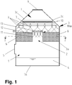
Figur 1 einen senkrechten Schnitt durch eine bevorzugte Variante einer Vorrichtung zur Behandlung von Abgas und -
Figur 2 einen waagerechten Schnitt durch die Vorrichtung derFigur 1 . - Wie aus den
Figuren 1 und2 ersichtlich umfasst eine Vorrichtung zur Behandlung von Abgas (oder Abluft) einen ersten Wäscher 1 und einen zweiten Wäscher 2, die parallel geschaltet sind. Die Wäscher 1, 2 sind also gleichzeitig von dem Abgas durchströmbar. Die Vorrichtung ist insgesamt als biologischer oder als chemischer Wäscher ausgebildet. - Der erste Wäscher 1 ist als Kolonnenwäscher ausgebildet und umfasst ein äußeres, im Wesentlichen dichtes Gehäuse 3, das einen zylindrischen Mantel 3a aufweist, an dessen unteren Ende ein flacher Boden 3b und am oberen Ende ein Deckel 3c in Form eines umgekehrten, sich nach oben verjüngenden Trichters befestigt sind. Ein unterer Bereich des Gehäuses 3 ist als Becken für eine Waschflüssigkeit 4 ausgebildet. Oberhalb dieses unteren Bereiches für die Waschflüssigkeit 4 ist an dem Mantel 3a ein Stutzen 5 zum Anschluss einer Abgaszuleitung für eine Zuführung des Abgases in die Vorrichtung angeordnet.
- In dem Gehäuse 3 ist oberhalb des Stutzens 5 eine Packung 6 angeordnet, die eine Vergrößerung einer Kontaktfläche zwischen dem Abgas und der Waschflüssigkeit 4 und gegebenenfalls für eine Ansiedlung von Mikroorganismen sorgt. Eine Höhe der Packung 6 ist entsprechend den Anforderungen (Art/Menge der Schadstoffe und geforderte Reinigungsleistung) bemessen und erstreckt sich innerhalb einer Höhe des Mantels 3a.
- Oberhalb der Packung 6 sind Mittel zum Verrieseln oder Versprühen der Waschflüssigkeit 4 auf die Packung 6 angeordnet. Die Mittel zum Verrieseln umfassen ein Rohrsystem 7 mit daran befestigten ersten Sprühdüsen 8 und gewährleisten eine gleichmäßige Verteilung der Waschflüssigkeit 4 auf einer Oberfläche der Packung 6.
- An einem oberen Ende des Deckels 3c ist ein Flansch 9 zum Anschluss einer Reingasleitung zum Ableiten des gereinigten Abgases angeordnet.
- Zwischen dem Flansch 9 und dem Rohrsystem 7 ist ein Tropfenabscheider 10 an dem Deckel 3c befestigt.
- Der zweite Wäscher 2 ist hier in und koaxial zu dem ersten Wäscher 1 befestigt. Der zweite Wäscher 2 ist hier als Sprühwäscher ausgeführt und umfasst ein Rohrstück 11, das sich im Wesentlichen über die Höhe der Packung 6 erstreckt, eine Vielzahl von zweiten Sprühdüsen 12 und ein Absperrorgan 13.
- Das Absperrorgan 13 ist an einem oberen Ende 11a des Rohrstücks 11 befestigt und als z.B. Klappe oder Schieber ausgebildet. Es weist einen elektromotorischen oder elektropneumatischen Antrieb auf.
- Die zweiten Sprühdüsen 12 sind innerhalb des Rohrstücks 11 mit möglichst kurzem Abstand zu dem Absperrorgan 13 angeordnet.
- Alternativ zu dem Sprühwäscher ist der zweite Wäscher 2 als Kolonnenwäscher mit geringer Schüttungshöhe ausgeführt. Dies ist besonders dann von Vorteil, wenn ein Verhältnis von minimaler Schadstofffracht zu maximaler Schadstofffracht größer als 1 zu 10 ist, also z.B. 1 zu 5 oder 1 zu 2.
- Alternativ zu der koaxialen Anordnung des zweiten Wäschers 2 ist dieser an beliebiger anderer Stelle in die Packung 6 eingesetzt, hierbei bevorzugt an dem Mantel 3a. Auch eine Anordnung außerhalb des ersten Wäschers 1 ist möglich, was aber Nachteile gegenüber der innerhalb des ersten Wäschers 1 aufweist.
- Querschnitte der Wäscher 1, 2 sind vorzugsweise kreisförmig und gleichartig ausgebildet oder alternativ vieleckig (z.B. als Rechteck oder als Oktogon), wobei eine Querschnittsform des ersten Wäschers 1 unterschiedlich von der des zweiten Wäschers 2 sein kann.
- Die Wäscher 1, 2 sind aus üblichen Materialien wie Stahl, Edelstahl oder Kunststoff gefertigt. Eine Auslegung des ersten Wäschers 1 erfolgt entsprechend den Vorschriften nach der maximalen Schadstofffracht. Der zweite Wäscher 2 ist entsprechend dem Verhältnis der maximalen zur minimalen Schadstofffracht dimensioniert.
- Im Betrieb wird das Abgas mittels eines nicht dargestellten Ventilators, dessen Antriebsmotor vorzugsweise geregelt, z.B. frequenzgeregelt ist, von einer Abluftquelle, z.B. aus einer Produktionszone abgezogen und durch die Abgasleitung in die Vorrichtung zum Behandeln des Abgases gefördert. Der Ventilator und sein Antrieb sind entsprechend einem maximal zu fördernden Abgasvolumen und gesamten Druckverlusten ausgelegt.
- Gegebenenfalls sind Mittel zum Konditionieren des Abgases angeordnet, um z.B. Temperatur und Feuchte des Abgases auf geeignete Werte einzustellen.
- Das Abgas wird durch die Vorrichtung geleitet und hierbei durch intensiven Kontakt mit der Waschflüssigkeit 4 auf geforderte Reingaswerte gereinigt. Die Waschflüssigkeit 4 ist mit Mikroorganismen (biologischer Wäscher) oder geeigneten Chemikalien (chemischer Wäscher) angereichert. Sie wird mittels einer Pumpe in einem Kreislauf aus dem Becken des ersten Wäschers 1 abgezogen, über Rohrleitungen den Sprühdüsen 8, 12 zugeführt, über der Packung 6 und in dem zweiten Wäscher 2 gleichmäßig verteilt und schwerkraftbedingt in dem Becken wieder aufgefangen. Das Reingas wird über z.B. einen Kamin in die Atmosphäre abgegeben.
- Bei der maximal zu reinigenden Schadstofffracht, die durch die maximale Schadstoffkonzentration und/oder die maximale Abgasmenge festgelegt ist, ist das Absperrorgan 13 geschlossen. Das Abgas wird weitgehend gleichmäßig verteilt von unten nach oben durch den ersten Wäscher 1 und damit auch durch die Packung 6 geleitet. Hierbei wird das Abgas bei hoher raumspezifischer Abbauleistung gereinigt, das heißt es wird weitestgehend von Schadstoffen befreit.
- Wenn die zu reinigende Schadstofffracht sinkt, das heißt bei fallender Schadstoffkonzentration und/oder Abgasmenge, wird das Absperrorgan 13 entsprechend der verminderten erforderlichen Abbauleistung teilweise oder ganz geöffnet. Ein Teil des Abgases wird daher durch den zweiten Wäscher 2 geleitet und bei geringerer raumspezifischer Abbauleistung gereinigt, während der Rest des Abgases weiter durch den ersten Wäscher 1 strömt. Der Druckverlust in der Vorrichtung sinkt entsprechend dem Öffnungsgrad des Absperrorgans 13 und der Ventilator wird entsprechend heruntergeregelt, was eine Verminderung des Stromverbrauchs zur Folge hat. Letztere beträgt bei voller Öffnung des Absperrorgans 13 bis zu 90 %.
- Bei Biowäschern kann zudem eine Vergrößerung des Druckverlustes durch Anstieg von Biomasse im Gesamtsystem erfolgen. Diese Vergrößerung kann durch entsprechendes teilweises Öffnen des Absperrorgans 13 ausgeglichen werden. Hierdurch ist es möglich, Reinigungsintervalle zu verlängern und so den Wartungsaufwand zu vermindern.
- Das Verstellen des Absperrorgans 13 und des Ventilators kann automatisch anhand von Messwerten, wobei entsprechende Mess- und Regelgeräte angeordnet sind, oder von Hand nach Erfahrungswerten erfolgen.
-
- 1
- erster Wäscher
- 2
- zweiter Wäscher
- 3
- Gehäuse
- 3a
- Mantel
- 3b
- Boden
- 3c
- Deckel
- 4
- Waschflüssigkeit
- 5
- Stutzen
- 6
- Packung
- 7
- Rohrsystem
- 8
- erste Sprühdüse
- 9
- Flansch
- 10
- Tropfenabscheider
- 11
- Rohr
- 11a
- oberes Ende
- 12
- zweite Sprühdüse
- 13
- Absperrorgan
Claims (8)
- Vorrichtung zum Behandeln von Abluft oder Abgas, umfassend
einen ersten Wäscher (1), der mit einer Packung (6) ausgebildet ist, die von der Abluft oder dem Abgas durchströmbar und von oben mit einer Waschflüssigkeit (4) berieselbar ist, und
einen zweiten Wäscher (2), der gegenüber dem ersten Wäscher (1) deutlich verringerte Druckverluste aufweist,
dadurch gekennzeichnet, dass der zweite Wäscher (2) mittels eines Absperrorgans (13) zumindest teilweise verschließbar ist. - Vorrichtung nach Anspruch 1, dadurch gekennzeichnet, dass der zweite Wäscher (2) innerhalb des ersten Wäschers (1) angeordnet ist.
- Vorrichtung nach Anspruch 1 oder 2, dadurch gekennzeichnet, dass das Absperrorgan (13) an einem oberen Ende (11a) des zweiten Wäschers (2) angeordnet ist.
- Vorrichtung nach Anspruch 2 oder 3, dadurch gekennzeichnet, dass eine senkrechte Längsachse des zweiten Wäschers (2) koaxial mit einer Längsachse des ersten Wäschers (1) ist.
- Vorrichtung nach einem der Ansprüche 1 bis 4, dadurch gekennzeichnet, dass der erste Wäscher (1) als Kolonnenwäscher ausgebildet ist.
- Vorrichtung nach einem der Ansprüche 1 bis 4, dadurch gekennzeichnet, dass der erste Wäscher (1) im Gegenstrom durchströmbar ist.
- Vorrichtung nach einem der Ansprüche 1 bis 6, dadurch gekennzeichnet, dass der zweite Wäscher (2) als Sprühwäscher ausgebildet ist.
- Vorrichtung nach einem der Ansprüche 1 bis 7, dadurch gekennzeichnet, dass der erste Wäscher (1) und der zweite Wäscher (2) parallel geschaltet sind.
Applications Claiming Priority (1)
| Application Number | Priority Date | Filing Date | Title |
|---|---|---|---|
| DE102018121876.1A DE102018121876B4 (de) | 2018-09-07 | 2018-09-07 | Vorrichtung zum Behandeln von Abluft oder Abgas |
Publications (1)
| Publication Number | Publication Date |
|---|---|
| EP3620226A1 true EP3620226A1 (de) | 2020-03-11 |
Family
ID=67439031
Family Applications (1)
| Application Number | Title | Priority Date | Filing Date |
|---|---|---|---|
| EP19188517.7A Pending EP3620226A1 (de) | 2018-09-07 | 2019-07-26 | Vorrichtung zum behandeln von abluft oder abgas |
Country Status (2)
| Country | Link |
|---|---|
| EP (1) | EP3620226A1 (de) |
| DE (1) | DE102018121876B4 (de) |
Citations (5)
| Publication number | Priority date | Publication date | Assignee | Title |
|---|---|---|---|---|
| EP0393014A2 (de) * | 1989-04-11 | 1990-10-17 | Peter J. Ing. Schmid | Einrichtung zur Behandlung von Gasen |
| WO1998032523A1 (en) * | 1997-01-24 | 1998-07-30 | Kvaerner Pulping Oy | Flue gas scrubber |
| EP0895800A1 (de) | 1997-08-08 | 1999-02-10 | Andritz-Patentverwaltungs-Gesellschaft m.b.H. | Absorptionskolonne |
| US20140116252A1 (en) * | 2011-05-02 | 2014-05-01 | Alstom Technology Ltd | Gas/liquid contacting vessel and the use thereof in a flue gas treatment system |
| US20140326140A1 (en) * | 2013-05-03 | 2014-11-06 | Fluor Technologies Corporation | Systems and methods for multi-celled gas processing |
Family Cites Families (5)
| Publication number | Priority date | Publication date | Assignee | Title |
|---|---|---|---|---|
| US1673732A (en) * | 1926-08-19 | 1928-06-12 | Frank E Gunter | Cooling device |
| FR2474887A1 (fr) * | 1980-02-05 | 1981-08-07 | Isman Marcel | Ensemble de traitement de lavage de gaz |
| GB8431597D0 (en) * | 1984-12-14 | 1985-01-30 | Ici Plc | Treatment of gas mixtures |
| AU6312898A (en) * | 1998-03-02 | 1999-09-20 | Kvaerner Ships Equipment A/S | Apparatus for reducing contaminants in a pulsating exhaust gas |
| JP6407079B2 (ja) * | 2015-03-25 | 2018-10-17 | 三菱日立パワーシステムズ株式会社 | 高湿分空気利用ガスタービンシステム及びその排ガス処理システム |
-
2018
- 2018-09-07 DE DE102018121876.1A patent/DE102018121876B4/de active Active
-
2019
- 2019-07-26 EP EP19188517.7A patent/EP3620226A1/de active Pending
Patent Citations (5)
| Publication number | Priority date | Publication date | Assignee | Title |
|---|---|---|---|---|
| EP0393014A2 (de) * | 1989-04-11 | 1990-10-17 | Peter J. Ing. Schmid | Einrichtung zur Behandlung von Gasen |
| WO1998032523A1 (en) * | 1997-01-24 | 1998-07-30 | Kvaerner Pulping Oy | Flue gas scrubber |
| EP0895800A1 (de) | 1997-08-08 | 1999-02-10 | Andritz-Patentverwaltungs-Gesellschaft m.b.H. | Absorptionskolonne |
| US20140116252A1 (en) * | 2011-05-02 | 2014-05-01 | Alstom Technology Ltd | Gas/liquid contacting vessel and the use thereof in a flue gas treatment system |
| US20140326140A1 (en) * | 2013-05-03 | 2014-11-06 | Fluor Technologies Corporation | Systems and methods for multi-celled gas processing |
Also Published As
| Publication number | Publication date |
|---|---|
| DE102018121876A1 (de) | 2020-03-12 |
| DE102018121876B4 (de) | 2020-03-19 |
Similar Documents
| Publication | Publication Date | Title |
|---|---|---|
| DE102006053910B4 (de) | Biowäscher | |
| CH624018A5 (de) | ||
| EP4355694A1 (de) | Vorrichtung zur aufbereitung von wasser | |
| DE9101439U1 (de) | Laborgaswäscher | |
| AT402201B (de) | Einrichtung zum feinblasigen eintrag von gasen in flüssigkeiten | |
| DE1242188B (de) | Verfahren und Vorrichtung zur Kontaktbehandlung von Gasen mit Fluessigkeiten | |
| EP3620226A1 (de) | Vorrichtung zum behandeln von abluft oder abgas | |
| CH639290A5 (en) | Apparatus for removing gaseous and solid pollutants and mists thereof from a waste gas | |
| DE4110550C2 (de) | Einrichtung zur Luftbefeuchtung mit Druckwasser | |
| DE69703630T2 (de) | Vorrichtung für die Beseitigung von Flüssigkeiten und/oder Verunreinigungen aus einem Gas | |
| DE2434664A1 (de) | Vorrichtung zur abscheidung von in gas befindlichen verunreinigungen in einer waschfluessigkeit | |
| DD301730A9 (de) | Reaktor zum entfernen von gasfoermigen schadstoffen und staeuben | |
| DE2225726B1 (de) | Siebvorrichtung | |
| DE2144382C3 (de) | Vorrichtung für die Naßreinigung von Gasen | |
| EP0579808A1 (de) | Vorrichtung zum filtern von gasen unter einsatz von biologischem filtermaterial | |
| DE202017002548U1 (de) | Anordnung zur Begasung von Flüssigkeiten mit einem rohrförmigen Begaser | |
| DE2403334A1 (de) | Klaeranlage | |
| DE102010009347B4 (de) | Vorrichtung zum Waschen von Rauchgas | |
| DE102016014455A1 (de) | Vorrichtung zur Belüftung einer Flüssigkeit | |
| CH677107A5 (de) | ||
| AT505752B1 (de) | Vorrichtung zum verandern des venturikehlenquerschnitts eines venturisystems | |
| DE102012021922B4 (de) | Filterwand zur Reinigung von Stallabluft und Abluftreinigungsanlage mit wenigstens einer Filterwand | |
| WO2010145755A1 (de) | Stoffaustauschkolonne | |
| AT222306B (de) | Hallenabluftreinigungsanlage | |
| EP4461706A1 (de) | Wasserbehandlungsgerät |
Legal Events
| Date | Code | Title | Description |
|---|---|---|---|
| PUAI | Public reference made under article 153(3) epc to a published international application that has entered the european phase |
Free format text: ORIGINAL CODE: 0009012 |
|
| STAA | Information on the status of an ep patent application or granted ep patent |
Free format text: STATUS: THE APPLICATION HAS BEEN PUBLISHED |
|
| AK | Designated contracting states |
Kind code of ref document: A1 Designated state(s): AL AT BE BG CH CY CZ DE DK EE ES FI FR GB GR HR HU IE IS IT LI LT LU LV MC MK MT NL NO PL PT RO RS SE SI SK SM TR |
|
| AX | Request for extension of the european patent |
Extension state: BA ME |
|
| STAA | Information on the status of an ep patent application or granted ep patent |
Free format text: STATUS: REQUEST FOR EXAMINATION WAS MADE |
|
| 17P | Request for examination filed |
Effective date: 20200911 |
|
| RBV | Designated contracting states (corrected) |
Designated state(s): AL AT BE BG CH CY CZ DE DK EE ES FI FR GB GR HR HU IE IS IT LI LT LU LV MC MK MT NL NO PL PT RO RS SE SI SK SM TR |
|
| STAA | Information on the status of an ep patent application or granted ep patent |
Free format text: STATUS: EXAMINATION IS IN PROGRESS |
|
| 17Q | First examination report despatched |
Effective date: 20231016 |