EP3620122A1 - Drive unit, surgical instrument for medical use, and operation system - Google Patents
Drive unit, surgical instrument for medical use, and operation system Download PDFInfo
- Publication number
- EP3620122A1 EP3620122A1 EP18795246.0A EP18795246A EP3620122A1 EP 3620122 A1 EP3620122 A1 EP 3620122A1 EP 18795246 A EP18795246 A EP 18795246A EP 3620122 A1 EP3620122 A1 EP 3620122A1
- Authority
- EP
- European Patent Office
- Prior art keywords
- gear
- section
- treatment tool
- medical treatment
- elongated element
- Prior art date
- Legal status (The legal status is an assumption and is not a legal conclusion. Google has not performed a legal analysis and makes no representation as to the accuracy of the status listed.)
- Withdrawn
Links
Images


Classifications
-
- A—HUMAN NECESSITIES
- A61—MEDICAL OR VETERINARY SCIENCE; HYGIENE
- A61B—DIAGNOSIS; SURGERY; IDENTIFICATION
- A61B34/00—Computer-aided surgery; Manipulators or robots specially adapted for use in surgery
- A61B34/30—Surgical robots
-
- A—HUMAN NECESSITIES
- A61—MEDICAL OR VETERINARY SCIENCE; HYGIENE
- A61B—DIAGNOSIS; SURGERY; IDENTIFICATION
- A61B17/00—Surgical instruments, devices or methods, e.g. tourniquets
- A61B17/28—Surgical forceps
- A61B17/29—Forceps for use in minimally invasive surgery
-
- A—HUMAN NECESSITIES
- A61—MEDICAL OR VETERINARY SCIENCE; HYGIENE
- A61B—DIAGNOSIS; SURGERY; IDENTIFICATION
- A61B17/00—Surgical instruments, devices or methods, e.g. tourniquets
- A61B17/28—Surgical forceps
- A61B17/29—Forceps for use in minimally invasive surgery
- A61B17/2909—Handles
-
- A—HUMAN NECESSITIES
- A61—MEDICAL OR VETERINARY SCIENCE; HYGIENE
- A61B—DIAGNOSIS; SURGERY; IDENTIFICATION
- A61B34/00—Computer-aided surgery; Manipulators or robots specially adapted for use in surgery
- A61B34/30—Surgical robots
- A61B34/37—Master-slave robots
-
- A—HUMAN NECESSITIES
- A61—MEDICAL OR VETERINARY SCIENCE; HYGIENE
- A61B—DIAGNOSIS; SURGERY; IDENTIFICATION
- A61B34/00—Computer-aided surgery; Manipulators or robots specially adapted for use in surgery
- A61B34/70—Manipulators specially adapted for use in surgery
- A61B34/71—Manipulators operated by drive cable mechanisms
-
- A—HUMAN NECESSITIES
- A61—MEDICAL OR VETERINARY SCIENCE; HYGIENE
- A61B—DIAGNOSIS; SURGERY; IDENTIFICATION
- A61B90/00—Instruments, implements or accessories specially adapted for surgery or diagnosis and not covered by any of the groups A61B1/00 - A61B50/00, e.g. for luxation treatment or for protecting wound edges
- A61B90/36—Image-producing devices or illumination devices not otherwise provided for
- A61B90/361—Image-producing devices, e.g. surgical cameras
-
- A—HUMAN NECESSITIES
- A61—MEDICAL OR VETERINARY SCIENCE; HYGIENE
- A61B—DIAGNOSIS; SURGERY; IDENTIFICATION
- A61B90/00—Instruments, implements or accessories specially adapted for surgery or diagnosis and not covered by any of the groups A61B1/00 - A61B50/00, e.g. for luxation treatment or for protecting wound edges
- A61B90/50—Supports for surgical instruments, e.g. articulated arms
-
- B—PERFORMING OPERATIONS; TRANSPORTING
- B25—HAND TOOLS; PORTABLE POWER-DRIVEN TOOLS; MANIPULATORS
- B25J—MANIPULATORS; CHAMBERS PROVIDED WITH MANIPULATION DEVICES
- B25J17/00—Joints
-
- A—HUMAN NECESSITIES
- A61—MEDICAL OR VETERINARY SCIENCE; HYGIENE
- A61B—DIAGNOSIS; SURGERY; IDENTIFICATION
- A61B17/00—Surgical instruments, devices or methods, e.g. tourniquets
- A61B2017/00477—Coupling
-
- A—HUMAN NECESSITIES
- A61—MEDICAL OR VETERINARY SCIENCE; HYGIENE
- A61B—DIAGNOSIS; SURGERY; IDENTIFICATION
- A61B17/00—Surgical instruments, devices or methods, e.g. tourniquets
- A61B17/28—Surgical forceps
- A61B17/29—Forceps for use in minimally invasive surgery
- A61B2017/2901—Details of shaft
- A61B2017/2902—Details of shaft characterized by features of the actuating rod
- A61B2017/2903—Details of shaft characterized by features of the actuating rod transferring rotary motion
-
- A—HUMAN NECESSITIES
- A61—MEDICAL OR VETERINARY SCIENCE; HYGIENE
- A61B—DIAGNOSIS; SURGERY; IDENTIFICATION
- A61B17/00—Surgical instruments, devices or methods, e.g. tourniquets
- A61B17/28—Surgical forceps
- A61B17/29—Forceps for use in minimally invasive surgery
- A61B17/2909—Handles
- A61B2017/2912—Handles transmission of forces to actuating rod or piston
- A61B2017/2923—Toothed members, e.g. rack and pinion
-
- A—HUMAN NECESSITIES
- A61—MEDICAL OR VETERINARY SCIENCE; HYGIENE
- A61B—DIAGNOSIS; SURGERY; IDENTIFICATION
- A61B17/00—Surgical instruments, devices or methods, e.g. tourniquets
- A61B17/28—Surgical forceps
- A61B17/29—Forceps for use in minimally invasive surgery
- A61B2017/2926—Details of heads or jaws
- A61B2017/2927—Details of heads or jaws the angular position of the head being adjustable with respect to the shaft
-
- A—HUMAN NECESSITIES
- A61—MEDICAL OR VETERINARY SCIENCE; HYGIENE
- A61B—DIAGNOSIS; SURGERY; IDENTIFICATION
- A61B17/00—Surgical instruments, devices or methods, e.g. tourniquets
- A61B17/28—Surgical forceps
- A61B17/29—Forceps for use in minimally invasive surgery
- A61B2017/2926—Details of heads or jaws
- A61B2017/2932—Transmission of forces to jaw members
- A61B2017/2938—Independently actuatable jaw members, e.g. two actuating rods
-
- A—HUMAN NECESSITIES
- A61—MEDICAL OR VETERINARY SCIENCE; HYGIENE
- A61B—DIAGNOSIS; SURGERY; IDENTIFICATION
- A61B17/00—Surgical instruments, devices or methods, e.g. tourniquets
- A61B17/28—Surgical forceps
- A61B17/29—Forceps for use in minimally invasive surgery
- A61B2017/2926—Details of heads or jaws
- A61B2017/2932—Transmission of forces to jaw members
- A61B2017/2943—Toothed members, e.g. rack and pinion
-
- A—HUMAN NECESSITIES
- A61—MEDICAL OR VETERINARY SCIENCE; HYGIENE
- A61B—DIAGNOSIS; SURGERY; IDENTIFICATION
- A61B34/00—Computer-aided surgery; Manipulators or robots specially adapted for use in surgery
- A61B34/30—Surgical robots
- A61B2034/301—Surgical robots for introducing or steering flexible instruments inserted into the body, e.g. catheters or endoscopes
-
- A—HUMAN NECESSITIES
- A61—MEDICAL OR VETERINARY SCIENCE; HYGIENE
- A61B—DIAGNOSIS; SURGERY; IDENTIFICATION
- A61B34/00—Computer-aided surgery; Manipulators or robots specially adapted for use in surgery
- A61B34/30—Surgical robots
- A61B2034/305—Details of wrist mechanisms at distal ends of robotic arms
-
- A—HUMAN NECESSITIES
- A61—MEDICAL OR VETERINARY SCIENCE; HYGIENE
- A61B—DIAGNOSIS; SURGERY; IDENTIFICATION
- A61B34/00—Computer-aided surgery; Manipulators or robots specially adapted for use in surgery
- A61B34/70—Manipulators specially adapted for use in surgery
- A61B34/71—Manipulators operated by drive cable mechanisms
- A61B2034/715—Cable tensioning mechanisms for removing slack
-
- A—HUMAN NECESSITIES
- A61—MEDICAL OR VETERINARY SCIENCE; HYGIENE
- A61B—DIAGNOSIS; SURGERY; IDENTIFICATION
- A61B90/00—Instruments, implements or accessories specially adapted for surgery or diagnosis and not covered by any of the groups A61B1/00 - A61B50/00, e.g. for luxation treatment or for protecting wound edges
- A61B90/03—Automatic limiting or abutting means, e.g. for safety
- A61B2090/033—Abutting means, stops, e.g. abutting on tissue or skin
- A61B2090/034—Abutting means, stops, e.g. abutting on tissue or skin abutting on parts of the device itself
-
- A—HUMAN NECESSITIES
- A61—MEDICAL OR VETERINARY SCIENCE; HYGIENE
- A61B—DIAGNOSIS; SURGERY; IDENTIFICATION
- A61B46/00—Surgical drapes
- A61B46/10—Surgical drapes specially adapted for instruments, e.g. microscopes
Definitions
- the invention relates to a drive unit for operating distal end parts, such as grasping forceps used in surgeries, a medical treatment tool, and a surgical system.
- a surgery assistant robot includes a patient-side apparatus provided with manipulators, for example. Suitable medical treatment tools are attached to the manipulators and are remotely operated for surgery.
- Patent Literature 1 (Specification of US Patent No. 6394998 ) discloses a medical treatment tool that uses plural spools as a driving mechanism to wind or unwind flexible elongated elements such as wire for moving the distal end parts, such as grasping forceps.
- Patent Literature 1 Specification of US Patent No. 6394998
- Such a surgery assistant robot requires complicated work to assemble medical treatment tools, such as winding flexible members extending from a distal end part to the driving mechanism, around spools, and adjusting the tension of the flexible members while fixing the spools with screws or the like.
- the invention was made to solve the aforementioned problem.
- An object thereof is to provide a drive unit that facilitates assembly of a medical treatment tool, the medical treatment tool, and a surgical system.
- a drive unit for driving elongated elements to operate a distal end part of a medical treatment tool, the drive unit including: a first gear that rotates about a first axis; a second gear that rotates about a second axis extending in a direction perpendicular to the first axis; and a third gear that rotates about a third axis extending in a direction perpendicular to the first axis.
- the elongated elements include: a first elongated element that is rigid and meshes with the second gear; and a second elongated element that is rigid and meshes with the third gear, and the second and third gears mesh with the first gear.
- the distal end part is operated in such a manner that as the first gear rotates, the first elongated element moves in a longitudinal direction of the medical treatment tool while the second elongated element moves in a direction opposite to the direction in which the first elongated element moves.
- a medical treatment tool to achieve the aforementioned object includes: the drive unit; the distal end part that is operated by the first and second elongated elements; and a shaft that accommodates the first and second elongated elements.
- a medical treatment tool to achieve the aforementioned object includes: a driving mechanism that includes three of the drive units; the distal end part that is controlled with three pairs of the first and second elongated elements; and a shaft that accommodates the three pairs of the first and second elongated elements.
- a surgical system to achieve the aforementioned object includes: the medical treatment tool; and a manipulator including the transmitter member that engages with the receiver member.
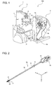
- Fig. 1 is a view illustrating a configuration of a surgical system.
- a surgical system 300 is, for example, a system in which a surgeon Q uses a patient-side apparatus 1 to perform an endoscopic surgery for a subject P, including a human or an animal.
- the surgical system 300 includes the patient-side apparatus 1 and an operation apparatus 2 for operating the patient-side apparatus 1.
- the surgeon Q inputs a movement instruction for the patient-side apparatus 1 into the operation apparatus 2, and the operation apparatus 2 transmits an instruction signal including the inputted movement instruction, to the patient-side apparatus 1.
- the patient-side apparatus 1 receives the instruction signal transmitted from the operation apparatus 2 and operates an endoscopic assembly 4a and a medical treatment tool 4b, which are connected to distal ends of the patient-side apparatus 1, based on the movement instruction included in the received instruction signal.
- the operation apparatus 2 includes an operation input section 5, which includes an operation manipulator 5a and an operation pedal 5b, and a monitor 5c.
- the monitor 5c displays images captured by the endoscopic assembly 4a.
- the operation manipulator 5a and operation pedal 5b are equipment for the surgeon Q to input a movement instruction.
- the surgeon Q inputs a movement instruction to the operation apparatus 2 by operating the operation manipulator 5a and operation pedal 5b while watching the diseased area in the image displayed on the monitor 5c.
- the operation apparatus 2 transmits an instruction signal including the inputted movement instruction, to the patient-side apparatus 1 via wire or wirelessly.
- the patient-side apparatus 1 includes: a positioner 7; a platform 8, which is attached to the top end of the positioner 7; manipulators 3, which are detachably attached to the platform 8; the endoscopic assembly 4a; the medical treatment tool 4b; and a controller 6 that controls movement of the patient-side apparatus 1.
- the endoscopic assembly 4a and medical treatment tool 4b are attached to the respective manipulators 3.
- the medical treatment tool 4b is grasper forceps (a grasper), a needle driver, scissors, or the like.
- the controller 6 receives an instruction signal from the operation apparatus 2 and operates the endoscopic assembly 4a and medical treatment tool 4b based on the received instruction signal.
- the controller 6 receives an instruction signal and based on a movement instruction included in the instruction signal, first controls the positioner 7 for positioning of the platform 8.
- the controller 6 also positions the manipulators 3 so that the endoscopic assembly 4a and medical treatment tool 4b are located at predetermined initial positions relative to a not-illustrated cannula placed on the body surface of the subject P.
- the controller 6 Based on the movement instruction, the controller 6 then outputs a control signal to drive the endoscopic assembly 4a or medical treatment tool 4b, to the endoscopic assembly 4a or medical treatment tool 4b via the manipulators 3.
- the endoscopic assembly 4a and medical treatment tool 4b then operate in accordance with the control signals received from the controller 6.
- Fig. 2 is a view illustrating the configuration of the medical treatment tool.
- the medical treatment tool 4b includes a distal end part 11, a shaft 12, elongated elements 13 to operate the distal end part 11, and a driving mechanism 15 to drive the elongated elements 13.
- the driving mechanism 15 is activated by a driving device 16 including a driving source.
- the driving device 16 is a part of the corresponding manipulator 3 and is provided at the distal end of the manipulator 3, for example.
- elongated elements collectively means rods, wires, cables, or the like. Rigid ones, such as rods, are referred to as rigid elongated elements while flexible ones, such as wire and cable, are referred to as flexible elongated elements. In order to describe elongated elements without distinguishing rigid and flexible ones, the elongated elements, including rigid and flexible ones, are collectively referred to as elongated elements.
- the distal end part 11 includes two jaws 21 and 22, for example. These two jaws 21 and 22 have the same shape to minimize the manufacturing cost.
- the shaft 12 includes a cylindrical shape extending in the longitudinal direction of the medical treatment tool 4b and is rotatable in the direction of arrow A. The shaft 12 is thus rotatable about the axis along the longitudinal direction thereof.
- rods for example, are rigid members accommodated in the shaft 12.
- wires for example, are flexible members which are made of tungsten, stainless, or the like and have sufficient strength, flexibility, and durability.
- the driving mechanism 15 detachably connects to the corresponding manipulator 3 in the patient-side apparatus 1 illustrated in Fig. 1 .
- the driving mechanism 15 receives a control signal from the patient-side apparatus 1 via the manipulator 3 and moves the elongated elements 13 in the longitudinal direction of the medical treatment tool 4b in accordance with the control signal.
- the detailed configuration of the driving mechanism 15 is described later.
- Fig. 3 is a perspective view illustrating the configuration of the distal end part of the medical treatment tool illustrated in Fig. 2 .
- the distal end part 11 includes a wrist section 23, in addition to the jaws 21 and 22.
- the wrist section 23 is attached to an end section 12a of the shaft 12 through a joint section 31.
- the wrist section 23 is pivotable about the joint section 31 in the direction of arrow B.
- the jaws 21 and 22 are attached to the wrist section 23 through a joint section 32.
- the jaws 21 and 22 include finger sections 24a and 24b and pulley sections 25a and 25b, respectively.
- the finger sections 24a and 24b are pivotable about the joint section 32 in the direction of arrow C.
- the pulley sections 25a and 25b are rotatable about the joint section 32.
- the direction that the joint section 31 extends is preferably different from the direction that the joint section 32 extends.
- the direction that the joint section 31 extends is at 90 degrees to the direction that the joint section 32 extends.
- the direction that the joint section 31 extends is the direction of Y axis; the direction that the joint section 32 extends is the direction of X axis; and the longitudinal direction of the shaft 12 is the direction of Z axis.
- Fig. 4 is a side view illustrating the configuration of the distal end part of the medical treatment tool illustrated in Fig. 3 .
- free ends 21a and 22a of the jaws 21 and 22 pivot about the joint section 32 as indicated by arrows C1 and C2, respectively.
- the free ends 21a and 22a thereby move close to and away from each other or pivot in the same direction.
- the distal end part 11 further includes a first pulley section 41, a second pulley section 42, a third pulley section 43, a fourth pulley section 44, and a fifth pulley section 45, in addition to the jaws 21 and 22 and wrist section 23.
- Each of the first to fourth pulley sections 41 to 44 includes an inner pulley and an outer pulley.
- the first, second, and fifth pulley sections 41, 42, and 45 are attached to the end section 12a through the joint section 31 and are rotatable about the joint section 31.
- the third pulley section 43 is attached to the wrist section 23 through a joint section 33 and is rotatable about the joint section 33.
- the fourth pulley section 44 is attached to the wrist section 23 through a joint section 34 and is rotatable about the joint section 34.
- the planes of rotation of the first pulley section 41 and third pulley section 43 lie in the substantially same plane.
- the planes of rotation of the second pulley section 42 and fourth pulley section 44 lie in the substantially same plane.
- Fig. 5 is a view illustrating the configuration of a combination of rods and a wire as an example of the elongated element used in the medical treatment tool.
- each elongated element 13 includes a first rod (a first rigid elongated element) 13a, a second rod (a second rigid elongated element) 13b, and a wire 14.
- the first and second rods 13a and 13b individually connect to the wire 14.
- the wire 14 is provided with a thick section 14a near the center thereof.
- first and second rods 13a and 13b connect to the same wire 14.
- the wire 14 connected to the first rod 13a may be a different member from the wire 14 connected to the second rod 13b.
- the first and second rods 13a and 13b include toothed sections 20a and 20b at ends on the opposite side to the wire 14.
- the toothed sections 20a and 20b mesh with a gear of the driving mechanism 15.
- the medical treatment tool 4b illustrated in Fig. 2 includes three sets of the first rod 13a, second rod 13b, and wire 14, for example.
- the three first rods 13a included in the three sets are referred to as first rods 131a, 132a, and 133a.
- the three second rods 13b included in the three sets are referred to as second rods 131b, 132b, and 133b.
- the three wires 14 included in the three sets are referred to as wires 141, 142, and 143.
- the wire 141 connects the first and second rods 131a and 131b.
- the wire 142 connects the first and second rods 132a and 132b.
- the wire 143 connects the first and second rods 133a and 133b.
- Fig. 6 is a view illustrating an example of wound wires.
- arrow Z1 indicates the positive direction of the Z axis while arrow Z2 indicates the negative direction of the Z axis.
- the wire 141 is wound around the outer pulley of the first pulley section 41 and the outer pulley of the third pulley section 43, then wound around the pulley section 25b of the jaw 22, and then wound around the inner pulley of the fourth pulley section 44 and the inner pulley of the second pulley section 42.
- the thick section 14a of the wire 141 illustrated in Fig. 5 is fitted to a not-illustrated recess formed in the finger section 24b of the jaw 22 illustrated in Fig. 6 , for example.
- the wire 141 is thereby fixed to the jaw 22, so that the jaw 22 moves through the wire 141 being driven.
- the wire 142 is wound around the inner pulley of the first pulley section 41 and the inner pulley of the third pulley section 43, wound around the pulley section 25a of the jaw 22, and then wound around the outer pulley of the fourth pulley section 44 and the outer pulley of the second pulley section 42.
- the thick section 14a of the wire 142 illustrated in Fig. 5 is fitted to a not-illustrated recess formed in the finger section 24a of the jaw 21 illustrated in Fig. 6 , for example.
- the wire 142 is thereby fixed to the jaw 21, so that the jaw 21 moves through the wire 142 being driven.
- the wire 143 is wound around the fifth pulley section 45.
- the thick section 14a of the wire 143 illustrated in Fig. 5 is fitted to a not-illustrated recess formed in the wrist section 23 illustrated in Fig. 6 , for example.
- the wire 143 is thereby fixed to the wrist section 23, so that the wrist section 23 moves through the wire 143 being driven.
- the jaws 22 and 21 and wrist section 23 of the distal end part 11 move through the wires 141, 142, and 143 as the flexible member being driven, respectively, so that the distal end part 11 operates smoothly in a desired direction.
- the jaw 22 pivots about the joint section 32 in the direction of arrow C2a. In other words, the jaw 22 pivots towards the jaw 21 in the circumferential direction of a circle centered at the joint section 32.
- the jaw 22 pivots about the joint section 32 in the direction of arrow C2b. In other words, the jaw 22 pivots away from the jaw 21 in the circumferential direction of a circle centered at the joint section 32.
- the jaw 21 pivots about the joint section 32 in the direction of arrow C1a. In other words, the jaw 21 pivots away from the jaw 22 in the circumferential direction of a circle centered at the joint section 32.
- the jaw 21 pivots about the joint section 32 in the direction of arrow C1b. In other words, the jaw 21 pivots toward the jaw 22 in the circumferential direction of a circle centered at the joint section 32.
- the jaws 21 and 22 both pivot in the circumferential direction of a circle centered at the joint section 32, as indicated by arrow D1.
- the jaw 21 pivots in the direction of arrow C1a while the jaw 22 pivots in the direction of arrow C2a.
- the jaws 21 and 22 both pivot in the circumferential direction of a circle centered at the joint section 32, as indicated by arrow D2.
- the jaw 21 pivots in the direction of arrow C1b while the jaw 22 pivots in the direction of arrow C2b.
- the wrist section 23 pivots about the joint section 31 in the direction of arrow B2.
- the wrist section 23 pivots counterclockwise in the circumferential direction of a circle centered at the joint section 31, as seen along the Y axis from the negative side toward the positive side.
- the wrist section 23 pivots about the joint section 31 in the direction of arrow B1.
- the wrist section 23 pivots clockwise in the circumferential direction of a circle centered at the joint section 31, as seen along the Y axis from the negative side toward the positive side.
- the distal end part 11 of the medical treatment tool 4b is not limited to the configuration in which the distal end part 11 is operated by the elongated elements 13 each including a combination of rods and wire and may have a configuration in which the distal end part 11 is operated by elongated elements each including only rods.
- Fig. 7 is a view illustrating the configuration of a distal end part of a modification of a medical treatment tool.
- the distal end part 11 includes two jaws 71 and 72 and two gears 81 and 82, for example.
- the two jaws 71 and 72 and two gears 81 and 82 are attached to the end section 12a of the shaft 12 illustrated in Fig. 3 , through a joint section 73.
- the gears 81 and 82 are rotatable about the joint section 73, and the jaws 71 and 72 are pivotable about the joint section 73 in the direction of arrow D1 or D2.
- the medical treatment tool 4b includes first rods (first rigid elongated elements) 91a and 92a and second rods (second rigid elongated elements) 91b and 92b instead of the rods and wires.
- the first and second rods 91a and 91b are provided so that teeth formed at respective ends face each other on either side of the gear 81. As the first and second rods 91a and 91b move in opposing directions along the Z axis, the gear 81 rotates about the joint section 73. The jaw 71 thereby pivots about the joint section 73 together with the gear 81.
- the first and second rods 92a and 92b are provided so that teeth formed at respective ends face each other on either side of the gear 82. As the first and second rods 92a and 92b move in opposing directions along the Z axis, the gear 82 rotates about the joint section 73. The jaw 72 thereby pivots about the joint section 73 together with the gear 82.
- first rods 91a and 92a and second rods 91b and 92b directly connect to the distal end part 11 in such a manner, no work is necessary to adjust wire tension during the assembly process of the medical treatment tool 4b or other processes. It is therefore possible to further facilitate assembly of the medical treatment tool 4b and the like.
- Fig. 8 is a perspective view illustrating the configurations of the driving mechanism and driving device.
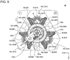
- Fig. 9 is a front view illustrating the configuration of the driving mechanism illustrated in Fig. 8.
- Figs. 8 and 9 do not illustrate a housing that covers the driving mechanism 15 for explanation of the driving mechanism 15.
- the driving mechanism 15 includes plural drive units 101.
- Each drive unit 101 includes a first gear 61; a second gear 62, which meshes with the first rod 13a; a third gear 63, which meshes with the second rod 13b; and a receiver member as a part of a transmission section 75 to rotate the first gear 61.
- the transmission section 75 is described in detail later.
- the driving device 16 includes plural actuators 50.
- Each actuator 50 receives a control signal from the patient-side apparatus 1 illustrated in Fig. 1 , through the manipulator 3 and rotates the corresponding receiver member of the transmission section 75 in accordance with the control signal.
- the receiver member rotates itself to rotate the corresponding first gear 61.
- the second and third gears 62 and 63 have substantially the same shape.
- the first gear 61 rotates about a first axis 161 parallel to the longitudinal direction of the medical treatment tool 4b.
- the second gear 62 rotates about a second axis 162, which extends perpendicularly to the first axis 161.
- the third gear 63 rotates about a third axis 163, which extends perpendicularly to the first axis 161.
- the first gear 61 is a substantially-conical bevel gear, for example.
- the first gear 61 includes teeth in the conical surface.
- Each of the second and third gears 62 and 63 is a gear including a combination of a substantially-conical bevel gear and a cylindrical gear, for example.
- teeth are formed in the lateral surface of the conical part, and teeth are formed in the side surface of the cylindrical part.
- the second and third gears 62 and 63 mesh with the first gear 61.
- the teeth in the lateral surface of the second gear 62 and the teeth in the lateral surface of the third gear 63 mesh with the teeth in the first gear 61.
- the second and third gears 62 and 63 rotate in the same direction as seen from the first gear 61 side. Specifically, when the second gear 62 rotates clockwise as seen from the first gear 61 side, the third gear 63 also rotates clockwise as seen from the first gear 61.
- the first, second, and third gears 61, 62, and 63 are all bevel gears.
- the first gear 61 may be a crown gear while the second and third gears 62 and 63 are spur gears.
- Such a configuration also implements the same rotary movement as described above.
- the teeth formed in the side surface of the cylindrical part of the second gear 62 mesh with the toothed section 20a formed in the first rod 131a illustrated in Fig. 5 .
- the second gear 62 and first rod 131a constitute a rack-and-pinion structure.
- the first rod 131a moves in the longitudinal direction of the shaft 12 as the second gear 62 rotates.
- the teeth formed in the side surface of the cylindrical part of the third gear 63 mesh with the toothed section 20b, which is formed in the second rod 131b illustrated in Fig. 5 .
- the third gear 63 and second rod 131b constitute a rack-and-pinion structure.
- the second rod 131b moves in the longitudinal direction of the shaft 12 as the third gear 63 rotates.
- the first and second rods 131a and 131b are positioned near the center of the shaft 12.
- the first rod 131a and second rod 131b are positioned so that the position of engagement of the first rod 131a in the side surface of the disk of the second gear 62 as seen from the first gear 61 is opposite to the position of engagement of the second rod 131b in the side surface of the disk of the third gear 63 as seen from the first gear 61.
- the second gear 62 meshes with the first rod 131a on the right side as seen from the first gear 61 while the third gear 63 meshes with the second rod 131b on the left side as seen from the first gear 61.
- the first and second rods 131a and 131b thereby move in opposing directions along the longitudinal axis of the shaft 12 as the first gear 61 rotates.
- Such a configuration that the distal end part 11 is operated by using the first and second rods 131a and 131b that move in opposing directions as the first gear 61 rotates eliminates the need for work to wind the wire 14 around the driving mechanism 15 and adjust the tension thereof. It is therefore possible to further facilitate assembly of the medical treatment tool 4b.
- the elongated elements do not stretch even after long-term use, unlike flexible members such as wire, thus ensuring strength and durability.
- the driving mechanism 15 includes three drive units 101, each including the aforementioned first, second, and third gears 61, 62, and 63, for example.
- the three drive units 101 are referred to as drive units 101A, 101B, and 101C.
- the drive units 101 A, 101B, and 101C are positioned at substantially equal intervals in the circumferential direction of the shaft 12.
- the rotational axes of the first gears 61 of the drive units 101 are positioned at substantially equal intervals in particular.
- the first, second, and third gears 61, 62, and 63 included in the drive unit 101A are referred to as first, second, and third gears 61A, 62A, and 63A, respectively.
- the first, second, and third gears 61, 62, and 63 included in the drive unit 101B are referred to as first, second, and third gears 61B, 62B, and 63B, respectively.
- the first, second, and third gears 61, 62, and 63 included in the drive unit 101C are referred to as first, second, and third gears 61C, 62C, and 63C, respectively.
- the second and third gears 62A and 63A mesh with the first gear 61A.
- the second gear 62A meshes with the first rod 131a to operate the jaw 22 while the third gear 63A meshes with the second rod 131b to operate the jaw 22.
- the second and third gears 62B and 63B mesh with the first gear 61B.
- the second gear 62B meshes with the first rod 132a to operate the jaw 21 while the third gear 63B meshes with the second rod 132b to control the jaw 21.
- the second and third gears 62C and 63C mesh with the first gear 61C.
- the second gear 62C meshes with the first rod 133a to operate the wrist section 23 while the third gear 63C meshes with the second rod 133b to operate the wrist section 23.
- the driving device 16 includes four actuators 51, 52, 53, and 54 as the plural actuators 50, for example.
- the actuators 51, 52, 53, and 54 are servo motors, for example.
- the driving device 16 further includes a fourth gear 64, a fifth gear 65, a rotation mechanism 76, and a transmitter member 78 as a part of the transmission section 75.
- the fourth gear 64 rotates the first gear 61C through the transmission section 75.
- the fifth gear 65 meshes with the fourth gear 64.
- the actuator 51 rotates the first gear 61A through the transmission section 75 in accordance with a control signal from the patient-side apparatus 1 (illustrated in Fig. 1 ).
- the actuator 52 rotates the first gear 61B through the transmission section 75 in accordance with a control signal from the patient-side apparatus 1 in a similar manner to the actuator 51.
- the actuator 53 rotates the fifth gear 65 in accordance with a control signal from the patient-side apparatus 1.
- the fourth gear 64 rotates to rotate the first gear 61C through the transmission section 75.
- the actuator (a rotation mechanism driving actuator) 54 rotates a sixth gear 66, which constitutes the rotation mechanism 76, in accordance with a control signal from the patient-side apparatus 1.
- the sixth gear 66 rotates, the whole medical treatment tool 4b rotates about an axis parallel to the longitudinal axis (a shaft axis) of the shaft 12.
- the rotation mechanism 76 includes a fixed rotational axis adjustment gear (a sun gear, not illustrated) having a disk shape, in addition to the sixth gear 66.
- the side surface of the disk of the rotational axis adjustment gear meshes with the sixth gear 66.
- the central axis of the rotational axis adjustment gear coincides with the shaft axis.
- the sixth gear 66 rotates about its own axis while revolving around the rotational axis adjustment gear (functioning as a planet gear), so that the distal end part 11 of the medical treatment tool 4b rotates about the shaft axis.
- the rotation mechanism 76 needs to have a configuration that allows the medical treatment tool 4b to rotate about an axis parallel to the longitudinal direction (the shaft axis) of the shaft 12.
- the rotation mechanism 76 unnecessarily employs such a planetary gear mechanism.
- Fig. 10 is a perspective view illustrating the configuration of the transmission section.
- the transmission section 75 includes a receiver member 77 of the driving mechanism 15; and a transmitter member 78 of the driving device 16.
- the receiver member 77 connects to the first gear 61 through a rotation section 111.
- the receiver member 77 engages with the transmitter member 78 and rotates when the transmitter member 78 rotates.
- the transmitter member 78 is rotationally driven directly or indirectly by the corresponding actuator 50 illustrated Fig. 8 .
- the receiver member 77 includes a rotatable disk section 201. In the main surface of the disk section 201, an engaged section 202 is formed.
- the transmitter member 78 includes an engaging section 221, which is engageable with the engaged section 202 of the receiver member 77.
- the engaged section 202 of the receiver member 77 is a groove or a recess, for example.
- the engaged section 202 has a continuous pattern which is not symmetric about any line through the center of the main surface.
- the engaging section 221 of the transmitter member 78 is a protrusion, for example.
- the engaging section 221 has a continuous pattern which is not symmetric about any line through the center of the main surface, similarly to the engaged section 202.
- the direction of the receiver member 77 to drive the distal end part 11 illustrated in Fig. 2 is determined uniquely among 360 degrees.
- the patterns of the engaging section 221 and engaged section 202 are linear, for example.
- the pattern of the engaging section 221 passes through the center of the main surface of the transmitter member 78 while the pattern of the engaged section 202 passes through the center of the main surface of the disk section 201.
- the engaging section 221 is tapered so as to gradually decrease in width toward the receiver member 77 in the direction of the Z axis, which is perpendicular to the main surface of the transmitter member 78, that is, in the negative direction of the Z axis illustrated in Fig. 10 .
- the transmitter member 78 is energized toward the receiver member 77, that is, in the negative direction of the Z axis illustrated in Fig. 10 , by a spring or the like. Some misalignment in the positional relationship between the engaged section 202 and the engaging section 221 is corrected during assembly thereof so that the engaging section 221 fits into the engaged section 202. This further facilitates the work to engage the engaging section 221 and the engaged section 202.
- the engaging section 221 may be a groove or a recess instead of a protrusion.
- the engaged section 202 is a protrusion which is engageable with the engaging section 221.
- the shape of the engaged section 202 needs to be formed in a continuous pattern which is not symmetric about any line through the center of the disk section 201 in the rotation surface of the disk section 201.
- the shape of the engaged section 202 is not limited to the aforementioned shape.
- the receiver member 77 does not need to directly engage with the transmitter member 78.
- the movement of the transmitter member 78 may be transmitted to the receiver member 77 through an adaptor integrated with a drape.
- the actuators 51, 52, and 53 rotate the first gears 61A, 61B, and 61C in accordance with a control signal, respectively, as described above.
- the second and third gears 62B and 63B rotate with the rotating first gear 61B
- the second rod 132b, which meshes with the third gear 63B move in opposing directions along the Z axis.
- the jaw 21 thereby pivots in the direction of arrow C2a or C2b as illustrated in Fig. 6 .
- the second and third gears 62C and 63C rotate with the rotating first gear 61C
- the second rod 133b, which meshes with the third gear 63C move in opposing directions along the Z axis.
- the wrist section 23 thereby pivots in the direction of arrow B1 or B2 as illustrated in Fig. 3 .
- the driving mechanism 15 is not limited to the configuration including the three drive units 101.
- the driving mechanism 15 includes two drive units 101 corresponding to the two pairs of rods.
- the driving mechanism 15 includes the three drive units 101, three members of the distal end part 11, including the jaw 21, jaw 22, and wrist section 23, are driven independently. This allows for fine manipulation during surgery.
- the driving mechanism 15 therefore preferably includes the three drive units 101.
- the shaft 12 which is provided for the medical treatment tool 4b, is a single unit connecting the distal end part 11 and driving mechanism 15.
- the distal end part 11 cannot be detached from the shaft 12. In order to replace the distal end part 11, it is therefore necessary to change the entire medical treatment tool 4b.
- the structure to connect the medical treatment tool 4b and an arm section 10 is comparatively complicated, thus the work to replace the medical treatment tool 4b is not easy.
- a medical treatment tool 204 according to this configuration example is configured so that members of a distal end part 211 can be detached from a shaft 212 and attached to the same. The distal end part 211 can thereby be replaced without changing the entire medical treatment tool 204.
- the configuration of the medical treatment tool 204 according to this configuration example is described.
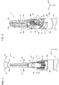
- Fig. 11 is a cross-sectional view illustrating the configuration of a medical treatment tool (Example 1).
- the medical treatment tool 204 includes a treatment tool unit 200, the shaft 212, a driving mechanism 215, and plural driving-side rods (driving-side elongated elements) 216.
- the driving mechanism 215 has the same configuration as the aforementioned driving mechanism 15.
- the driving mechanism 215 may have a different configuration from the driving mechanism 15 as long as the driving mechanism 215 is able to move the driving-side rods 216 in the longitudinal direction of the medical treatment tool 204.
- the driving-side rods 216 are rigid members accommodated in the shaft 212.
- the driving-side rods 216 include a first driving-side rod (a first elongated element) 216a and a second driving-side rod (a second elongated element) 216b.
- the medical treatment tool 204 includes three pairs of the first driving-side rod 216a and second driving-side rod 216b, for example.
- Fig. 11 illustrates the driving-side first and second rods 216a and 216b of one of the three pairs.
- the treatment tool unit 200 is configured to be attachable to an end section 212a of the shaft 212 on the opposite side to the driving mechanism 215. With such a configuration, the type of instrument is changed by detaching one treatment tool unit 200 from the shaft 212 and then attaching another treatment tool unit 200 to the shaft 212 without changing the entire medical treatment tool 204. This is economical because of no need to prepare plural entire medical treatment tools 204. In addition, there is also no need to prepare plural medical treatment tools 204 for replacement during surgery, thereby leading to provision of sufficient work space for surgery.
- the treatment tool unit 200 includes the distal end part 211, plural distal-side rods (rigid distal-side elongated elements) 213, a wire (a flexible elongated element) 214, an engaging section 221, and a cylindrical section 222.
- the distal end part 211 has the same configuration as the distal end part 11 according to the aforementioned configuration example.
- the distal end part 211 moves through the wire 214 being driven, since the wire 214 is fixed thereto.
- the configuration in which the distal end part 211 moves through the wire 214 being driven allows the distal end part 211 to move smoothly in a desired direction.
- the distal-side rods 213 are rigid members accommodated in the cylindrical section 222 and includes a first distal-side rod (a third elongated element) 213a and a second distal-side rod (a fourth elongated element) 213b.
- the first and second distal-side rods 213a and 213b connect to the wire 214.
- the wire 214 includes sufficient strength, flexibility, and durability.
- the treatment tool unit 200 includes three sets of the first distal-side rod 213a, second distal-side rod 213b, and wire 214, for example.
- Fig. 11 illustrates the first distal-side rod 213a, second distal-side rod 213b, and wire 214 of one of the three sets.
- the end section (opening) 222a of the cylindrical section 222 which is located on the side of the driving mechanism 215 when the treatment tool unit 200 is attached to the shaft 212 (hereinafter, just referred to as the driving mechanism 215 side), has the substantially same diameter as that of the end section 212a of the shaft 212.
- the engaging section 221 is substantially bar-shaped and is attached to near the end section 222a in the cylindrical section 222 through a joint section 223.
- the engaging section 221 protrudes from the end section 222a to the driving mechanism 215 side.
- the engaging section 221 is pivotable about the joint section 223 in the direction of arrow G1 or G2.
- the first end 221a of the engaging section 221 on the driving mechanism 215 side protrudes toward the central axis of the shaft 212.
- the engaging section 221 is energized by a not-illustrated spring, for example so that the first end 221a pivots in the direction of arrow G2, that is, toward the center axis of the shaft 212.
- the shaft 212 includes a cylindrical shape extended in the longitudinal direction of the medical treatment tool 204 in a similar manner to the shaft 12 according to the aforementioned configuration example.
- the shaft 212 is rotatable in the direction of arrow A.
- the shaft 212 accommodates the plural driving-side rods 216.
- a recess 224 which is engageable with the first end 221a of the engaging section 221 in the treatment tool unit 200, is formed.
- an operator presses a second end 221b of the engaging section 221 in the direction of arrow H.
- the first end 221a of the engaging section 221 pivots about the joint section 223 in the direction of arrow G1.
- the operator aligns the end section 222a of the cylindrical section 222 with the end section 212a of the shaft 212 and releases the pressure on the second end 221b in the direction of arrow H.
- the first end 221a then pivots about the joint section 223 in the direction of arrow G2 to engage with the recess 224.
- the treatment tool unit 200 is thus attached to the shaft 212.
- the operator presses the second end 221b in the direction of arrow H again to pivot the first end 221a in the direction of arrow G1.
- the first end 221a is thereby disengaged from the recess 224.
- the operator moves the treatment tool unit 200 away from the shaft 212, so that the treatment tool unit 200 is detached from the shaft 212.
- the plural distal-side rods 213 are engageable with the respective driving-side rods 216.
- each of the distal-side rods 213 includes a thick section (a first end) 231, which is an end on the distal end part 211 side, and a pin (a second end) 232, which is an end on the driving mechanism 215 side.
- the driving-side rod 216 includes a connector 234, which is an end on the distal end part 211 side and accommodates the pin 232.
- a passage section 233 is formed in the cylindrical section 222.
- the passage section 233 accommodates the thick section 231 inside and limits movement of the thick section 231 along the Z-axis.
- the passage section 233 is formed so that the distal-side rod 213 and wire 214 can be inserted therethrough. Both ends of the passage section 233 have diameters small enough to prohibit the thick section 231 from passing through the same.
- the distal-side rod 213 moves in the direction of arrow Z2, and the thick section 231 comes into contact with the end of the passage section 233 on the distal end part 211 side. This limits movement of the distal-side rod 213 in the direction of arrow Z2.
- the pin 232 is accommodated in the connector 234, so that the distal-side rod 213 and driving-side rod 216 engage with one another.
- the thick section 231 and pin 232 of the distal-side rod 213 and the passage section 233 of the cylindrical section 222 function as a releasing mechanism to disengage the distal-side rods 213 from the driving-side rods 216.
- the distal-side rod 213 thereby moves in the direction of arrow Z1.
- the thick section 231 of the distal-side rod 213 comes into contact with the end of the passage section 233 on the driving mechanism 151 side. This limits the movement of the distal-side rod 213 in the direction of arrow Z1.
- the operator further moves the treatment tool unit 200 away from the shaft 212.
- the pin 232 is then separated from the connector 234, so that the distal-side rod 213 is disengaged from the driving-side rod 216.
- the distal end part 211 is not limited to the configuration in which the distal end part 211 is integrated with the treatment tool unit 200 and may be configured as a different body from the treatment tool unit 200.
- the diameter of the end section 222a of the cylindrical section 222 may be larger than the diameter of the other part of the cylindrical section 222, that is, part thereof other than the end section 222a.
- the mechanism to engage the distal-side rod 213 and driving-side rod 216 is not limited to the configuration including the pin 232 and connector 234 as long as the mechanism includes sufficient strength and durability.
- the end of the distal-side rod 213 on the driving mechanism 215 side may be made of an elastic member.
- LAN Local Area Network
- the end of the distal-side rod 213 on the driving mechanism 215 side deforms while being accommodated in a connector which is the end of the driving-side rod 216 on the distal end part 211 side.
- the end of the distal-side rod 213 accommodated in the connector returns to the initial form within the connector and engages with a recess formed in the connector, for example.
- the treatment tool unit 200 may be configured so as to separate into plural members.
- the cylindrical section 222 is configured so as to separate into a member on the distal end part 211 side and a member on the driving mechanism 215 side
- the distal-side rod 213, which is accommodated in the cylindrical section 222 is also configured so as to separate into a member on the distal end part 211 side and a member on the driving mechanism 215 side.
- the treatment tool unit 200 thereby separates into two members.
- the distal end part 211 is not limited to the configuration in which the distal end part 211 connects to the wire 214 and may directly connect to the distal-side rod 213. In such a configuration, no work is necessary to adjust the tension of the wire 214 during the assembly process of the medical treatment tool 204 and the like. It is therefore possible to further facilitate assembly of the medical treatment tool 204 and the like.
- Fig. 12 is a cross-sectional view illustrating the configuration of a Medical treatment tool (Example 2).
- arrow Y1 indicates the positive direction of the Y axis while arrow Y2 indicates the negative direction of the Y axis.
- the cylindrical section 222 of the treatment tool unit 200 includes two first extensions 241a and 241b, which extend toward a driving mechanism 215.
- the two first extensions 241a and 241b are arranged next to each other in the direction perpendicular to the Y-Z plane.
- Fig. 12 illustrates only the first extension 241a and does not illustrate the first extension 241b.
- the shaft 212 includes two second extensions 242a and 242b, which extend from the end section 212a to the distal end part 211 side.
- the two second extensions 242a and 242b are arranged next to each other in the direction parallel to the Y-Z plane.
- the first extensions 241a and 241b of the treatment tool unit 200 connect to the second extensions 242a and 242b of the shaft 212 to form the outer circumference of the shaft 212.
- Each of the first extensions 241a and 241b includes: a recess 243 formed in a part of the connection with the second extension 242a; and a recess 244 formed in a part of the connection with the second extension 242b.
- the second extension 242a includes a protrusion 245, which is engageable with the recess 243
- the second extension 242b includes a protrusion 246, which is engageable with the recess 244.
- the operator moves the treatment tool unit 200 in the direction perpendicular to the Y-Z plane so that the protrusion 245 engages with the recess 243 while the protrusion 246 engages with the recess 244.
- the treatment tool unit 200 is thus attached to the shaft 212.
- the operator moves the treatment tool unit 200 in the direction perpendicular to the Y-Z plane.
- the protrusions 245 and 246 are disengaged from the recesses 243 and 244, respectively, so that the treatment tool unit 200 is detached from the shaft 212.
- the treatment tool unit 200 includes three sets of the first distal-side rod 213a, second distal-side rod 213b, and wire 214.
- the three first distal-side rods 213a included in the respective three sets are arranged next to each other in the direction perpendicular to the Y-Z plane.
- the three second distal-side rods 213b included in the respective three sets are also arranged next to each other in the direction perpendicular to the Y-Z plane.
- the first and second distal-side rods 213a and 213b connect to the wire 214.
- An end section 217 of the first distal-side rod 213a on the wire 214 side and an end section 218 of the second distal-side rod 213b on the wire 214 side are both tapered.
- Each of the first and second distal-side rods 213a and 213b includes a first engagement section 251, which is provided at an end thereof on the driving mechanism 215 side.
- the first engagement section 251 of the first distal-side rod 213a protrudes in the direction of arrow Y2, for example.
- the first engagement section 251 of the second distal-side rod 213b protrudes in the direction of arrow Y1, for example.
- the medical treatment tool 204 includes three sets of the driving-side first and second rods 216a and 216b.
- the three first driving-side rods 216a included in the respective three sets are arranged next to each other in the direction perpendicular to the Y-Z plane.
- the three second driving-side rods 216b included in the respective three sets are also arranged next to each other in the direction perpendicular to the Y-Z plane.
- Each of the driving-side first and second rods 216a and 216b includes a second engagement section 252, which is provided at an end on the distal end part 211 side when the treatment tool unit 200 is attached to the shaft 212 (hereinafter, just referred to as a distal end part 211 side).
- the second engagement section 252 of the first driving-side rod 216a protrudes in the direction of arrow Y1, for example.
- the second engagement section 252 of the second driving-side rod 216b protrudes in the direction of arrow Y2, for example.
- the second engagement sections 252 engage with the respective first engagement sections 251.
- the distal-side rods 213 and respective driving-side rods 216 thus engage with one another.
- the first and second engagement sections 251 and 252 function as a releasing mechanism to disengage the distal-side rods 213 from the driving-side rods 216.
- the first engagement sections 251 are disengaged from the second engagement sections 252, so that the distal-side rods 213 are thereby disengaged from the respective driving-side rods 216.
- the treatment tool unit 200 unnecessarily includes the wire 214.
- the distal end part 211 directly connects to the first and second distal-side rods 213a and 213b and moves through the first and second distal-side rods 213a and 213b being driven.
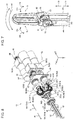
- Fig. 13 is a perspective view illustrating the configuration of a medical treatment tool (Example 3).
- the shaft 212 includes a fitting section 261, which extends from the end section 212a toward the distal end part 211.
- the fitting section 261 is cylindrical, and the outer diameter thereof is slightly smaller than the inner diameter of the end section 222a of the cylindrical section 222 of the treatment tool unit 200.
- the treatment tool unit 200 is thereby attached to the shaft 212 by bringing the treatment tool unit 200 close to the shaft 212 and fitting the fitting section 261 into the end section 222a.
- the operator moves the treatment tool unit 200 away from the shaft 212 to detach the treatment tool unit 200 from the shaft 212.
- the treatment tool unit 200 includes three sets of the first distal-side rod 213a, second distal-side rod 213b, and wire 214 in a similar manner to Example 2 described above.
- the three first distal-side rods 213a included in the respective three sets are arranged next to each other in the direction perpendicular to the Y-Z plane.
- the three second distal-side rods 213b included in the respective three sets are also arranged next to each other in the direction perpendicular to the Y-Z plane.
- the first and second distal-side rods 213a and 213b connect to the wire 214.
- the end section 217 of the first distal-side rod 213a on the wire 214 side and the end section 218 of the second distal-side rod 213b on the wire 214 side are both tapered.
- Each of the first and second distal-side rods 213a and 213b includes the first engagement section 251, which is provided at the end thereof on the driving mechanism 215 side.
- the first engagement section 251 of the first distal-side rod 213a protrudes in the direction of arrow Y2, for example.
- the first engagement section 251 of the second distal-side rod 213b protrudes in the direction of arrow Y1, for example.
- the three first distal-side rods 213a are fixed to a pressing section 271, which constitutes a part of the outer circumference of the cylindrical section 222.
- the pressing section 271 is energized in the direction of arrow Y2 by a not-illustrated spring, for example.
- the three second distal-side rods 213b are fixed to a pressing section 272, which constitutes a part of the outer circumference of the cylindrical section 222.
- the pressing section 272 is energized in the direction of arrow Y1 by a not-illustrated spring, for example.
- the medical treatment tool 204 includes three sets of the first and second driving-side rods 216a and 216b.
- the three first driving-side rods 216a included in the respective three sets are arranged next to each other in the direction perpendicular to the Y-Z plane.
- the three second driving-side rods 216b included in the respective three sets are also arranged next to each other in the direction perpendicular to the Y-Z plane.
- Each of the first and second driving-side rods 216a and 216b includes a second engagement section 252, which is provided at an end on the distal end part 211 side.
- the second engagement section 252 of the first driving-side rod 216a protrudes in the direction of arrow Y1, for example.
- the second engagement section 252 of the second driving-side rod 216b protrudes in the direction of arrow Y2, for example.
- the first engagement section 251 of the first distal-side rods 213a is tapered. As the cylindrical section 222 moves in the direction of arrow Z1, therefore, the two first engagement sections 251 properly move close to each other along the Y axis and finally engage with the second engagement sections 252.
- the operator presses the pressing section 271 in the direction of arrow Y1 and presses the pressing section 272 in the direction of arrow Y2.
- the first engagement section 251 of the first distal-side rod 213a thereby moves in the direction of arrow Y1 while the first engagement section 251 of the second distal-side rod 213b moves in the direction of arrow Y2.
- the operator brings the treatment tool unit 200 close to the shaft 212 so that the first engagement sections 251 overlap the second engagement sections 252 on the Y-axis.
- the operator stops pressing the pressing sections 271 and 272, the first engagement sections 251 engage with the respective second engagement sections 252.
- the distal-side rods 213 thus engage with the respective driving-side rods 216.
- the first engagement sections 251, second engagement sections 252, and pressing sections 271 and 272 function as a releasing mechanism to disengage the distal-side rods 213 from the driving-side rods 216.
- the first engagement sections 251 are disengaged from the second engagement sections 252.
- the distal-side rods 213 are disengaged from the driving-side rods 216.
- the treatment tool unit 200 unnecessarily includes the wire 214.
- the distal end part 211 directly connects to the first and second distal-side rods 213a and 213b and moves through the first and second distal-side rods 213a and 213b being driven.
Abstract
Description
- The invention relates to a drive unit for operating distal end parts, such as grasping forceps used in surgeries, a medical treatment tool, and a surgical system.
- In the endoscopic surgery field, surgery assistant robots have been heretofore employed in some cases. A surgery assistant robot includes a patient-side apparatus provided with manipulators, for example. Suitable medical treatment tools are attached to the manipulators and are remotely operated for surgery. As an example of such a medical treatment tool, Patent Literature 1 (Specification of
US Patent No. 6394998 ) discloses a medical treatment tool that uses plural spools as a driving mechanism to wind or unwind flexible elongated elements such as wire for moving the distal end parts, such as grasping forceps. - Patent Literature 1: Specification of
US Patent No. 6394998 - However, such a surgery assistant robot requires complicated work to assemble medical treatment tools, such as winding flexible members extending from a distal end part to the driving mechanism, around spools, and adjusting the tension of the flexible members while fixing the spools with screws or the like.
- The invention was made to solve the aforementioned problem. An object thereof is to provide a drive unit that facilitates assembly of a medical treatment tool, the medical treatment tool, and a surgical system.
- A drive unit according to an aspect of the invention to achieve the aforementioned object is a drive unit for driving elongated elements to operate a distal end part of a medical treatment tool, the drive unit including: a first gear that rotates about a first axis; a second gear that rotates about a second axis extending in a direction perpendicular to the first axis; and a third gear that rotates about a third axis extending in a direction perpendicular to the first axis. The elongated elements include: a first elongated element that is rigid and meshes with the second gear; and a second elongated element that is rigid and meshes with the third gear, and the second and third gears mesh with the first gear. The distal end part is operated in such a manner that as the first gear rotates, the first elongated element moves in a longitudinal direction of the medical treatment tool while the second elongated element moves in a direction opposite to the direction in which the first elongated element moves.
- A medical treatment tool according to an aspect of the invention to achieve the aforementioned object includes: the drive unit; the distal end part that is operated by the first and second elongated elements; and a shaft that accommodates the first and second elongated elements.
- A medical treatment tool according to another aspect of the invention to achieve the aforementioned object includes: a driving mechanism that includes three of the drive units; the distal end part that is controlled with three pairs of the first and second elongated elements; and a shaft that accommodates the three pairs of the first and second elongated elements.
- A surgical system according to an aspect of the invention to achieve the aforementioned object includes: the medical treatment tool; and a manipulator including the transmitter member that engages with the receiver member.
- According to the invention, it is possible to further facilitate assembly of a medical treatment tool.
-
-
Fig. 1 is a view illustrating a configuration of a surgical system; -
Fig. 2 is a view illustrating a configuration of a medical treatment tool; -
Fig. 3 is a perspective view illustrating a configuration of a distal end part of the medical treatment tool illustrated inFig. 2 ; -
Fig. 4 is a side view illustrating the configuration of the distal end part of the medical treatment tool illustrated inFig. 3 ; -
Fig. 5 is a view illustrating a configuration of a combination of rods and a wire, as an example of an elongated element used in the medical treatment tool; -
Fig. 6 is a view illustrating an arrangement example of wound wires; -
Fig. 7 is a view illustrating a configuration of a distal end part in a modification of a medical treatment tool; -
Fig. 8 is a perspective view illustrating a configuration of a driving mechanism and a driving device; -
Fig. 9 is a front view illustrating the configuration of the driving mechanism illustrated inFig. 8 ; -
Fig. 10 is a perspective view illustrating a configuration example of a transmission section; -
Fig. 11 is a cross-sectional view illustrating a configuration of a medical treatment tool (Example 1); -
Fig. 12 is a cross-sectional view illustrating a configuration of a medical treatment tool (Example 2); and -
Fig. 13 is a perspective view illustrating a configuration of a medical treatment tool (Example 3). -
Fig. 1 is a view illustrating a configuration of a surgical system. - With reference to
Fig. 1 , asurgical system 300 is, for example, a system in which a surgeon Q uses a patient-side apparatus 1 to perform an endoscopic surgery for a subject P, including a human or an animal. Thesurgical system 300 includes the patient-side apparatus 1 and anoperation apparatus 2 for operating the patient-side apparatus 1. - The surgeon Q inputs a movement instruction for the patient-side apparatus 1 into the
operation apparatus 2, and theoperation apparatus 2 transmits an instruction signal including the inputted movement instruction, to the patient-side apparatus 1. The patient-side apparatus 1 receives the instruction signal transmitted from theoperation apparatus 2 and operates anendoscopic assembly 4a and amedical treatment tool 4b, which are connected to distal ends of the patient-side apparatus 1, based on the movement instruction included in the received instruction signal. - To be more specific, the
operation apparatus 2 includes anoperation input section 5, which includes anoperation manipulator 5a and anoperation pedal 5b, and amonitor 5c. Themonitor 5c displays images captured by theendoscopic assembly 4a. Theoperation manipulator 5a andoperation pedal 5b are equipment for the surgeon Q to input a movement instruction. - The surgeon Q inputs a movement instruction to the
operation apparatus 2 by operating theoperation manipulator 5a andoperation pedal 5b while watching the diseased area in the image displayed on themonitor 5c. Theoperation apparatus 2 transmits an instruction signal including the inputted movement instruction, to the patient-side apparatus 1 via wire or wirelessly. - The patient-side apparatus 1 includes: a
positioner 7; a platform 8, which is attached to the top end of thepositioner 7;manipulators 3, which are detachably attached to the platform 8; theendoscopic assembly 4a; themedical treatment tool 4b; and acontroller 6 that controls movement of the patient-side apparatus 1. - The
endoscopic assembly 4a andmedical treatment tool 4b are attached to therespective manipulators 3. Themedical treatment tool 4b is grasper forceps (a grasper), a needle driver, scissors, or the like. - The
controller 6 receives an instruction signal from theoperation apparatus 2 and operates theendoscopic assembly 4a andmedical treatment tool 4b based on the received instruction signal. - Specifically, the
controller 6 receives an instruction signal and based on a movement instruction included in the instruction signal, first controls thepositioner 7 for positioning of the platform 8. Thecontroller 6 also positions themanipulators 3 so that theendoscopic assembly 4a andmedical treatment tool 4b are located at predetermined initial positions relative to a not-illustrated cannula placed on the body surface of the subject P. - Based on the movement instruction, the
controller 6 then outputs a control signal to drive theendoscopic assembly 4a ormedical treatment tool 4b, to theendoscopic assembly 4a ormedical treatment tool 4b via themanipulators 3. Theendoscopic assembly 4a andmedical treatment tool 4b then operate in accordance with the control signals received from thecontroller 6. -
Fig. 2 is a view illustrating the configuration of the medical treatment tool. - With reference to
Fig. 2 , themedical treatment tool 4b includes adistal end part 11, ashaft 12,elongated elements 13 to operate thedistal end part 11, and adriving mechanism 15 to drive theelongated elements 13. Thedriving mechanism 15 is activated by adriving device 16 including a driving source. Thedriving device 16 is a part of thecorresponding manipulator 3 and is provided at the distal end of themanipulator 3, for example. - In this specification, the term "elongated elements" collectively means rods, wires, cables, or the like. Rigid ones, such as rods, are referred to as rigid elongated elements while flexible ones, such as wire and cable, are referred to as flexible elongated elements. In order to describe elongated elements without distinguishing rigid and flexible ones, the elongated elements, including rigid and flexible ones, are collectively referred to as elongated elements.
- The
distal end part 11 includes twojaws jaws shaft 12 includes a cylindrical shape extending in the longitudinal direction of themedical treatment tool 4b and is rotatable in the direction of arrow A. Theshaft 12 is thus rotatable about the axis along the longitudinal direction thereof. - As the
elongated elements 13, rods, for example, are rigid members accommodated in theshaft 12. As theelongated elements 13, wires, for example, are flexible members which are made of tungsten, stainless, or the like and have sufficient strength, flexibility, and durability. - The
driving mechanism 15 detachably connects to thecorresponding manipulator 3 in the patient-side apparatus 1 illustrated inFig. 1 . Thedriving mechanism 15 receives a control signal from the patient-side apparatus 1 via themanipulator 3 and moves theelongated elements 13 in the longitudinal direction of themedical treatment tool 4b in accordance with the control signal. The detailed configuration of thedriving mechanism 15 is described later. -
Fig. 3 is a perspective view illustrating the configuration of the distal end part of the medical treatment tool illustrated inFig. 2 . - With reference to
Fig. 3 , thedistal end part 11 includes awrist section 23, in addition to thejaws wrist section 23 is attached to anend section 12a of theshaft 12 through ajoint section 31. Thewrist section 23 is pivotable about thejoint section 31 in the direction of arrow B. - The
jaws wrist section 23 through ajoint section 32. Thejaws finger sections pulley sections finger sections joint section 32 in the direction of arrow C.The pulley sections joint section 32. - The direction that the
joint section 31 extends is preferably different from the direction that thejoint section 32 extends. Herein, it is assumed that the direction that thejoint section 31 extends is at 90 degrees to the direction that thejoint section 32 extends. Hereinafter, the direction that thejoint section 31 extends is the direction of Y axis; the direction that thejoint section 32 extends is the direction of X axis; and the longitudinal direction of theshaft 12 is the direction of Z axis. -
Fig. 4 is a side view illustrating the configuration of the distal end part of the medical treatment tool illustrated inFig. 3 . - With reference to
Fig. 4 , free ends 21a and 22a of thejaws joint section 32 as indicated by arrows C1 and C2, respectively. The free ends 21a and 22a thereby move close to and away from each other or pivot in the same direction. - The
distal end part 11 further includes afirst pulley section 41, asecond pulley section 42, athird pulley section 43, afourth pulley section 44, and afifth pulley section 45, in addition to thejaws wrist section 23. Each of the first tofourth pulley sections 41 to 44 includes an inner pulley and an outer pulley. - The first, second, and
fifth pulley sections end section 12a through thejoint section 31 and are rotatable about thejoint section 31. Thethird pulley section 43 is attached to thewrist section 23 through ajoint section 33 and is rotatable about thejoint section 33. Thefourth pulley section 44 is attached to thewrist section 23 through ajoint section 34 and is rotatable about thejoint section 34. - The planes of rotation of the
first pulley section 41 andthird pulley section 43 lie in the substantially same plane. The planes of rotation of thesecond pulley section 42 andfourth pulley section 44 lie in the substantially same plane. -
Fig. 5 is a view illustrating the configuration of a combination of rods and a wire as an example of the elongated element used in the medical treatment tool. - With reference to
Fig. 5 , eachelongated element 13 includes a first rod (a first rigid elongated element) 13a, a second rod (a second rigid elongated element) 13b, and awire 14. The first andsecond rods wire 14. Thewire 14 is provided with athick section 14a near the center thereof. - Herein, the first and
second rods same wire 14. However, thewire 14 connected to thefirst rod 13a may be a different member from thewire 14 connected to thesecond rod 13b. - The first and
second rods toothed sections wire 14. Thetoothed sections driving mechanism 15. - The
medical treatment tool 4b illustrated inFig. 2 includes three sets of thefirst rod 13a,second rod 13b, andwire 14, for example. Hereinafter, the threefirst rods 13a included in the three sets are referred to asfirst rods second rods 13b included in the three sets are referred to assecond rods wires 14 included in the three sets are referred to aswires - The
wire 141 connects the first andsecond rods wire 142 connects the first andsecond rods wire 143 connects the first andsecond rods -
Fig. 6 is a view illustrating an example of wound wires. InFig. 6 , arrow Z1 indicates the positive direction of the Z axis while arrow Z2 indicates the negative direction of the Z axis. - With reference to
Fig. 6 , in the assembly process of themedical treatment tool 4b, thewire 141 is wound around the outer pulley of thefirst pulley section 41 and the outer pulley of thethird pulley section 43, then wound around thepulley section 25b of thejaw 22, and then wound around the inner pulley of thefourth pulley section 44 and the inner pulley of thesecond pulley section 42. - The
thick section 14a of thewire 141 illustrated inFig. 5 is fitted to a not-illustrated recess formed in thefinger section 24b of thejaw 22 illustrated inFig. 6 , for example. Thewire 141 is thereby fixed to thejaw 22, so that thejaw 22 moves through thewire 141 being driven. - The
wire 142 is wound around the inner pulley of thefirst pulley section 41 and the inner pulley of thethird pulley section 43, wound around thepulley section 25a of thejaw 22, and then wound around the outer pulley of thefourth pulley section 44 and the outer pulley of thesecond pulley section 42. - The
thick section 14a of thewire 142 illustrated inFig. 5 is fitted to a not-illustrated recess formed in thefinger section 24a of thejaw 21 illustrated inFig. 6 , for example. Thewire 142 is thereby fixed to thejaw 21, so that thejaw 21 moves through thewire 142 being driven. - The
wire 143 is wound around thefifth pulley section 45. Thethick section 14a of thewire 143 illustrated inFig. 5 is fitted to a not-illustrated recess formed in thewrist section 23 illustrated inFig. 6 , for example. Thewire 143 is thereby fixed to thewrist section 23, so that thewrist section 23 moves through thewire 143 being driven. - In such a manner, the
jaws wrist section 23 of thedistal end part 11 move through thewires distal end part 11 operates smoothly in a desired direction. - When the
first rod 131a is pulled in the direction of arrow Z1, thejaw 22 pivots about thejoint section 32 in the direction of arrow C2a. In other words, thejaw 22 pivots towards thejaw 21 in the circumferential direction of a circle centered at thejoint section 32. When thesecond rod 131b is pulled in the direction of arrow Z1, thejaw 22 pivots about thejoint section 32 in the direction of arrow C2b. In other words, thejaw 22 pivots away from thejaw 21 in the circumferential direction of a circle centered at thejoint section 32. - When the
first rod 132a is pulled in the direction of arrow Z1, thejaw 21 pivots about thejoint section 32 in the direction of arrow C1a. In other words, thejaw 21 pivots away from thejaw 22 in the circumferential direction of a circle centered at thejoint section 32. When thesecond rod 132b is pulled in the direction of arrow Z1, thejaw 21 pivots about thejoint section 32 in the direction of arrow C1b. In other words, thejaw 21 pivots toward thejaw 22 in the circumferential direction of a circle centered at thejoint section 32. - When the
second rod 131b andfirst rod 132a are pulled in the direction of arrow Z1 simultaneously, thejaws joint section 32. When thefirst rod 131a andsecond rod 132b are pulled in the direction of arrow Z1 simultaneously, thejaws joint section 32. - When the
first rods jaws joint section 32, as indicated by arrow D1. In other words, thejaw 21 pivots in the direction of arrow C1a while thejaw 22 pivots in the direction of arrow C2a. - When the
second rods jaws joint section 32, as indicated by arrow D2. In other words, thejaw 21 pivots in the direction of arrow C1b while thejaw 22 pivots in the direction of arrow C2b. - When the
first rod 133a is pulled in the direction of arrow Z1, thewrist section 23, which is illustrated inFigs. 3 and 4 , pivots about thejoint section 31 in the direction of arrow B2. In other words, thewrist section 23 pivots counterclockwise in the circumferential direction of a circle centered at thejoint section 31, as seen along the Y axis from the negative side toward the positive side. When thesecond rod 133b is pulled in the direction of arrow Z1, thewrist section 23 pivots about thejoint section 31 in the direction of arrow B1. In other words, thewrist section 23 pivots clockwise in the circumferential direction of a circle centered at thejoint section 31, as seen along the Y axis from the negative side toward the positive side. - In such a manner, the
jaw 21,jaw 22, andwrist section 23, which are fixed to thewires first rods second rods - The
distal end part 11 of themedical treatment tool 4b is not limited to the configuration in which thedistal end part 11 is operated by theelongated elements 13 each including a combination of rods and wire and may have a configuration in which thedistal end part 11 is operated by elongated elements each including only rods. -
Fig. 7 is a view illustrating the configuration of a distal end part of a modification of a medical treatment tool. - With reference to
Fig. 7 , thedistal end part 11 includes twojaws gears jaws gears end section 12a of theshaft 12 illustrated inFig. 3 , through ajoint section 73. Thegears joint section 73, and thejaws joint section 73 in the direction of arrow D1 or D2. - The
medical treatment tool 4b includes first rods (first rigid elongated elements) 91a and 92a and second rods (second rigid elongated elements) 91b and 92b instead of the rods and wires. - The first and
second rods gear 81. As the first andsecond rods gear 81 rotates about thejoint section 73. Thejaw 71 thereby pivots about thejoint section 73 together with thegear 81. - The first and
second rods gear 82. As the first andsecond rods gear 82 rotates about thejoint section 73. Thejaw 72 thereby pivots about thejoint section 73 together with thegear 82. - Specifically, when the
first rod 91a is pulled in the direction of arrow Z1, thesecond rod 91b moves in the direction of arrow Z2, and thegear 81 rotates in the direction of arrow E1. Thejaw 71 thereby pivots in the direction of arrow C1a. When thefirst rod 91a is pulled in the direction of arrow Z2, thesecond rod 91b moves in the direction of arrow Z1, and thegear 81 rotates in the direction of arrow E2. Thejaw 71 thereby pivots in the direction of arrow C1b. - When the
first rod 92a is pulled in the direction of arrow Z1, thesecond rod 92b moves in the direction of arrow Z2, and thegear 82 rotates in the direction of arrow F1. Thejaw 72 thereby pivots in the direction of arrow C2a. When thefirst rod 92a is pulled in the direction of arrow Z2, thesecond rod 92b moves in the direction of arrow Z1, and thegear 82 rotates in the direction of arrow F2. Thejaw 72 thereby pivots in the direction of arrow C2b. - When the
first rods second rods distal end part 11 in such a manner, no work is necessary to adjust wire tension during the assembly process of themedical treatment tool 4b or other processes. It is therefore possible to further facilitate assembly of themedical treatment tool 4b and the like. -
Fig. 8 is a perspective view illustrating the configurations of the driving mechanism and driving device.Fig. 9 is a front view illustrating the configuration of the driving mechanism illustrated inFig. 8. Figs. 8 and9 do not illustrate a housing that covers thedriving mechanism 15 for explanation of thedriving mechanism 15. - With reference to
Fig. 8 , thedriving mechanism 15 includes plural drive units 101. Each drive unit 101 includes afirst gear 61; a second gear 62, which meshes with thefirst rod 13a; a third gear 63, which meshes with thesecond rod 13b; and a receiver member as a part of atransmission section 75 to rotate thefirst gear 61. Thetransmission section 75 is described in detail later. - The driving
device 16 includes plural actuators 50. Each actuator 50 receives a control signal from the patient-side apparatus 1 illustrated inFig. 1 , through themanipulator 3 and rotates the corresponding receiver member of thetransmission section 75 in accordance with the control signal. The receiver member rotates itself to rotate the correspondingfirst gear 61. - To be more specific, with reference to
Fig. 9 , the second and third gears 62 and 63 have substantially the same shape. Thefirst gear 61 rotates about a first axis 161 parallel to the longitudinal direction of themedical treatment tool 4b. The second gear 62 rotates about a second axis 162, which extends perpendicularly to the first axis 161. The third gear 63 rotates about a third axis 163, which extends perpendicularly to the first axis 161. - The
first gear 61 is a substantially-conical bevel gear, for example. Thefirst gear 61 includes teeth in the conical surface. Each of the second and third gears 62 and 63 is a gear including a combination of a substantially-conical bevel gear and a cylindrical gear, for example. In the second and third gears 62 and 63, teeth are formed in the lateral surface of the conical part, and teeth are formed in the side surface of the cylindrical part. - The second and third gears 62 and 63 mesh with the
first gear 61. To be more specific, the teeth in the lateral surface of the second gear 62 and the teeth in the lateral surface of the third gear 63 mesh with the teeth in thefirst gear 61. - As the
first gear 61 rotates, the second and third gears 62 and 63 rotate in the same direction as seen from thefirst gear 61 side. Specifically, when the second gear 62 rotates clockwise as seen from thefirst gear 61 side, the third gear 63 also rotates clockwise as seen from thefirst gear 61. - In the aforementioned example, the first, second, and
third gears 61, 62, and 63 are all bevel gears. However, thefirst gear 61 may be a crown gear while the second and third gears 62 and 63 are spur gears. Such a configuration also implements the same rotary movement as described above. - The teeth formed in the side surface of the cylindrical part of the second gear 62 mesh with the
toothed section 20a formed in thefirst rod 131a illustrated inFig. 5 . The second gear 62 andfirst rod 131a constitute a rack-and-pinion structure. Thefirst rod 131a moves in the longitudinal direction of theshaft 12 as the second gear 62 rotates. - The teeth formed in the side surface of the cylindrical part of the third gear 63 mesh with the
toothed section 20b, which is formed in thesecond rod 131b illustrated inFig. 5 . The third gear 63 andsecond rod 131b constitute a rack-and-pinion structure. Thesecond rod 131b moves in the longitudinal direction of theshaft 12 as the third gear 63 rotates. - The first and
second rods shaft 12. To be more specific, thefirst rod 131a andsecond rod 131b are positioned so that the position of engagement of thefirst rod 131a in the side surface of the disk of the second gear 62 as seen from thefirst gear 61 is opposite to the position of engagement of thesecond rod 131b in the side surface of the disk of the third gear 63 as seen from thefirst gear 61. Specifically, the second gear 62 meshes with thefirst rod 131a on the right side as seen from thefirst gear 61 while the third gear 63 meshes with thesecond rod 131b on the left side as seen from thefirst gear 61. - The first and
second rods shaft 12 as thefirst gear 61 rotates. - Such a configuration that the
distal end part 11 is operated by using the first andsecond rods first gear 61 rotates eliminates the need for work to wind thewire 14 around thedriving mechanism 15 and adjust the tension thereof. It is therefore possible to further facilitate assembly of themedical treatment tool 4b. In addition, in the configuration using the first andsecond rods - The
driving mechanism 15 includes three drive units 101, each including the aforementioned first, second, andthird gears 61, 62, and 63, for example. Hereinafter, the three drive units 101 are referred to as drive units 101A, 101B, and 101C. The drive units 101 A, 101B, and 101C are positioned at substantially equal intervals in the circumferential direction of theshaft 12. The rotational axes of thefirst gears 61 of the drive units 101 are positioned at substantially equal intervals in particular. - The first, second, and
third gears 61, 62, and 63 included in the drive unit 101A are referred to as first, second, and third gears 61A, 62A, and 63A, respectively. The first, second, andthird gears 61, 62, and 63 included in the drive unit 101B are referred to as first, second, and third gears 61B, 62B, and 63B, respectively. The first, second, andthird gears 61, 62, and 63 included in the drive unit 101C are referred to as first, second, and third gears 61C, 62C, and 63C, respectively. - In the drive unit 101A, the second and third gears 62A and 63A mesh with the first gear 61A. The second gear 62A meshes with the
first rod 131a to operate thejaw 22 while the third gear 63A meshes with thesecond rod 131b to operate thejaw 22. - In the drive unit 101B, the second and third gears 62B and 63B mesh with the first gear 61B. The second gear 62B meshes with the
first rod 132a to operate thejaw 21 while the third gear 63B meshes with thesecond rod 132b to control thejaw 21. - In the drive unit 101C, the second and third gears 62C and 63C mesh with the first gear 61C. The second gear 62C meshes with the
first rod 133a to operate thewrist section 23 while the third gear 63C meshes with thesecond rod 133b to operate thewrist section 23. - With reference to
Fig. 8 again, the drivingdevice 16 includes four actuators 51, 52, 53, and 54 as the plural actuators 50, for example. The actuators 51, 52, 53, and 54 are servo motors, for example. - The driving
device 16 further includes afourth gear 64, afifth gear 65, arotation mechanism 76, and atransmitter member 78 as a part of thetransmission section 75. Thefourth gear 64 rotates the first gear 61C through thetransmission section 75. Thefifth gear 65 meshes with thefourth gear 64. - The actuator 51 rotates the first gear 61A through the
transmission section 75 in accordance with a control signal from the patient-side apparatus 1 (illustrated inFig. 1 ). The actuator 52 rotates the first gear 61B through thetransmission section 75 in accordance with a control signal from the patient-side apparatus 1 in a similar manner to the actuator 51. - The actuator 53 rotates the
fifth gear 65 in accordance with a control signal from the patient-side apparatus 1. As thefifth gear 65 rotates, thefourth gear 64 rotates to rotate the first gear 61C through thetransmission section 75. - The actuator (a rotation mechanism driving actuator) 54 rotates a
sixth gear 66, which constitutes therotation mechanism 76, in accordance with a control signal from the patient-side apparatus 1. As thesixth gear 66 rotates, the wholemedical treatment tool 4b rotates about an axis parallel to the longitudinal axis (a shaft axis) of theshaft 12. - Specifically, the
rotation mechanism 76 includes a fixed rotational axis adjustment gear (a sun gear, not illustrated) having a disk shape, in addition to thesixth gear 66. The side surface of the disk of the rotational axis adjustment gear meshes with thesixth gear 66. The central axis of the rotational axis adjustment gear coincides with the shaft axis. Thesixth gear 66 rotates about its own axis while revolving around the rotational axis adjustment gear (functioning as a planet gear), so that thedistal end part 11 of themedical treatment tool 4b rotates about the shaft axis. - The aforementioned configuration that the actuator 54 rotates the
shaft 12 in the direction of arrow A allows the direction of thedistal end part 11 to change appropriately. - The
rotation mechanism 76 needs to have a configuration that allows themedical treatment tool 4b to rotate about an axis parallel to the longitudinal direction (the shaft axis) of theshaft 12. Therotation mechanism 76 unnecessarily employs such a planetary gear mechanism. -
Fig. 10 is a perspective view illustrating the configuration of the transmission section. - With reference to
Fig. 10 , thetransmission section 75 includes areceiver member 77 of thedriving mechanism 15; and atransmitter member 78 of the drivingdevice 16. - The
receiver member 77 connects to thefirst gear 61 through arotation section 111. Thereceiver member 77 engages with thetransmitter member 78 and rotates when thetransmitter member 78 rotates. Thetransmitter member 78 is rotationally driven directly or indirectly by the corresponding actuator 50 illustratedFig. 8 . - To be more specific, the
receiver member 77 includes arotatable disk section 201. In the main surface of thedisk section 201, an engagedsection 202 is formed. Thetransmitter member 78 includes an engagingsection 221, which is engageable with the engagedsection 202 of thereceiver member 77. - The engaged
section 202 of thereceiver member 77 is a groove or a recess, for example. In the main surface of thedisk section 201, the engagedsection 202 has a continuous pattern which is not symmetric about any line through the center of the main surface. The engagingsection 221 of thetransmitter member 78 is a protrusion, for example. In the main surface of the transmitter member 220, the engagingsection 221 has a continuous pattern which is not symmetric about any line through the center of the main surface, similarly to the engagedsection 202. - With such a configuration, the direction of the
receiver member 77 to drive thedistal end part 11 illustrated inFig. 2 is determined uniquely among 360 degrees. - The patterns of the engaging
section 221 and engagedsection 202 are linear, for example. In addition, the pattern of the engagingsection 221 passes through the center of the main surface of thetransmitter member 78 while the pattern of the engagedsection 202 passes through the center of the main surface of thedisk section 201. - The engaging
section 221 is tapered so as to gradually decrease in width toward thereceiver member 77 in the direction of the Z axis, which is perpendicular to the main surface of thetransmitter member 78, that is, in the negative direction of the Z axis illustrated inFig. 10 . - The
transmitter member 78 is energized toward thereceiver member 77, that is, in the negative direction of the Z axis illustrated inFig. 10 , by a spring or the like. Some misalignment in the positional relationship between the engagedsection 202 and the engagingsection 221 is corrected during assembly thereof so that the engagingsection 221 fits into the engagedsection 202. This further facilitates the work to engage the engagingsection 221 and the engagedsection 202. - The engaging
section 221 may be a groove or a recess instead of a protrusion. When the engagingsection 221 is a groove or a recess, the engagedsection 202 is a protrusion which is engageable with the engagingsection 221. - The shape of the engaged
section 202 needs to be formed in a continuous pattern which is not symmetric about any line through the center of thedisk section 201 in the rotation surface of thedisk section 201. The shape of the engagedsection 202 is not limited to the aforementioned shape. - The
receiver member 77 does not need to directly engage with thetransmitter member 78. The movement of thetransmitter member 78 may be transmitted to thereceiver member 77 through an adaptor integrated with a drape. - With reference to
Fig. 8 again, the actuators 51, 52, and 53 rotate the first gears 61A, 61B, and 61C in accordance with a control signal, respectively, as described above. - When the first gear 61A rotates, the second and third gears 62A and 63A rotate, and the
first rod 131a, which meshes with the second gear 62A, and the second rod 121b, which meshes with the third gear 63A, move in opposing directions along the Z axis. When thefirst rod 131a orsecond rod 131b is pulled in the direction of arrow Z1, thus, thejaw 22 pivots in the direction of arrow C1a or C1b illustrated inFig. 6 . - Specifically, when the first gear 61A rotates in the direction of arrow K11 illustrated in
Fig. 8 , the second gear 62A rotates in the direction of arrow K12, and thefirst rod 131a, which meshes with the second gear 62A, moves in the direction of arrow Z2. In this case, the third gear 63A rotates in the direction of arrow K13, and thesecond rod 131b, which connects to the third gear 63A, moves in the direction of arrow Z1. - When the
first rod 131a moves in the direction of arrow Z2 while thesecond rod 131b moves in the direction of arrow Z1 in such a manner, thejaw 22 pivots in the direction of arrow C2b as illustrated inFig. 6 . - When the first gear 61A rotates in the direction of arrow K21, the second gear 62A rotates in the direction of arrow K22, and the
first rod 131a, which connects to the second gear 62A, moves in the direction of arrow Z1. In this case, the third gear 63A rotates in the direction of arrow K23, and thesecond rod 131b, which connects to the third gear 63A, moves in the direction of arrow Z2. - When the
first rod 131a moves in the direction of arrow Z1 while thesecond rod 131b moves in the direction of arrow Z2 in such a manner, thejaw 22 pivots in the direction of arrow C2a as illustrated inFig. 6 . - In the case where the first gear 61B rotates, similarly to the case where the first gear 61A rotates, the second and third gears 62B and 63B rotate with the rotating first gear 61B, and the
first rod 132a, which meshes with the second gear 62B, and thesecond rod 132b, which meshes with the third gear 63B, move in opposing directions along the Z axis. Thejaw 21 thereby pivots in the direction of arrow C2a or C2b as illustrated inFig. 6 . - In the case where the first gear 61C rotates, similarly to the cases where the first and second gears 61A and 61B rotate, the second and third gears 62C and 63C rotate with the rotating first gear 61C, and the
first rod 133a, which meshes with the second gear 62C, and thesecond rod 133b, which meshes with the third gear 63C, move in opposing directions along the Z axis. Thewrist section 23 thereby pivots in the direction of arrow B1 or B2 as illustrated inFig. 3 . - The
driving mechanism 15 is not limited to the configuration including the three drive units 101. For example, when two pairs of two rods that move in opposing directions along the Z axis as illustrated inFig. 7 , thedriving mechanism 15 includes two drive units 101 corresponding to the two pairs of rods. - When the
driving mechanism 15 includes the three drive units 101, three members of thedistal end part 11, including thejaw 21,jaw 22, andwrist section 23, are driven independently. This allows for fine manipulation during surgery. Thedriving mechanism 15 therefore preferably includes the three drive units 101. - Next, a description is given of other configuration examples of the invention with reference to the drawings. The same or equivalent portions in the drawings are given the same reference numerals, and the description thereof is not repeated.
- In the description of the above configuration example, the
shaft 12, which is provided for themedical treatment tool 4b, is a single unit connecting thedistal end part 11 and drivingmechanism 15. - In that case, the
distal end part 11 cannot be detached from theshaft 12. In order to replace thedistal end part 11, it is therefore necessary to change the entiremedical treatment tool 4b. However, the structure to connect themedical treatment tool 4b and an arm section 10 is comparatively complicated, thus the work to replace themedical treatment tool 4b is not easy. - On the other hand, a
medical treatment tool 204 according to this configuration example is configured so that members of a distal end part 211 can be detached from ashaft 212 and attached to the same. The distal end part 211 can thereby be replaced without changing the entiremedical treatment tool 204. Hereinafter, the configuration of themedical treatment tool 204 according to this configuration example is described. -
Fig. 11 is a cross-sectional view illustrating the configuration of a medical treatment tool (Example 1). - With reference to
Fig. 11 , themedical treatment tool 204 includes atreatment tool unit 200, theshaft 212, a driving mechanism 215, and plural driving-side rods (driving-side elongated elements) 216. - The driving mechanism 215 has the same configuration as the
aforementioned driving mechanism 15. The driving mechanism 215 may have a different configuration from thedriving mechanism 15 as long as the driving mechanism 215 is able to move the driving-side rods 216 in the longitudinal direction of themedical treatment tool 204. - The driving-side rods 216 are rigid members accommodated in the
shaft 212. The driving-side rods 216 include a first driving-side rod (a first elongated element) 216a and a second driving-side rod (a second elongated element) 216b. - The
medical treatment tool 204 includes three pairs of the first driving-side rod 216a and second driving-side rod 216b, for example.Fig. 11 illustrates the driving-side first andsecond rods - The
treatment tool unit 200 is configured to be attachable to anend section 212a of theshaft 212 on the opposite side to the driving mechanism 215. With such a configuration, the type of instrument is changed by detaching onetreatment tool unit 200 from theshaft 212 and then attaching anothertreatment tool unit 200 to theshaft 212 without changing the entiremedical treatment tool 204. This is economical because of no need to prepare plural entiremedical treatment tools 204. In addition, there is also no need to prepare pluralmedical treatment tools 204 for replacement during surgery, thereby leading to provision of sufficient work space for surgery. - To be more specific, the
treatment tool unit 200 includes the distal end part 211, plural distal-side rods (rigid distal-side elongated elements) 213, a wire (a flexible elongated element) 214, an engagingsection 221, and acylindrical section 222. - As described above, the distal end part 211 has the same configuration as the
distal end part 11 according to the aforementioned configuration example. The distal end part 211 moves through thewire 214 being driven, since thewire 214 is fixed thereto. - In such a manner, the configuration in which the distal end part 211 moves through the
wire 214 being driven allows the distal end part 211 to move smoothly in a desired direction. - The distal-side rods 213 are rigid members accommodated in the
cylindrical section 222 and includes a first distal-side rod (a third elongated element) 213a and a second distal-side rod (a fourth elongated element) 213b. The first and second distal-side rods wire 214. Thewire 214 includes sufficient strength, flexibility, and durability. - The
treatment tool unit 200 includes three sets of the first distal-side rod 213a, second distal-side rod 213b, andwire 214, for example.Fig. 11 illustrates the first distal-side rod 213a, second distal-side rod 213b, andwire 214 of one of the three sets. - The end section (opening) 222a of the
cylindrical section 222, which is located on the side of the driving mechanism 215 when thetreatment tool unit 200 is attached to the shaft 212 (hereinafter, just referred to as the driving mechanism 215 side), has the substantially same diameter as that of theend section 212a of theshaft 212. - The engaging
section 221 is substantially bar-shaped and is attached to near theend section 222a in thecylindrical section 222 through ajoint section 223. The engagingsection 221 protrudes from theend section 222a to the driving mechanism 215 side. The engagingsection 221 is pivotable about thejoint section 223 in the direction of arrow G1 or G2. - The first end 221a of the engaging
section 221 on the driving mechanism 215 side protrudes toward the central axis of theshaft 212. The engagingsection 221 is energized by a not-illustrated spring, for example so that the first end 221a pivots in the direction of arrow G2, that is, toward the center axis of theshaft 212. - The
shaft 212 includes a cylindrical shape extended in the longitudinal direction of themedical treatment tool 204 in a similar manner to theshaft 12 according to the aforementioned configuration example. Theshaft 212 is rotatable in the direction of arrow A. Theshaft 212 accommodates the plural driving-side rods 216. In theend section 212a of theshaft 212, arecess 224, which is engageable with the first end 221a of the engagingsection 221 in thetreatment tool unit 200, is formed. - To attach the
treatment tool unit 200 to theshaft 212, an operator presses a second end 221b of the engagingsection 221 in the direction of arrow H. The first end 221a of the engagingsection 221 pivots about thejoint section 223 in the direction of arrow G1. - In the state where the first end 221a is pivoted in the direction of arrow G1, the operator aligns the
end section 222a of thecylindrical section 222 with theend section 212a of theshaft 212 and releases the pressure on the second end 221b in the direction of arrow H. The first end 221a then pivots about thejoint section 223 in the direction of arrow G2 to engage with therecess 224. Thetreatment tool unit 200 is thus attached to theshaft 212. - To detach the
treatment tool unit 200 from theshaft 212, the operator presses the second end 221b in the direction of arrow H again to pivot the first end 221a in the direction of arrow G1. The first end 221a is thereby disengaged from therecess 224. The operator moves thetreatment tool unit 200 away from theshaft 212, so that thetreatment tool unit 200 is detached from theshaft 212. - The plural distal-side rods 213 are engageable with the respective driving-side rods 216.
- To be more specific, each of the distal-side rods 213 includes a thick section (a first end) 231, which is an end on the distal end part 211 side, and a pin (a second end) 232, which is an end on the driving mechanism 215 side. The driving-side rod 216 includes a
connector 234, which is an end on the distal end part 211 side and accommodates thepin 232. - In the
cylindrical section 222, apassage section 233 is formed. Thepassage section 233 accommodates thethick section 231 inside and limits movement of thethick section 231 along the Z-axis. Thepassage section 233 is formed so that the distal-side rod 213 andwire 214 can be inserted therethrough. Both ends of thepassage section 233 have diameters small enough to prohibit thethick section 231 from passing through the same. - As described above, when the operator brings the
treatment tool unit 200 close to theshaft 212 while pressing the second end 221b of the engagingsection 221 in the direction of arrow H to pivot the first end 221a in the direction of arrow G1, thepin 232 comes into contact with theconnector 234 and receives force from theconnector 234 in the direction of arrow Z2. - The distal-side rod 213 moves in the direction of arrow Z2, and the
thick section 231 comes into contact with the end of thepassage section 233 on the distal end part 211 side. This limits movement of the distal-side rod 213 in the direction of arrow Z2. In this state, when the operator further moves thetreatment tool unit 200 close to theshaft 212, thepin 232 is accommodated in theconnector 234, so that the distal-side rod 213 and driving-side rod 216 engage with one another. - In the case where the operator detaches the
treatment tool unit 200 from theshaft 212, thethick section 231 and pin 232 of the distal-side rod 213 and thepassage section 233 of thecylindrical section 222 function as a releasing mechanism to disengage the distal-side rods 213 from the driving-side rods 216. - Specifically, when the operator moves the
treatment tool unit 200 away from theshaft 212 while pressing the first end 221a in the direction of arrow H, thepin 232, which is in theconnector 234, is pulled in the direction of arrow Z1. - The distal-side rod 213 thereby moves in the direction of arrow Z1. The
thick section 231 of the distal-side rod 213 comes into contact with the end of thepassage section 233 on the driving mechanism 151 side. This limits the movement of the distal-side rod 213 in the direction of arrow Z1. In this state, the operator further moves thetreatment tool unit 200 away from theshaft 212. Thepin 232 is then separated from theconnector 234, so that the distal-side rod 213 is disengaged from the driving-side rod 216. - That configuration in which the end of the distal-side rod 213 on the driving mechanism 215 side is the
pin 232 while the end of the driving-side rod 216 on the distal end part 211 side is theconnector 234 allows for easy engagement and disengagement of the distal-side rod 213 and driving-side rod 216. - The distal end part 211 is not limited to the configuration in which the distal end part 211 is integrated with the
treatment tool unit 200 and may be configured as a different body from thetreatment tool unit 200. - The diameter of the
end section 222a of thecylindrical section 222 may be larger than the diameter of the other part of thecylindrical section 222, that is, part thereof other than theend section 222a. Such a configuration prevents the components for engagement of the distal-side rod 213 and driving-side rod 216, including thepin 232 andconnector 234, from being excessively miniaturized, thus facilitating manufacturing the components and ensuring strength of engagement. - The mechanism to engage the distal-side rod 213 and driving-side rod 216 is not limited to the configuration including the
pin 232 andconnector 234 as long as the mechanism includes sufficient strength and durability. - The end of the distal-side rod 213 on the driving mechanism 215 side may be made of an elastic member. In such an end of LAN (Local Area Network) cable, when pressurized in a predetermined direction, the end of the distal-side rod 213 on the driving mechanism 215 side deforms while being accommodated in a connector which is the end of the driving-side rod 216 on the distal end part 211 side. In this case, when the position of the distal-side rod 213 relative to the driving-side rod 216 reaches the predetermined position, the end of the distal-side rod 213 accommodated in the connector returns to the initial form within the connector and engages with a recess formed in the connector, for example.
- The
treatment tool unit 200 may be configured so as to separate into plural members. For example, thecylindrical section 222 is configured so as to separate into a member on the distal end part 211 side and a member on the driving mechanism 215 side, and the distal-side rod 213, which is accommodated in thecylindrical section 222, is also configured so as to separate into a member on the distal end part 211 side and a member on the driving mechanism 215 side. Thetreatment tool unit 200 thereby separates into two members. - The distal end part 211 is not limited to the configuration in which the distal end part 211 connects to the
wire 214 and may directly connect to the distal-side rod 213. In such a configuration, no work is necessary to adjust the tension of thewire 214 during the assembly process of themedical treatment tool 204 and the like. It is therefore possible to further facilitate assembly of themedical treatment tool 204 and the like. -
Fig. 12 is a cross-sectional view illustrating the configuration of a Medical treatment tool (Example 2). InFig. 12 , arrow Y1 indicates the positive direction of the Y axis while arrow Y2 indicates the negative direction of the Y axis. - With reference to
Fig. 12 , thecylindrical section 222 of thetreatment tool unit 200 includes twofirst extensions 241a and 241b, which extend toward a driving mechanism 215. The twofirst extensions 241a and 241b are arranged next to each other in the direction perpendicular to the Y-Z plane.Fig. 12 illustrates only thefirst extension 241a and does not illustrate the first extension 241b. - The
shaft 212 includes twosecond extensions end section 212a to the distal end part 211 side. The twosecond extensions - The
first extensions 241a and 241b of thetreatment tool unit 200 connect to thesecond extensions shaft 212 to form the outer circumference of theshaft 212. - Each of the
first extensions 241a and 241b includes: arecess 243 formed in a part of the connection with thesecond extension 242a; and arecess 244 formed in a part of the connection with thesecond extension 242b. Thesecond extension 242a includes aprotrusion 245, which is engageable with therecess 243, and thesecond extension 242b includes aprotrusion 246, which is engageable with therecess 244. - To attach the
treatment tool unit 200 to theshaft 212, the operator moves thetreatment tool unit 200 in the direction perpendicular to the Y-Z plane so that theprotrusion 245 engages with therecess 243 while theprotrusion 246 engages with therecess 244. Thetreatment tool unit 200 is thus attached to theshaft 212. - To detach the
treatment tool unit 200 from theshaft 212, the operator moves thetreatment tool unit 200 in the direction perpendicular to the Y-Z plane. Theprotrusions recesses treatment tool unit 200 is detached from theshaft 212. - The
treatment tool unit 200 includes three sets of the first distal-side rod 213a, second distal-side rod 213b, andwire 214. The three first distal-side rods 213a included in the respective three sets are arranged next to each other in the direction perpendicular to the Y-Z plane. The three second distal-side rods 213b included in the respective three sets are also arranged next to each other in the direction perpendicular to the Y-Z plane. - The first and second distal-
side rods wire 214. Anend section 217 of the first distal-side rod 213a on thewire 214 side and anend section 218 of the second distal-side rod 213b on thewire 214 side are both tapered. - In such a configuration, even when the driven
wire 214 comes into contact with the end section of the distal-side rod 213 connecting to anotherwire 214, thewire 214 is prevented from being damaged by the angular end of the anotherwire 214. - Each of the first and second distal-
side rods first engagement section 251, which is provided at an end thereof on the driving mechanism 215 side. Thefirst engagement section 251 of the first distal-side rod 213a protrudes in the direction of arrow Y2, for example. Thefirst engagement section 251 of the second distal-side rod 213b protrudes in the direction of arrow Y1, for example. - The
medical treatment tool 204 includes three sets of the driving-side first andsecond rods side rods 216a included in the respective three sets are arranged next to each other in the direction perpendicular to the Y-Z plane. The three second driving-side rods 216b included in the respective three sets are also arranged next to each other in the direction perpendicular to the Y-Z plane. - Each of the driving-side first and
second rods second engagement section 252, which is provided at an end on the distal end part 211 side when thetreatment tool unit 200 is attached to the shaft 212 (hereinafter, just referred to as a distal end part 211 side). Thesecond engagement section 252 of the first driving-side rod 216a protrudes in the direction of arrow Y1, for example. Thesecond engagement section 252 of the second driving-side rod 216b protrudes in the direction of arrow Y2, for example. - As described above, when the operator moves the
treatment tool unit 200 in the direction perpendicular to the Y-Z plane to attach thetreatment tool unit 200 to theshaft 212, thesecond engagement sections 252 engage with the respectivefirst engagement sections 251. The distal-side rods 213 and respective driving-side rods 216 thus engage with one another. - In the process where the operator detaches the
treatment tool unit 200 from theshaft 212, the first andsecond engagement sections - Specifically, when the operator moves the
treatment tool unit 200 in the direction perpendicular to the Y-Z plane to detach thetreatment tool unit 200 from theshaft 212, thefirst engagement sections 251 are disengaged from thesecond engagement sections 252, so that the distal-side rods 213 are thereby disengaged from the respective driving-side rods 216. - The
treatment tool unit 200 unnecessarily includes thewire 214. In such a case, the distal end part 211 directly connects to the first and second distal-side rods side rods -
Fig. 13 is a perspective view illustrating the configuration of a medical treatment tool (Example 3). - With reference to
Fig. 13 , theshaft 212 includes afitting section 261, which extends from theend section 212a toward the distal end part 211. Thefitting section 261 is cylindrical, and the outer diameter thereof is slightly smaller than the inner diameter of theend section 222a of thecylindrical section 222 of thetreatment tool unit 200. Thetreatment tool unit 200 is thereby attached to theshaft 212 by bringing thetreatment tool unit 200 close to theshaft 212 and fitting thefitting section 261 into theend section 222a. - To detach the
treatment tool unit 200 from theshaft 212, the operator moves thetreatment tool unit 200 away from theshaft 212 to detach thetreatment tool unit 200 from theshaft 212. - The
treatment tool unit 200 includes three sets of the first distal-side rod 213a, second distal-side rod 213b, andwire 214 in a similar manner to Example 2 described above. The three first distal-side rods 213a included in the respective three sets are arranged next to each other in the direction perpendicular to the Y-Z plane. The three second distal-side rods 213b included in the respective three sets are also arranged next to each other in the direction perpendicular to the Y-Z plane. - The first and second distal-
side rods wire 214. Theend section 217 of the first distal-side rod 213a on thewire 214 side and theend section 218 of the second distal-side rod 213b on thewire 214 side are both tapered. - Each of the first and second distal-
side rods first engagement section 251, which is provided at the end thereof on the driving mechanism 215 side. Thefirst engagement section 251 of the first distal-side rod 213a protrudes in the direction of arrow Y2, for example. Thefirst engagement section 251 of the second distal-side rod 213b protrudes in the direction of arrow Y1, for example. - The three first distal-
side rods 213a are fixed to apressing section 271, which constitutes a part of the outer circumference of thecylindrical section 222. Thepressing section 271 is energized in the direction of arrow Y2 by a not-illustrated spring, for example. - The three second distal-
side rods 213b are fixed to apressing section 272, which constitutes a part of the outer circumference of thecylindrical section 222. Thepressing section 272 is energized in the direction of arrow Y1 by a not-illustrated spring, for example. - The
medical treatment tool 204 includes three sets of the first and second driving-side rods side rods 216a included in the respective three sets are arranged next to each other in the direction perpendicular to the Y-Z plane. The three second driving-side rods 216b included in the respective three sets are also arranged next to each other in the direction perpendicular to the Y-Z plane. - Each of the first and second driving-
side rods second engagement section 252, which is provided at an end on the distal end part 211 side. Thesecond engagement section 252 of the first driving-side rod 216a protrudes in the direction of arrow Y1, for example. Thesecond engagement section 252 of the second driving-side rod 216b protrudes in the direction of arrow Y2, for example. - To attach the
treatment tool unit 200 to theshaft 212, the operator just needs to simply insert thecylindrical section 222 into thefitting section 261. Thefirst engagement section 251 of the first distal-side rods 213a is tapered. As thecylindrical section 222 moves in the direction of arrow Z1, therefore, the twofirst engagement sections 251 properly move close to each other along the Y axis and finally engage with thesecond engagement sections 252. - To attach the
treatment tool unit 200 to theshaft 212 more reliably, the operator presses thepressing section 271 in the direction of arrow Y1 and presses thepressing section 272 in the direction of arrow Y2. Thefirst engagement section 251 of the first distal-side rod 213a thereby moves in the direction of arrow Y1 while thefirst engagement section 251 of the second distal-side rod 213b moves in the direction of arrow Y2. - In this state, the operator brings the
treatment tool unit 200 close to theshaft 212 so that thefirst engagement sections 251 overlap thesecond engagement sections 252 on the Y-axis. The operator then stops pressing thepressing sections first engagement sections 251 engage with the respectivesecond engagement sections 252. The distal-side rods 213 thus engage with the respective driving-side rods 216. - In the case where the operator detaches the
treatment tool unit 200 from theshaft 212, thefirst engagement sections 251,second engagement sections 252, andpressing sections - Specifically, when the operator presses the
pressing section 271 in the direction of arrow Y1 and presses thepressing section 272 in the direction of arrow Y2 to detach thetreatment tool unit 200 from theshaft 212, thefirst engagement sections 251 are disengaged from thesecond engagement sections 252. When the operator moves thetreatment tool unit 200 away from theshaft 212 in this state, the distal-side rods 213 are disengaged from the driving-side rods 216. - The
treatment tool unit 200 unnecessarily includes thewire 214. In this case, the distal end part 211 directly connects to the first and second distal-side rods side rods - The other configurations and movements are the same as those of the aforementioned configuration examples, and the detailed description thereof is not repeated.
- The characteristics of the aforementioned
treatment tool unit 200 and themedical treatment tool 204 andsurgical system 300 including the same are summarized as follows. - [1] A treatment tool unit, which is attachable to a shaft that accommodates rigid driving-side elongated elements to operate the distal end part of a medical treatment tool, the treatment tool unit including:
- a cylindrical section including an opening having the substantially same diameter as that of an end of the shaft on the tip-section side; and
- rigid distal-side elongated elements accommodated in the cylindrical section, in which the distal-side elongated elements include a first end located on the tip-section side and a second end which is engageable with an end of the corresponding one of the driving-side elongated elements on the driving-section side.
- [2] The treatment tool unit according to [1], in which the second end is a pin, and
the end of the driving-side elongated element on the tip-section side is a connector to accommodate the pin. - [3] The treatment tool unit according to [1] or [2] in which the distal-side elongated element includes a thick section, and the cylindrical section includes a passage section that limits a range of movement of the thick section.
- [4] The treatment tool unit according to any one of [1] to [3], the cylindrical section includes an engagement section that is engageable with the shaft
- [5] The treatment tool unit according to any one of [1] to [4)] further including a releasing mechanism to disengage the driving-side elongated element from the distal-side elongated element.
- [6] The treatment tool unit according to [5], in which the releasing mechanism is provided for the cylindrical section, and the releasing mechanism is pressed toward the inside of the cylindrical section to release the engagement.
- [7] The treatment tool unit according to any one of [1] to [6], further including the distal end part that is operated directly or indirectly by the distal-side elongated element being driven.
- [8] The treatment tool unit according to [7], in which the distal-side elongated element connects to a flexible elongated element, and
the distal end part is operated through movement of the flexible elongated element. - [9] The treatment tool unit according to [8], in which an end of the distal-side elongated element on the flexible elongated element's side is tapered.
- [10] The treatment tool unit according to any one of [1] to [9], in which the diameter of the opening is greater than the diameter of the other part of the cylindrical section than the opening.
- [11] A medical treatment tool, including: the treatment tool unit according to any one of [7] to [10]; the distal end part; the shaft; and a drive unit to drive the distal end part.
- [12] The medical treatment tool according to [11], in which the drive unit includes:
- a first gear that rotates about a first axis;
- a second gear that rotates about a second axis extending in a direction perpendicular to the first axis; and
- a third gear that rotates about a third axis extending in the direction perpendicular to the first axis, and
- the driving-side elongated elements include:
- a first elongated element that meshes with the second gear; and
- a second elongated element that meshes with the third gear, and
- the second and third gears mesh with the first gear, and
- the distal end part is operated in such a manner that as the first gear rotates, the first elongated element moves in a longitudinal direction of the medical treatment tool while the second elongated element moves in a direction opposite to the direction in which the first elongated element moves.
- [13] The medical treatment tool according to [12], in which the first, second, and third gears are bevel gears.
- [14] The medical treatment tool according to [12] or [13], in which the first gear connects to a receiver member which is engageable with a transmitter member that is driven by an actuator.
- [15] The medical treatment tool according to any one of [11] to [14], further comprising a driving mechanism including three of the drive units.
- [16] A surgical system, including: the medical treatment tool according to [14] or [15] referring to [14]; and a manipulator including the transmitter member that engages with the receiver member.
- The above-described embodiments should be considered to be illustrative in all respects and not restrictive. The scope of the invention is indicated by the appended claims, rather than by foregoing description, and is intended to include all alterations within the meaning and range equivalent to the claims.
-
- 3 MANIPULATOR
- 4b MEDICAL TREATMENT TOOL
- 11 DISTAL END PART
- 12 SHAFT
- 13 ROD (RIGID ELONGATED ELEMENT)
- 13a, 131a, 132a, 133a FIRST ROD (FIRST RIGID ELONGATED ELEMENT)
- 13b, 131b, 132b, 133b SECOND ROD (SECOND RIGID ELONGATED ELEMENT)
- 14, 141, 142, 143 WIRE (FLEXIBLE ELONGATED ELEMENT)
- 15 DRIVING MECHANISM
- 50, 51, 52, 53, 54 ACTUATOR (ROTATION MECHANISM)
- 61, 61A, 61B, 61C FIRST GEAR
- 62, 62A, 62B, 62C SECOND GEAR
- 63, 63A, 63B, 63C THIRD GEAR
- 77 RECEIVER MEMBER
- 78 TRANSMITTER MEMBER
- 101 DRIVE UNIT
- 161 FIRST AXIS
- 162 SECOND AXIS
- 163 THIRD AXIS
- 200 TREATMENT TOOL UNIT
- 300 SURGICAL SYSTEM
Claims (15)
- A drive unit for driving elongated elements to operate a distal end part of a medical treatment tool, the drive unit comprising:a first gear that rotates about a first axis;a second gear that rotates about a second axis extending in a direction perpendicular to the first axis; anda third gear that rotates about a third axis extending in a direction perpendicular to the first axis, whereinthe elongated elements include:a first elongated element that is rigid and meshes with the second gear; anda second elongated element that is rigid and meshes with the third gear,the second and third gears mesh with the first gear, andthe distal end part is operated in such a manner that as the first gear rotates, the first elongated element moves in a longitudinal direction of the medical treatment tool while the second elongated element moves in a direction opposite to the direction in which the first elongated element moves.
- The drive unit according to claim 1, wherein
a position where the first elongated element is engaged with a side surface of a disk of the second gear as seen from the first gear is opposite to a position where the second elongated element is engaged with a side surface of a disk of the third gear as seen from the first gear. - The drive unit according to claim 1 or 2, wherein
the first, second, and third gears are bevel gears. - The drive unit according to claim 1 or 2, wherein
the first gear is a crown gear, and the second and third gears are spur gears. - The drive unit according to any one of claims 1 to 4, wherein
the first and second elongated elements individually connect to a flexible elongated element, and
the distal end part is operated in response to movements of the flexible elongated element. - The drive unit according to any one of claims 1 to 5, wherein
the first gear connects to a receiver member which is engageable with a transmitter member that is driven by an actuator. - A medical treatment tool, comprising:the drive unit according to any one of claims 1 to 6;the distal end part that is operated by the first and second elongated elements; anda shaft that accommodates the first and second elongated elements.
- The medical treatment tool according to claim 7, wherein
the distal end part is detachable from the shaft. - The medical treatment tool according to claim 7 or 8, further comprising:a third elongated element that is rigid and is engageable with the first elongated element; anda fourth elongated element that is rigid and is engageable with the second elongated element.
- A medical treatment tool, comprising:a driving mechanism that includes three of the drive units according to any one of claims 1 to 6;the distal end part that is operated with three pairs of the first and second elongated elements; anda shaft that accommodates the three pairs of the first and second elongated elements.
- The medical treatment tool according to claim 10, wherein
the first axes of the three drive units are positioned at equal intervals. - A surgical system, comprising:the medical treatment tool according to any one of claims 7 to 11 referring to claim 6; anda manipulator including the transmitter member that engages with the receiver member.
- The surgical system according to claim 12, wherein
the manipulator includes a rotation mechanism that rotates the shaft. - The surgical system according to claim 13, wherein
the rotation mechanism includes:a rotational axis adjustment gear fixed such that a central axis of the rotational axis adjustment gear coincides with a rotational axis of the shaft; anda gear that rotates about an axis thereof while revolving around the rotational axis adjustment gear. - The surgical system according to claim 13 or 14, wherein
the manipulator further includes:three of the actuators that drive three of the transmitter members; anda rotation mechanism driving actuator that drives the rotation mechanism.
Applications Claiming Priority (2)
| Application Number | Priority Date | Filing Date | Title |
|---|---|---|---|
| JP2017091233 | 2017-05-01 | ||
| PCT/JP2018/002555 WO2018203425A1 (en) | 2017-05-01 | 2018-01-26 | Drive unit, surgical instrument for medical use, and operation system |
Publications (2)
| Publication Number | Publication Date |
|---|---|
| EP3620122A1 true EP3620122A1 (en) | 2020-03-11 |
| EP3620122A4 EP3620122A4 (en) | 2020-05-13 |
Family
ID=64016595
Family Applications (1)
| Application Number | Title | Priority Date | Filing Date |
|---|---|---|---|
| EP18795246.0A Withdrawn EP3620122A4 (en) | 2017-05-01 | 2018-01-26 | Drive unit, surgical instrument for medical use, and operation system |
Country Status (4)
| Country | Link |
|---|---|
| US (2) | US20190216557A1 (en) |
| EP (1) | EP3620122A4 (en) |
| JP (2) | JP6836649B2 (en) |
| WO (2) | WO2018203426A1 (en) |
Cited By (1)
| Publication number | Priority date | Publication date | Assignee | Title |
|---|---|---|---|---|
| CN112690902A (en) * | 2021-03-25 | 2021-04-23 | 成都博恩思医学机器人有限公司 | Electric hook structure |
Families Citing this family (4)
| Publication number | Priority date | Publication date | Assignee | Title |
|---|---|---|---|---|
| JP6741731B2 (en) * | 2018-08-28 | 2020-08-19 | 株式会社メディカロイド | Robot surgical instrument and assembling method thereof |
| US11331814B2 (en) * | 2018-09-13 | 2022-05-17 | Kinova Inc. | Articulated mechanism with protective sleeve at joint |
| JP2023103866A (en) * | 2022-01-14 | 2023-07-27 | キヤノン株式会社 | medical system |
| WO2023163572A1 (en) * | 2022-02-28 | 2023-08-31 | 주식회사 리브스메드 | Surgical instrument and surgical robot comprising same |
Family Cites Families (17)
| Publication number | Priority date | Publication date | Assignee | Title |
|---|---|---|---|---|
| US6394998B1 (en) | 1999-01-22 | 2002-05-28 | Intuitive Surgical, Inc. | Surgical tools for use in minimally invasive telesurgical applications |
| JP4287354B2 (en) * | 2004-10-25 | 2009-07-01 | 株式会社日立製作所 | Surgical instruments |
| US7862553B2 (en) * | 2005-07-13 | 2011-01-04 | Microline Surgical, Inc. | Tip and shaft connection for medical device |
| KR101477738B1 (en) * | 2006-06-13 | 2014-12-31 | 인튜어티브 서지컬 인코포레이티드 | Minimally invasive surgical system |
| JP4654165B2 (en) * | 2006-08-08 | 2011-03-16 | テルモ株式会社 | Working mechanism and manipulator |
| US9096033B2 (en) * | 2007-06-13 | 2015-08-04 | Intuitive Surgical Operations, Inc. | Surgical system instrument sterile adapter |
| US8292889B2 (en) * | 2010-02-26 | 2012-10-23 | Tyco Healthcare Group Lp | Drive mechanism for articulation of a surgical instrument |
| JP5578560B2 (en) * | 2010-09-03 | 2014-08-27 | 株式会社ニデック | Anterior segment measurement device |
| JP5608486B2 (en) * | 2010-09-06 | 2014-10-15 | オリンパス株式会社 | Surgical power transmission adapter and medical manipulator system |
| JP5636239B2 (en) * | 2010-09-24 | 2014-12-03 | カール シュトルツ ゲゼルシャフト ミット ベシュレンクテル ハフツング ウント コンパニー コマンディートゲゼルシャフト | Medical manipulator |
| JP2014005785A (en) * | 2012-06-26 | 2014-01-16 | Unicarriers Corp | Exhaust device for vehicle |
| DE102012013242A1 (en) * | 2012-07-03 | 2014-01-09 | Kuka Laboratories Gmbh | Surgical instrument arrangement for manipulator surgery system, has modular motor drive unit which has drive arrangement with output element and instrument shaft which is detachably connected to drive unit |
| US11373768B2 (en) * | 2013-03-12 | 2022-06-28 | Bwxt Mpower, Inc. | Refueling water storage tank (RWST) with tailored passive emergency core cooling (ECC) flow |
| US9730718B2 (en) * | 2013-03-13 | 2017-08-15 | Boston Scientific Scimed, Inc. | Medical device with quick-release mechanism |
| WO2016025700A1 (en) * | 2014-08-15 | 2016-02-18 | Intuitive Surgical Operations, Inc. | Force transmission mechanism for surgical instrument, and related systems and methods |
| US10080579B2 (en) * | 2015-03-25 | 2018-09-25 | Medtronic Ps Medical, Inc. | Pin drive rotary surgical cutting tools and powered handpieces |
| WO2017043128A1 (en) * | 2015-09-11 | 2017-03-16 | オリンパス株式会社 | Medical treatment instrument |
-
2018
- 2018-01-26 JP JP2019516358A patent/JP6836649B2/en active Active
- 2018-01-26 JP JP2019516359A patent/JP6813675B2/en active Active
- 2018-01-26 WO PCT/JP2018/002556 patent/WO2018203426A1/en active Application Filing
- 2018-01-26 WO PCT/JP2018/002555 patent/WO2018203425A1/en unknown
- 2018-01-26 EP EP18795246.0A patent/EP3620122A4/en not_active Withdrawn
-
2019
- 2019-03-27 US US16/365,692 patent/US20190216557A1/en not_active Abandoned
- 2019-10-31 US US16/670,896 patent/US20200060779A1/en not_active Abandoned
Cited By (1)
| Publication number | Priority date | Publication date | Assignee | Title |
|---|---|---|---|---|
| CN112690902A (en) * | 2021-03-25 | 2021-04-23 | 成都博恩思医学机器人有限公司 | Electric hook structure |
Also Published As
| Publication number | Publication date |
|---|---|
| US20190216557A1 (en) | 2019-07-18 |
| US20200060779A1 (en) | 2020-02-27 |
| JPWO2018203426A1 (en) | 2019-07-11 |
| EP3620122A4 (en) | 2020-05-13 |
| WO2018203426A1 (en) | 2018-11-08 |
| JP6836649B2 (en) | 2021-03-03 |
| JPWO2018203425A1 (en) | 2020-02-27 |
| WO2018203425A1 (en) | 2018-11-08 |
| JP6813675B2 (en) | 2021-01-13 |
Similar Documents
| Publication | Publication Date | Title |
|---|---|---|
| EP3620122A1 (en) | Drive unit, surgical instrument for medical use, and operation system | |
| US11198226B2 (en) | Surgical robot | |
| EP2996613B1 (en) | Articulated tool positioner and system employing same | |
| CN111888012B (en) | Surgical instrument platform | |
| US8974374B2 (en) | Surgical manipulator | |
| CN107708597B (en) | Robot for operation | |
| JP6081309B2 (en) | Medical manipulator | |
| CN111936027A (en) | Arm device | |
| EP3321047A1 (en) | Surgical robot | |
| CN106456256A (en) | Robotic surgical systems and instrument drive units | |
| JP2015535191A (en) | Self-conflict drive for medical devices | |
| JP2018187029A (en) | Medical treatment device and surgical system | |
| US11324560B2 (en) | Surgical instrument | |
| WO2018174227A1 (en) | Gripping mechanism | |
| EP3682835A1 (en) | Support device and surgical system | |
| JP6712646B2 (en) | Medical instruments and surgical systems | |
| US20200323598A1 (en) | Surgical instrument and surgical robot | |
| US11369442B2 (en) | Surgical system | |
| JP2020168532A (en) | Medical treatment tool | |
| JP4022534B2 (en) | Medical manipulator |
Legal Events
| Date | Code | Title | Description |
|---|---|---|---|
| STAA | Information on the status of an ep patent application or granted ep patent |
Free format text: STATUS: THE INTERNATIONAL PUBLICATION HAS BEEN MADE |
|
| PUAI | Public reference made under article 153(3) epc to a published international application that has entered the european phase |
Free format text: ORIGINAL CODE: 0009012 |
|
| STAA | Information on the status of an ep patent application or granted ep patent |
Free format text: STATUS: REQUEST FOR EXAMINATION WAS MADE |
|
| 17P | Request for examination filed |
Effective date: 20191127 |
|
| AK | Designated contracting states |
Kind code of ref document: A1 Designated state(s): AL AT BE BG CH CY CZ DE DK EE ES FI FR GB GR HR HU IE IS IT LI LT LU LV MC MK MT NL NO PL PT RO RS SE SI SK SM TR |
|
| AX | Request for extension of the european patent |
Extension state: BA ME |
|
| A4 | Supplementary search report drawn up and despatched |
Effective date: 20200409 |
|
| RIC1 | Information provided on ipc code assigned before grant |
Ipc: A61B 17/94 20060101ALI20200403BHEP Ipc: A61B 34/35 20160101ALI20200403BHEP Ipc: A61B 17/29 20060101AFI20200403BHEP Ipc: B25J 17/00 20060101ALI20200403BHEP |
|
| DAV | Request for validation of the european patent (deleted) | ||
| DAX | Request for extension of the european patent (deleted) | ||
| STAA | Information on the status of an ep patent application or granted ep patent |
Free format text: STATUS: THE APPLICATION HAS BEEN WITHDRAWN |
|
| 18W | Application withdrawn |
Effective date: 20210827 |