EP3620007B1 - Verfahren und vorrichtung zur interferenzmessung unter verwendung eines strahlverwaltungsreferenzsignals - Google Patents
Verfahren und vorrichtung zur interferenzmessung unter verwendung eines strahlverwaltungsreferenzsignals Download PDFInfo
- Publication number
- EP3620007B1 EP3620007B1 EP18793801.4A EP18793801A EP3620007B1 EP 3620007 B1 EP3620007 B1 EP 3620007B1 EP 18793801 A EP18793801 A EP 18793801A EP 3620007 B1 EP3620007 B1 EP 3620007B1
- Authority
- EP
- European Patent Office
- Prior art keywords
- ues
- cell
- interference
- beam management
- reference signals
- Prior art date
- Legal status (The legal status is an assumption and is not a legal conclusion. Google has not performed a legal analysis and makes no representation as to the accuracy of the status listed.)
- Active
Links
Images


Classifications
-
- H—ELECTRICITY
- H04—ELECTRIC COMMUNICATION TECHNIQUE
- H04B—TRANSMISSION
- H04B7/00—Radio transmission systems, i.e. using radiation field
- H04B7/02—Diversity systems; Multi-antenna system, i.e. transmission or reception using multiple antennas
- H04B7/04—Diversity systems; Multi-antenna system, i.e. transmission or reception using multiple antennas using two or more spaced independent antennas
- H04B7/0413—MIMO systems
- H04B7/0417—Feedback systems
-
- H—ELECTRICITY
- H04—ELECTRIC COMMUNICATION TECHNIQUE
- H04B—TRANSMISSION
- H04B7/00—Radio transmission systems, i.e. using radiation field
- H04B7/02—Diversity systems; Multi-antenna system, i.e. transmission or reception using multiple antennas
- H04B7/04—Diversity systems; Multi-antenna system, i.e. transmission or reception using multiple antennas using two or more spaced independent antennas
- H04B7/0413—MIMO systems
- H04B7/0452—Multi-user MIMO systems
-
- H—ELECTRICITY
- H04—ELECTRIC COMMUNICATION TECHNIQUE
- H04B—TRANSMISSION
- H04B17/00—Monitoring; Testing
- H04B17/30—Monitoring; Testing of propagation channels
- H04B17/309—Measuring or estimating channel quality parameters
- H04B17/345—Interference values
-
- H—ELECTRICITY
- H04—ELECTRIC COMMUNICATION TECHNIQUE
- H04B—TRANSMISSION
- H04B7/00—Radio transmission systems, i.e. using radiation field
- H04B7/02—Diversity systems; Multi-antenna system, i.e. transmission or reception using multiple antennas
- H04B7/04—Diversity systems; Multi-antenna system, i.e. transmission or reception using multiple antennas using two or more spaced independent antennas
- H04B7/06—Diversity systems; Multi-antenna system, i.e. transmission or reception using multiple antennas using two or more spaced independent antennas at the transmitting station
- H04B7/0613—Diversity systems; Multi-antenna system, i.e. transmission or reception using multiple antennas using two or more spaced independent antennas at the transmitting station using simultaneous transmission
- H04B7/0615—Diversity systems; Multi-antenna system, i.e. transmission or reception using multiple antennas using two or more spaced independent antennas at the transmitting station using simultaneous transmission of weighted versions of same signal
- H04B7/0619—Diversity systems; Multi-antenna system, i.e. transmission or reception using multiple antennas using two or more spaced independent antennas at the transmitting station using simultaneous transmission of weighted versions of same signal using feedback from receiving side
- H04B7/0621—Feedback content
- H04B7/0632—Channel quality parameters, e.g. channel quality indicator [CQI]
-
- H—ELECTRICITY
- H04—ELECTRIC COMMUNICATION TECHNIQUE
- H04J—MULTIPLEX COMMUNICATION
- H04J11/00—Orthogonal multiplex systems, e.g. using WALSH codes
- H04J11/0023—Interference mitigation or co-ordination
- H04J11/0026—Interference mitigation or co-ordination of multi-user interference
-
- H—ELECTRICITY
- H04—ELECTRIC COMMUNICATION TECHNIQUE
- H04W—WIRELESS COMMUNICATION NETWORKS
- H04W24/00—Supervisory, monitoring or testing arrangements
- H04W24/02—Arrangements for optimising operational condition
Definitions
- Embodiments of the present disclosure generally relate to the field of wireless communications, and particularly to a method and an apparatus for interference measurement using a beam management reference signal (BM-RS).
- BM-RS beam management reference signal
- Interference measurement resource needs to be allocated to perform interference measurement.
- the IMR transmission may be periodic, semi-persistent or aperiodic and the IMR may be based on a channel status information reference signal (CSI-RS), including a zero-power CSI-RS (ZP CSI-RS) and a non-zero power CSI-RS (NZP CSI-RS).
- CSI-RS channel status information reference signal
- ZP CSI-RS zero-power CSI-RS
- NZP CSI-RS non-zero power CSI-RS
- US 2014/198751 A1 describes a method implemented in a base station used in a wireless communications system that includes configuring multiple channel state information (CSI) processes for a user equipment (UE), and configuring, for the UE, a plurality of non-zero power (NZP) CSI reference signal (RS) resources, each of which is associated with an antenna array.
- CSI channel state information
- NZP non-zero power
- RS CSI reference signal
- NTT DOCOMO INC (RAPPORTEUR): "RAN WG's progress on NR technology SI in the October meeting", 3GPP DRAFT; R2-168015, 3RD GENERATION PARTNERSHIP, XP051177722 , discusses various aspects of New Radio communication protocols ZTE ET AL: "Discussion on Measurements and RS Design for CLIMitigation", 3GPP DRAFT; R1-1701615 - 8.1.6.2 DISCUSSION ON MEASUREMENT AND RS DESIGN FOR CLI, 3RD GENERATION PARTNERSHIP PROJECT (3GPP), XP051208782 discusses various reference signal design for cross-link interference mitigation.
- EP 2981143 A1 describes an interference suppression method and a related device and system.
- An embodiment of the disclosure provides an apparatus for a user equipment (UE), according to appended claim 1.
- UE user equipment
- an interference measurement resource In a Long Term Evolution (LTE) system, an interference measurement resource (IMR) has been introduced to allow interference measurements on predetermined resources configured for a User Equipment (UE).
- the IMR in the LTE system is generally based on periodic zero-power channel status information reference signals (ZP CSI-RS).
- ZP CSI-RS periodic zero-power channel status information reference signals
- the IMR may allow the UE to capture interference characteristics.
- the ZP CSI-RS could be used as the IMR for the UE in a similar manner with that in the LTE system, especially, for inter-cell interference measurement. It can be easily supported by zero-power transmission (no transmission) on the resource elements (REs) allocated for the interference measurement. Consequently, the UE can utilize the corresponding REs to estimate the inter-cell interference which corresponds to the physical downlink shared channel (PDSCH) transmission of a neighbor Transmission Reception Point (TRP).
- PDSCH physical downlink shared channel
- TRP Transmission Reception Point
- the approach is considered to be suitable for the conventional inter-cell interference measurement, and causes relatively low overhead.
- such a periodic ZP CSI-RS transmission may be inefficient for intra-cell interference measurement.
- the intra-cell interference measurement for CSI could be dynamic.
- some other UEs without data transmission at the instance of interference measurement might send data at the instance of scheduled transmission. It may lead to the interference which is not reflected in the result of interference measurement.
- the interference measurement based on the semi-statically configured periodic ZP CSI-RS may not be helpful enough to accurately estimate intra-cell interference from different UEs.
- the corresponding CSI reporting may not be able to reflect the real channel condition, which degrades the performance of link adaptation.
- a possible way of intra-cell interference measurement in the scenario of MU-MIMO is to utilize a UE-specific non-zero-power CSI-RS (NZP CSI-RS) as the IMR, where the TRP can estimate the interference from co-scheduled UEs on the corresponding NZP CSI-RS. That is, the TRP can get interference caused by the combination of any paired UEs with beam-formed CSI-RS transmission.
- NZP CSI-RS UE-specific non-zero-power CSI-RS
- the first approach is that the UE acquires the CSI from the serving TRP based on a one-shot CSI-RS transmission. It is assumed that NZP CSI-RS of all scheduled UEs are colliding with each other.
- the transmitted UE-specific NZP CSI-RS is used for both channel and interference measurements. That is, the UE performs channel estimation and then subtracts the estimation of received desired signal from the whole received signal to accomplish the intra-cell and inter-cell interference measurement.
- the interference caused by all other paired UEs on the paired UEs' NZP CSI-RSs are accounted as intra-cell interference.
- the intra-cell interference measurement based on the one-shot CSI-RS transmission requires higher density of NZP CSI-RS according to results of link-level evaluation.
- the other approach for the intra-cell interference measurement using NZP CSI-RS is based on channel estimation with the NZP CSI-RS of other UEs and interference emulation.
- the victim UE may refer to the UE which is subject to the interference from the aggressor UEs
- the aggressor UEs may refer to those UEs which may cause interference to the channel of the victim UE.
- some embodiments of the disclosure provide solutions to utilize beam management reference signals broadcast by the TRP in a cell as the IMR for the intra-cell interference measurement.
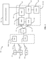
- FIG. 1 illustrates an architecture of a system 100 of a network in accordance with some embodiments.
- the system 100 is shown to include a user equipment (UE) 101, a UE 102, and a UE 103.
- the UEs 101, 102 and 103 are illustrated as smartphones (e.g., handheld touchscreen mobile computing devices connectable to one or more cellular networks), but may also comprise any mobile or non-mobile computing device, such as Personal Data Assistants (PDAs), pagers, laptop computers, desktop computers, wireless handsets, or any computing device including a wireless communications interface.
- PDAs Personal Data Assistants
- pagers pagers
- laptop computers desktop computers
- wireless handsets or any computing device including a wireless communications interface.
- any of the UEs 101, 102 and 103 can comprise an Internet of Things (IoT) UE, which can comprise a network access layer designed for low-power IoT applications utilizing short-lived UE connections.
- An loT UE can utilize technologies such as machine-to-machine (M2M) or machine-type communications (MTC) for exchanging data with an MTC server or device via a public land mobile network (PLMN), Proximity-Based Service (ProSe) or device-to-device (D2D) communication, sensor networks, or loT networks.
- M2M or MTC exchange of data may be a machine-initiated exchange of data.
- loT network describes interconnecting loT UEs, which may include uniquely identifiable embedded computing devices (within the Internet infrastructure), with short-lived connections.
- the loT UEs may execute background applications (e.g., keep-alive messages, status updates, etc.) to facilitate the connections of the loT network.
- the UEs 101, 102 and 103 may be configured to connect, e.g., communicatively couple, with a radio access network (RAN) 110 - the RAN 110 may be, for example, an Evolved Universal Mobile Telecommunications System (UMTS) Terrestrial Radio Access Network (EUTRAN), a NextGen RAN (NG RAN), or some other type of RAN.
- RAN radio access network
- UMTS Evolved Universal Mobile Telecommunications System
- EUTRAN Evolved Universal Mobile Telecommunications System
- NG RAN NextGen RAN
- the UEs 101, 102 and 103 utilize connections 104, 105 and 106, respectively, each of which comprises a physical communications interface or layer (discussed in further detail below); in this example, the connections 103 and 104 are illustrated as an air interface to enable communicative coupling, and can be consistent with cellular communications protocols, such as a Global System for Mobile Communications (GSM) protocol, a code-division multiple access (CDMA) network protocol, a Push-to-Talk (PTT) protocol, a PTT over Cellular (POC) protocol, a Universal Mobile Telecommunications System (UMTS) protocol, a 3GPP Long Term Evolution (LTE) protocol, a fifth generation (5G) protocol, a New Radio (NR) protocol, and the like.
- GSM Global System for Mobile Communications
- CDMA code-division multiple access
- PTT Push-to-Talk
- POC PTT over Cellular
- UMTS Universal Mobile Telecommunications System
- LTE Long Term Evolution
- 5G fifth generation
- NR
- the UEs 101 and 102 may further directly exchange communication data via a ProSe interface 107.
- the ProSe interface 107 may alternatively be referred to as a sidelink interface comprising one or more logical channels, including but not limited to a Physical Sidelink Control Channel (PSCCH), a Physical Sidelink Shared Channel (PSSCH), a Physical Sidelink Discovery Channel (PSDCH), and a Physical Sidelink Broadcast Channel (PSBCH).
- PSCCH Physical Sidelink Control Channel
- PSSCH Physical Sidelink Shared Channel
- PSDCH Physical Sidelink Discovery Channel
- PSBCH Physical Sidelink Broadcast Channel
- the RAN 110 can include one or more Transmission Reception Points (TRPs) 111 and 112 that enable the connections 104, 105 and 106.
- TRPs Transmission Reception Points
- Any of the TRPs 111 and 112 can be a part of a base station (BS), a NodeB, an evolved NodeB (eNB), a next Generation NodeB (gNB), a RAN node, and so forth, and can comprise ground stations (e.g., terrestrial access points) or satellite stations providing coverage within a geographic area (e.g., a cell).
- the TRPs 111 and 112 can supports the MU-MIMO operation.
- any of the TRPs 111 and 112 can terminate the air interface protocol and can be the first point of contact for the UEs 101, 102 and 103.
- any of the TRPs 111 and 112 can fulfill various logical functions for the RAN 110 including, but not limited to, radio network controller (RNC) functions such as radio bearer management, uplink and downlink dynamic radio resource management and data packet scheduling, and mobility management.
- RNC radio network controller
- the UEs 101, 102 and 103 can be configured to communicate using Orthogonal Frequency-Division Multiplexing (OFDM) communication signals with each other or with any of the TRPs 111 and 112 over a multicarrier communication channel in accordance various communication techniques, such as, but not limited to, an Orthogonal Frequency-Division Multiple Access (OFDMA) communication technique (e.g., for downlink communications) or a Single Carrier Frequency Division Multiple Access (SC-FDMA) communication technique (e.g., for uplink and ProSe or sidelink communications), although the scope of the embodiments is not limited in this respect.
- OFDM signals can comprise a plurality of orthogonal subcarriers.
- a downlink resource grid can be used for downlink transmissions from any of the TRPs 111 and 112 to the UEs 101, 102 and 103, while uplink transmissions can utilize similar techniques.
- the grid can be a time-frequency grid, called a resource grid or time-frequency resource grid, which is the physical resource in the downlink in each slot.
- a time-frequency plane representation is a common practice for OFDM systems, which makes it intuitive for radio resource allocation.
- Each column and each row of the resource grid corresponds to one OFDM symbol and one OFDM subcarrier, respectively.
- the duration of the resource grid in the time domain corresponds to one slot in a radio frame.
- the smallest time-frequency unit in a resource grid is denoted as a resource element.
- Each resource grid comprises a number of resource blocks, which describe the mapping of certain physical channels to resource elements.
- Each resource block comprises a collection of resource elements; in the frequency domain, this may represent the smallest quantity of resources that currently can be allocated.
- the physical downlink shared channel may carry user data and higher-layer signaling to the UEs 101, 102 and 103.
- the physical downlink control channel (PDCCH) may carry information about the transport format and resource allocations related to the PDSCH channel, among other things. It may also inform the UEs 101, 102 and 103 about the transport format, resource allocation, and H-ARQ (Hybrid Automatic Repeat Request) information related to the uplink shared channel.
- downlink scheduling (assigning control and shared channel resource blocks to the UEs within a cell) may be performed at any of the TRPs 111 and 112 based on channel quality information fed back from any of the UEs 101, 102 and 103.
- the downlink resource assignment information may be sent on the PDCCH used for (e.g., assigned to) each of the UEs 101, 102 and 103.
- the PDCCH may use control channel elements (CCEs) to convey the control information.
- CCEs control channel elements
- the PDCCH complex-valued symbols may first be organized into quadruplets, which may then be permuted using a sub-block interleaver for rate matching.
- Each PDCCH may be transmitted using one or more of these CCEs, where each CCE may correspond to nine sets of four physical resource elements known as resource element groups (REGs).
- RAGs resource element groups
- QPSK Quadrature Phase Shift Keying
- the PDCCH can be transmitted using one or more CCEs, depending on the size of the downlink control information (DCI) and the channel condition.
- DCI downlink control information
- There can be four or more different PDCCH formats defined in LTE with different numbers of CCEs (e.g., aggregation level, L 1, 2, 4, or 8).
- Some embodiments may use concepts for resource allocation for control channel information that are an extension of the above-described concepts.
- some embodiments may utilize an enhanced physical downlink control channel (EPDCCH) that uses PDSCH resources for control information transmission.
- the EPDCCH may be transmitted using one or more enhanced the control channel elements (ECCEs). Similar to above, each ECCE may correspond to nine sets of four physical resource elements known as an enhanced resource element groups (EREGs). An ECCE may have other numbers of EREGs in some situations.
- EPCCH enhanced physical downlink control channel
- ECCEs enhanced the control channel elements
- each ECCE may correspond to nine sets of four physical resource elements known as an enhanced resource element groups (EREGs).
- EREGs enhanced resource element groups
- An ECCE may have other numbers of EREGs in some situations.
- the RAN 110 is shown to be communicatively coupled to a core network (CN) 120-via an S1 interface 113.
- the CN 120 may be an evolved packet core (EPC) network, a NextGen Packet Core (NPC) network, or some other type of CN.
- EPC evolved packet core
- NPC NextGen Packet Core
- the S1 interface 113 is split into two parts: the S1-U interface 114, which carries traffic data between the TRPs 111 and 112 and the serving gateway (S-GW) 122, and the S1-mobility management entity (MME) interface 115, which is a signaling interface between the TRPs 111 and 112 and MMEs 121.
- S-GW serving gateway
- MME S1-mobility management entity
- the CN 120 comprises the MMEs 121, the S-GW 122, the Packet Data Network (PDN) Gateway (P-GW) 123, and a home subscriber server (HSS) 124.
- the MMEs 121 may be similar in function to the control plane of legacy Serving General Packet Radio Service (GPRS) Support Nodes (SGSN).
- the MMEs 121 may manage mobility aspects in access such as gateway selection and tracking area list management.
- the HSS 124 may comprise a database for network users, including subscription-related information to support the network entities' handling of communication sessions.
- the CN 120 may comprise one or several HSSs 124, depending on the number of mobile subscribers, on the capacity of the equipment, on the organization of the network, etc.
- the HSS 124 can provide support for routing/roaming, authentication, authorization, naming/addressing resolution, location dependencies, etc.
- the S-GW 122 may terminate the S1 interface 113 towards the RAN 110, and route data packets between the RAN 110 and the CN 120.
- the S-GW 122 may be a local mobility anchor point for inter-TRP handovers and also may provide an anchor for inter-3GPP mobility. Other responsibilities may include lawful intercept, charging, and some policy enforcement.
- the P-GW 123 may terminate a SGi interface toward a PDN.
- the P-GW 123 may route data packets between the EPC network 123 and external networks such as a network including the application server 130 (alternatively referred to as application function (AF)) via an Internet Protocol (IP) interface 125.
- the application server 130 may be an element offering applications that use IP bearer resources with the core network (e.g., UMTS Packet Services (PS) domain, LTE PS data services, etc.).
- PS UMTS Packet Services
- LTE PS data services etc.
- the P-GW 123 is shown to be communicatively coupled to an application server 130 via an IP communications interface 125.
- the application server 130 can also be configured to support one or more communication services (e.g., Voice-over-Internet Protocol (VoIP) sessions, PTT sessions, group communication sessions, social networking services, etc.) for the UEs 101, 102 and 103 via the CN 120.
- VoIP Voice-over-Internet Protocol
- PTT sessions PTT sessions
- group communication sessions social networking services, etc.
- the P-GW 123 may further be a node for policy enforcement and charging data collection.
- Policy and Charging Enforcement Function (PCRF) 126 is the policy and charging control element of the CN 120.
- PCRF Policy and Charging Enforcement Function
- HPLMN Home Public Land Mobile Network
- IP-CAN Internet Protocol Connectivity Access Network
- HPLMN Home Public Land Mobile Network
- V-PCRF Visited PCRF
- VPLMN Visited Public Land Mobile Network
- the PCRF 126 may be communicatively coupled to the application server 130 via the P-GW 123.
- the application server 130 may signal the PCRF 126 to indicate a new service flow and select the appropriate Quality of Service (QoS) and charging parameters.
- the PCRF 126 may provision this rule into a Policy and Charging Enforcement Function (PCEF) (not shown) with the appropriate traffic flow template (TFT) and QoS class of identifier (QCI), which commences the QoS and charging as specified by the application server 130.
- PCEF Policy and Charging Enforcement Function
- TFT traffic flow template
- QCI QoS class of identifier
- Fig. 1 The quantity of devices and/or networks illustrated in Fig. 1 is provided for explanatory purposes only. In practice, there may be additional devices and/or networks, fewer devices and/or networks, different devices and/or networks, or differently arranged devices and/or networks than illustrated in Fig. 1 . Alternatively or additionally, one or more of the devices of system 100 may perform one or more functions described as being performed by another one or more of the devices of system 100. Furthermore, while “direct" connections are shown in Fig. 1 , these connections should be interpreted as logical communication pathways, and in practice, one or more intervening devices (e.g., routers, gateways, modems, switches, hubs, etc.) may be present.
- intervening devices e.g., routers, gateways, modems, switches, hubs, etc.
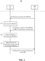
- FIG. 2 is a flow chart showing operations for interference measurement based on downlink beam management reference signals (DL BM-RSs) in accordance with some embodiments of the disclosure.
- DL BM-RSs downlink beam management reference signals
- the beam management will be performed at both the TRP side and the UE side to acquire and maintain optimal TRP and UE beams for communication.
- the beam management may include three procedures: P-1, P-2 and P-3.
- P-1 is to obtain the initial TRP Tx (transmit) beam and UE Rx (receive) beam.
- P-2 is to enable the TRP Tx beam refinement and
- P-3 is to enable the UE Rx beam refinement.
- the TRP needs to periodically broadcast beam-formed reference signals to UEs within a cell served by the TRP.
- the DL BM-RSs are periodically broadcast by the TRP to the UEs within a cell in the beam management procedure P-1 for initial beam acquisition.
- the DL BM-RSs may include a CSI-RS or a Demodulation Reference Signal (DM-RS). Since the CSI-RS for the beam management procedure P-1 is beam-formed and periodically transmitted to the UE, which is non-zero power based, the CSI-RS for the beam management procedure P-1 can be also utilized as a periodic IMR based on NZP CSI-RS. That is, the intra-cell interference measurement can be realized by using the periodic NZP CSI-RS broadcast by the TRP during the beam management procedure P-1. In this way, the overhead for the intra-cell interference measurement can be reduced since it is not necessary to allocate a separate CSI-RS for the purpose of intra-cell interference measurement.
- DM-RS Demodulation Reference Signal
- the intra-cell interference measurement based on the channel estimation and the interference emulation could be simplified because the NZP CSI-RSs transmitted to the respective aggressor UEs have been known to the victim UE.
- the TRP can indicate to the victim UE the interference from which aggressor UEs should be measured, or in other words, which NZP CSI-RSs should be measured.
- the victim UE will measure the interference based on the NZP CSI-RSs sent to the respective aggressor UEs and feedback the interference measurement result to the TRP.
- the indication of the NZP CSI-RSs to be measured for interference is UE specific and could be dynamically changed.
- the victim UE should not perform the interference measurement based on the periodic NZP CSI-RSs. Otherwise, the UE should perform the interference measurement based on the corresponding NZP CSI-RSs as indicated.
- the TRP 111 may broadcast periodic BM-RSs to the UEs in the cell.
- the periodic BM-RSs are to be utilized by the TRP 111 during the beam management procedure P-1 to perform an initial beam acquisition for respective UEs in the cell.
- the UE 101 may decode the periodic BM-RSs received from the TRP 111 so as to facilitate the TRP 111 to realize the initial beam acquisition.
- these periodic BM-RSs may be also utilized as the IMR for the UE 101 to perform the intra-cell interference measurement.
- the UE 101 may measure the intra-cell interference from other UEs in the cell based on the decoded periodic BM-RSs.
- the periodic BM-RSs may include periodic NZP CSI-RSs.
- the intra-cell interference of the victim UE may be measured based on the channel estimation with the NZP CSI-RSs of one or more aggressor UEs and the interference emulation as described above.
- the UE 101 may report the measured interference from each aggressor UE;, i.e. R;, to the TRP 111.
- the TRP 111 may perform the interference emulation for any combination of aggressor UEs and then determine appropriate approaches to handle the interference.
- the interference emulation may be performed at the UE side.
- the UE 101 may generate an interference report including the measured interference of a certain combination of one or more aggressor UEs and send the interference report to the TRP.
- the victim UE may select a subset of the other UEs in the cell as the aggressor UEs to measure the intra-cell interference or the TRP may indicate the victim UE to select a subset of the other UEs in the cell as the aggressor UEs to measure the intra-cell interference. Accordingly, the victim UE may select a respective subset of the decoded BM-RSs as the IMR to measure the intra-cell interference from the selected subset of the other UEs in the cell.
- the UE 101 may select a subset of the decoded BM-RSs corresponding to the selected subset of the other UEs in the cell so as to measure the intra-cell interference from the selected subset of the other UEs in the cell.
- the UE 101 may determine the interference from which of the other UEs in the cell should be measured and thus determine which of the decoded BM-RSs should be utilized as the IMR for the intra-cell interference measurement, based on the desire of the UE 101 itself.
- the UE 101 may select the subset of the decoded BM-RSs for the intra-cell interference measurement according to an indication from the TRP 111.
- the TRP 111 may encode an indication and transmit the encoded indication to the UE 101 to indicate the interference from which of the other UEs in the cell should be measured. Since each UE in the cell has a corresponding beam management reference signal specific to the UE, the indication from the TRP is actually to indicate which BM-RSs should be utilized as the IMR to measure the intra-cell interference of the UE.
- the UE 101 may select a subset of the decoded BM-RSs to measure the intra-cell interference from a respective subset of the other UEs in the cell.
- the indication may be UE specific and may be dynamically configured by the TRP 111 via higher layer signaling or downlink control information (DCI).
- DCI downlink control information
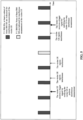
- Fig. 3 shows an example time chart of interference measurement and report based on periodic DL BM-RSs in accordance with some embodiments of the disclosure.
- the BM-RSs are periodically broadcast by the TRP to the UEs in the cell. If the victim UE receives an indication from the TRP for indicating the subset of the BM-RSs for the intra-cell interference measurement, the victim UE should perform the intra-cell interference measurement based on the subset of the BM-RSs and report the measured interference to the TRP periodically. Otherwise, if no BM-RSs are indicated for the intra-cell interference measurement, the UE should not perform the intra-cell interference measurement based on the periodic BM-RSs.
- the intra-cell interference measurement based on the P-1 BM-RSs is performed periodically and the interference report is sent to the TRP periodically.
- the victim UE may conduct the intra-cell interference measurement based on semi-persistent downlink beam management reference signals instead of periodic DL BM-RSs for improved flexibility.
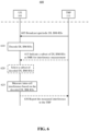
- Fig. 4 is a flow chart showing operations for interference measurement based on semi-persistent DL BM-RSs in accordance with some embodiments of the disclosure.
- the operations 405, 410, 415, 420 and 430 in the flow chart of Fig. 4 are the same as the operations 205, 210, 215, 220 and 230 in the flow chart of Fig. 2 , and thus the detailed description related to these operations will be omitted for conciseness.
- the TRP 111 can control the UE 101 to perform or stop the interference measurement by encoding a trigger signal and transmitting the encoded trigger signal to the UE 101 at 435.
- the UE 101 may measure the intra-cell interference based on the BM-RSs in response to the trigger signal for notifying the UE 101 to perform the interference measurement or stop the intra-cell interference measurement in response to the trigger signal for notifying the UE 101 to stop the interference measurement.
- the periodic BM-RSs for the beam management procedure P-1 are semi-persistently utilized as the IMR for the victim UE to perform the intra-cell interference measurement more flexibly.
- Fig. 5 shows an example time chart of interference measurement and report based on semi-persistent DL BM-RSs in accordance with some embodiments of the disclosure.
- the victim UE may perform or stop the interference measurement based on the periodic P-1 BM-RSs in response to receiving a trigger signal for notifying the victim UE to perform or stop the interference measurement.
- the beam management procedure P-2 is to refine the TRP Tx beam for downlink transmission.
- the TRP sends beam management reference signals (e.g. CSI-RS) to be measured by the UE and the UE needs to feedback the received signals to complete the beam refinement.
- the procedure P-2 may be performed aperiodically.
- the TRP may broadcast aperiodic BM-RSs to the UE during the procedure P-2.
- the aperiodic BM-RSs can also be reused as the IMR for the UE to perform the intra-cell interference measurement.
- Fig. 6 is a flow chart showing operations for interference measurement based on aperiodic downlink beam management reference signals in accordance with some embodiments of the disclosure.
- the operations in the flow chart of Fig. 6 are similar to the operations in the flow chart of Fig. 2 , except that the P-2 aperiodic BM-RSs instead of the P-1 periodic BM-RSs are utilized as the IMR for intra-cell interference measurement.
- the P-2 aperiodic BM-RSs instead of the P-1 periodic BM-RSs are utilized as the IMR for intra-cell interference measurement.
- the UE can report the intra-cell interference aperiodically. For example, the UE can measure and report the intra-cell interference in response to a trigger signal configured by the TRP for triggering the interference measurement.
- Fig. 7 shows an example time chart of interference measurement and report based on aperiodic BM-RSs in accordance with some embodiments of the disclosure.
- the aperiodic NZP CSI-RSs for the P-2 beam management procedure may be also indicated as the aperiodic IMR for the intra-cell interference measurement. In this way, the flexibility of the intra-cell interference can be further increased, and the overhead for the intra-cell interference can be reduced.
- the UE may be subject to interference from other UEs in a neighbor cell, especially when the UE and the TRP are working in a dynamic Time Division Duplexing (TDD) mode.
- TDD Time Division Duplexing
- a downlink transmission of a UE in a cell may be subject to interference from an uplink transmission of other UEs in a neighbor cell.
- the interference from the other UEs in the neighbor cell may be more significant than the intra-cell interference of the UE.
- it may be necessary to measure the interference from the other UEs in the neighbor cell.
- UL beam management has been considered to maintain a good UE-TRP beam pair.
- the UEs could directly reuse the DL Rx beam to be the UL Tx beam.
- some uplink beam sweeping operations should be used to help the UEs to determine the best UL Tx beam.
- the TRP cannot easily determine which beam is to be used to receive the UL signal.
- the UL beam management are to be supported for the case when partial or no beam correspondence can be guaranteed.
- UL beam management reference signals are used to perform the UL beam management.
- the UL beam management reference signals transmitted by the other UEs in the neighbor cell can also be utilized as the IMR for the UE to measure the interference from the other UEs in the neighbor cell.
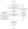
- Fig. 8 is a flow chart showing operations at the UE 101 for interference measurement based on both uplink beam management reference signals (UL BM-RSs) and DL BM-RSs in accordance with some embodiments of the disclosure.
- UL BM-RSs uplink beam management reference signals
- DL BM-RSs downlink beam management reference signals
- the UE 101 and the TRP 111 may just measure the intra-cell interference from other UEs in a same cell based on DL BM-RSs as described above. Specifically, the UE 101 may decode the DL BM-RSs broadcast by the TRP 111 for DL beam management at 815 and then measure the intra-cell interference from other UEs in the same cell based on the decoded DL BM-RSs at 820. For the details of the operations 815 and 820, references may be made to the description about the foregoing embodiments as shown in FIG. 2 to FIG. 7 .
- the interference from other UEs in the neighbor cell may be a main interference source and thus need to be measured so as to accurately estimate the total interference.
- the UE 101 decodes UL BM-RSs transmitted by other UEs in the neighbor cell for UL beam management.
- the UL BM-RSs may include a Sounding Reference Signal (SRS), a Physical Uplink Control Chanel (PUCCH) signal or a Physical Random Access Chanel (PRACH) signal.
- SRS Sounding Reference Signal
- PUCCH Physical Uplink Control Chanel
- PRACH Physical Random Access Chanel
- the UE 101 can measure the interference from the other UEs in the neighbor cell with the UL DM-RSs as the IMR at 835 at a same timing as that of measuring the intra-cell interference from the other UEs in the cell based on the DL DM-RSs. According to the invention, if the network is not synchronized, i.e.
- a measurement gap is determined at 840 based on a timing difference between the cell and the neighbor cell.
- the measurement gap is a gap between a timing of measuring the interference from the other UEs in the cell and a timing of measuring the interference from the other UEs in the neighbor cell.
- the UE 101 measures the interference from the other UEs in the neighbor cell based on the decoded UL BM-RSs at a timing scheduled according to the determined measurement gap and the timing of measuring the interference from the other UEs in the cell at 845.
- both the interference from the other UEs in the cell and the interference from the other UEs in the neighbor cell can be measured with the DL BM-RSs and the UL BM-RSs respectively.
- the UE 101 can report both the interference from the other UEs in the cell and the interference from the other UEs in the neighbor cell to the TRP 111 at 850.
- FIG. 9 illustrates example components of a device 900 in accordance with some embodiments.
- the device 900 may include application circuitry 902, baseband circuitry 904, Radio Frequency (RF) circuitry 906, front-end module (FEM) circuitry 908, one or more antennas 910, and power management circuitry (PMC) 912 coupled together at least as shown.
- the components of the illustrated device 900 may be included in a UE or a TRP.
- the device 900 may include less elements (e.g., a RAN node may not utilize application circuitry 902, and instead include a processor/controller to process IP data received from an EPC).
- the device 900 may include additional elements such as, for example, memory/storage, display, camera, sensor, or input/output (I/O) interface.
- additional elements such as, for example, memory/storage, display, camera, sensor, or input/output (I/O) interface.
- the components described below may be included in more than one device (e.g., said circuitries may be separately included in more than one device for Cloud-RAN (C-RAN) implementations).
- C-RAN Cloud-RAN
- the application circuitry 902 may include one or more application processors.
- the application circuitry 902 may include circuitry such as, but not limited to, one or more single-core or multi-core processors.
- the processor(s) may include any combination of general-purpose processors and dedicated processors (e.g., graphics processors, application processors, etc.).
- the processors may be coupled with or may include memory/storage and may be configured to execute instructions stored in the memory/storage to enable various applications or operating systems to run on the device 900.
- processors of application circuitry 902 may process IP data packets received from an EPC.
- the baseband circuitry 904 may include circuitry such as, but not limited to, one or more single-core or multi-core processors.
- the baseband circuitry 904 may include one or more baseband processors or control logic to process baseband signals received from a receive signal path of the RF circuitry 906 and to generate baseband signals for a transmit signal path of the RF circuitry 906.
- Baseband processing circuitry 904 may interface with the application circuitry 902 for generation and processing of the baseband signals and for controlling operations of the RF circuitry 906.
- the baseband circuitry 904 may include a third generation (3G) baseband processor 904A, a fourth generation (4G) baseband processor 904B, a fifth generation (5G) baseband processor 904C, or other baseband processor(s) 904D for other existing generations, generations in development or to be developed in the future (e.g., second generation (2G), sixth generation (6G), etc.).
- the baseband circuitry 904 e.g., one or more of baseband processors 904A-D
- baseband processors 904A-D may be included in modules stored in the memory 904G and executed via a Central Processing Unit (CPU) 904E.
- the radio control functions may include, but are not limited to, signal modulation/demodulation, encoding/decoding, radio frequency shifting, etc.
- modulation/demodulation circuitry of the baseband circuitry 904 may include Fast-Fourier Transform (FFT), precoding, or constellation mapping/demapping functionality.
- FFT Fast-Fourier Transform
- encoding/decoding circuitry of the baseband circuitry 904 may include convolution, tail-biting convolution, turbo, Viterbi, or Low Density Parity Check (LDPC) encoder/decoder functionality.
- LDPC Low Density Parity Check
- the baseband circuitry 904 may include one or more audio digital signal processor(s) (DSP) 904F.
- the audio DSP(s) 904F may be include elements for compression/decompression and echo cancellation and may include other suitable processing elements in other embodiments.
- Components of the baseband circuitry may be suitably combined in a single chip, a single chipset, or disposed on a same circuit board in some embodiments.
- some or all of the constituent components of the baseband circuitry 904 and the application circuitry 902 may be implemented together such as, for example, on a system on a chip (SOC).
- SOC system on a chip
- the baseband circuitry 904 may provide for communication compatible with one or more radio technologies.
- the baseband circuitry 904 may support communication with an evolved universal terrestrial radio access network (EUTRAN) or other wireless metropolitan area networks (WMAN), a wireless local area network (WLAN), a wireless personal area network (WPAN).
- EUTRAN evolved universal terrestrial radio access network
- WMAN wireless metropolitan area networks
- WLAN wireless local area network
- WPAN wireless personal area network
- multi-mode baseband circuitry Embodiments in which the baseband circuitry 904 is configured to support radio communications of more than one wireless protocol.
- RF circuitry 906 may enable communication with wireless networks using modulated electromagnetic radiation through a non-solid medium.
- the RF circuitry 906 may include switches, filters, amplifiers, etc. to facilitate the communication with the wireless network.
- RF circuitry 906 may include a receive signal path which may include circuitry to down-convert RF signals received from the FEM circuitry 908 and provide baseband signals to the baseband circuitry 904.
- RF circuitry 906 may also include a transmit signal path which may include circuitry to up-convert baseband signals provided by the baseband circuitry 904 and provide RF output signals to the FEM circuitry 908 for transmission.
- the receive signal path of the RF circuitry 906 may include mixer circuitry 906a, amplifier circuitry 906b and filter circuitry 906c.
- the transmit signal path of the RF circuitry 906 may include filter circuitry 906c and mixer circuitry 906a.
- RF circuitry 906 may also include synthesizer circuitry 906d for synthesizing a frequency for use by the mixer circuitry 906a of the receive signal path and the transmit signal path.
- the mixer circuitry 906a of the receive signal path may be configured to down-convert RF signals received from the FEM circuitry 908 based on the synthesized frequency provided by synthesizer circuitry 906d.
- the amplifier circuitry 906b may be configured to amplify the down-converted signals and the filter circuitry 906c may be a low-pass filter (LPF) or band-pass filter (BPF) configured to remove unwanted signals from the down-converted signals to generate output baseband signals.
- Output baseband signals may be provided to the baseband circuitry 904 for further processing.
- the output baseband signals may be zero-frequency baseband signals, although this is not a requirement.
- mixer circuitry 906a of the receive signal path may comprise passive mixers, although the scope of the embodiments is not limited in this respect.
- the mixer circuitry 906a of the transmit signal path may be configured to up-convert input baseband signals based on the synthesized frequency provided by the synthesizer circuitry 906d to generate RF output signals for the FEM circuitry 908.
- the baseband signals may be provided by the baseband circuitry 904 and may be filtered by filter circuitry 906c.
- the mixer circuitry 906a of the receive signal path and the mixer circuitry 906a of the transmit signal path may include two or more mixers and may be arranged for quadrature down-conversion and up-conversion, respectively.
- the mixer circuitry 906a of the receive signal path and the mixer circuitry 906a of the transmit signal path may include two or more mixers and may be arranged for image rejection (e.g., Hartley image rejection).
- the mixer circuitry 906a of the receive signal path and the mixer circuitry 906a may be arranged for direct down-conversion and direct up-conversion, respectively.
- the mixer circuitry 906a of the receive signal path and the mixer circuitry 906a of the transmit signal path may be configured for super-heterodyne operation.
- the output baseband signals and the input baseband signals may be analog baseband signals, although the scope of the embodiments is not limited in this respect.
- the output baseband signals and the input baseband signals may be digital baseband signals.
- the RF circuitry 906 may include analog-to-digital converter (ADC) and digital-to-analog converter (DAC) circuitry and the baseband circuitry 904 may include a digital baseband interface to communicate with the RF circuitry 906.
- ADC analog-to-digital converter
- DAC digital-to-analog converter
- a separate radio IC circuitry may be provided for processing signals for each spectrum, although the scope of the embodiments is not limited in this respect.
- the synthesizer circuitry 906d may be a fractional-N synthesizer or a fractional N/N+1 synthesizer, although the scope of the embodiments is not limited in this respect as other types of frequency synthesizers may be suitable.
- synthesizer circuitry 906d may be a delta-sigma synthesizer, a frequency multiplier, or a synthesizer comprising a phase-locked loop with a frequency divider.
- the synthesizer circuitry 906d may be configured to synthesize an output frequency for use by the mixer circuitry 906a of the RF circuitry 906 based on a frequency input and a divider control input. In some embodiments, the synthesizer circuitry 906d may be a fractional N/N+1 synthesizer.
- frequency input may be provided by a voltage controlled oscillator (VCO), although that is not a requirement.
- VCO voltage controlled oscillator
- Divider control input may be provided by either the baseband circuitry 904 or the applications processor 902 depending on the desired output frequency.
- a divider control input (e.g., N) may be determined from a look-up table based on a channel indicated by the applications processor 902.
- Synthesizer circuitry 906d of the RF circuitry 906 may include a divider, a delay-locked loop (DLL), a multiplexer and a phase accumulator.
- the divider may be a dual modulus divider (DMD) and the phase accumulator may be a digital phase accumulator (DPA).
- the DMD may be configured to divide the input signal by either N or N+1 (e.g., based on a carry out) to provide a fractional division ratio.
- the DLL may include a set of cascaded, tunable, delay elements, a phase detector, a charge pump and a D-type flip-flop.
- the delay elements may be configured to break a VCO period up into Nd equal packets of phase, where Nd is the number of delay elements in the delay line.
- Nd is the number of delay elements in the delay line.
- synthesizer circuitry 906d may be configured to generate a carrier frequency as the output frequency, while in other embodiments, the output frequency may be a multiple of the carrier frequency (e.g., twice the carrier frequency, four times the carrier frequency) and used in conjunction with quadrature generator and divider circuitry to generate multiple signals at the carrier frequency with multiple different phases with respect to each other.
- the output frequency may be a LO frequency (fLO).
- the RF circuitry 906 may include an IQ/polar converter.
- FEM circuitry 908 may include a receive signal path which may include circuitry configured to operate on RF signals received from one or more antennas 910, amplify the received signals and provide the amplified versions of the received signals to the RF circuitry 906 for further processing.
- FEM circuitry 908 may also include a transmit signal path which may include circuitry configured to amplify signals for transmission provided by the RF circuitry 906 for transmission by one or more of the one or more antennas 910.
- the amplification through the transmit or receive signal paths may be done solely in the RF circuitry 906, solely in the FEM 908, or in both the RF circuitry 906 and the FEM 908.
- the FEM circuitry 908 may include a TX/RX switch to switch between transmit mode and receive mode operation.
- the FEM circuitry may include a receive signal path and a transmit signal path.
- the receive signal path of the FEM circuitry may include an LNA to amplify received RF signals and provide the amplified received RF signals as an output (e.g., to the RF circuitry 906).
- the transmit signal path of the FEM circuitry 908 may include a power amplifier (PA) to amplify input RF signals (e.g., provided by RF circuitry 906), and one or more filters to generate RF signals for subsequent transmission (e.g., by one or more of the one or more antennas 910).
- PA power amplifier
- the PMC 912 may manage power provided to the baseband circuitry 904.
- the PMC 912 may control power-source selection, voltage scaling, battery charging, or DC-to-DC conversion.
- the PMC 912 may often be included when the device 900 is capable of being powered by a battery, for example, when the device is included in a UE.
- the PMC 912 may increase the power conversion efficiency while providing desirable implementation size and heat dissipation characteristics.
- FIG. 9 shows the PMC 912 coupled only with the baseband circuitry 904.
- the PMC 912 may be additionally or alternatively coupled with, and perform similar power management operations for, other components such as, but not limited to, application circuitry 902, RF circuitry 906, or FEM 908.
- the PMC 912 may control, or otherwise be part of, various power saving mechanisms of the device 900. For example, if the device 900 is in an RRC_Connected state, where it is still connected to the RAN node as it expects to receive traffic shortly, then it may enter a state known as Discontinuous Reception Mode (DRX) after a period of inactivity. During this state, the device 900 may power down for brief intervals of time and thus save power.
- DRX Discontinuous Reception Mode
- the device 900 may transition off to an RRC_Idle state, where it disconnects from the network and does not perform operations such as channel quality feedback, handover, etc.
- the device 900 goes into a very low power state and it performs paging where again it periodically wakes up to listen to the network and then powers down again.
- the device 900 may not receive data in this state, in order to receive data, it may transition back to RRC_Connected state.
- An additional power saving mode may allow a device to be unavailable to the network for periods longer than a paging interval (ranging from seconds to a few hours). During this time, the device is totally unreachable to the network and may power down completely. Any data sent during this time incurs a large delay and it is assumed the delay is acceptable.
- Processors of the application circuitry 902 and processors of the baseband circuitry 904 may be used to execute elements of one or more instances of a protocol stack.
- processors of the baseband circuitry 904 alone or in combination, may be used execute Layer 3, Layer 2, or Layer 1 functionality, while processors of the application circuitry 904 may utilize data (e.g., packet data) received from these layers and further execute Layer 4 functionality (e.g., transmission communication protocol (TCP) and user datagram protocol (UDP) layers).
- Layer 3 may comprise a radio resource control (RRC) layer, described in further detail below.
- RRC radio resource control
- Layer 2 may comprise a medium access control (MAC) layer, a radio link control (RLC) layer, and a packet data convergence protocol (PDCP) layer, described in further detail below.
- Layer 1 may comprise a physical (PHY) layer of a UE/RAN node, described in further detail below.
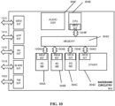
- FIG. 10 illustrates example interfaces of baseband circuitry in accordance with some embodiments.
- the baseband circuitry 904 of FIG. 9 may comprise processors 904A-904E and a memory 904G utilized by said processors.
- Each of the processors 904A-904E may include a memory interface, 1004A-1004E, respectively, to send/receive data to/from the memory 904G.
- the baseband circuitry 904 may further include one or more interfaces to communicatively couple to other circuitries/devices, such as a memory interface 1012 (e.g., an interface to send/receive data to/from memory external to the baseband circuitry 904), an application circuitry interface 1014 (e.g., an interface to send/receive data to/from the application circuitry 902 of FIG. 9 ), an RF circuitry interface 1016 (e.g., an interface to send/receive data to/from RF circuitry 906 of FIG.
- a memory interface 1012 e.g., an interface to send/receive data to/from memory external to the baseband circuitry 904
- an application circuitry interface 1014 e.g., an interface to send/receive data to/from the application circuitry 902 of FIG. 9
- an RF circuitry interface 1016 e.g., an interface to send/receive data to/from RF circuitry 906 of FIG.
- a wireless hardware connectivity interface 1018 e.g., an interface to send/receive data to/from Near Field Communication (NFC) components, Bluetooth ® components (e.g., Bluetooth ® Low Energy), Wi-Fi ® components, and other communication components
- a power management interface 1020 e.g., an interface to send/receive power or control signals to/from the PMC 912.
- FIG. 11 is a block diagram illustrating components, according to some example embodiments, able to read instructions from a machine-readable or computer-readable medium (e.g., a non-transitory machine-readable storage medium) and perform any one or more of the methodologies discussed herein.
- FIG. 11 shows a diagrammatic representation of hardware resources 1100 including one or more processors (or processor cores) 1110, one or more memory/storage devices 1120, and one or more communication resources 1130, each of which may be communicatively coupled via a bus 1140.
- node virtualization e.g., NFV
- a hypervisor 1102 may be executed to provide an execution environment for one or more network slices/sub-slices to utilize the hardware resources 1100
- the processors 1110 may include, for example, a processor 1112 and a processor 1114.
- CPU central processing unit
- RISC reduced instruction set computing
- CISC complex instruction set computing
- GPU graphics processing unit
- DSP digital signal processor
- ASIC application specific integrated circuit
- RFIC radio-frequency integrated circuit
- the memory/storage devices 1120 may include main memory, disk storage, or any suitable combination thereof.
- the memory/storage devices 1120 may include, but are not limited to any type of volatile or non-volatile memory such as dynamic random access memory (DRAM), static random-access memory (SRAM), erasable programmable read-only memory (EPROM), electrically erasable programmable read-only memory (EEPROM), Flash memory, solid-state storage, etc.
- DRAM dynamic random access memory
- SRAM static random-access memory
- EPROM erasable programmable read-only memory
- EEPROM electrically erasable programmable read-only memory
- Flash memory solid-state storage, etc.
- the communication resources 1130 may include interconnection or network interface components or other suitable devices to communicate with one or more peripheral devices 1104 or one or more databases 1106 via a network 1108.
- the communication resources 1130 may include wired communication components (e.g., for coupling via a Universal Serial Bus (USB)), cellular communication components, NFC components, Bluetooth ® components (e.g., Bluetooth ® Low Energy), Wi-Fi ® components, and other communication components.
- wired communication components e.g., for coupling via a Universal Serial Bus (USB)
- cellular communication components e.g., for coupling via a Universal Serial Bus (USB)
- NFC components e.g., NFC components
- Bluetooth ® components e.g., Bluetooth ® Low Energy
- Wi-Fi ® components e.g., Wi-Fi ® components
- Instructions 1150 may comprise software, a program, an application, an applet, an app, or other executable code for causing at least any of the processors 1110 to perform any one or more of the methodologies discussed herein.
- the instructions 1150 may reside, completely or partially, within at least one of the processors 1110 (e.g., within the processor's cache memory), the memory/storage devices 1120, or any suitable combination thereof.
- any portion of the instructions 1150 may be transferred to the hardware resources 1100 from any combination of the peripheral devices 1104 or the databases 1106. Accordingly, the memory of processors 1110, the memory/storage devices 1120, the peripheral devices 1104, and the databases 1106 are examples of computer-readable and machine-readable media.
Landscapes
- Engineering & Computer Science (AREA)
- Computer Networks & Wireless Communication (AREA)
- Signal Processing (AREA)
- Quality & Reliability (AREA)
- Physics & Mathematics (AREA)
- Electromagnetism (AREA)
- Mobile Radio Communication Systems (AREA)
Claims (12)
- Vorrichtung für ein Benutzergerät, UE (101), umfassend Schaltung konfiguriert zum:Decodieren (210) eines oder mehrerer Strahlverwaltungsreferenzsignale, die von einem Übertragungsempfangspunkt, TRP (111), in einer Zelle rundgesendet werden, wobei das eine oder die mehreren Strahlverwaltungsreferenzsignale vom TRP (111) verwendet werden, um Strahlverwaltung für ein oder mehrere jeweilige andere UEs in der Zelle durchzuführen; undMessen von Interferenz von dem einen oder den mehreren anderen UEs in der Zelle basierend auf dem einen oder den mehreren decodiertenStrahlverwaltungsreferenzsignalen,wobei, wenn das UE (101) und der TRP (111) in einem dynamischen Zeitduplexmodus, TDD-Modus, arbeiten, die Schaltung ferner konfiguriert ist zum:Decodieren eines oder mehrerer Uplink-Strahlverwaltungsreferenzsignale, die jeweils von einem oder mehreren anderen UEs in einer Nachbarzelle zur Uplink-Strahlverwaltung übertragen werden; undMessen von Interferenz von dem einen oder den mehreren anderen UEs in der Nachbarzelle basierend auf dem einen oder den mehreren decodierten Uplink-Strahlverwaltungsreferenzsignalen, und wobei, wenn die Zelle und die Nachbarzelle nicht synchronisiert sind, die Schaltung ferner konfiguriert ist zum:Bestimmen einer Messlücke basierend auf einer Zeitdifferenz zwischen der Zelle und der Nachbarzelle; undMessen der Interferenz von dem einen oder den mehreren anderen UEs in der Nachbarzelle zu einem Zeitpunkt, der gemäß der bestimmten Messlücke und einem Zeitpunkt des Messens der Interferenz von dem einen oder den mehreren anderen UEs in der Zelle geplant ist.
- Vorrichtung nach Anspruch 1, wobei die Schaltung ferner konfiguriert ist zum: Auswählen einer Teilmenge des einen oder der mehreren decodierten Strahlverwaltungsreferenzsignale als Interferenzmessressource, IMR, zum Messen von Interferenz von einer jeweiligen Teilmenge des einen oder der mehreren anderen UEs basierend auf der ausgewählten Teilmenge des einen oder der mehreren decodierten Strahlverwaltungsreferenzsignale.
- Vorrichtung nach Anspruch 2, wobei die Schaltung ferner konfiguriert ist zum: Decodieren einer vom TRP empfangenen Anzeige zum Anzeigen der Teilmenge des einen oder der mehreren decodierten Strahlverwaltungsreferenzsignale als die IMR; und
Auswählen der Teilmenge des einen oder der mehreren decodierten Strahlverwaltungsreferenzsignale als die IMR gemäß der Anzeige vom TRP. - Vorrichtung nach einem der Ansprüche 1-3, wobei die Schaltung ferner konfiguriert ist zum:Durchführen einer Kanalschätzung für das UE basierend auf einem Strahlverwaltungsreferenzsignal, das für ein jeweiliges anderes UE des einen oder der mehreren anderen UEs spezifisch ist, um eine geschätzte Kanalcharakteristik H des UE zu erhalten, das Interferenz vom jeweiligen anderen UE unterliegt; undErhalten der Interferenz vom jeweiligen anderen UE als R = H*HH.
- Vorrichtung nach einem der Ansprüche 1-4, wobei das eine oder die mehreren Strahlverwaltungsreferenzsignale ein oder mehrere periodische Strahlverwaltungsreferenzsignale umfassen, die vom TRP rundgesendet werden, um eine anfängliche Strahlerfassung für das eine oder die mehreren jeweiligen anderen UEs in der Zelle durchzuführen.
- Vorrichtung nach Anspruch 5, wobei die Schaltung ferner konfiguriert ist zum:Messen der Interferenz von dem einen oder den mehreren anderen UEs in der Zelle basierend auf dem einen oder den mehreren periodischen Strahlverwaltungsreferenzsignalen als Reaktion auf ein Auslösesignal vom TRP zum Benachrichtigen des UE, die Interferenzmessung durchzuführen; undStoppen des Messens der Interferenz von dem einen oder den mehreren anderen UEs in der Zelle basierend auf dem einen oder den mehreren periodischen Strahlverwaltungsreferenzsignalen als Reaktion auf ein Auslösesignal vom TRP zum Benachrichtigen des UE, die Interferenzmessung zu stoppen.
- Vorrichtung nach einem der Ansprüche 1-6, wobei die Schaltung ferner konfiguriert ist zum:
Erzeugen eines Interferenzberichts, der sowohl die gemessene Interferenz von dem einen oder den mehreren anderen UEs in der Zelle als auch die gemessene Interferenz von dem einen oder den mehreren anderen UEs in der Nachbarzelle beinhaltet; und Senden des Interferenzberichts an den TRP. - Vorrichtung für einen Übertragungsempfangspunkt, TRP (111), umfassend Schaltung konfiguriert zum:Rundsenden (205) eines oder mehrerer Strahlverwaltungsreferenzsignale an ein oder mehrere Benutzergeräte, UEs, in einer Zelle, um Strahlverwaltung für das eine oder die mehreren UEs durchzuführen; undCodieren einer an ein UE in der Zelle zu übertragenden Anzeige zum Anzeigen einer Teilmenge des einen oder der mehreren Strahlverwaltungsreferenzsignale als Interferenzmessressource, IMR, für das UE (101) zum Messen (225) von Interferenz von einer jeweiligen Teilmenge eines oder mehrerer anderer UEs in der Zelle, wobei, wenn das UE und der TRP in einem dynamischen Zeitduplexmodus, TDD-Modus, arbeiten, die Schaltung ferner konfiguriert ist zum:Empfangen, vom UE, eines Interferenzberichts, der sowohl die Interferenz von dem einen oder den mehreren anderen UEs in der Zelle als auch Interferenz von einem oder mehreren anderen UEs in einer Nachbarzelle beinhaltet,wobei die Interferenz von dem einen oder den mehreren anderen UEs in der Nachbarzelle durch das UE basierend auf einem oder mehreren Uplink-Strahlverwaltungsreferenzsignalen gemessen wird, die jeweils von dem einen oder den mehreren anderen UEs in der Nachbarzelle zur Uplink-Strahlverwaltung übertragen werden,und wobei, wenn die Zelle und die Nachbarzelle nicht synchronisiert sind, eine Messlücke basierend auf einer Zeitdifferenz zwischen der Zelle und der Nachbarzelle bestimmt wird und dem UE angezeigt wird, die Interferenz von dem einen oder den mehreren anderen UEs in der Nachbarzelle zu einem Zeitpunkt zu messen, der gemäß der bestimmten Messlücke und einem Zeitpunkt des Messens der Interferenz von dem einen oder den mehreren anderen UEs in der Zelle geplant ist.
- Verfahren, das an einem Benutzergerät, UE (101), durchgeführt wird, umfassend:Decodieren (210) eines oder mehrerer Strahlverwaltungsreferenzsignale, die von einem Übertragungsempfangspunkt, TRP (111), in einer Zelle rundgesendet werden, wobei das eine oder die mehreren Strahlverwaltungsreferenzsignale vom TRP (111) verwendet werden, um Strahlverwaltung für ein oder mehrere jeweilige andere UEs in der Zelle durchzuführen; undMessen von Interferenz von dem einen oder den mehreren anderen UEs in der Zelle basierend auf dem einen oder den mehreren decodiertenStrahlverwaltungsreferenzsignalen, wobei, wenn das UE (101) und der TRP (111) in einem dynamischen Zeitduplexmodus, TDD-Modus, arbeiten, das Verfahren ferner umfasst:Decodieren eines oder mehrerer Uplink-Strahlverwaltungsreferenzsignale, die jeweils von einem oder mehreren anderen UEs in einer Nachbarzelle zur Uplink-Strahlverwaltung übertragen werden; undMessen von Interferenz von dem einen oder den mehreren anderen UEs in der Nachbarzelle basierend auf dem einen oder den mehreren decodierten Uplink-Strahlverwaltungsreferenzsignalen,und wobei, wenn die Zelle und die Nachbarzelle nicht synchronisiert sind, das Verfahren ferner umfasst:Bestimmen einer Messlücke basierend auf einer Zeitdifferenz zwischen der Zelle und der Nachbarzelle; undMessen der Interferenz von dem einen oder den mehreren anderen UEs in der Nachbarzelle zu einem Zeitpunkt, der gemäß der bestimmten Messlücke und einem Zeitpunkt des Messens der Interferenz von dem einen oder den mehreren anderen UEs in der Zelle geplant ist.
- Verfahren, das an einem Übertragungsempfangspunkt, TRP (111), durchgeführt wird, umfassend:Rundsenden eines oder mehrerer Strahlverwaltungsreferenzsignale an ein oder mehrere Benutzergeräte, UEs, in einer Zelle, um Strahlverwaltung für das eine oder die mehreren UEs durchzuführen; undCodieren einer an ein UE (101) in der Zelle zu übertragenden Anzeige zum Anzeigen einer Teilmenge des einen oder der mehreren Strahlverwaltungsreferenzsignale als Interferenzmessressource, IMR, für das UE (101) zum Messen von Interferenz von einer jeweiligen Teilmenge eines oder mehrerer anderer UEs in der Zelle; undunter der Bedingung, dass das UE und der TRP in einem dynamischen Zeitduplexmodus, TDD-Modus, arbeiten, Empfangen, vom UE, eines Interferenzberichts, der sowohl die Interferenz von dem einen oder den mehreren anderen UEs in der Zelle als auch Interferenz von einem oder mehreren anderen UEs in einer Nachbarzelle beinhaltet,wobei die Interferenz von dem einen oder den mehreren anderen UEs in der Nachbarzelle durch das UE basierend auf einem oder mehreren Uplink-Strahlverwaltungsreferenzsignalen gemessen wird, die jeweils von dem einen oder den mehreren anderen UEs in der Nachbarzelle zur Uplink-Strahlverwaltung übertragen werden,und wobei, wenn die Zelle und die Nachbarzelle nicht synchronisiert sind, eine Messlücke basierend auf einer Zeitdifferenz zwischen der Zelle und der Nachbarzelle bestimmt wird und dem UE angezeigt wird, die Interferenz von dem einen oder den mehreren anderen UEs in der Nachbarzelle zu einem Zeitpunkt zu messen, der gemäß der bestimmten Messlücke und einem Zeitpunkt des Messens der Interferenz von dem einen oder den mehreren anderen UEs in der Zelle geplant ist.
- Nichtflüchtiges computerlesbares Medium mit darauf gespeicherten Anweisungen, wobei die Anweisungen, wenn sie von einem oder mehreren Prozessoren an einem Benutzergerät, UE (101), ausgeführt werden, den einen oder die mehreren Prozessoren veranlassen, das Verfahren nach Anspruch 9 durchzuführen.
- Nichtflüchtiges computerlesbares Medium mit darauf gespeicherten Anweisungen, wobei die Anweisungen, wenn sie von einem oder mehreren Prozessoren an einem Übertragungsempfangspunkt, TRP, ausgeführt werden, den einen oder die mehreren Prozessoren veranlassen, das Verfahren nach Anspruch 10 durchzuführen.
Applications Claiming Priority (2)
| Application Number | Priority Date | Filing Date | Title |
|---|---|---|---|
| CN2017082730 | 2017-05-02 | ||
| PCT/CN2018/085318 WO2018202036A1 (en) | 2017-05-02 | 2018-05-02 | Method and apparatus for interference measurement using beam management reference signal |
Publications (3)
| Publication Number | Publication Date |
|---|---|
| EP3620007A1 EP3620007A1 (de) | 2020-03-11 |
| EP3620007A4 EP3620007A4 (de) | 2021-03-31 |
| EP3620007B1 true EP3620007B1 (de) | 2024-03-06 |
Family
ID=64016880
Family Applications (1)
| Application Number | Title | Priority Date | Filing Date |
|---|---|---|---|
| EP18793801.4A Active EP3620007B1 (de) | 2017-05-02 | 2018-05-02 | Verfahren und vorrichtung zur interferenzmessung unter verwendung eines strahlverwaltungsreferenzsignals |
Country Status (4)
| Country | Link |
|---|---|
| US (1) | US11018730B2 (de) |
| EP (1) | EP3620007B1 (de) |
| CN (1) | CN110537387B (de) |
| WO (1) | WO2018202036A1 (de) |
Families Citing this family (17)
| Publication number | Priority date | Publication date | Assignee | Title |
|---|---|---|---|---|
| CN110832803B (zh) * | 2017-05-05 | 2022-11-11 | 瑞典爱立信有限公司 | 用于多用户多入多出的干扰测量和信道状态信息反馈 |
| WO2019157761A1 (en) * | 2018-02-15 | 2019-08-22 | Qualcomm Incorporated | Techniques for activating semi-persistent configuration for channel state indicator resource sets |
| CN110289896A (zh) * | 2018-03-15 | 2019-09-27 | 索尼公司 | 电子装置、无线通信方法以及计算机可读介质 |
| US11812449B2 (en) * | 2018-08-10 | 2023-11-07 | Qualcomm Incorporated | Active beam management, configuration, and capability signaling |
| WO2020062023A1 (en) * | 2018-09-28 | 2020-04-02 | Lenovo (Beijing) Limited | Beam reporting |
| CN111246516A (zh) * | 2018-11-29 | 2020-06-05 | 索尼公司 | 用于无线通信系统的电子设备、方法和存储介质 |
| KR102630579B1 (ko) | 2019-01-11 | 2024-01-29 | 애플 인크. | Ue 대 ue 크로스링크 간섭 측정 및 리포팅 |
| CN118102331A (zh) * | 2019-07-19 | 2024-05-28 | 株式会社Ntt都科摩 | 终端、无线通信方法、基站和系统 |
| US12309706B2 (en) * | 2019-08-06 | 2025-05-20 | Huawei Technologies Co., Ltd. | Apparatus and methods for sidelink power control wireless communications systems |
| US11522592B2 (en) * | 2020-06-22 | 2022-12-06 | Qualcomm Incorporated | Beam training in large bandwidth millimeter wave systems |
| US12166709B2 (en) * | 2020-09-14 | 2024-12-10 | Samsung Electronics Co., Ltd. | Method and apparatus for timing adjustment in a wireless communication system |
| US20230308231A1 (en) * | 2020-09-30 | 2023-09-28 | Qualcomm Incorporated | Sidelink reception with multiple transmission reception points |
| WO2022067842A1 (en) | 2020-10-02 | 2022-04-07 | Apple Inc. | Ue operations for beam management in multi-trp operation |
| US11895637B2 (en) | 2020-10-02 | 2024-02-06 | Apple Inc. | Beam management in multi-TRP operation |
| CN114554520B (zh) * | 2020-11-26 | 2024-10-25 | 维沃移动通信有限公司 | 干扰测量方法、装置、终端及网络侧设备 |
| US20230239804A1 (en) * | 2022-01-27 | 2023-07-27 | Samsung Electronics Co., Ltd. | Uplink power control for data and control channels |
| WO2025127667A1 (ko) * | 2023-12-15 | 2025-06-19 | 엘지전자 주식회사 | 항공 모빌리티의 통신에 대한 채널 상태 정보를 보고하는 방법 및 장치 |
Family Cites Families (15)
| Publication number | Priority date | Publication date | Assignee | Title |
|---|---|---|---|---|
| CN102149124B (zh) * | 2011-04-22 | 2014-08-06 | 电信科学技术研究院 | 一种多点协作传输下的干扰测量方法及设备 |
| KR101767997B1 (ko) * | 2011-06-24 | 2017-08-14 | 삼성전자 주식회사 | 직교 주파수 분할 다중 접속 이동통신 시스템을 기반으로 하는 분산 안테나 시스템에서 하향링크 간섭 측정 방법 및 장치 |
| CN103037397B (zh) * | 2011-09-30 | 2017-11-24 | 华为技术有限公司 | 干扰测量指示方法和干扰测量方法及相关设备和通信系统 |
| EP2828992B1 (de) * | 2012-03-23 | 2018-03-14 | Samsung Electronics Co., Ltd. | Verfahren und vorrichtung zur messung der interferenz in einem drahtlosen kommunikationssystem |
| US9537638B2 (en) * | 2012-05-11 | 2017-01-03 | Qualcomm Incorporated | Method and apparatus for performing coordinated multipoint feedback under multiple channel and interference assumptions |
| EP2850750B1 (de) * | 2012-05-16 | 2016-10-12 | Telefonaktiebolaget LM Ericsson (publ) | Verfahren und anordnung in einem drahtlosen kommunikationssystem |
| US9106386B2 (en) * | 2012-08-03 | 2015-08-11 | Intel Corporation | Reference signal configuration for coordinated multipoint |
| CN103812624A (zh) * | 2012-11-07 | 2014-05-21 | 上海贝尔股份有限公司 | 协同多点传输的方法 |
| US10020859B2 (en) | 2013-01-17 | 2018-07-10 | Nec Corporation | Channel feedback for vertical and full-dimensional beamforming |
| US9853786B2 (en) * | 2013-03-13 | 2017-12-26 | Lg Electronics Inc. | Method and device for reporting channel state information in wireless communication system |
| CN104969643B (zh) | 2013-04-25 | 2019-10-01 | 华为技术有限公司 | 一种干扰抑制方法、相关设备及系统 |
| EP3205163B1 (de) * | 2014-10-10 | 2018-09-26 | Telefonaktiebolaget LM Ericsson (publ) | Systeme und verfahren im zusammenhang mit flexibler csi-rs-konfiguration und zugehörige rückkopplung |
| US11564179B2 (en) * | 2016-06-21 | 2023-01-24 | Telefonaktiebolaget Lm Ericsson (Publ) | Systems and methods of determining a reporting configuration associated with a coverage level of a wireless device |
| US10631159B2 (en) * | 2016-09-01 | 2020-04-21 | Qualcomm Incorporated | UE capability reporting for dual-polarization wireless communication |
| US20180227035A1 (en) * | 2017-02-09 | 2018-08-09 | Yu-Hsin Cheng | Method and apparatus for robust beam acquisition |
-
2018
- 2018-05-02 WO PCT/CN2018/085318 patent/WO2018202036A1/en not_active Ceased
- 2018-05-02 CN CN201880025952.5A patent/CN110537387B/zh active Active
- 2018-05-02 EP EP18793801.4A patent/EP3620007B1/de active Active
- 2018-05-02 US US16/484,040 patent/US11018730B2/en active Active
Also Published As
| Publication number | Publication date |
|---|---|
| WO2018202036A1 (en) | 2018-11-08 |
| US20200021337A1 (en) | 2020-01-16 |
| US11018730B2 (en) | 2021-05-25 |
| CN110537387B (zh) | 2023-08-29 |
| EP3620007A4 (de) | 2021-03-31 |
| CN110537387A (zh) | 2019-12-03 |
| EP3620007A1 (de) | 2020-03-11 |
Similar Documents
| Publication | Publication Date | Title |
|---|---|---|
| EP3620007B1 (de) | Verfahren und vorrichtung zur interferenzmessung unter verwendung eines strahlverwaltungsreferenzsignals | |
| US20230344497A1 (en) | Apparatus and method for beam reporting, beam indication and scheduling of data transmission during beam management | |
| EP3602850B1 (de) | Verfahren zur interferenzmessung in new-radio (nr)-kommunikationssystemen | |
| US11690020B2 (en) | Power scaling for uplink full power transmissions in new radio systems | |
| EP3535881B1 (de) | Mimo (multiple input multiple output)-schichtübertragung für nr (new radio) | |
| US20200178350A1 (en) | Prach (physical random access channel) ramping and dynamic beam switching of control and data transmissions | |
| CN112567870B (zh) | 基于物理下行链路控制信道(pddch)命令的随机接入过程 | |
| WO2020048443A1 (en) | Apparatus and method for beam failure recovery | |
| WO2018027222A1 (en) | Transmission of phase tracking reference signals (pt-rs) | |
| US20200382180A1 (en) | Full-power uplink transmissions for new radio systems | |
| US10985848B2 (en) | Method and apparatus for radio link monitoring | |
| US12022482B2 (en) | Sequence-based uplink (UL) transmission cancellation for new radio (NR) | |
| EP3620005B1 (de) | Interferenzkoordinierung für netzwerke, die luftfahrzeuge versorgen | |
| US20200382181A1 (en) | Phase-tracking reference signal (ptrs) operations for full power uplink transmissions in new radio (nr) systems | |
| WO2018144643A1 (en) | Power headroom reporting for shortened transmission time intervals | |
| CN110351856B (zh) | 确定用于pdcch的波束的装置和方法 | |
| WO2017192371A1 (en) | Csi (channel state information)-rs (reference signal) transmission with csi-rs ic (interference cancellation) receiver | |
| EP3437209B1 (de) | Interferenzabschwächung für strahlreferenzsignale | |
| US20200137788A1 (en) | Method and apparatus for communication in lte system on unlicensed spectrum | |
| US20240032002A1 (en) | Dynamic resource allocation | |
| HK40061510B (en) | Mimo (multiple input multiple output) layer transmission for nr (new radio) | |
| HK40061510A (en) | Mimo (multiple input multiple output) layer transmission for nr (new radio) |
Legal Events
| Date | Code | Title | Description |
|---|---|---|---|
| STAA | Information on the status of an ep patent application or granted ep patent |
Free format text: STATUS: THE INTERNATIONAL PUBLICATION HAS BEEN MADE |
|
| PUAI | Public reference made under article 153(3) epc to a published international application that has entered the european phase |
Free format text: ORIGINAL CODE: 0009012 |
|
| STAA | Information on the status of an ep patent application or granted ep patent |
Free format text: STATUS: REQUEST FOR EXAMINATION WAS MADE |
|
| 17P | Request for examination filed |
Effective date: 20190917 |
|
| AK | Designated contracting states |
Kind code of ref document: A1 Designated state(s): AL AT BE BG CH CY CZ DE DK EE ES FI FR GB GR HR HU IE IS IT LI LT LU LV MC MK MT NL NO PL PT RO RS SE SI SK SM TR |
|
| AX | Request for extension of the european patent |
Extension state: BA ME |
|
| DAV | Request for validation of the european patent (deleted) | ||
| DAX | Request for extension of the european patent (deleted) | ||
| RIC1 | Information provided on ipc code assigned before grant |
Ipc: H04W 72/08 20090101ALI20201030BHEP Ipc: H04J 11/00 20060101ALI20201030BHEP Ipc: H04B 7/06 20060101ALI20201030BHEP Ipc: H04B 7/0452 20170101AFI20201030BHEP Ipc: H04W 24/02 20090101ALI20201030BHEP |
|
| RAP1 | Party data changed (applicant data changed or rights of an application transferred) |
Owner name: APPLE INC. |
|
| A4 | Supplementary search report drawn up and despatched |
Effective date: 20210302 |
|
| RIC1 | Information provided on ipc code assigned before grant |
Ipc: H04W 72/08 20090101ALI20210224BHEP Ipc: H04B 7/0452 20170101AFI20210224BHEP Ipc: H04W 24/02 20090101ALI20210224BHEP Ipc: H04B 7/06 20060101ALI20210224BHEP Ipc: H04J 11/00 20060101ALI20210224BHEP |
|
| REG | Reference to a national code |
Ref country code: DE Ref legal event code: R079 Free format text: PREVIOUS MAIN CLASS: H04W0072080000 Ipc: H04B0007045200 Ref country code: DE Ref legal event code: R079 Ref document number: 602018066278 Country of ref document: DE Free format text: PREVIOUS MAIN CLASS: H04W0072080000 Ipc: H04B0007045200 |
|
| RIC1 | Information provided on ipc code assigned before grant |
Ipc: H04W 24/02 20090101ALI20230328BHEP Ipc: H04J 11/00 20060101ALI20230328BHEP Ipc: H04B 7/06 20060101ALI20230328BHEP Ipc: H04B 7/0452 20170101AFI20230328BHEP |
|
| GRAP | Despatch of communication of intention to grant a patent |
Free format text: ORIGINAL CODE: EPIDOSNIGR1 |
|
| STAA | Information on the status of an ep patent application or granted ep patent |
Free format text: STATUS: GRANT OF PATENT IS INTENDED |
|
| INTG | Intention to grant announced |
Effective date: 20230509 |
|
| GRAJ | Information related to disapproval of communication of intention to grant by the applicant or resumption of examination proceedings by the epo deleted |
Free format text: ORIGINAL CODE: EPIDOSDIGR1 |
|
| STAA | Information on the status of an ep patent application or granted ep patent |
Free format text: STATUS: REQUEST FOR EXAMINATION WAS MADE |
|
| GRAP | Despatch of communication of intention to grant a patent |
Free format text: ORIGINAL CODE: EPIDOSNIGR1 |
|
| STAA | Information on the status of an ep patent application or granted ep patent |
Free format text: STATUS: GRANT OF PATENT IS INTENDED |
|
| INTC | Intention to grant announced (deleted) | ||
| INTG | Intention to grant announced |
Effective date: 20231016 |
|
| GRAS | Grant fee paid |
Free format text: ORIGINAL CODE: EPIDOSNIGR3 |
|
| GRAA | (expected) grant |
Free format text: ORIGINAL CODE: 0009210 |
|
| STAA | Information on the status of an ep patent application or granted ep patent |
Free format text: STATUS: THE PATENT HAS BEEN GRANTED |
|
| AK | Designated contracting states |
Kind code of ref document: B1 Designated state(s): AL AT BE BG CH CY CZ DE DK EE ES FI FR GB GR HR HU IE IS IT LI LT LU LV MC MK MT NL NO PL PT RO RS SE SI SK SM TR |
|
| REG | Reference to a national code |
Ref country code: GB Ref legal event code: FG4D |
|
| REG | Reference to a national code |
Ref country code: CH Ref legal event code: EP |
|
| REG | Reference to a national code |
Ref country code: IE Ref legal event code: FG4D |
|
| REG | Reference to a national code |
Ref country code: DE Ref legal event code: R096 Ref document number: 602018066278 Country of ref document: DE |
|
| P01 | Opt-out of the competence of the unified patent court (upc) registered |
Effective date: 20240328 |
|
| REG | Reference to a national code |
Ref country code: LT Ref legal event code: MG9D |
|
| PG25 | Lapsed in a contracting state [announced via postgrant information from national office to epo] |
Ref country code: LT Free format text: LAPSE BECAUSE OF FAILURE TO SUBMIT A TRANSLATION OF THE DESCRIPTION OR TO PAY THE FEE WITHIN THE PRESCRIBED TIME-LIMIT Effective date: 20240306 |
|
| REG | Reference to a national code |
Ref country code: NL Ref legal event code: MP Effective date: 20240306 |
|
| PG25 | Lapsed in a contracting state [announced via postgrant information from national office to epo] |
Ref country code: GR Free format text: LAPSE BECAUSE OF FAILURE TO SUBMIT A TRANSLATION OF THE DESCRIPTION OR TO PAY THE FEE WITHIN THE PRESCRIBED TIME-LIMIT Effective date: 20240607 |
|
| PG25 | Lapsed in a contracting state [announced via postgrant information from national office to epo] |
Ref country code: RS Free format text: LAPSE BECAUSE OF FAILURE TO SUBMIT A TRANSLATION OF THE DESCRIPTION OR TO PAY THE FEE WITHIN THE PRESCRIBED TIME-LIMIT Effective date: 20240606 Ref country code: HR Free format text: LAPSE BECAUSE OF FAILURE TO SUBMIT A TRANSLATION OF THE DESCRIPTION OR TO PAY THE FEE WITHIN THE PRESCRIBED TIME-LIMIT Effective date: 20240306 |
|
| PG25 | Lapsed in a contracting state [announced via postgrant information from national office to epo] |
Ref country code: ES Free format text: LAPSE BECAUSE OF FAILURE TO SUBMIT A TRANSLATION OF THE DESCRIPTION OR TO PAY THE FEE WITHIN THE PRESCRIBED TIME-LIMIT Effective date: 20240306 |
|
| PG25 | Lapsed in a contracting state [announced via postgrant information from national office to epo] |
Ref country code: RS Free format text: LAPSE BECAUSE OF FAILURE TO SUBMIT A TRANSLATION OF THE DESCRIPTION OR TO PAY THE FEE WITHIN THE PRESCRIBED TIME-LIMIT Effective date: 20240606 Ref country code: NO Free format text: LAPSE BECAUSE OF FAILURE TO SUBMIT A TRANSLATION OF THE DESCRIPTION OR TO PAY THE FEE WITHIN THE PRESCRIBED TIME-LIMIT Effective date: 20240606 Ref country code: LT Free format text: LAPSE BECAUSE OF FAILURE TO SUBMIT A TRANSLATION OF THE DESCRIPTION OR TO PAY THE FEE WITHIN THE PRESCRIBED TIME-LIMIT Effective date: 20240306 Ref country code: HR Free format text: LAPSE BECAUSE OF FAILURE TO SUBMIT A TRANSLATION OF THE DESCRIPTION OR TO PAY THE FEE WITHIN THE PRESCRIBED TIME-LIMIT Effective date: 20240306 Ref country code: GR Free format text: LAPSE BECAUSE OF FAILURE TO SUBMIT A TRANSLATION OF THE DESCRIPTION OR TO PAY THE FEE WITHIN THE PRESCRIBED TIME-LIMIT Effective date: 20240607 Ref country code: FI Free format text: LAPSE BECAUSE OF FAILURE TO SUBMIT A TRANSLATION OF THE DESCRIPTION OR TO PAY THE FEE WITHIN THE PRESCRIBED TIME-LIMIT Effective date: 20240306 Ref country code: ES Free format text: LAPSE BECAUSE OF FAILURE TO SUBMIT A TRANSLATION OF THE DESCRIPTION OR TO PAY THE FEE WITHIN THE PRESCRIBED TIME-LIMIT Effective date: 20240306 Ref country code: BG Free format text: LAPSE BECAUSE OF FAILURE TO SUBMIT A TRANSLATION OF THE DESCRIPTION OR TO PAY THE FEE WITHIN THE PRESCRIBED TIME-LIMIT Effective date: 20240306 |
|
| REG | Reference to a national code |
Ref country code: AT Ref legal event code: MK05 Ref document number: 1664541 Country of ref document: AT Kind code of ref document: T Effective date: 20240306 |
|
| PG25 | Lapsed in a contracting state [announced via postgrant information from national office to epo] |
Ref country code: SE Free format text: LAPSE BECAUSE OF FAILURE TO SUBMIT A TRANSLATION OF THE DESCRIPTION OR TO PAY THE FEE WITHIN THE PRESCRIBED TIME-LIMIT Effective date: 20240306 Ref country code: LV Free format text: LAPSE BECAUSE OF FAILURE TO SUBMIT A TRANSLATION OF THE DESCRIPTION OR TO PAY THE FEE WITHIN THE PRESCRIBED TIME-LIMIT Effective date: 20240306 |
|
| PG25 | Lapsed in a contracting state [announced via postgrant information from national office to epo] |
Ref country code: NL Free format text: LAPSE BECAUSE OF FAILURE TO SUBMIT A TRANSLATION OF THE DESCRIPTION OR TO PAY THE FEE WITHIN THE PRESCRIBED TIME-LIMIT Effective date: 20240306 |
|
| PG25 | Lapsed in a contracting state [announced via postgrant information from national office to epo] |
Ref country code: NL Free format text: LAPSE BECAUSE OF FAILURE TO SUBMIT A TRANSLATION OF THE DESCRIPTION OR TO PAY THE FEE WITHIN THE PRESCRIBED TIME-LIMIT Effective date: 20240306 |
|
| PG25 | Lapsed in a contracting state [announced via postgrant information from national office to epo] |
Ref country code: IS Free format text: LAPSE BECAUSE OF FAILURE TO SUBMIT A TRANSLATION OF THE DESCRIPTION OR TO PAY THE FEE WITHIN THE PRESCRIBED TIME-LIMIT Effective date: 20240706 |
|
| PG25 | Lapsed in a contracting state [announced via postgrant information from national office to epo] |
Ref country code: PT Free format text: LAPSE BECAUSE OF FAILURE TO SUBMIT A TRANSLATION OF THE DESCRIPTION OR TO PAY THE FEE WITHIN THE PRESCRIBED TIME-LIMIT Effective date: 20240708 Ref country code: SM Free format text: LAPSE BECAUSE OF FAILURE TO SUBMIT A TRANSLATION OF THE DESCRIPTION OR TO PAY THE FEE WITHIN THE PRESCRIBED TIME-LIMIT Effective date: 20240306 |
|
| PG25 | Lapsed in a contracting state [announced via postgrant information from national office to epo] |
Ref country code: CZ Free format text: LAPSE BECAUSE OF FAILURE TO SUBMIT A TRANSLATION OF THE DESCRIPTION OR TO PAY THE FEE WITHIN THE PRESCRIBED TIME-LIMIT Effective date: 20240306 Ref country code: EE Free format text: LAPSE BECAUSE OF FAILURE TO SUBMIT A TRANSLATION OF THE DESCRIPTION OR TO PAY THE FEE WITHIN THE PRESCRIBED TIME-LIMIT Effective date: 20240306 |
|
| PG25 | Lapsed in a contracting state [announced via postgrant information from national office to epo] |
Ref country code: AT Free format text: LAPSE BECAUSE OF FAILURE TO SUBMIT A TRANSLATION OF THE DESCRIPTION OR TO PAY THE FEE WITHIN THE PRESCRIBED TIME-LIMIT Effective date: 20240306 |
|
| PG25 | Lapsed in a contracting state [announced via postgrant information from national office to epo] |
Ref country code: PL Free format text: LAPSE BECAUSE OF FAILURE TO SUBMIT A TRANSLATION OF THE DESCRIPTION OR TO PAY THE FEE WITHIN THE PRESCRIBED TIME-LIMIT Effective date: 20240306 |
|
| PG25 | Lapsed in a contracting state [announced via postgrant information from national office to epo] |
Ref country code: SK Free format text: LAPSE BECAUSE OF FAILURE TO SUBMIT A TRANSLATION OF THE DESCRIPTION OR TO PAY THE FEE WITHIN THE PRESCRIBED TIME-LIMIT Effective date: 20240306 |
|
| PG25 | Lapsed in a contracting state [announced via postgrant information from national office to epo] |
Ref country code: SM Free format text: LAPSE BECAUSE OF FAILURE TO SUBMIT A TRANSLATION OF THE DESCRIPTION OR TO PAY THE FEE WITHIN THE PRESCRIBED TIME-LIMIT Effective date: 20240306 Ref country code: SK Free format text: LAPSE BECAUSE OF FAILURE TO SUBMIT A TRANSLATION OF THE DESCRIPTION OR TO PAY THE FEE WITHIN THE PRESCRIBED TIME-LIMIT Effective date: 20240306 Ref country code: RO Free format text: LAPSE BECAUSE OF FAILURE TO SUBMIT A TRANSLATION OF THE DESCRIPTION OR TO PAY THE FEE WITHIN THE PRESCRIBED TIME-LIMIT Effective date: 20240306 Ref country code: PT Free format text: LAPSE BECAUSE OF FAILURE TO SUBMIT A TRANSLATION OF THE DESCRIPTION OR TO PAY THE FEE WITHIN THE PRESCRIBED TIME-LIMIT Effective date: 20240708 Ref country code: PL Free format text: LAPSE BECAUSE OF FAILURE TO SUBMIT A TRANSLATION OF THE DESCRIPTION OR TO PAY THE FEE WITHIN THE PRESCRIBED TIME-LIMIT Effective date: 20240306 Ref country code: IS Free format text: LAPSE BECAUSE OF FAILURE TO SUBMIT A TRANSLATION OF THE DESCRIPTION OR TO PAY THE FEE WITHIN THE PRESCRIBED TIME-LIMIT Effective date: 20240706 Ref country code: EE Free format text: LAPSE BECAUSE OF FAILURE TO SUBMIT A TRANSLATION OF THE DESCRIPTION OR TO PAY THE FEE WITHIN THE PRESCRIBED TIME-LIMIT Effective date: 20240306 Ref country code: CZ Free format text: LAPSE BECAUSE OF FAILURE TO SUBMIT A TRANSLATION OF THE DESCRIPTION OR TO PAY THE FEE WITHIN THE PRESCRIBED TIME-LIMIT Effective date: 20240306 Ref country code: AT Free format text: LAPSE BECAUSE OF FAILURE TO SUBMIT A TRANSLATION OF THE DESCRIPTION OR TO PAY THE FEE WITHIN THE PRESCRIBED TIME-LIMIT Effective date: 20240306 |
|
| PG25 | Lapsed in a contracting state [announced via postgrant information from national office to epo] |
Ref country code: IT Free format text: LAPSE BECAUSE OF FAILURE TO SUBMIT A TRANSLATION OF THE DESCRIPTION OR TO PAY THE FEE WITHIN THE PRESCRIBED TIME-LIMIT Effective date: 20240306 |
|
| REG | Reference to a national code |
Ref country code: DE Ref legal event code: R097 Ref document number: 602018066278 Country of ref document: DE |
|
| REG | Reference to a national code |
Ref country code: CH Ref legal event code: PL |
|
| PG25 | Lapsed in a contracting state [announced via postgrant information from national office to epo] |
Ref country code: IT Free format text: LAPSE BECAUSE OF FAILURE TO SUBMIT A TRANSLATION OF THE DESCRIPTION OR TO PAY THE FEE WITHIN THE PRESCRIBED TIME-LIMIT Effective date: 20240306 |
|
| PG25 | Lapsed in a contracting state [announced via postgrant information from national office to epo] |
Ref country code: MC Free format text: LAPSE BECAUSE OF FAILURE TO SUBMIT A TRANSLATION OF THE DESCRIPTION OR TO PAY THE FEE WITHIN THE PRESCRIBED TIME-LIMIT Effective date: 20240306 |
|
| PLBE | No opposition filed within time limit |
Free format text: ORIGINAL CODE: 0009261 |
|
| STAA | Information on the status of an ep patent application or granted ep patent |
Free format text: STATUS: NO OPPOSITION FILED WITHIN TIME LIMIT |
|
| PG25 | Lapsed in a contracting state [announced via postgrant information from national office to epo] |
Ref country code: DK Free format text: LAPSE BECAUSE OF FAILURE TO SUBMIT A TRANSLATION OF THE DESCRIPTION OR TO PAY THE FEE WITHIN THE PRESCRIBED TIME-LIMIT Effective date: 20240306 |
|
| PG25 | Lapsed in a contracting state [announced via postgrant information from national office to epo] |
Ref country code: LU Free format text: LAPSE BECAUSE OF NON-PAYMENT OF DUE FEES Effective date: 20240502 |
|
| PG25 | Lapsed in a contracting state [announced via postgrant information from national office to epo] |
Ref country code: MC Free format text: LAPSE BECAUSE OF FAILURE TO SUBMIT A TRANSLATION OF THE DESCRIPTION OR TO PAY THE FEE WITHIN THE PRESCRIBED TIME-LIMIT Effective date: 20240306 Ref country code: LU Free format text: LAPSE BECAUSE OF NON-PAYMENT OF DUE FEES Effective date: 20240502 Ref country code: DK Free format text: LAPSE BECAUSE OF FAILURE TO SUBMIT A TRANSLATION OF THE DESCRIPTION OR TO PAY THE FEE WITHIN THE PRESCRIBED TIME-LIMIT Effective date: 20240306 Ref country code: CH Free format text: LAPSE BECAUSE OF NON-PAYMENT OF DUE FEES Effective date: 20240531 |
|
| 26N | No opposition filed |
Effective date: 20241209 |
|
| REG | Reference to a national code |
Ref country code: BE Ref legal event code: MM Effective date: 20240531 |
|
| PG25 | Lapsed in a contracting state [announced via postgrant information from national office to epo] |
Ref country code: IE Free format text: LAPSE BECAUSE OF NON-PAYMENT OF DUE FEES Effective date: 20240502 |
|
| PG25 | Lapsed in a contracting state [announced via postgrant information from national office to epo] |
Ref country code: SI Free format text: LAPSE BECAUSE OF FAILURE TO SUBMIT A TRANSLATION OF THE DESCRIPTION OR TO PAY THE FEE WITHIN THE PRESCRIBED TIME-LIMIT Effective date: 20240306 Ref country code: BE Free format text: LAPSE BECAUSE OF NON-PAYMENT OF DUE FEES Effective date: 20240531 |
|
| PG25 | Lapsed in a contracting state [announced via postgrant information from national office to epo] |
Ref country code: FR Free format text: LAPSE BECAUSE OF NON-PAYMENT OF DUE FEES Effective date: 20240506 |
|
| PGFP | Annual fee paid to national office [announced via postgrant information from national office to epo] |
Ref country code: GB Payment date: 20250313 Year of fee payment: 8 |
|
| PGFP | Annual fee paid to national office [announced via postgrant information from national office to epo] |
Ref country code: DE Payment date: 20250305 Year of fee payment: 8 |
|
| PG25 | Lapsed in a contracting state [announced via postgrant information from national office to epo] |
Ref country code: CY Free format text: LAPSE BECAUSE OF FAILURE TO SUBMIT A TRANSLATION OF THE DESCRIPTION OR TO PAY THE FEE WITHIN THE PRESCRIBED TIME-LIMIT; INVALID AB INITIO Effective date: 20180502 |
|
| PG25 | Lapsed in a contracting state [announced via postgrant information from national office to epo] |
Ref country code: HU Free format text: LAPSE BECAUSE OF FAILURE TO SUBMIT A TRANSLATION OF THE DESCRIPTION OR TO PAY THE FEE WITHIN THE PRESCRIBED TIME-LIMIT; INVALID AB INITIO Effective date: 20180502 |