EP3619980B1 - Transmissions de liaison montante sans synchronisation temporelle dans une communication sans fil - Google Patents
Transmissions de liaison montante sans synchronisation temporelle dans une communication sans fil Download PDFInfo
- Publication number
- EP3619980B1 EP3619980B1 EP18726660.6A EP18726660A EP3619980B1 EP 3619980 B1 EP3619980 B1 EP 3619980B1 EP 18726660 A EP18726660 A EP 18726660A EP 3619980 B1 EP3619980 B1 EP 3619980B1
- Authority
- EP
- European Patent Office
- Prior art keywords
- base station
- resources
- uci
- sync
- less
- Prior art date
- Legal status (The legal status is an assumption and is not a legal conclusion. Google has not performed a legal analysis and makes no representation as to the accuracy of the status listed.)
- Active
Links
- 238000004891 communication Methods 0.000 title claims description 99
- 230000005540 biological transmission Effects 0.000 title claims description 83
- 238000000034 method Methods 0.000 claims description 71
- 230000004044 response Effects 0.000 claims description 35
- 230000006870 function Effects 0.000 description 47
- 230000008569 process Effects 0.000 description 32
- 238000012545 processing Methods 0.000 description 26
- 238000001228 spectrum Methods 0.000 description 16
- 238000010586 diagram Methods 0.000 description 9
- 238000005516 engineering process Methods 0.000 description 9
- 238000012937 correction Methods 0.000 description 7
- 101150071746 Pbsn gene Proteins 0.000 description 4
- 239000000969 carrier Substances 0.000 description 4
- 125000004122 cyclic group Chemical group 0.000 description 4
- 238000013461 design Methods 0.000 description 4
- 238000007726 management method Methods 0.000 description 4
- 238000013507 mapping Methods 0.000 description 4
- 230000011664 signaling Effects 0.000 description 4
- 230000001413 cellular effect Effects 0.000 description 3
- 230000007774 longterm Effects 0.000 description 3
- 241000760358 Enodes Species 0.000 description 2
- 238000003491 array Methods 0.000 description 2
- 230000008859 change Effects 0.000 description 2
- 238000004590 computer program Methods 0.000 description 2
- 230000001276 controlling effect Effects 0.000 description 2
- 230000036541 health Effects 0.000 description 2
- 238000013468 resource allocation Methods 0.000 description 2
- 241000700159 Rattus Species 0.000 description 1
- 230000008901 benefit Effects 0.000 description 1
- 239000003795 chemical substances by application Substances 0.000 description 1
- 230000001427 coherent effect Effects 0.000 description 1
- 239000004020 conductor Substances 0.000 description 1
- 230000008878 coupling Effects 0.000 description 1
- 238000010168 coupling process Methods 0.000 description 1
- 238000005859 coupling reaction Methods 0.000 description 1
- 230000007123 defense Effects 0.000 description 1
- 230000003111 delayed effect Effects 0.000 description 1
- 230000001066 destructive effect Effects 0.000 description 1
- 238000001514 detection method Methods 0.000 description 1
- 239000003814 drug Substances 0.000 description 1
- PCHJSUWPFVWCPO-UHFFFAOYSA-N gold Chemical group [Au] PCHJSUWPFVWCPO-UHFFFAOYSA-N 0.000 description 1
- 239000010931 gold Substances 0.000 description 1
- 229910052737 gold Inorganic materials 0.000 description 1
- 230000000977 initiatory effect Effects 0.000 description 1
- 238000002955 isolation Methods 0.000 description 1
- 238000005259 measurement Methods 0.000 description 1
- 230000007246 mechanism Effects 0.000 description 1
- 238000012806 monitoring device Methods 0.000 description 1
- 230000003287 optical effect Effects 0.000 description 1
- 230000008520 organization Effects 0.000 description 1
- 239000005022 packaging material Substances 0.000 description 1
- 238000004806 packaging method and process Methods 0.000 description 1
- 230000002093 peripheral effect Effects 0.000 description 1
- 238000011084 recovery Methods 0.000 description 1
- 230000001105 regulatory effect Effects 0.000 description 1
- 238000012827 research and development Methods 0.000 description 1
- 238000012552 review Methods 0.000 description 1
- 238000004904 shortening Methods 0.000 description 1
- 238000004513 sizing Methods 0.000 description 1
- 238000012546 transfer Methods 0.000 description 1
- XLYOFNOQVPJJNP-UHFFFAOYSA-N water Substances O XLYOFNOQVPJJNP-UHFFFAOYSA-N 0.000 description 1
Images


Classifications
-
- H—ELECTRICITY
- H04—ELECTRIC COMMUNICATION TECHNIQUE
- H04W—WIRELESS COMMUNICATION NETWORKS
- H04W56/00—Synchronisation arrangements
- H04W56/001—Synchronization between nodes
-
- H—ELECTRICITY
- H04—ELECTRIC COMMUNICATION TECHNIQUE
- H04W—WIRELESS COMMUNICATION NETWORKS
- H04W72/00—Local resource management
- H04W72/04—Wireless resource allocation
-
- H—ELECTRICITY
- H04—ELECTRIC COMMUNICATION TECHNIQUE
- H04W—WIRELESS COMMUNICATION NETWORKS
- H04W72/00—Local resource management
- H04W72/20—Control channels or signalling for resource management
- H04W72/21—Control channels or signalling for resource management in the uplink direction of a wireless link, i.e. towards the network
-
- H—ELECTRICITY
- H04—ELECTRIC COMMUNICATION TECHNIQUE
- H04W—WIRELESS COMMUNICATION NETWORKS
- H04W88/00—Devices specially adapted for wireless communication networks, e.g. terminals, base stations or access point devices
- H04W88/02—Terminal devices
-
- H—ELECTRICITY
- H04—ELECTRIC COMMUNICATION TECHNIQUE
- H04W—WIRELESS COMMUNICATION NETWORKS
- H04W88/00—Devices specially adapted for wireless communication networks, e.g. terminals, base stations or access point devices
- H04W88/08—Access point devices
Definitions
- the technology discussed below relates generally to wireless communication systems, and more particularly, to uplink (UL) transmissions without UL timing synchronization.
- a user equipment In wireless communication, a user equipment (UE) generally needs to have timing synchronization with a network (e.g., base station) before the UE can access the network to transmit uplink data.
- a network e.g., base station
- the UE performs a random access procedure to achieve timing synchronization with a base station and obtains network resources for transmitting uplink data.
- the UE transmits a random access channel (RACH) request (commonly called message 1) to the base station.
- RACH random access channel
- the base station transmits a RACH response (commonly called message 2) to the UE with a UE ID, for example, Cell Radio Network Temporary ID (C-RNTI) or Temporary C-RNTI.
- C-RNTI Cell Radio Network Temporary ID
- C-RNTI Temporary C-RNTI
- the UE transmits a UE identification message (commonly called message 3) to the base station using the UE ID.
- UE ID message 3 a UE identification message
- UL timing synchronization may be acquired through this RACH procedure in message 2 (i.e., RACH Response).
- US 2015/092702 concerns physical uplink control management in long term evolution (LTE)/LTE-Advanced (LTE-A) communication systems with unlicensed spectrum.
- WO 2016/175496 concerns a method and device for receiving a MAC CE for contention-based PUSCH in a wireless communication system.
- One aspect of the disclosure provides a method of wireless communication operable at a user equipment (UE).
- the UE receives, from a base station, a resource configuration that allocates resources for sync-less uplink (UL) transmission that does not need UL synchronization.
- the UE transmits, to the base station, uplink control information (UCI) utilizing the resources regardless of UL timing synchronization between the base station and the UE.
- UCI uplink control information
- the UE receives a base station response corresponding to the UCI from the base station.
- the base station response is an UL grant.
- the UE transmits UL data to the base station based on the base station response. For example, the UE may transmit data in an uplink data channel using sync-less UL resource.
- the base station transmits, to a user equipment (UE), a resource configuration that allocates resources for sync-less uplink (UL) transmission.
- the base station receives, from the UE, uplink control information (UCI) utilizing the resources regardless of UL timing synchronization between the UE and the base station.
- UCI uplink control information
- the base station transmits a base station response corresponding to the UCI to the UE.
- the base station response is an UL grant.
- the base station receives UL data from the UE based on the base station response.
- the base station includes a communication interface configured to communicate with a user equipment (UE), a memory, and a processor operatively coupled with the communication interface and the memory.
- the processor and the memory are configured to transmit, to the UE, a resource configuration that allocates resources for sync-less uplink (UL) transmission.
- the processor and the memory are further configured to receive, from the UE, uplink control information (UCI) utilizing the resources regardless of UL timing synchronization between the UE and the base station.
- the processor and the memory are further configured to transmit an UL grant corresponding to the UCI to the UE.
- the processor and the memory are further configured to receive UL data from the UE based on the UL grant.
- the UE includes a communication interface configured to communicate with a base station, a memory, and a processor operatively coupled with the communication interface and the memory.
- the processor and the memory are configured to receive, from a base station, a resource configuration that allocates resources for sync-less uplink (UL) transmission.
- the processor and the memory are further configured to transmit, to the base station, uplink control information (UCI) utilizing the resources regardless of UL timing synchronization between the base station and the UE.
- UCI uplink control information
- the processor and the memory are configured to receive an UL grant corresponding to the UCI from the base station.
- the processor and the memory are further configured to transmit UL data to the base station based on the UL grant.
- Implementations may range a spectrum from chip-level or modular components to non-modular, non-chip-level implementations and further to aggregate, distributed, or OEM devices or systems incorporating one or more aspects of the described innovations.
- devices incorporating described aspects and features may also necessarily include additional components and features for implementation and practice of claimed and described embodiments.
- transmission and reception of wireless signals necessarily includes a number of components for analog and digital purposes (e.g., hardware components including antenna, RF-chains, power amplifiers, modulators, buffer, processor(s), interleaver, adders/summers, etc.).
- innovations described herein may be practiced in a wide variety of devices, chip-level components, systems, distributed arrangements, end-user devices, etc. of varying sizes, shapes and constitution.
- a user equipment may transmit beam failure indication and/or scheduling request (SR) within and without random access channel (RACH) slots or resources.
- Beam failure indication may also be referred to as beam failure recovery (BFR) request, BFR RACH, BFR preamble, etc.
- the UE can transmit time critical uplink (UL) control information (e.g., beam failure indication and SR) without first obtaining UL timing synchronization with the network by performing a full random access procedure.
- UL communication latency may be reduced by removing the signaling overhead involved in a full random access procedure or the like.
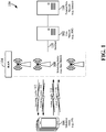
- the wireless communication system 100 may be implemented as a 5G NR network.
- the wireless communication system 100 includes three interacting domains: a core network 102, a radio access network (RAN) 104, and a user equipment (UE) 106.
- RAN radio access network
- UE user equipment
- the UE 106 may be enabled to carry out data communication with an external data network 110, such as (but not limited to) the Internet.
- the RAN 104 may implement any suitable wireless communication technology or technologies to provide radio access to the UE 106.
- the RAN 104 may operate according to 3 rd Generation Partnership Project (3GPP) New Radio (NR) specifications, often referred to as 5G.
- 3GPP 3 rd Generation Partnership Project
- NR New Radio
- the RAN 104 may operate under a hybrid of 5G NR and Evolved Universal Terrestrial Radio Access Network (eUTRAN) standards, often referred to as LTE.
- eUTRAN Evolved Universal Terrestrial Radio Access Network
- the 3GPP refers to this hybrid RAN as a next-generation RAN, or NG-RAN.
- NG-RAN next-generation RAN
- a base station is a network element in a radio access network responsible for radio transmission and reception in one or more cells to or from a UE.
- a base station may variously be referred to by those skilled in the art as a base transceiver station (BTS), a radio base station, a radio transceiver, a transceiver function, a basic service set (BSS), an extended service set (ESS), an access point (AP), a Node B (NB), an eNode B (eNB), a gNode B (gNB), or some other suitable terminology.
- BTS base transceiver station
- BSS basic service set
- ESS extended service set
- AP access point
- NB Node B
- eNB eNode B
- gNB gNode B
- the radio access network 104 is further illustrated supporting wireless communication for multiple mobile apparatuses.
- a mobile apparatus may be referred to as user equipment (UE) in 3GPP standards, but may also be referred to by those skilled in the art as a mobile station (MS), a subscriber station, a mobile unit, a subscriber unit, a wireless unit, a remote unit, a mobile device, a wireless device, a wireless communications device, a remote device, a mobile subscriber station, an access terminal (AT), a mobile terminal, a wireless terminal, a remote terminal, a handset, a terminal, a user agent, a mobile client, a client, or some other suitable terminology.
- a UE may be an apparatus that provides a user with access to network services.
- a "mobile” apparatus need not necessarily have a capability to move, and may be stationary.
- the term mobile apparatus or mobile device broadly refers to a diverse array of devices and technologies.
- UEs may include a number of hardware structural components sized, shaped, and arranged to help in communication; such components can include antennas, antenna arrays, RF chains, amplifiers, one or more processors, etc. electrically coupled to each other.
- a mobile apparatus examples include a mobile, a cellular (cell) phone, a smart phone, a session initiation protocol (SIP) phone, a laptop, a personal computer (PC), a notebook, a netbook, a smartbook, a tablet, a personal digital assistant (PDA), and a broad array of embedded systems, e.g., corresponding to an "Internet of things" (IoT).
- a cellular (cell) phone a smart phone, a session initiation protocol (SIP) phone
- laptop a personal computer
- PC personal computer
- notebook a netbook
- a smartbook a tablet
- PDA personal digital assistant
- IoT Internet of things
- a mobile apparatus may additionally be an automotive or other transportation vehicle, a remote sensor or actuator, a robot or robotics device, a satellite radio, a global positioning system (GPS) device, an object tracking device, a drone, a multi-copter, a quad-copter, a remote control device, a consumer and/or wearable device, such as eyewear, a wearable camera, a virtual reality device, a smart watch, a health or fitness tracker, a digital audio player (e.g., MP3 player), a camera, a game console, etc.
- GPS global positioning system
- a mobile apparatus may additionally be a digital home or smart home device such as a home audio, video, and/or multimedia device, an appliance, a vending machine, intelligent lighting, a home security system, a smart meter, etc.
- a mobile apparatus may additionally be a smart energy device, a security device, a solar panel or solar array, a municipal infrastructure device controlling electric power (e.g., a smart grid), lighting, water, etc.; an industrial automation and enterprise device; a logistics controller; agricultural equipment; military defense equipment, vehicles, aircraft, ships, and weaponry, etc.
- a mobile apparatus may provide for connected medicine or telemedicine support, e.g., health care at a distance.
- Telehealth devices may include telehealth monitoring devices and telehealth administration devices, whose communication may be given preferential treatment or prioritized access over other types of information, e.g., in terms of prioritized access for transport of critical service data, and/or relevant QoS for transport of critical service data.
- Wireless communication between a RAN 104 and a UE 106 may be described as utilizing an air interface.
- Transmissions over the air interface from a base station (e.g., base station 108) to one or more UEs (e.g., UE 106) may be referred to as downlink (DL) transmission.
- the term downlink may refer to a point-to-multipoint transmission originating at a scheduling entity (described further below; e.g., base station 108). Another way to describe this scheme may be to use the term broadcast channel multiplexing.
- Transmissions from a UE (e.g., UE 106) to a base station (e.g., base station 108) may be referred to as uplink (UL) transmissions.
- the term uplink may refer to a point-to-point transmission originating at a scheduled entity (described further below; e.g., UE 106).
- a scheduling entity e.g., a base station 108 allocates resources for communication among some or all devices and equipment within its service area or cell.
- the scheduling entity may be responsible for scheduling, assigning, reconfiguring, and releasing resources for one or more scheduled entities. That is, for scheduled communication, UEs 106, which may be scheduled entities, may utilize resources allocated by the scheduling entity 108.
- Base stations 108 are not the only entities that may function as scheduling entities. That is, in some examples, a UE may function as a scheduling entity, scheduling resources for one or more scheduled entities (e.g., one or more other UEs).
- a scheduling entity 108 may broadcast downlink traffic 112 to one or more scheduled entities 106.
- the scheduling entity 108 is a node or device responsible for scheduling traffic in a wireless communication network, including the downlink traffic 112 and, in some examples, uplink traffic 116 from one or more scheduled entities 106 to the scheduling entity 108.
- the scheduled entity 106 is a node or device that receives downlink control information 114, including but not limited to scheduling information (e.g., a grant), synchronization or timing information, or other control information from another entity in the wireless communication network such as the scheduling entity 108.
- base stations 108 may include a backhaul interface for communication with a backhaul portion 120 of the wireless communication system.
- the backhaul 120 may provide a link between a base station 108 and the core network 102.
- a backhaul network may provide interconnection between the respective base stations 108.
- Various types of backhaul interfaces may be employed, such as a direct physical connection, a virtual network, or the like using any suitable transport network.
- the core network 102 may be a part of the wireless communication system 100, and may be independent of the radio access technology used in the RAN 104.
- the core network 102 may be configured according to 5G standards (e.g., 5GC).
- the core network 102 may be configured according to a 4G evolved packet core (EPC), or any other suitable standard or configuration.
- 5G standards e.g., 5GC
- EPC 4G evolved packet core
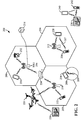
- FIG. 2 is a conceptual illustration of an example of a radio access network (RAN) 200.
- the RAN 200 may be the same as the RAN 104 described above and illustrated in FIG. 1 .
- the geographic area covered by the RAN 200 may be divided into cellular regions (cells) that can be uniquely identified by a user equipment (UE) based on an identification broadcasted from one access point or base station.
- FIG. 2 illustrates macrocells 202, 204, and 206, and a small cell 208, each of which may include one or more sectors (not shown).
- a sector is a sub-area of a cell. All sectors within one cell are served by the same base station.
- a radio link within a sector can be identified by a single logical identification belonging to that sector.
- the multiple sectors within a cell can be formed by groups of antennas with each antenna responsible for communication with UEs in a portion of the cell.
- FIG. 2 two base stations 210 and 212 are shown in cells 202 and 204; and a third base station 214 is shown controlling a remote radio head (RRH) 216 in cell 206. That is, a base station can have an integrated antenna or can be connected to an antenna or RRH by feeder cables.
- a base station can have an integrated antenna or can be connected to an antenna or RRH by feeder cables.
- the cells 202, 204, and 126 may be referred to as macrocells, as the base stations 210, 212, and 214 support cells having a large size.
- a base station 218 is shown in the small cell 208 (e.g., a microcell, picocell, femtocell, home base station, home Node B, home eNode B, etc.) which may overlap with one or more macrocells.
- the cell 208 may be referred to as a small cell, as the base station 218 supports a cell having a relatively small size. Cell sizing can be done according to system design as well as component constraints.
- the radio access network 200 may include any number of wireless base stations and cells. Further, a relay node may be deployed to extend the size or coverage area of a given cell.
- the base stations 210, 212, 214, 218 provide wireless access points to a core network for any number of mobile apparatuses. In some examples, the base stations 210, 212, 214, and/or 218 may be the same as the base station/scheduling entity 108 described above and illustrated in FIG. 1 .
- FIG. 2 further includes a quadcopter or drone 220, which may be configured to function as a base station. That is, in some examples, a cell may not necessarily be stationary, and the geographic area of the cell may move according to the location of a mobile base station such as the quadcopter 220.
- a quadcopter or drone 220 may be configured to function as a base station. That is, in some examples, a cell may not necessarily be stationary, and the geographic area of the cell may move according to the location of a mobile base station such as the quadcopter 220.
- the cells may include UEs that may be in communication with one or more sectors of each cell.
- each base station 210, 212, 214, 218, and 220 may be configured to provide an access point to a core network 102 (see FIG. 1 ) for all the UEs in the respective cells.
- UEs 222 and 224 may be in communication with base station 210; UEs 226 and 228 may be in communication with base station 212; UEs 230 and 232 may be in communication with base station 214 by way of RRH 216; UE 234 may be in communication with base station 218; and UE 236 may be in communication with mobile base station 220.
- the UEs 222, 224, 226, 228, 230, 232, 234, 236, 238, 240, and/or 242 may be the same as the UE/scheduled entity 106 described above and illustrated in FIG. 1 .
- a mobile network node e.g., quadcopter 220
- quadcopter 220 may be configured to function as a UE.
- the quadcopter 220 may operate within cell 202 by communicating with base station 210.
- sidelink signals may be used between UEs without necessarily relying on scheduling or control information from a base station.
- two or more UEs e.g., UEs 226 and 228, may communicate with each other using peer to peer (P2P) or sidelink signals 227 without relaying that communication through a base station (e.g., base station 212).
- P2P peer to peer
- UE 238 is illustrated communicating with UEs 240 and 242.
- the UE 238 may function as a scheduling entity or a primary sidelink device
- UEs 240 and 242 may function as a scheduled entity or a non-primary (e.g., secondary) sidelink device.
- a UE may function as a scheduling entity in a device-to-device (D2D), peer-to-peer (P2P), or vehicle-to-vehicle (V2V) network, and/or in a mesh network.
- D2D device-to-device
- P2P peer-to-peer
- V2V vehicle-to-vehicle
- UEs 240 and 242 may optionally communicate directly with one another in addition to communicating with the scheduling entity 238.
- a scheduling entity and one or more scheduled entities may communicate utilizing the scheduled resources.
- the ability for a UE to communicate while moving, independent of its location is referred to as mobility.
- the various physical channels between the UE and the radio access network are generally set up, maintained, and released under the control of an access and mobility management function (AMF, not illustrated, part of the core network 102 in FIG. 1 ), which may include a security context management function (SCMF) that manages the security context for both the control plane and the user plane functionality, and a security anchor function (SEAF) that performs authentication.
- AMF access and mobility management function
- SCMF security context management function
- SEAF security anchor function
- a radio access network 200 may utilize DL-based mobility or UL-based mobility to enable mobility and handovers (i.e., the transfer of a UE's connection from one radio channel to another).
- a UE may monitor various parameters of the signal from its serving cell as well as various parameters of neighboring cells. Depending on the quality of these parameters, the UE may maintain communication with one or more of the neighboring cells.
- the UE may undertake a handoff or handover from the serving cell to the neighboring (target) cell.
- UE 224 illustrated as a vehicle, although any suitable form of UE may be used
- the UE 224 may transmit a reporting message to its serving base station 210 indicating this condition.
- the UE 224 may receive a handover command, and the UE may undergo a handover to the cell 206.
- UL reference signals from each UE may be utilized by the network to select a serving cell for each UE.
- the base stations 210, 212, and 214/216 may broadcast unified synchronization signals (e.g., unified Primary Synchronization Signals (PSSs), unified Secondary Synchronization Signals (SSSs) and unified Physical Broadcast Channels (PBCH)).
- PSSs Primary Synchronization Signals
- SSSs unified Secondary Synchronization Signals
- PBCH Physical Broadcast Channels
- the UEs 222, 224, 226, 228, 230, and 232 may receive the unified synchronization signals, derive the carrier frequency and slot timing from the synchronization signals, and in response to deriving timing, transmit an uplink pilot or reference signal.
- the uplink pilot signal transmitted by a UE may be concurrently received by two or more cells (e.g., base stations 210 and 214/216) within the radio access network 200.
- Each of the cells may measure a strength of the pilot signal, and the radio access network (e.g., one or more of the base stations 210 and 214/216 and/or a central node within the core network) may determine a serving cell for the UE 224.
- the radio access network e.g., one or more of the base stations 210 and 214/216 and/or a central node within the core network
- the network may continue to monitor the uplink pilot signal transmitted by the UE 224.
- the network 200 may handover the UE 224 from the serving cell to the neighboring cell, with or without informing the UE 224.
- the synchronization signal transmitted by the base stations 210, 212, and 214/216 may be unified, the synchronization signal may not identify a particular cell, but rather may identify a zone of multiple cells operating on the same frequency and/or with the same timing.
- the use of zones in 5G networks or other next generation communication networks enables the uplink-based mobility framework and improves the efficiency of both the UE and the network, since the number of mobility messages that need to be exchanged between the UE and the network may be reduced.
- the UE may use a random access procedure to achieve UL timing synchronization with the base station.
- the UE may transmit a random access channel (RACH) preamble or request to the base station.
- RACH random access channel
- the UE may transmit the RACH request using certain RACH resources (e.g., RACH slots) allocated by the base station, for example, in a RACH configuration, which may be provided by the base station in a system information block (SIB).
- SIB system information block
- the base station sends a RACH response to the UE.
- This RACH response may include timing advance, Temporary Cell Radio Network Temporary ID (T C-RNTI), and UL grant.
- T C-RNTI Temporary Cell Radio Network Temporary ID
- the UE may synchronize its timing with the base station and start transmitting UL data using UL resources based on the UL grant.
- the air interface in the radio access network 200 may utilize licensed spectrum, unlicensed spectrum, or shared spectrum.
- Licensed spectrum provides for exclusive use of a portion of the spectrum, generally by virtue of a mobile network operator purchasing a license from a government regulatory body.
- Unlicensed spectrum provides for shared use of a portion of the spectrum without need for a government-granted license. While compliance with some technical rules is generally still required to access unlicensed spectrum, generally, any operator or device may gain access.
- Shared spectrum may fall between licensed and unlicensed spectrum, wherein technical rules or limitations may be required to access the spectrum, but the spectrum may still be shared by multiple operators and/or multiple RATs.
- the holder of a license for a portion of licensed spectrum may provide licensed shared access (LSA) to share that spectrum with other parties, e.g., with suitable licensee-determined conditions to gain access.
- LSA licensed shared access
- the air interface in the radio access network 200 may utilize one or more duplexing algorithms.
- Duplex refers to a point-to-point communication link where both endpoints can communicate with one another in both directions.
- Full duplex means both endpoints can simultaneously communicate with one another.
- Half duplex means only one endpoint can send information to the other at a time.
- a full duplex channel generally relies on physical isolation of a transmitter and receiver, and suitable interference cancellation technologies.
- Full duplex emulation is frequently implemented for wireless links by utilizing frequency division duplex (FDD) or time division duplex (TDD).
- FDD frequency division duplex
- TDD time division duplex
- transmissions in different directions on a given channel are separated from one another using time division multiplexing. That is, at some times the channel is dedicated for transmissions in one direction, while at other times the channel is dedicated for transmissions in the other direction, where the direction may change very rapidly, e.g., several times per slot.
- channel coding may be used. That is, wireless communication may generally utilize a suitable error correcting block code.
- an information message or sequence is split up into code blocks (CBs), and an encoder (e.g., a CODEC) at the transmitting device then mathematically adds redundancy to the information message. Exploitation of this redundancy in the encoded information message can improve the reliability of the message, enabling correction for any bit errors that may occur due to the noise.
- LDPC quasi-cyclic low-density parity check
- PBCH physical broadcast channel
- scheduling entities 108 and scheduled entities 106 may include suitable hardware and capabilities (e.g., an encoder, a decoder, and/or a CODEC) to utilize one or more of these channel codes for wireless communication.
- suitable hardware and capabilities e.g., an encoder, a decoder, and/or a CODEC
- the air interface in the radio access network 200 may utilize one or more multiplexing and multiple access algorithms to enable simultaneous communication of the various devices.
- 5G NR specifications provide multiple access for UL transmissions from UEs 222 and 224 to base station 210, and for multiplexing for DL transmissions from base station 210 to one or more UEs 222 and 224, utilizing orthogonal frequency division multiplexing (OFDM) with a cyclic prefix (CP).
- OFDM orthogonal frequency division multiplexing
- CP cyclic prefix
- 5G NR specifications provide support for discrete Fourier transform-spread-OFDM (DFT-s-OFDM) with a CP (also referred to as single-carrier FDMA (SC-FDMA)).
- DFT-s-OFDM discrete Fourier transform-spread-OFDM
- SC-FDMA single-carrier FDMA
- multiplexing and multiple access are not limited to the above schemes, and may be provided utilizing time division multiple access (TDMA), code division multiple access (CDMA), frequency division multiple access (FDMA), sparse code multiple access (SCMA), resource spread multiple access (RSMA), or other suitable multiple access schemes.
- multiplexing DL transmissions from the base station 210 to UEs 222 and 224 may be provided utilizing time division multiplexing (TDM), code division multiplexing (CDM), frequency division multiplexing (FDM), orthogonal frequency division multiplexing (OFDM), sparse code multiplexing (SCM), or other suitable multiplexing schemes.
- the scheduling entity and/or scheduled entity may be configured for beamforming and/or multiple-input multiple-output (MIMO) technology.
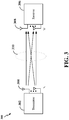
- FIG. 3 illustrates an example of a wireless communication system 300 supporting MIMO.
- a transmitter 302 includes multiple transmit antennas 304 (e.g., N transmit antennas) and a receiver 306 includes multiple receive antennas 308 (e.g., M receive antennas).
- N transmit antennas e.g., N transmit antennas
- M receive antennas e.g., M receive antennas
- Each of the transmitter 302 and the receiver 306 may be implemented, for example, within a scheduling entity 202, a scheduled entity 204, or any other suitable wireless communication device.
- Spatial multiplexing may be used to transmit different streams of data, also referred to as layers, simultaneously on the same time-frequency resource.
- the data streams may be transmitted to a single UE to increase the data rate or to multiple UEs to increase the overall system capacity, the latter being referred to as multi-user MIMO (MU-MIMO).
- MU-MIMO multi-user MIMO
- This is achieved by spatially precoding each data stream (i.e., multiplying the data streams with different weighting and phase shifting) and then transmitting each spatially precoded stream through multiple transmit antennas on the downlink.
- the spatially precoded data streams arrive at the UE(s) with different spatial signatures, which enables each of the UE(s) to recover the one or more data streams destined for that UE.
- each UE transmits a spatially precoded data stream, which enables the base station to identify the source of each spatially precoded data stream.
- the amplitude and phase of each antenna in an array of antennas may be precoded, or controlled to create a desired pattern (i.e., directional beam) of constructive and destructive interference in the wavefront.
- a frame refers to a predetermined duration (e.g., 10 ms) for wireless transmissions, with each frame consisting of a predetermined number of subframes (e.g., 10 subframes of 1 ms each).
- a predetermined duration e.g. 10 ms
- subframes e.g. 10 subframes of 1 ms each.
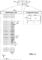
- FIG. 4 an expanded view of an exemplary DL subframe 402 is illustrated, showing an OFDM resource grid 404.
- the PHY transmission structure for any particular application may vary from the example described here, depending on any number of factors.
- time is in the horizontal direction with units of OFDM symbols; and frequency is in the vertical direction with units of subcarriers or tones.
- the resource grid 404 may be used to schematically represent time-frequency resources for a given antenna port. That is, in a MIMO implementation with multiple antenna ports available, a corresponding multiple numbers of resource grids 404 may be available for communication.
- the resource grid 404 is divided into multiple resource elements (REs) 406.
- An RE which is 1 subcarrier ⁇ 1 symbol, is the smallest discrete part of the time-frequency grid, and contains a single complex value representing data from a physical channel or signal.
- each RE may represent one or more bits of information.
- a block of REs may be referred to as a physical resource block (PRB) or more simply a resource block (RB) 408, which contains any suitable number of consecutive subcarriers in the frequency domain.
- PRB physical resource block
- RB resource block
- an RB may include 12 subcarriers, a number independent of the numerology used.
- an RB may include any suitable number of consecutive OFDM symbols in the time domain.
- a UE generally utilizes only a subset of the resource grid 404.
- An RB may be the smallest unit of resources that can be allocated to a UE.
- the RB 408 is shown as occupying less than the entire bandwidth of the subframe 402, with some subcarriers illustrated above and below the RB 408.
- the subframe 402 may have a bandwidth corresponding to any number of one or more RBs 408.
- the RB 408 is shown as occupying less than the entire duration of the subframe 402, although this is merely one possible example.
- Each 1 ms subframe 402 may consist of one or multiple adjacent slots.
- one subframe 402 includes four slots 410, as an illustrative example.
- a slot may be defined according to a specified number of OFDM symbols with a given cyclic prefix (CP) length.
- CP cyclic prefix
- a slot may include 7 or 14 OFDM symbols with a nominal CP.
- Additional examples may include mini-slots having a shorter duration (e.g., one or two OFDM symbols). These mini-slots may in some cases be transmitted occupying resources scheduled for ongoing slot transmissions for the same or for different UEs.
- An expanded view of one of the slots 410 illustrates the slot 410 including a control region 412 and a data region 414.
- the control region 412 may carry control channels (e.g., PDCCH)
- the data region 414 may carry data channels (e.g., PDSCH or PUSCH).
- a slot may contain all DL, all UL, or at least one DL portion and at least one UL portion.
- the simple structure illustrated in FIG. 4 is merely exemplary in nature, and different slot structures may be utilized, and may include one or more of each of the control region(s) and data region(s).
- the various REs 406 within a RB 408 may be scheduled to carry one or more physical channels, including control channels, shared channels, data channels, etc.
- Other REs 406 within the RB 408 may also carry pilots or reference signals, including but not limited to a demodulation reference signal (DMRS) a control reference signal (CRS), or a sounding reference signal (SRS).
- DMRS demodulation reference signal
- CRS control reference signal
- SRS sounding reference signal
- pilots or reference signals may provide for a receiving device to perform channel estimation of the corresponding channel, which may enable coherent demodulation/detection of the control and/or data channels within the RB 408.
- the transmitting device may allocate one or more REs 406 (e.g., within a control region 412) to carry DL control information 114 including one or more DL control channels, such as a PBCH; a PSS; a SSS; a physical control format indicator channel (PCFICH); a physical hybrid automatic repeat request (HARQ) indicator channel (PHICH); and/or a physical downlink control channel (PDCCH), etc., to one or more scheduled entities 106.
- the PCFICH provides information to assist a receiving device in receiving and decoding the PDCCH.
- the PDCCH carries downlink control information (DCI) including but not limited to power control commands, scheduling information, a grant, and/or an assignment of REs for DL and UL transmissions.
- DCI downlink control information
- the PHICH carries HARQ feedback transmissions such as an acknowledgment (ACK) or negative acknowledgment (NACK).
- HARQ is a technique well-known to those of ordinary skill in the art, wherein the integrity of packet transmissions may be checked at the receiving side for accuracy, e.g., utilizing any suitable integrity checking mechanism, such as a checksum or a cyclic redundancy check (CRC). If the integrity of the transmission confirmed, an ACK may be transmitted, whereas if not confirmed, a NACK may be transmitted.
- the transmitting device may send a HARQ retransmission, which may implement chase combining, incremental redundancy, etc.
- the scheduling entity may allocate certain UL resources for use in UL transmission and RACH procedure.
- the scheduling entity may indicate the allocation in DL control information.
- the transmitting device may utilize one or more REs 406 to carry UL control information 118 including one or more UL control channels, such as a physical uplink control channel (PUCCH), to the scheduling entity 108.
- UL control information may include a variety of packet types and categories, including pilots, reference signals, and information configured to enable or assist in decoding uplink data transmissions.
- the control information 118 may include a scheduling request (SR), e.g., a request for the scheduling entity 108 to schedule uplink transmissions.
- SR scheduling request
- the scheduling entity 108 may transmit downlink control information 114 that may schedule resources for uplink packet transmissions.
- UL control information may also include HARQ feedback, channel state feedback (CSF), or any other suitable UL control information.
- one or more REs 406 may be allocated for user data or traffic data. Such traffic may be carried on one or more traffic channels, such as, for a DL transmission, a physical downlink shared channel (PDSCH); or for an UL transmission, a physical uplink shared channel (PUSCH).
- PDSCH physical downlink shared channel
- PUSCH physical uplink shared channel
- one or more REs 406 within the data region 414 may be configured to carry system information blocks (SIBs), carrying information that may enable access to a given cell.
- SIBs system information blocks
- a scheduled entity may transmit uplink control information (UCI) using the PUCCH or PUSCH.
- UCI uplink control information
- UL control information include scheduling request (SR), buffer status report (BSR), HARQ ACK/NACK, CQI, etc.
- the UE may transmit other UL control information such as a beam failure indication.
- the UE may transmit the beam failure indication to indicate that a beam (e.g., a MIMO beam) or link with the base station or scheduling entity is likely to fail or has a quality less than a predetermined threshold.
- the base station may adjust the beam or initiate a handover procedure.
- the UE may transmit a beam failure indication and SR in RACH slots or non-RACH slots.
- the UE first establishes UL timing synchronization before it transmits UCI to the base station.
- the UE may perform a full random access procedure or the like to achieve UL timing synchronization (referred to as "UL sync" in this disclosure).
- UL sync UL timing synchronization
- a full random access procedure involves significant signaling overhead that increases the latency in transmitting time critical UCI (e.g., SR, BSR, beam failure indication).
- channels or carriers described above and illustrated in FIGs. 1 and 4 are not necessarily all the channels or carriers that may be utilized between a scheduling entity 108 and scheduled entities 106, and those of ordinary skill in the art will recognize that other channels or carriers may be utilized in addition to those illustrated, such as other traffic, control, and feedback channels.
- Transport channels carry blocks of information called transport blocks (TB).
- TBS transport block size
- MCS modulation and coding scheme
- a network may allocate certain UL resources that allow a UE to transmit UL data without achieving UL sync.
- the base station may allocate some resources (e.g., REs, RBs, or PRBs) in each slot or a predetermined number of slots for UCI transmission without UL sync. These resources may be referred to as sync-less UL resources or sync-less resources in this disclosure.
- the UE may transmit UCI (e.g., beam failure indication, SR, BSR) on sync-less UL resources without achieving UL sync.
- the base station may allocate the sync-less UL resources using a process similar to that used for RACH resources allocation.
- aspects of the present disclosure provide various processes and methods that enable a UE to transmit time critical UCI without first obtaining UL synchronization (UL sync) with a base station or scheduling entity.
- the base station may allocate specific network resources (e.g., UL REs) dedicated to UCI transmission without UL sync.
- the base station may allocate specific UL resources for transmitting beam failure indication, SR, and/or BSR.
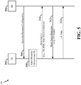
- FIG. 5 is a diagram illustrating an uplink (UL) transmission signaling diagram 500 without requiring UL synchronization between a UE 502 and a base station 504 according to some aspects of the disclosure.
- the process 500 may be carried out by the scheduling entity 108 and scheduled entity 106 illustrated in FIG. 1 .
- the UE 502 and base station 504 may correspond to the scheduled entity 106 and scheduling entity 108, respectively.
- the signaling may be carried out by any suitable apparatus or means for carrying out the functions or algorithm described below.
- the base station 504 may transmit a sync-less resource configuration 506 to the UE.
- the sync-less resource configuration 506 allocates sync-less UL resources to the UE for UL transmission.
- the resource configuration 506 may indicate certain slots and/or frequency resources (e.g., PRBs or subbands) that may be used by the UE to transmit sync-less UL control information (e.g., beam failure indication, SR, BSR) or other time critical information, with or without UL synchronization.
- the resource configuration 506 may provide a number of preambles or preamble sequences that may be used for transmitting UL data or UCI using the sync-less UL resources.
- the base station 504 may transmit the sync-less resource configuration 506 using broadcast and/or dedicated messages (e.g., SIB, DCI, RRC messages).
- broadcast and/or dedicated messages e.g., SIB, DCI, RRC messages.
- the UE transmits sync-less UL control information, it selects a preamble sequence 508 corresponding to the allocated sync-less UL resources.
- the preamble sequence 508 may be one of the preamble sequences provided in the sync-less resource configuration.
- the UE may transmit the sync-less UL control information 510 using the UL resources corresponding to the selected preamble sequence.
- the sync-less UL control information 510 may include an SR, BSR, or beam failure indication.
- the preamble sequence allows the base station to differentiate between multiple UEs transmitting sync-less UL data using the same resources in the same slot.
- the UE may determine the UL resources (e.g., sync-less resources) for transmitting the UL control information based on the resource configuration 506 received earlier from the base station 504.
- the UE 502 may store the UL data before transmission in a buffer (e.g., memory 1105 of FIG. 11 ).
- the UE may receive the UL data from a higher layer (e.g., RRC layer, MAC). Therefore, the UE may request UL resources from the base station 504 using the sync-less UCI 510 to reduce UL latency.
- the UE 502 may transmit a scheduling request (SR) in the UCI 510 in an UL control channel (e.g., PUCCH).
- SR scheduling request
- PUCCH UL control channel
- the UE 502 may transmit channel measurements to the base station with the SR or separately.
- the UE may determine the UL resources (e.g., sync-less resources) for transmitting the SR based on the resource configuration 506 received earlier from the base station 504.
- the base station 504 transmits an UL grant 512 (base station response) to the UE using a DL control channel (e.g., PDCCH).
- the UL grant may be included in a DCI or base station response dedicated to the UE.
- the UE may transmit UL data 514 using resources allocated in the UL grant.
- the UE may transmit the UL data 514 using an UL data channel (e.g., PUSCH).
- the process 500 described above is different from LTE in which a UE needs to have UL timing synchronization with a base station before the UE transmits an SR or other UCI.
- the UE may perform a full random access procedure to obtain timing synchronization with the base station.
- performing such random access procedure will add delay and increase latency to UL transmission.
- the sync-less resource configuration 506 may provide an indication that explicitly or implicitly indicates whether allocated resources (e.g., PRB or REs) can carry sync-less UL data.
- the resource configuration 506 may have specific data fields or flags that explicitly indicate whether the corresponding resources may be used for transmitting certain time critical UL control information without achieving UL sync.
- the resource configuration 506 may implicitly indicate whether allocated resources allow sync-less UCI transmission based on the type of UCI to be carried by the resource, slot, carrier, and/or resource block index. For example, it may be predetermined that certain UCI or time critical control information (e.g., SR, beam failure indication) can be transmitted without UL sync on some UL sync-less resources. In some examples, it may be predetermined that resources corresponding to certain slot indexes and/or predetermined frequency resources (e.g., PRBs or subbands) can be used to transmit sync-less UL control information. In other examples, other methods for implicitly indicating sync-less UL resources may be used.
- certain UCI or time critical control information e.g., SR, beam failure indication
- resources corresponding to certain slot indexes and/or predetermined frequency resources e.g., PRBs or subbands
- the base station may reconfigure the sync-less UL resources by sending different configurations in different slots dynamically or semi-statically.
- the base station may also configure other parameters that restrict the use of the sync-less UL resources. For example, the transmission may be allowed only if the amount of time the UE has been out of timing synchronization does not exceed a threshold.
- the sync-less resources are similar to other resources that require timing synchronization, but the criteria for being in timing synchronization are relaxed for transmission on the sync-less resources.
- FIG. 6 is a flow chart illustrating a process 600 for transmitting UL control information using sync-less resources according to some aspects of the disclosure.
- the process 600 may be carried out by the scheduled entity 106 illustrated in FIG. 1 .
- the process 600 may be carried out by any suitable apparatus or means for carrying out the functions or algorithm described below.
- a UE or scheduled entity may determine that it has UL data for transmission.
- the UE has not established UL timing synchronization with a base station (e.g., scheduling entity 108).
- a base station e.g., scheduling entity 108
- the UE needs to achieve UL synchronization with the network before the UE can transmit the UL data.
- the UE may transmit certain UL control information without first establishing UL synchronization using sync-less resources as described above.
- the UE determines whether the UL data is time critical UCI, for example, beam failure indication, SR, BSR, etc. In some examples, the UE may predetermine certain UL data to be time critical or have higher priority than other UL data. If the UL data is time critical UCI (yes branch of block 604), the process proceeds to block 606; otherwise (no branch of block 604), the process proceeds to block 608. At block 606, the UE may transmit the time critical UCI using sync-less UL resources that allow transmission of time critical UCI without UL sync. The sync-less UL resources may be allocated by the base station as described above in relation to FIG. 5 .
- the base station may allocate certain REs, PRBs, or sub-carriers in a slot for sync-less UL transmission.
- the UE For UCI that is not time critical, at block 608, the UE first obtains UL synchronization with the base station before it transmits the UL data using UL resources at block 610. For example, the UE may perform a full RACH procedure to achieve UL synchronization with the base station.
- the UE transmits a RACH request to the base station.
- the base station allocates a temporary identity (e.g., TC-RNTI) to the UE.
- the base station transmits the temporary identity to the UE as part of a RACH response.
- the RACH response may include a timing advance value so that the UE can align its UL transmission timing based on the timing advance value.
- the RACH response also provides an UL grant that allocates uplink resources to the UE for UL transmission.
- FIG. 7 is a flow chart illustrating a process 700 for allocating sync-less UL resources according to some aspects of the disclosure.
- the process 700 may be carried out by the scheduling entity 108 illustrated in FIG. 1 .
- the process 700 may be carried out by any suitable apparatus or means for carrying out the functions or algorithm described below.
- a base station may use the process 700 to allocate regular UL resources or sync-less UL resources to a UE.
- the scheduling entity may determine the quantity of UEs already allocated or assigned to certain sync-less UL resources. For example, some resources (e.g., REs in each slot) may have been allocated to sync-less UL data (e.g., UCI) and shared by a plurality of UEs.
- the scheduling entity determines whether the quantity of UEs already allocated to sync-less UL resources is greater than a predetermined threshold. In one example, the threshold may be 50% of all UEs camped in the cell or a predetermined number of UEs.
- the scheduling entity may configure a UE to use the sync-less UL resources. However, at block 710, if it is determined that the quantity of UEs already allocated to sync-less UL resources is greater than the threshold, the scheduling entity may configure the UE to use regular UL resources that need UL synchronization before the UE can transmit UL data (e.g., UCI). In some examples, the scheduling entity may transmit the scheduling information (e.g., UL grant) in a PDSCH or PDCCH.
- the scheduling information e.g., UL grant
- the scheduling entity may distinguish the UEs utilizing the same UL resources based on the different orthogonal codes (e.g., CDM codes or sequences) used by the UEs.
- the orthogonality of the codes can be maintained even when the UE transmits UL data without UL synchronization.
- the orthogonal codes may be generated by cyclic shifts of a predetermined sequence (e.g., Gold sequence).
- the scheduling entity may allocate more UEs to the same resources that require UL timing synchronization because the orthogonality of the different UL transmissions will be better maintained than that in the sync-less resources.
- FIG. 8 is a flow chart illustrating a process 800 for transmitting timing adjustments to UEs according to some aspects of the disclosure.
- the process 800 may be carried out by the scheduling entity 108 illustrated in FIG. 1 .
- the process 800 may be carried out by any suitable apparatus or means for carrying out the functions or algorithm described below.
- the scheduling entity e.g., base station, eNB, gNB
- the scheduling entity identifies a UE that transmits sync-less UL data. For example, the scheduling entity identifies the UE based on its UE ID (e.g., C-RNTI) or preamble of the UE's sync-less UL transmission.
- the scheduling entity estimates a timing adjustment based on the received sequence of the UE's sync-less UL transmission. For example, the timing adjustment may be based on the time of arrival (TOA) of the UE's signal at the scheduling entity. The TOA of the signal depends on the distance between the UE and scheduling entity.
- the scheduling entity may determine the timing adjustment so that all UE's transmissions arrive at the scheduling entity at roughly the same time, regardless of the UE's distance.
- the scheduling entity transmits the timing adjustment to the UE.
- the scheduling entity may transmit the timing adjustment in a PDCCH or DCI.
- the timing adjustment may include a plurality of bits. The value of the bits may be used by the UE to control the amount of timing adjustment that the UE has to apply.
- the timing adjustment may be a timing advance index that indicates the change of the uplink timing relative to the current uplink timing.
- the scheduling entity's response (e.g., base station response 512) to an UL transmission may or may not include a timing adjustment.
- the timing adjustment may be mandated by the network.
- the scheduling entity e.g., base station or gNB
- the scheduling entity may include the timing adjustment in the PDCCH transmission.
- the scheduling entity may include timing adjustments in its responses only for certain conditions. For example, the scheduling entity may include timing adjustments in response to UL transmission that uses sync-less UL resources.
- the scheduling entity may include timing adjustments in response to certain types of UCI (e.g., beam failure indication and SR). Further, the interpretation of the timing adjustment command may depend on the type of UCI being responded to. For example, responses to certain UCIs (such as beam failure indication) may have a larger number of bits for the timing-adjustment field, allowing for a wider range and/or a finer granularity of timing adjustment.
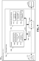
- FIG. 9 is a block diagram illustrating an example of a hardware implementation for a scheduling entity 900 employing a processing system 914.
- the scheduling entity 900 may be a user equipment (UE) as illustrated in any one or more of FIGs. 1 , 2 , 3 , and/or 5.
- the scheduling entity 900 may be a base station as illustrated in any one or more of FIGs. 1 , 2 , 3 , and/or 5.
- the scheduling entity 900 may be implemented with a processing system 914 that includes one or more processors 904.
- processors 904 include microprocessors, microcontrollers, digital signal processors (DSPs), field programmable gate arrays (FPGAs), programmable logic devices (PLDs), state machines, gated logic, discrete hardware circuits, and other suitable hardware configured to perform the various functionality described throughout this disclosure.
- the scheduling entity 900 may be configured to perform any one or more of the functions described herein. That is, the processor 904, as utilized in a scheduling entity 900, may be used to implement any one or more of the processes and procedures described and illustrated in relation to FIGs. 5-8 and 10 .
- the processing system 914 may be implemented with a bus architecture, represented generally by the bus 902.
- the bus 902 may include any number of interconnecting buses and bridges depending on the specific application of the processing system 914 and the overall design constraints.
- the bus 902 communicatively couples together various circuits including one or more processors (represented generally by the processor 904), a memory 905, and computer-readable media (represented generally by the computer-readable medium 906).
- the bus 902 may also link various other circuits such as timing sources, peripherals, voltage regulators, and power management circuits, which are well known in the art, and therefore, will not be described any further.
- a bus interface 908 provides an interface between the bus 902 and a transceiver 910.
- the transceiver 910 provides a communication interface or means for communicating with various other apparatus over a transmission medium.
- a user interface 912 e.g., keypad, display, speaker, microphone, joystick
- a user interface 912 is optional, and may be omitted in some examples, such as a base station.
- the processor 904 may include circuitry configured for various functions, including, for example, processing circuitry 940, communication circuitry 942, and resources allocation circuitry 944.
- the circuitry may be configured to implement one or more of the functions and algorithm described in relation to FIGs. 5-8 and 10 .
- the processing circuitry 940 may be configured to perform various data processing functions.
- the communication circuitry 942 may be configured to perform various communication functions including decoding, encoding, modulation, demodulation, mapping, demapping, multiplexing, demultiplexing, interleaving, de-interleaving, error correction, transmitting and receiving signal via the transceiver 910, etc.
- the resources allocation circuitry 944 may be configured to allocate communication resources to UEs. For example, the resources allocation circuitry 944 may allocate sync-less UL resources to UEs for transmitting certain UL data without first achieving UL synchronization.
- the processor 904 is responsible for managing the bus 902 and general processing, including the execution of software stored on the computer-readable medium 906.
- the software when executed by the processor 904, causes the processing system 914 to perform the various functions described below for any particular apparatus.
- the computer-readable medium 906 and the memory 905 may also be used for storing data that is manipulated by the processor 904 when executing software.
- One or more processors 904 in the processing system may execute software.
- Software shall be construed broadly to mean instructions, instruction sets, code, code segments, program code, programs, subprograms, software modules, applications, software applications, software packages, routines, subroutines, objects, executables, threads of execution, procedures, functions, etc., whether referred to as software, firmware, middleware, microcode, hardware description language, or otherwise.
- the software may reside on a computer-readable medium 906.
- the computer-readable medium 906 may be a non-transitory computer-readable medium.
- a non-transitory computer-readable medium includes, by way of example, a magnetic storage device (e.g., hard disk, floppy disk, magnetic strip), an optical disk (e.g., a compact disc (CD) or a digital versatile disc (DVD)), a smart card, a flash memory device (e.g., a card, a stick, or a key drive), a random access memory (RAM), a read only memory (ROM), a programmable ROM (PROM), an erasable PROM (EPROM), an electrically erasable PROM (EEPROM), a register, a removable disk, and any other suitable medium for storing software and/or instructions that may be accessed and read by a computer.
- a magnetic storage device e.g., hard disk, floppy disk, magnetic strip
- an optical disk e.g., a compact disc (CD) or a digital versatile disc (DVD)
- a smart card e.g., a flash memory device (e.g.
- the computer-readable medium 906 may reside in the processing system 914, external to the processing system 914, or distributed across multiple entities including the processing system 914.
- the computer-readable medium 906 may be embodied in a computer program product.
- a computer program product may include a computer-readable medium in packaging materials.
- the computer-readable storage medium 906 may include software configured for various functions, including, for example, processing instructions 952, communication instructions 954, and resources allocation instructions 956.
- the software may be configured to implement one or more of the functions described in relation to FIGs. 5-8 and 10 .
- the processing instructions 952 may be configured to perform various data processing functions.
- the communication instructions 954 may be configured to perform various communication functions including decoding, encoding, modulation, demodulation, mapping, demapping, multiplexing, demultiplexing, interleaving, de-interleaving, error correction, transmitting and receiving signal via the transceiver 910, etc.
- the resources allocation instructions 956 may be configured to allocate communication resources to UEs. For example, the resources allocation instructions 956 may allocate sync-less UL resources to UEs for transmitting certain UL data without first achieving UL synchronization.
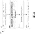
- FIG. 10 is a flow chart illustrating an exemplary process 1000 for receiving uplink control information without UL timing synchronization in accordance with some aspects of the present disclosure.
- the process 1000 may be carried out by the scheduling entities illustrated in FIGs. 1-3 , 5 , and 9 .
- the process 1000 may be carried out by any suitable apparatus or means for carrying out the functions or algorithm described below.
- the scheduling entity 900 may use the communication circuitry 942 and transceiver 910 to transmit an allocation of resources (e.g., RBs) for sync-less UL transmission to a UE.
- resources e.g., RBs
- the scheduling entity may transmit the sync-less resource allocation using broadcast and/or dedicated messages (e.g., SIB, DCI, RRC messages).
- SIB SIB, DCI, RRC messages.
- the sync-less UL transmission may be the same as that described above in relation to FIGs. 5-8 .
- the scheduling entity may use its communication circuitry 942 and transceiver 910 to receive UCI from the UE.
- the UCI is transmitted using the sync-less UL resources allocated to UL transmissions regardless of UL timing synchronization between the UE and the scheduling entity.
- the UCI may include beam failure indication, scheduling request (SR), and/or buffer status report (BSR).
- SR scheduling request
- BSR buffer status report
- the scheduling entity may use its communication circuitry 942 and transceiver 910 to transmit a base station response to the UE. For example, if the UCI includes an SR or BSR, the base station response may provide an UL grant. The scheduling entity may use its resources allocation circuitry 944 to determine the UL grant that allocates certain resources for UL transmission. If the UCI includes a beam failure indication, the scheduling entity may transit a beam reference signal on one or more new beams. Then, at block 1008, the scheduling entity may optionally use its communication circuitry 942 and transceiver 910 to receive UL data from the UE based on the base station response (e.g., UL grant).
- the base station response e.g., UL grant
- the scheduling entity may receive UL data utilizing UL resources scheduled by the UL grant. This process can reduce the latency in receiving the UL data because the UE does not need to go through a full random access procedure to obtain UL timing synchronization before transmitting the UCI (e.g., SR).
- UCI e.g., SR
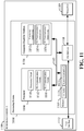
- FIG. 11 is a conceptual diagram illustrating an example of a hardware implementation for an exemplary scheduled entity 1100 employing a processing system 1114.
- an element, or any portion of an element, or any combination of elements may be implemented with a processing system 1114 that includes one or more processors 1104.
- the scheduled entity 1100 may be a user equipment (UE) as illustrated in any one or more of FIGs. 1 , 2 , 3 , and/or 5.
- UE user equipment
- the processing system 1114 may be substantially the same as the processing system 914 illustrated in FIG. 9 , including a bus interface 1108, a bus 1102, memory 1105, a processor 1104, and a computer-readable medium 1106.
- the memory may store UL data in an UL buffer 1120 and sync-less preambles 1122 for transmitting UL data.
- the scheduled entity 1100 may include a user interface 1112 and a transceiver 1110 substantially similar to those described above in FIG. 9 . That is, the processor 1104, as utilized in a scheduled entity 1100, may be used to implement any one or more of the processes described and illustrated in FIGs. 5-8 and 12 .
- the processor 1104 may include circuitry configured for various functions, including, for example, processing circuitry 1140, UL communication circuitry 1142, and DL communication circuitry 1144.
- the circuitry may be configured to implement one or more of the functions described below in relation to FIG. 12 .
- the computer-readable storage medium 1106 may include software configured for various functions, including, for example, processing instructions 1152, UL communication instructions 1154, and DL communication instructions 1156.
- the software may be configured to implement one or more of the functions described in relation to FIGs. 5-8 and 12 .
- the processing circuitry 1140 may be configured to perform various data processing functions.
- the UL communication circuitry 1142 may be configured to perform various UL communication functions including encoding, modulation, mapping, multiplexing, interleaving, error correction encoding, transmitting signal via the transceiver 1110, etc.
- the DL communication circuitry 1144 may be configured to perform various DL communication functions including decoding, demodulation, demapping, demultiplexing, de-interleaving, error correction decoding, receiving signal via the transceiver 1110, etc.
- the processing instructions 1152 may be configured to perform various data processing functions.
- the UL communication instructions 1154 may be configured to perform various UL communication functions including encoding, modulation, mapping, multiplexing, interleaving, error correction encoding, transmitting signal via the transceiver 1110, etc.
- the DL communication instructions 1156 may be configured to perform various DL communication functions including decoding, demodulation, demapping, demultiplexing, de-interleaving, error correction decoding, receiving signal via the transceiver 1110, etc.
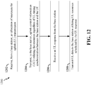
- FIG. 12 is a flow chart illustrating an exemplary process 1200 for transmitting uplink control information without UL timing synchronization in accordance with some aspects of the present disclosure.
- some or all illustrated features may be omitted in a particular implementation within the scope of the present disclosure, and some illustrated features may not be required for implementation of all embodiments.
- the process 1200 may be carried out by any of the scheduled entities illustrated in FIGs. 1-3 , 5 , and 11 .
- the process 1200 may be carried out by any suitable apparatus or means for carrying out the functions or algorithm described below.
- a scheduled entity 1100 may use its DL communication circuitry 1144 and transceiver 1110 to receive an allocation of resources for UL transmission from a base station or scheduling entity.
- the scheduled entity may receive the resource allocation in a broadcast and/or dedicated message (e.g., SIB, DCI, and RRC messages). At least some of the allocated resources may be used for sync-less UL transmission.
- the scheduled entity may receive a sync-less resource configuration (e.g., configuration 506 of FIG. 5 ) that indicates the sync-less UL resources.
- the sync-less resource configuration may provide a number of preambles that may be used for transmitting UL data or UCI using the sync-less UL resources.
- the preambles may be stored in the memory 1105 of the scheduled entity.
- the scheduled entity may use its UL communication circuitry 1142 and transceiver 1110 to transmit uplink control information (UCI) utilizing the resources (e.g., sync-less resources) allocated to UL transmissions regardless of UL timing synchronization between the base station and UE.
- the resources may include some REs in a slot allocated to UCI transmissions that are time critical.
- the scheduled entity transmits UCI using the sync-less UL resources, the scheduled entity needs not perform UL timing synchronization with the base station before transmitting such UCI.
- the UCI may include an SR or beam failure indication.
- the scheduled entity may use its DL communication circuit 1144 and transceiver 1110 to receive a base station response (e.g., UL grant) from the base station.
- a base station response e.g., UL grant
- the UL grant may be received in a DCI of a PDCCH or PDSCH.
- the base station response from the base station may include a beam reference signal.
- the scheduled entity may use the UL communication circuitry 1142 and transceiver 1110 to optionally transmit UL data to the base station utilizing UL resources scheduled by the base station response.
- the UL data may be queued in an UL buffer in the memory 1105 (see FIG. 11 ) before transmission. This process can reduce the latency in transmitting the UL data because the scheduled entity does not go through a full random access procedure to obtain UL timing synchronization before transmitting the UCI.
- the apparatus 900 and/or 1100 for wireless communication includes means for performing sync-less UL transmission as described above.
- the aforementioned means may be the processor(s) 904/1104 in which the invention resides shown in FIG. 9 / 11 configured to perform the functions recited by the aforementioned means.
- the aforementioned means may be a circuit or any apparatus configured to perform the functions recited by the aforementioned means.
- circuitry included in the processor 904/1104 is merely provided as an example, and other means for carrying out the described functions may be included within various aspects of the present disclosure, including but not limited to the instructions stored in the computer-readable storage medium 906/1106, or any other suitable apparatus or means described in any one of the FIGs. 1 , 2 , 3 , and/or 5, and utilizing, for example, the processes and/or algorithms described herein in relation to FIGs. 5-8 , 10 , and 12 .
- various aspects may be implemented within other systems defined by 3GPP, such as Long-Term Evolution (LTE), the Evolved Packet System (EPS), the Universal Mobile Telecommunication System (UMTS), and/or the Global System for Mobile (GSM).
- LTE Long-Term Evolution
- EPS Evolved Packet System
- UMTS Universal Mobile Telecommunication System
- GSM Global System for Mobile
- 3GPP2 3rd Generation Partnership Project 2
- EV-DO Evolution-Data Optimized
- Other examples may be implemented within systems employing IEEE 802.11 (Wi-Fi), IEEE 802.16 (WiMAX), IEEE 802.20, Ultra-Wideband (UWB), Bluetooth, and/or other suitable systems.
- Wi-Fi IEEE 802.11
- WiMAX IEEE 802.16
- UWB Ultra-Wideband
- Bluetooth and/or other suitable systems.
- the actual telecommunication standard, network architecture, and/or communication standard employed will depend on the specific application and the overall design constraints imposed on the system.
- the word "exemplary” is used to mean “serving as an example, instance, or illustration.” Any implementation or aspect described herein as “exemplary” is not necessarily to be construed as preferred or advantageous over other aspects of the disclosure. Likewise, the term “aspects” does not require that all aspects of the disclosure include the discussed feature, advantage or mode of operation.
- the term “coupled” is used herein to refer to the direct or indirect coupling between two objects. For example, if object A physically touches object B, and object B touches object C, then objects A and C may still be considered coupled to one another-even if they do not directly physically touch each other. For instance, a first object may be coupled to a second object even though the first object is never directly physically in contact with the second object.
- circuit and circuitry are used broadly, and intended to include both hardware implementations of electrical devices and conductors that, when connected and configured, enable the performance of the functions described in the present disclosure, without limitation as to the type of electronic circuits, as well as software implementations of information and instructions that, when executed by a processor, enable the performance of the functions described in the present disclosure.
- FIGs. 1-12 One or more of the components, steps, features and/or functions illustrated in FIGs. 1-12 may be rearranged and/or combined into a single component, step, feature or function or embodied in several components, steps, or functions. Additional elements, components, steps, and/or functions may also be added without departing from novel features disclosed herein.
- the apparatus, devices, and/or components illustrated in FIGs. 1-12 may be configured to perform one or more of the methods, features, or steps described herein.
- the novel algorithms described herein may also be efficiently implemented in software and/or embedded in hardware.
Landscapes
- Engineering & Computer Science (AREA)
- Computer Networks & Wireless Communication (AREA)
- Signal Processing (AREA)
- Mobile Radio Communication Systems (AREA)
Claims (14)
- Procédé (1200) pour une communication sans fil mis en œuvre au niveau d'un équipement d'utilisateur UE (502), comprenant :une réception (1202), à partir d'une station de base (504), d'une configuration de ressources (506) qui attribue des ressources pour une transmission de liaison montante, UL, sans synchronisation ;une transmission (1204), vers la station de base, d'informations de commande de liaison montante, UCI (510), en utilisant les ressources indépendamment d'une synchronisation de temporisation d'UL entre la station de base et l'UE ;une réception (1206) d'un octroi d'UL (512) correspondant aux UCI à partir de la station de base ; etune transmission (1208) de données d'UL (514) vers la station de base sur la base de l'octroi d'UL.
- Procédé selon la revendication 1, dans lequel les UCI comprennent des informations urgentes incluant au moins un élément parmi :une indication de défaillance de faisceau ;une demande de planification ; ouun rapport d'état de tampon.
- Procédé selon la revendication 1, dans lequel la configuration de ressources comprend un ou plusieurs préambules configurés pour une transmission des UCI en utilisant les ressources pour une transmission UL sans synchronisation.
- Procédé selon la revendication 3, dans lequel la transmission des UCI comprend :une sélection d'un préambule des un ou plusieurs préambules ; etune transmission des UCI en utilisant des ressources d'UL sans synchronisation correspondant au préambule.
- Procédé selon la revendication 1, dans lequel la configuration de ressources indique explicitement que les ressources sont attribuées pour être utilisées pour transmettre les UCI indépendamment d'une synchronisation de temporisation d'UL.
- Procédé selon la revendication 1, dans lequel la configuration de ressources indique implicitement que les ressources sont attribuées pour être utilisées pour transmettre les UCI indépendamment d'une synchronisation de temporisation d'UL.
- Procédé selon la revendication 6, dans lequel la configuration de ressources indique implicitement les ressources sur la base d'au moins un élément parmi un type d'UCI, un créneau, une porteuse, ou un indice de bloc de ressources.
- Procédé selon la revendication 1, dans lequel la réception de l'octroi d'UL comprend :
une réception d'une réponse de canal d'accès aléatoire, RACH, qui inclut l'octroi d'UL et inclut un ajustement de temporisation pour des transmissions UL subséquentes. - Procédé (1000) pour une communication sans fil mis en œuvre au niveau d'une station de base (504), comprenant :une transmission (1002), vers un équipement d'utilisateur, UE (502), d'une configuration de ressources (506) qui attribue des ressources pour une transmission de liaison montante, UL, sans synchronisation ;une réception (1004), à partir de l'UE, d'informations de commande de liaison montante, UCI (510), en utilisant les ressources indépendamment d'une synchronisation de temporisation d'UL entre l'UE et la station de base ;une transmission (1006) d'un octroi d'UL (512) correspondant aux UCI vers l'UE ; etune réception (1008) de données d'UL (514) à partir de l'UE sur la base de l'octroi d'UL.
- Procédé selon la revendication 9, dans lequel la configuration de ressources comprend un ou plusieurs préambules configurés pour une transmission des UCI en utilisant les ressources pour une transmission UL sans synchronisation.
- Procédé selon la revendication 10, dans lequel la réception des UCI comprend :
une réception des UCI en utilisant des ressources correspondant à un des un ou plusieurs préambules. - Procédé selon la revendication 9, comprenant en outre :
une configuration de l'UE pour transmettre les UCI en utilisant les ressources pour une transmission UL sans synchronisation si une quantité d'UE attribuée aux ressources est inférieure à un seuil prédéterminé. - Station de base configurée pour une communication sans fil, comprenant :une interface de communication configurée pour communiquer avec un équipement d'utilisateur, UE ;une mémoire ; etun processeur couplé de manière fonctionnelle avec l'interface de communication et la mémoire, dans lequel le processeur et la mémoire sont configurés pour :une transmission, vers l'UE, d'une configuration de ressources qui attribue des ressources pour une transmission de liaison montante, UL, sans synchronisation ;une réception, à partir de l'UE, d'informations de commande de liaison montante, UCI, en utilisant les ressources indépendamment d'une synchronisation de temporisation d'UL entre l'UE et la station de base ;une transmission d'un octroi d'UL correspondant aux UCI vers l'UE ; etune réception de données d'UL à partir de l'UE sur la base de l'octroi d'UL.
- Équipement d'utilisateur, UE, configuré pour une communication sans fil, comprenant :une interface de communication configurée pour communiquer avec une station de base ;une mémoire ; etun processeur couplé de manière fonctionnelle avec l'interface de communication et la mémoire, dans lequel le processeur et la mémoire sont configurés pour :une réception, à partir d'une station de base, d'une configuration de ressources qui attribue des ressources pour une transmission de liaison montante, UL, sans synchronisation ;une transmission, vers la station de base, d'informations de commande de liaison montante, UCI, en utilisant les ressources indépendamment d'une synchronisation de temporisation d'UL entre la station de base et l'UE ;une réception d'un octroi d'UL correspondant aux UCI à partir de la station de base ; etune transmission de données d'UL à la station de base sur la base de l'octroi d'UL.
Applications Claiming Priority (3)
| Application Number | Priority Date | Filing Date | Title |
|---|---|---|---|
| US201762502394P | 2017-05-05 | 2017-05-05 | |
| US15/969,281 US11228992B2 (en) | 2017-05-05 | 2018-05-02 | Uplink transmissions without timing synchronization in wireless communication |
| PCT/US2018/030984 WO2018204718A1 (fr) | 2017-05-05 | 2018-05-03 | Transmissions de liaison montante sans synchronisation temporelle dans une communication sans fil |
Publications (2)
| Publication Number | Publication Date |
|---|---|
| EP3619980A1 EP3619980A1 (fr) | 2020-03-11 |
| EP3619980B1 true EP3619980B1 (fr) | 2022-01-12 |
Family
ID=64015118
Family Applications (1)
| Application Number | Title | Priority Date | Filing Date |
|---|---|---|---|
| EP18726660.6A Active EP3619980B1 (fr) | 2017-05-05 | 2018-05-03 | Transmissions de liaison montante sans synchronisation temporelle dans une communication sans fil |
Country Status (5)
| Country | Link |
|---|---|
| US (1) | US11228992B2 (fr) |
| EP (1) | EP3619980B1 (fr) |
| CN (1) | CN110583055B (fr) |
| TW (1) | TWI762630B (fr) |
| WO (1) | WO2018204718A1 (fr) |
Families Citing this family (23)
| Publication number | Priority date | Publication date | Assignee | Title |
|---|---|---|---|---|
| US11337265B2 (en) | 2017-08-10 | 2022-05-17 | Comcast Cable Communications, Llc | Beam failure recovery request transmission |
| US10887939B2 (en) | 2017-08-10 | 2021-01-05 | Comcast Cable Communications, Llc | Transmission power control for beam failure recovery requests |
| US11950287B2 (en) | 2017-08-10 | 2024-04-02 | Comcast Cable Communications, Llc | Resource configuration of beam failure recovery request transmission |
| US10855359B2 (en) | 2017-08-10 | 2020-12-01 | Comcast Cable Communications, Llc | Priority of beam failure recovery request and uplink channels |
| US11277301B2 (en) | 2017-09-07 | 2022-03-15 | Comcast Cable Communications, Llc | Unified downlink control information for beam management |
| US11611468B2 (en) | 2017-09-28 | 2023-03-21 | Comcast Cable Communications, Llc | Beam management with DRX configuration |
| CA3024596A1 (fr) | 2017-11-16 | 2019-05-16 | Comcast Cable Communications, Llc | Assistance d'appel de faisceau |
| US10863570B2 (en) | 2018-01-09 | 2020-12-08 | Comcast Cable Communications, Llc | Beam selection in beam failure recovery request retransmission |
| EP3525516B1 (fr) | 2018-02-09 | 2022-08-31 | Comcast Cable Communications, LLC | Procédure de récupération d'échec de faisceau dans une agrégation de porteuses |
| US11419066B2 (en) | 2018-02-15 | 2022-08-16 | Comcast Cable Communications, Llc | Beam failure report |
| CA3038605A1 (fr) | 2018-03-30 | 2019-09-30 | Comcast Cable Communications, Llc | Configuration de recuperation de defaillance de faisceau |
| WO2019191753A1 (fr) | 2018-03-30 | 2019-10-03 | Ofinno, Llc | Rétablissement après une défaillance de faisceau fondée sur une demande de planification |
| US11039350B2 (en) | 2018-04-02 | 2021-06-15 | Comcast Cable Communications, Llc | Beam failure recovery |
| US11095355B2 (en) | 2018-05-10 | 2021-08-17 | Comcast Cable Communications, Llc | Prioritization in beam failure recovery procedures |
| US11012137B2 (en) | 2018-08-09 | 2021-05-18 | Comcast Cable Communications, Llc | Resource management for beam failure recovery procedures |
| CA3056500A1 (fr) | 2018-09-24 | 2020-03-24 | Comcast Cable Communications, Llc | Procedures de reprise apres une defaillance de faisceau |
| EP3629492A1 (fr) | 2018-09-25 | 2020-04-01 | Comcast Cable Communications LLC | Configuration de faisceau pour des cellules secondaires |
| JP7297079B2 (ja) * | 2019-02-15 | 2023-06-23 | テレフオンアクチーボラゲット エルエム エリクソン(パブル) | アップリンク送信に関連する方法、装置、およびコンピュータ可読媒体 |
| WO2020171744A1 (fr) * | 2019-02-18 | 2020-08-27 | Telefonaktiebolaget Lm Ericsson (Publ) | Procédés et unités d'un système de station de base pour transmission sur des liens fronthaul |
| EP4005316A4 (fr) | 2019-07-26 | 2023-08-23 | Fg Innovation Company Limited | Procédés et appareils de planification de priorisation de ressources de demande pour une reprise sur défaillance de faisceau |
| EP3799518A1 (fr) * | 2019-09-27 | 2021-03-31 | Apple Inc. | Transmission d'une requête de récupération d'une liaison de cellules secondaires |
| CN112584443A (zh) * | 2019-09-27 | 2021-03-30 | 苹果公司 | 辅助小区链路恢复请求传输 |
| US11924801B2 (en) | 2020-05-15 | 2024-03-05 | Qualcomm Incorporated | Determining factors for splitting positioning state information (PSI) between uplink control information (UCI) and medium access control control elements (MAC-CE) |
Family Cites Families (18)
| Publication number | Priority date | Publication date | Assignee | Title |
|---|---|---|---|---|
| US20030119452A1 (en) * | 2001-10-19 | 2003-06-26 | Samsung Electronics Co., Ltd. | Apparatus and method for controlling transmission power of downlink data channel in a mobile communication system supporting MBMS |
| KR101211807B1 (ko) * | 2006-01-05 | 2012-12-12 | 엘지전자 주식회사 | 이동통신 시스템에서 무선단말의 동기상태 관리방법 |
| ES2617745T3 (es) | 2006-02-07 | 2017-06-19 | Nokia Technologies Oy | Aparato, método y producto de programa informático que proporcionan sincronización rápida y fiable de enlace ascendente usando recursos dedicados para equipos de usuario que necesitan sincronización |
| PL2034755T3 (pl) | 2006-06-01 | 2013-06-28 | Huawei Tech Co Ltd | Sposób łączenia stacji ruchomej ze stacja bazową |
| US8295243B2 (en) * | 2006-08-21 | 2012-10-23 | Qualcomm Incorporated | Method and apparatus for random access in an orthogonal multiple-access communication system |
| CN103228038B (zh) | 2008-06-02 | 2017-02-15 | 富士通株式会社 | 定时调节方法、移动站、基站以及移动通信系统 |
| CN101674661B (zh) | 2009-10-14 | 2011-12-07 | 普天信息技术研究院有限公司 | 长期演进系统中的随机接入方法 |
| US9497714B2 (en) | 2010-09-24 | 2016-11-15 | Qualcomm Incorporated | Power control for a network of access points |
| WO2012091645A1 (fr) * | 2010-12-30 | 2012-07-05 | Telefonaktiebolaget L M Ericsson (Publ) | Procédé et configuration destinés à adapter un temps de garde sur la base d'une avance de temps |
| US9363820B2 (en) * | 2011-08-11 | 2016-06-07 | Industrial Technology Research Institute | Method of uplink control information transmission |
| GB2519456B (en) * | 2013-01-15 | 2017-05-31 | Zte Wistron Telecom Ab | Operation of a heterogeneous wireless network by determining location of a wireless device |
| US9949275B2 (en) | 2013-10-01 | 2018-04-17 | Qualcomm Incorporated | Physical uplink control management in LTE/LTE-A systems with unlicensed spectrum |
| WO2015122701A1 (fr) * | 2014-02-16 | 2015-08-20 | Lg Electronics Inc. | Procédé et appareil pour transmettre des données de liaison montante dans un système de communication sans fil |
| US10250362B2 (en) * | 2014-03-20 | 2019-04-02 | Interdigital Patent Holdings, Inc. | Method and apparatus for non-orthogonal access in LTE systems |
| US10349433B2 (en) | 2015-04-28 | 2019-07-09 | Lg Electronics Inc. | Method for receiving a MAC CE for contention-based PUSCH in a wireless communication system and a device therefor |
| US10327232B2 (en) | 2015-09-02 | 2019-06-18 | Qualcomm Incorporated | Techniques for allocating time and frequency resources to an uplink channel to carry uplink control information used for narrowband communication |
| JP6404256B2 (ja) * | 2016-04-14 | 2018-10-10 | 株式会社Nttドコモ | ユーザ端末及び無線通信方法 |
| JP7034906B2 (ja) * | 2016-05-06 | 2022-03-14 | 株式会社Nttドコモ | 端末、無線通信方法、基地局及びシステム |
-
2018
- 2018-05-02 US US15/969,281 patent/US11228992B2/en active Active
- 2018-05-03 TW TW107115035A patent/TWI762630B/zh active
- 2018-05-03 EP EP18726660.6A patent/EP3619980B1/fr active Active
- 2018-05-03 CN CN201880028941.2A patent/CN110583055B/zh active Active
- 2018-05-03 WO PCT/US2018/030984 patent/WO2018204718A1/fr active Application Filing
Also Published As
| Publication number | Publication date |
|---|---|
| CN110583055B (zh) | 2021-10-01 |
| TWI762630B (zh) | 2022-05-01 |
| WO2018204718A1 (fr) | 2018-11-08 |
| US20180324723A1 (en) | 2018-11-08 |
| CN110583055A (zh) | 2019-12-17 |
| EP3619980A1 (fr) | 2020-03-11 |
| US11228992B2 (en) | 2022-01-18 |
| TW201843971A (zh) | 2018-12-16 |
Similar Documents
| Publication | Publication Date | Title |
|---|---|---|
| EP3619980B1 (fr) | Transmissions de liaison montante sans synchronisation temporelle dans une communication sans fil | |
| US11425720B2 (en) | System and method for transmitting beam failure recovery request | |
| EP3847858B1 (fr) | Techniques pour la détermination d'un état de configuration d'une transmission | |
| EP3711249B1 (fr) | Sélection d'une ressource de liaison montante en nouvelle radio de façon à transmettre une communication d'une procédure d'accès aléatoire | |
| US11240774B2 (en) | Timing advance group for new radio | |
| US10651995B2 (en) | Transmission of group common control information in new radio | |
| US11743889B2 (en) | Channel state information (CSI) reference signal (RS) configuration with cross-component carrier CSI prediction algorithm | |
| US11323227B2 (en) | Multiplexing of physical uplink shared channel (PUSCH) and physical uplink control channel (PUCCH) in uplink short burst transmission | |
| EP3782294B1 (fr) | Procédé et appareil d'indication d'une transmission commune de points de transmission multiples dans un nouveau système radio | |
| EP3711208B1 (fr) | Procédé et appareil de détermination de taille de bloc de transport dans un système de communication sans fil | |
| US11552753B2 (en) | Enablement of simultaneous beam update across component carriers | |
| WO2021253213A1 (fr) | Procédé et appareil de communication sans fil utilisant différentes capacités de dispositif pour canal de commande et canal de données |
Legal Events
| Date | Code | Title | Description |
|---|---|---|---|
| STAA | Information on the status of an ep patent application or granted ep patent |
Free format text: STATUS: UNKNOWN |
|
| STAA | Information on the status of an ep patent application or granted ep patent |
Free format text: STATUS: THE INTERNATIONAL PUBLICATION HAS BEEN MADE |
|
| PUAI | Public reference made under article 153(3) epc to a published international application that has entered the european phase |
Free format text: ORIGINAL CODE: 0009012 |
|
| STAA | Information on the status of an ep patent application or granted ep patent |
Free format text: STATUS: REQUEST FOR EXAMINATION WAS MADE |
|
| 17P | Request for examination filed |
Effective date: 20191015 |
|
| AK | Designated contracting states |
Kind code of ref document: A1 Designated state(s): AL AT BE BG CH CY CZ DE DK EE ES FI FR GB GR HR HU IE IS IT LI LT LU LV MC MK MT NL NO PL PT RO RS SE SI SK SM TR |
|
| AX | Request for extension of the european patent |
Extension state: BA ME |
|
| DAV | Request for validation of the european patent (deleted) | ||
| DAX | Request for extension of the european patent (deleted) | ||
| GRAP | Despatch of communication of intention to grant a patent |
Free format text: ORIGINAL CODE: EPIDOSNIGR1 |
|
| STAA | Information on the status of an ep patent application or granted ep patent |
Free format text: STATUS: GRANT OF PATENT IS INTENDED |
|
| INTG | Intention to grant announced |
Effective date: 20210723 |
|
| GRAS | Grant fee paid |
Free format text: ORIGINAL CODE: EPIDOSNIGR3 |
|
| GRAA | (expected) grant |
Free format text: ORIGINAL CODE: 0009210 |
|
| STAA | Information on the status of an ep patent application or granted ep patent |
Free format text: STATUS: THE PATENT HAS BEEN GRANTED |
|
| AK | Designated contracting states |
Kind code of ref document: B1 Designated state(s): AL AT BE BG CH CY CZ DE DK EE ES FI FR GB GR HR HU IE IS IT LI LT LU LV MC MK MT NL NO PL PT RO RS SE SI SK SM TR |
|
| REG | Reference to a national code |
Ref country code: GB Ref legal event code: FG4D |
|
| REG | Reference to a national code |
Ref country code: CH Ref legal event code: EP |
|
| REG | Reference to a national code |
Ref country code: DE Ref legal event code: R096 Ref document number: 602018029510 Country of ref document: DE |
|
| REG | Reference to a national code |
Ref country code: IE Ref legal event code: FG4D |
|
| REG | Reference to a national code |
Ref country code: AT Ref legal event code: REF Ref document number: 1463189 Country of ref document: AT Kind code of ref document: T Effective date: 20220215 |
|
| REG | Reference to a national code |
Ref country code: LT Ref legal event code: MG9D |
|
| REG | Reference to a national code |
Ref country code: NL Ref legal event code: MP Effective date: 20220112 |
|
| REG | Reference to a national code |
Ref country code: AT Ref legal event code: MK05 Ref document number: 1463189 Country of ref document: AT Kind code of ref document: T Effective date: 20220112 |
|
| PG25 | Lapsed in a contracting state [announced via postgrant information from national office to epo] |
Ref country code: NL Free format text: LAPSE BECAUSE OF FAILURE TO SUBMIT A TRANSLATION OF THE DESCRIPTION OR TO PAY THE FEE WITHIN THE PRESCRIBED TIME-LIMIT Effective date: 20220112 |
|
| PG25 | Lapsed in a contracting state [announced via postgrant information from national office to epo] |
Ref country code: SE Free format text: LAPSE BECAUSE OF FAILURE TO SUBMIT A TRANSLATION OF THE DESCRIPTION OR TO PAY THE FEE WITHIN THE PRESCRIBED TIME-LIMIT Effective date: 20220112 Ref country code: RS Free format text: LAPSE BECAUSE OF FAILURE TO SUBMIT A TRANSLATION OF THE DESCRIPTION OR TO PAY THE FEE WITHIN THE PRESCRIBED TIME-LIMIT Effective date: 20220112 Ref country code: PT Free format text: LAPSE BECAUSE OF FAILURE TO SUBMIT A TRANSLATION OF THE DESCRIPTION OR TO PAY THE FEE WITHIN THE PRESCRIBED TIME-LIMIT Effective date: 20220512 Ref country code: NO Free format text: LAPSE BECAUSE OF FAILURE TO SUBMIT A TRANSLATION OF THE DESCRIPTION OR TO PAY THE FEE WITHIN THE PRESCRIBED TIME-LIMIT Effective date: 20220412 Ref country code: LT Free format text: LAPSE BECAUSE OF FAILURE TO SUBMIT A TRANSLATION OF THE DESCRIPTION OR TO PAY THE FEE WITHIN THE PRESCRIBED TIME-LIMIT Effective date: 20220112 Ref country code: HR Free format text: LAPSE BECAUSE OF FAILURE TO SUBMIT A TRANSLATION OF THE DESCRIPTION OR TO PAY THE FEE WITHIN THE PRESCRIBED TIME-LIMIT Effective date: 20220112 Ref country code: ES Free format text: LAPSE BECAUSE OF FAILURE TO SUBMIT A TRANSLATION OF THE DESCRIPTION OR TO PAY THE FEE WITHIN THE PRESCRIBED TIME-LIMIT Effective date: 20220112 Ref country code: BG Free format text: LAPSE BECAUSE OF FAILURE TO SUBMIT A TRANSLATION OF THE DESCRIPTION OR TO PAY THE FEE WITHIN THE PRESCRIBED TIME-LIMIT Effective date: 20220412 |
|
| PG25 | Lapsed in a contracting state [announced via postgrant information from national office to epo] |
Ref country code: PL Free format text: LAPSE BECAUSE OF FAILURE TO SUBMIT A TRANSLATION OF THE DESCRIPTION OR TO PAY THE FEE WITHIN THE PRESCRIBED TIME-LIMIT Effective date: 20220112 Ref country code: LV Free format text: LAPSE BECAUSE OF FAILURE TO SUBMIT A TRANSLATION OF THE DESCRIPTION OR TO PAY THE FEE WITHIN THE PRESCRIBED TIME-LIMIT Effective date: 20220112 Ref country code: GR Free format text: LAPSE BECAUSE OF FAILURE TO SUBMIT A TRANSLATION OF THE DESCRIPTION OR TO PAY THE FEE WITHIN THE PRESCRIBED TIME-LIMIT Effective date: 20220413 Ref country code: FI Free format text: LAPSE BECAUSE OF FAILURE TO SUBMIT A TRANSLATION OF THE DESCRIPTION OR TO PAY THE FEE WITHIN THE PRESCRIBED TIME-LIMIT Effective date: 20220112 Ref country code: AT Free format text: LAPSE BECAUSE OF FAILURE TO SUBMIT A TRANSLATION OF THE DESCRIPTION OR TO PAY THE FEE WITHIN THE PRESCRIBED TIME-LIMIT Effective date: 20220112 |
|
| PG25 | Lapsed in a contracting state [announced via postgrant information from national office to epo] |
Ref country code: IS Free format text: LAPSE BECAUSE OF FAILURE TO SUBMIT A TRANSLATION OF THE DESCRIPTION OR TO PAY THE FEE WITHIN THE PRESCRIBED TIME-LIMIT Effective date: 20220512 |
|
| REG | Reference to a national code |
Ref country code: DE Ref legal event code: R097 Ref document number: 602018029510 Country of ref document: DE |
|
| PG25 | Lapsed in a contracting state [announced via postgrant information from national office to epo] |
Ref country code: SM Free format text: LAPSE BECAUSE OF FAILURE TO SUBMIT A TRANSLATION OF THE DESCRIPTION OR TO PAY THE FEE WITHIN THE PRESCRIBED TIME-LIMIT Effective date: 20220112 Ref country code: SK Free format text: LAPSE BECAUSE OF FAILURE TO SUBMIT A TRANSLATION OF THE DESCRIPTION OR TO PAY THE FEE WITHIN THE PRESCRIBED TIME-LIMIT Effective date: 20220112 Ref country code: RO Free format text: LAPSE BECAUSE OF FAILURE TO SUBMIT A TRANSLATION OF THE DESCRIPTION OR TO PAY THE FEE WITHIN THE PRESCRIBED TIME-LIMIT Effective date: 20220112 Ref country code: EE Free format text: LAPSE BECAUSE OF FAILURE TO SUBMIT A TRANSLATION OF THE DESCRIPTION OR TO PAY THE FEE WITHIN THE PRESCRIBED TIME-LIMIT Effective date: 20220112 Ref country code: DK Free format text: LAPSE BECAUSE OF FAILURE TO SUBMIT A TRANSLATION OF THE DESCRIPTION OR TO PAY THE FEE WITHIN THE PRESCRIBED TIME-LIMIT Effective date: 20220112 Ref country code: CZ Free format text: LAPSE BECAUSE OF FAILURE TO SUBMIT A TRANSLATION OF THE DESCRIPTION OR TO PAY THE FEE WITHIN THE PRESCRIBED TIME-LIMIT Effective date: 20220112 |
|
| PLBE | No opposition filed within time limit |
Free format text: ORIGINAL CODE: 0009261 |
|
| STAA | Information on the status of an ep patent application or granted ep patent |
Free format text: STATUS: NO OPPOSITION FILED WITHIN TIME LIMIT |
|
| PG25 | Lapsed in a contracting state [announced via postgrant information from national office to epo] |
Ref country code: AL Free format text: LAPSE BECAUSE OF FAILURE TO SUBMIT A TRANSLATION OF THE DESCRIPTION OR TO PAY THE FEE WITHIN THE PRESCRIBED TIME-LIMIT Effective date: 20220112 |
|
| 26N | No opposition filed |
Effective date: 20221013 |
|
| REG | Reference to a national code |
Ref country code: CH Ref legal event code: PL |
|
| REG | Reference to a national code |
Ref country code: BE Ref legal event code: MM Effective date: 20220531 |
|
| PG25 | Lapsed in a contracting state [announced via postgrant information from national office to epo] |
Ref country code: MC Free format text: LAPSE BECAUSE OF FAILURE TO SUBMIT A TRANSLATION OF THE DESCRIPTION OR TO PAY THE FEE WITHIN THE PRESCRIBED TIME-LIMIT Effective date: 20220112 Ref country code: LU Free format text: LAPSE BECAUSE OF NON-PAYMENT OF DUE FEES Effective date: 20220503 Ref country code: LI Free format text: LAPSE BECAUSE OF NON-PAYMENT OF DUE FEES Effective date: 20220531 Ref country code: CH Free format text: LAPSE BECAUSE OF NON-PAYMENT OF DUE FEES Effective date: 20220531 |
|
| PG25 | Lapsed in a contracting state [announced via postgrant information from national office to epo] |
Ref country code: SI Free format text: LAPSE BECAUSE OF FAILURE TO SUBMIT A TRANSLATION OF THE DESCRIPTION OR TO PAY THE FEE WITHIN THE PRESCRIBED TIME-LIMIT Effective date: 20220112 |
|
| PG25 | Lapsed in a contracting state [announced via postgrant information from national office to epo] |
Ref country code: IE Free format text: LAPSE BECAUSE OF NON-PAYMENT OF DUE FEES Effective date: 20220503 |
|
| PGFP | Annual fee paid to national office [announced via postgrant information from national office to epo] |
Ref country code: FR Payment date: 20230223 Year of fee payment: 6 |
|
| PG25 | Lapsed in a contracting state [announced via postgrant information from national office to epo] |
Ref country code: BE Free format text: LAPSE BECAUSE OF NON-PAYMENT OF DUE FEES Effective date: 20220531 |
|
| PG25 | Lapsed in a contracting state [announced via postgrant information from national office to epo] |
Ref country code: IT Free format text: LAPSE BECAUSE OF FAILURE TO SUBMIT A TRANSLATION OF THE DESCRIPTION OR TO PAY THE FEE WITHIN THE PRESCRIBED TIME-LIMIT Effective date: 20220112 |
|
| PGFP | Annual fee paid to national office [announced via postgrant information from national office to epo] |
Ref country code: DE Payment date: 20230223 Year of fee payment: 6 |
|
| PGFP | Annual fee paid to national office [announced via postgrant information from national office to epo] |
Ref country code: GB Payment date: 20230412 Year of fee payment: 6 |
|
| PG25 | Lapsed in a contracting state [announced via postgrant information from national office to epo] |
Ref country code: MK Free format text: LAPSE BECAUSE OF FAILURE TO SUBMIT A TRANSLATION OF THE DESCRIPTION OR TO PAY THE FEE WITHIN THE PRESCRIBED TIME-LIMIT Effective date: 20220112 Ref country code: CY Free format text: LAPSE BECAUSE OF FAILURE TO SUBMIT A TRANSLATION OF THE DESCRIPTION OR TO PAY THE FEE WITHIN THE PRESCRIBED TIME-LIMIT Effective date: 20220112 |