EP3619765B1 - Device for manipulating membranes - Google Patents
Device for manipulating membranes Download PDFInfo
- Publication number
- EP3619765B1 EP3619765B1 EP18728926.9A EP18728926A EP3619765B1 EP 3619765 B1 EP3619765 B1 EP 3619765B1 EP 18728926 A EP18728926 A EP 18728926A EP 3619765 B1 EP3619765 B1 EP 3619765B1
- Authority
- EP
- European Patent Office
- Prior art keywords
- membrane
- station
- membranes
- manipulator
- magazine
- Prior art date
- Legal status (The legal status is an assumption and is not a legal conclusion. Google has not performed a legal analysis and makes no representation as to the accuracy of the status listed.)
- Active
Links
- 239000012528 membrane Substances 0.000 title claims description 221
- 238000003860 storage Methods 0.000 claims description 55
- 239000000446 fuel Substances 0.000 claims description 9
- 238000013016 damping Methods 0.000 claims description 5
- 239000005518 polymer electrolyte Substances 0.000 description 27
- 230000002787 reinforcement Effects 0.000 description 23
- 230000003014 reinforcing effect Effects 0.000 description 22
- 238000010438 heat treatment Methods 0.000 description 21
- 238000009434 installation Methods 0.000 description 20
- 238000003825 pressing Methods 0.000 description 13
- 239000010410 layer Substances 0.000 description 12
- 238000005520 cutting process Methods 0.000 description 7
- 238000009792 diffusion process Methods 0.000 description 6
- 229910052751 metal Inorganic materials 0.000 description 6
- 239000002184 metal Substances 0.000 description 6
- 230000002093 peripheral effect Effects 0.000 description 5
- 238000001816 cooling Methods 0.000 description 4
- 238000006073 displacement reaction Methods 0.000 description 4
- 238000005304 joining Methods 0.000 description 4
- 238000000429 assembly Methods 0.000 description 3
- 230000000712 assembly Effects 0.000 description 3
- 239000003054 catalyst Substances 0.000 description 2
- 230000003197 catalytic effect Effects 0.000 description 2
- 230000006835 compression Effects 0.000 description 2
- 238000007906 compression Methods 0.000 description 2
- 239000007789 gas Substances 0.000 description 2
- 239000011229 interlayer Substances 0.000 description 2
- 238000002955 isolation Methods 0.000 description 2
- 238000004519 manufacturing process Methods 0.000 description 2
- 238000000034 method Methods 0.000 description 2
- BASFCYQUMIYNBI-UHFFFAOYSA-N platinum Chemical compound [Pt] BASFCYQUMIYNBI-UHFFFAOYSA-N 0.000 description 2
- 239000002699 waste material Substances 0.000 description 2
- 229920000049 Carbon (fiber) Polymers 0.000 description 1
- 239000011230 binding agent Substances 0.000 description 1
- 230000015572 biosynthetic process Effects 0.000 description 1
- 239000002826 coolant Substances 0.000 description 1
- 239000000110 cooling liquid Substances 0.000 description 1
- 238000000151 deposition Methods 0.000 description 1
- 239000003792 electrolyte Substances 0.000 description 1
- 238000000605 extraction Methods 0.000 description 1
- 239000003517 fume Substances 0.000 description 1
- 230000012447 hatching Effects 0.000 description 1
- 238000012423 maintenance Methods 0.000 description 1
- VNWKTOKETHGBQD-UHFFFAOYSA-N methane Chemical compound C VNWKTOKETHGBQD-UHFFFAOYSA-N 0.000 description 1
- 229910052697 platinum Inorganic materials 0.000 description 1
- 230000003068 static effect Effects 0.000 description 1
- 230000003685 thermal hair damage Effects 0.000 description 1
- 238000003466 welding Methods 0.000 description 1
Images


Classifications
-
- H—ELECTRICITY
- H01—ELECTRIC ELEMENTS
- H01M—PROCESSES OR MEANS, e.g. BATTERIES, FOR THE DIRECT CONVERSION OF CHEMICAL ENERGY INTO ELECTRICAL ENERGY
- H01M8/00—Fuel cells; Manufacture thereof
- H01M8/24—Grouping of fuel cells, e.g. stacking of fuel cells
- H01M8/2404—Processes or apparatus for grouping fuel cells
-
- H—ELECTRICITY
- H01—ELECTRIC ELEMENTS
- H01M—PROCESSES OR MEANS, e.g. BATTERIES, FOR THE DIRECT CONVERSION OF CHEMICAL ENERGY INTO ELECTRICAL ENERGY
- H01M8/00—Fuel cells; Manufacture thereof
- H01M8/02—Details
- H01M8/0271—Sealing or supporting means around electrodes, matrices or membranes
- H01M8/0273—Sealing or supporting means around electrodes, matrices or membranes with sealing or supporting means in the form of a frame
-
- H—ELECTRICITY
- H01—ELECTRIC ELEMENTS
- H01M—PROCESSES OR MEANS, e.g. BATTERIES, FOR THE DIRECT CONVERSION OF CHEMICAL ENERGY INTO ELECTRICAL ENERGY
- H01M8/00—Fuel cells; Manufacture thereof
- H01M8/24—Grouping of fuel cells, e.g. stacking of fuel cells
- H01M8/241—Grouping of fuel cells, e.g. stacking of fuel cells with solid or matrix-supported electrolytes
- H01M8/2418—Grouping by arranging unit cells in a plane
-
- Y—GENERAL TAGGING OF NEW TECHNOLOGICAL DEVELOPMENTS; GENERAL TAGGING OF CROSS-SECTIONAL TECHNOLOGIES SPANNING OVER SEVERAL SECTIONS OF THE IPC; TECHNICAL SUBJECTS COVERED BY FORMER USPC CROSS-REFERENCE ART COLLECTIONS [XRACs] AND DIGESTS
- Y02—TECHNOLOGIES OR APPLICATIONS FOR MITIGATION OR ADAPTATION AGAINST CLIMATE CHANGE
- Y02E—REDUCTION OF GREENHOUSE GAS [GHG] EMISSIONS, RELATED TO ENERGY GENERATION, TRANSMISSION OR DISTRIBUTION
- Y02E60/00—Enabling technologies; Technologies with a potential or indirect contribution to GHG emissions mitigation
- Y02E60/30—Hydrogen technology
- Y02E60/50—Fuel cells
Definitions
- the present invention relates to the field of membrane/electrode assembly devices for fuel cells.
- Proton exchange membrane fuel cells called PEMFC corresponding to the English acronym for “proton exchange membrane fuel cells” or “polymer electrolyte membrane fuel cells”, have particularly advantageous compactness properties.
- Each cell comprises a polymer electrolyte membrane allowing only the passage of protons and not the passage of electrons.
- the membrane is brought into contact with an anode on a first face and with a cathode on a second face to form a membrane/electrode assembly called MEA.
- the aforementioned assembly is generally made by successive superposition of the various membranes and electrodes with an interposition of reinforcing membranes making it possible to support the assembly.
- the gripping by a manipulator arm of easily deformable membranes can prove to be difficult to achieve and is all the more so as the thickness of the membranes of an AME assembly is of the order of a hundred micrometers.
- the gripping by a manipulator of the upper membrane on a stack of membranes proves to be very difficult to achieve since the mechanical connection made at the moment of gripping the membrane is a rigid connection which can induce strong mechanical stresses. on the arm to ensure good contact with the membrane to be gripped.
- JP 2007 287436 A discloses a membrane handling device, in particular for a fuel cell, comprising a membrane storage station and means for conveying and manipulating a membrane from the storage station to a receiving station, the conveying means and manipulation comprise means of gripping with suction and the membrane storage station comprises a store for stacking the membranes.
- the present invention relates first of all to a device for handling membranes for a fuel cell comprising a membrane storage station and means for conveying and manipulating a membrane from the storage station to a reception station, characterized in that the conveying and handling means comprise suction gripping means and in that the membrane storage station comprises a membrane stack storage magazine which is guided for movement in a given direction on a fixed frame bearing means for damping and returning the store to a predetermined position in the absence of pressing force exerted on the store in said direction by the suction gripping means.
- the mechanical connection produced is not completely static since a movement of the store for storing and supporting the membranes can take place in the given direction which is preferably a vertical direction corresponding to a stacking direction of the membranes in the store.
- the suction gripping means comprise a frame comprising a plurality of orifices opening onto a flat gripping face of the frame, these orifices being connected to the means for supplying a vacuum.
- the conveying and handling means may comprise a manipulator comprising a connecting segment of two rotation joints, one of which carries the suction gripping means.
- the damping and return means comprise a lever whose pivot point carried by a fixed frame separates a counterweight on one side and on the other side a rigid connecting rod to the magazine which is oriented according to said direction.
- the frame comprises a fixed plate comprising an opening in which the connecting rod is guided to move in said direction and in that the plate is inserted in said direction between the magazine and the lever.
- the device may comprise auxiliary guide means for movement in said direction of the magazine on the plate.
- Each electrode membrane 12, 20 comprises a first layer and a second layer distinct from each other.
- the first layer is a diffusion layer formed of a carbon fabric on which is deposited the second catalytic layer comprising a binder incorporating a catalyst such as platinum.
- the second catalytic layer is arranged in contact with the polymer electrolyte membrane 16.
- the polymer electrolyte membrane 16 is completely housed between the first 14 and second 18 reinforcing membranes and thus achieves an isolation of the polymer electrolyte membrane from the coolant and pure gas passages.
- This type of mounting is known as “anti-wicking”.
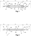
- the assembly presented in figure 1 comprises a peripheral cutout 22 with a closed contour forming an external contour of the assembly 10 electrolyte membrane - electrodes - reinforcement membranes.
- the assembly 10 also comprises orifices 24 between said peripheral cutout 22 and the outer edge 16a of the polymer electrolyte membrane 16, these orifices 24 being intended for the passage of cooling liquid and pure gases (H 2 and O 2 ).
- these orifices 24 are formed in a peripheral zone surrounding the polymer electrolyte membrane 16 and the first 12 and second 20 electrodes.
- FIG 2 represents a second assembly 11 that can be produced with the installation described below.
- the stacking of the different membranes is identical to what has been described with reference to the picture 1 .
- the assembly shown in this figure does not perform an “anti-wicking” function, that is to say in which the polymer electrolyte membrane is not confined between the first 14 and second 18 membrane reinforcements as explained in reference to the figure 1 but extends everywhere between the first reinforcing membrane 14 and the second reinforcing membrane 18.
- the polymer electrolyte membrane 16 differs from the assembly 10 described with reference to the picture 1 .
- FIG. 8 represents an installation according to the invention, the figure 8 being a graphical representation of the installation shown in figures 3 to 7 .
- the various units of the installation will now be described one after the other and positioned relative to each other according to three perpendicular directions of space two by two perpendicular, namely two horizontal directions, one of which is a longitudinal direction. L and the other a transverse direction T, and a vertical direction Z.
- the conveying and handling means comprise a plurality of manipulators five in number in the embodiment shown in the figures.
- Each manipulator comprises means for taking up and placing a membrane or a plurality of membranes integral with each other.
- a first manipulator B 1 is configured to allow movement of an electrode membrane from the first storage station A 1 to the stacking station C.
- a second manipulator B 2 is configured to allow movement of a reinforcement membrane 14 , 18 from the second storage station A 2 to the stacking station C.
- a third manipulator B 3 is configured to allow movement of a support membrane from the third storage station A 3 to the pressing station P and heating.
- a fourth manipulator B 4 is configured to allow movement of an interleaving sheet from the first storage station A 1 to the fourth storage station of interleaving sheets.
- a fifth manipulator B 5 is configured to allow movement of a final assembly from the cutting station D to the fifth station A 5 for storing the assemblies 10, 11 and the displacement of the membrane waste from the cutting station D to the sixth storage station A 6 .
- the installation 1 also comprises means E for securing a stack made at the level of the stacking station C.
- the pressing and heating station P comprises two presses P 1 , P 2 arranged side by side in the longitudinal direction.
- the presses P 1 and P 2 each comprise a piston P 1a , P 2a arranged to move in the vertical direction opposite a press support P 1b , P 2b , the pistons and press support being carried by a frame P 1c , press P 2c .
- the first press P 1 makes it possible to ensure controlled pressing, heating and cooling of the lower electrode stack zone Z 1 - polymer electrolyte membrane - upper electrode, this zone Z 1 being represented on the figures 1 and 2 .
- This zone Z 1 comprises all of the electrodes and preferably only these.
- the second press P 2 makes it possible to ensure controlled pressing, heating and cooling of a zone Z 2 of stack of membranes which is annular and surrounds the electrodes.
- This zone Z 2 being represented on the figures 1 and 2 .
- This zone Z 1 comprises all of the electrodes and preferably only these.
- the frame P 1c of the press P 1 carries means for securing the membranes comprising in the present case heating punches P 1d intended to be applied to the membranes.
- the stacking station C is arranged longitudinally between the first storage station A 1 and the second storage station A 2 .
- the pressing and heating station P is here arranged in the transverse direction T between the stacking station C and a longitudinal rail 33 allowing the longitudinal displacement of the third manipulator B 3 .
- the pressing and heating station P is arranged longitudinally between the cutting station D and the third storage station A 3 , the latter station A 3 being arranged transversely opposite the second storage station A 2 . Also, the stacking station C is inserted longitudinally between the first storage station A 1 and the second storage station A 2 .
- the station E for cutting an assembly 10, 11 as described with reference to the figures 1 and 2 may comprise laser means confined inside a fume extraction hood generated by the peripheral cutout 22 and the orifices 24.
- FIGS. 6 to 8 represent a schematic perspective view of the stacking station C , of the first storage station A 1 , of the second storage station A 2 and of the fourth storage station A 4 .
- the stacking station C comprises a tray C 1 comprising an opening C 2 having more precisely the shape of a U-shaped notch, the function of which will appear clearly later in the description given in relation to the figures 21 to 24 showing the production of a first stack according to the invention.
- FIGS 6 to 8 are thus clearly visible the first manipulator B 1 , the second manipulator B 2 as well as the fourth manipulator B 4 .
- THE figures 9 and 10 represent in isolation the stacking station C comprising the stacking plate C 1 and the securing means E.
- the plate C 1 and said securing means E are carried by a fixed frame 30 .
- the securing means E comprise heating punches E 1 , for example four, allowing the welding of the membranes stacked on the stacking station C , these securing means E are carried by a base 32 secured to a slider 34 movable in translation relative to the support frame 30 facing the stacking tray C 1 .
- the heating punches E 1 are moved until they come into contact with the stack of membranes positioned on the stacking station C. It is understood that the punches E 1 carry out a support and a heating of the stack on the plate C1 .
- connection is made between a reinforcing membrane 14, 18 and an electrode membrane 12, 20. In practice, this is made on the immediate periphery of the opening 14a, 18a of a reinforcing membrane 14, 18, preferably at of the four corners of the opening 14a, 18a which has a rectangular shape.
- THE figures 11 and 12 represent the first storage station A 1 for electrode membranes 12, 20 and the first manipulator B 1 for electrode membranes 12, 20.
- the first storage station A 1 comprises a store 36 for stacking electrode membranes 12, 20 comprising a plate 38 intended to receive a stack of membrane electrodes 12, 20.
- the edge of plate 38 is provided with means 40 for positioning the membrane electrodes in a predetermined position. These positioning means 40 are formed by flanges positioned in the format of the electrodes 12, 20.
- the magazine 36 of electrodes 12, 20 is guided for movement in a given vertical direction Z on a fixed frame 42 carrying damping and recall 44 of the store in a predetermined position in the absence of pressing force exerted on the store in said direction by the first manipulator B 1 .
- a vertical connecting rod 46 rigidly connects at its upper end the plate 38 of the magazine 36 and is hinged in rotation at its lower end to a first end 48 of a lever 50 whose second end 52 opposite carries a counterweight 54
- the first end 48 and the second end 52 of the lever 50 are separated by a pivot 55 integral with a fixed plate 42.
- the connecting rod 46 passes through the fixed plate 36 and is guided in vertical translation in an opening thereof.
- the fixed plate 42 is interposed between the magazine 36 and the lever 50.
- the magazine 36 is also connected to the fixed plate 42 by additional means 56 for guiding the magazine in vertical translation, making it possible to compensate for the guiding errors in vertical translation resulting from the sliding of the rod 46 in the opening of the fixed plate 42 .
- the first manipulator arm B1 advantageously comprises a first joint 58 and a second joint 60 for rotation connected to each other by a connecting segment 62 .
- the two joints 58, 60 are here articulated in rotation along axes parallel to each other and extending in a transverse direction T.
- the first joint 58 is mounted on the frame 64 of the installation and on a first end of the segment 62 so as to articulate them relatively to one another around a first axis of rotation.
- the second joint 58 is mounted on the second end of the segment and on one end of a support 66 elongated in a direction parallel to the axes of rotation and carrying means for taking up and placing a membrane.
- These gripping and laying means 68 comprise suction gripping means advantageously comprising, in the case of the first station, suction cups aligned in a transverse direction T and connected to means for supplying a vacuum.
- the first manipulator B 1 is able to move between a position for picking up an electrode membrane 12, 20 in the electrode magazine 36 and a position for laying an electrode membrane 12, 20 on the platform of the station. stack C.
- a laying position corresponds to a position in which the membrane electrode 12, 20 is arranged in contact with the plate C 1 or another membrane as will appear later, the gripping means 68 being held at the active state in order to guarantee maintenance of the electrode.
- the first manipulator B 1 comprises a first laying position and a second laying position of an electrode membrane 12, 20 on the plate C 1 of the stacking station C.
- the first manipulator B 1 moves a membrane electrode 12 from the first storage station A 1 to the plate C 1 of the stacking station C without turning over the electrode membrane 12.
- the first manipulator B 1 performs a second movement of a membrane electrode 20 from the first storage station A 1 to the plate C 1 of the stacking station C with a reversal of the electrode membrane 20.
- the elongated support 66 of the suction cups is housed in the notch C 2 of the stacking tray C 1 as shown in figure 22 and as will appear more clearly in relation to the description of the operation of the installation carried out with reference to the figures 21 to 27 .
- this type of movement of the first manipulator B 1 allows a simple stacking of the electrode membranes 12, 20 in the same way in the first storage station A 1 , with their first face oriented upwards so that it serves as the face of gripping while allowing orientation of the second face carrying the catalyst downwards or upwards at the level of the stacking station.
- FIG 13 represents the fourth manipulator B 4 comprising a segment 70 bearing at one end means 72 for gripping and laying an insert sheet, these means also comprising suction cups 72 connected to means for supplying a depression.
- the segment 70 of the fourth manipulator B 4 is rotatably articulated at its end opposite the suction cups 72 on a support 74 movable in translation vertically with respect to the frame 76 of the installation.
- the fourth manipulator B 4 thus allows in operation a gripping of an interlayer sheet and its supply to the fourth storage station A 4 of interlayer membranes.
- FIG 14 represents the second storage station A 2 for reinforcement membranes 14, 18 which is in all respects similar to the first storage station A 1 described with reference to figure 11 . It will not be described again.
- the second manipulator B 2 visible in figure 15 , also comprises two joints 58, 60 in rotation having axes parallel to one to the other. Unlike the first manipulator B 1 , the second manipulator B 2 comprises a means 78 for translation movement such as a sliding rail in the transverse direction. Also, the second rotational joint 60 carries gripping and laying means comprising suction gripping means which are, in the present case, formed of a rigid frame 80 comprising a flat gripping face comprising a plurality of perforations connected to means for providing a vacuum.
- the second manipulator B 2 is configured to perform a displacement movement of a membrane or of a set of several membranes integral with each other from the second station A 2 onto the plate C 1 of the stacking station C without turning over the membrane or said set of membranes.
- THE figures 16 and 17 represent the third manipulator B 3 comprising a transverse translation rail 82 itself mounted in translation on the longitudinal rail 33 .
- the transverse rail 82 carrying a vertical rail 84 integral with a support 85 extending in the transverse direction.
- the support 85 of the third arm B 3 carries magnetic gripping and laying means 86 comprising electromagnets actuated by control means of the installation. These gripping and laying means are able to pick up a metal frame from the third storage station A3 to bring it under the first press P 1 .
- the fifth manipulator B 5 is shown in figure 5 and comprises gripping and laying means comprising suction gripping means and magnetic gripping means allowing the movement of a metal frame, in order to allow storage of the polymer electrolyte membrane - electrode assemblies at the level of the fifth storage station and metal frames at the sixth post.
- the installation 1 according to the invention is advantageously usable so as to allow the production of an assembly 10 in accordance with the figure 1 or an assembly 11 in accordance with picture 2 , depending on how the second and third stations are supplied.
- the first manipulator B 1 is actuated so as to grip a first electrode 12 by its diffusion layer and then to perform positioning of the first manipulator arm B 1 in its first laying position on the stacking station C , the second layer of the first electrode 12 facing upwards.
- the second manipulator B 2 moves a first reinforcement membrane 14 alone from the second storage station A 2 to the stacking station C so that the opening 14a of the first reinforcement membrane 14 is closed lowerly by the first electrode 12.
- the first electrode membrane 12 and the first reinforcement membrane 14 are secured using the securing means E arranged at the level of the stacking station C.
- the suction gripping means of the first arm B 1 and of the second manipulator B 2 are kept active during the securing step so that each membrane is secured to its manipulator.
- the assembly thus formed is moved from the stacking station C onto the press support P 1b , using the second manipulator B 2 , the suction gripping means of the first manipulator B 1 being rendered inactive while the suction gripping means of the second manipulator B 2 are kept in the active state so as to allow the movement of the assembly of the two membranes.
- a support membrane 26 enclosed in a metal frame 28 is brought, by means of the third manipulator B 3 , over the assembly formed by the first electrode 12 and the first reinforcement membrane 14, the internal edge 26b of the support membrane 26 being applied to the outer edge 14c of the first reinforcing membrane 14.
- a sample is taken using the second manipulator B 2 of a set of a second reinforcing membrane 18 and a polymer electrolyte membrane 16, these membranes 16, 18 having been fastened together beforehand.
- This assembly is moved on the plate C 1 of the stacking station C in a seventh step and a second electrode 20 is brought, in an eighth step, from the first storage station A 1 to the stacking station C at the using the first manipulator B 1 so that it closes off the opening 18a of the second reinforcement 18 from above, the first manipulator B 1 being in its second laying position.
- the suction gripping means of the first arm B 1 and of the second manipulator B 2 are kept active during the joining step.
- the second electrode membrane 20 and the second reinforcement membrane 18 are secured using the securing means E arranged at the level of the stacking station C.
- This step is carried out using the second manipulator B 2 , the suction gripping means of the first manipulator B 1 being made inactive while the suction gripping means of the second manipulator B 2 are maintained in the active state so to allow the movement of all the membranes.
- the assembly thus formed is shown in figures 25 and 26 .
- an operation of controlled pressing, heating and cooling of zone Z 1 (represented in dotted hatching on the figure 26 ) in order to secure the electrode membranes 12, 20 with the reinforcement membranes 14, 18 and avoid any relative movement of the membranes with respect to each other.
- the eleventh step of compression and heating of the electrodes can be followed by a step of joining the reinforcement membranes 14, 18 by the heating punches P 1d for example in a plurality of locations 88, for example four, located at the periphery of the membranes reinforcements 14, 18 ( figures 25 and 26 ).
- This step can also be initiated at the end of the compression and heating cycle and finish simultaneously or after it.
- the joining step by heating punches P 1d precedes the step of heating and compressing the annular zone Z 2 .
- This securing step prevents the lower reinforcing membrane 14 from buckling and folding back on itself leading to the formation of a double thickness of reinforcing membrane 14 resulting in the assembly 10 being scrapped for non-compliance.
- the third manipulator B 3 moves the assembly 10 on the support P 2b of the press P 2 and a controlled pressing, heating and cooling operation is performed on the zone Z 2 (shown in hatched lines full on the figure 26 )
- the assembly is moved to the level of the cutting station in order to produce the peripheral edge 22 and the orifices 24 , then the assemblies 10 are collected at the level of the fifth station A 5 and the metal frames 28 as well as remnants of membranes at the level of the sixth post A 6 .
- the installation comprises control means for the conveying and handling means, these control means being configured so that the departure of a stack from the stacking station C to the pressing and heating station P is followed by a new stacking step on the stacking station C.
Landscapes
- Chemical Kinetics & Catalysis (AREA)
- Engineering & Computer Science (AREA)
- Manufacturing & Machinery (AREA)
- Sustainable Development (AREA)
- Sustainable Energy (AREA)
- Chemical & Material Sciences (AREA)
- Life Sciences & Earth Sciences (AREA)
- Electrochemistry (AREA)
- General Chemical & Material Sciences (AREA)
- Fuel Cell (AREA)
- Separation Using Semi-Permeable Membranes (AREA)
- Specific Conveyance Elements (AREA)
- Sheets, Magazines, And Separation Thereof (AREA)
Description
La présente invention concerne le domaine des dispositifs d'assemblage membrane / électrodes pour pile à combustible.The present invention relates to the field of membrane/electrode assembly devices for fuel cells.
Les piles à combustible à membrane d'échange de protons, dites PEMFC correspondant à l'acronyme anglais de « proton exchange membrane fuel cells » ou « polymer electrolyte membrane fuel cells », présentent des propriétés de compacité particulièrement intéressantes. Chaque cellule comprend une membrane électrolyte polymère permettant seulement le passage de protons et non le passage des électrons. La membrane est mise en contact avec une anode sur une première face et avec une cathode sur une deuxième face pour former un assemblage membrane/électrodes dit AME.Proton exchange membrane fuel cells, called PEMFC corresponding to the English acronym for “proton exchange membrane fuel cells” or “polymer electrolyte membrane fuel cells”, have particularly advantageous compactness properties. Each cell comprises a polymer electrolyte membrane allowing only the passage of protons and not the passage of electrons. The membrane is brought into contact with an anode on a first face and with a cathode on a second face to form a membrane/electrode assembly called MEA.
L'assemblage précité est généralement réalisé par superposition successive des différentes membranes et électrodes avec une interposition de membranes de renfort permettant de supporter l'assemblage. Toutefois, la préhension par un bras de manipulateur de membranes aisément déformables peut s'avérer difficile à réaliser et l'est d'autant plus que l'épaisseur des membranes d'un assemblage AME est de l'ordre de la centaine de micromètres. De plus, la préhension par un manipulateur de la membrane supérieure sur un empilement de membranes s'avère très difficile à réaliser puisque la liaison mécanique réalisée à l'instant de la préhension de la membrane est une liaison rigide qui peut induire des contraintes mécaniques fortes sur le bras pour assurer un bon contact avec la membrane à saisir.The aforementioned assembly is generally made by successive superposition of the various membranes and electrodes with an interposition of reinforcing membranes making it possible to support the assembly. However, the gripping by a manipulator arm of easily deformable membranes can prove to be difficult to achieve and is all the more so as the thickness of the membranes of an AME assembly is of the order of a hundred micrometers. In addition, the gripping by a manipulator of the upper membrane on a stack of membranes proves to be very difficult to achieve since the mechanical connection made at the moment of gripping the membrane is a rigid connection which can induce strong mechanical stresses. on the arm to ensure good contact with the membrane to be gripped.
La présente invention concerne tout d'abord un dispositif de manipulation de membranes pour pile à combustible comprenant un poste de stockage de membranes et des moyens de convoyage et de manipulation d'une membrane depuis le poste de stockage jusque vers un poste de réception, caractérisé en ce que les moyens de convoyage et de manipulation comprennent des moyens de préhension à aspiration et en ce que le poste de stockage de membranes comprend un magasin de stockage par empilement de membranes qui est guidé à déplacement selon une direction donnée sur un bâti fixe portant des moyens d'amortissement et de rappel du magasin dans une position prédéterminée en l'absence de force d'appui exercée sur le magasin selon ladite direction par les moyens de préhension à aspiration.The present invention relates first of all to a device for handling membranes for a fuel cell comprising a membrane storage station and means for conveying and manipulating a membrane from the storage station to a reception station, characterized in that the conveying and handling means comprise suction gripping means and in that the membrane storage station comprises a membrane stack storage magazine which is guided for movement in a given direction on a fixed frame bearing means for damping and returning the store to a predetermined position in the absence of pressing force exerted on the store in said direction by the suction gripping means.
Selon l'invention, lors de la préhension à aspiration d'une membrane, la liaison mécanique réalisée n'est pas totalement statique puisqu'un mouvement du magasin de stockage et de support des membranes peut s'opérer dans la direction donnée qui est de préférence une direction verticale correspondant à une direction d'empilement des membranes dans le magasin.According to the invention, when gripping a membrane by suction, the mechanical connection produced is not completely static since a movement of the store for storing and supporting the membranes can take place in the given direction which is preferably a vertical direction corresponding to a stacking direction of the membranes in the store.
Selon une caractéristique du dispositif, les moyens de préhension à aspiration comprennent un cadre comportant une pluralité d'orifices débouchant sur une face plane de préhension du cadre, ces orifices étant reliés aux moyens de fourniture d'une dépression.According to one characteristic of the device, the suction gripping means comprise a frame comprising a plurality of orifices opening onto a flat gripping face of the frame, these orifices being connected to the means for supplying a vacuum.
L'utilisation d'un cadre permet d'assurer une préhension uniforme de la membrane sur une surface importante de celle-ci, facilitant d'autant sa manipulation. De plus, les orifices peuvent être réalisés à la dimension souhaitée et permettent une répartition de ceux-ci sur une grande surface, ce qui serait au contraire plus difficile à réaliser avec des ventouses.The use of a frame makes it possible to ensure uniform gripping of the membrane over a large surface of the latter, thereby facilitating its handling. In addition, the orifices can be made to the desired size and allow them to be distributed over a large surface, which would on the contrary be more difficult to achieve with suction cups.
Selon encore une autre caractéristique, les moyens de convoyage et de manipulation peuvent comprendre un manipulateur comprenant un segment de liaison de deux articulations à rotation dont l'une porte les moyens de préhension à aspiration.According to yet another characteristic, the conveying and handling means may comprise a manipulator comprising a connecting segment of two rotation joints, one of which carries the suction gripping means.
Dans une réalisation, les moyens d'amortissement et de rappel comprennent un levier dont un point de pivot porté par un bâti fixe sépare d'un côté un contrepoids et de l'autre côté une tige de liaison rigide au magasin qui est orientée selon ladite direction.In one embodiment, the damping and return means comprise a lever whose pivot point carried by a fixed frame separates a counterweight on one side and on the other side a rigid connecting rod to the magazine which is oriented according to said direction.
De préférence, le bâti comprend un plateau fixe comportant une ouverture dans laquelle la tige de liaison est guidée à déplacement selon ladite direction et en ce que le plateau est intercalé selon ladite direction entre le magasin et le levier.Preferably, the frame comprises a fixed plate comprising an opening in which the connecting rod is guided to move in said direction and in that the plate is inserted in said direction between the magazine and the lever.
Enfin, le dispositif peut comprendre des moyens de guidage auxiliaire à déplacement selon ladite direction du magasin sur le plateau.Finally, the device may comprise auxiliary guide means for movement in said direction of the magazine on the plate.
L'invention sera mieux comprise et d'autres détails, caractéristiques et avantages de l'invention apparaîtront à la lecture de la description suivante faite à titre d'exemple non limitatif en référence aux dessins annexés.The invention will be better understood and other details, characteristics and advantages of the invention will appear on reading the following description given by way of non-limiting example with reference to the appended drawings.
-
la
figure 1 est une illustration schématique d'un premier assemblage électrode-membrane électrolyte polymère-électrode destiné à être réalisé avec une installation selon l'invention ;therefigure 1 is a schematic illustration of a first electrode-polymer electrolyte membrane-electrode assembly intended to be produced with an installation according to the invention; -
la
figure 2 est une illustration schématique d'un second assemblage électrode-membrane électrolyte polymère-électrode destiné à être réalisé avec une installation selon l'invention ;therepicture 2 -
la
figure 3 est vue schématique en perspective de l'installation selon l'invention ;therepicture 3 is a schematic perspective view of the installation according to the invention; -
la
figure 4 est une autre vue schématique en perspective de l'installation selon l'invention ;therefigure 4 is another schematic perspective view of the installation according to the invention; -
la
figure 5 est une représentation schématique de l'installation selon l'invention ;therefigure 5 is a schematic representation of the installation according to the invention; -
la
figure 6 est une vue schématique en perspective de face de plusieurs postes de l'installation selon l'invention, notamment d'un poste d'empilement et de deux postes de stockage de membranes agencés de part et d'autre dudit poste d'empilement ;therefigure 6 is a schematic front perspective view of several stations of the installation according to the invention, in particular of a stacking station and two membrane storage stations arranged on either side of said stacking station; -
les
figures 7 et8 sont des vues schématique en perspective similaire à lafigure 6 et selon deux angles de vue différents ;THEfigure 7 And8 are schematic perspective views similar to thefigure 6 and from two different viewing angles; -
la
figure 9 est une vue schématique en perspective du poste d'empilement et des moyens de solidarisation d'un empilement ;therefigure 9 is a schematic perspective view of the stacking station and the means for securing a stack; -
la
figure 10 est une vue schématique en perspective et isolée des moyens de solidarisation ;therefigure 10 is a schematic view in perspective and isolated from the securing means; -
la
figure 11 est une vue schématique en perspective d'un premier poste de stockage de membranes électrodes ;therefigure 11 is a schematic perspective view of a first electrode membrane storage station; -
la
figure 12 est une vue schématique en perspective d'un premier manipulateur des membranes électrodes ;therefigure 12 is a schematic perspective view of a first manipulator of the electrode membranes; -
la
figure 13 est une vue schématique en perspective du premier poste et d'un manipulateur d'intercalaires ;therefigure 13 is a schematic perspective view of the first station and an insert manipulator; -
la
figure 14 est une vue schématique en perspective d'un deuxième poste de stockage de membranes renfort ;therefigure 14 is a schematic perspective view of a second reinforcement membrane storage station; -
la
figure 15 est une vue schématique en perspective d'un deuxième manipulateur de membranes renfort ;therefigure 15 is a schematic perspective view of a second reinforcement membrane manipulator; -
la
figure 16 est une vue schématique en perspective d'un troisième manipulateur monté sur un rail longitudinal de déplacement ;therefigure 16 is a schematic perspective view of a third manipulator mounted on a longitudinal travel rail; -
la
figure 17 est une vue schématique en perspective isolée du troisième manipulateur de lafigure 16 ;therefigure 17 is a schematic isolated perspective view of the third manipulator of thefigure 16 ; -
les
figures 18 à 21 représentent les étapes de réalisation d'un premier empilement de membranes ;THEfigures 18 to 21 represent the steps for producing a first stack of membranes; -
les
figures 22 à 24 représentent les étapes de réalisation d'un second empilement de membranes ;THEfigures 22 to 24 represent the steps for producing a second stack of membranes; -
la
figure 25 est une illustration d'un mode d'empilement de membranes aux fins d'obtention de l'assemblage représenté enfigure 1 ;therefigure 25 is an illustration of a method of stacking membranes for the purpose of obtaining the assembly represented infigure 1 ; -
la
figure 26 est une illustration schématique des contours des éléments de lafigure 25 ;therefigure 26 is a schematic illustration of the outlines of the elements of thefigure 25 ; -
la
figure 27 est une illustration d'un mode d'empilement de membranes aux fins d'obtention de l'assemblage représenté enfigure 2 .therefigure 27 is an illustration of a method of stacking membranes for the purpose of obtaining the assembly represented inpicture 2
On se réfère tout d'abord à la
- une
première électrode 12 ou électrode inférieure apte à former une anode dans une pile à combustible, - une
première membrane 14 ou membrane inférieure de renfort comprenant un bord interne 14b délimitant uneouverture 14a obturée inférieurement par lapremière électrode 12, le bord externe 12a de lapremière électrode 12 étant en contact avec le bord interne 14b de lapremière membrane renfort 14, - une membrane électrolyte polymère 16 assurant une conduction protonique,
- une
seconde membrane 18 ou membrane supérieure de renfort comprenant un bord interne 18b délimitant uneouverture 18a, - une
seconde électrode 20 ou électrode supérieure apte à former une cathode dans une pile à combustible et obturant supérieurement l'ouverture 18a de lamembrane 18 supérieure de renfort, le bord externe 20a de laseconde électrode 20 étant en contact avec le bord interne 18b de laseconde membrane renfort 18.
- a
first electrode 12 or lower electrode capable of forming an anode in a fuel cell, - a
first membrane 14 or lower reinforcement membrane comprising aninternal edge 14b delimiting anopening 14a closed off at the bottom by thefirst electrode 12, theexternal edge 12a of thefirst electrode 12 being in contact with theinternal edge 14b of the firstreinforcing membrane 14, - a
polymer electrolyte membrane 16 providing proton conduction, - a
second membrane 18 or upper reinforcement membrane comprising aninternal edge 18b delimiting anopening 18a, - a
second electrode 20 or upper electrode capable of forming a cathode in a fuel cell and closing off the opening 18a of the upperreinforcing membrane 18 from above, theouter edge 20a of thesecond electrode 20 being in contact with theinner edge 18b of the second reinforcingmembrane 18.
Chaque membrane électrode 12, 20 comprend une première couche et une seconde couche distinctes l'une de l'autre. La première couche est une couche de diffusion formée d'un tissu de carbone sur laquelle est déposée la seconde couche catalytique comprenant un liant incorporant un catalyseur tel que du platine. Dans l'agencement représenté, la seconde couche catalytique est agencée au contact de la membrane électrolyte polymère 16. Each
On comprend que sur la
- supérieurement sur le bord interne 14b de la
première membrane renfort 14 de manière à obturer supérieurement sonouverture 14a, - inférieurement sur le bord interne 18b de la
seconde membrane renfort 18 de manière à obturer supérieurement sonouverture 18a.
- superiorly on the
internal edge 14b of the first reinforcingmembrane 14 so as to close itsopening 14a superiorly, - below on the
internal edge 18b of the second reinforcingmembrane 18 so as to close itsopening 18a above.
Ainsi, la membrane électrolyte polymère 16 est intégralement logée entre les première 14 et seconde 18 membranes renfort et réalise ainsi un isolement de la membrane électrolyte polymère d'avec les passages de liquide de refroidissement et de gaz purs. Ce type de montage est connu sous le nom anglais de « anti-wicking ». Plus précisément, l'assemblage présenté en
La
On se réfère maintenant aux
L'installation 1 représentée aux
- un premier poste A1 de stockage de
membrane électrodes - un deuxième poste A2 de stockage de membrane renfort,
- un troisième poste A3 de stockage de membrane support,
- un quatrième poste A4 de stockage de feuilles intercalaires intercalées entre deux membranes électrodes 12, 20 successives du premier poste A1 de stockage de membranes électrodes 12, 20,
- un cinquième poste A5 de stockage d'un assemblage final membrane électrolyte polymère - membrane électrodes - membranes renfort tel que décrit en référence aux
figures 1 ,et 2 - un sixième poste A6 de stockage ou de récupération des déchets de membranes,
- un poste d'empilement C ou poste de réception des membranes des premier A1 et deuxième A2 postes de stockage,
- un poste de pressage et de chauffage P d'un assemblage de membranes,
- un poste de découpe
D d'un assemblage figures 1 ,et 2 - des moyens de convoyage et de manipulation des membranes du premier poste A1 , du second poste A2 et du troisième poste A3 , d'un empilement du poste d'empilement C, d'un assemblage du poste P de pressage et de chauffage et du poste de découpe D.
- a first station A 1 for storing
membrane electrodes - a second station A 2 for storing the reinforcement membrane,
- a third station A 3 for storing the support membrane,
- a fourth station A 4 for storing insert sheets interposed between two
successive membrane electrodes membrane electrodes - a fifth station A 5 for storing a final assembly polymer electrolyte membrane - electrode membrane - reinforcement membranes as described with reference to the
figures 1 and 2 , - a sixth station A 6 for storing or recovering membrane waste,
- a stacking station C or station for receiving the membranes of the first A 1 and second A 2 storage stations,
- a station for pressing and heating P of an assembly of membranes,
- a cutting station D for an
assembly figures 1 and 2 , - means for conveying and handling the membranes of the first station A 1 , of the second station A 2 and of the third station A 3 , of a stack of the stacking station C , of an assembly of the pressing and heating station P and cutting station D.
Les moyens de convoyage et de manipulation comprennent une pluralité de manipulateurs au nombre de cinq dans la réalisation représentée aux figures. Chaque manipulateur comprend des moyens de prise et de pose d'une membrane ou d'une pluralité de membranes solidaires les unes des autres.The conveying and handling means comprise a plurality of manipulators five in number in the embodiment shown in the figures. Each manipulator comprises means for taking up and placing a membrane or a plurality of membranes integral with each other.
Un premier manipulateur B1 est configuré pour permettre un déplacement d'une membrane électrode depuis le premier poste de stockage A1 jusqu'au poste d'empilement C. Un second manipulateur B2 est configuré pour permettre un déplacement d'une membrane renfort 14, 18 depuis le deuxième poste de stockage A2 jusqu'au poste d'empilement C. Un troisième manipulateur B3 est configuré pour permettre un déplacement d'une membrane support depuis le troisième poste de stockage A3 jusqu'au poste P de pressage et de chauffage. Un quatrième manipulateur B4 est configuré pour permettre un déplacement d'une feuille intercalaire depuis le premier poste de stockage A1 jusque vers le quatrième poste de stockage de feuilles intercalaires. Un cinquième manipulateur B5 est configuré pour permettre un déplacement d'un assemblage final depuis le poste de découpe D vers le cinquième poste A5 de stockage des assemblages 10, 11 et le déplacement des déchets de membranes du poste de découpe D vers le sixième poste A6 de stockage.A first manipulator B 1 is configured to allow movement of an electrode membrane from the first storage station A 1 to the stacking station C. A second manipulator B 2 is configured to allow movement of a
L'installation 1 comprend également des moyens de solidarisation E d'un empilement réalisé au niveau du poste d'empilement C. The
Le poste P de pressage et de chauffage comprend deux presses P1 , P2 agencées côte à côte en direction longitudinale. Les presses P1 et P2 comprennent chacune un piston P1a , P2a agencé à déplacement en direction vertical en vis-à-vis d'un support de presse P1b , P2b , les pistons et support de presse étant portés par un bâti P1c , P2c de presse. La première presse P1 permet d'assurer un pressage, un chauffage et un refroidissement contrôlés de la zone Z1 d'empilement électrode inférieure - membrane électrolyte polymère - électrode supérieure, cette zone Z1 étant représentée sur les
Le bâti P1c de la presse P1 porte des moyens de solidarisation des membranes comprenant dans le cas présent des poinçons P1d chauffants destinés à être appliqués sur les membranes.The frame P 1c of the press P 1 carries means for securing the membranes comprising in the present case heating punches P 1d intended to be applied to the membranes.
Comme cela est bien visible sur les figures, le poste d'empilement C est disposé longitudinalement entre le premier poste de stockage A1 et le second poste de stockage A2. Le poste P de pressage et de chauffage est ici agencé dans la direction transverse T entre le poste d'empilement C et un rail longitudinal 33 permettant le déplacement longitudinal du troisième manipulateur B3. On comprendra ultérieurement l'intérêt de cet agencement en relation avec un support P1b de la presse P1 qui est accessible dans les deux sens de la direction transverse afin de permettre l'amenée d'un ensemble de membranes depuis le poste d'empilement C dans un premier sens de la direction transverse T sur le support P1b de la presse P1 et d'une membrane support par le manipulateur B3, en fin de déplacement, dans le second sens de la direction transverse T, permettant ainsi de disposer d'une installation 1 de dimensions réduites.As is clearly visible in the figures, the stacking station C is arranged longitudinally between the first storage station A 1 and the second storage station A 2 . The pressing and heating station P is here arranged in the transverse direction T between the stacking station C and a
Le poste P de pressage et de chauffage est agencé longitudinalement entre le poste de découpe D et le troisième poste A3 de stockage, ce dernier poste A3 étant agencé transversalement en vis-à-vis du second poste A2 de stockage. Egalement, le poste d'empilement C est intercalé longitudinalement entre le premier poste A1 de stockage et le second poste A2 de stockage.The pressing and heating station P is arranged longitudinally between the cutting station D and the third storage station A 3 , the latter station A 3 being arranged transversely opposite the second storage station A 2 . Also, the stacking station C is inserted longitudinally between the first storage station A 1 and the second storage station A 2 .
Le poste E de découpe d'un assemblage 10, 11 tel que décrit en référence aux
On se réfère maintenant aux
Les
Les
De préférence, le magasin 36 est également relié au plateau fixe 42 par des moyens 56 additionnels de guidage à translation verticale du magasin permettant de rattraper les erreurs de guidage à translation verticale résultant du coulissement de la tige 46 dans l'ouverture du plateau fixe 42. Preferably, the
Le premier bras B1 manipulateur comprend avantageusement une première articulation 58 et une seconde articulation 60 à rotation reliées l'une à l'autre par un segment 62 de liaison. Les deux articulations 58, 60 sont ici articulées à rotation selon des axes parallèles l'un à l'autre et s'étendant dans une direction transverse T. La première articulation 58 est montée sur le bâti 64 de l'installation et sur une première extrémité du segment 62 de manière à les articuler relativement l'un à l'autre autour d'un premier axe de rotation. La deuxième articulation 58 est montée sur la seconde extrémité du segment et sur une extrémité d'un support 66 allongée dans une direction parallèle aux axes de rotation et portant des moyens de prise et de pose d'une membrane. Ces moyens de prise et de pose 68 comprennent des moyens de préhension à aspiration comportant avantageusement dans le cas du premier poste des ventouses alignées selon une direction transverse T et reliées à des moyens de fourniture d'une dépression.The first manipulator arm B1 advantageously comprises a first joint 58 and a second joint 60 for rotation connected to each other by a connecting
En fonctionnement, le premier manipulateur B1 est apte à se déplacer entre une position de prise d'une membrane électrode 12, 20 dans le magasin électrode 36 et une position de pose d'une membrane électrode 12, 20 sur le plateau du poste d'empilement C. Avantageusement, une position de pose correspond à une position dans laquelle la membrane électrode 12, 20 est agencée en contact avec le plateau C1 ou une autre membrane comme cela apparaitra ultérieurement, les moyens de préhension 68 étant maintenus à l'état actif afin de garantir un maintien de l'électrode. En pratique, le premier manipulateur B1 comprend une première position de pose et une seconde position de pose d'une membrane électrode 12, 20 sur le plateau C1 du poste d'empilement C. Dans la seconde position de pose, le premier manipulateur B1 effectue un déplacement d'une membrane électrode 12 depuis le premier poste de stockage A1 jusque sur le plateau C1 du poste d'empilement C sans retournement de la membrane électrode 12. Dans la première position de pose, le premier manipulateur B1 effectue un second déplacement d'une membrane électrode 20 depuis le premier poste A1 de stockage jusque sur le plateau C1 du poste d'empilement C avec un retournement de la membrane électrode 20. Dans cette première position, le support 66 allongé des ventouses est logé dans l'échancrure C2 du plateau C1 d'empilement comme représenté en
La
La
Les
Le cinquième manipulateur B5 est représenté en
L'installation 1 selon l'invention est avantageusement utilisable de manière à permettre la production d'un assemblage 10 conforme à la
Afin de réaliser l'assemblage 10 décrit en référence à la
- le premier poste de stockage A1 comprend un empilement selon une direction verticale de membranes électrodes 12, 20 dont la première couche de diffusion est agencée vers le haut,
- le deuxième poste de stockage A2 comprend une alternance de premières membranes renfort 14 comprenant une ouverture 14a et de secondes membranes renfort 18 comprenant une ouverture 18a, chaque seconde
membrane renfort 18 étant solidaire d'unemembrane électrolyte polymère 16 qui obture son ouverture et qui est agencée en vis-à-vis d'une premièremembrane renfort 12, lamembrane électrolyte polymère 16 étant dimensionnée de manière à ce que son bordexterne 16a soit inscrit entre les bords internes 14b, 18b et externes des première 14et seconde 18 membranes de renfort, - le troisième poste de stockage A3 comprend des membranes
support 26 comportantun bord externe 26a et un bordinterne 26b délimitant une ouverture 26c de lamembrane 26,cette ouverture 26c étant dimensionnée de manière à ce que lamembrane électrolyte polymère 16 puisse s'inscrire dans ladite ouverture 26c et à ce que la première membrane renfort 14 et la secondemembrane renfort 18 puissent recouvrir tout le bord interne 26b de la membrane support 26 (figures 25 et 26 ),chaque membrane support 26 pouvant être serré par son bordexterne 26a entredeux parties formant un cadre 28 de maintien de lamembrane support 26 et permettant sa manipulation par les moyens de préhension magnétiques 86 du troisième manipulateur B3 , au moins l'une des parties 28a, 28b étant métallique, les deux parties 28a, 28b pouvant être métalliques.
- the first storage station A 1 comprises a stack in a vertical direction of
electrode membranes - the second storage station A2 comprises an alternation of first reinforcing
membranes 14 comprising anopening 14a and second reinforcingmembranes 18 comprising anopening 18a, each second reinforcingmembrane 18 being integral with apolymer electrolyte membrane 16 which closes its opening and which is arranged opposite a first reinforcingmembrane 12, thepolymer electrolyte membrane 16 being sized so that itsouter edge 16a is inscribed between the inner 14b, 18b and outer edges of the first 14 and second 18 membranes of reinforcement, - the third storage station A 3 comprises
support membranes 26 comprising anouter edge 26a and aninner edge 26b delimiting anopening 26c of themembrane 26, thisopening 26c being dimensioned so that thepolymer electrolyte membrane 16 can fit in saidopening 26c and so that thefirst reinforcement membrane 14 and thesecond reinforcement membrane 18 can cover the entireinternal edge 26b of the support membrane 26 (figures 25 and 26 ), eachsupport membrane 26 being able to be clamped by itsouter edge 26a between twoparts frame 28 for holding thesupport membrane 26 and allowing its manipulation by the magnetic gripping means 86 of the third manipulator B 3 , at least one of theparts parts
Comme représenté aux
On notera qu'il est possible de réaliser l'assemblage précitée avec la membrane électrolyte polymère solidaire de la première membrane renfort. Dans ce cas, on veillera à ce que la solidarisation de la première membrane renfort 14 et de la première électrode 12 avant dépose sur le support P1b de la presse P1 se fasse par contact des poinçons chauffants E1 avec l'électrode 12 directement et non pas avec la membrane électrolyte polymère 16 pour éviter tout endommagement thermique de celle-ci.It will be noted that it is possible to produce the aforementioned assembly with the polymer electrolyte membrane secured to the first reinforcing membrane. In this case, it will be ensured that the joining of the
Afin de réaliser l'assemblage 11 décrit en référence à la
- le premier poste de stockage A1 comprend un empilement selon une direction verticale de membranes électrodes 12, 20 dont une couche de diffusion est agencée vers le haut,
- le deuxième poste de stockage A2 comprend une pluralité de membranes renfort 14, 18 comprenant chacune une ouverture,
- le troisième poste de stockage A3 comprend un empilement de membranes
support 12 chacune formé par unemembrane électrolyte polymère 16 dont le bord externe 16a est serré entre deux parties 19a, 29b d'un cadre métallique (figure 27 ) formant un cadre de maintien de lamembrane électrolyte polymère 16 et permettant sa manipulation par les moyens de préhension magnétiques 86 du troisième manipulateur B3.
- the first storage station A 1 comprises a stack in a vertical direction of
electrode membranes - the second storage station A 2 comprises a plurality of reinforcing
membranes - the third storage station A 3 comprises a stack of
support membranes 12 each formed by apolymer electrolyte membrane 16 whoseouter edge 16a is clamped between twoparts 19a, 29b of a metal frame (figure 27 ) forming a frame for holding thepolymer electrolyte membrane 16 and allowing its manipulation by the magnetic gripping means 86 of the third manipulator B3 .
Les mêmes étapes une à quatorze que celles décrites précédemment sont effectuées, seule la membrane électrolyte polymère 16 servant de membrane de support.The same steps one through fourteen as previously described are performed, with only the
On remarquera que l'utilisation d'un support 66 allongé pour le premier bras permet de limiter la dimension de l'échancrure C2 en U réalisée sur le plateau C1. It will be noted that the use of an
Afin d'optimiser la vitesse d'exécution d'un assemblage AME, l'installation comprend des moyens de commande des moyens de convoyage et de manipulation, ces moyens de commande étant configurés pour que le départ d'un empilement du poste d'empilement C vers le poste P de pressage et de chauffage soit suivi d'une nouvelle étape d'empilement sur le poste d'empilement C. In order to optimize the execution speed of an AME assembly, the installation comprises control means for the conveying and handling means, these control means being configured so that the departure of a stack from the stacking station C to the pressing and heating station P is followed by a new stacking step on the stacking station C.
Claims (6)
- A device for handling membranes, in particular for fuel cells, comprising a membrane storage station (A2 )and means for conveying and handling a membrane (12) from the storage station (A2 ) to a receiving station (C) and the conveying and handling means comprise suction gripping means, characterized in that the membrane storage station (A2 ) comprises a membrane stacking storage magazine (C) which is guided to move in a given direction (Z) on a stationary frame carrying means for damping and returning the magazine (A2 ) to a predetermined position in the absence of a supporting force exerted on the magazine (A2 ) in said direction by the suction gripping means.
- A device according to claim 1, characterized in that the suction gripping means (80) comprise a frame provided with a plurality of holes leading to a flat gripping face of the frame (80), these holes being connected to vacuum supply means.
- A device according to claim 1 or 2, characterized in that the conveying and handling means comprise a manipulator(B1 ) comprising a connecting segment (62) of two rotating joints, one of which carries the suction gripping means.
- A device according to one of claims 1 to 3, characterized in that the damping and return means comprise a lever (50), a pivot point (55) of which, supported by a stationary frame, separates a counterweight (54) on one side and a rod (46) for rigid connection to the magazine (36) on the other side, which is oriented in said direction (Z).
- A device according to claim 4, characterized in that the frame comprises a stationary plate (42) having an opening in which the connecting rod is guided to move in said direction (Z) and in that the plate (42) is interposed in said direction (Z) between the magazine (36) and the lever (50).
- A device according to claim 5, characterized in that it comprises auxiliary guide means movable in said direction of the magazine (36) on the plate (38).
Applications Claiming Priority (2)
| Application Number | Priority Date | Filing Date | Title |
|---|---|---|---|
| FR1753909A FR3065952B1 (en) | 2017-05-03 | 2017-05-03 | MEMBRANES HANDLING DEVICE |
| PCT/FR2018/051109 WO2018203008A1 (en) | 2017-05-03 | 2018-05-03 | Device for manipulating membranes |
Publications (2)
| Publication Number | Publication Date |
|---|---|
| EP3619765A1 EP3619765A1 (en) | 2020-03-11 |
| EP3619765B1 true EP3619765B1 (en) | 2023-03-29 |
Family
ID=59381470
Family Applications (1)
| Application Number | Title | Priority Date | Filing Date |
|---|---|---|---|
| EP18728926.9A Active EP3619765B1 (en) | 2017-05-03 | 2018-05-03 | Device for manipulating membranes |
Country Status (7)
| Country | Link |
|---|---|
| US (1) | US20200067122A1 (en) |
| EP (1) | EP3619765B1 (en) |
| JP (1) | JP2020520050A (en) |
| CA (1) | CA3062031A1 (en) |
| ES (1) | ES2943568T3 (en) |
| FR (1) | FR3065952B1 (en) |
| WO (1) | WO2018203008A1 (en) |
Families Citing this family (2)
| Publication number | Priority date | Publication date | Assignee | Title |
|---|---|---|---|---|
| SE544014C2 (en) * | 2018-06-26 | 2021-11-02 | Powercell Sweden Ab | Manufacturing arrangement for a fuel cell stack and method for manufactur-ing a fuel cell stack |
| CN111883723B (en) * | 2020-08-06 | 2021-07-16 | 新昌县鸿吉电子科技有限公司 | Diaphragm device for producing monolithic integrated thin film solid silicon-carbon-lithium-tantalum battery |
Family Cites Families (4)
| Publication number | Priority date | Publication date | Assignee | Title |
|---|---|---|---|---|
| US20040042789A1 (en) * | 2002-08-30 | 2004-03-04 | Celanese Ventures Gmbh | Method and apparatus for transferring thin films from a source position to a target position |
| JP2007287436A (en) * | 2006-04-14 | 2007-11-01 | Nissan Motor Co Ltd | Fuel-cell stack lamination method and stack device for manufacturing fuel cell |
| KR101509908B1 (en) * | 2013-08-13 | 2015-04-14 | 현대자동차주식회사 | Stacking device of fuel cell stack and method there of |
| KR101734271B1 (en) * | 2015-06-09 | 2017-05-11 | 현대자동차 주식회사 | Automatic stack system for fuel cell |
-
2017
- 2017-05-03 FR FR1753909A patent/FR3065952B1/en active Active
-
2018
- 2018-05-03 CA CA3062031A patent/CA3062031A1/en active Pending
- 2018-05-03 WO PCT/FR2018/051109 patent/WO2018203008A1/en unknown
- 2018-05-03 EP EP18728926.9A patent/EP3619765B1/en active Active
- 2018-05-03 US US16/610,598 patent/US20200067122A1/en not_active Abandoned
- 2018-05-03 ES ES18728926T patent/ES2943568T3/en active Active
- 2018-05-03 JP JP2019560287A patent/JP2020520050A/en active Pending
Also Published As
| Publication number | Publication date |
|---|---|
| FR3065952B1 (en) | 2021-01-29 |
| FR3065952A1 (en) | 2018-11-09 |
| JP2020520050A (en) | 2020-07-02 |
| WO2018203008A1 (en) | 2018-11-08 |
| US20200067122A1 (en) | 2020-02-27 |
| CA3062031A1 (en) | 2018-11-08 |
| EP3619765A1 (en) | 2020-03-11 |
| ES2943568T3 (en) | 2023-06-14 |
Similar Documents
| Publication | Publication Date | Title |
|---|---|---|
| EP3619765B1 (en) | Device for manipulating membranes | |
| CA2511518C (en) | Architecture of a winding device for an electric energy storage unit | |
| EP3118920B1 (en) | Self-supporting thin film battery and method for producing such a battery | |
| EP2140460B1 (en) | Container for transporting and/or storing nuclear material, said container including a mobile heat-conducting structure | |
| EP3619766B1 (en) | Fuel cell membrane handling device | |
| FR3065949A1 (en) | MEMBRANE ASSEMBLY INSTALLATION FOR FUEL CELL | |
| WO2018203006A1 (en) | Installation for assembling membranes for fuel cells | |
| FR3042065A1 (en) | METHOD OF MANUFACTURING THERMAL DRAIN AND THERMAL DRAIN | |
| EP3750841B1 (en) | Device for handling a rigid panel and handling method using such a device | |
| EP3619764B1 (en) | Preassembly of elements for the manufacture of a membrane / electrodes assembly | |
| FR3066047A1 (en) | ASSEMBLY PROCESS FOR FUEL CELL | |
| FR3101485A3 (en) | Fuel cell stack assembly apparatus and method | |
| FR3060211A1 (en) | METHOD FOR MANUFACTURING AN ELEMENTARY CELL FOR A FUEL CELL | |
| WO2000077875A1 (en) | Method for making a multilayer structure for lithium polymer generators | |
| FR3065903A1 (en) | METHOD FOR ASSEMBLING MEMBRANE / ELECTRODES | |
| EP2852956A1 (en) | Storage device | |
| EP1576629A2 (en) | Device for production of an electrical energy storage device comprising an improved rolling spool | |
| FR2979470A1 (en) | HEART COVER PLUG AND CONTROL BAR MECHANISM FOR NUCLEAR REACTOR |
Legal Events
| Date | Code | Title | Description |
|---|---|---|---|
| STAA | Information on the status of an ep patent application or granted ep patent |
Free format text: STATUS: UNKNOWN |
|
| STAA | Information on the status of an ep patent application or granted ep patent |
Free format text: STATUS: THE INTERNATIONAL PUBLICATION HAS BEEN MADE |
|
| PUAI | Public reference made under article 153(3) epc to a published international application that has entered the european phase |
Free format text: ORIGINAL CODE: 0009012 |
|
| STAA | Information on the status of an ep patent application or granted ep patent |
Free format text: STATUS: REQUEST FOR EXAMINATION WAS MADE |
|
| 17P | Request for examination filed |
Effective date: 20191030 |
|
| AK | Designated contracting states |
Kind code of ref document: A1 Designated state(s): AL AT BE BG CH CY CZ DE DK EE ES FI FR GB GR HR HU IE IS IT LI LT LU LV MC MK MT NL NO PL PT RO RS SE SI SK SM TR |
|
| AX | Request for extension of the european patent |
Extension state: BA ME |
|
| DAV | Request for validation of the european patent (deleted) | ||
| DAX | Request for extension of the european patent (deleted) | ||
| GRAP | Despatch of communication of intention to grant a patent |
Free format text: ORIGINAL CODE: EPIDOSNIGR1 |
|
| STAA | Information on the status of an ep patent application or granted ep patent |
Free format text: STATUS: GRANT OF PATENT IS INTENDED |
|
| INTG | Intention to grant announced |
Effective date: 20211104 |
|
| GRAJ | Information related to disapproval of communication of intention to grant by the applicant or resumption of examination proceedings by the epo deleted |
Free format text: ORIGINAL CODE: EPIDOSDIGR1 |
|
| STAA | Information on the status of an ep patent application or granted ep patent |
Free format text: STATUS: REQUEST FOR EXAMINATION WAS MADE |
|
| INTC | Intention to grant announced (deleted) | ||
| GRAP | Despatch of communication of intention to grant a patent |
Free format text: ORIGINAL CODE: EPIDOSNIGR1 |
|
| STAA | Information on the status of an ep patent application or granted ep patent |
Free format text: STATUS: GRANT OF PATENT IS INTENDED |
|
| INTG | Intention to grant announced |
Effective date: 20220413 |
|
| GRAJ | Information related to disapproval of communication of intention to grant by the applicant or resumption of examination proceedings by the epo deleted |
Free format text: ORIGINAL CODE: EPIDOSDIGR1 |
|
| STAA | Information on the status of an ep patent application or granted ep patent |
Free format text: STATUS: REQUEST FOR EXAMINATION WAS MADE |
|
| INTC | Intention to grant announced (deleted) | ||
| GRAS | Grant fee paid |
Free format text: ORIGINAL CODE: EPIDOSNIGR3 |
|
| STAA | Information on the status of an ep patent application or granted ep patent |
Free format text: STATUS: GRANT OF PATENT IS INTENDED |
|
| GRAP | Despatch of communication of intention to grant a patent |
Free format text: ORIGINAL CODE: EPIDOSNIGR1 |
|
| INTG | Intention to grant announced |
Effective date: 20221005 |
|
| GRAA | (expected) grant |
Free format text: ORIGINAL CODE: 0009210 |
|
| STAA | Information on the status of an ep patent application or granted ep patent |
Free format text: STATUS: THE PATENT HAS BEEN GRANTED |
|
| AK | Designated contracting states |
Kind code of ref document: B1 Designated state(s): AL AT BE BG CH CY CZ DE DK EE ES FI FR GB GR HR HU IE IS IT LI LT LU LV MC MK MT NL NO PL PT RO RS SE SI SK SM TR |
|
| REG | Reference to a national code |
Ref country code: CH Ref legal event code: EP |
|
| REG | Reference to a national code |
Ref country code: DE Ref legal event code: R096 Ref document number: 602018047746 Country of ref document: DE |
|
| REG | Reference to a national code |
Ref country code: AT Ref legal event code: REF Ref document number: 1557289 Country of ref document: AT Kind code of ref document: T Effective date: 20230415 |
|
| REG | Reference to a national code |
Ref country code: IE Ref legal event code: FG4D Free format text: LANGUAGE OF EP DOCUMENT: FRENCH |
|
| REG | Reference to a national code |
Ref country code: ES Ref legal event code: FG2A Ref document number: 2943568 Country of ref document: ES Kind code of ref document: T3 Effective date: 20230614 |
|
| REG | Reference to a national code |
Ref country code: LT Ref legal event code: MG9D |
|
| PG25 | Lapsed in a contracting state [announced via postgrant information from national office to epo] |
Ref country code: RS Free format text: LAPSE BECAUSE OF FAILURE TO SUBMIT A TRANSLATION OF THE DESCRIPTION OR TO PAY THE FEE WITHIN THE PRESCRIBED TIME-LIMIT Effective date: 20230329 Ref country code: NO Free format text: LAPSE BECAUSE OF FAILURE TO SUBMIT A TRANSLATION OF THE DESCRIPTION OR TO PAY THE FEE WITHIN THE PRESCRIBED TIME-LIMIT Effective date: 20230629 Ref country code: LV Free format text: LAPSE BECAUSE OF FAILURE TO SUBMIT A TRANSLATION OF THE DESCRIPTION OR TO PAY THE FEE WITHIN THE PRESCRIBED TIME-LIMIT Effective date: 20230329 Ref country code: LT Free format text: LAPSE BECAUSE OF FAILURE TO SUBMIT A TRANSLATION OF THE DESCRIPTION OR TO PAY THE FEE WITHIN THE PRESCRIBED TIME-LIMIT Effective date: 20230329 Ref country code: HR Free format text: LAPSE BECAUSE OF FAILURE TO SUBMIT A TRANSLATION OF THE DESCRIPTION OR TO PAY THE FEE WITHIN THE PRESCRIBED TIME-LIMIT Effective date: 20230329 |
|
| PGFP | Annual fee paid to national office [announced via postgrant information from national office to epo] |
Ref country code: IT Payment date: 20230517 Year of fee payment: 6 Ref country code: ES Payment date: 20230607 Year of fee payment: 6 |
|
| REG | Reference to a national code |
Ref country code: NL Ref legal event code: MP Effective date: 20230329 |
|
| REG | Reference to a national code |
Ref country code: AT Ref legal event code: MK05 Ref document number: 1557289 Country of ref document: AT Kind code of ref document: T Effective date: 20230329 |
|
| PG25 | Lapsed in a contracting state [announced via postgrant information from national office to epo] |
Ref country code: SE Free format text: LAPSE BECAUSE OF FAILURE TO SUBMIT A TRANSLATION OF THE DESCRIPTION OR TO PAY THE FEE WITHIN THE PRESCRIBED TIME-LIMIT Effective date: 20230329 Ref country code: NL Free format text: LAPSE BECAUSE OF FAILURE TO SUBMIT A TRANSLATION OF THE DESCRIPTION OR TO PAY THE FEE WITHIN THE PRESCRIBED TIME-LIMIT Effective date: 20230329 Ref country code: GR Free format text: LAPSE BECAUSE OF FAILURE TO SUBMIT A TRANSLATION OF THE DESCRIPTION OR TO PAY THE FEE WITHIN THE PRESCRIBED TIME-LIMIT Effective date: 20230630 Ref country code: FI Free format text: LAPSE BECAUSE OF FAILURE TO SUBMIT A TRANSLATION OF THE DESCRIPTION OR TO PAY THE FEE WITHIN THE PRESCRIBED TIME-LIMIT Effective date: 20230329 |
|
| PG25 | Lapsed in a contracting state [announced via postgrant information from national office to epo] |
Ref country code: SM Free format text: LAPSE BECAUSE OF FAILURE TO SUBMIT A TRANSLATION OF THE DESCRIPTION OR TO PAY THE FEE WITHIN THE PRESCRIBED TIME-LIMIT Effective date: 20230329 Ref country code: RO Free format text: LAPSE BECAUSE OF FAILURE TO SUBMIT A TRANSLATION OF THE DESCRIPTION OR TO PAY THE FEE WITHIN THE PRESCRIBED TIME-LIMIT Effective date: 20230329 Ref country code: PT Free format text: LAPSE BECAUSE OF FAILURE TO SUBMIT A TRANSLATION OF THE DESCRIPTION OR TO PAY THE FEE WITHIN THE PRESCRIBED TIME-LIMIT Effective date: 20230731 Ref country code: EE Free format text: LAPSE BECAUSE OF FAILURE TO SUBMIT A TRANSLATION OF THE DESCRIPTION OR TO PAY THE FEE WITHIN THE PRESCRIBED TIME-LIMIT Effective date: 20230329 Ref country code: AT Free format text: LAPSE BECAUSE OF FAILURE TO SUBMIT A TRANSLATION OF THE DESCRIPTION OR TO PAY THE FEE WITHIN THE PRESCRIBED TIME-LIMIT Effective date: 20230329 |
|
| PG25 | Lapsed in a contracting state [announced via postgrant information from national office to epo] |
Ref country code: SK Free format text: LAPSE BECAUSE OF FAILURE TO SUBMIT A TRANSLATION OF THE DESCRIPTION OR TO PAY THE FEE WITHIN THE PRESCRIBED TIME-LIMIT Effective date: 20230329 Ref country code: PL Free format text: LAPSE BECAUSE OF FAILURE TO SUBMIT A TRANSLATION OF THE DESCRIPTION OR TO PAY THE FEE WITHIN THE PRESCRIBED TIME-LIMIT Effective date: 20230329 Ref country code: IS Free format text: LAPSE BECAUSE OF FAILURE TO SUBMIT A TRANSLATION OF THE DESCRIPTION OR TO PAY THE FEE WITHIN THE PRESCRIBED TIME-LIMIT Effective date: 20230729 |
|
| REG | Reference to a national code |
Ref country code: CH Ref legal event code: PL |
|
| REG | Reference to a national code |
Ref country code: DE Ref legal event code: R097 Ref document number: 602018047746 Country of ref document: DE |
|
| PG25 | Lapsed in a contracting state [announced via postgrant information from national office to epo] |
Ref country code: MC Free format text: LAPSE BECAUSE OF FAILURE TO SUBMIT A TRANSLATION OF THE DESCRIPTION OR TO PAY THE FEE WITHIN THE PRESCRIBED TIME-LIMIT Effective date: 20230329 |
|
| REG | Reference to a national code |
Ref country code: BE Ref legal event code: MM Effective date: 20230531 |
|
| PG25 | Lapsed in a contracting state [announced via postgrant information from national office to epo] |
Ref country code: MC Free format text: LAPSE BECAUSE OF FAILURE TO SUBMIT A TRANSLATION OF THE DESCRIPTION OR TO PAY THE FEE WITHIN THE PRESCRIBED TIME-LIMIT Effective date: 20230329 Ref country code: LU Free format text: LAPSE BECAUSE OF NON-PAYMENT OF DUE FEES Effective date: 20230503 Ref country code: LI Free format text: LAPSE BECAUSE OF NON-PAYMENT OF DUE FEES Effective date: 20230531 Ref country code: DK Free format text: LAPSE BECAUSE OF FAILURE TO SUBMIT A TRANSLATION OF THE DESCRIPTION OR TO PAY THE FEE WITHIN THE PRESCRIBED TIME-LIMIT Effective date: 20230329 Ref country code: CZ Free format text: LAPSE BECAUSE OF FAILURE TO SUBMIT A TRANSLATION OF THE DESCRIPTION OR TO PAY THE FEE WITHIN THE PRESCRIBED TIME-LIMIT Effective date: 20230329 Ref country code: CH Free format text: LAPSE BECAUSE OF NON-PAYMENT OF DUE FEES Effective date: 20230531 |
|
| PLBE | No opposition filed within time limit |
Free format text: ORIGINAL CODE: 0009261 |
|
| STAA | Information on the status of an ep patent application or granted ep patent |
Free format text: STATUS: NO OPPOSITION FILED WITHIN TIME LIMIT |
|
| REG | Reference to a national code |
Ref country code: IE Ref legal event code: MM4A |
|
| 26N | No opposition filed |
Effective date: 20240103 |
|
| PG25 | Lapsed in a contracting state [announced via postgrant information from national office to epo] |
Ref country code: IE Free format text: LAPSE BECAUSE OF NON-PAYMENT OF DUE FEES Effective date: 20230503 |
|
| PG25 | Lapsed in a contracting state [announced via postgrant information from national office to epo] |
Ref country code: IE Free format text: LAPSE BECAUSE OF NON-PAYMENT OF DUE FEES Effective date: 20230503 |
|
| PG25 | Lapsed in a contracting state [announced via postgrant information from national office to epo] |
Ref country code: SI Free format text: LAPSE BECAUSE OF FAILURE TO SUBMIT A TRANSLATION OF THE DESCRIPTION OR TO PAY THE FEE WITHIN THE PRESCRIBED TIME-LIMIT Effective date: 20230329 |
|
| PG25 | Lapsed in a contracting state [announced via postgrant information from national office to epo] |
Ref country code: SI Free format text: LAPSE BECAUSE OF FAILURE TO SUBMIT A TRANSLATION OF THE DESCRIPTION OR TO PAY THE FEE WITHIN THE PRESCRIBED TIME-LIMIT Effective date: 20230329 Ref country code: BE Free format text: LAPSE BECAUSE OF NON-PAYMENT OF DUE FEES Effective date: 20230531 |
|
| PGFP | Annual fee paid to national office [announced via postgrant information from national office to epo] |
Ref country code: GB Payment date: 20240523 Year of fee payment: 7 |
|
| PGFP | Annual fee paid to national office [announced via postgrant information from national office to epo] |
Ref country code: DE Payment date: 20240513 Year of fee payment: 7 |
|
| PGFP | Annual fee paid to national office [announced via postgrant information from national office to epo] |
Ref country code: FR Payment date: 20240422 Year of fee payment: 7 |