EP3619561B1 - A light source assembly - Google Patents
A light source assembly Download PDFInfo
- Publication number
- EP3619561B1 EP3619561B1 EP18793843.6A EP18793843A EP3619561B1 EP 3619561 B1 EP3619561 B1 EP 3619561B1 EP 18793843 A EP18793843 A EP 18793843A EP 3619561 B1 EP3619561 B1 EP 3619561B1
- Authority
- EP
- European Patent Office
- Prior art keywords
- light source
- light
- coupler
- multimode
- source assembly
- Prior art date
- Legal status (The legal status is an assumption and is not a legal conclusion. Google has not performed a legal analysis and makes no representation as to the accuracy of the status listed.)
- Active
Links
Images





Classifications
-
- G—PHYSICS
- G02—OPTICS
- G02B—OPTICAL ELEMENTS, SYSTEMS OR APPARATUS
- G02B6/00—Light guides; Structural details of arrangements comprising light guides and other optical elements, e.g. couplings
- G02B6/24—Coupling light guides
- G02B6/26—Optical coupling means
- G02B6/28—Optical coupling means having data bus means, i.e. plural waveguides interconnected and providing an inherently bidirectional system by mixing and splitting signals
- G02B6/2804—Optical coupling means having data bus means, i.e. plural waveguides interconnected and providing an inherently bidirectional system by mixing and splitting signals forming multipart couplers without wavelength selective elements, e.g. "T" couplers, star couplers
- G02B6/2808—Optical coupling means having data bus means, i.e. plural waveguides interconnected and providing an inherently bidirectional system by mixing and splitting signals forming multipart couplers without wavelength selective elements, e.g. "T" couplers, star couplers using a mixing element which evenly distributes an input signal over a number of outputs
-
- G—PHYSICS
- G02—OPTICS
- G02B—OPTICAL ELEMENTS, SYSTEMS OR APPARATUS
- G02B6/00—Light guides; Structural details of arrangements comprising light guides and other optical elements, e.g. couplings
- G02B6/24—Coupling light guides
- G02B6/255—Splicing of light guides, e.g. by fusion or bonding
-
- F—MECHANICAL ENGINEERING; LIGHTING; HEATING; WEAPONS; BLASTING
- F21—LIGHTING
- F21S—NON-PORTABLE LIGHTING DEVICES; SYSTEMS THEREOF; VEHICLE LIGHTING DEVICES SPECIALLY ADAPTED FOR VEHICLE EXTERIORS
- F21S2/00—Systems of lighting devices, not provided for in main groups F21S4/00 - F21S10/00 or F21S19/00, e.g. of modular construction
-
- F—MECHANICAL ENGINEERING; LIGHTING; HEATING; WEAPONS; BLASTING
- F21—LIGHTING
- F21S—NON-PORTABLE LIGHTING DEVICES; SYSTEMS THEREOF; VEHICLE LIGHTING DEVICES SPECIALLY ADAPTED FOR VEHICLE EXTERIORS
- F21S43/00—Signalling devices specially adapted for vehicle exteriors, e.g. brake lamps, direction indicator lights or reversing lights
- F21S43/20—Signalling devices specially adapted for vehicle exteriors, e.g. brake lamps, direction indicator lights or reversing lights characterised by refractors, transparent cover plates, light guides or filters
- F21S43/235—Light guides
- F21S43/236—Light guides characterised by the shape of the light guide
- F21S43/241—Light guides characterised by the shape of the light guide of complex shape
-
- F—MECHANICAL ENGINEERING; LIGHTING; HEATING; WEAPONS; BLASTING
- F21—LIGHTING
- F21S—NON-PORTABLE LIGHTING DEVICES; SYSTEMS THEREOF; VEHICLE LIGHTING DEVICES SPECIALLY ADAPTED FOR VEHICLE EXTERIORS
- F21S43/00—Signalling devices specially adapted for vehicle exteriors, e.g. brake lamps, direction indicator lights or reversing lights
- F21S43/20—Signalling devices specially adapted for vehicle exteriors, e.g. brake lamps, direction indicator lights or reversing lights characterised by refractors, transparent cover plates, light guides or filters
- F21S43/235—Light guides
- F21S43/252—Two or more successive light guides
-
- G—PHYSICS
- G02—OPTICS
- G02B—OPTICAL ELEMENTS, SYSTEMS OR APPARATUS
- G02B6/00—Light guides; Structural details of arrangements comprising light guides and other optical elements, e.g. couplings
- G02B6/0001—Light guides; Structural details of arrangements comprising light guides and other optical elements, e.g. couplings specially adapted for lighting devices or systems
- G02B6/0005—Light guides; Structural details of arrangements comprising light guides and other optical elements, e.g. couplings specially adapted for lighting devices or systems the light guides being of the fibre type
- G02B6/0008—Light guides; Structural details of arrangements comprising light guides and other optical elements, e.g. couplings specially adapted for lighting devices or systems the light guides being of the fibre type the light being emitted at the end of the fibre
-
- G—PHYSICS
- G02—OPTICS
- G02B—OPTICAL ELEMENTS, SYSTEMS OR APPARATUS
- G02B6/00—Light guides; Structural details of arrangements comprising light guides and other optical elements, e.g. couplings
- G02B6/24—Coupling light guides
- G02B6/26—Optical coupling means
- G02B6/28—Optical coupling means having data bus means, i.e. plural waveguides interconnected and providing an inherently bidirectional system by mixing and splitting signals
- G02B6/2804—Optical coupling means having data bus means, i.e. plural waveguides interconnected and providing an inherently bidirectional system by mixing and splitting signals forming multipart couplers without wavelength selective elements, e.g. "T" couplers, star couplers
-
- G—PHYSICS
- G02—OPTICS
- G02B—OPTICAL ELEMENTS, SYSTEMS OR APPARATUS
- G02B6/00—Light guides; Structural details of arrangements comprising light guides and other optical elements, e.g. couplings
- G02B6/24—Coupling light guides
- G02B6/42—Coupling light guides with opto-electronic elements
- G02B6/4201—Packages, e.g. shape, construction, internal or external details
- G02B6/4204—Packages, e.g. shape, construction, internal or external details the coupling comprising intermediate optical elements, e.g. lenses, holograms
- G02B6/4206—Optical features
-
- G—PHYSICS
- G02—OPTICS
- G02F—OPTICAL DEVICES OR ARRANGEMENTS FOR THE CONTROL OF LIGHT BY MODIFICATION OF THE OPTICAL PROPERTIES OF THE MEDIA OF THE ELEMENTS INVOLVED THEREIN; NON-LINEAR OPTICS; FREQUENCY-CHANGING OF LIGHT; OPTICAL LOGIC ELEMENTS; OPTICAL ANALOGUE/DIGITAL CONVERTERS
- G02F1/00—Devices or arrangements for the control of the intensity, colour, phase, polarisation or direction of light arriving from an independent light source, e.g. switching, gating or modulating; Non-linear optics
- G02F1/01—Devices or arrangements for the control of the intensity, colour, phase, polarisation or direction of light arriving from an independent light source, e.g. switching, gating or modulating; Non-linear optics for the control of the intensity, phase, polarisation or colour
- G02F1/11—Devices or arrangements for the control of the intensity, colour, phase, polarisation or direction of light arriving from an independent light source, e.g. switching, gating or modulating; Non-linear optics for the control of the intensity, phase, polarisation or colour based on acousto-optical elements, e.g. using variable diffraction by sound or like mechanical waves
-
- G—PHYSICS
- G02—OPTICS
- G02F—OPTICAL DEVICES OR ARRANGEMENTS FOR THE CONTROL OF LIGHT BY MODIFICATION OF THE OPTICAL PROPERTIES OF THE MEDIA OF THE ELEMENTS INVOLVED THEREIN; NON-LINEAR OPTICS; FREQUENCY-CHANGING OF LIGHT; OPTICAL LOGIC ELEMENTS; OPTICAL ANALOGUE/DIGITAL CONVERTERS
- G02F1/00—Devices or arrangements for the control of the intensity, colour, phase, polarisation or direction of light arriving from an independent light source, e.g. switching, gating or modulating; Non-linear optics
- G02F1/01—Devices or arrangements for the control of the intensity, colour, phase, polarisation or direction of light arriving from an independent light source, e.g. switching, gating or modulating; Non-linear optics for the control of the intensity, phase, polarisation or colour
- G02F1/11—Devices or arrangements for the control of the intensity, colour, phase, polarisation or direction of light arriving from an independent light source, e.g. switching, gating or modulating; Non-linear optics for the control of the intensity, phase, polarisation or colour based on acousto-optical elements, e.g. using variable diffraction by sound or like mechanical waves
- G02F1/125—Devices or arrangements for the control of the intensity, colour, phase, polarisation or direction of light arriving from an independent light source, e.g. switching, gating or modulating; Non-linear optics for the control of the intensity, phase, polarisation or colour based on acousto-optical elements, e.g. using variable diffraction by sound or like mechanical waves in an optical waveguide structure
-
- F—MECHANICAL ENGINEERING; LIGHTING; HEATING; WEAPONS; BLASTING
- F21—LIGHTING
- F21S—NON-PORTABLE LIGHTING DEVICES; SYSTEMS THEREOF; VEHICLE LIGHTING DEVICES SPECIALLY ADAPTED FOR VEHICLE EXTERIORS
- F21S41/00—Illuminating devices specially adapted for vehicle exteriors, e.g. headlamps
- F21S41/10—Illuminating devices specially adapted for vehicle exteriors, e.g. headlamps characterised by the light source
- F21S41/14—Illuminating devices specially adapted for vehicle exteriors, e.g. headlamps characterised by the light source characterised by the type of light source
- F21S41/141—Light emitting diodes [LED]
-
- F—MECHANICAL ENGINEERING; LIGHTING; HEATING; WEAPONS; BLASTING
- F21—LIGHTING
- F21S—NON-PORTABLE LIGHTING DEVICES; SYSTEMS THEREOF; VEHICLE LIGHTING DEVICES SPECIALLY ADAPTED FOR VEHICLE EXTERIORS
- F21S41/00—Illuminating devices specially adapted for vehicle exteriors, e.g. headlamps
- F21S41/10—Illuminating devices specially adapted for vehicle exteriors, e.g. headlamps characterised by the light source
- F21S41/14—Illuminating devices specially adapted for vehicle exteriors, e.g. headlamps characterised by the light source characterised by the type of light source
- F21S41/16—Laser light sources
-
- F—MECHANICAL ENGINEERING; LIGHTING; HEATING; WEAPONS; BLASTING
- F21—LIGHTING
- F21S—NON-PORTABLE LIGHTING DEVICES; SYSTEMS THEREOF; VEHICLE LIGHTING DEVICES SPECIALLY ADAPTED FOR VEHICLE EXTERIORS
- F21S41/00—Illuminating devices specially adapted for vehicle exteriors, e.g. headlamps
- F21S41/20—Illuminating devices specially adapted for vehicle exteriors, e.g. headlamps characterised by refractors, transparent cover plates, light guides or filters
- F21S41/24—Light guides
-
- F—MECHANICAL ENGINEERING; LIGHTING; HEATING; WEAPONS; BLASTING
- F21—LIGHTING
- F21S—NON-PORTABLE LIGHTING DEVICES; SYSTEMS THEREOF; VEHICLE LIGHTING DEVICES SPECIALLY ADAPTED FOR VEHICLE EXTERIORS
- F21S41/00—Illuminating devices specially adapted for vehicle exteriors, e.g. headlamps
- F21S41/20—Illuminating devices specially adapted for vehicle exteriors, e.g. headlamps characterised by refractors, transparent cover plates, light guides or filters
- F21S41/285—Refractors, transparent cover plates, light guides or filters not provided in groups F21S41/24 - F21S41/2805
-
- F—MECHANICAL ENGINEERING; LIGHTING; HEATING; WEAPONS; BLASTING
- F21—LIGHTING
- F21V—FUNCTIONAL FEATURES OR DETAILS OF LIGHTING DEVICES OR SYSTEMS THEREOF; STRUCTURAL COMBINATIONS OF LIGHTING DEVICES WITH OTHER ARTICLES, NOT OTHERWISE PROVIDED FOR
- F21V2200/00—Use of light guides, e.g. fibre optic devices, in lighting devices or systems
-
- G—PHYSICS
- G02—OPTICS
- G02B—OPTICAL ELEMENTS, SYSTEMS OR APPARATUS
- G02B6/00—Light guides; Structural details of arrangements comprising light guides and other optical elements, e.g. couplings
- G02B6/10—Light guides; Structural details of arrangements comprising light guides and other optical elements, e.g. couplings of the optical waveguide type
- G02B6/14—Mode converters
-
- G—PHYSICS
- G02—OPTICS
- G02B—OPTICAL ELEMENTS, SYSTEMS OR APPARATUS
- G02B6/00—Light guides; Structural details of arrangements comprising light guides and other optical elements, e.g. couplings
- G02B6/24—Coupling light guides
- G02B6/26—Optical coupling means
- G02B6/28—Optical coupling means having data bus means, i.e. plural waveguides interconnected and providing an inherently bidirectional system by mixing and splitting signals
- G02B6/2804—Optical coupling means having data bus means, i.e. plural waveguides interconnected and providing an inherently bidirectional system by mixing and splitting signals forming multipart couplers without wavelength selective elements, e.g. "T" couplers, star couplers
- G02B6/2821—Optical coupling means having data bus means, i.e. plural waveguides interconnected and providing an inherently bidirectional system by mixing and splitting signals forming multipart couplers without wavelength selective elements, e.g. "T" couplers, star couplers using lateral coupling between contiguous fibres to split or combine optical signals
- G02B6/2835—Optical coupling means having data bus means, i.e. plural waveguides interconnected and providing an inherently bidirectional system by mixing and splitting signals forming multipart couplers without wavelength selective elements, e.g. "T" couplers, star couplers using lateral coupling between contiguous fibres to split or combine optical signals formed or shaped by thermal treatment, e.g. couplers
-
- G—PHYSICS
- G02—OPTICS
- G02B—OPTICAL ELEMENTS, SYSTEMS OR APPARATUS
- G02B6/00—Light guides; Structural details of arrangements comprising light guides and other optical elements, e.g. couplings
- G02B6/24—Coupling light guides
- G02B6/42—Coupling light guides with opto-electronic elements
- G02B6/43—Arrangements comprising a plurality of opto-electronic elements and associated optical interconnections
-
- G—PHYSICS
- G02—OPTICS
- G02F—OPTICAL DEVICES OR ARRANGEMENTS FOR THE CONTROL OF LIGHT BY MODIFICATION OF THE OPTICAL PROPERTIES OF THE MEDIA OF THE ELEMENTS INVOLVED THEREIN; NON-LINEAR OPTICS; FREQUENCY-CHANGING OF LIGHT; OPTICAL LOGIC ELEMENTS; OPTICAL ANALOGUE/DIGITAL CONVERTERS
- G02F2201/00—Constructional arrangements not provided for in groups G02F1/00 - G02F7/00
- G02F2201/05—Constructional arrangements not provided for in groups G02F1/00 - G02F7/00 multimode
Definitions
- the invention relates to a light source assembly for supplying light e.g. for illumination and/or sensing purpose(s).
- beams of light may be supplied at several sites simultaneously and/or to deliver light with a desired spectral composition and/or profile.
- broadband light sources such as supercontinuum light sources for illumination and/or sensing purpose is e.g. described in US 6,796,699 .
- the light from the broadband source may e.g. be filtered, such as wavelength filtered and/or polarization filtered prior to being applied for illumination and/or sensing.
- it may be advantageous to deliver two or more portions of the light of the broadband light e.g. several light beams of different wavelength spectra or a beam with a spectrum comprising two or more wavelength peaks for the illumination and/or sensing.
- a beam with a spectrum comprising two or more wavelengths may include, for example, a first wavelength peak in the range 500-600 nm and a second peak in the range of 700-850 nm.
- WO16206700A1 discloses a delivery fiber assembly suitable for delivering broadband light or selected portions thereof to a site for illumination and/or sensing.
- portions of the broadband may be filtered off and combined in a fused fiber combiner for being delivered by the delivery fiber.
- US 2013/188251 A1 describes a system including a microscope and an inspection apparatus in which an objective lens having a large numerical aperture is used for detecting a defect existing inside a sample.
- the system has as a light source three super luminescent light emission diodes, SLEDs, at three wavelengths, the outputs of which are combined using two wavelength division multiplexing, WDM, couplers connected in series. The combined light is then power split into four using three 3dB couplers connected in a cascade.
- US 5077814 A describes an optical transmission line for use in an optical communication system.
- the transmission line includes a light source made of a semiconductor laser connected to a mode scrambler, which is in turn connected to an optical fiber coupler of a 1x4 division type.
- the mode scrambler has functions of a steady-state mode excitation of light, so that even in the case that there is used a light source such as a semiconductor laser having an intense directivity of the output light power, the desired characteristics of the optical fiber coupler can be obtained.
- US 4291940 A describes a low loss access coupler for multimode optical fiber distribution systems.
- WO 2014/130829 A1 describes systems for providing illumination to a measurement head for optical metrology. Illumination emanating from a broadband source is filtered utilizing a plurality of dichroic beam splitters. Each of the dichroic beam splitters is configured to direct illumination having a selected range of wavelengths along a respective delivery path.
- the invention may provide a new solution for supplying light, in particular for illumination and/or sensing purposes, such as for calibrating and/or testing light systems.
- the light source assembly is based on a series of couplers, such as fused fiber couplers and at least one in between scrambler for providing a uniform distribution of at least two input beams, such input beams comprising different wavelengths.
- the light source assembly comprises a broadband source for delivering selected light portions light to one or more sites of use, where a filter is arranged for filtering off at least one wavelength range, which is scrambled in a scrambler and combined with at least one other light beam in a combiner.
- a filter is arranged for filtering off at least one wavelength range, which is scrambled in a scrambler and combined with at least one other light beam in a combiner.
- light means at least one beam of light and may include two or more beams of light.
- beam of light and “light beam” are used interchangeably.
- light portion means a portion of the light, such as a portion of the light derived from the light source arrangement.
- output light portion is a portion of the light fed to the light source assembly from the light source arrangement and forming an output from the light source assembly.
- the term “substantially” means that ordinary measurement uncertainties, or product variances and tolerances, whichever are larger, are comprised.
- light intensity means herein a radiometric quantity, measured in watts per meter squared (W/m 2 ) or mW/ ⁇ m 2 .
- W/m 2 watts per meter squared
- mW/ ⁇ m 2 mW/ ⁇ m 2 .
- power of light and light intensity are used interchangeably unless otherwise specified or clear from the context.
- core and “core region” are used interchangeably and the terms “cladding” and “cladding region” are used interchangeably.
- an embodiment should be interpreted to include examples of the invention comprising the feature(s) of the mentioned embodiment.
- a light source which is not claimed, may comprise a number of couplers in optical communication and having inputs and outputs where a light source arrangement is arranged for supplying light to the inputs and output light portions are obtained via the outputs.
- the light source assembly has N outputs, where N is an integer.
- the light source assembly comprises:
- the plurality of optical couplers are arranged to divide the light supplied to the M inputs to the N outputs, where each of the N outputs includes light supplied to each of the M inputs.
- At least one of the M inputs there is a respective mode scrambler of the P mode scramblers in the optical communication path between the light source and the at least one of the M inputs, and wherein at least one mode scrambler of the P mode scramblers is arranged in an optical communication path between an output arm of one optical coupler of the plurality of optical couplers and an input arm of a different optical coupler of the plurality of optical couplers.
- the light source assembly provides an effective and relatively inexpensive system for evenly distributing light to N outputs. It has been found that, one or more, or even all, of the N outputs may have surprisingly low speckle pattern formation or even no detrimental formation of a speckle pattern. Such formation of speckle pattern is often a problem in prior art illumination systems.
- no detrimental formation of a speckle pattern is used to mean that the formation of a speckle pattern is at such low level that it in practice does not influence the use of the light source assembly.
- the light source assembly is configured such that for a plurality of the M inputs there is a respective mode scrambler of the P mode scramblers in the optical communication path between the light source arrangement and the respective M inputs.
- a respective mode scrambler of the P mode scramblers in the optical communication path between the light source assembly and the respective M inputs may be advantageous that for at least two, such as for all of the M inputs, there is a respective mode scrambler of the P mode scramblers in the optical communication path between the light source assembly and the respective M inputs.
- the M inputs are input arms of a first coupler of the optical couplers.
- the first coupler may have as many inputs as practically possible.
- M may be from 2 to10, such as from 2 to 4.
- An output arm of the first coupler is in optical communication via an optical communication path with an input arm of a second line coupler of the optical couplers, the optical communication path may be the optical communication path comprising the mode scrambler.
- second line coupler is herein used to denote a coupler arranged for receiving light derived from a first or first line coupler. If there is more than one first coupler, each of these is referred to as a first line coupler. In the same way the term “third line coupler” is a coupler receiving light derived from a second line coupler and so forth.
- the light source assembly comprises two or more first line couplers.
- Each of two or more output arms of the first coupler is in optical communication via an optical communication path with an input arm of a second line coupler of the optical couplers.
- Each of the optical communication paths may comprise a respective mode scrambler of the P mode scramblers. Thereby the light received from the first coupler is once more subjected to mode scrambling and thereby ensuring an even higher uniformity of the light intensity at the N outputs.
- the output arms of the first coupler are in optical communication with input arms of respective second line couplers.
- the second line couplers are substantially identical, i.e. they have substantially equal function.
- An output arm of at least one of the second line couplers is in optical communication via an optical communication path with an input arm of a third line coupler of the optical couplers.
- the optical communication path may be an optical communication path comprising a respective mode scrambler of the P mode scramblers.
- the output arms of the second coupler are in optical communication with input arms of respective third line couplers.
- the third line couplers are substantially identical i.e. they have substantially same function.
- Each output arm of each second line couplers may be in optical communication with a respective input arm of a respective third line coupler.
- Each of two or more output arms of the second line coupler(s) is in optical communication via an optical communication path with an input arm of a third line coupler of the optical couplers.
- Each of the optical communication paths may comprise a respective mode scrambler of the P mode scramblers.
- the light source assembly may comprise a number of further line couplers, such as at least one-third line coupler, such as at least one fourth line coupler, such as at least one fifth line coupler.
- Respective mode scramblers of the P mode scramblers may be in respective optical communication paths between a lower numbered line coupler and a higher numbered line coupler.
- the scramblers may be equal or different from each other. However, generally it is desired that scrambler(s) arranged at the input arm(s) to coupler of same line number are substantially identical, i.e. the scramblers have substantially equal function.
- the arms of the optical couplers are fiber arms.
- the optical couplers are preferably fused fiber coupler(s) and/or AxB multimode combiner(s), where A and B independently of each other may be any integer and represent input arms and output arms respectively.
- the fused fiber coupler(s) may e.g. be any standard fused couplers, such as the couplers marketed by OZoptics, Canada.
- Examples of the AxB multimode combiner are the multi-mode fiber combiners marketed by Lightcomm Technology of Shenzhen, China. Such multi-mode fiber combiners are generally designed for high power fiber laser application and generally for combining two or more pump lasers into one or more multi-mode output fiber. Such multi-mode fiber combiners may be applied to split the light instead of or after combining light.
- the couplers may be individually selected from couplers preferably with m input arms and n output arms.
- the integers m and n may in principle be as many as practically possible and preferably, m is 1, 2, 3, 4, 5, 6 or 7 and n is 2, 3, 4, 5, 6 or 7.
- the couplers may be equal or different from each other. However, generally it is desired that coupler of same line numbers are substantially identical i.e. they have substantially same function.
- the couplers comprise at least one 2x2 coupler, optionally all of the remaining couplers are 1xn couplers and n is 2, 3, 4, 5 or 6.
- the at least one 2X2 coupler may be the first coupler.
- one or more of the couplers such as all of the couplers is/are arranged for dividing the input light substantially uniformly with respect to light intensity between its/their output arms, e.g. with a difference of 10 % or less, such as of 5 % or less, such as of 2 % or less difference in light identity relative to the highest light intensity.
- Each of one or more of the couplers is/are multimode couplers comprising multimode arms.
- N may be at least 4, such as from 5 to 40, such as from 6 to 32, such as from 8 to 16, such as 2 times M.
- P may be at least 2, such as at least 3.
- P may be up to the total number of input arms.
- the scramblers may be selected from a "Step-Graded-Step” mode scrambler and a "Step Index with Bends” mode scrambler. However, in principle any mode scrambler capable of scrambling the light may be applied.
- the Step-Graded-Step mode scrambler may for example be an assembly comprising a fusion-spliced concatenation of a step-index profile, a graded-index profile and another step-index profile fiber. Each segment may be from 1 cm to approximately 1 meter long or even longer.
- the Step Index with Bend mode scrambler may e.g. be a step-index multimode fiber having a series of small radius bends and/or a fiber that is compressed against surfaces with high roughness.
- the light source arrangement comprises at least one light source but it should be understood that the light source arrangement may comprise as many light sources as desired, e.g. an array of LEDs.
- the light source arrangement may comprise two or more laser light sources.
- the light source may be narrow banded (e.g. spanning up to about 50 nm) in an example not according to the claims, or broad banded (e.g., spanning above 50 nm).
- the light source arrangement may comprise a light source spanning over at least 100 nm, such as at least 500 nm.
- the light source comprises a supercontinuum light source.
- the light source may span over at least one octave.
- the bandwidth or span of a light source is determined to include wavelengths with a spectral intensity of at least 10 ⁇ W/nm.
- the light from the light source may be pulsed or it may be a continuous light beam.
- the light source arrangement may comprise one or more additional optical elements, such as one or more optical filters, one or more amplifiers and/or one or more beam shaping elements. These one or more optical elements may form part of one or more beam conditioner.
- the light source arrangement may comprise a light source selected from a fiber laser, an LED, a solid-state laser, a semiconductor laser or any combinations thereof.
- the light source arrangement may comprise two or more lasers.
- a light source assembly comprises a light source arrangement comprising a supercontinuum light source and a multimode coupler, wherein the multimode coupler is a multimode fused coupler comprising at least two input arms and at least two output arms, wherein the at least two input arms are configured for receiving two or more light beams from the light source arrangement, wherein the two or more light beams are derived from the supercontinuum light source and wherein a mode scrambler is arranged in each of the at least two input arms for mode scrambling two or more of said light beams before they enter the multimode coupler, wherein each of the two or more light beams derived from the supercontinuum light source and scrambled in the mode scrambler has a first beam M2 factor prior to being scrambled in the mode scrambler and wherein the mode scrambler is arranged for mode scrambling to increase the first beam M2 factor to a second beam M2 factor, larger than the first beam M2 factor.
- the light source assembly is thus configured for effectively distributing broadband light to obtain a number of output light portions. Thanks to the invention one or more, or all, of the output light portions, may have very low speckle or even no detrimental formation of speckle pattern.
- the light source assembly ensures a distribution of a light beam with a relatively low M 2 factor into several output light portions with substantially equal light intensity.
- the M 2 factor also called beam quality factor or beam propagation factor, is a common measure of the beam quality of a laser beam.
- the beam M 2 factor may be determined according to ISO Standard 11146.
- the multimode couplers may be as the couplers described above.
- the multimode coupler or couplers is/are designed as a 50/50 coupler.
- At least one coupler is preferably a graded index coupler, or a step index coupler, preferably having cores of at least about 100 ⁇ m, such as at least about 200 ⁇ m.
- a light beam derived from a light source means the entire beam of light from the light source, or any portion thereof, such as a wavelength filtered portion, a polarization filtered portion, and/or a portion derived by any other beam manipulating and/or splitting means.
- the light beam may e.g. portion of light may e.g. be obtained using a beam conditioner e.g. as described above for the first aspect.
- the mode scrambler may be any kind of mode scrambler e.g. as the mode scrambler described for the first aspect.
- the mode scrambler is a mode scrambling component, such as a non-fiber based mode scrambling component.
- the mode scrambler is a fiber mode scrambler.
- the fiber mode scrambler may be arranged at or forms part of a multimode fiber optically connected to an input arm of the mode scrambler.
- the light source arrangement may comprise any kind of beam conditioner.
- the light source arrangement comprises a wavelength filter for filtering light from the broadband light source to provide a filtered light beam of the one or more light beams derived from the broadband light source.
- the scrambler is advantageously configured for receiving and scrambling the filtered light beam prior to entering the coupler.
- the light source arrangement comprises an optical filter, such as an absorbing glass filter, an interference-based filter with a dielectric coating, a grating, a Fabry-Pérot interferometer, a prism based filter, a bandpass filter, a notch filter and/or any combinations thereof.
- the light source arrangement may comprise two or more optical filters.
- the filter may advantageously be a tunable filter.
- the light source arrangement comprises a wavelength filter, such as a band pass filter e.g. an AOTF (acousto-optic tunable filter), the wavelength filter preferably being wavelength tunable.
- a band pass filter e.g. an AOTF (acousto-optic tunable filter)
- the wavelength filter preferably being wavelength tunable.
- the AOTF is configured for filtering off two or more wavelength ranges from a beam from the broadband source.
- the light source arrangement may comprise two or more wavelength filters.
- the light source arrangement comprises two wavelength filters arranged for filtering off two or more wavelength ranges from an input light beam from the broadband light source.
- the light source arrangement preferably comprises a beam splitter arranged for splitting the input light beam from the broadband light source in two beam portions, the wavelength filters being arranged for filtering the respective beam portions.
- the light source arrangement comprises a wavelength combiner, such as a Wavelength Division Multiplexer (WDM).
- WDM Wavelength Division Multiplexer
- the wavelength combiner is configured for combining light from one or more wavelength filters and/or unfiltered light from one or more light sources.
- a wavelength combiner is also sometimes referred to as a spectral beam combiner or an incoherent beam combiner and is configured for combining beams comprising different wavelengths.
- the wavelength combiner is configured for combining two or more high-power laser beams so as to obtain a single beam not only with correspondingly higher power but also with more or less preserved beam quality and thus with increased brightness (power).
- the wavelength combiner is configured for combining two or more beams with different (e.g., non-overlapping) optical wavelength spectra, preferably ensuring that the wavelengths propagate in the same direction.
- the wavelength combiner is arranged to receive and combine light from two different light sources, such as from two or more diodes, such as from an array of diodes.
- the wavelength combiner is arranged to receive and combine light beams having different (e.g., non-overlapping) wavelength spectra, such as light beams from different light sources.
- the wavelength combiner is arranged to receive and combine beams from one or more wavelength filters, such as from one wavelength filter arranged to filter light from a supercontinuum light source.
- the wavelength combiner may be arranged to receive and combine beams with different (e.g. non overlapping) wavelength spectra, where the beams are beams from a filtered supercontinuum light source.
- the light source arrangement may comprise the supercontinuum light source and a first filter filtering off a light beam having a first wavelength range and a second filter filtering off a second light beam having second wavelength range and the light source arrangement comprises a combiner arranged for combining the first and the second light beams.
- the light source arrangement is configured for filtering light from the supercontinuum light source to provide two or more filtered light beams of the one or more light beams derived from the supercontinuum light source and the mode scramblers are arranged for mode scrambling the respective filtered light beams before they enters the multimode coupler.
- the various combinations of light sources and/or filters which may form part of the light source arrangement, ensure a high flexibility of the light source assembly.
- the combination of the supercontinuum light source and one or more wavelength filters and an optional wavelength combiner is advantageous because the light source assembly may be configured for delivering light having a desired and selected wavelength spectrum, optionally for use for swiping (i.e., scanning) through the spectrum (e.g., for use in a sensing apparatus).
- the light source arrangement comprises at least one additional light source arranged for supplying a further light beam to the multimode coupler.
- the additional light source may be any kind of light source, such as a single mode light source or a multimode light source, a narrow band or a broadband light source.
- the light source assembly preferably comprises a mode scrambler configured for mode scrambling the further light beam prior to entering the fused coupler.
- the broadband light source is a single mode light source or a few moded light source.
- the light source may have up to 20 guided modes per polarization direction, such as up to 10 guided modes per polarization direction determined at the peak wavelength of the first filtered light beam.
- the broadband light source is a high power light source, e.g. light source having a peak power of 1 kW or more.
- the scrambler(s) is/are advantageously configured for increasing the number of excited modes in the one or more light beams derived from the broadband light source.
- the derived and scrambled light beam(s) supplied to the coupler comprises more than 100 modes, such than more than 150 modes.
- the second beam M 2 factor is larger than the first beam M 2 factor, such as at least about 10 % larger, such as at least about 50 % larger, such as at least about 100 % larger or even at least 500 % larger.
- the one or more light beams derived from the broadband light source light beam has/have a bandwidth of up to about 50 nm, such as up to about 20 nm, such as up to about 10 nm, such as up to about 5 nm.
- the light beam from at least one of the output arms of the coupler is guided to a further coupler for being split into two or more sub-beams e.g. as described above comprising second line coupler(s) and optionally further line coupler(s).
- the light source assembly further comprises at least two further multimode couplers, each having a pair of input arms and a pair of output arms, one arm of the pair of input arms of each of two of such further multimode couplers is in optical communication with a respective output arm of the pair of output arms of the multimode coupler.
- the light source assembly shown in figure 1a comprises a light source arrangement 1 a multimode coupler 2 and two mode scramblers 3.
- the multimode coupler 2 comprises two input arms 4 and two output arms 5.
- the mode scramblers 3 are arranged in the optical path between the light source arrangement 1 and the optical arms 4, at the respective input arms 4.
- the light source arrangement 1 comprises a single light source (not shown) and at least one splitter (not shown) for splitting the light of the light source to deliver two light beams to the respective input arms 4 of the multimode coupler 2.
- the light beams delivered from the light source arrangement 1 may be delivered fully or partly by fiber 6 to the multimode coupler 2 via the respective mode scramblers 3.
- one or both of the mode scramblers 3 may be located before, i.e. optically upstream of the fiber 6.
- the light source assembly shown in figure 1b comprises a light source arrangement, a multimode coupler 12 and a mode scrambler 13.
- the multimode coupler 12 comprises two input arms 14 and two output arms 15.
- the mode scrambler is arranged at one of the input arms 4 whereas no mode scrambler is arranged at the other of the input arms 14.
- the light source arrangement comprises a first section 11a with a first light source and a second section 11b with a second light source.
- the first light source arrangement section 11a is configured for delivering a light beam to the multimode coupler 12 via the input arm comprising the mode scrambler 13.
- the second light source arrangement section 11b is configured for delivering a light beam to the multimode coupler 12 via the input arm without a mode scrambler.
- the first light source may be a single mode or a few moded light source, which when scrambled may increase in M 2 value, as well as increase in the number of modes.
- the second light source is configured for delivering a multimode light beam. Preferably, with a higher number of modes, such as 8 or higher.
- the combined light may have a high number of modes for ensuring an even split of light to the output arms 15.
- the light beams delivered from the light source arrangement may be delivered fully or partly by fiber 16 to the multimode coupler 12.
- the mode scramblers 13 may be located before, i.e. optically upstream of, the fiber 16.
- the light source assembly shown in figure 1c comprises a light source arrangement 21, a multimode coupler 22 and a mode scrambler 23.
- the multimode coupler 22 comprises one input arm 24 and two output arms 5.
- the mode scrambler is arranged at the input arm 24.
- the light source arrangement 21 comprises a supercontinuum light source and is arranged for delivering a light beam at least partly via fiber 26 to the input arm 24 of the multimode coupler 22. It should be understood that the supercontinuum light source in a variation thereof may be any broadband source.
- the light source assembly shown in figure 1d differs from the light source assembly of figure 1c in that the light source arrangement 21a further comprises a wavelength filter 27, e.g. an AOTF.
- the AOTF is arranged to receive the light beam from the supercontinuum light source via fiber and/or via free space, for wavelength filtering the received light beam and for delivering the derived light beam to the input arm 24 of the multimode coupler 22 via the mode scrambler 23.
- the derived beam may be delivered by fiber or by free space.
- the light source assembly shown in figure 1e comprises a light source arrangement 31, a multimode coupler 32 and two mode scramblers 33.
- the multimode coupler 32 comprises two input arms 34 and two output arms 35.
- the mode scramblers 33 are arranged at the respective input arms 34.
- the light source arrangement 31 comprises a supercontinuum light source, a splitter 38 and two wavelength filters 37 e.g. AOTFs.
- the splitter 38 is arranged to split the light from the supercontinuum system in two portions, which may be equal or different.
- the light beam from the supercontinuum light source may be transmitted via free space to the splitter 38.
- Each of the AOTFs is arranged to receive one respective portion of light from the splitter and to wavelength filter the received portion of light.
- the light portions from the splitter 38 may be transmitted via free space to the respective AOTF.
- the wavelength filtered portions of light are supplied via fibers 36 to the respective arms 34 of the multimode coupler 32 via the respective mode scramblers 33.
- the AOTF may be configured to filter off corresponding wavelength of light or the AOTF may be configured to be independently tunable. Thereby for example, two different range of wavelengths may be combined in the combiner 32 and split into output portions having substantially equal intensity in the output arms 35.
- the light source arrangements 1, 11a/11b comprise one or more supercontinuum light sources.
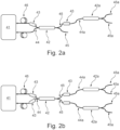
- the light source assembly shown in figure 2a comprises a light source arrangement 41, a first multimode coupler 42, a second line multimode coupler 42a and two mode scramblers 43.
- the first multimode coupler 42 comprises two input arms 44 and two output arms 45.
- the second line multimode coupler 42a comprises one input arm 44a and two output arms 45a.
- the light source arrangement may be any of the light source arrangement disclosed above configured for delivering two light beams, one for each of the two input arms 44 of the first multimode coupler 42.
- One of the light beams of the light source arrangement 41 may be delivered by free space and/or by fiber to a first arm of the first multimode coupler 42 via one of the scramblers 43.
- the other one of the light beams of the light source arrangement 41 may be delivered by free space and/or by fiber to a second arm of the first multimode coupler 42 without passing any scrambler, or alternatively, may also include a scrambler.
- One of the output arms 45 of the first multimode coupler 42 is in optical communication via an optical communication path - here illustrated by a fiber coupling - with the input arm 44a of the second line multimode coupler 42a and the second of the scramblers 43 is arranged in the optical communication path.
- the output light portion at the one of the output arms 45 of the first multimode coupler 42 not in optical connection with any second line coupler has an intensity, which is about twice the intensity of the each of the output beams of the respective output arms 45a of the second line multimode coupler 42a.
- the light source assembly shown in figure 2b is a variation of the light source assembly of figure 2a and differs therefrom in that it comprises further scramblers 33 and a further second line coupler 42a.
- a scrambler 43 is arranged at each of the light path from the light source arrangement 41 to the respective input arms 44 to the first multimode coupler 42 and further each of the output arms 45 of the first multimode coupler 42 is in optical communication via an optical communication path - here illustrated by a fiber coupling - with the input arm44a of the respective second line multimode couplers 42a and the scramblers 43 are arranged in each of the optical communication paths.
- the second line multimode couplers 42a are advantageously equal. Thereby the output light portions of each output arm 45a of each second line multimode coupler 44a have substantially equal intensity and may be divided further if desired.
- the light source assembly shown in figure 3 comprises a light source arrangement 51, a first multimode coupler 52, two second line multimode couplers 52a, four third line multimode couplers 52b and a plurality of mode scramblers, one arranged in each light path to an input arm of the respective couplers 52, 52a, 52b.
- the first multimode coupler 52 is a 2x2 coupler and each of the second line and third line couplers 52a, 52b are 1x2 couplers. It should be understood that each of the couplers 52, 52a, 52b in variations of the light source assembly may have a different number of input and/or output arms. Generally, it is desired that second and higher line couplers have one single input arm.
- the light source arrangement 51 may be any of the light source arrangement disclosed above configured for delivering 2 light beams, one for each of the input arms of the first multimode coupler 52.
- the light may be delivered from the light source 51 to the input arms of the first multimode coupler 52 by fiber and/or via free space.
- Each of the second line couplers is arranged for receiving light from an output arm of the first coupler 52 and for delivering light to two third line couplers.
- N outputs 55b may deliver output light portions of substantially equal intensity wherein N is 8.
- the light source assembly of figure 4 is a variation of the light source assembly of figure 3 and differs therefrom in that the light source assembly further comprises 8 fourth line multimode couplers 52c each with one input arm and two output arms and where each fourth line multimode coupler 52c is in optical communication via an optical communication path - here illustrated by a fiber coupling - to receive light from an output arm of a third line coupler 52b and wherein a scrambler 53 is arranged in each of the optical communication paths between the third line couplers 52b and the fourth line couplers.
- N outputs 55c may deliver output light portions of substantially equal intensity wherein N is 16.
- the light source assembly shown in figure 5 comprises a light source arrangement 61, a first multimode coupler 62, two second line multimode couplers 62a, six third line multimode couplers 62b, twelve fourth line multimode couplers 62c and a plurality of mode scramblers 63 one arranged in each light path to an input arm of the respective couplers 62, 62a, 62b, 62c.
- the first multimode coupler 62 is a 2x2 coupler the two second line coupler are 2x3 couplers and each of the third line and fourth line couplers 62b, 62c are 1x2 couplers.
- the light source arrangement 61 may be any of the light source arrangement disclosed above configured for delivering 2 light beams, one for each of the input arms of the first multimode coupler 62.
- the light may be delivered from the light source 61 to the input arms of the first multimode coupler 62 by fiber and/or via free space.
- Each of the second line couplers 62a is arranged for receiving light from an output arm of the first coupler 62 and for delivering light to the respective input arms of three of the third line couplers 62b.
- Each third line coupler 62b is arranged for receiving light from an output arm of a second line coupler 62a and for delivering light to the respective input arms of two of the fourth line couplers 62c.
- N outputs 65c may deliver output light portions of substantially equal intensity wherein N is 24.
- the light source assembly of the embodiment shown in figure 6 is a variation of the light source assembly of figure 3 and differs therefrom in that the light source arrangement 51a comprises a first and a second light source 59a, 59b and a first and a second filter 57a, 57b arranged for filtering the light of respectively the first and the second light source 59a, 59b.
- the first and the second light source 59a, 59b may be equal or different e.g. at least one of them may be a broadband light source.
- the first and the second filter 57a, 57b may be substantially the same or different and preferably include at least one tunable wavelength filter.
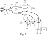
- Figure 7 shows a light source assembly comprising, a first multimode coupler 72, two second line multimode couplers 72a, four third line multimode couplers 72b and a plurality of mode scramblers 73, one mode scrambler 73 arranged in each light path to an input arm of the respective couplers 72, 72a, 72b.
- a light source arrangement (not shown) is arranged to supply light to each of the input arms of the first multimode coupler 72.
- the light source assembly has M inputs provided by the input arms of the first multimode coupler 72, so here M is 2.
- the light source assembly has N outputs provided by the output arms 75b of the third line multimode couplers 72b, so here N is 8.
- the light source assembly is arranged for illumination and sensing of pellets 76b in sensing chambers 76.
- Each of the N outputs delivers an output light portion of essentially equal intensity.
- the respective output light portion of the N outputs may be supplied at the spatially discreetly arranged sensing chambers 76 for projecting illuminating beams 76a towards the pellets 76b for sensing one or more characteristics of the pellets, such as color, content, structure and etc.
- a light sensor such as a camera 77 is arranged in each sensing chamber 76 to image light reflected from the pellets 76b and the image data from the respective light sensors 77 are transmitted via wires 78 to a data analyzer 79.
- the light system may e.g. be arranged for supplying illumination for hyperspectral sensing as described in the PhD thesis by Otto Abildgaard "Broadband optical characterization of material properties". DTU Compute PHD-2014; No. 334, DOI: 10.11581/DTU:00000009 .
- the pellets comprise pills and the detector system is arranged for detecting if the coating on the pills fulfills one or more quality parameters.
- the sensing chamber 76 may comprise a pill coater.
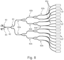
- Figure 8 shows a light source assembly comprising, a first multimode coupler 82, two second line multimode couplers 82a, four third line multimode couplers 82b, eight fourth line multimode couplers 82c and a plurality of mode scramblers 83, one mode scrambler 83 arranged in each light path to an input arm of the respective couplers 82, 82a, 82b, 82c.
- a not shown light source arrangement is arranged to supply light to each of the input arms of the first multimode coupler 82.
- the light source assembly has M inputs provided by the input arms of the first multimode coupler 82, so here M is 2.
- the light source assembly has N outputs provided by the output arms 85c of the fourth line multimode couplers 82c, so here N is 16.
- one or more, including all, of the output arms 5 ( figure 1a ), output arms 25 ( figures 1b-1d ), output arms 35 ( figure 1e ), output arms 45a ( figures 2a, 2b ), output arms 55b ( figures 3 , 6 ), output arms 55c ( figure 4 ), output arms 65c ( figure 5 ), output arm 75b ( figure 7 ) and output arms 87 ( figure 8 ) may be in optical communication with a mode scrambler, e.g., with a mode scrambler that receives light from the optical arm, such as by be positioned at the output of the optical arm.
- the light source assembly is arranged for illumination for supplying light at spatially discrete sites for illumination, e.g. for vehicle lights.
- Each of the N outputs delivers an output light portion of essentially equal intensity.
- the respective output light portion of the N outputs may be supplied at the spatially discreetly arranged lights 87 which may e.g. include left headlight, right head light, left rear light and etc.
- the left-hand side of Figure 9a shows the splitting ratio as a function of wavelength of a standard 1X2 splitter. Four runs of light were supplied to the splitter and the output light power of one of the output arms as well as the average (mean) was plotted. As seen, the variation between the runs and mean is quite substantial which is a clear indication of a high speckle pattern formation.
- the right-hand side of figure 9a shows the standard deviation as a function of wavelength and confirms that there is a high degree of speckle patter formation.
- the left-hand side of figure 9b shows the splitting ration as a function of wavelength of a first coupler of an embodiment of the light source assembly.
- Four runs of light were supplied to the splitter and the output light power of one of the output arms as well as the average (mean) was plotted. As seen, the variation between the runs and mean is very small, which is a clear indication of a very low speckle pattern formation.
- the right side of figure 9b shows the standard deviation as a function of wavelength and confirms that there is a very low degree of speckle pattern formation.
Landscapes
- Physics & Mathematics (AREA)
- General Physics & Mathematics (AREA)
- Optics & Photonics (AREA)
- Nonlinear Science (AREA)
- Engineering & Computer Science (AREA)
- General Engineering & Computer Science (AREA)
- Plasma & Fusion (AREA)
- Optical Couplings Of Light Guides (AREA)
- Optical Communication System (AREA)
Description
- The invention relates to a light source assembly for supplying light e.g. for illumination and/or sensing purpose(s).
- In many optical systems it is desired that beams of light may be supplied at several sites simultaneously and/or to deliver light with a desired spectral composition and/or profile.
- Use of broadband light sources, such as supercontinuum light sources for illumination and/or sensing purpose is e.g. described in
US 6,796,699 . The light from the broadband source may e.g. be filtered, such as wavelength filtered and/or polarization filtered prior to being applied for illumination and/or sensing. For some applications it may be advantageous to deliver two or more portions of the light of the broadband light, e.g. several light beams of different wavelength spectra or a beam with a spectrum comprising two or more wavelength peaks for the illumination and/or sensing. A beam with a spectrum comprising two or more wavelengths may include, for example, a first wavelength peak in the range 500-600 nm and a second peak in the range of 700-850 nm. -
WO16206700A1 -
US 2013/188251 A1 describes a system including a microscope and an inspection apparatus in which an objective lens having a large numerical aperture is used for detecting a defect existing inside a sample. The system has as a light source three super luminescent light emission diodes, SLEDs, at three wavelengths, the outputs of which are combined using two wavelength division multiplexing, WDM, couplers connected in series. The combined light is then power split into four using three 3dB couplers connected in a cascade. -
US 5077814 A describes an optical transmission line for use in an optical communication system. The transmission line includes a light source made of a semiconductor laser connected to a mode scrambler, which is in turn connected to an optical fiber coupler of a 1x4 division type. The mode scrambler has functions of a steady-state mode excitation of light, so that even in the case that there is used a light source such as a semiconductor laser having an intense directivity of the output light power, the desired characteristics of the optical fiber coupler can be obtained. -
US 4291940 A describes a low loss access coupler for multimode optical fiber distribution systems. -
WO 2014/130829 A1 describes systems for providing illumination to a measurement head for optical metrology. Illumination emanating from a broadband source is filtered utilizing a plurality of dichroic beam splitters. Each of the dichroic beam splitters is configured to direct illumination having a selected range of wavelengths along a respective delivery path. - The invention is defined by a light source assembly in accordance with the features of
claim 1. Preferred embodiments of the invention are described in the dependent claims. - The invention may provide a new solution for supplying light, in particular for illumination and/or sensing purposes, such as for calibrating and/or testing light systems.
- In an embodiment it is an object to provide a stable and robust light source assembly suitable for supplying light at several sites simultaneously and/or to deliver light with a desired spectral composition and/or profile.
- In an embodiment the light source assembly is based on a series of couplers, such as fused fiber couplers and at least one in between scrambler for providing a uniform distribution of at least two input beams, such input beams comprising different wavelengths.
- In an embodiment the light source assembly comprises a broadband source for delivering selected light portions light to one or more sites of use, where a filter is arranged for filtering off at least one wavelength range, which is scrambled in a scrambler and combined with at least one other light beam in a combiner. In an embodiment it has been found that by scrambling the input light beam prior to coupling in a fused fiber coupler a very efficient and stable coupling may be achieved while simultaneously the formation of speckle pattern on the output beam is very low or even absent.
- It has been found that the invention and/ or embodiments thereof have a number of additional advantages, which will be clear to the skilled person from the following description.
- Thus it has been found that an effective light distribution to a number of output light portions may be obtained and thanks to the invention light intensity variations between the output light portions may be very low or even absent and thus in an embodiment the output light portions may have essentially equal light intensity.
- The term "light" means at least one beam of light and may include two or more beams of light. The phrase "beam of light" and "light beam" are used interchangeably.
- The term "light portion" means a portion of the light, such as a portion of the light derived from the light source arrangement. The term "output light portion" is a portion of the light fed to the light source assembly from the light source arrangement and forming an output from the light source assembly.
- Unless otherwise specified or clear from the context, the term "substantially" means that ordinary measurement uncertainties, or product variances and tolerances, whichever are larger, are comprised.
- The phrase "essentially equal" should herein be taken to mean that variations within measurement tolerances are included.
- The term "light intensity," means herein a radiometric quantity, measured in watts per meter squared (W/m2) or mW/µm2. The terms power of light and light intensity are used interchangeably unless otherwise specified or clear from the context.
- It should be emphasized that the term "comprises/comprising" when used herein is to be interpreted as an open term, i.e. it should be taken to specify the presence of specifically stated feature(s), such as element(s), unit(s), integer(s), step(s) component(s) and combination(s) thereof, but does not preclude the presence or addition of one or more other stated features. Throughout the description or claims, the singular encompasses the plural unless otherwise specified or required by the context.
- The terms "core" and "core region" are used interchangeably and the terms "cladding" and "cladding region" are used interchangeably.
- The term "an embodiment" should be interpreted to include examples of the invention comprising the feature(s) of the mentioned embodiment.
- All features of the invention and embodiments of the invention as described herein, including ranges and preferred ranges, may be combined in various ways within the scope of the invention, unless there are specific reasons not to combine such features.
- A light source, which is not claimed, may comprise a number of couplers in optical communication and having inputs and outputs where a light source arrangement is arranged for supplying light to the inputs and output light portions are obtained via the outputs.
- The light source assembly has N outputs, where N is an integer. The light source assembly comprises:
- a light source arrangement arranged for supplying light to M inputs, where M is an integer and where M ≥ 2 and M ≤ N;
- a plurality of optical couplers each having at least one input arm and a plurality of output arms; and
- an integer number, P, of mode scramblers.
- It may be desired that M>2 and M< N.
- The plurality of optical couplers are arranged to divide the light supplied to the M inputs to the N outputs, where each of the N outputs includes light supplied to each of the M inputs.
- For at least one of the M inputs there is a respective mode scrambler of the P mode scramblers in the optical communication path between the light source and the at least one of the M inputs, and wherein at least one mode scrambler of the P mode scramblers is arranged in an optical communication path between an output arm of one optical coupler of the plurality of optical couplers and an input arm of a different optical coupler of the plurality of optical couplers.
- Thus the light source assembly provides an effective and relatively inexpensive system for evenly distributing light to N outputs. It has been found that, one or more, or even all, of the N outputs may have surprisingly low speckle pattern formation or even no detrimental formation of a speckle pattern. Such formation of speckle pattern is often a problem in prior art illumination systems.
- The phrase "no detrimental formation of a speckle pattern" is used to mean that the formation of a speckle pattern is at such low level that it in practice does not influence the use of the light source assembly.
- The light source assembly is configured such that for a plurality of the M inputs there is a respective mode scrambler of the P mode scramblers in the optical communication path between the light source arrangement and the respective M inputs. To enhance mode scrambling it may be advantageous that for at least two, such as for all of the M inputs, there is a respective mode scrambler of the P mode scramblers in the optical communication path between the light source assembly and the respective M inputs.
- For a cost effective arrangement it is desired that the M inputs are input arms of a first coupler of the optical couplers. In principle, the first coupler may have as many inputs as practically possible. Thus, the higher number of inputs, the longer the coupler requires to be for ensuring an effective coupling. M may be from 2 to10, such as from 2 to 4.
- An output arm of the first coupler is in optical communication via an optical communication path with an input arm of a second line coupler of the optical couplers, the optical communication path may be the optical communication path comprising the mode scrambler.
- The term "second line coupler" is herein used to denote a coupler arranged for receiving light derived from a first or first line coupler. If there is more than one first coupler, each of these is referred to as a first line coupler. In the same way the term "third line coupler" is a coupler receiving light derived from a second line coupler and so forth.
- The light source assembly comprises two or more first line couplers.
- Each of two or more output arms of the first coupler is in optical communication via an optical communication path with an input arm of a second line coupler of the optical couplers. Each of the optical communication paths may comprise a respective mode scrambler of the P mode scramblers. Thereby the light received from the first coupler is once more subjected to mode scrambling and thereby ensuring an even higher uniformity of the light intensity at the N outputs. The output arms of the first coupler are in optical communication with input arms of respective second line couplers. The second line couplers are substantially identical, i.e. they have substantially equal function.
- An output arm of at least one of the second line couplers is in optical communication via an optical communication path with an input arm of a third line coupler of the optical couplers. The optical communication path may be an optical communication path comprising a respective mode scrambler of the P mode scramblers. The output arms of the second coupler are in optical communication with input arms of respective third line couplers. The third line couplers are substantially identical i.e. they have substantially same function. Each output arm of each second line couplers may be in optical communication with a respective input arm of a respective third line coupler.
- Each of two or more output arms of the second line coupler(s) is in optical communication via an optical communication path with an input arm of a third line coupler of the optical couplers. Each of the optical communication paths may comprise a respective mode scrambler of the P mode scramblers.
- In the same or corresponding way, the light source assembly may comprise a number of further line couplers, such as at least one-third line coupler, such as at least one fourth line coupler, such as at least one fifth line coupler. Respective mode scramblers of the P mode scramblers may be in respective optical communication paths between a lower numbered line coupler and a higher numbered line coupler.
- In principle, the scramblers may be equal or different from each other. However, generally it is desired that scrambler(s) arranged at the input arm(s) to coupler of same line number are substantially identical, i.e. the scramblers have substantially equal function.
- The arms of the optical couplers are fiber arms. The optical couplers are preferably fused fiber coupler(s) and/or AxB multimode combiner(s), where A and B independently of each other may be any integer and represent input arms and output arms respectively.
- The fused fiber coupler(s) may e.g. be any standard fused couplers, such as the couplers marketed by OZoptics, Canada.
- Examples of the AxB multimode combiner are the multi-mode fiber combiners marketed by Lightcomm Technology of Shenzhen, China. Such multi-mode fiber combiners are generally designed for high power fiber laser application and generally for combining two or more pump lasers into one or more multi-mode output fiber. Such multi-mode fiber combiners may be applied to split the light instead of or after combining light.
- The couplers may be individually selected from couplers preferably with m input arms and n output arms. The integers m and n may in principle be as many as practically possible and preferably, m is 1, 2, 3, 4, 5, 6 or 7 and n is 2, 3, 4, 5, 6 or 7.
- In principle, the couplers may be equal or different from each other. However, generally it is desired that coupler of same line numbers are substantially identical i.e. they have substantially same function.
- The couplers comprise at least one 2x2 coupler, optionally all of the remaining couplers are 1xn couplers and n is 2, 3, 4, 5 or 6. The at least one 2X2 coupler may be the first coupler.
- For effectively dividing the light from the light source arrangement into a relatively high number of output light portions it is desired one or more of the couplers, such as all of the couplers is/are arranged for dividing the input light substantially uniformly with respect to light intensity between its/their output arms, e.g. with a difference of 10 % or less, such as of 5 % or less, such as of 2 % or less difference in light identity relative to the highest light intensity.
- Each of one or more of the couplers is/are multimode couplers comprising multimode arms.
- N may be at least 4, such as from 5 to 40, such as from 6 to 32, such as from 8 to 16, such as 2 times M.
- M ≤ P < N, P may be at least 2, such as at least 3. P may be up to the total number of input arms.
- The scramblers may be selected from a "Step-Graded-Step" mode scrambler and a "Step Index with Bends" mode scrambler. However, in principle any mode scrambler capable of scrambling the light may be applied.
- The Step-Graded-Step mode scrambler may for example be an assembly comprising a fusion-spliced concatenation of a step-index profile, a graded-index profile and another step-index profile fiber. Each segment may be from 1 cm to approximately 1 meter long or even longer.
- The Step Index with Bend mode scrambler may e.g. be a step-index multimode fiber having a series of small radius bends and/or a fiber that is compressed against surfaces with high roughness.
- The light source arrangement comprises at least one light source but it should be understood that the light source arrangement may comprise as many light sources as desired, e.g. an array of LEDs. The light source arrangement may comprise two or more laser light sources.
- The light source may be narrow banded (e.g. spanning up to about 50 nm) in an example not according to the claims, or broad banded (e.g., spanning above 50 nm). The light source arrangement may comprise a light source spanning over at least 100 nm, such as at least 500 nm. According to the claims, the light source comprises a supercontinuum light source. The light source may span over at least one octave.
- The bandwidth or span of a light source is determined to include wavelengths with a spectral intensity of at least 10 µW/nm.
- The light from the light source may be pulsed or it may be a continuous light beam.
- The light source arrangement may comprise one or more additional optical elements, such as one or more optical filters, one or more amplifiers and/or one or more beam shaping elements. These one or more optical elements may form part of one or more beam conditioner.
- The light source arrangement may comprise a light source selected from a fiber laser, an LED, a solid-state laser, a semiconductor laser or any combinations thereof. The light source arrangement may comprise two or more lasers.
- According to the invention as claimed, a light source assembly comprises a light source arrangement comprising a supercontinuum light source and a multimode coupler, wherein the multimode coupler is a multimode fused coupler comprising at least two input arms and at least two output arms, wherein the at least two input arms are configured for receiving two or more light beams from the light source arrangement, wherein the two or more light beams are derived from the supercontinuum light source and wherein a mode scrambler is arranged in each of the at least two input arms for mode scrambling two or more of said light beams before they enter the multimode coupler, wherein each of the two or more light beams derived from the supercontinuum light source and scrambled in the mode scrambler has a first beam M2 factor prior to being scrambled in the mode scrambler and wherein the mode scrambler is arranged for mode scrambling to increase the first beam M2 factor to a second beam M2 factor, larger than the first beam M2 factor.
- The light source assembly is thus configured for effectively distributing broadband light to obtain a number of output light portions. Thanks to the invention one or more, or all, of the output light portions, may have very low speckle or even no detrimental formation of speckle pattern.
- Thus, the light source assembly ensures a distribution of a light beam with a relatively low M2 factor into several output light portions with substantially equal light intensity.
- The M2 factor, also called beam quality factor or beam propagation factor, is a common measure of the beam quality of a laser beam. The beam M2 factor may be determined according to ISO Standard 11146. Thus, it has been found that by lowering the beam quality (increasing the beam M2 factor) of the light source of the light source arrangement, the light intensity the light may be even more evenly distribution at the outputs.
- The multimode couplers may be as the couplers described above.
- In an embodiment the multimode coupler or couplers is/are designed as a 50/50 coupler. At least one coupler is preferably a graded index coupler, or a step index coupler, preferably having cores of at least about 100 µm, such as at least about 200 µm.
- In an embodiment the light source assembly is configured to provide that at least one of the light beams is derived from the supercontinuum light source and delivered by free space coupling from the light source arrangement to the multimode coupler via the mode scrambler In an embodiment the light source assembly is configured to provide that at least one of the light beams is derived from the supercontinuum light source and is delivered from the light source arrangement at least partly by fiber coupling to the multimode via the mode scrambler
- The phrase "a light beam derived from a light source" means the entire beam of light from the light source, or any portion thereof, such as a wavelength filtered portion, a polarization filtered portion, and/or a portion derived by any other beam manipulating and/or splitting means. The light beam may e.g. portion of light may e.g. be obtained using a beam conditioner e.g. as described above for the first aspect.
- The mode scrambler may be any kind of mode scrambler e.g. as the mode scrambler described for the first aspect. In an embodiment the mode scrambler is a mode scrambling component, such as a non-fiber based mode scrambling component.
- In an embodiment the mode scrambler is a fiber mode scrambler. The fiber mode scrambler may be arranged at or forms part of a multimode fiber optically connected to an input arm of the mode scrambler.
- The light source arrangement may comprise any kind of beam conditioner. In an embodiment the light source arrangement comprises a wavelength filter for filtering light from the broadband light source to provide a filtered light beam of the one or more light beams derived from the broadband light source. The scrambler is advantageously configured for receiving and scrambling the filtered light beam prior to entering the coupler.
- In an embodiment the light source arrangement comprises an optical filter, such as an absorbing glass filter, an interference-based filter with a dielectric coating, a grating, a Fabry-Pérot interferometer, a prism based filter, a bandpass filter, a notch filter and/or any combinations thereof. The light source arrangement may comprise two or more optical filters.
- The filter may advantageously be a tunable filter.
- In an embodiment the light source arrangement comprises a wavelength filter, such as a band pass filter e.g. an AOTF (acousto-optic tunable filter), the wavelength filter preferably being wavelength tunable. In an embodiment the AOTF is configured for filtering off two or more wavelength ranges from a beam from the broadband source. The light source arrangement may comprise two or more wavelength filters.
- In an embodiment the light source arrangement comprises two wavelength filters arranged for filtering off two or more wavelength ranges from an input light beam from the broadband light source. The light source arrangement preferably comprises a beam splitter arranged for splitting the input light beam from the broadband light source in two beam portions, the wavelength filters being arranged for filtering the respective beam portions.
- In an embodiment the light source arrangement comprises a wavelength combiner, such as a Wavelength Division Multiplexer (WDM). In an embodiment optionally the wavelength combiner is configured for combining light from one or more wavelength filters and/or unfiltered light from one or more light sources.
- A wavelength combiner is also sometimes referred to as a spectral beam combiner or an incoherent beam combiner and is configured for combining beams comprising different wavelengths.
- In an embodiment the wavelength combiner is configured for combining two or more high-power laser beams so as to obtain a single beam not only with correspondingly higher power but also with more or less preserved beam quality and thus with increased brightness (power).
- In an embodiment the wavelength combiner is configured for combining two or more beams with different (e.g., non-overlapping) optical wavelength spectra, preferably ensuring that the wavelengths propagate in the same direction.
- In an embodiment the wavelength combiner is arranged to receive and combine light from two different light sources, such as from two or more diodes, such as from an array of diodes.
- In an embodiment the wavelength combiner is arranged to receive and combine light beams having different (e.g., non-overlapping) wavelength spectra, such as light beams from different light sources.
- In an embodiment the wavelength combiner is arranged to receive and combine beams from one or more wavelength filters, such as from one wavelength filter arranged to filter light from a supercontinuum light source. For example the wavelength combiner may be arranged to receive and combine beams with different (e.g. non overlapping) wavelength spectra, where the beams are beams from a filtered supercontinuum light source.
- For example the the light source arrangement may comprise the supercontinuum light source and a first filter filtering off a light beam having a first wavelength range and a second filter filtering off a second light beam having second wavelength range and the light source arrangement comprises a combiner arranged for combining the first and the second light beams.
- In an embodiment the light source arrangement is configured for filtering light from the supercontinuum light source to provide two or more filtered light beams of the one or more light beams derived from the supercontinuum light source and the mode scramblers are arranged for mode scrambling the respective filtered light beams before they enters the multimode coupler.
- The various combinations of light sources and/or filters, which may form part of the light source arrangement, ensure a high flexibility of the light source assembly. In particular the combination of the supercontinuum light source and one or more wavelength filters and an optional wavelength combiner is advantageous because the light source assembly may be configured for delivering light having a desired and selected wavelength spectrum, optionally for use for swiping (i.e., scanning) through the spectrum (e.g., for use in a sensing apparatus).
- In an embodiment the light source arrangement comprises at least one additional light source arranged for supplying a further light beam to the multimode coupler. The additional light source may be any kind of light source, such as a single mode light source or a multimode light source, a narrow band or a broadband light source. The light source assembly preferably comprises a mode scrambler configured for mode scrambling the further light beam prior to entering the fused coupler.
- Advantageously the broadband light source is a single mode light source or a few moded light source. In one embodiment, for example, the light source may have up to 20 guided modes per polarization direction, such as up to 10 guided modes per polarization direction determined at the peak wavelength of the first filtered light beam. Advantageously the broadband light source is a high power light source, e.g. light source having a peak power of 1 kW or more.
- The scrambler(s) is/are advantageously configured for increasing the number of excited modes in the one or more light beams derived from the broadband light source. Preferably, the derived and scrambled light beam(s) supplied to the coupler comprises more than 100 modes, such than more than 150 modes.
- The second beam M2 factor is larger than the first beam M2 factor, such as at least about 10 % larger, such as at least about 50 % larger, such as at least about 100 % larger or even at least 500 % larger.
- In an embodiment the one or more light beams derived from the broadband light source light beam has/have a bandwidth of up to about 50 nm, such as up to about 20 nm, such as up to about 10 nm, such as up to about 5 nm.
- In an embodiment the light beam from at least one of the output arms of the coupler is guided to a further coupler for being split into two or more sub-beams e.g. as described above comprising second line coupler(s) and optionally further line coupler(s).
- In an embodiment the light source assembly further comprises at least two further multimode couplers, each having a pair of input arms and a pair of output arms, one arm of the pair of input arms of each of two of such further multimode couplers is in optical communication with a respective output arm of the pair of output arms of the multimode coupler.
- The above and/or additional objects, features and advantages of the present invention will be further elucidated by the following illustrative and non-limiting description, with reference to the appended drawings.
- The figures are schematic and are not drawn to scale and may be simplified for clarity. Throughout, the same reference numerals are used for identical or corresponding parts.
-
Figure 1a is a schematic illustration of a light source assembly where the light source arrangement comprises one single light source. -
Figure 1b , which shows an embodiment that is not covered by the present invention, is a schematic illustration of a light source assembly where the light source arrangement comprises two light sources. -
Figure 1c , which shows an embodiment that is not covered by the present invention, is a schematic illustration of an embodiment of a light source assembly where the light source arrangement comprises a supercontinuum light source. -
Figure 1d , which shows an embodiment that is not covered by the present invention, is a schematic illustration of an embodiment of a light source assembly where the light source arrangement comprises a supercontinuum light source and a wavelength filter. -
Figure 1e is a schematic illustration of an embodiment of a light source assembly where the light source arrangement comprises a supercontinuum light source and two wavelength filters. -
Figure 2a , which shows an embodiment that is not covered by the present invention, is a schematic illustration of a light source assembly where the light source arrangement comprises a second line coupler. -
Figure 2b is a schematic illustration of a light source assembly where the light source arrangement comprises two second line couplers. -
Figure 3 is a schematic illustration of a light source assembly where the light source arrangement comprises second line and third line couplers. -
Figure 4 is a schematic illustration of a light source assembly where the light source arrangement comprises second line, third line and fourth line couplers. -
Figure 5 is a schematic illustration of a light source assembly where the second line couplers differ from the other couplers of the light source assembly. -
Figure 6 , which shows an embodiment that is not covered by the present invention, is a schematic illustration of an embodiment of a light source assembly, which is a variation of the light source assembly offigure 3 . -
Figure 7 is a schematic illustration of an embodiment of a light source assembly configured for supplying light at spatially discrete sites for illumination and/or sensing purpose. -
Figure 8 is a schematic illustration of an embodiment of a light source assembly configured for supplying light at a high number of spatially discrete sites for illumination and/or sensing purpose. -
Figure 9a show the splitting ratio of a standard 1X2 splitter and standard deviation thereof. -
Figure 9b show the splitting ratio of a first coupler of an embodiment of the light source assembly and standard deviation thereof. - The light source assembly shown in
figure 1a comprises a light source arrangement 1 amultimode coupler 2 and two mode scramblers 3. - The
multimode coupler 2 comprises two input arms 4 and two output arms 5. The mode scramblers 3 are arranged in the optical path between thelight source arrangement 1 and the optical arms 4, at the respective input arms 4. Thelight source arrangement 1 comprises a single light source (not shown) and at least one splitter (not shown) for splitting the light of the light source to deliver two light beams to the respective input arms 4 of themultimode coupler 2. As illustrated, the light beams delivered from thelight source arrangement 1 may be delivered fully or partly by fiber 6 to themultimode coupler 2 via the respective mode scramblers 3. Alternatively, one or both of the mode scramblers 3 may be located before, i.e. optically upstream of the fiber 6. - The light source assembly shown in
figure 1b comprises a light source arrangement, amultimode coupler 12 and amode scrambler 13. - The
multimode coupler 12 comprises twoinput arms 14 and two output arms 15. The mode scrambler is arranged at one of the input arms 4 whereas no mode scrambler is arranged at the other of theinput arms 14. - The light source arrangement comprises a
first section 11a with a first light source and asecond section 11b with a second light source. The first lightsource arrangement section 11a is configured for delivering a light beam to themultimode coupler 12 via the input arm comprising themode scrambler 13. - The second light
source arrangement section 11b is configured for delivering a light beam to themultimode coupler 12 via the input arm without a mode scrambler. The first light source may be a single mode or a few moded light source, which when scrambled may increase in M2 value, as well as increase in the number of modes. Advantageously the second light source is configured for delivering a multimode light beam. Preferably, with a higher number of modes, such as 8 or higher. When the light beams are coupled in themultimode coupler 2 the combined light may have a high number of modes for ensuring an even split of light to the output arms 15. As illustrated the light beams delivered from the light source arrangement may be delivered fully or partly byfiber 16 to themultimode coupler 12. In a variation thereof themode scramblers 13 may be located before, i.e. optically upstream of, thefiber 16. - The light source assembly shown in
figure 1c comprises alight source arrangement 21, amultimode coupler 22 and amode scrambler 23. - The
multimode coupler 22 comprises oneinput arm 24 and two output arms 5. The mode scrambler is arranged at theinput arm 24. Thelight source arrangement 21 comprises a supercontinuum light source and is arranged for delivering a light beam at least partly viafiber 26 to theinput arm 24 of themultimode coupler 22. It should be understood that the supercontinuum light source in a variation thereof may be any broadband source. - The light source assembly shown in
figure 1d differs from the light source assembly offigure 1c in that thelight source arrangement 21a further comprises awavelength filter 27, e.g. an AOTF. The AOTF is arranged to receive the light beam from the supercontinuum light source via fiber and/or via free space, for wavelength filtering the received light beam and for delivering the derived light beam to theinput arm 24 of themultimode coupler 22 via themode scrambler 23. The derived beam may be delivered by fiber or by free space. - The light source assembly shown in
figure 1e comprises a light source arrangement 31, amultimode coupler 32 and twomode scramblers 33. - The
multimode coupler 32 comprises twoinput arms 34 and twooutput arms 35. Themode scramblers 33 are arranged at therespective input arms 34. - The light source arrangement 31 comprises a supercontinuum light source, a
splitter 38 and twowavelength filters 37 e.g. AOTFs. Thesplitter 38 is arranged to split the light from the supercontinuum system in two portions, which may be equal or different. The light beam from the supercontinuum light source may be transmitted via free space to thesplitter 38. Each of the AOTFs is arranged to receive one respective portion of light from the splitter and to wavelength filter the received portion of light. The light portions from thesplitter 38 may be transmitted via free space to the respective AOTF. The wavelength filtered portions of light are supplied viafibers 36 to therespective arms 34 of themultimode coupler 32 via therespective mode scramblers 33. The AOTF may be configured to filter off corresponding wavelength of light or the AOTF may be configured to be independently tunable. Thereby for example, two different range of wavelengths may be combined in thecombiner 32 and split into output portions having substantially equal intensity in theoutput arms 35. - The
light source arrangements - The light source assembly shown in
figure 2a comprises alight source arrangement 41, a firstmultimode coupler 42, a second linemultimode coupler 42a and twomode scramblers 43. - The first
multimode coupler 42 comprises twoinput arms 44 and twooutput arms 45. The second linemultimode coupler 42a comprises oneinput arm 44a and twooutput arms 45a. - The light source arrangement may be any of the light source arrangement disclosed above configured for delivering two light beams, one for each of the two
input arms 44 of the firstmultimode coupler 42. One of the light beams of thelight source arrangement 41 may be delivered by free space and/or by fiber to a first arm of the firstmultimode coupler 42 via one of the scramblers 43.The other one of the light beams of thelight source arrangement 41 may be delivered by free space and/or by fiber to a second arm of the firstmultimode coupler 42 without passing any scrambler, or alternatively, may also include a scrambler. - One of the
output arms 45 of the firstmultimode coupler 42 is in optical communication via an optical communication path - here illustrated by a fiber coupling - with theinput arm 44a of the second linemultimode coupler 42a and the second of thescramblers 43 is arranged in the optical communication path. - The output light portion at the one of the
output arms 45 of the firstmultimode coupler 42 not in optical connection with any second line coupler has an intensity, which is about twice the intensity of the each of the output beams of therespective output arms 45a of the second linemultimode coupler 42a. - The light source assembly shown in
figure 2b is a variation of the light source assembly offigure 2a and differs therefrom in that it comprisesfurther scramblers 33 and a furthersecond line coupler 42a. Thus in the light source assembly offigure 2a ascrambler 43 is arranged at each of the light path from thelight source arrangement 41 to therespective input arms 44 to the firstmultimode coupler 42 and further each of theoutput arms 45 of the firstmultimode coupler 42 is in optical communication via an optical communication path - here illustrated by a fiber coupling - with the input arm44a of the respective second linemultimode couplers 42a and thescramblers 43 are arranged in each of the optical communication paths. The second linemultimode couplers 42a are advantageously equal. Thereby the output light portions of eachoutput arm 45a of each second linemultimode coupler 44a have substantially equal intensity and may be divided further if desired. - The light source assembly shown in
figure 3 comprises alight source arrangement 51, a firstmultimode coupler 52, two second linemultimode couplers 52a, four third linemultimode couplers 52b and a plurality of mode scramblers, one arranged in each light path to an input arm of therespective couplers multimode coupler 52 is a 2x2 coupler and each of the second line andthird line couplers couplers - The
light source arrangement 51 may be any of the light source arrangement disclosed above configured for delivering 2 light beams, one for each of the input arms of the firstmultimode coupler 52. The light may be delivered from thelight source 51 to the input arms of the firstmultimode coupler 52 by fiber and/or via free space. - Each of the second line couplers is arranged for receiving light from an output arm of the
first coupler 52 and for delivering light to two third line couplers. By the light source assembly offigure 3 N outputs 55b may deliver output light portions of substantially equal intensity wherein N is 8. - The light source assembly of
figure 4 is a variation of the light source assembly offigure 3 and differs therefrom in that the light source assembly further comprises 8 fourth linemultimode couplers 52c each with one input arm and two output arms and where each fourth linemultimode coupler 52c is in optical communication via an optical communication path - here illustrated by a fiber coupling - to receive light from an output arm of athird line coupler 52b and wherein ascrambler 53 is arranged in each of the optical communication paths between thethird line couplers 52b and the fourth line couplers. - By the light source assembly of
figure 4 N outputs 55c may deliver output light portions of substantially equal intensity wherein N is 16. - The light source assembly shown in
figure 5 comprises alight source arrangement 61, a firstmultimode coupler 62, two second linemultimode couplers 62a, six third linemultimode couplers 62b, twelve fourth linemultimode couplers 62c and a plurality ofmode scramblers 63 one arranged in each light path to an input arm of therespective couplers multimode coupler 62 is a 2x2 coupler the two second line coupler are 2x3 couplers and each of the third line andfourth line couplers - The
light source arrangement 61 may be any of the light source arrangement disclosed above configured for delivering 2 light beams, one for each of the input arms of the firstmultimode coupler 62. The light may be delivered from thelight source 61 to the input arms of the firstmultimode coupler 62 by fiber and/or via free space. - Each of the
second line couplers 62a is arranged for receiving light from an output arm of thefirst coupler 62 and for delivering light to the respective input arms of three of thethird line couplers 62b. Eachthird line coupler 62b is arranged for receiving light from an output arm of asecond line coupler 62a and for delivering light to the respective input arms of two of thefourth line couplers 62c. - By the light source assembly of
figure 5 N outputs 65c may deliver output light portions of substantially equal intensity wherein N is 24. - The light source assembly of the embodiment shown in
figure 6 is a variation of the light source assembly offigure 3 and differs therefrom in that thelight source arrangement 51a comprises a first and a secondlight source second filter light source light source second filter -
Figure 7 shows a light source assembly comprising, a firstmultimode coupler 72, two second linemultimode couplers 72a, four third linemultimode couplers 72b and a plurality ofmode scramblers 73, onemode scrambler 73 arranged in each light path to an input arm of therespective couplers multimode coupler 72. - The light source assembly has M inputs provided by the input arms of the first
multimode coupler 72, so here M is 2. The light source assembly has N outputs provided by theoutput arms 75b of the third linemultimode couplers 72b, so here N is 8. - The light source assembly is arranged for illumination and sensing of
pellets 76b in sensingchambers 76. Each of the N outputs delivers an output light portion of essentially equal intensity. The respective output light portion of the N outputs may be supplied at the spatially discreetly arrangedsensing chambers 76 for projecting illuminatingbeams 76a towards thepellets 76b for sensing one or more characteristics of the pellets, such as color, content, structure and etc. - A light sensor, such as a
camera 77 is arranged in eachsensing chamber 76 to image light reflected from thepellets 76b and the image data from the respectivelight sensors 77 are transmitted viawires 78 to adata analyzer 79. The light system may e.g. be arranged for supplying illumination for hyperspectral sensing as described in the PhD thesis by Otto Abildgaard "Broadband optical characterization of material properties". DTU Compute PHD-2014; No. 334, DOI: 10.11581/DTU:00000009. - In an embodiment the pellets comprise pills and the detector system is arranged for detecting if the coating on the pills fulfills one or more quality parameters. The
sensing chamber 76 may comprise a pill coater. -
Figure 8 shows a light source assembly comprising, a firstmultimode coupler 82, two second linemultimode couplers 82a, four third linemultimode couplers 82b, eight fourth line multimode couplers 82c and a plurality ofmode scramblers 83, onemode scrambler 83 arranged in each light path to an input arm of therespective couplers multimode coupler 82. - The light source assembly has M inputs provided by the input arms of the first
multimode coupler 82, so here M is 2. The light source assembly has N outputs provided by the output arms 85c of the fourth line multimode couplers 82c, so here N is 16. - With reference to the above discussed figures and embodiments, it is noted that one or more, including all, of the output arms 5 (
figure 1a ), output arms 25 (figures 1b-1d ), output arms 35 (figure 1e ),output arms 45a (figures 2a, 2b ),output arms 55b (figures 3 ,6 ),output arms 55c (figure 4 ),output arms 65c (figure 5 ),output arm 75b (figure 7 ) and output arms 87 (figure 8 ) may be in optical communication with a mode scrambler, e.g., with a mode scrambler that receives light from the optical arm, such as by be positioned at the output of the optical arm. - The light source assembly is arranged for illumination for supplying light at spatially discrete sites for illumination, e.g. for vehicle lights. Each of the N outputs delivers an output light portion of essentially equal intensity. The respective output light portion of the N outputs may be supplied at the spatially discreetly arranged
lights 87 which may e.g. include left headlight, right head light, left rear light and etc. - The left-hand side of
Figure 9a shows the splitting ratio as a function of wavelength of a standard 1X2 splitter. Four runs of light were supplied to the splitter and the output light power of one of the output arms as well as the average (mean) was plotted. As seen, the variation between the runs and mean is quite substantial which is a clear indication of a high speckle pattern formation. The right-hand side offigure 9a shows the standard deviation as a function of wavelength and confirms that there is a high degree of speckle patter formation. - The left-hand side of
figure 9b shows the splitting ration as a function of wavelength of a first coupler of an embodiment of the light source assembly. Four runs of light were supplied to the splitter and the output light power of one of the output arms as well as the average (mean) was plotted. As seen, the variation between the runs and mean is very small, which is a clear indication of a very low speckle pattern formation. The right side offigure 9b shows the standard deviation as a function of wavelength and confirms that there is a very low degree of speckle pattern formation.
Claims (10)
- A light source assembly comprising a light source arrangement (1, 31a, 41, 51, 61) comprising a supercontinuum light source and a multimode coupler (2, 22, 32, 42, 52, 72, 82), wherein the multimode coupler (2, 22, 32, 42, 52, 72, 82) is a multimode fused coupler comprising at least two input arms (4, 34, 44, 54) and at least two output arms (5, 35, 45, 55), wherein the at least two input arms (4, 34, 44, 54) are configured for receiving two or more light beams from the light source arrangement, wherein the two or more light beams are derived from the supercontinuum light source and wherein a mode scrambler (23, 33, 53, 73, 83) is arranged in each of the at least two input arms for mode scrambling two or more of said light beams before they enter the multimode coupler (2, 22, 32, 42, 52, 72, 82), wherein each of the two or more light beams derived from the supercontinuum light source and scrambled in the mode scrambler (23, 33, 53, 73, 83) has a first beam M2 factor prior to being scrambled in the mode scrambler (23, 33, 53, 73, 83) and wherein the mode scrambler (23, 33, 53, 73, 83) is arranged for mode scrambling to increase the first beam M2 factor to a second beam M2 factor, larger than the first beam M2 factor.
- The light source assembly of claim 1, wherein the mode scrambler (23, 33, 53, 73, 83) comprises a mode scrambling component, such as a non-fiber based mode scrambling component.
- The light source assembly of any one of the preceding claims, wherein said light source arrangement comprises a wavelength tunable filter (27, 37) for filtering light from the supercontinuum light source to provide a filtered light beam of the one or more light beams derived from the supercontinuum light source, said scrambler being configured for receiving and scrambling said filtered light beam prior to entering the multimode coupler, wherein said wavelength filter is configured for filtering off two or more wavelength ranges from an input light beam from the broadband light source, said wavelength filter preferably being an acousto-optic tunable filter.
- The light source assembly of claim 3, wherein said supercontinuum light source comprises a few moded light source with up to 20 guided modes per polarization direction, such as up to 10 guided modes per polarization direction determined at the peak wavelength of a first filtered light beam.
- The light source assembly of any one of the preceding claims, wherein said multimode coupler (22, 32, 52, 72, 82) comprises a 50/50 coupler, said coupler being a graded index coupler, or a step index coupler.
- The light source assembly of claim 5, wherein said multimode coupler (22, 32, 52, 72, 82) comprises a 50/50 coupler having cores of at least about 100 µm, such as at least about 200 µm.
- The light source assembly of any one of the preceding claims, wherein said scrambler(s) (23, 33, 53, 73, 83) is/are configured for increasing the number of excited modes in the one or more light beams derived from the supercontinuum light source, said derived and scrambled light beam(s) supplied to said coupler comprises more than 100 modes, such than more than 150 modes.
- The light source assembly of any one of the preceding claims, wherein the second beam M2 factor is at least 10% larger than the first beam M2 factor, such as at least about 50 % larger, such as at least about 100 % larger or even at least 500 % larger, and/or.
- The light source assembly of any one of the preceding claims, wherein said one or more light beams derived from the supercontinuum light source light beam has/have a bandwidth of up to about 50 nm, such as up to about 20 nm, such as up to about 10 nm, such as up to about 5 nm.
- The light source assembly of any of the preceding claims, wherein the light beam from at least one of the output arms of the multimode coupler (52, 72, 82) is guided to a further coupler (52a, 72a, 82a) for being split into two or more sub-beams.
Applications Claiming Priority (2)
| Application Number | Priority Date | Filing Date | Title |
|---|---|---|---|
| DKPA201770307 | 2017-05-04 | ||
| PCT/DK2018/050090 WO2018202269A1 (en) | 2017-05-04 | 2018-05-02 | A light source assembly |
Publications (3)
| Publication Number | Publication Date |
|---|---|
| EP3619561A1 EP3619561A1 (en) | 2020-03-11 |
| EP3619561A4 EP3619561A4 (en) | 2021-01-20 |
| EP3619561B1 true EP3619561B1 (en) | 2024-08-14 |
Family
ID=64015859
Family Applications (1)
| Application Number | Title | Priority Date | Filing Date |
|---|---|---|---|
| EP18793843.6A Active EP3619561B1 (en) | 2017-05-04 | 2018-05-02 | A light source assembly |
Country Status (4)
| Country | Link |
|---|---|
| US (2) | US10983281B2 (en) |
| EP (1) | EP3619561B1 (en) |
| CN (2) | CN114200585A (en) |
| WO (1) | WO2018202269A1 (en) |
Families Citing this family (4)
| Publication number | Priority date | Publication date | Assignee | Title |
|---|---|---|---|---|
| WO2018202269A1 (en) | 2017-05-04 | 2018-11-08 | Nkt Photonics A/S | A light source assembly |
| EP4154055A1 (en) * | 2020-06-15 | 2023-03-29 | Univerza V Ljubljani | A device and a method for speckle-free laser illumination |
| CN117053143A (en) * | 2023-03-27 | 2023-11-14 | 桂林电子科技大学 | A cascade-type lighting quartz fiber combiner and its preparation method |
| CN118523154A (en) * | 2024-07-25 | 2024-08-20 | 比亚迪股份有限公司 | Red light fiber laser, car lamp and vehicle |
Citations (1)
| Publication number | Priority date | Publication date | Assignee | Title |
|---|---|---|---|---|
| US6963062B2 (en) * | 2003-04-07 | 2005-11-08 | Eksigent Technologies, Llc | Method for multiplexed optical detection including a multimode optical fiber in which propagation modes are coupled |
Family Cites Families (14)
| Publication number | Priority date | Publication date | Assignee | Title |
|---|---|---|---|---|
| US4291940A (en) * | 1977-06-13 | 1981-09-29 | Canadian Patents & Development Ltd. | Low loss access coupler for multimode optical fiber distribution systems |
| JPH02120706A (en) * | 1988-10-31 | 1990-05-08 | Sumitomo Electric Ind Ltd | optical communication path |
| EP0899837A1 (en) | 1997-08-23 | 1999-03-03 | PIRELLI CAVI E SISTEMI S.p.A. | Unequal couplers for multimode pumping optical amplifiers |
| US6373568B1 (en) * | 1999-08-06 | 2002-04-16 | Cambridge Research & Instrumentation, Inc. | Spectral imaging system |
| EP1164406B1 (en) | 2000-06-17 | 2019-04-17 | Leica Microsystems CMS GmbH | Method and device for illuminating an object |
| US8822905B2 (en) * | 2011-09-16 | 2014-09-02 | Alcatel Lucent | Optical mode couplers for multi-mode optical fibers |
| US9046697B2 (en) * | 2012-01-02 | 2015-06-02 | Jgm Associates, Inc. | Low-speckle light sources and displays employing multimode optical fiber |
| JP5158552B1 (en) | 2012-01-19 | 2013-03-06 | レーザーテック株式会社 | Microscope and inspection device |
| US9512985B2 (en) * | 2013-02-22 | 2016-12-06 | Kla-Tencor Corporation | Systems for providing illumination in optical metrology |
| US20160241796A1 (en) | 2015-02-18 | 2016-08-18 | Peter S. Curreri | Systems and methods for illuminating and viewing objects |
| JP6835752B2 (en) * | 2015-06-25 | 2021-02-24 | エヌケイティー フォトニクス アクティーゼルスカブNkt Photonics A/S | Delivery fiber assembly and broadband source |
| CN205790916U (en) * | 2016-05-31 | 2016-12-07 | 中国工程物理研究院激光聚变研究中心 | Super continuous spectrums laser generator |
| CN105811229A (en) * | 2016-05-31 | 2016-07-27 | 中国工程物理研究院激光聚变研究中心 | Supercontinuum laser generating device |
| WO2018202269A1 (en) | 2017-05-04 | 2018-11-08 | Nkt Photonics A/S | A light source assembly |
-
2018
- 2018-05-02 WO PCT/DK2018/050090 patent/WO2018202269A1/en not_active Ceased
- 2018-05-02 CN CN202111507116.0A patent/CN114200585A/en active Pending
- 2018-05-02 US US16/609,775 patent/US10983281B2/en active Active
- 2018-05-02 CN CN201880041213.5A patent/CN110832371B/en active Active
- 2018-05-02 EP EP18793843.6A patent/EP3619561B1/en active Active
-
2021
- 2021-04-19 US US17/234,361 patent/US11454763B2/en active Active
Patent Citations (1)
| Publication number | Priority date | Publication date | Assignee | Title |
|---|---|---|---|---|
| US6963062B2 (en) * | 2003-04-07 | 2005-11-08 | Eksigent Technologies, Llc | Method for multiplexed optical detection including a multimode optical fiber in which propagation modes are coupled |
Non-Patent Citations (1)
| Title |
|---|
| FU Y ET AL: "Beam quality factor of mixed modes emerging from a multimode step-index fiber", OPTIK, WISSENSCHAFTLICHE VERLAG GMBH, DE, vol. 121, no. 5, 1 March 2010 (2010-03-01), pages 452 - 456, XP026926949, ISSN: 0030-4026, [retrieved on 20090121], DOI: 10.1016/J.IJLEO.2008.08.003 * |
Also Published As
| Publication number | Publication date |
|---|---|
| EP3619561A4 (en) | 2021-01-20 |
| CN114200585A (en) | 2022-03-18 |
| US20210311257A1 (en) | 2021-10-07 |
| US10983281B2 (en) | 2021-04-20 |
| US11454763B2 (en) | 2022-09-27 |
| CN110832371A (en) | 2020-02-21 |
| CN110832371B (en) | 2022-01-25 |
| EP3619561A1 (en) | 2020-03-11 |
| US20200064551A1 (en) | 2020-02-27 |
| WO2018202269A1 (en) | 2018-11-08 |
Similar Documents
| Publication | Publication Date | Title |
|---|---|---|
| US11454763B2 (en) | Light source assembly | |
| JP5745851B2 (en) | Modular imaging device, module for the device, and method of operating the imaging device | |
| JP2023058479A (en) | A system for providing illumination in optical metrology | |
| US20020131049A1 (en) | Broadband light source system and method thereof | |
| US20220350070A1 (en) | Light system for supplying light | |
| KR100207602B1 (en) | Optical filter for preventing loss of optical power and optical demultiplexer using same | |
| US8503084B2 (en) | Optical arrangement and method for controlling and influencing a light ray | |
| JP2954941B2 (en) | Large-capacity wavelength division multiplexer | |
| JPH10311905A (en) | Refractive index distributed lens optical device | |
| US8891917B2 (en) | Transverse mode filter for waveguides | |
| KR20150032820A (en) | Laser-Operated Light Source | |
| JP6535848B2 (en) | Chip-type bundle fiber multiplexer and chip-type multi-wavelength light source | |
| US11886002B2 (en) | Optical multiplexing circuit and light source | |
| CN113848652A (en) | Shunt light equalizing system, laser device and gene sequencing system | |
| JP7679605B2 (en) | Pulse spectrometer and multi-fiber irradiation unit | |
| JP2004271743A (en) | Optical device | |
| JP2013057931A (en) | Device for distributing illumination light and detection light in microscope and its method | |
| JPH02151742A (en) | Apparatus for measuring loss distribution of light path containing optical switch | |
| JP2011112686A (en) | Light source unit, light source device and microscope system | |
| CN116134362B (en) | Multimodal microscopy system | |
| US20250251640A1 (en) | Supercontinuum system with spectral detection | |
| JP5083618B2 (en) | Confocal scanner microscope | |
| JP2001201655A (en) | Optical splitter | |
| JP2001124658A (en) | Branch optical line test system and branch optical line test method |
Legal Events
| Date | Code | Title | Description |
|---|---|---|---|
| STAA | Information on the status of an ep patent application or granted ep patent |
Free format text: STATUS: THE INTERNATIONAL PUBLICATION HAS BEEN MADE |
|
| PUAI | Public reference made under article 153(3) epc to a published international application that has entered the european phase |
Free format text: ORIGINAL CODE: 0009012 |
|
| STAA | Information on the status of an ep patent application or granted ep patent |
Free format text: STATUS: REQUEST FOR EXAMINATION WAS MADE |
|
| 17P | Request for examination filed |
Effective date: 20191203 |
|
| AK | Designated contracting states |
Kind code of ref document: A1 Designated state(s): AL AT BE BG CH CY CZ DE DK EE ES FI FR GB GR HR HU IE IS IT LI LT LU LV MC MK MT NL NO PL PT RO RS SE SI SK SM TR |
|
| AX | Request for extension of the european patent |
Extension state: BA ME |
|
| DAV | Request for validation of the european patent (deleted) | ||
| DAX | Request for extension of the european patent (deleted) | ||
| A4 | Supplementary search report drawn up and despatched |
Effective date: 20201223 |
|
| RIC1 | Information provided on ipc code assigned before grant |
Ipc: G02B 6/14 20060101ALN20201217BHEP Ipc: F21V 8/00 20060101AFI20201217BHEP Ipc: G02B 6/28 20060101ALI20201217BHEP Ipc: F21S 43/241 20180101ALI20201217BHEP |
|
| RIN1 | Information on inventor provided before grant (corrected) |
Inventor name: FEUCHTER, THOMAS Inventor name: KUBAT, IRNIS Inventor name: ISKHAKOV, TIMUR |
|
| STAA | Information on the status of an ep patent application or granted ep patent |
Free format text: STATUS: EXAMINATION IS IN PROGRESS |
|
| 17Q | First examination report despatched |
Effective date: 20220630 |
|
| REG | Reference to a national code |
Ref country code: DE Ref legal event code: R079 Free format text: PREVIOUS MAIN CLASS: G02B0006280000 Ipc: F21V0008000000 Ref country code: DE Ref legal event code: R079 Ref document number: 602018073121 Country of ref document: DE Free format text: PREVIOUS MAIN CLASS: G02B0006280000 Ipc: F21V0008000000 |
|
| GRAP | Despatch of communication of intention to grant a patent |
Free format text: ORIGINAL CODE: EPIDOSNIGR1 |
|
| STAA | Information on the status of an ep patent application or granted ep patent |
Free format text: STATUS: GRANT OF PATENT IS INTENDED |
|
| RIC1 | Information provided on ipc code assigned before grant |
Ipc: G02B 6/14 20060101ALN20240325BHEP Ipc: G02B 6/28 20060101ALI20240325BHEP Ipc: F21S 43/241 20180101ALI20240325BHEP Ipc: F21V 8/00 20060101AFI20240325BHEP |
|
| INTG | Intention to grant announced |
Effective date: 20240416 |
|
| GRAS | Grant fee paid |
Free format text: ORIGINAL CODE: EPIDOSNIGR3 |
|
| GRAA | (expected) grant |
Free format text: ORIGINAL CODE: 0009210 |
|
| STAA | Information on the status of an ep patent application or granted ep patent |
Free format text: STATUS: THE PATENT HAS BEEN GRANTED |
|
| P01 | Opt-out of the competence of the unified patent court (upc) registered |
Free format text: CASE NUMBER: APP_39728/2024 Effective date: 20240703 |
|
| AK | Designated contracting states |
Kind code of ref document: B1 Designated state(s): AL AT BE BG CH CY CZ DE DK EE ES FI FR GB GR HR HU IE IS IT LI LT LU LV MC MK MT NL NO PL PT RO RS SE SI SK SM TR |
|
| REG | Reference to a national code |
Ref country code: GB Ref legal event code: FG4D |
|
| REG | Reference to a national code |
Ref country code: CH Ref legal event code: EP |
|
| REG | Reference to a national code |
Ref country code: DE Ref legal event code: R096 Ref document number: 602018073121 Country of ref document: DE |
|
| REG | Reference to a national code |
Ref country code: IE Ref legal event code: FG4D |
|
| REG | Reference to a national code |
Ref country code: NL Ref legal event code: FP |
|
| REG | Reference to a national code |
Ref country code: LT Ref legal event code: MG9D |
|
| PG25 | Lapsed in a contracting state [announced via postgrant information from national office to epo] |
Ref country code: NO Free format text: LAPSE BECAUSE OF FAILURE TO SUBMIT A TRANSLATION OF THE DESCRIPTION OR TO PAY THE FEE WITHIN THE PRESCRIBED TIME-LIMIT Effective date: 20241114 |
|
| REG | Reference to a national code |
Ref country code: AT Ref legal event code: MK05 Ref document number: 1713599 Country of ref document: AT Kind code of ref document: T Effective date: 20240814 |
|
| PG25 | Lapsed in a contracting state [announced via postgrant information from national office to epo] |
Ref country code: FI Free format text: LAPSE BECAUSE OF FAILURE TO SUBMIT A TRANSLATION OF THE DESCRIPTION OR TO PAY THE FEE WITHIN THE PRESCRIBED TIME-LIMIT Effective date: 20240814 Ref country code: GR Free format text: LAPSE BECAUSE OF FAILURE TO SUBMIT A TRANSLATION OF THE DESCRIPTION OR TO PAY THE FEE WITHIN THE PRESCRIBED TIME-LIMIT Effective date: 20241115 Ref country code: PT Free format text: LAPSE BECAUSE OF FAILURE TO SUBMIT A TRANSLATION OF THE DESCRIPTION OR TO PAY THE FEE WITHIN THE PRESCRIBED TIME-LIMIT Effective date: 20241216 Ref country code: PL Free format text: LAPSE BECAUSE OF FAILURE TO SUBMIT A TRANSLATION OF THE DESCRIPTION OR TO PAY THE FEE WITHIN THE PRESCRIBED TIME-LIMIT Effective date: 20240814 |
|
| PG25 | Lapsed in a contracting state [announced via postgrant information from national office to epo] |
Ref country code: BG Free format text: LAPSE BECAUSE OF FAILURE TO SUBMIT A TRANSLATION OF THE DESCRIPTION OR TO PAY THE FEE WITHIN THE PRESCRIBED TIME-LIMIT Effective date: 20240814 |
|
| PG25 | Lapsed in a contracting state [announced via postgrant information from national office to epo] |
Ref country code: LV Free format text: LAPSE BECAUSE OF FAILURE TO SUBMIT A TRANSLATION OF THE DESCRIPTION OR TO PAY THE FEE WITHIN THE PRESCRIBED TIME-LIMIT Effective date: 20240814 |
|
| PG25 | Lapsed in a contracting state [announced via postgrant information from national office to epo] |
Ref country code: IS Free format text: LAPSE BECAUSE OF FAILURE TO SUBMIT A TRANSLATION OF THE DESCRIPTION OR TO PAY THE FEE WITHIN THE PRESCRIBED TIME-LIMIT Effective date: 20241214 Ref country code: AT Free format text: LAPSE BECAUSE OF FAILURE TO SUBMIT A TRANSLATION OF THE DESCRIPTION OR TO PAY THE FEE WITHIN THE PRESCRIBED TIME-LIMIT Effective date: 20240814 |
|
| PG25 | Lapsed in a contracting state [announced via postgrant information from national office to epo] |
Ref country code: HR Free format text: LAPSE BECAUSE OF FAILURE TO SUBMIT A TRANSLATION OF THE DESCRIPTION OR TO PAY THE FEE WITHIN THE PRESCRIBED TIME-LIMIT Effective date: 20240814 |
|
| PG25 | Lapsed in a contracting state [announced via postgrant information from national office to epo] |
Ref country code: RS Free format text: LAPSE BECAUSE OF FAILURE TO SUBMIT A TRANSLATION OF THE DESCRIPTION OR TO PAY THE FEE WITHIN THE PRESCRIBED TIME-LIMIT Effective date: 20241114 Ref country code: ES Free format text: LAPSE BECAUSE OF FAILURE TO SUBMIT A TRANSLATION OF THE DESCRIPTION OR TO PAY THE FEE WITHIN THE PRESCRIBED TIME-LIMIT Effective date: 20240814 |
|
| PG25 | Lapsed in a contracting state [announced via postgrant information from national office to epo] |
Ref country code: RS Free format text: LAPSE BECAUSE OF FAILURE TO SUBMIT A TRANSLATION OF THE DESCRIPTION OR TO PAY THE FEE WITHIN THE PRESCRIBED TIME-LIMIT Effective date: 20241114 Ref country code: PT Free format text: LAPSE BECAUSE OF FAILURE TO SUBMIT A TRANSLATION OF THE DESCRIPTION OR TO PAY THE FEE WITHIN THE PRESCRIBED TIME-LIMIT Effective date: 20241216 Ref country code: PL Free format text: LAPSE BECAUSE OF FAILURE TO SUBMIT A TRANSLATION OF THE DESCRIPTION OR TO PAY THE FEE WITHIN THE PRESCRIBED TIME-LIMIT Effective date: 20240814 Ref country code: NO Free format text: LAPSE BECAUSE OF FAILURE TO SUBMIT A TRANSLATION OF THE DESCRIPTION OR TO PAY THE FEE WITHIN THE PRESCRIBED TIME-LIMIT Effective date: 20241114 Ref country code: LV Free format text: LAPSE BECAUSE OF FAILURE TO SUBMIT A TRANSLATION OF THE DESCRIPTION OR TO PAY THE FEE WITHIN THE PRESCRIBED TIME-LIMIT Effective date: 20240814 Ref country code: IS Free format text: LAPSE BECAUSE OF FAILURE TO SUBMIT A TRANSLATION OF THE DESCRIPTION OR TO PAY THE FEE WITHIN THE PRESCRIBED TIME-LIMIT Effective date: 20241214 Ref country code: HR Free format text: LAPSE BECAUSE OF FAILURE TO SUBMIT A TRANSLATION OF THE DESCRIPTION OR TO PAY THE FEE WITHIN THE PRESCRIBED TIME-LIMIT Effective date: 20240814 Ref country code: GR Free format text: LAPSE BECAUSE OF FAILURE TO SUBMIT A TRANSLATION OF THE DESCRIPTION OR TO PAY THE FEE WITHIN THE PRESCRIBED TIME-LIMIT Effective date: 20241115 Ref country code: FI Free format text: LAPSE BECAUSE OF FAILURE TO SUBMIT A TRANSLATION OF THE DESCRIPTION OR TO PAY THE FEE WITHIN THE PRESCRIBED TIME-LIMIT Effective date: 20240814 Ref country code: ES Free format text: LAPSE BECAUSE OF FAILURE TO SUBMIT A TRANSLATION OF THE DESCRIPTION OR TO PAY THE FEE WITHIN THE PRESCRIBED TIME-LIMIT Effective date: 20240814 Ref country code: BG Free format text: LAPSE BECAUSE OF FAILURE TO SUBMIT A TRANSLATION OF THE DESCRIPTION OR TO PAY THE FEE WITHIN THE PRESCRIBED TIME-LIMIT Effective date: 20240814 Ref country code: AT Free format text: LAPSE BECAUSE OF FAILURE TO SUBMIT A TRANSLATION OF THE DESCRIPTION OR TO PAY THE FEE WITHIN THE PRESCRIBED TIME-LIMIT Effective date: 20240814 |
|
| PG25 | Lapsed in a contracting state [announced via postgrant information from national office to epo] |
Ref country code: SM Free format text: LAPSE BECAUSE OF FAILURE TO SUBMIT A TRANSLATION OF THE DESCRIPTION OR TO PAY THE FEE WITHIN THE PRESCRIBED TIME-LIMIT Effective date: 20240814 Ref country code: RO Free format text: LAPSE BECAUSE OF FAILURE TO SUBMIT A TRANSLATION OF THE DESCRIPTION OR TO PAY THE FEE WITHIN THE PRESCRIBED TIME-LIMIT Effective date: 20240814 Ref country code: DK Free format text: LAPSE BECAUSE OF FAILURE TO SUBMIT A TRANSLATION OF THE DESCRIPTION OR TO PAY THE FEE WITHIN THE PRESCRIBED TIME-LIMIT Effective date: 20240814 |
|
| PG25 | Lapsed in a contracting state [announced via postgrant information from national office to epo] |
Ref country code: EE Free format text: LAPSE BECAUSE OF FAILURE TO SUBMIT A TRANSLATION OF THE DESCRIPTION OR TO PAY THE FEE WITHIN THE PRESCRIBED TIME-LIMIT Effective date: 20240814 |
|
| PG25 | Lapsed in a contracting state [announced via postgrant information from national office to epo] |
Ref country code: CZ Free format text: LAPSE BECAUSE OF FAILURE TO SUBMIT A TRANSLATION OF THE DESCRIPTION OR TO PAY THE FEE WITHIN THE PRESCRIBED TIME-LIMIT Effective date: 20240814 |
|
| PG25 | Lapsed in a contracting state [announced via postgrant information from national office to epo] |
Ref country code: IT Free format text: LAPSE BECAUSE OF FAILURE TO SUBMIT A TRANSLATION OF THE DESCRIPTION OR TO PAY THE FEE WITHIN THE PRESCRIBED TIME-LIMIT Effective date: 20240814 Ref country code: SK Free format text: LAPSE BECAUSE OF FAILURE TO SUBMIT A TRANSLATION OF THE DESCRIPTION OR TO PAY THE FEE WITHIN THE PRESCRIBED TIME-LIMIT Effective date: 20240814 |
|
| REG | Reference to a national code |
Ref country code: DE Ref legal event code: R097 Ref document number: 602018073121 Country of ref document: DE |
|
| PLBE | No opposition filed within time limit |
Free format text: ORIGINAL CODE: 0009261 |
|
| STAA | Information on the status of an ep patent application or granted ep patent |
Free format text: STATUS: NO OPPOSITION FILED WITHIN TIME LIMIT |
|
| 26N | No opposition filed |
Effective date: 20250515 |
|
| PG25 | Lapsed in a contracting state [announced via postgrant information from national office to epo] |
Ref country code: SE Free format text: LAPSE BECAUSE OF FAILURE TO SUBMIT A TRANSLATION OF THE DESCRIPTION OR TO PAY THE FEE WITHIN THE PRESCRIBED TIME-LIMIT Effective date: 20240814 |
|
| REG | Reference to a national code |
Ref country code: CH Ref legal event code: H13 Free format text: ST27 STATUS EVENT CODE: U-0-0-H10-H13 (AS PROVIDED BY THE NATIONAL OFFICE) Effective date: 20251223 |
|
| PG25 | Lapsed in a contracting state [announced via postgrant information from national office to epo] |
Ref country code: LU Free format text: LAPSE BECAUSE OF NON-PAYMENT OF DUE FEES Effective date: 20250502 |
|
| PG25 | Lapsed in a contracting state [announced via postgrant information from national office to epo] |
Ref country code: CH Free format text: LAPSE BECAUSE OF NON-PAYMENT OF DUE FEES Effective date: 20250531 |
|
| REG | Reference to a national code |
Ref country code: BE Ref legal event code: MM Effective date: 20250531 |
|
| PG25 | Lapsed in a contracting state [announced via postgrant information from national office to epo] |
Ref country code: MC Free format text: LAPSE BECAUSE OF FAILURE TO SUBMIT A TRANSLATION OF THE DESCRIPTION OR TO PAY THE FEE WITHIN THE PRESCRIBED TIME-LIMIT Effective date: 20240814 |
|
| PGFP | Annual fee paid to national office [announced via postgrant information from national office to epo] |
Ref country code: GB Payment date: 20260317 Year of fee payment: 9 |
|
| PG25 | Lapsed in a contracting state [announced via postgrant information from national office to epo] |
Ref country code: IE Free format text: LAPSE BECAUSE OF NON-PAYMENT OF DUE FEES Effective date: 20250502 |
|
| PG25 | Lapsed in a contracting state [announced via postgrant information from national office to epo] |
Ref country code: BE Free format text: LAPSE BECAUSE OF NON-PAYMENT OF DUE FEES Effective date: 20250531 |
|
| PGFP | Annual fee paid to national office [announced via postgrant information from national office to epo] |
Ref country code: NL Payment date: 20260318 Year of fee payment: 9 |
|
| PGFP | Annual fee paid to national office [announced via postgrant information from national office to epo] |
Ref country code: FR Payment date: 20260317 Year of fee payment: 9 |
|
| PG25 | Lapsed in a contracting state [announced via postgrant information from national office to epo] |
Ref country code: LT Free format text: LAPSE BECAUSE OF FAILURE TO SUBMIT A TRANSLATION OF THE DESCRIPTION OR TO PAY THE FEE WITHIN THE PRESCRIBED TIME-LIMIT Effective date: 20240814 |
|
| PGFP | Annual fee paid to national office [announced via postgrant information from national office to epo] |
Ref country code: DE Payment date: 20260414 Year of fee payment: 9 |
|
| PG25 | Lapsed in a contracting state [announced via postgrant information from national office to epo] |
Ref country code: CY Free format text: LAPSE BECAUSE OF FAILURE TO SUBMIT A TRANSLATION OF THE DESCRIPTION OR TO PAY THE FEE WITHIN THE PRESCRIBED TIME-LIMIT Effective date: 20240814 |